Embed Size (px)
Citation preview
kit contents
5356 PINE AVE • FRESNO, CA • 93727USA TOLL FREE: 877.4X4.TOYS • WORLDWIDE: 559.252.4950
WWW.TRAIL-GEAR.COM
rear disc brake kit
2 ct.
140250-1-Kit (1979-1995 toyota pickup/4runner)
140250-1-INS
InstalL Instructions
Brake rotors
2 ct.Brackets
8 ct.(6) M10x1.5x40 Bolts(2) M10x1.5x35 BoltsM10x1.5 Toplock Nuts
2 ct.Brake calipers
2 ct.Adapter Rings
2 ct.(1) Long brake line(1) Short brake line
InstalL Instructions (Cont'd.)
caution
1. Read all instructions completely and carefully before you begin. If anything is not clear, please call our Tech Support line at 1.877.4X4.TOYS or 559.549.6737 before proceeding.
2. Check to make sure the kit is complete and that no parts are missing (refer to the Kit Contents List on the first page of these instructions). If anything is missing, please contact Trail-Gear at 559.252.4950.
3. Park vehicle on a clean, dry, flat, level surface and block the tires so the vehicle can not roll in either direction.
4. This kit is for off-road use only. It is recommended that the installationsteps below be performed by a competent mechanic. Installation of this kitmay change the braking characteristics of your vehicle. Buyers and users ofthis product hereby expressly assume all risks associated with the installationand use of this kit.
recommended tools
10mm11mm12mm14mm17mm
HammerJackJack Stands3/8” Drive Ratchet1/2” Drive RatchetTorque WrenchPressBearing PullerSeal PullerBrake Fluid (DOT 3)
3/8” Allen Socket17mm19 or 21mm Lug Nut Socket
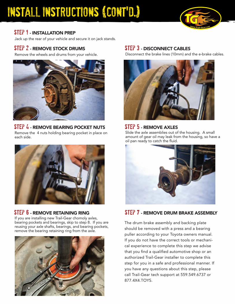
step 3 Disconnect the brake lines (10mm) and the e-brake cables.
InstalL Instructions (Cont'd.)
step 4 Remove the 4 nuts holding bearing pocket in place on each side.
step 5 Slide the axle assemblies out of the housing. A small amount of gear oil may leak from the housing, so have a oil pan ready to catch the fluid.
step 1 Jack up the rear of your vehicle and secure it on jack stands.
step 2 Remove the wheels and drums from your vehicle.
step 7
The drum brake assembly and backing plate should be removed with a press and a bearing puller according to your Toyota owners manual. If you do not have the correct tools or mechani-cal experience to complete this step we advise that you find a qualified automotive shop or an authorized Trail-Gear installer to complete this step for you in a safe and professional manner. If you have any questions about this step, please call Trail-Gear tech support at 559.549.6737 or 877.4X4.TOYS.
step 6 If you are installing new Trail-Gear chomoly axles, bearing pockets and bearings, skip to step 8. If you are reusing your axle shafts, bearings, and bearing pockets, remove the bearing retaining ring from the axle.
InstalL Instructions (Cont'd.)
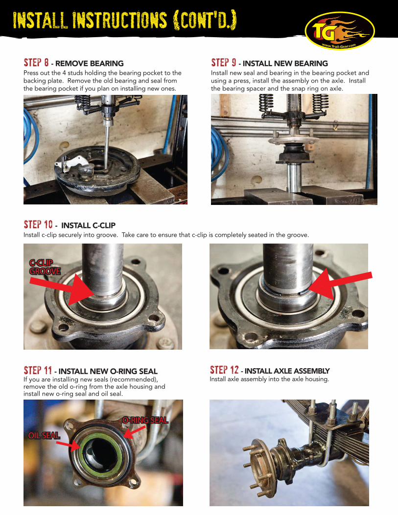
step 9 Install new seal and bearing in the bearing pocket and using a press, install the assembly on the axle. Install the bearing spacer and the snap ring on axle.
step 11 If you are installing new seals (recommended), remove the old o-ring from the axle housing and install new o-ring seal and oil seal.
Install axle assembly into the axle housing.step 12
step 8 Press out the 4 studs holding the bearing pocket to the backing plate. Remove the old bearing and seal from the bearing pocket if you plan on installing new ones.
step 10 Install c-clip securely into groove. Take care to ensure that c-clip is completely seated in the groove.
C-CLIPGROOVEC-CLIPGROOVE
OIL SEALOIL SEAL
O-RING SEALO-RING SEAL
InstalL Instructions (Cont'd.)
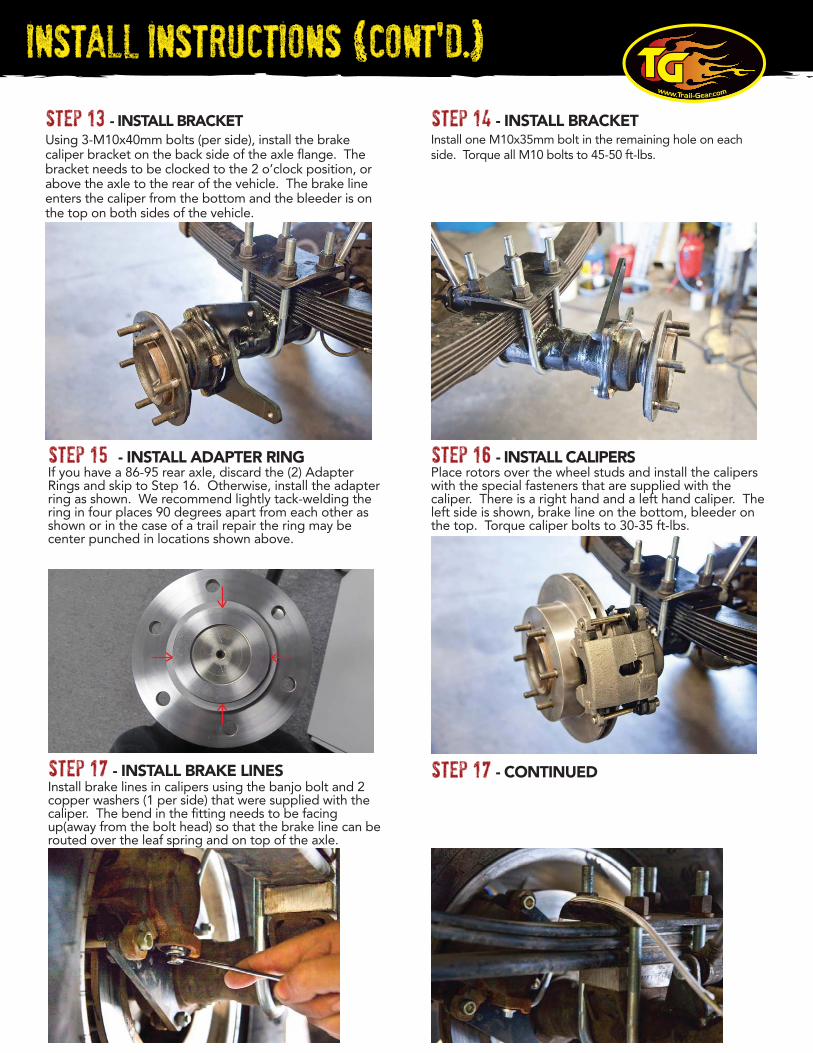
Using 3-M10x40mm bolts (per side), install the brake caliper bracket on the back side of the axle flange. The bracket needs to be clocked to the 2 o’clock position, or above the axle to the rear of the vehicle. The brake line enters the caliper from the bottom and the bleeder is on the top on both sides of the vehicle.
step 13
step 17
Place rotors over the wheel studs and install the calipers with the special fasteners that are supplied with the caliper. There is a right hand and a left hand caliper. The left side is shown, brake line on the bottom, bleeder on the top. Torque caliper bolts to 30-35 ft-lbs.
step 16 If you have a 86-95 rear axle, discard the (2) Adapter Rings and skip to Step 16. Otherwise, install the adapter ring as shown. We recommend lightly tack-welding the ring in four places 90 degrees apart from each other as shown or in the case of a trail repair the ring may be center punched in locations shown above.
step 15
Install one M10x35mm bolt in the remaining hole on each side. Torque all M10 bolts to 45-50 ft-lbs.
step 14
step 17 Install brake lines in calipers using the banjo bolt and 2 copper washers (1 per side) that were supplied with the caliper. The bend in the fitting needs to be facing up(away from the bolt head) so that the brake line can be routed over the leaf spring and on top of the axle.
InstalL Instructions (Cont'd.)
Install wheels and torque lug nuts.
step 19 - INSTALL WHEELS
step 20 - INSTALL VALVES AND LINE LOCK
ALL TRAIL-GEAR PRODUCTS ARE FOR OFFROAD USE ONLY
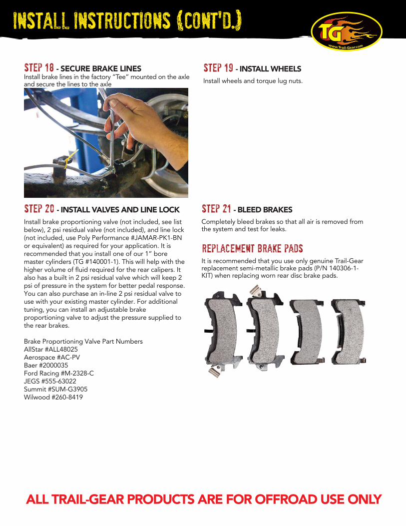
Install brake lines in the factory “Tee” mounted on the axle and secure the lines to the axle
step 18 - SECURE BRAKE LINES
Completely bleed brakes so that all air is removed from the system and test for leaks.
It is recommended that you use only genuine Trail-Gear replacement semi-metallic brake pads (P/N 140306-1-KIT) when replacing worn rear disc brake pads.
step 21 - BLEED BRAKES
replacement brake pads
Install brake proportioning valve (not included, see list below), 2 psi residual valve (not included), and line lock (not included, use Poly Performance #JAMAR-PK1-BN or equivalent) as required for your application. It is recommended that you install one of our 1” bore master cylinders (TG #140001-1). This will help with the higher volume of fluid required for the rear calipers. It also has a built in 2 psi residual valve which will keep 2 psi of pressure in the system for better pedal response. You can also purchase an in-line 2 psi residual valve to use with your existing master cylinder. For additional tuning, you can install an adjustable brake proportioning valve to adjust the pressure supplied to the rear brakes.
Brake Proportioning Valve Part NumbersAllStar #ALL48025Aerospace #AC-PVBaer #2000035Ford Racing #M-2328-CJEGS #555-63022Summit #SUM-G3905Wilwood #260-8419