Embed Size (px)
Citation preview
Optical Networks
Poompat Saengudomlert
Session 2
Building Blocks of Optical Networks:Optical Fibers & Optical Couplers
P. Saengudomlert (2018) Optical Networks Session 2 1 / 16
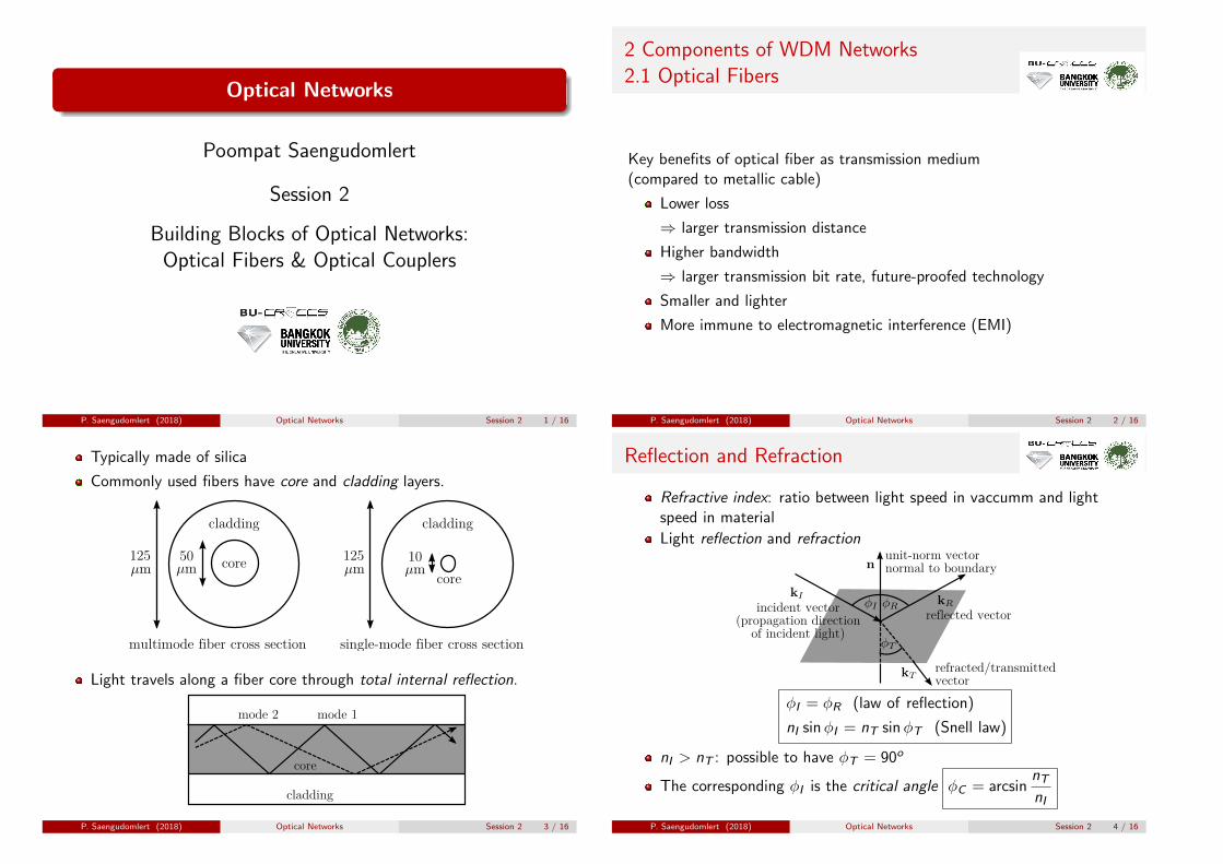
2 Components of WDM Networks2.1 Optical Fibers
Key benefits of optical fiber as transmission medium(compared to metallic cable)
Lower loss
⇒ larger transmission distance
Higher bandwidth
⇒ larger transmission bit rate, future-proofed technology
Smaller and lighter
More immune to electromagnetic interference (EMI)
P. Saengudomlert (2018) Optical Networks Session 2 2 / 16
Typically made of silica
Commonly used fibers have core and cladding layers.
cladding
core50125
cladding
core
10125
multimode fiber cross section single-mode fiber cross section
Light travels along a fiber core through total internal reflection.
cladding
core
mode 1mode 2
P. Saengudomlert (2018) Optical Networks Session 2 3 / 16
Reflection and Refraction
Refractive index: ratio between light speed in vaccumm and lightspeed in material
Light reflection and refraction
incident vector(propagation direction
of incident light)
reflected vector
unit-norm vectornormal to boundary
refracted/transmittedvector
ϕI = ϕR (law of reflection)
nI sinϕI = nT sinϕT (Snell law)
nI > nT : possible to have ϕT = 90o
The corresponding ϕI is the critical angle ϕC = arcsinnTnI
P. Saengudomlert (2018) Optical Networks Session 2 4 / 16

Numerical Aperture
Typically, ncore ≈ 1.5, ncladding/ncore ≈ 0.99 ⇒ ϕC ≈ 82o
cladding
core
air
At air-core interface, maximum θ yielding ϕ > ϕC is acceptance angle
nair sin θmax = ncore sin(90o−ϕC ) = ncore cosϕC =
√n2core − n2cladding� �� �
numerical aperture (NA)
The higher the NA, the easier it is to couple light into fiber.
P. Saengudomlert (2018) Optical Networks Session 2 5 / 16
Signal Degradation in Optical Fibers
Three types of signal degradation
Attenuation or loss⇒ low signal-to-noise ratio (SNR) at receiver
Dispersion⇒ pulse spreading and inter-symbol interference (ISI)
Fiber nonlinearity: scattering, Kerr effect, four wave mixing (FWM)⇒ reduced transmit power, pulse spreading, and crosstalk
Still cannot minimize all three at the same time!
P. Saengudomlert (2018) Optical Networks Session 2 6 / 16
Attenuation/Loss
Loss parameter αatt is usually expressed in dB/km.
P(L): signal power at distance L (in km) from transmitter
P(L)dBm = P(0)dBm − αattL
Three major low-loss windows
850 nm1300 nm1550 nm (most popular for WDM)
The 40-nm band (called C-band) around 1550 nm is widely used forlong distance transmission in WDM networks due to the availability ofoptical amplifiers.
P. Saengudomlert (2018) Optical Networks Session 2 7 / 16
Fiber Loss Characteristics
0.7 0.8 0.9 1.0 1.1 1.2 1.3 1.4 1.5 1.6 1.7 1.8 1.9 2.0
Wavelength
Opt
ical
loss
(dB
/km
)
8
7
6
5
4
3
2
1
0
Early 1980s
ModernFiber
Late1980s
Firs
t Win
dow
Sec
ond
Win
dow
Third
Win
dow
(L b
and)
Third
Win
dow
(C b
and)
Loss of single-mode fiber (www.cisco.com)
P. Saengudomlert (2018) Optical Networks Session 2 8 / 16

Dispersion
Large core diameter yields multiple propagation modes⇒ multimode fiber⇒ intermodal dispersion
cladding
core
mode 1mode 2
Dispersion: Different signal components travel at different speeds.
Intermodal dispersion⇒ pulse spreading⇒ inter-symbol interference (ISI)
P. Saengudomlert (2018) Optical Networks Session 2 9 / 16
ISI
es
Inputpulses
Distance along fiber →
Puls
e sh
apes
and
am
plitu
de
Outputpattern
ISI
pulses
ISI leads to high bit error rate (BER).
Most commercial transmission systems rely on sampling andthreshold-based detection. No complicated equalization is done atGbps rates.
P. Saengudomlert (2018) Optical Networks Session 2 10 / 16
Chromatic Dispersion
Small fiber core⇒ single propagation mode⇒ single-mode fiber⇒ no intermodal dispersion; chromatic dispersion dominant
Chromatic dispersion: Different frequency components travel atdifferent speeds.
Chromatic dispersion parameter D (typically in ps/nm/km)
D =1
L
dτ
dλ
L: fiber length (in km)τ : propagation delay (in ps)λ: wavelength of light (in nm)
P. Saengudomlert (2018) Optical Networks Session 2 11 / 16
Dispersion Characteristics
Waveguidedispersion
Materialdispersion
Totaldispersion
1.1 1.2 1.3 1.4 1.5 1.6 1.7
- 20
- 10
0
10
20
30
Dispersion,
(ps/(nm-km))
D
Wavelength
Normaldispersion
Anomalousdispersion
Material dispersion: ncore and ncladding are λ-dependent.Waveguide dispersion: Core/cladding power distribution (neff) isλ-dependent.
P. Saengudomlert (2018) Optical Networks Session 2 12 / 16

Fiber Refractive Index Profile
Can change chromatic dispersion through changing refractive index profile,i.e. changing waveguide dispersion.
(a) Step-index fiber (b) DSF (c) DCF
Dispersion-shifted fiber (DSF) has zero dispersion and low loss at1550 nm.
Dispersion compensation fiber (DCF) has dispersion of opposite signscompared to regular fiber to cancel dispersion.
P. Saengudomlert (2018) Optical Networks Session 2 13 / 16
Nonlinear Effects
At high transmit power (a few mW) and bit rate (> 2.5 Gbps),a transmitted signal is affected by fiber nonlinearity.
Scattering: power loss due to interaction with molecules
Kerr effects: neff is intensity dependent
Four-wave mixing (FWM): intermodulation product of fi , fj , fk ,yielding “fourth” frequencies at
±fi ± fj ± fk
P. Saengudomlert (2018) Optical Networks Session 2 14 / 16
Dispersion vs. Nonlinear Effects
Trade-off between dispersion and nonlinear effects.
For WDM, zero dispersion ⇒ high crosstalk from FWM
Distancefromcorecenter
Refractiveindex
Distancefromcorecenter
refr
activ
e index
distance from core center distance from core center
common NZ-DSF LEAF
Non-zero DSF (NZ-DSF) tolerates some dispersion to reduce FWM.
Large effective area fiber (LEAF) is a NZ-DSF that spreads opticalpower more evenly in fiber, reducing nonlinear effects.
P. Saengudomlert (2018) Optical Networks Session 2 15 / 16
2.2 Optical Couplers
A coupler is used to combine/split optical signals.
Simple to make by fusing 2 (or more) fibers together.
Relationship between input and output powers
[Pout,1
Pout,2
]= γ
[α 1− α
1− α α
] [Pin,1
Pin,2
]
α: coupling ratioγ: excess loss
Cannot do lossless combining.
Each input leads to outputs different in phase by π/2 rad.
P. Saengudomlert (2018) Optical Networks Session 2 16 / 16