Embed Size (px)
Citation preview

2-Colour DisplayHigh-Precision Digital Pressure Switch
The settings of the master sensor can be copied to the slave sensors.� Reduced setting efforts � Reduced chance of set-value input error
Settings can be Settings can be copiedcopied to up to to up to 1010 slave sensors at once. slave sensors at once.Settings can be copied to up to 10 slave sensors at once.
3-step setting-step setting3-step setting
PushPushPushEnd setting
3
PushPushPush
1 2
Adjust to set-value with buttons.
Added vacuum range.� Rated pressure range: 0.0 to –101.0 kPa
2 added outputs:� NPN or PNP open collector 2 outputs� NPN or PNP open collector 1 output + analogue output
(1 to 5 V or 4 to 20 mA)
–101 kPa
0
Master Unit 1Slave � Unit 2 Unit 10
CopyCopyCopy
Expanded pressure rangefor positive pressure typeto the vacuum range:� Rated pressure range: –0.1 to 1.0 MPa
1 MPa
0
–0.1 MPa(–100 kPa)
CAT.EUS100-70B-UKSeries ZSE30A(F)/ISE30A
RoHS compliant

Withstand pressure
Minimum unit setting
Rated pressure range
� Secret code setting functionThe key locking function keeps unauthorized users from tampering with buttons.
� Power-saving functionPower consumption is reduced by turning off the monitor (power consumption reduced by up to 20%.)
� Resolution-switch functionIt reduces the monitor to flicker.
� MPa/kPa switch functionVacuum, compound and/or positive pressure can be displayed both in MPa or kPa.
Bracket configuration allows mounting in four positions. The clip type allows easy removal of fittings.Fitting’s type and size can be changed.
Series
–0.100 to 1.000 MPa
1 MPa
0
–0.1 MPa(–100 kPa)
ISE30A (positive)
0.0 to –101.0 kPa
–101 kPa
0
ZSE30A (vacuum)
–100.0 to 100.0 kPa
–100 kPa
100 kPa
0
ZSE30AF (compound)
0.001 MPa0.1 kPa
500 kPa500 kPa
0.1 kPa
NPN or PNP open collector 1 outputNPN or PNP open collector 2 outputs
NPN or PNP open collector 1 output + Analogue output (voltage or current)Output
R1/8, NPT1/8 (M5 female threaded)ø4, ø6, ø5/32, ø1/4 one-touch fittings
Piping
Set pressure range –0.105 to 1.050 MPa–105.0 to 105.0 kPa10.0 to –105.0 kPa
Replaceable one-touch fittings
Connector cover added.
4-digit display allows easy reading of displayed values.Example: 0.5 MPa
Lead wire
4-digit display
Additional functions
One-touch fitting
Clip
Lead wire with connector
(2 m)
Connector cover
Mounting
Series
1.5 MPa
Possible to check set-value during key locking
Series 30A(New)
(Accuracy does not changed, only displayed values.)1/1000 1/100
Series 30(Conventional)
Bracket A Bracket B/C
Mountingexample
Bracket BMountingexample
Bracket CMountingexample
Panel mountMountable side by side without clearance
One opening!• Reduction of panel-cut job• Space-saving
Features 1

How to Order
For vacuum/compound pressure
ISE30AFor positivepressure 01 N M
ZSE30A 01 N M
Rated pressure rangeISE30A –0.1 to 1 MPa
OutputNPN open collector 1 outputPNP open collector 1 outputNPN open collector 2 outputsPNP open collector 2 outputsNPN open collector 1 output + Analogue voltage outputNPN open collector 1 output + Analogue current outputPNP open collector 1 output + Analogue voltage outputPNP open collector 1 output + Analogue current output
NPABC Note)
D Note)
E Note)
F Note)
Rated pressure rangeZSE30A
ZSE30AF0 to –101 kPa
–100 to 100 kPa
Option 1Without lead wire
Lead wire with connector(Lead wire length 2 m) Note)
L
Lead wire with connector(lead wire length 2 m) Note)
and with connector coverG
—
Note) For output types N and P, the number of core of lead wires will be 3, and for other types, it will be 4.
With unit display Note 2) switching function
Fixed SI unit Note 3)
With unit display Note 2) switching function(Initial value PSI)
—
P
M
Display unit
Note 2) Under the New Measure-ment Law, sales of switches with the unit switching function have not been allowed for use in Japan.
Note 3) Fixed unit kPa, MPa
Piping
R1/8 (M5 female threaded)
NPT1/8 (M5 female threaded)
One-touch fitting ø4 mm, ø5/32 inch
One-touch fitting ø6 mm
One-touch fitting ø1/4 inch
One-touch fitting ø4 mm, ø5/32 inch
One-touch fitting ø6 mm
One-touch fitting ø1/4 inch
01
N01
C4H
C6H
N7H
C4L
C6L
N7L
Straight type
Elbow type
Note) Made to Order
Note) Made to Order
Note 1) Made to Order
Note)
Note 1)
Option 3
Symbol Calibrationcertificate
—YKT
Operating manualBooklet
Made to Order (P.12)
X510 For M12 4-pinpre-wired connector
Available only for output “A” or “B”.
2-Color Display High-Precision Digital Pressure Switch
Series ZSE30A(F)/ISE30A
®
RoHS
Connector cover
Option 2None
Bracket A
A1
Bracket B
A2
Bracket C
A3
Panel mount adapter
B
Panel mount adapter + Front protection cover
D
—
1

Specifications
Piping Specifications
Model 01 N01 C4H C6H
Sensor pressure receiving area: Silicon
C3602 (electroless nickel plated)O-ring: HNBR
N7H C4L C6L N7L
—
ø1/4 inch
—
ø6 mm
—
ø4 mmø5/32 inch
ø1/4 inch
—
ø6 mm
—
——————
ø4 mmø5/32 inch
—
NPT1/8M5 x 0.8
—
R1/8M5 x 0.8
— —
—
One-touch fitting, Straight type
One-touch fitting, Elbow type
Sensor pressure receiving area
Piping port
Including lead wire with connector (3 cores, 2 m)Including lead wire with connector (4 cores, 2 m)Excluding lead wire with connector
PBT, POM, Stainless steel 304, C3604 (electroless nickel plated)O-ring: NBR
81 g85 g43 g
70 g74 g32 g
Port size
Wettedpartsmaterial
Weight71 g75 g33 g
73 g77 g35 g
75 g79 g37 g
73 g77 g35 g
75 g79 g37 g
Optional Part No.When optional parts are required separately, use the following part numbers to place an order.
ZS-38-A1ZS-38-A2ZS-38-A3ZS-27-CZS-27-DZS-27-01ZS-38-3LZS-38-4LZS-38-3G
Bracket ABracket BBracket CPanel mount adapterPanel mount adapter + front protection coverFront protection coverLead wire with connectorLead wire with connectorLead wire with connector (with connector cover)
Mounting screw (with 2 pcs. of M3 x 5L)
Mounting screw (with 2 pcs. of M3 x 5L)
Mounting screw (with 2 pcs. of M3 x 5L)
Mounting screw (with 2 pcs. of M3 x 8L)
Mounting screw (with 2 pcs. of M3 x 8L)
3 cores, for 1 output, 2 m4 cores, for 2 outputs, 2 m3 cores, for 1 output, 2 m
Part no. Option Note
ZS-38-4GZS-38-5LZS-38-UZS-38-C4HZS-38-C6HZS-38-N7HZS-38-C4LZS-38-C6LZS-38-N7L
Lead wire with connector (with connector cover)Lead wire with a connector for copyingLead wire unit with a connector for copyingOne-touch fittings ø4 mm straightOne-touch fittings ø6 mm straightOne-touch fittings ø1/4 inch straightOne-touch fittings ø4 mm elbowOne-touch fittings ø6 mm elbowOne-touch fittings ø1/4 inch elbow
4 cores, for 2 outputs, 2 m3 cores, copy function, 1 mCopy function (up to 10 slaves)O-ring, one-touch clip includedO-ring, one-touch clip includedO-ring, one-touch clip includedO-ring, one-touch clip includedO-ring, one-touch clip includedO-ring, one-touch clip included
Part no. Option Note
Note 1) If applied pressure fluctuates near the set value, set the hysteresis above the fluctuation range to prevent chattering.Note 2) When analogue the voltage output is selected, a simultaneous selection of switch output and current output is not available.Note 3) When analogue the current output is selected, a simultaneous selection of switch output and voltage output is not available.
Model ZSE30A (Vacuum pressure)Rated pressure rangeRegulating pressure rangeProof pressureSetting/display resolutionApplicable fluidPower supply voltageCurrent consumptionSwitch output
Repeatability
Analogue output
Hystere-sis
DisplayDisplay accuracyIndicator light
Environ-ment resistance
Temperature characteristics
Lead wire
Standards
0.0 to –101.0 kPa10.0 to –105.0 kPa
500 kPa0.1 kPa
0.6 to 5 V ±2.5% F.S.
ZSE30AF (Compound pressure)–100.0 to 100.0 kPa–105.0 to 105.0 kPa
500 kPa0.1 kPa
Air, non-corrosive gas, non-flammable gas12 to 24 VDC ±10%, Ripple (p-p) 10% or less (with power supply polarity protection)
40 mA or lessNPN or PNP open collector 1 output, NPN or PNP open collector 2 outputs (selectable)
80 mA28 V (with NPN output)
1 V or less (with load current of 80 mA)2.5 ms or less (with anti-chattering function: 20, 100, 500, 1000, 2000 ms)
Yes±0.2% F.S. ±1 digit
±1% F.S. or lessApprox. 1 k
±1% F.S. or less
4-digit, 7-segment, 2-colour LCD (Red and Green)±2% F.S. ±1 digit (ambient temperature of 25 ±30°C)
Lights up when switch output is ON. OUT1: Green, OUT2: RedIP40
Operating: 0 to 50°C, Stored: –10 to 60°C (no freezing or condensation)Operating/Stored: 35 to 85% RH (no condensation)
1000 VAC for 1 minute between live parts and enclosure50 MΩ or more between live parts and enclosure (at 500 VDC Megohmmeter)
10 to 150 Hz, 1.5 mm amplitude (or 20 m/s2 acceleration), in X, Y, Z directions, for 2 hours each (Non-energised)100 m/s2 in X, Y, Z directions, 3 times each (non-energised)
±2% F.S. (based on 25°C)
CE Marking, UL/CSA, RoHS compliance
Variable (0 or above) Note 1)
ISE30A (Positive pressure)–0.100 to 1.000 MPa–0.105 to 1.050 MPa
1.5 MPa0.001 MPa
Maximum load currentMaximum applied voltageResidual voltageResponse timeShort circuit protection
Voltageoutput
Hysteresis mode Window comparator mode
EnclosureOperating temperature rangeOperating humidity rangeWithstand voltageInsulation resistanceVibration resistanceImpact resistance
1 to 5V ±2.5% F.S.
2.4 to 20 mA ±2.5% F.S.4 to 20 mA ±2.5% F.S.
Output voltage
LinearityOutput impedance
Currentoutput
Output current
Linearity
Load impedance Maximum load impedance: 300 Ω with power supply voltage of 12 V; 600 Ω with power supply voltage of 24 V Minimum load impedance: 50 Ω
Oilproof heavy-duty vinyl cable, 3 cores ø3.5, 2 m 4 cores Conductor area: 0.15 mm2 (AWG26), Insulator O.D.: 1.0 mm
Note 2)
Note 3)
Series ZSE30A(F)/ISE30A
2

Descriptions
Analogue Output
Output voltage Output current
10.6
Pressure
5
BA C
Ana
logu
e ou
tput
[V]
42.4
Pressure
20
BA C
Ana
logu
e ou
tput
[mA
]
Functions (Refer to pages 10 and 11 for details.)
Copy function
Auto-preset function
Precision indicator setting function
Peak display function
Bottom display function
Key lock function (Security code input can be selected)
Zero-out function
Anti-chattering function
Unit display switching function
Power-saving mode
kPa⟺MPa switch function
Display resolution-switch function
Copies the settings of the master sensor to the slave sensors.
Calculates and enters rough set values automatically from the actual operating conditions.
Evens out deviations in the displayed value.
Can retain the maximum pressure value displayed during measurement.
Can retain the minimum pressure value displayed during measurement.
The key board can be locked to prevent any incorrect function of the switch.
The pressure display can be set at zero when the pressure is open to the atmosphere.
Prevents possible malfunction due to sudden fluctuations in the primary pressure by adjusting the response time.
Can convert the display value.
Reduces power consumption.
Converts display resolution from the normal value of 1/1000 to 1/100.It reduces the monitor to flicker.
Converts the unit between kPa and MPa.
Displays unit being used (only kPa and MPa).
Unit display
Lights up when switch output (OUT1) is turned ON.
OUT1 Output display (Green)
Use this button to select the mode or increase the ON/OFF set value.It is also used for switching to the peak display mode.
UP button
Use this button to switch the mode and set the set value.
S SET buttonUse this button to select the mode or decrease the ON/OFF set value.It is also used for switching to the bottom value display mode.
DOWN button
Lights up when switch output (OUT2) is turned ON.
OUT2 Output display (Red)
Displays the current pressure condition, setting mode, and error codes. A display colour type can be selected from either a single colour display with red or green, or 2-colour display in which green and red are switched accordeing to the output. Four different display settings are available.
LCD display
Range
For vacuumpressure
For compound pressure
For positivepressure
Rated pressure range
0.0 to –101.0 kPa
A
—
B
0
C
–101 kPa
–100.0 to 100.0 kPa — –100 kPa 100 kPa
–0.100 to 1.000 MPa –0.1 MPa 0 1 MPa
Series ZSE30A(F)/ISE30A2-Colour DisplayHigh-Precision Digital Pressure Switch
3

+
–
Brown DC (+)
Black OUT
Blue DC (–)
FUNC
Load
+
–
Load
Brown DC (+)
Black OUT
Blue DC (–)
FUNC
12 to24 VDC
Brown DC (+)
Black OUT1
White OUT2
FUNC
Blue DC (–)
Load
Load+
–
12 to24 VDC
Brown DC (+)
Black OUT1
White OUT2
FUNC
Blue DC (–)
Load
Load
+
–
12 to24 VDC
12 to24 VDC
Mai
n ci
rcui
tM
ain
circ
uit
Mai
n ci
rcui
tM
ain
circ
uit
Internal Circuits and Wiring Examples
Max. 80 mAResidual voltage 1 V or less
Max. 28 V, 80 mAResidual voltage 1 V or less
Max. 80 mAResidual voltage 1 V or less
Max. 28 V, 80 mAResidual voltage 1 V or less
Z/ISE30A(F)
Output
NPN (1 output)
N
NPN (2 outputs)
APNP (2 outputs)
B
PNP (1 output)
P
Note) The FUNC terminal is connected using a dedicated lead wire (ZS-38-5L or ZS-38-U) when the copy function is used. (Refer to “Copy function” on page 10.)
Series ZSE30A(F)/ISE30A
4

Load
Load
Brown DC (+)
Black OUT1
Blue DC (–)
FUNC
White OUT2+
–
12 to24 VDC
Load
Load
Brown DC (+)
Black OUT1
Blue DC (–)
FUNC
White OUT2+
–
12 to24 VDC
Load
Load
Brown DC (+)
Black OUT1
Blue DC (–)
FUNC
+
–
12 to24 VDC
White OUT2
Load
Load
Brown DC (+)
Black OUT1
Blue DC (–)
FUNC
+
–
12 to24 VDC
White OUT2
Mai
n ci
rcui
t
Mai
n ci
rcui
t
Mai
n ci
rcui
t
Mai
n ci
rcui
t
Max. 28 V, 80 mAResidual voltage 1 V or less
Analogue current outputMax. load impedance:
Power supply voltage 12 V: 300 Ω Power supply voltage 24 V: 600 Ω
Min. load impedance: 50 Ω
Max. 80 mAResidual voltage 1 V or less
Analogue current outputMax. load impedance:
Power supply voltage 12 V: 300 Ω Power supply voltage 24 V: 600 Ω
Min. load impedance: 50 Ω
Max. 28 V, 80 mAResidual voltage 1 V or less
Analogue voltage outputOutput impedance: Approx. 1 kΩ
Max. 80 mAResidual voltage 1 V or less
Analogue voltage outputOutput impedance: Approx. 1 kΩ
NPN (1 output) + Analogue voltage output
CPNP (1 output) + Analogue voltage output
E
NPN (1 output) + Analogue current output
DPNP (1 output) + Analogue current output
F
Note) The FUNC terminal is connected using a dedicated lead wire (ZS-38-5L or ZS-38-U) when the copy function is used. (Refer to “Copy function” on page 10.)
Series ZSE30A(F)/ISE30A2-Colour DisplayHigh-Precision Digital Pressure Switch
5
Dimensions
One-touch fitting ø4 mmø5/32 inch elbow
C4LOne-touch fitting ø6 mmelbow
C6LOne-touch fitting ø1/4 inchelbow
N7L
30
30
10
1.5
25 8 9.5
Lead wire with connector
01: R1/8N01: NPT1/8
20±0.1 2 x M3 x 0.5thread depth 4
M5 x 0.8
Widthacrossflats 12
20±
0.1
17.55
ø9.
8
ø14
10.85
20.7
15.6
ø9.3
10.85
ø14
17.95
ø10
10.85
22.85
16.1
ø11.6
10.85
21.75
ø10
.3
ø14
10.85
23.45
16.1
ø12
10.85
Z/ISE30A(F)
Piping
01 N01/
One-touch fitting ø4 mmø5/32 inch straight
C4HOne-touch fitting ø6 mmstraight
C6HOne-touch fitting ø1/4 inchstraight
N7H
Series ZSE30A(F)/ISE30A
6

Note) Bracket configuration allows mounting in four directions.
Note) Bracket configuration allows mounting in four directions.
With bracket
30
20
20
45
2
30
19
5.2
5.2
9.6 14
.7
30
34.6
25
42.5
20
30
20
45
5.5
7.5
20
7.2
5.2
9.1
13.65.2
16.4
30
1.6 25
Z/ISE30A(F)
Option 2
Bracket A(Option unit part no.: ZS-38-A1)
A1
42.5
(A)
Bracket C(Option unit part no.: ZS-38-A3)
A3
Bracket B(Option unit part no.: ZS-38-A2)
A2
Bracket B
Bracket C
A
41.4
53
B
16.4
28
Series ZSE30A(F)/ISE30A2-Colour DisplayHigh-Precision Digital Pressure Switch
7

Dimensions
34.5
34.5
8.5
Panel thickness 0.5 to 6
7.2 17.8 8 9.5
R4.5
47.8
R4.5
21
33.5
33.5
42.4 11 17.8 8 9.5
Panel thickness 0.5 to 6
Panel mount
Z/ISE30A(F)
Option 2
Panel mount adapter(Option unit part no.: ZS-27-C)
B
Panel mount adapter + Front protection cover(Option unit part no.: ZS-27-D)
D
Series ZSE30A(F)/ISE30A
8

1 pc. mounting Multiple (2 pcs. or more) horizontal mounting
Panel fitting dimensions
4 x R2 or less
310
–0.4
310 –0
.4
24 o
r m
ore
31 x n pcs. + 3.5 x (n pcs. – 1)
4 x R2 or less
310 –0
.4
24 or more
31 x
n p
cs. +
3.5
x (
n pc
s. –
1)
4 x R2 or less
310
–0.4
Series ZSE30A(F)/ISE30A
Multiple (2 pcs. or more) vertical mounting
2-Colour DisplayHigh-Precision Digital Pressure Switch
9

Master Slave(Max. 10 units)
Unit 1 Unit 2 Unit 10
DC
(+)
OU
T1
OU
T2
FU
NC
DC
(–)
DC
(+)
OU
T1
OU
T2
FU
NC
DC
(–)
DC
(+)
OU
T1
OU
T2
FU
NC
DC
(–)
DC
(+)
OU
T1
OU
T2
FU
NC
DC
(–)
Brow
n
Grey (Line for copying)
Blue
Brow
n
Grey (Line for copying)
Blue
Brow
n
Grey (Line for copying)
Blue
Brow
n
Grey (Line for copying)
Blue
Power
Slave-side sensor
Unit 1 Unit 2Unit n
(Max. 10 units)
ZS-38-5L (n + 1 pc.)orZS-38-U
Master-sidesensor
Function Details
Note) When the precision indicator setting function is used, set pressure value may change ±1 digit.
C Precision indicator setting function (F6)
0 Applied pressure+
Displayed value at the time of shipment
Adjustable range of display calibration function
±5% R.D.
Dis
play
pre
ssur
e va
lue
D Peak and bottom display function
E Key lock functionThis function prevents incorrect operations such as accidentally changing the set-value.
F Zero-out function
This function clears and resets the zero value on the display of measured pressure.For the pressure switch with analogue output, the analogue output shifts according to the indication.A displayed value can be adjusted within ±7% F.S. of the pressure when ex-factory (±3.5% F.S. for ZSE30AF (compound pressure)).
B Auto-preset function (F5)Auto-preset function, when selected in the setting, calculates and stores the set-value from the measured pressure.The optimum set-value is determined automatically by repeating vacuum and break with the target workpiece several times.
Fine adjustment of the indicated value of the pressure sensor can be made within the range of ±5% of the read value.The scattering of the indicated value can be eliminated.
Suction Verification
Work 1 Work 2
Work 1 Work 2 Work n
Work n
High
Vacuum
Max. A
P-1
n-1
Min. B
Atmosphere
Suction
Released
H-1
P_1 (P_2) = A – (A-B)/4n_1 (n_2) = B + (A-B)/4
P_1 or P_2 H_1 or H_2
H_1 (H_2) = (A-B)/2
Formula for Obtaining the Set-Value
A Copy function (F97)
The settings of the master sensor can be copied to several slave sensors, whichreduces the time taken for setting and prevents the input of wrong values.Settings can be copied to up to 10 slave sensors at once.(Max. transmission distance: 4 m)
This function constantly detects and updates the maximum minimum value and allows to hold the maximum/minimum pressure value.When the buttons are simultaneously pressed for 1 second or longer, while “holding”, the held value will be reset.
Steps to follow:1) The sensors are connected by a dedicated lead wire
(ZS-38-5L for master and one slave or ZS-38-U for master and up to 10 slaves). Copying is performed through a dedicated communication line.
2) Make the slave sensor which needs to be the master into the master by button operation. (Initially all sensors are set as slaves.)
3) Press the button on the master sensor to start copying.
Series ZSE30A(F)/ISE30A
10

H Anti-chattering function (F3)A large bore cylinder or ejector consumes a large volume of air in operation and may experience a temporary drop in the supply pressure. This function prevents detection of such temporary drops in the supply pressure as an error.
PrincipleThis function averages pressure values measured during the response time set by the user and then compares the average pressure value with the pressure set point value to output the result on the switch.
If the switch does not recover to normal even after all of the above-mentioned solutions have been applied, consult SMC for investigation.
Pressure �Momentary change
t (ms) t (ms) Time �
Time �
Time �
Averaging Averaging
Switch outputoperation innormalconditions
ON
OFF
Switch outputoperation whenanti-chatteringfunction is on.
ON
OFF
Pressure rangeP-1
H-1
Available response time settings
20 ms, 100 ms, 500 ms, 1000 ms, 2000 ms
I Unit display switching function (F0)Display units can be switched with this function.
Note) For the ZSE30A (vacuum pressure) and ZSE30AF (compound pressure), when the display unit is MPa, setting and display resolutions are changed.
Display unit
Min. unit setting
0.1
kPa
0.001
MPaNote)
PA
0.001
kgf/cm2
GF
0.001
bar
bAr
0.01
psi
PSi
0.1
inHg
inH
1
0.1 0.001 0.001 0.001 0.01 0.1 1
1 0.001 0.01 0.01 0.1
mmHg
mmH
ZSE30A(Vacuum pressure)
ZSE30AF(Compound pressure)
ISE30A(Positive pressure)
G Error indication function
ConditionError code(LCD display)Error description
Overcurrent error
Residualpressure error
Appliedpressure error
System error
Solution
Load current of switch output (OUT1) exceeds 80 mA. Shut off the power supply. After eliminating the output factor that caused the excess current, turn the power supply back on.
Reduce/increase supply pressure to within the regulating pressure range.
Bring the pressure back to atmospheric pressure and try using the zero-out function.
Load current of switch output (OUT2) exceeds 80 mA.
Supply pressure exceeds the maximum regulating pressure.
Supply pressure is below the minimum regulating pressure.
Internal data error
A pressure of ±7% F.S. of atmospheric pressure is applied in the zero-out function. (±3.5% F.S. or more for ZSE30AF (compound pressure))The switch will automatically return to measuring mode in 1 second, however. Due to individual product differences, the setting range of the zero-out function varies within 1% F.S.
Shut off the power supply and turn the power supply back on. If the power does not come back on, please contact SMC for an inspection.
J Power-saving mode (F7)It shifts to the power-saving mode without button operation for 30 seconds. It is set to the normal mode (power-saving mode is OFF) when ex-factory (decimal points and operation indicator light, only when the switch output is turned ON, blink in the power-saving mode.
K Secret code setting (F8)It can be set whether code number input is required or not when key is locked. It is set to input no code number when ex-factory.
F� in brackets stand for the function codes. Refer to the operating manual for how to operate and function codes in detail.
Series ZSE30A(F)/ISE30A2-Colour DisplayHigh-Precision Digital Pressure Switch
11

100 9.4
ø15
42.5+30
0
M12 4 pin connector
15.2 42.5
ø1514
29.6
100+30
0
15.2
Series ZSE30A(F)/ISE30AMade to OrderPlease contact SMC for detailed dimensions, specifications, and lead times.
M12 4-pin pre-wired connector (Lead wire length 100 mm)1
How to Order
ZSE30A(F) / ISE30A X510
Output specifications A: NPN open collector 2 outputs B: PNP open collector 2 outputs
Option cable ZS-38-4GM12
12
3 4
Connector pin numbers
Pin no. Pin description1234
DC (+)OUT (2)DC (–)
OUT (1)
1 Brown
4 Black
2 White
3 Blue
X510
12

13
Panel mountadapter
Panel mountadapter
Panel
Claw
Mounting screwM3 x 5L
Bracket B
Lever
Lead wire (Brown)
Lead wire (Blue)
Mounting screwM3 x 5L
Bracket A
Tube
One-touch fitting
1. Do not drop, bump, or apply excessive impacts (100 m/s2) while handling. Although the body of the sensor may not be damaged, the internal parts of the sensor could be damaged and lead to a malfunc-tion.
2. The tensile strength of the cord is 35 N. Applying a greater pulling force on it can cause a malfunc-tion. When handling, hold the body of the sensor—do not dangle it from the cord.
3. Do not exceed the screw-in torque of 7 to 9 N·m when connecting the pipe to the switch. Exceeding these values may cause the switch to malfunction.
4. Do not use pressure sensors with corrosive and/or flammable gases or liquids.
5. Allow a sufficient margin of tube length in piping in order to prevent application of torsional, tensile or moment load to the tubes and fittings.
6. When a brand of tubing other than SMC is used, make sure that the tolerance of the tube's O.D. satisfies the following specifications. 1) Nylon tubing: ±0.1 mm or less 2) Soft nylon tubing: ±0.1 mm or less 3) Polyurethane tubing: +0.15 mm or less, –0.2 mm or less
7. The applicable fluid is air. Consult SMC if the switch is to be used with other types of fluids.
WarningHandling
1. Incorrect wiring can damage the switch and cause a malfunction or erroneous switch output. Connec-tions should be done while the power is turned off.
2. Do not attempt to insert or pull the pressure sensor or its connector when the power is on. A switch output malfunction may occur.
Connection
Warning
1. Wire separately from power lines and high voltage lines, avoiding wiring in the same conduit with these lines. Malfunctions may occur due to noise from these other lines.
2. If a commercial switching regulator is used, make sure that the F.G. terminal is grounded.
Caution
1. This pressure switch is CE marked; however, it is not equipped with surge protection against lightning. Lightning surge countermeasures should be applied directly to system components as necessary.
2. This pressure switch does not have an explosion proof rating. Never use in the presence of an explo-sive gas as this may cause a serious explosion.
3. Do not use in an environment where static electricity can cause problems, otherwise system failure or malfunction may result.
Operating Environment
Warning
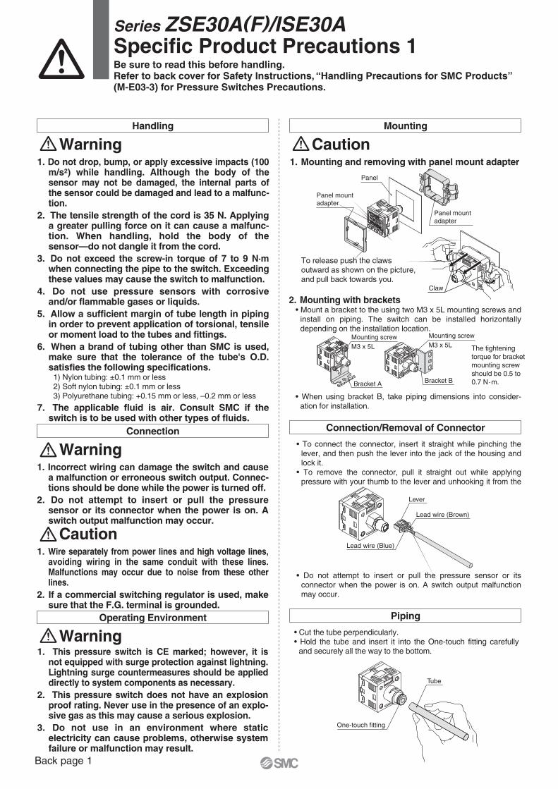
1. Mounting and removing with panel mount adapter
2. Mounting with brackets• Mount a bracket to the using two M3 x 5L mounting screws and
install on piping. The switch can be installed horizontally depending on the installation location.
To release push the claws outward as shown on the picture, and pull back towards you.
CautionMounting
• To connect the connector, insert it straight while pinching the lever, and then push the lever into the jack of the housing and lock it.
• To remove the connector, pull it straight out while applying pressure with your thumb to the lever and unhooking it from the
• When using bracket B, take piping dimensions into consider-ation for installation.
• Do not attempt to insert or pull the pressure sensor or its connector when the power is on. A switch output malfunction may occur.
Connection/Removal of Connector
• Cut the tube perpendicularly.• Hold the tube and insert it into the One-touch fitting carefully
and securely all the way to the bottom.
Piping
The tightening torque for bracket mounting screw should be 0.5 to 0.7 N·m.
Series ZSE30A(F)/ISE30ASpecific Product Precautions 1Be sure to read this before handling.Refer to back cover for Safety Instructions, “Handling Precautions for SMC Products” (M-E03-3) for Pressure Switches Precautions.
Back page 1

Set the pressure within the rated pressure range.The set pressure range is the range of pressure that is possible in setting.The rated pressure range is the range of pressure that satisfies the specifications (accuracy, linearity, etc.) on the switch.Although it is possible to set a value outside the rated pressure range, the specifications will not be guaranteed even if the value stays within the set pressure range.
CautionSet Pressure Range and Rated Pressure Range
Rated pressure range of switchSet pressure range of switch
Switch–100 kPa 0 100 kPa 500 kPa 1 MPa
Pressure range
ZSE30AF
ISE30A
–100 kPa
–105 kPa
100 kPa
105 kPa
For com-poundpressure
For positivepressure
For vacuumpressure
ZSE30A–101 kPa
–105 kPa
0
10 kPa
1 MPa–105 kPa
(–0.105 MPa)1.05 MPa
–100 kPa
Series ZSE30A(F)/ISE30ASpecific Product Precautions 2Be sure to read this before handling.Refer to back cover for Safety Instructions, “Handling Precautions for SMC Products” (M-E03-3) for Pressure Switches Precautions.
Back page 2

Lithuania +370 5 2308118 www.smclt.lt [email protected] +31 (0)205318888 www.smcpneumatics.nl [email protected] +47 67129020 www.smc-norge.no [email protected] +48 (0)222119616 www.smc.pl [email protected] +351 226166570 www.smc.eu [email protected] +40 213205111 www.smcromania.ro [email protected] +7 8127185445 www.smc-pneumatik.ru [email protected] +421 (0)413213212 www.smc.sk [email protected] +386 (0)73885412 www.smc.si [email protected] +34 902184100 www.smc.eu [email protected] +46 (0)86031200 www.smc.nu [email protected] +41 (0)523963131 www.smc.ch [email protected] +90 212 489 0 440 www.smcpnomatik.com.tr [email protected] UK +44 (0)845 121 5122 www.smcpneumatics.co.uk [email protected]
Specifications are subject to change without prior notice and any obligation on the part of the manufacturer.SMC CORPORATION Akihabara UDX 15F, 4-14-1, Sotokanda, Chiyoda-ku, Tokyo 101-0021, JAPAN Phone: 03-5207-8249 FAX: 03-5298-5362
1st printing RW printing RW 00 Printed in Spain
Austria +43 (0)2262622800 www.smc.at [email protected] +32 (0)33551464 www.smcpneumatics.be [email protected] +359 (0)2807670 www.smc.bg [email protected] Croatia +385 (0)13707288 www.smc.hr [email protected] Republic +420 541424611 www.smc.cz [email protected] Denmark +45 70252900 www.smcdk.com [email protected] Estonia +372 6510370 www.smcpneumatics.ee [email protected] +358 207513513 www.smc.fi [email protected] +33 (0)164761000 www.smc-france.fr [email protected] +49 (0)61034020 www.smc.de [email protected] +30 210 2717265 www.smchellas.gr [email protected] +36 23511390 www.smc.hu [email protected] +353 (0)14039000 www.smcpneumatics.ie [email protected] +39 0292711 www.smcitalia.it [email protected] +371 67817700 www.smclv.lv [email protected]
Safety Instructions Be sure to read “Handling Precautions for SMC Products” (M-E03-3) before using.
SMC Corporation (Europe)
1. The compatibility of the product is the responsibility of the person who designs the equipment or decides its specifications.Since the product specified here is used under various operating conditions, its compatibility with specific equipment must be decided by the person who designs the equipment or decides its specifications based on necessary analysis and test results. The expected performance and safety assurance of the equipment will be the responsibility of the person who has determined its compatibility with the product. This person should also continuously review all specifications of the product referring to its latest catalogue information, with a view to giving due consideration to any possibility of equipment failure when configuring the equipment.
2. Only personnel with appropriate training should operate machinery and equipment.The product specified here may become unsafe if handled incorrectly. The assembly, operation and maintenance of machines or equipment including our products must be performed by an operator who is appropriately trained and experienced.
3. . Do not service or attempt to remove product and machinery/equipment until safety is confirmed.1. The inspection and maintenance of machinery/equipment should only be
performed after measures to prevent falling or runaway of the driven objects have been confirmed.
2. When the product is to be removed, confirm that the safety measures as mentioned above are implemented and the power from any appropriate source is cut, and read and understand the specific product precautions of all relevant products carefully.
3. Before machinery/equipment is restarted, take measures to prevent unexpected operation and malfunction.
4. Contact SMC beforehand and take special consideration of safety measures if the product is to be used in any of the following conditions. 1. Conditions and environments outside of the given specifications, or use
outdoors or in a place exposed to direct sunlight.2. Installation on equipment in conjunction with atomic energy, railways, air
navigation, space, shipping, vehicles, military, medical treatment, combustion and recreation, or equipment in contact with food and beverages, emergency stop circuits, clutch and brake circuits in press applications, safety equipment or other applications unsuitable for the standard specifications described in the product catalogue.
3. An application which could have negative effects on people, property, or animals requiring special safety analysis.
4. Use in an interlock circuit, which requires the provision of double interlock for possible failure by using a mechanical protective function, and periodical checks to confirm proper operation.
Warning
Limited warranty and Disclaimer/Compliance Requirements The product used is subject to the following “Limited warranty and Disclaimer” and “Compliance Requirements”.Read and accept them before using the product.
1. The product is provided for use in manufacturing industries.The product herein described is basically provided for peaceful use in manufacturing industries. If considering using the product in other industries, consult SMC beforehand and exchange specifications or a contract if necessary. If anything is unclear, contact your nearest sales branch.
Caution
Limited warranty and Disclaimer1. The warranty period of the product is 1 year in service or 1.5 years after
the product is delivered, wichever is first.∗2)
Also, the product may have specified durability, running distance or replacement parts. Please consult your nearest sales branch.
2. For any failure or damage reported within the warranty period which is clearly our responsibility, a replacement product or necessary parts will be provided. This limited warranty applies only to our product independently, and not to any other damage incurred due to the failure of the product.
3. Prior to using SMC products, please read and understand the warranty terms and disclaimers noted in the specified catalogue for the particular products.
∗2) Vacuum pads are excluded from this 1 year warranty.A vacuum pad is a consumable part, so it is warranted for a year after it is delivered. Also, even within the warranty period, the wear of a product due to the use of the vacuum pad or failure due to the deterioration of rubber material are not covered by the limited warranty.
Compliance Requirements1. The use of SMC products with production equipment for the manufacture of
weapons of mass destruction (WMD) or any other weapon is strictly prohibited.
2. The exports of SMC products or technology from one country to another are governed by the relevant security laws and regulations of the countries involved in the transaction. Prior to the shipment of a SMC product to another country, assure that all local rules governing that export are known and followed.
These safety instructions are intended to prevent hazardous situations and/or equipment damage. These instructions indicate the level of potential hazard with the labels of “Caution,” “Warning” or “Danger.” They are all important notes for safety and must be followed in addition to International Standards (ISO/IEC)∗1), and other safety regulations.
∗1) ISO 4414: Pneumatic fluid power – General rules relating to systems. ISO 4413: Hydraulic fluid power – General rules relating to systems. IEC 60204-1: Safety of machinery – Electrical equipment of machines. (Part 1: General requirements) ISO 10218-1: Manipulating industrial robots - Safety. etc.
Caution indicates a hazard with a low level of risk which, if not avoided, could result in minor or moderate injury.
Warning indicates a hazard with a medium level of risk which, if not avoided, could result in death or serious injury.
Caution:
Warning:
Danger :Danger indicates a hazard with a high level of risk which, if not avoided, will result in death or serious injury.
Safety Instructions