Embed Size (px)
Citation preview
ANTENNAPRO D U CTS
w w w .a n ten n a pro d u cts .co m | 800.553.1507
GS-420
ENVIRONM ENTAL SPECS
-50C to +70C5% to 100%0 to 100,000 feet100 MPH operational0.5 inches radial iceMil-Std-810G, Method 514.6, Category 4, Procedure I, 90 minutes each axisMil-Std-810G, Method 514.6, Annex A, 4-600 Hz sweep, 2 hour dwell on all three axis,Mil-Std-810G, Method 514.6, Annex A, 4-600 Hz sweep, 2 hour dwell on all three axis,total of six hours.
TEMPERATURE RATING, OPERATIONALREALTIVE HUMIDITY, OPERATIONALALTITUDE, OPERATIONALWIND LOADING, OPERATIONALICE LOADING, OPERATIONALVIBRATION, TRANSPORTATIONVIBRATION, SWEEP/DWELLVIBRATION, SWEEP/DWELL
HIGH STABILITY
THE GS-420 IS BACKWARDS COMPATIBLEWITH PREVIOUS ILS SYSTEMS.
1
GLIDE SLOPE ANTENNA
The GS-420 glide slope antenna was designed, tested and certified as part of the new generation and more stableILS-420 system. The GS-420 antenna contains numerous improvements over existing glide slope antennas.THESE IM PROVEM ENTS INCLUDE:
Extremely stable monitor coupling and phase operation over the environment service conditions, as well as during dipole heater operation.
Improved sealing of the antenna.
Improved vibration tolerance, in both transportation and installed conditions.
Improved dipole design.
Improved solderability.
More precise tuning and phase matching of cables.
Aw w w .a n ten n a pro d u cts .co m | 800.553.1507
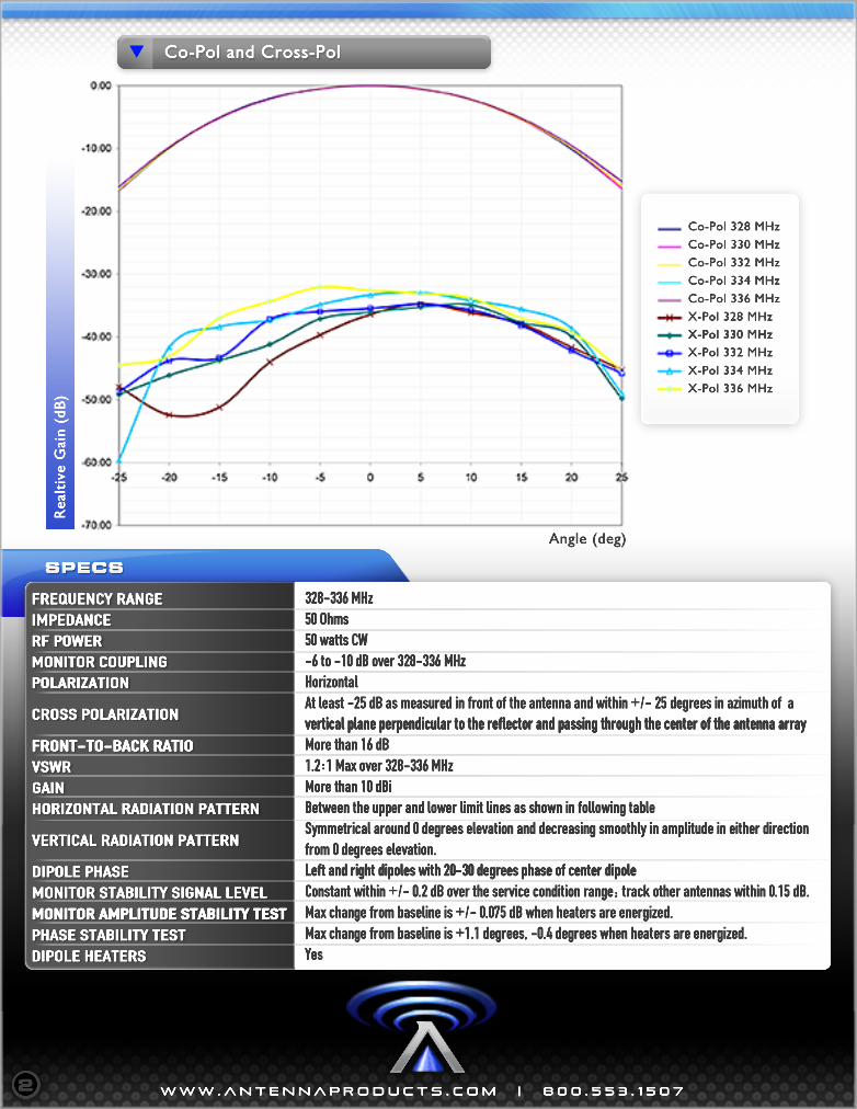
Co-Pol and Cross-Pol
2
Realtive Gain (dB)
Angle (deg)
SPECS
328-336 MHz50 Ohms50 watts CW-6 to -10 dB over 328-336 MHzHorizontalAt least -25 dB as measured in front of the antenna and within +/- 25 degrees in azimuth of avertical plane perpendicular to the reflector and passing through the center of the antenna arrayvertical plane perpendicular to the reflector and passing through the center of the antenna arrayMore than 16 dB1.2:1 Max over 328-336 MHzMore than 10 dBiBetween the upper and lower limit lines as shown in following tableSymmetrical around 0 degrees elevation and decreasing smoothly in amplitude in either directionfrom 0 degrees elevation.Left and right dipoles with 20-30 degrees phase of center dipoleLeft and right dipoles with 20-30 degrees phase of center dipoleConstant within +/- 0.2 dB over the service condition range; track other antennas within 0.15 dB.Max change from baseline is +/- 0.075 dB when heaters are energized.Max change from baseline is +1.1 degrees, -0.4 degrees when heaters are energized.Yes
FREQUENCY RANGEIMPEDANCE RF POWER MONITOR COUPLINGPOLARIZATION
CROSS POLARIZATION
FRONT-TO-BACK RATIOFRONT-TO-BACK RATIOVSWRGAINHORIZONTAL RADIATION PATTERN
VERTICAL RADIATION PATTERN
DIPOLE PHASEMONITOR STABILITY SIGNAL LEVELMONITOR AMPLITUDE STABILITY TESTMONITOR AMPLITUDE STABILITY TESTPHASE STABILITY TESTDIPOLE HEATERS
Co-Pol 328 MHz
Co-Pol 330 MHz
Co-Pol 332 MHz
Co-Pol 334 MHz
Co-Pol 336 MHz
X-Pol 328 MHz
X-Pol 330 MHzX-Pol 330 MHz
X-Pol 332 MHz
X-Pol 334 MHz
X-Pol 336 MHz
Aw w w .a n ten n a pro d u cts .co m | 800.553.1507
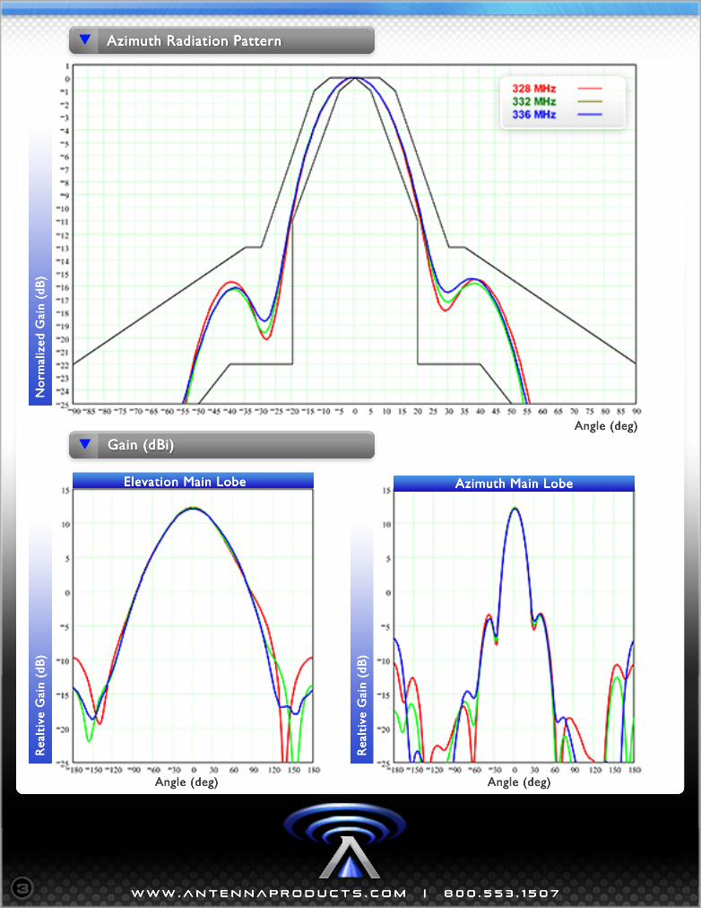
Realtive Gain (dB)
Realtive Gain (dB)
3
Normalized Gain (dB)
Angle (deg)
Angle (deg)Angle (deg)
Azimuth Main LobeElevation Main Lobe
Gain (dBi)
Azimuth Radiation Pattern