Embed Size (px)
Citation preview


Allied Machine & Engineering Corp.2
Allied Machine & Engineering Corp.120 Deeds Drive, Dover, Ohio 44622Telephone: (330) 343-4283 Toll Free USA & Canada: (800) 321-5537Fax: (330) 602-3400 Toll Free USA & Canada: (800) 223-5140International Country Code: 01Website Address: www.alliedmachine.comEmail Address: [email protected]
Our focus on product excellence, service to the customer, respect for the individual, and competitive advantage, enables us to deliver outstanding results in a diverse range of manufacturing, production and process engineering industries.
As a result, Allied high performance tooling is helping countless businesses across the world to produce better products with greater accuracy, increased speed and higher quality.
Precision, performance and productivity are core features of Allied tooling and our commitment to innovation in all aspects of hole making technology means we continually set new industry standards in production efficiency, tool life, and manufacturing cost improvements.
This product catalog provides detailed information on products in a comprehensive, easy to use, and informative single source reference guide. However, we recognize that every company’s needs are unique, which is why our customer service and technical support team are always available to provide help and advice, should you need it.
Whatever your need, Allied Machine & Engineering Corp. delivers high performance tooling on the cutting edge.
ALLIED MACHINE & ENGINEERING CORP.
WARNINGTool failure during use can cause serious injury. Follow safety precautions and instructions that accompany machinery and all tools.
Wear safety glasses and appropriate safety equipment at all times when machinery is operating.

Allied Machine & Engineering Corp. 3
Structural Steel T-A®
Allied Machine & Engineering Corp. 3
Structural Steel T-A®
Table of Contents
Structural Steel T-A® Inserts (TiAlN) Page 4
Structural Steel T-A® Inserts (AM200®) Page 5
Structural Steel Holders 0 and 0.5 Series Page 6
Structural Steel Holders 1 and 1.5 Series Pages 7-8
Structural Steel Holders 2 and 2.5 Series Page 9
Structural Steel Holders 3 Series Page 10
Structural Steel T-A® Deep Hole Drilling Guidelines Page11
Structural Steel T-A® Speeds and Feeds (Inch) Page 12
Structural Steel T-A® Speeds and Feeds (Metric) Page 13
Test and Demo Form Page 14
Warranty Page 15
Made in the USASAFETY ALERT
This triangle is a safety alert symbol. It alerts you to potential safety hazards that can cause tool failure and serious injury.When you see this symbol in the catalog, look for a related safety message that may be near this triangle or referred to in the nearby text.
There are safety signal words also used in the catalog. Safety messages follow these words.WARNINGWARNING (shown above) means that failure to follow the precautions in this message could result in tool failure and serious injury.
NOTE and IMPORTANT are also used. These are important that you read and follow but are not safety-related.
Visit www.alliedmachine.com for the most up-to-date information and procedures.
Your safety and the safety of others is very important. This catalog contains important safety messages. Always read and follow all safety precautions.
Allied Machine & Engineering Corp.4
Series Material
A (Diameter) B Item Number, Coating, and Availability
Fractional Equivalent (mm) (Inch) Thickness
Thin Wall TiAlN �
Notch Point® TiAlN �
150o Structural
Steel �
0
Super Cobalt
- 14,00 0.5512
1/8”
150A-14-TW m 150A-14-NP m 150A-14-SS m
9/16” 14,29 0.5625 150A-0018-TW m 150A-0018-NP m 150A-0018-SS m
5/8” 15,88 0.6250 150A-0020-TW m 150A-0020-NP m 150A-0020-SS m
- 16,00 0.6299 150A-16-TW m 150A-16-NP m 150A-16-SS m
11/16” 17,46 0.6875 150A-0022-TW m 150A-0022-NP m 150A-0022-SS m
1
- 18,00 0.7087
5/32”
151A-18-TW m 151A-18-NP m 151A-18-SS m
13/16” 20,64 0.8125 151A-0026-TW m 151A-0026-NP m 151A-0026-SS m
- 22,00 0.8661 151A-22-TW m 151A-22-NP m 151A-22-SS m
7/8” 22,23 0.8750 151A-0028-TW m 151A-0028-NP m 151A-0028-SS m
15/16” 23,81 0.9375 151A-0030-TW m 151A-0030-NP m 151A-0030-SS m
- 24,00 0.9449 151A-24-TW m 151A-24-NP m 151A-24-SS m
2
1” 25,40 1.0000
3/16”
152A-0100-TW m 152A-0100-NP m 152A-0100-SS m
- 26,00 1.0236 152A-26-TW m 152A-26-NP m 152A-26-SS m
1-1/16” 26,99 1.0625 152A-0102-TW m 152A-0102-NP m 152A-0102-SS m
- 27,00 1.0630 152A-27-TW m 152A-27-NP m 152A-27-SS m
1-1/8” 28,58 1.1250 152A-0104-TW m 152A-0104-NP m 152A-0104-SS m
1-3/16” 30,16 1.1875 152A-0106-TW m 152A-0106-NP m 152A-0106-SS m
- 31,00 1.2205 152A-31-TW m 152A-31-NP m 152A-31-SS m
1-1/4” 31,75 1.2500 152A-0108-TW m 152A-0108-NP m 152A-0108-SS m
- 33,00 1.2992 152A-33-TW m 152A-33-NP m 152A-33-SS m
1-5/16” 33,34 1.3125 152A-0110-TW m 152A-0110-NP m 152A-0110-SS m
1-3/8” 34,93 1.3750 152A-0112-TW m 152A-0112-NP m 152A-0112-SS m
31-7/16” 36,51 1.4375
1/4”
153A-0114-TW m 153A-0114-NP m 153A-0114-SS m
1-1/2” 38,10 1.5000 153A-0116-TW m 153A-0116-NP m 153A-0116-SS m
- 39,00 1.5354 153A-39-TW m 153A-39-NP m 153A-39-SS m
1-9/16” 39,69 1.5625 153A-0118-TW m 153A-0118-NP m 153A-0118-SS m
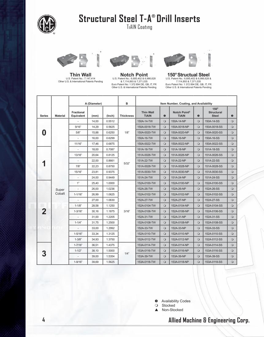
Thin WallU.S. Patent No.: 7,147,414
Other U.S. & International Patents Pending
Notch PointU.S. Patent No.: 6,685,402 & 6,986,628
& 7,114,893 & 7,371,035Euro Patent No: 1 372 894 DE, GB, IT, FROther U.S. & International Patents Pending
150o Structual SteelU.S. Patent No.: 6,685,402 & 6,986,628 &
7.114,893 & 7,371,035Euro Patent No: 1 372 894 DE, GB, IT, FROther U.S. & International Patents Pending
Structural Steel T-A® Drill InsertsTiAlN Coating
� Availability Codesm Stockedp Non-Stocked

Allied Machine & Engineering Corp. 5
Structural Steel T-A®
Series Material
A (Diameter) B Item Number, Coating, and Availability
Fractional Equivalent (mm) (Inch) Thickness
Thin Wall TiAlN �
Notch Point® TiAlN �
150o Structural
Steel �
0
Super Cobalt
- 14,00 0.5512
1/8”
150A-14-TW m 150A-14-NP m 150A-14-SS m
9/16” 14,29 0.5625 150A-0018-TW m 150A-0018-NP m 150A-0018-SS m
5/8” 15,88 0.6250 150A-0020-TW m 150A-0020-NP m 150A-0020-SS m
- 16,00 0.6299 150A-16-TW m 150A-16-NP m 150A-16-SS m
11/16” 17,46 0.6875 150A-0022-TW m 150A-0022-NP m 150A-0022-SS m
1
- 18,00 0.7087
5/32”
151A-18-TW m 151A-18-NP m 151A-18-SS m
13/16” 20,64 0.8125 151A-0026-TW m 151A-0026-NP m 151A-0026-SS m
- 22,00 0.8661 151A-22-TW m 151A-22-NP m 151A-22-SS m
7/8” 22,23 0.8750 151A-0028-TW m 151A-0028-NP m 151A-0028-SS m
15/16” 23,81 0.9375 151A-0030-TW m 151A-0030-NP m 151A-0030-SS m
- 24,00 0.9449 151A-24-TW m 151A-24-NP m 151A-24-SS m
2
1” 25,40 1.0000
3/16”
152A-0100-TW m 152A-0100-NP m 152A-0100-SS m
- 26,00 1.0236 152A-26-TW m 152A-26-NP m 152A-26-SS m
1-1/16” 26,99 1.0625 152A-0102-TW m 152A-0102-NP m 152A-0102-SS m
- 27,00 1.0630 152A-27-TW m 152A-27-NP m 152A-27-SS m
1-1/8” 28,58 1.1250 152A-0104-TW m 152A-0104-NP m 152A-0104-SS m
1-3/16” 30,16 1.1875 152A-0106-TW m 152A-0106-NP m 152A-0106-SS m
- 31,00 1.2205 152A-31-TW m 152A-31-NP m 152A-31-SS m
1-1/4” 31,75 1.2500 152A-0108-TW m 152A-0108-NP m 152A-0108-SS m
- 33,00 1.2992 152A-33-TW m 152A-33-NP m 152A-33-SS m
1-5/16” 33,34 1.3125 152A-0110-TW m 152A-0110-NP m 152A-0110-SS m
1-3/8” 34,93 1.3750 152A-0112-TW m 152A-0112-NP m 152A-0112-SS m
31-7/16” 36,51 1.4375
1/4”
153A-0114-TW m 153A-0114-NP m 153A-0114-SS m
1-1/2” 38,10 1.5000 153A-0116-TW m 153A-0116-NP m 153A-0116-SS m
- 39,00 1.5354 153A-39-TW m 153A-39-NP m 153A-39-SS m
1-9/16” 39,69 1.5625 153A-0118-TW m 153A-0118-NP m 153A-0118-SS m
Series Material
A (Diameter) B Item Number, Coating, and Availability
Fractional Equivalent (mm) (Inch)
Thick-ness
Thin Wall AM200® �
Notch Point® AM200® �
150o Structural
Steel AM200® �
GEN2 T-A® HSS
AM200® �
GEN2 T-A® CarbideAM200® �
0
Super Cobalt
- 14,00 0.5512
1/8”
150H-14-TW m 150H-14-NP m 150H-14-SS m 450H-14 m 4C10H-14 m
9/16” 14,29 0.5625 150H-0018-TW m 150H-0018-NP m 150H-0018-SS m 450H-0018 m 4C10H-0018 m
5/8” 15,88 0.6250 150H-0020-TW m 150H-0020-NP m 150H-0020-SS m 450H-0020 m 4C10H-0020 m
- 16,00 0.6299 150H-16-TW m 150H-16-NP m 150H-16-SS m 450H-16 m 4C10H-16 m
11/16” 17,46 0.6875 150H-0022-TW m 150H-0022-NP m 150H-0022-SS m 450H-0022 m 4C10H-0022 m
1
- 18,00 0.7087
5/32”
151H-18-TW m 151H-18-NP m 151H-18-SS m 451H-18 m 4C11H-18 m
13/16” 20,64 0.8125 151H-0026-TW m 151H-0026-NP m 151H-0026-SS m 451H-0026 m 4C11H-0026 m
21,00 0.8268 151H-21-TW m 151H-21-NP m 151H-21-SS m 451H-21 m 451H-21 m
- 22,00 0.8661 151H-22-TW m 151H-22-NP m 151H-22-SS m 451H-22 m 4C11H-22 m
7/8” 22,23 0.8750 151H-0028-TW m 151H-0028-NP m 151H-0028-SS m 451H-0028 m 4C11H-0028 m
15/16” 23,81 0.9375 151H-0030-TW m 151H-0030-NP m 151H-0030-SS m 451H-0030 m 4C11H-0030 m
- 24,00 0.9449 151H-24-TW m 151H-24-NP m 151H-24-SS m 451H-24 m 4C11H-24 m
2
1” 25,40 1.0000
3/16”
152H-0100-TW m 152H-0100-NP m 152H-0100-SS m 452H-0100 m 4C12H-0100 m
- 26,00 1.0236 152H-26-TW m 152H-26-NP m 152H-26-SS m 452H-26 m 4C12H-26 m
1-1/16” 26,99 1.0625 152H-0102-TW m 152H-0102-NP m 152H-0102-SS m 452H-0102 m 4C12H-0102 m
- 27,00 1.0630 152H-27-TW m 152H-27-NP m 152H-27-SS m 452H-27 m 4C12H-27 m
1-1/8” 28,58 1.1250 152H-0104-TW m 152H-0104-NP m 152H-0104-SS m 452H-0104 m 4C12H-0104 m
1-3/16” 30,16 1.1875 152H-0106-TW m 152H-0106-NP m 152H-0106-SS m 452H-0106 m 4C12H-0106 m
- 31,00 1.2205 152H-31-TW m 152H-31-NP m 152H-31-SS m 452H-31 m 4C12H-31 m
1-1/4” 31,75 1.2500 152H-0108-TW m 152H-0108-NP m 152H-0108-SS m 452H-0108 m 4C12H-0108 m
- 33,00 1.2992 152H-33-TW m 152H-33-NP m 152H-33-SS m 452H-33 m 4C12H-33 m
1-5/16” 33,34 1.3125 152H-0110-TW m 152H-0110-NP m 152H-0110-SS m 452H-0110 m 4C12H-0110 m
1-3/8” 34,93 1.3750 152H-0112-TW m 152H-0112-NP m 152H-0112-SS m 452H-0112 m 4C12H-0112 m
31-7/16” 36,51 1.4375
1/4”
153H-0114-TW m 153H-0114-NP m 153H-0114-SS m 453H-0114 m - -
1-1/2” 38,10 1.5000 153H-0116-TW m - m 153H-0116-SS m 453H-0116 m - -
- 39,00 1.5354 153H-39-TW m - m 153H-39-SS m 453H-39 m - -
1-9/16” 39,69 1.5625 153H-0118-TW m - m 153H-0118-SS m 453H-0118 m - -
Thin WallU.S. Patent No.: 7,147,414
Other U.S. & International Patents Pending
Notch PointU.S. Patent No.: 6,685,402 & 6,986,628
& 7,114,893 & 7,371,035Euro Patent No: 1 372 894 DE, GB, IT, FROther U.S. & International Patents Pending
150o Structural SteelU.S. Patent No.: 6,685,402 & 6,986,628 &
7.114,893 & 7,371,035Euro Patent No: 1 372 894 DE, GB, IT, FROther U.S. & International Patents Pending
GEN2 T-A®
U.S. Patent No.: 6,685,402 & 6,986,628 & 7,011,478 & 7,018,145 & 7,144,893 &
7,241,089 & 7,371,035Euro Patent No.: 1 372 894 DE,GB, IT, FR
Korean Patent No.: 764140Other U.S. & International Patents Pending
Structural Steel T-A® Drill InsertsAM200® Coating
� Availability Codesm Stockedp Non-Stocked

Allied Machine & Engineering Corp.6
Structural Steel Holders0 and 0.5 Series Holders
* If using Structural Steel Holder with Notch Point®, GEN2 T-A®, or 150o Structural Steel T-A® Drill Insert Geometry.TTC = Through Tang CoolantTSC = Through Shank Coolant
Length Item Number
A B C D *D2 E F G HDrill Insert
RangeMax. Drill
DepthBody
LengthRef.
LengthRef.
LengthOverall Length MT
Coolant Inlet Style
Short 22000S-003IS036 9/16” 1-3/8” 2-3/16” 2-35/64” 2-31/64” 6-1/16” #3 TTC TSC
Short 22005S-003IS040 5/8” 1-3/8” 2-3/16” 2-35/64” 2-31/64” 6-1/16” #3 TTC TSC
Short 22005S-003IS044 11/16” 1-3/8” 2-3/16” 2-35/64” 2-31/64” 6-1/16” #3 TTC TSC
Metric (mm)Short 22000S-003IS036 14 35 56 64.7 63.1 154 #3 TTC TSC
Short 22000S-003IS040 16 35 56 64.7 63.1 154 #3 TTC TSC
Short 22000S-003IS044 17.5 35 56 64.7 63.1 154 #3 TTC TSC
Length Item Number
A B C D *D2 E F G H
Drill Insert Range
Max. Drill Depth
Body Length
Ref. Length
Ref. Length
Overall Length MT
CoolantInlet Style
Standard 24000H-003IS036 9/16” 2-1/2” 3-5/16” 3-43/64” 3-39/64” 7-3/16” #3 TTC TSC
Standard 24005H-003IS040 5/8” 2-1/2” 3-5/16” 3-43/64” 3-39/64” 7-3/16” #3 TTC TSC
Standard 24005H-003IS044 11/16” 2-1/2” 3-5/16” 3-43/64” 3-39/64” 7-3/16” #3 TTC TSC
Extended 25000H-003IS036 9/16” 6-1/2” 9-7/16” 9-51/64” 9-19/32” 13-5/64” #3 TTC TSC
Extended 25005H-003IS044 11/16” 6-1/2” 9-7/16” 9-51/64” 9-19/32” 13-5/64” #3 TTC TSC
Metric (mm)
Standard 24000H-003IS036 14 64 84 93.3 91.7 183 #3 TTC TSC
Standard 24005H-003IS040 16 64 84 93.3 91.7 183 #3 TTC TSC
Standard 24005H-003IS044 17.5 64 84 93.3 91.7 183 #3 TTC TSC
Extended 25000H-003IS036 14 165 240 248.8 243.7 338 #3 TTC TSC
Extended 25005H-003IS044 17.5 165 240 248.8 243.7 338 #3 TTC TSC
Structural Steel Taper Shank Straight Flute Holders
Structural Steel Taper Shank Helical Flute Holders
H
F
White 0 SeriesGrey 0.5 Series
Refer to Speed and Feed charts for recommended adjustments to speeds and feeds. Refer to page 11 for Deep Hole Drilling Guidelines in Technical Reference section of catalog. Visit www.alliedmachine.com/deepholeguidelines.aspx for the most up-to-date information and procedures. Factory technical assistance is available for your specific applications through our Application Engineering Team.
WARNING

Allied Machine & Engineering Corp. 7
Structural Steel T-A®
� Availability Codesm Stockedp Non-Stocked
* If using Structural Steel Holder with Notch Point®, GEN2 T-A®, or 150o Structural Steel T-A® Drill Insert Geometry.TTC = Through Tang CoolantTSC = Through Shank Coolant
Structural Steel Holders1 and 1.5 Series Holders
Length Item Number
A B C D *D2 E F G H
Drill Insert Range
Max. Drill Depth
Body Length
Ref. Length
Ref. Length
Overall Length MT
Coolant Inlet Style
Short 22010S-003IS045 18mm 2-3/4” 3-7/8” 4-17/64” 4-13/64” 7-3/4” #3 TTC TSC
Short 22010S-004IS045 18mm 2-3/4” 3-7/8” 4-21/64” 4-17/64” 8-3/4” #4 TTC TSC
Short 22010S-003IS052 13/16” 2-3/4” 3-7/8” 4-17/64” 4-13/64” 7-3/4” #3 TTC TSC
Short 22010S-004IS052 13/16” 2-3/4” 3-7/8” 4-21/64” 4-17/64” 8-3/4” #4 TTC TSC
Short 22015S-003IS056 7/8” 2-3/4” 3-7/8” 4-17/64” 4-13/64” 7-3/4” #3 TTC TSC
Short 22015S-004IS056 7/8” 2-3/4” 3-7/8” 4-21/64” 4-17/64” 8-3/4” #4 TTC TSC
Short 22015S-003IS060 15/16” 2-3/4” 3-7/8” 4-17/64” 4-13/64” 7-3/4” #3 TTC TSC
Short 22015S-004IS060 15/16” 2-3/4” 3-7/8” 4-21/64” 4-17/64” 8-3/4” #4 TTC TSC
Metric (mm)Short 22010S-003IS045 18 70 98 108.4 106.8 197 #3 TTC TSC
Short 22010S-004IS045 18 70 98 109.9 108.3 222 #4 TTC TSC
Short 22010S-003IS052 21 70 98 108.4 106.8 197 #3 TTC TSC
Short 22010S-004IS052 21 70 98 109.9 108.3 222 #4 TTC TSC
Short 22015S-003IS056 22 70 98 108.4 106.8 197 #3 TTC TSC
Short 22015S-004IS056 22 70 98 109.9 108.3 222 #4 TTC TSC
Short 22015S-003IS060 24 70 98 108.4 106.8 197 #3 TTC TSC
Short 22015S-004IS060 24 70 98 109.9 108.3 222 #4 TTC TSC
Structural Steel Taper Shank Straight Flute Holders
White 1 SeriesGrey 1.5 Series

Allied Machine & Engineering Corp.8
Structural Steel Holders1 and 1.5 Series Holders
Refer to Speed and Feed charts for recommended reductions in speeds and feedsRefer to page C108 for Deep Hole Drilling Guidelines in Technical Reference section of catalog
Refer to Speed and Feed charts for recommended adjustments to speeds and feeds. Refer to page 11 for Deep Hole Drilling Guidelines in Technical Reference section of catalog. Visit www.alliedmachine.com/deepholeguidelines.aspx for the most up-to-date information and procedures. Factory technical assistance is available for your specific applications through our Application Engineering Team.
WARNING
Length Item Number
A B C D *D2 E F G H
Drill Insert Range
Max. Drill Depth
Body Length
Ref. Length
Ref. Length
Overall Length MT
Coolant Inlet Style
Standard 24010H-003IS045 18mm 4-3/4” 5-7/8” 6-17/64” 6-13/64” 9-3/4” #3 TTC TSC
Standard 24010H-004IS045 18mm 4-3/4” 5-7/8” 6-21/64” 6-17/64” 10-3/4” #4 TTC TSC
Standard 24010H-003IS052 13/16” 4-3/4” 5-7/8” 6-17/64” 6-13/64” 9-3/4” #3 TTC TSC
Standard 24010H-004IS052 13/16” 4-3/4” 5-7/8” 6-21/64” 6-17/64” 10-3/4” #4 TTC TSC
Standard 24015H-003IS056 7/8” 4-3/4” 5-7/8” 6-17/64” 6-13/64” 9-3/4” #3 TTC TSC
Standard 24015H-004IS056 7/8” 4-3/4” 5-7/8” 6-21/64” 6-17/64” 10-3/4” #4 TTC TSC
Standard 24015H-003IS060 15/16” 4-3/4” 5-7/8” 6-17/64” 6-13/64” 9-3/4” #3 TTC TSC
Standard 24015H-004IS060 15/16” 4-3/4” 5-7/8” 6-21/64” 6-17/64” 10-3/4” #4 TTC TSC
Extended 25010H-003IS045 18mm 6-1/2” 9-11/32” 9-47/64” 9-1/2” 13-7/32” #3 TTC TSC
Extended 25010H-003IS052 13/16” 6-1/2” 9-11/32” 9-47/64” 9-1/2” 13-7/32” #3 TTC TSC
Extended 25010H-004IS052 13/16” 6-1/2” 9-9/32” 9-47/64” 9-43/64” 14-5/32” #4 TTC TSC
Extended 25015H-003IS060 15/16” 6-1/2” 9-11/32” 9-47/64” 9-15/32” 13-7/32” #3 TTC TSC
Extended 25015H-004IS060 15/16” 6-1/2” 9-9/32” 9-47/64” 9-43/64” 14-5/32” #4 TTC TSC
Long 26010H-004IS052 13/16” 6-1/2” 15-25/32” 16-15/64” 16-11/64” 20-21/32” #4 TTC TSC
Long 26015H-004IS060 15/16” 6-1/2” 15-13/16” 16-17/64” 16-13/64” 20-11/16” #4 TTC TSC
Metric (mm)Standard 24010H-003IS045 18 121 149 159.2 157.6 248 #3 TTC TSC
Standard 24010H-004IS045 18 121 149 160.8 159.2 273 #4 TTC TSC
Standard 24010H-003IS052 21 121 149 159.2 157.6 248 #3 TTC TSC
Standard 24010H-004IS052 21 121 149 160.8 159.2 273 #4 TTC TSC
Standard 24015H-003IS056 22 121 149 159.2 157.6 248 #3 TTC TSC
Standard 24015H-004IS056 22 121 149 160.8 159.2 273 #4 TTC TSC
Standard 24015H-003IS060 24 121 149 159.2 157.6 248 #3 TTC TSC
Standard 24015H-004IS060 24 121 149 160.8 159.2 273 #4 TTC TSC
Extended 25010H-003IS045 18 165 237 247.3 241.3 336 #3 TTC TSC
Extended 25010H-003IS052 22 165 237 247.3 241.3 336 #3 TTC TSC
Extended 25010H-004IS052 22 165 236 247.3 245.7 384 #4 TTC TSC
Extended 25015H-003IS060 24 165 237 247.3 234.5 336 #3 TTC TSC
Extended 25015H-004IS060 24 165 236 247.3 245.7 384 #4 TTC TSC
Long 26010H-004IS052 22 165 401 412.4 410.8 525 #4 TTC TSC
Long 26015H-004IS060 24 165 401 413.1 411.6 525 #4 TTC TSC
Structural Steel Taper Shank Helical Flute Holders
White 1 SeriesGrey 1.5 Series
* If using Structural Steel Holder with Notch Point®, GEN2 T-A®, or 150o Structural Steel T-A® Drill Insert Geometry.TTC = Through Tang CoolantTSC = Through Shank Coolant

Allied Machine & Engineering Corp. 9
Structural Steel T-A®
Structural Steel Holders2 and 2.5 Series Holders
Length Item Number
A B C D *D2 E F G H
Drill Insert Range
Max. Drill Depth
Body Length
Ref. Length
Ref. Length
Overall Length MT
Coolant Inlet Style
Short 22020S-004IS100 1” - 1-3/8” 3-3/8” 4-1/2” 4-63/64” 4-57/64” 9-3/8” #4 TTC TSC
Short 22025S-004IS112 1-3/16” - 1-3/8” 3-3/8” 4-1/2” 4-63/64” 4-57/64” 9-3/8” #4 TTC TSC
Metric (mm)
Short 22020S-004IS100 26 86 114 126.6 124.2 238 #4 TTC TSC
Short 22025S-004IS112 31 86 114 126.6 124.2 238 #4 TTC TSC
Structural Steel Taper Shank Helical Flute Holders
Length Item Number
A B C D *D2 E F G H
Drill Insert Range
Max. Drill Depth
Body Length
Ref. Length
Ref. Length
Overall Length MT
Coolant Inlet Style
Standard 24020H-004IS100 1” - 1-3/8” 5-3/8” 6-1/2” 6-63/64” 6-57/64” 11-3/8” #4 TTC TSC
Standard 24025H-004IS112 1-3/16” - 1-3/8” 5-3/8” 6-1/2” 6-63/64” 6-57/64” 11-3/8” #4 TTC TSC
Extended 25020H-003IS100 1” - 1-3/8” 6-1/2 7-11/32” 9-3/4” 9-29/64” 13-7/32” #3 TTC TSC
Extended 25020H-004IS100 1” - 1-3/8” 6-1/2 7-9/32” 9-3/4” 9-43/64” 14-5/32” #4 TTC TSC
Long 26020H-004IS100 1” - 1-3/8” 6-1/2 16” 16-15/32” 16-25/64” 20-7/8” #4 TTC TSC
Metric (mm)
Standard 24020H-004IS100 26 137 165 177.4 175.0 289 #4 TTC TSC
Standard 24025H-004IS112 31 137 165 177.4 175.0 289 #4 TTC TSC
Extended 25020H-003IS100 26 165 237 247.7 240.1 336 #3 TTC TSC
Extended 25020H-004IS100 26 165 237 247.7 245.7 360 #4 TTC TSC
Long 26020H-004IS100 26 165 406 418.3 416.3 530 #4 TTC TSC
Structural Steel Taper Shank Helical Flute Holders
*Dimension if using a Structural Steel Holder with Notch Point® T-A® Drill Insert Geometry.
*Dimension if using a Structural Steel Holder with Notch Point® T-A® Drill Insert Geometry.
H
F
Refer to Speed and Feed charts for recommended adjustments to speeds and feeds. Refer to page 11 for Deep Hole Drilling Guidelines in Technical Reference section of catalog. Visit www.alliedmachine.com/deepholeguidelines.aspx for the most up-to-date information and procedures. Factory technical assistance is available for your specific applications through our Application Engineering Team.
WARNING
White 2 SeriesGrey 2.5 Series
* If using Structural Steel Holder with Notch Point®, GEN2 T-A®, or 150o Structural Steel T-A® Drill Insert Geometry.TTC = Through Tang CoolantTSC = Through Shank Coolant
Allied Machine & Engineering Corp.10
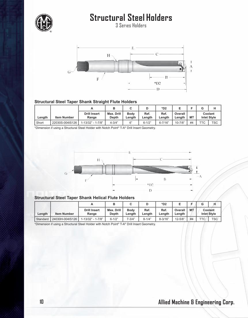
Structural Steel Holders3 Series Holders
Length Item Number
A B C D *D2 E F G HDrill Insert
RangeMax. Drill
DepthBody
LengthRef.
LengthRef.
LengthOverall Length MT
Coolant Inlet Style
Short 22030S-004IS126 1-13/32” - 1-7/8” 4-3/4” 6” 6-1/2” 6-7/16” 10-7/8” #4 TTC TSC
Structural Steel Taper Shank Straight Flute Holders
Length Item Number
A B C D *D2 E F G H
Drill Insert Range
Max. Drill Depth
Body Length
Ref. Length
Ref. Length
Overall Length
MT Coolant Inlet Style
Standard 24030H-004IS126 1-13/32” - 1-7/8” 6-1/2” 7-3/4” 8-1/4” 8-3/16” 12-5/8” #4 TTC TSC
*Dimension if using a Structural Steel Holder with Notch Point® T-A® Drill Insert Geometry.
*Dimension if using a Structural Steel Holder with Notch Point® T-A® Drill Insert Geometry.
Structural Steel Taper Shank Helical Flute Holders
H
F

Allied Machine & Engineering Corp. 11
Structural Steel T-A®
Structural Steel T-A®
Deep Hole Drilling Guidelines
WARNINGTool failure can cause serious injury. To prevent: - When using holders without support bushing, use a short T-A holder to establish an initial hole that is a minimum of 2 diameters deep. - Do not rotate tool holders more than 50 RPM unless it is engaged with workpiece or fixtureVisit www.alliedmachine.com/deepholeguidelines.aspx for the most up-to-date information and procedures. Factory technical assistance is also available for your specific applications.
Allied Machine & Engineering Corp. 11
Allied Machine & Engineering Corp.12
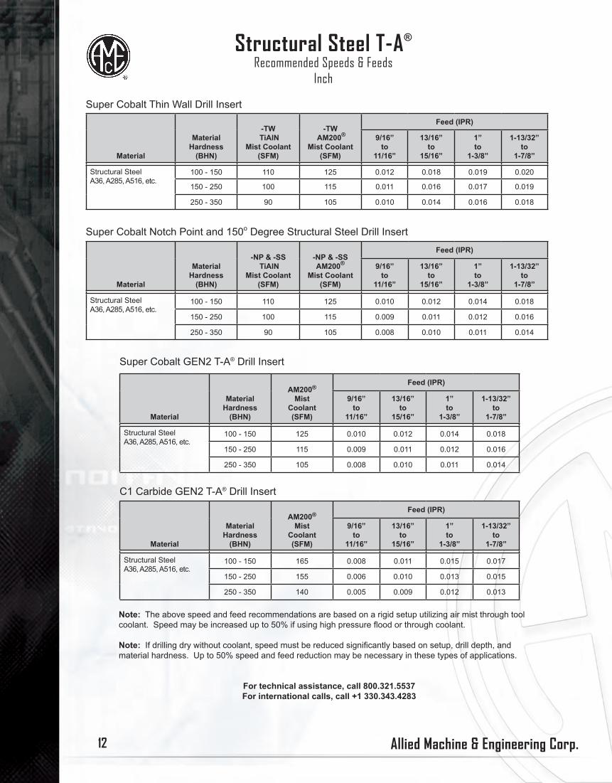
Structural Steel T-A®
Recommended Speeds & FeedsInch
Note: The above speed and feed recommendations are based on a rigid setup utilizing air mist through tool coolant. Speed may be increased up to 50% if using high pressure flood or through coolant.
Note: If drilling dry without coolant, speed must be reduced significantly based on setup, drill depth, and material hardness. Up to 50% speed and feed reduction may be necessary in these types of applications.
For technical assistance, call 800.321.5537For international calls, call +1 330.343.4283
Super Cobalt Thin Wall Drill Insert
Material
MaterialHardness
(BHN)
-TW TiAlN
Mist Coolant (SFM)
-TW AM200®
Mist Coolant (SFM)
Feed (IPR)
9/16”to
11/16”
13/16”to
15/16”
1”to
1-3/8”
1-13/32”to
1-7/8”
Structural SteelA36, A285, A516, etc.
100 - 150 110 125 0.012 0.018 0.019 0.020
150 - 250 100 115 0.011 0.016 0.017 0.019
250 - 350 90 105 0.010 0.014 0.016 0.018
Super Cobalt Notch Point and 150o Degree Structural Steel Drill Insert
Material
MaterialHardness
(BHN)
-NP & -SS TiAlN
Mist Coolant (SFM)
-NP & -SSAM200®
Mist Coolant (SFM)
Feed (IPR)
9/16”to
11/16”
13/16”to
15/16”
1”to
1-3/8”
1-13/32”to
1-7/8”
Structural SteelA36, A285, A516, etc.
100 - 150 110 125 0.010 0.012 0.014 0.018
150 - 250 100 115 0.009 0.011 0.012 0.016
250 - 350 90 105 0.008 0.010 0.011 0.014
Super Cobalt GEN2 T-A® Drill Insert
Material
MaterialHardness
(BHN)
AM200®
Mist Coolant(SFM)
Feed (IPR)
9/16”to
11/16”
13/16”to
15/16”
1”to
1-3/8”
1-13/32”to
1-7/8”
Structural SteelA36, A285, A516, etc.
100 - 150 125 0.010 0.012 0.014 0.018
150 - 250 115 0.009 0.011 0.012 0.016
250 - 350 105 0.008 0.010 0.011 0.014
C1 Carbide GEN2 T-A® Drill Insert
Material
MaterialHardness
(BHN)
AM200®
Mist Coolant(SFM)
Feed (IPR)
9/16”to
11/16”
13/16”to
15/16”
1”to
1-3/8”
1-13/32”to
1-7/8”
Structural SteelA36, A285, A516, etc.
100 - 150 165 0.008 0.011 0.015 0.017
150 - 250 155 0.006 0.010 0.013 0.015
250 - 350 140 0.005 0.009 0.012 0.013
Allied Machine & Engineering Corp. 13
Structural Steel T-A®
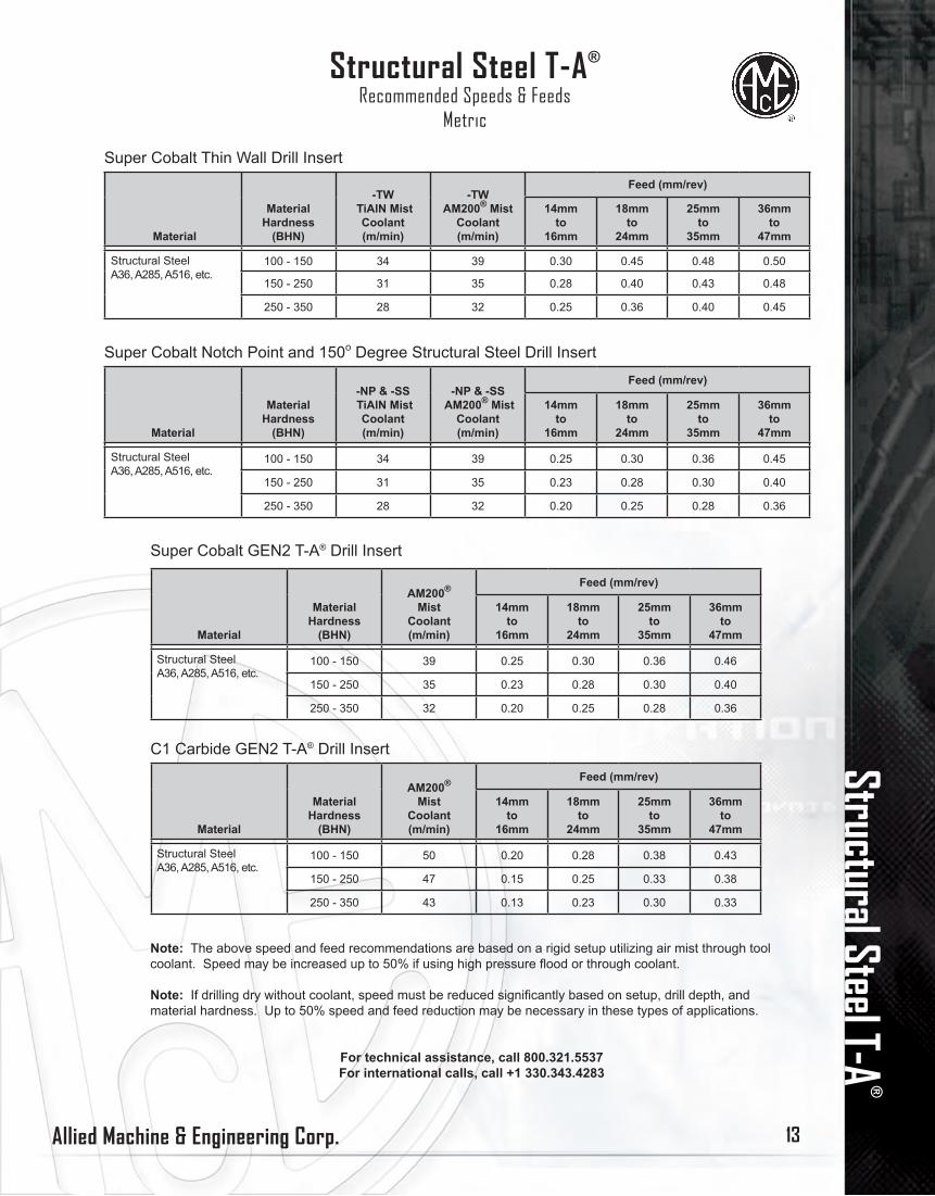
Super Cobalt Thin Wall Drill Insert
Material
MaterialHardness
(BHN)
-TW TiAlN Mist
Coolant (m/min)
-TWAM200® Mist
Coolant (m/min)
Feed (mm/rev)
14mmto
16mm
18mmto
24mm
25mmto
35mm
36mmto
47mm
Structural SteelA36, A285, A516, etc.
100 - 150 34 39 0.30 0.45 0.48 0.50
150 - 250 31 35 0.28 0.40 0.43 0.48
250 - 350 28 32 0.25 0.36 0.40 0.45
Super Cobalt Notch Point and 150o Degree Structural Steel Drill Insert
Material
MaterialHardness
(BHN)
-NP & -SS TiAlN Mist
Coolant (m/min)
-NP & -SS AM200® Mist
Coolant (m/min)
Feed (mm/rev)
14mmto
16mm
18mmto
24mm
25mmto
35mm
36mmto
47mm
Structural SteelA36, A285, A516, etc.
100 - 150 34 39 0.25 0.30 0.36 0.45
150 - 250 31 35 0.23 0.28 0.30 0.40
250 - 350 28 32 0.20 0.25 0.28 0.36
Super Cobalt GEN2 T-A® Drill Insert
Material
MaterialHardness
(BHN)
AM200®
Mist Coolant (m/min)
Feed (mm/rev)
14mmto
16mm
18mmto
24mm
25mmto
35mm
36mmto
47mm
Structural SteelA36, A285, A516, etc.
100 - 150 39 0.25 0.30 0.36 0.46
150 - 250 35 0.23 0.28 0.30 0.40
250 - 350 32 0.20 0.25 0.28 0.36
C1 Carbide GEN2 T-A® Drill Insert
Material
MaterialHardness
(BHN)
AM200®
Mist Coolant (m/min)
Feed (mm/rev)
14mmto
16mm
18mmto
24mm
25mmto
35mm
36mmto
47mm
Structural SteelA36, A285, A516, etc.
100 - 150 50 0.20 0.28 0.38 0.43
150 - 250 47 0.15 0.25 0.33 0.38
250 - 350 43 0.13 0.23 0.30 0.33
Note: The above speed and feed recommendations are based on a rigid setup utilizing air mist through tool coolant. Speed may be increased up to 50% if using high pressure flood or through coolant.
Note: If drilling dry without coolant, speed must be reduced significantly based on setup, drill depth, and material hardness. Up to 50% speed and feed reduction may be necessary in these types of applications.
For technical assistance, call 800.321.5537For international calls, call +1 330.343.4283
Structural Steel T-A®
Recommended Speeds & FeedsMetric
Allied Machine & Engineering Corp.14
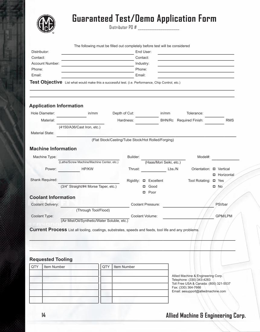
Guaranteed Test/Demo Application FormDistributor PO # ______________________
The following must be filled out completely before test will be consideredDistributor: End User:Contact: Contact:Account Number: Industry:Phone: Phone:Email: Email:
Test Objective List what would make this a successful test. (i.e. Performance, Chip Control, etc.)
Application InformationHole Diameter: in/mm Depth of Cut: in/mm Tolerance:
Material: Hardness: BHN/Rc Required Finish: RMS
(4150/A36/Cast Iron, etc.)Material State:
(Flat Stock/Casting/Tube Stock/Hot Rolled/Forging)
Machine InformationMachine Type: Builder: Model#:
(Lathe/Screw Machine/Machine Center, etc.) (Haas/Mori Seiki, etc.)
Power: HP/KW Thrust: Lbs./N Orientation: p Verticalp Horizontal
Shank Required: Rigidity: p Excellent Tool Rotating: p Yes (3/4” Straight/#4 Morse Taper, etc.) p Good p No
p PoorCoolant InformationCoolant Delivery: Coolant Pressure: PSI/bar
(Through Tool/Flood)Coolant Type: Coolant Volume: GPM/LPM
(Air Mist/Oil/Synthetic/Water Soluble, etc.)
Current Process List all tooling, coatings, substrates, speeds and feeds, tool life and any problems.
Requested ToolingQTY Item Number QTY Item Number
Allied Machine & Engineering Corp.Telephone: (330) 343-4283Toll Free USA & Canada: (800) 321-5537Fax: (330) 364-7666Email: [email protected]

Allied Machine & Engineering Corp. 15
Allied Machine & Engineering Corp. warrants to original equipment manufacturers, distributors, industrial and commercial users of its products, that each new product manufactured or supplied by Allied Machine shall be free from defects in material and workmanship.
Allied’s obligation under this warranty is limited to furnishing without additional charge a replacement or, at its option repairing or issuing credit for any product which shall within one year from the date of sale be returned freight prepaid to the plant designated by an Allied representative and which upon inspection is determined by Allied to be defective in materials or workmanship.
Complete information as to operating conditions, machine setup, and application of cutting fluid should accompany any product returned for inspection. The provisions of this warranty shall not apply to any Allied product which has been subjected to misuse, improper operating conditions, machine setup or application of cutting fluid or which has been repaired or altered if such repair or alteration in the judgement of Allied would adversely affect performance of the product.
THIS WARRANTY IS IN LIEU OF ALL OTHER WARRANTIES, EXPRESS OR IMPLIED, INCLUDING ANY IMPLIED WARRANTY OF MERCHANTABILITY OR FITNESS FOR A PARTICULAR PURPOSE. Allied shall have no liability or responsibility on any claim of any kind, whether in contract, tort or otherwise, for any loss or damage arising out of, connected with, or resulting from the manufacture, sale, delivery or use of any product sold hereunder, in excess of the cost of replacement or repair as provided herein. IN NO EVENT SHALL ALLIED MACHINE & ENGINEERING CORP. BE LIABLE FOR ANY SPECIAL INCIDENTAL OR CONSEQUENTIAL DAMAGES. Allied makes no other warranty, express or implied, except as set forth above, and Allied neither assumes nor authorizes any other person or entity to assume for it any other obligation or liability in connection with any of its products.
ALL PRICES, DELIVERIES, DESIGNS, AND MATERIALS ARE SUBJECT TO CHANGE WITHOUT NOTICE.
Allied Machine & Engineering Corp.120 Deeds Drive, Dover, Ohio 44622
Telephone: (330) 343-4283Toll Free USA & Canada: (800) 321-5537
Fax: (330) 602-3400Toll Free USA & Canada: (800) 223-5140
International Country Code: 01Website Address: www.alliedmachine.comEmail Address: [email protected]
All orders are processed through Allied’s computerized order entry and invoicing system. Please specify the correct item number as well as full description of the desired item(s) so we can process your order accurately and efficiently. Incorrect item numbers and/or descriptions will cause unnecessary delays and returns that are subject to a 10% restocking charge. Your assistance is critical if we are to achieve our goal of processing orders and shipping in stock items within 24 hours.
Ordering Instructions
Warranty