Embed Size (px)
Citation preview
Gaurang H Patel, Prof. Rohit B Patel, Prof.Sweta J Patel 8
International Journal of Emerging Trends in Electrical and Electronics (IJETEE – ISSN: 2320-9569) Vol. 3, Issue. 2, May-2013.
A Design & Comparative Analysis Of 320 Gb/sDWDM Optical Network With CSRZ, DRZ &
MDRZ Modulation FormatsGaurang H Patel, Prof. Rohit B Patel, Prof.Sweta J Patel
Abstract: This paper demonstrate design of 320 Gb/s Densewavelength division multiplexing optical network with optimizedmodulation format. In this paper, system is simulated with8-channels with data rate of 40 Gb/s. The system is simulatedusing different modulation formats and different dispersioncompensation techniques like pre, post and symmetricalcompensation. The optimized modulation format offer very highdispersion tolerance so due to this, it make possible to achievelonger distance communication. Among the different dispersioncompensation techniques, symmetrical compensation with MDRZmodulation format shows best performance in terms of highestQ-Factor and minimum BER.
Keywords: BER, Dispersion Compensating Fiber, DWDMNetwork, Modulation Formats, Q-Factor.
I. INTRODUCTIONIn today’s scenario demand for high bandwidth and high datarate is there because of growth in different technology likevideo on demand, use of internet, voice over IP, streamingvideo. Optical fiber fulfill this demand because it offer verylarge bandwidth so multiple channels can be transmittedthrough the common fiber using concept of wavelengthdivision multiplexing technique. DWDM technique offershigh spectral efficiency but performance is limited due to theproblem of dispersion and fiber nonlinearities. So theseproblem must be minimized to achieve better performance.Dispersion compensation is achieved using differenttechniques like dispersion compensating fiber, fiber bragggrating, optical phase conjugation and electrical equalizer.Among all these technique, dispersion compensation fiber isproposed for compensation of dispersion. In conventionaloptical fiber communication, return-to-zero and non-return tozero modulation formats are used. But NRZ and RZ are notefficient for DWDM network. So different modulationformats like carrier suppressed return to zero(CSRZ) andmodified duo-binary return to zero formats are proposed.
Gaurang H. Patel , Prof. Rohit B. Patel and prof. Sweta J. Patel are with U.V. Patel College of Engineering, Ganpat University, Kherva, Gujarat,E-mails:[email protected],[email protected],[email protected]
Bo-ning HU1, Wang Jing1, Wang Wei2 and Rui-meiZhao1 analyzed Fibres-optic dispersion and its effect onoptical transmission system. In this paper, three schemes(pre, post and symmetrical dispersion compensation) ofdispersion compensation with DCF are proposed.Symmetrical-compensation gives best result among all ofthese three [1].
M. I. Hayee and A. E. Willner describe the group velocitydispersion (GVD) and nonlinear effects, such as self- andcross-phase modulation (SPM/XPM) and four-wave mixing(FWM) in wavelength-division-multiplexed (WDM) systemsat 10 Gb/s that degrade the performance of the system. In thispaper, 10-Gb/s WDM systems that use pre-compensation,Post-compensation or dual-compensation of each channel tominimize dispersion and nonlinear effects is explained [2].
Anu Sheetal, AjayK.Sharma and R.S.Kaler describes thesimulative analysis of 40 Gb/s long haul DWDM system withultra high capacity has been carried out for carrier-suppressedreturn-to-zero (CSRZ), duo binary return-to-zero (DRZ) andmodified duo binary return-to-zero (MDRZ) modulationformats. The DWDM system has been analyzed for the pre,post and symmetrical dispersion compensation schemes inorder to find the optimum modulation format for a high bitrate optical transmission system [3].
Rajani, Raju Pal, Vishal Sharma investigate pre, post andsymmetrical-dispersion compensation methods for10/15Gb/s using different modulation formats like NRZ, RZand RZ Super gaussian using standard and dispersioncompensated fibers through computer simulations tooptimize high data rate optical transmission. It isrecommended to use symmetric- and post-DCF schemes forall the simulated optical pulses rather than using pre-DCFscheme at high transmission rate in dispersion compensatedoptical communication system in conjunction with laser linewidth of 100 MHz [4].
R.S. Kaler, Ajay K.Sharma and T.S. Kamala investigatepre-, post- and symmetrical-dispersion compensationmethods for 10 Gb/s non-return to zero (NRZ) links usingstandard and dispersion compensated fibers throughcomputer simulations to optimize high data rate opticaltransmission. The influence of EDFA power and increase inlength of each type of fiber has been studied to evaluate theperformance of optical communication systems [5].
Gaurang H Patel, Prof. Rohit B Patel, Prof.Sweta J Patel 9
International Journal of Emerging Trends in Electrical and Electronics (IJETEE – ISSN: 2320-9569) Vol. 3, Issue. 2, May-2013.
II. DISPERSION COMPENSATION USING DISPERSIONCOMPENSATING FIBER.
In optical network, optical fiber offers very large bandwidthbut it suffers from one problem of dispersion. Dispersion isnothing but it is broadening of the pulse in time domain dueto the difference in the group velocity of different modes. Ithas two effects, 1) it reduces the energy contain in the pulseand 2) it results in spreading of pulse so it interfere withadjacent pulse so it creates inter symbol interference effect.There are mainly three types of dispersion. 1) Modaldispersion 2) Group velocity dispersion or chromaticdispersion and 3) Polarization mode dispersion. Modaldispersion is mainly occurred in multimode fiber because ofthe difference in group velocity of different modes.Chromatic dispersion is due to the material and waveguideproperty of the fiber. Polarization mode dispersion is due tothe different polarization states of the mode travel withdifferent group velocity.This dispersion problem degrades the system performance.So this dispersion effect should be minimized using differenttechniques to improve system performance. In this paper, tominimize dispersion effect, dispersion compensation fibertechnique is proposed. Dispersion compensating fibers havenegative dispersion of -80 to -90 ps/nm.km and used tocompensate the positive dispersion of the single mode fiber.In optical WDM network, performance degradation is due tothe chromatic dispersion, fiber nonlinearity, andaccumulation of amplified spontaneous emission noise due toperiodic amplification. Due to the nonlinear propagation ofsignal in optical fiber, system performance mainly decidedby the power levels at the input of different types offibers and also on the position of the DCF . There arebasically three dispersion compensation schemes like pre,post and symmetrical compensation depending on theposition of DCF in the system whether the DCF is placedbefore the SMF, after the SMF or symmetrically across theSMF.A DCF must have low insertion loss, low opticalnonlinearity and also it must offers large negativedispersion coefficient to minimize the size of a DCF. Byplacing one DCF with negative dispersion after a SMF withpositive dispersion, the net dispersion should be zero.
Where DSMF and LSMF are the dispersion and length of singlemode fiber and DDCF and LDCF are the dispersion and lengthof dispersion compensating fiber.
Compensation is done by three different methods dependingon the position of the DCF:
(i) Pre-Compensation(ii) Post Compensation(iii) Symmetrical Compensation
Pre-Compensation: In this Compensation scheme, thedispersion compensating fiber of negative dispersion isplaced before the standard fiber to compensate positivedispersion of the standard fiber.
Post-Compensation: In this Compensation scheme, thedispersion compensating fiber of negative dispersion is
placed after the standard fiber to compensate positivedispersion of the standard fiber.
Symmetrical-Compensation: In this Compensation scheme,the dispersion compensating fiber of negative dispersion isplaced before and after the standard fiber to compensatepositive dispersion of the standard fiber.
III. DIFFERENT MODULATION FORMATS.In this paper, three different modulation formats like
carrier suppressed return to zero(CSRZ), duo binary return tozero(DRZ) and modified duo binary return to zero(MDRZ)are proposed. The different modulation formats and theirsimulation set-up is explained as below.
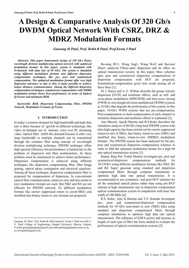
1) Carrier suppressed return to zero(CSRZ)Fig. 1(a) shows the schematic diagram for the generation
of the CSRZ modulation format. In this ,the NRZ signal isgiven to MZM and then given to the phase modulator. Thephase modulator is driven by a sine wave generator at thefrequency half of the bit rate and phase shift of pi betweenany two adjacent bits is introduced. Because of this, thecentral peak at the carrier frequency is suppressed. Itperforms better in the presence of the combined effect of selfphase modulation and chromatic dispersion. Fig. 1(b) showsthe optical spectrum of CSRZ format.
(a)
(b)
Fig 1: (a) schematic of CSRZ modulation format. (b) opticalspectrum of CSRZ format.
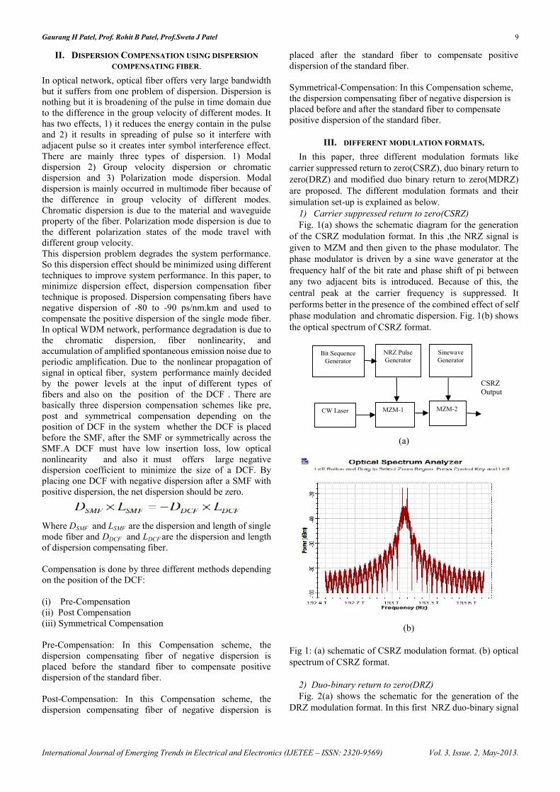
2) Duo-binary return to zero(DRZ)Fig. 2(a) shows the schematic for the generation of the
DRZ modulation format. In this first NRZ duo-binary signal
CSRZOutput
Bit SequenceGenerator
SinewaveGenerator
NRZ PulseGenerator
CW Laser MZM-1 MZM-2
Gaurang H Patel, Prof. Rohit B Patel, Prof.Sweta J Patel 10
International Journal of Emerging Trends in Electrical and Electronics (IJETEE – ISSN: 2320-9569) Vol. 3, Issue. 2, May-2013.
is generated by making the use of a duo-binary pre-coder,NRZ generator and a duo-binary pulse generator. Thegenerator drives the first MZM and then connected with thesecond MZM. The second MZM is driven by a sine wavegenerator with the frequency of 40 GHz and phase of -90.DRZ has bandwidth half of the NRZ format. Fig. 2(b) showsthe optical spectrum of DRZ format.
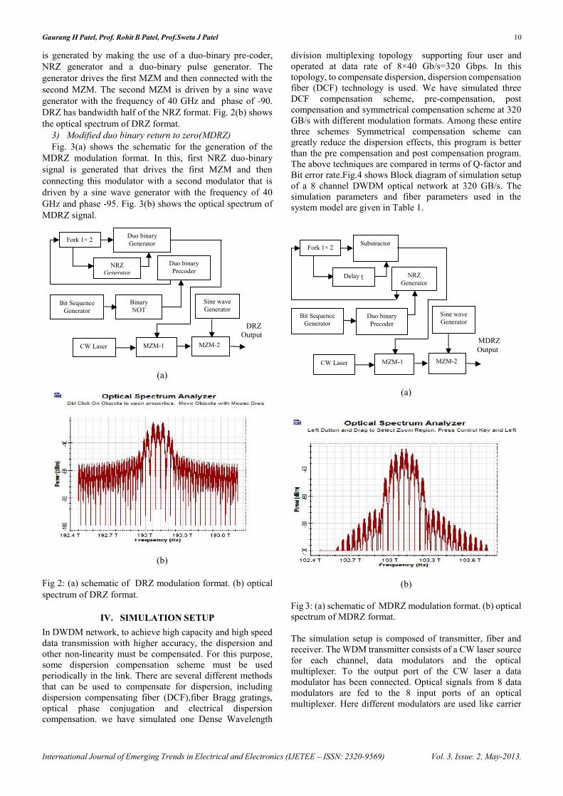
3) Modified duo binary return to zero(MDRZ)Fig. 3(a) shows the schematic for the generation of the
MDRZ modulation format. In this, first NRZ duo-binarysignal is generated that drives the first MZM and thenconnecting this modulator with a second modulator that isdriven by a sine wave generator with the frequency of 40GHz and phase -95. Fig. 3(b) shows the optical spectrum ofMDRZ signal.
(a)
(b)
Fig 2: (a) schematic of DRZ modulation format. (b) opticalspectrum of DRZ format.
IV. SIMULATION SETUPIn DWDM network, to achieve high capacity and high speeddata transmission with higher accuracy, the dispersion andother non-linearity must be compensated. For this purpose,some dispersion compensation scheme must be usedperiodically in the link. There are several different methodsthat can be used to compensate for dispersion, includingdispersion compensating fiber (DCF),fiber Bragg gratings,optical phase conjugation and electrical dispersioncompensation. we have simulated one Dense Wavelength
division multiplexing topology supporting four user andoperated at data rate of 8×40 Gb/s=320 Gbps. In thistopology, to compensate dispersion, dispersion compensationfiber (DCF) technology is used. We have simulated threeDCF compensation scheme, pre-compensation, postcompensation and symmetrical compensation scheme at 320GB/s with different modulation formats. Among these entirethree schemes Symmetrical compensation scheme cangreatly reduce the dispersion effects, this program is betterthan the pre compensation and post compensation program.The above techniques are compared in terms of Q-factor andBit error rate.Fig.4 shows Block diagram of simulation setupof a 8 channel DWDM optical network at 320 GB/s. Thesimulation parameters and fiber parameters used in thesystem model are given in Table 1.
(a)
(b)
Fig 3: (a) schematic of MDRZ modulation format. (b) opticalspectrum of MDRZ format.
The simulation setup is composed of transmitter, fiber andreceiver. The WDM transmitter consists of a CW laser sourcefor each channel, data modulators and the opticalmultiplexer. To the output port of the CW laser a datamodulator has been connected. Optical signals from 8 datamodulators are fed to the 8 input ports of an opticalmultiplexer. Here different modulators are used like carrier
MDRZOutput
Bit SequenceGenerator
Sine waveGenerator
CW Laser MZM-1 MZM-2
NRZGenerator
Fork 1× 2 Substractor
Duo binaryPrecoder
Delay ɽ
DRZOutput
Bit SequenceGenerator
Sine waveGenerator
BinaryNOT
CW Laser MZM-1 MZM-2
NRZGenerator
Fork 1× 2 Duo binaryGenerator
Duo binaryPrecoder
Gaurang H Patel, Prof. Rohit B Patel, Prof.Sweta J Patel 11
International Journal of Emerging Trends in Electrical and Electronics (IJETEE – ISSN: 2320-9569) Vol. 3, Issue. 2, May-2013.
suppressed return to zero, duo binary return to zero andmodified duo binary return to zero.
(a)
(b)
(c)
Fig 4: Block Diagram of Simulation Setup: (a) Precompensation scheme (b) Post compensation scheme (c)Symmetrical compensation scheme.
The transmission channel at 320 GB/s is designed by usingthe fiber parameters of DCF and SMF in such a way that thedispersion is compensated exactly. The gain of the erbiumdoped fiber amplifier (EDFA) placed after each fiber is suchthat it compensates the losses of the preceding fiber. Thenoise figure of the amplifiers is constant and set to 4 dB. Thesignal is then launched over 10 spans of standard single modefiber (SMF) of 50 km each. DWDM system has beensimulated for three different dispersion compensationschemes i.e. pre-compensation, post-compensation andsymmetrical-compensation. In pre-compensation scheme, asshown in Fig 4(a), to compensate the dispersion, DCF fiber of10 km is used before the SMF fiber of 50km length. Also, twoin-line-EDFA with gain of 5 and 10 dB have been used in thelink. The post-compensation scheme has been shown in Fig4(b) where DCF fiber of 10km is used after the SMF fiber of50km length to compensate the dispersion. In symmetricalcompensation scheme, as shown in Fig 4(c), two DCF fibersof 5 km are used before and after of the two SMF fibers of 25km length each. Here four in-line-EDFA have been used inthe link. In the receiver the signal is demultiplexed, detectedby PIN detector, passed through the filter. The filteredelectrical signal is given to the 3R Regenerator. 3R
Regenerator output is connected directly to the BER analyserwhich is used as a visualize to generate graphs and resultssuch as eye diagram, BER, Q value, eye opening etc. Theparameters used in simulation are given in Table I.
Table I. Parameters used in simulation
Parameter ValueBit-Rate 320 GbpsLength of SMF 50 KmLength of DCF 10KmNo. of spans 10Dispersion coefficient of SMF 17 ps/nm/kmDispersion coefficient of DCF -85 ps/nm/kmGain of Inline EDFA placedafter DCF
5 db
Gain of Inline EDFA placedafter SMF
10 db
Attenuation factor of SMF 0.2 db/kmAttenuation factor of DCF 0.5 db/km
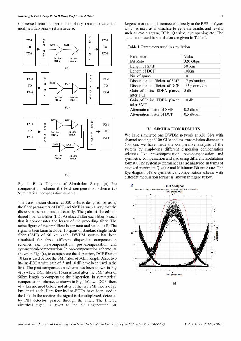
V. SIMULATION RESULTSWe have simulated one DWDM network at 320 Gb/s withchannel spacing of 100 GHz and the transmission distance is500 km. we have made the comparative analysis of thesystem by employing different dispersion compensationschemes like pre-compensation, post-compensation andsymmetric compensation and also using different modulationformats. The system performance is also analysed in terms ofreceived maximum Q value and Minimum Bit error rate. TheEye diagram of the symmetrical compensation scheme withdifferent modulation format is shown in figure below.
(a)
DCFSMF
WDM
MUX
In LineEDFA
In LineEDFA
WDM
DEMUX
TX-1
TO
TX-8
RX-1
TO
RX-8
SMFDCF
WDM
MUX
In LineEDFA
In LineEDFA
WDM
DEMUX
TX-1
TO
TX-8
RX-1
TO
RX-8
In LineEDFA
In LineEDFA
DCFSMF
In LineEDFA
In LineEDFA
DCF SMFWDM
MUX
TX-1
TO
TX-8
RX-1
TO
RX-8
WDM
DEMUX
Gaurang H Patel, Prof. Rohit B Patel, Prof.Sweta J Patel 12
International Journal of Emerging Trends in Electrical and Electronics (IJETEE – ISSN: 2320-9569) Vol. 3, Issue. 2, May-2013.
(b)
(c)
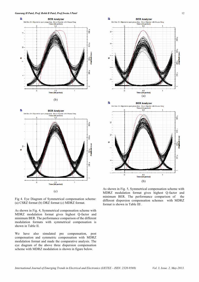
Fig 4. Eye Diagram of Symmetrical compensation scheme:(a) CSRZ format (b) DRZ format (c) MDRZ format.
As shown in Fig. 4, Symmetrical compensation scheme withMDRZ modulation format gives highest Q-factor andminimum BER. The performance comparison of the differentmodulation formats with symmetrical compensation isshown in Table II.
We have also simulated pre compensation, postcompensation and symmetric compensation with MDRZmodulation format and made the comparative analysis. Theeye diagram of the above three dispersion compensationscheme with MDRZ modulation is shown in figure below.
(a)
(b)
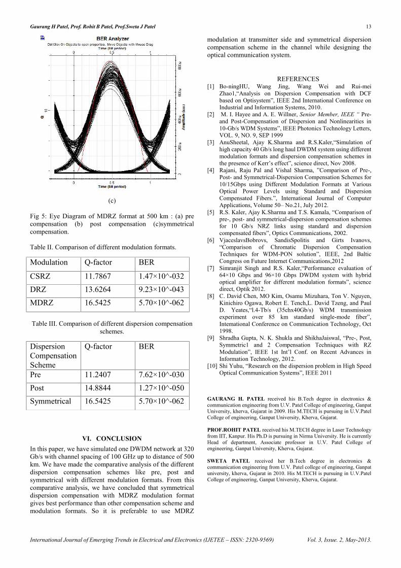
As shown in Fig. 5, Symmetrical compensation scheme withMDRZ modulation format gives highest Q-factor andminimum BER. The performance comparison of thedifferent dispersion compensation schemes with MDRZformat is shown in Table III .
Gaurang H Patel, Prof. Rohit B Patel, Prof.Sweta J Patel 13
International Journal of Emerging Trends in Electrical and Electronics (IJETEE – ISSN: 2320-9569) Vol. 3, Issue. 2, May-2013.
(c)
Fig 5: Eye Diagram of MDRZ format at 500 km : (a) precompensation (b) post compensation (c)symmetricalcompensation.
Table II. Comparison of different modulation formats.
Table III. Comparison of different dispersion compensationschemes.
VI. CONCLUSIONIn this paper, we have simulated one DWDM network at 320Gb/s with channel spacing of 100 GHz up to distance of 500km. We have made the comparative analysis of the differentdispersion compensation schemes like pre, post andsymmetrical with different modulation formats. From thiscomparative analysis, we have concluded that symmetricaldispersion compensation with MDRZ modulation formatgives best performance than other compensation scheme andmodulation formats. So it is preferable to use MDRZ
modulation at transmitter side and symmetrical dispersioncompensation scheme in the channel while designing theoptical communication system.
REFERENCES[1] Bo-ningHU, Wang Jing, Wang Wei and Rui-mei
Zhao1,“Analysis on Dispersion Compensation with DCFbased on Optisystem”, IEEE 2nd International Conference onIndustrial and Information Systems, 2010.
[2] M. I. Hayee and A. E. Willner, Senior Member, IEEE “ Pre-and Post-Compensation of Dispersion and Nonlinearities in10-Gb/s WDM Systems”, IEEE Photonics Technology Letters,VOL. 9, NO. 9, SEP 1999
[3] AnuSheetal, Ajay K.Sharma and R.S.Kaler,“Simulation ofhigh capacity 40 Gb/s long haul DWDM system using differentmodulation formats and dispersion compensation schemes inthe presence of Kerr’s effect”, science direct, Nov 2008.
[4] Rajani, Raju Pal and Vishal Sharma, ”Comparison of Pre-,Post- and Symmetrical-Dispersion Compensation Schemes for10/15Gbps using Different Modulation Formats at VariousOptical Power Levels using Standard and DispersionCompensated Fibers.”, International Journal of ComputerApplications, Volume 50– No.21, July 2012.
[5] R.S. Kaler, Ajay K.Sharma and T.S. Kamala, “Comparison ofpre-, post- and symmetrical-dispersion compensation schemesfor 10 Gb/s NRZ links using standard and dispersioncompensated fibers”, Optics Communications, 2002.
[6] VjaceslavsBobrovs, SandisSpolitis and Girts Ivanovs,“Comparison of Chromatic Dispersion CompensationTechniques for WDM-PON solution”, IEEE, 2nd BalticCongress on Future Internet Communications,2012
[7] Simranjit Singh and R.S. Kaler,“Performance evaluation of64×10 Gbps and 96×10 Gbps DWDM system with hybridoptical amplifier for different modulation formats”, sciencedirect, Optik 2012.
[8] C. David Chen, MO Kim, Osamu Mizuhara, Ton V. Nguyen,Kinichiro Ogawa, Robert E. Tench,L. David Tzeng, and PaulD. Yeates,“l.4-Tb/s (35chx40Gb/s) WDM transmissionexperiment over 85 km standard single-mode fiber”,Intemational Conference on Communication Technology, Oct1998.
[9] Shradha Gupta, N. K. Shukla and ShikhaJaiswal, “Pre-, Post,Symmetric1 and 2 Compensation Techniques with RZModulation”, IEEE 1st Int’l Conf. on Recent Advances inInformation Technology, 2012.
[10] Shi Yuhu, “Research on the dispersion problem in High SpeedOptical Communication Systems”, IEEE 2011
GAURANG H. PATEL received his B.Tech degree in electronics &communication engineering from U.V. Patel College of engineering, GanpatUniversity, kherva, Gujarat in 2009. His M.TECH is pursuing in U.V.PatelCollege of engineering, Ganpat University, Kherva, Gujarat.
PROF.ROHIT PATEL received his M.TECH degree in Laser Technologyfrom IIT, Kanpur. His Ph.D is pursuing in Nirma University. He is currentlyHead of department, Associate professor in U.V. Patel College ofengineering, Ganpat University, Kherva, Gujarat.
SWETA PATEL received her B.Tech degree in electronics &communication engineering from U.V. Patel college of engineering, Ganpatuniversity, kherva, Gujarat in 2010. His M.TECH is pursuing in U.V.PatelCollege of engineering, Ganpat University, Kherva, Gujarat.
Modulation Q-factor BER
CSRZ 11.7867 1.47×10^-032DRZ 13.6264 9.23×10^-043MDRZ 16.5425 5.70×10^-062
DispersionCompensationScheme
Q-factor BER
Pre 11.2407 7.62×10^-030Post 14.8844 1.27×10^-050Symmetrical 16.5425 5.70×10^-062