Embed Size (px)
Citation preview
1
SDI-C-2011 Standard for Composite Steel Floor Deck-Slabs 1 30 November 2011 2
3
1. General 4
5
1.1 Scope: 6
A. This Standard for Composite Steel Floor Deck-Slabs, hereafter referred to as the 7
Standard, shall govern the materials, design, and erection of composite concrete slabs 8
utilizing cold formed steel deck functioning as a permanent form and as reinforcement 9
for positive moment in floor and roof applications in buildings and similar structures. 10
B. The Appendices shall be part of the Standard. 11
C. The User Notes, User Note Attachments, and Commentary shall not be part of the 12
Standard. 13
14
User Note: User Notes, User Note Attachments, and Commentary are intended to 15
provide practical guidance in the use and application of this Standard. 16
17
D. Where the Standard refers to “designer,” this shall mean the entity that is responsible to 18
the Owner for the overall structural design of the project, including the steel deck. 19
20
User Note: This is usually the Structural Engineer of Record. 21
22
E. Equations that appear in this Standard are compatible with the inch-pounds system of 23
units. However, any consistent system of units shall be permitted to be used. SI units 24
or equations shown in parentheses in this standard are for information only, and are not 25
part of this Standard. 26
F. Terms not defined in this Standard, AISI S100 or AISI/AISC shall have the ordinary 27
accepted meaning for the context for which they are intended. 28
G. It shall be permitted to specify deck base metal thickness either by dimensional 29
thickness, or by gage when the relationship of base metal thickness to gage has been 30
defined by the deck manufacturer. However, for the purpose of design, the 31
dimensional thickness shall be used. 32
33
User Note: Both AISI and SDI now specify steel thickness in terms of design 34
thickness in lieu of gage thickness. Gage thicknesses, however, are still commonly 35
referred to in the metal deck industry. Table UN-1.1 shows common gages and 36
corresponding uncoated design and minimum steel thicknesses. 37
38
Table UN-1.1 39
Gage No. Design Thickness Minimum Thickness1
in. mm. in. mm.
22 0.0295 0.75 0.028 0.71
20 0.0358 0.91 0.034 0.86
18 0.0474 1.20 0.045 1.14
16 0.0598 1.52 0.057 1.44
1 Minimum thickness is 95% of the design thickness 40 41
42
1.2 Reference Codes, Standards, and Documents: 43
44
2
A. Codes and Standards: The following documents or portions thereof are referenced in 45
this standard and shall be considered part of the requirements of this Standard. Where 46
these documents conflict with this standard, the requirements of this Standard shall 47
control: 48
: 49
1. American Concrete Institute (ACI) 50
a. ACI 318-11, Building Code Requirements for Structural Concrete 51
2. American Iron and Steel Institute (AISI) 52
a. AISI S100-07 w/S2-10, North American Specification for the Design of 53
Cold-Formed Steel Structural Members, Including Supplement 2 54
(February 2010) 55
b. AISI S905-08, Test Methods for Mechanically Fastened Cold-Formed 56
Steel Connections 57
c. AISI S907-08, Test Standard for Cantilever Test Method for Cold-58
Formed Steel Diaphragms 59
d. AISI/AISC, Standard Definitions for Use in the Design of Steel 60
Structures, 2007 edition 61
3. American Institute of Steel Construction (AISC) 62
a. ANSI/AISC 360-10, Specification for Structural Steel Buildings 63
4. American Society for Testing and Materials (ASTM) 64
a. ASTM A615 / A615M - 09b Standard Specification for Deformed and 65
Plain Carbon-Steel Bars for Concrete Reinforcement 66
b. ASTM A653 / A653M - 10 Standard Specification for Steel Sheet, 67
Zinc-Coated (Galvanized) or Zinc-Iron Alloy-Coated (Galvannealed) by 68
the Hot-Dip Process 69
c. ASTM A706 / A706M - 09b Standard Specification for Low-Alloy 70
Steel Deformed and Plain Bars for Concrete Reinforcement 71
d. ASTM A820 / A820M – 06, Standard Specification for Steel Fibers for 72
Fiber-Reinforced Concrete 73
e. ASTM A1008 / A1008M - 10, Standard Specification for Steel, Sheet, 74
Cold-Rolled, Carbon, Structural, High-Strength Low-Alloy, High-75
Strength Low-Alloy with Improved Formability, Solution Hardened, 76
and Bake Hardenable 77
f. ASTM A1064 / A1064M - 10 Standard Specification for Steel Wire and 78
Welded Wire Reinforcement, Plain and Deformed, for Concrete 79
g. ASTM C1116 / C1116M - 10 Standard Specification for Fiber-80
Reinforced Concrete 81
h. ASTM D7508 / D7508M - 10 Standard Specification for Polyolefin 82
Chopped Strands for Use in Concrete 83
5. American Society of Civil Engineers (ASCE) 84
a. SEI/ASCE 7-10, Minimum Design Loads for Buildings and Other 85
Structures 86
6. American Welding Society (AWS) 87
a. AWS D1.1:2010, Structural Welding Code-Steel 88
b. AWS D1.3:2008, Structural Welding Code-Sheet Steel 89
7. Steel Deck Institute (SDI) 90
a. SDI-T-CD-2011, Test Standard for Composite Steel Deck-Slabs 91
92
3
B. Reference Documents: The following documents or portions thereof are referenced in 93
this standard and shall be considered part of the requirements of this Standard. Where 94
these documents conflict with this standard, requirements of this Standard shall govern: 95
1. Steel Deck Institute (SDI) 96
a. SDI-DDM, Diaphragm Design Manual, 3rd
Edition, including 97
Appendices I through VI 98
99
User Note: The following documents are referenced within the user notes: 100
1. American Association of State Highway and Transportation Officials 101
(AASHTO) 102
a. AASHTO LRFD Bridge Design Specifications, Customary U.S. Units, 103
5th Edition, with 2010 Interim Revisions 104
2. American Concrete Institute (ACI) 105
a. ACI 215R-92, Considerations for Design of Concrete Structures 106
Subjected to Fatigue Loading 107
b. ACI 302.1R-04, Guide for Concrete Floor and Slab Construction 108
c. ACI 224.1R-07, Causes, Evaluation, and Repair of Cracks in Concrete 109
Structures 110
d. ACI 318-11, Building Code Requirements for Structural Concrete 111
e. ACI 544 3R-08, Guide for the Specification, Proportioning and 112
Production of Fiber Reinforced Concrete 113
f. ACI Concrete Terminology, http://terminology.concrete.org 114
3. American Institute of Steel Construction (AISC) 115
a. AISC Design Guide No. 11, Floor Vibrations Due to Human Activity, 116
1997 117
4. American Iron and Steel Institute (AISI) 118
a. AISI S100-07 w/S2-10, North American Specification for the Design of 119
Cold-Formed Steel Structural Members, Including Supplement 2 120
(February 2010) 121
b. AISI S907-08, Test Standard for Cantilever Test Method for Cold-122
Formed Steel Diaphragms 123
5. American Society for Testing and Materials (ASTM) 124
a. ASTM A653 / A653M - 10 Standard Specification for Steel Sheet, 125
Zinc-Coated (Galvanized) or Zinc-Iron Alloy-Coated (Galvannealed) by 126
the Hot-Dip Process 127
b. ASTM A1008 / A1008M - 10, Standard Specification for Steel, Sheet, 128
Cold-Rolled, Carbon, Structural, High-Strength Low-Alloy, High-129
Strength Low-Alloy with Improved Formability, Solution Hardened, 130
and Bake Hardenable 131
c. ASTM E119 - 10b,, Standard Test Methods for Fire Tests of Building 132
Construction and Materials 133
6. Concrete Reinforcing Steel Institute (CRSI) 134
a. CRSI Manual of Standard Practice, 28th
Edition, 2009 135
7. Steel Deck Institute (SDI) 136
a. SDI-CDD, Composite Deck Design Handbook, 2nd
Edition 137
b. SDI-DDM, Diaphragm Design Manual, 3rd
Edition, including 138
Appendices I through VI 139
c. SDI-MDCQ, Metal Deck and Concrete Quantities (SDI White Paper) 140
d. SDI-MOC, Manual of Construction with Steel Deck, 2nd
Edition 141
4
e. SDI Position Statement “Use of Composite Steel Floor Deck in Parking 142
Garages.” 143
8. Underwriters Laboratories (UL) 144
a. Fire Resistance Directory 145
9. Wire Reinforcing Institute (WRI) 146
a. WWR-500-R-10, Manual of Standard Practice-Structural Welded Wire 147
Reinforcement 148
149
1.3 Construction Documents: The construction documents shall describe the composite slabs that 150
are to be constructed and shall include not less than the following information: 151
A. Loads 152
1. Composite slab loads as required by the applicable building code. Where 153
applicable, load information shall include concentrated loads. 154
2. Assumed construction phase loads. 155
B. Structural framing plans for all composite slabs showing the size, location and type of 156
all deck supports. 157
C. Deck and Deck Attachment 158
1. Depth, type (profile), and design thickness. 159
2. Deck material (including yield strength) and deck finish, 160
3. Deck attachment type, spacing, and details. 161
D. Concrete and Reinforcing 162
1. Specified concrete strength, f’c 163
2. Specified concrete density (and tolerance if required for fire rating assembly) 164
3. Specified strength or grade of reinforcing steel or welded wire reinforcement (if 165
used) 166
4. Size, extent and location of all reinforcement (if used) 167
5. Slab thicknesses 168
6. Discontinuous fiber reinforcement material, type and dosage (if used). 169
170
User Note: The following is an example of a composite slab as it could be specified 171
on the contract drawings: “Composite slab shall consist of 2 inch deep G-60 172
galvanized composite steel deck, design thickness 0.0358 inch (20 gage), (Type XX by 173
XX, Inc or approved equivalent) with 3 inch thick, 3000 psi, normal-weight concrete 174
topping (total thickness = 5 inches) reinforced with XXX.” 175
176
2. Products 177
178
2.1 Material: 179
180
A. All sheet steel used for deck or accessories shall have a minimum specified yield stress 181
that meets or exceeds 33 ksi (230 Mpa). 182
1 For the case where the steel deck acts as a form, design yield and tensile 183
stresses shall be determined in accordance with AISI S100, Section A2. 184
2. For the case where the steel deck acts as tensile reinforcement for the composite 185
deck-slab, the steel shall conform to AISI S100, Section A2. When the ductility 186
of the steel measured over a two-inch (50 mm) gage length is 10% or greater, 187
the maximum design yield stress shall not exceed the lesser of 50 ksi or Fy. 188
When the ductility of the steel measured over a two-inch (50 mm) gage length 189
is less than 10%, the maximum design yield stress shall not exceed the lesser of 190
50 ksi (345 Mpa) or 0.75 Fy. 191
5
3. When the ductility of the steel used for deck, measured over a two-inch (50 192
mm) gage length, is less than 10%, the ability of the steel to be formed without 193
cracking or splitting shall be demonstrated. 194
195
B. Sheet steel for deck shall conform to AISI S100, Section A2. 196
197
Commentary: Most steel deck is manufactured from steel conforming to ASTM 198
A1008 /A1008M, Structural Sheet for uncoated or uncoated top/painted bottom deck or 199
from ASTM A653 / A653M, Structural Sheet for galvanized deck. In most cases the 200
designer will choose one finish or the other. However, both types of finish may be 201
used on a project, in which case the designer must indicate on the plans and project 202
specifications the areas in which each is used. (Refer to Section 2.3 of this standard). 203
Stainless steel is not recommended due to the lack of available performance data. 204
205
C. Sheet steel for accessories that carry defined loads shall conform to AISI S100, Section 206
A2. Sheet steel for non-structural accessories that do not carry defined loads shall be 207
permitted to be any steel that is adequate for the proposed application. 208
D. Concrete and Reinforcement: 209
1. Concrete placed on steel deck shall conform to ACI 318, Chapters 3, 4 and 5, 210
except as modified by Sections 2.1.D.2 and 2.1.D.3. 211
2. The specified concrete compressive strength shall not be less than 3000 psi (21 212
MPa). The maximum compressive strength used to calculate the strength of the 213
composite deck-slab shall not exceed 6000 psi (42 MPa). 214
215
User Note: Load tables and labeled fire resistant rated assemblies may require concrete 216
compressive strengths in excess of 3000 psi. The average compressive strength of the 217
concrete may exceed 6000 psi, but a maximum strength of 6000 psi is to be used in 218
calculating the strength of the composite deck-slab. 219
220
3. Admixtures containing chloride salts or other substances that are corrosive or 221
otherwise deleterious to the steel deck and embedded items shall not be 222
permitted. 223
4. Steel Reinforcing shall conform to the following: 224
a. Deformed reinforcing bars: ASTM A615 or ASTM A706. 225
b. Welded wire reinforcement: ASTM A1064. 226
c. Other deformed reinforcing bars or welded wire reinforcement as 227
permitted by ACI 318, Section 3.5.3. 228
5. Discontinuous fiber reinforcement shall conform to the following: 229
a. Steel fibers: ASTM A820. 230
b. Macrosynthetic fibers: ASTM D7508. 231
232
2.2 Tolerance of Delivered Material: 233
A. The minimum uncoated steel thickness as delivered to the job site shall not at any 234
location be less than 95% of the design thickness, however lesser thicknesses shall be 235
permitted at bends, such as corners, due to cold-forming effects. 236
237
User Note: The minimum delivered thickness is in accordance with AISI S100. 238
239
B. Panel length shall equal the specified panel length, plus or minus ½ inch (13mm). 240
C. Panel cover width shall be no less than 3/8 inch (10 mm) less than the specified panel 241
width, nor more than 3/4 inch (19 mm) greater than the specified width. 242
6
D. Panel camber and/or sweep shall not be greater than 1/4 inch in a 10 foot length (6 mm 243
in 3 m). 244
E. Panel end out of square shall not exceed 1/8 inch per foot of panel width (10 mm per 245
m). 246
247 2.3 Finish: 248
A. Galvanizing shall conform to ASTM A653 / A653M 249
B. A shop coat of primer paint (bottom side only) shall be applied to steel sheet if 250
specified by the designer. 251
C. The finish on the steel deck shall be specified by the designer. 252
253
Commentary: The finish on the steel composite deck must be specified by the 254
designer and be suitable for the environment to which the deck is exposed within the 255
finished structure. Because the composite deck is the positive bending reinforcement 256
for the slab, its service life should at least be equal to the design service live of the 257
structure. Zinc-Aluminum finishes are not recommended. When composite deck with 258
an unpainted top and painted bottom is used, the primer coat is intended to protect the 259
steel for only a short period of exposure in ordinary atmospheric conditions and shall 260
be considered an impermanent and provisional coating. In highly corrosive or chemical 261
atmospheres or where reactive materials could be in contact with the steel deck, special 262
care in specifying the finish should be used, which could include specialized coatings 263
or materials. If specifying painted deck in areas that require spray-on fireproofing, the 264
paint must be permitted by the applicable fire rated assembly. Not all paints are 265
approved for fire rated assemblies. This requirement must be clearly called out in the 266
contract documents. In general, there are three types of fire resistive assemblies; those 267
achieving the fire resistance by membrane protection, direct applied protection, or with 268
an unprotected assembly. Of these three, only the systems that utilize direct applied 269
protection are concerned with the finish of the steel deck. In these systems, the finish 270
of the steel deck can be the factor that governs the fire resistance rating that is 271
achieved. In assemblies with direct applied fire protection the finish (paint) is critical. 272
In the Underwriters Laboratories Fire Resistance Directory, some deck manufacturing 273
companies have steel deck units that are classified in some of the D700, D800, and 274
D900-series concrete and steel floor units. These classified deck units (Classified Steel 275
Floor and Form Units) are shown as having a galvanized finish or a 276
phosphatized/painted finish. These classified deck units have been evaluated for use in 277
these specific designs and found acceptable. 278
279
280
2.4 Design: 281
A. Deck as a form 282
1. Design by either Allowable Strength Design (ASD) or Load and Resistance 283
Factor Design (LRFD) shall be permitted. The section properties and allowable 284
strength (ASD) or design strength (LRFD) for the steel deck shall be computed 285
in accordance with AISI S100. 286
2. Deck shall be evaluated for strength under the following load combinations: 287
a. Allowable Stress Design 288
289
wdc + wdd + wlc (Eq. 2.4.1) 290
291
wdc + wdd + Plc (Eq. 2.4.2) 292
293
7
wdd + wcdl (Eq. 2.4.3) 294
295
Where: 296
wdc = dead weight of concrete 297
wdd = dead weight of the steel deck 298
wlc = uniform construction live load (combined with fluid 299
concrete) not less than 20 psf (0.96 kPa) 300
wcdl = uniform construction live load (combined with bare 301
deck), not less than 50 psf (2.40 kPa) 302
Plc = concentrated construction live load per unit width of 303
pounds on a 1 foot width (2.19 kN on a 1 meter width) 304
305
User Note: The uniform construction live load of 20 psf is considered adequate for 306
typical construction applications that consist of concrete transport and placement by 307
hose and concrete finishing using hand tools. The designer typically has little control 308
over means-and-methods of construction, and should bring to the attention of the 309
constructor that bulk dumping of concrete using buckets, chutes, or handcarts, or the 310
use of heavier motorized finishing equipment such as power screeds, may require 311
design of the deck as a form using uniform construction live loads, wlc ,of 50 psf or 312
greater. Section A1.3.1 requires that the designer include the assumed construction 313
loads in the construction documents and it is suggested that the constructions 314
documents require verification of adequacy by the constructor. 315
316
User Note: The designer should account for additional loads attributable to concrete 317
ponding due to deflections of the structural system, including deck and support 318
framing. See SDI-MDCQ for additional information. 319
320
b. Load and Resistance Factor Design 321
322
1.6wdc + 1.2wdd + 1.4wlc (Eq. 2.4.4) 323
324
1.6wdc + 1.2wdd + 1.4Plc (Eq. 2.4.5) 325
326
1.2wdd + 1.4wcdl (Eq. 2.4.6) 327
328
Commentary: The load factor used for the dead weight of the concrete is 1.6 because 329
of delivering methods and an individual sheet can be subjected to this load. The use of 330
a load factor of 1.4 for construction load in LRFD design is calibrated to provide 331
equivalent design results in ASD design. Refer to the commentary of AISI S100 for 332
additional information. 333
334
3. Cantilever spans shall be evaluated for strength under the following load 335
combinations: 336
a. Allowable Strength Design: Equations 2.4.1 and 2.4.2 shall be applied 337
to both the cantilever span and the adjacent span. The concentrated 338
construction live load (Plc) shall be applied at the end of the cantilever. 339
b. Load and Resistance Factor Design: Equations 2.4.4 and 2.4.5 shall be 340
applied to both the cantilever span and the adjacent span. The 341
concentrated construction live load (Plc) shall be applied at the end of 342
the cantilever. 343
4. Special loading considerations: 344
8
a. The specified construction live loads shall be increased when required 345
by construction operations. 346
b. Loads shall be applied in a sequence that simulates the placement of the 347
concrete, in accordance with Appendix 1. Rational analysis shall be 348
permitted to be used for developing shear and moment diagrams and 349
calculating deflections for non-uniform spans. 350
351
Commentary: The loading shown in Figure 1 of Appendix 1 is representative of the 352
sequential loading of fresh concrete on the deck. The 150 pound per foot of width (2.19 353
kN per 1 m of width) load is the equivalent of distributing a 300 pound (1.33 kN) 354
worker over a 2 foot (600 mm) width. Experience has shown this to be a conservative 355
distribution. 356
357
Single span deck conditions have no redundancy because they are statically 358
determinate, as opposed to multi-span conditions that are statically indeterminate. 359
Because of this lack of redundancy, additional consideration should be given to proper 360
specification of construction live and dead loads. Allowable construction spans for 361
single-span deck may be shorter than for multi-span applications, and the designer 362
must consider this in locations where it is impossible to install the deck in a multi-span 363
condition, such as between stair and elevator towers. Whenever possible, the deck 364
should be designed as a multi-span system that does not require shoring during 365
concrete placement. 366
The specified construction live loads reflect nominal loads from workers and 367
tools and do not include loads of equipment such as laser screeds or power trowels nor 368
additional concrete weight due to ponding. If anticipated construction activities 369
include these additional loads, they should be considered in the design. 370
371 5. Deck Deflection 372
a. Calculated deflections of the deck as a form shall be based on the load 373
of the concrete as determined by the design slab thickness and the self-374
weight of the steel deck, uniformly loaded on all spans, shall be limited 375
to the lesser of 1/180 of the clear span or 3/4 inch (19 mm). Calculated 376
deflections shall be relative to supporting members. 377
b. The deflection of cantilevered deck as a form, as determined by slab 378
thickness and self-weight of the steel deck, shall not exceed a/90, where 379
“a” is the cantilever length, nor 3/4 inches (19 mm). 380
381
Commentary: The deflection calculations do not take into account construction loads 382
because these are considered to be temporary loads. The deck is designed to always be 383
in the elastic range, so removal of temporary loads will allow the deck to recover, 384
unless construction overloads cause the stress in the deck to exceed the elastic limits of 385
the deck. The supporting structural steel also deflects under the loading of the concrete. 386
The designer is urged to check the deflection of the total system. Typical load 387
tables are based on uniform slab thickness. If the designer wants to include additional 388
concrete loading on the deck because of frame deflection, the additional load should be 389
shown on the design drawings or stated in the deck section of the contract documents. 390
391
6. Minimum Bearing and Edge Distance: Minimum bearing lengths and fastener 392
edge distances shall be determined in accordance with AISI S100. 393
394
9
User Note: Figure 2 in Appendix 1 indicates support reactions. The designer should 395
check the deck web crippling capacity based on available bearing length. 396
397
7. Diaphragm Shear Capacity: Diaphragm strength and stiffness shall be 398
determined utilizing the bare steel deck capacity without concrete in accordance 399
with: 400
a. SDI-DDM 401
b. Tests conducted in accordance with AISI S907 402
c. Other methods approved by the building official. 403
404
Commentary: Unless otherwise required by the governing building code, safety 405
factors and resistance factors should be as shown in Table D5 of AISI S100 for bare 406
steel deck diaphragms. When SDI-DDM is the basis of diaphragm design, fasteners 407
and welds that do not have flexibility and strength properties listed in SDI-DDM 408
Section 4 can demonstrate flexibility and strength properties through testing in 409
accordance with AISI S905 or other testing methods. Fastener or weld strength 410
defined in AISI S100 or other methods can be used with the SDI-DDM method. 411
It is always conservative to neglect the contribution of sidelap connections to 412
diaphragm strength and stiffness. Side lap fillet weld and top seam and side seam weld 413
flexibility can be calculated in accordance with SDI-DDM Section 4.4 and sidelap fillet 414
weld and side seam weld strength can be calculated in accordance with AISI S100. 415
416
8. Connections: Deck shall be attached to supports to resist loads and to provide 417
structural stability for the supporting member Connections shall be designed 418
in accordance with AISI S100 or strengths shall be determined by testing in 419
accordance with AISI S905. Tests shall be representative of the design. When 420
tests are used and the design allows either end laps or single thickness 421
conditions, both conditions shall be tested. 422
423
B. Deck and Concrete as a Composite Slab: 424
1. Strength: Strength of the composite deck-slab shall be determined in 425
accordance with one of the following methods 426
a. “Prequalified Section Method” as per Appendix 2. 427
b. “Shear Bond Method” as per Appendix 3. 428
c. Full scale performance testing as per SDI-T-CD. 429
d. Other methods approved by the building official. 430
2. Deck shall be evaluated for strength under the load combinations required by 431
the applicable building code. In the absence of a building code, the load 432
combinations prescribed by ASCE 7 shall be used. 433
3. Load Determination: The superimposed load capacity shall be determined by 434
deducting the weight of the slab and the deck from the total load capacity. 435
Unless composite deck-slabs are designed for continuity, slabs shall be assumed 436
to act on simple spans. 437
438 Commentary: Most published live load tables are based on simple span analysis of 439
the composite system; that is, a continuous slab is assumed to crack over each support 440
and to carry load as a series of simple spans. 441
442
Commentary: By using the reference analysis techniques or test results, the deck 443
manufacturer determines the live loads that can be applied to the composite deck-slab 444
combination. The results are usually published as uniform load tables. For most 445
10
applications, the deck thickness and profile is selected so that shoring is not required; 446
the live load capacity of the composite system is usually more than adequate for the 447
superimposed live loads. In calculating the section properties of the deck, AISI S100 448
may require that compression zones in the deck be reduced to an “effective width,” but 449
as tensile reinforcement, the total area of the cross section may be used. (See 450
Appendix 3) 451
Coatings other than those tested may be investigated, and if there is evidence 452
that their performance is better than that of the tested product, additional testing may 453
not be required. 454
455
4. Concrete: Specified concrete compressive strength (f’c) shall comply with 456
Section 2.1 and shall not be less then 3000 psi (21 MPa), nor less than that 457
required for fire resistance ratings or durability. 458
459 Commentary: Load tables are generally calculated by using a concrete strength of 460
3000 psi (21 MPa). Composite slab capacities are not greatly affected by variations in 461
concrete compressive strength; but if the strength falls below 3000 psi (21 MPa), it 462
would be advisable to check shear anchor design for composite beam action. 463
464
a. Minimum Cover: The concrete thickness above the top of the steel deck 465
shall not be less than 2 inches (50 mm), nor that required by any 466
applicable fire resistance rating requirements. Minimum concrete cover 467
for reinforcement shall be in accordance with ACI 318. 468
5. Deflection: Deflection of the composite slab shall be in accordance with the 469
requirements of the applicable building code. 470
a. Cross section properties shall be calculated in accordance with 471
Appendix 4. 472
b. Additional deflections resulting from concrete creep, where applicable, 473
shall be calculated by multiplying the immediate elastic deflection due 474
to the sustained load by the following factors: 475
i. (1.0) for load duration of 3 months 476
ii. (1.2) for load duration of 6 months 477
iii. (1.4) for load duration of 1 year 478
iv. (2.0) for load duration of 5 years. 479
480
Commentary: Live load deflections are seldom a controlling design factor. A 481
superimposed live load deflection of span/360 is typically considered to be acceptable. 482
The deflection of the slab/deck combination can be predicted by using the average of 483
the cracked and uncracked moments of inertia as determined by the transformed 484
section method of analysis. Refer to Appendix 4 of this standard or SDI-CDD. 485
486
User Note: Limited information on creep deflections is available. This method is 487
similar to the procedure for reinforced concrete slabs. Because the steel deck initially 488
carries the weight of the concrete, only the superimposed loads should be considered 489
when creep deflections are a concern. 490
491
492
User Note: Floor vibration performance is the result of the behavior of entire floor 493
system, including the support framing. The designer should check vibration 494
performance using commonly accepted methods, which may include AISC Design 495
Guide No. 11. 496
11
497
6. Special Loads: The following loads shall be considered in the analysis and 498
calculations for strength and deflection: 499
a. Suspended Loads. 500
b. Concentrated Loads 501
c. Moving Loads 502
d. Cyclic Loads 503
504
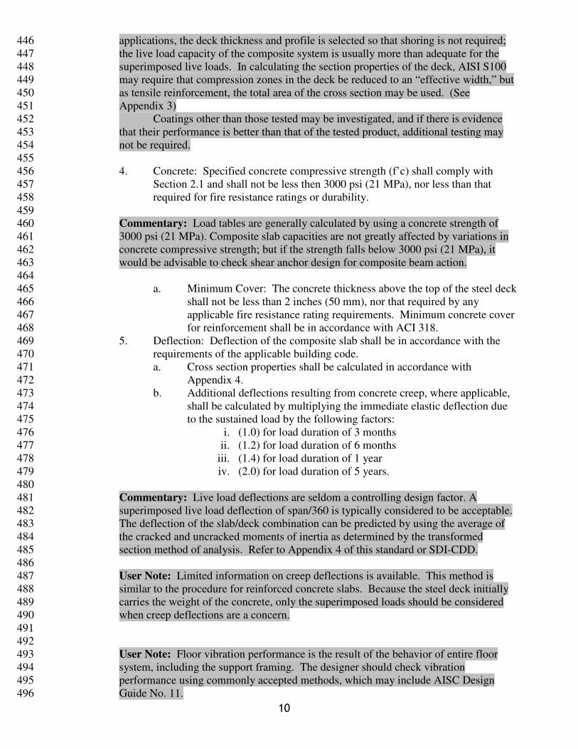
7. One-way Shear Strength: This section shall be used to determine the one-way 505
shear strength of the composite deck-slab. 506
507
ccvDscvn AfVVV '4φφφφ ≤+= (Eq. 2.4.7a) (in-lb) 508
ccvDscvn AfVVV '172.0φφφφ ≤+= (Eq. 2.4.7b) (SI) 509
510
Where: 511
512
ccc AfV'2λ= (Eq. 2.4.8a) (in-lb) 513
ccc AfV'086.0 λ= (Eq. 2.4.8b) (SI) 514
515
VD = shear strength of the steel deck section calculated in accordance 516
with AISI S100, kips (kN) 517
Ac = concrete area available to resist shear, in2 (mm
2), see Figure 2-1. 518
λ = 1.0 where concrete density exceeds 130 lbs/ft3
(2100 kg/m3); 519
0.75 where concrete density is equal to or less than 130 lbs/ft3
520
(2100 kg/m3). 521
φv = 0.75 522
φs = 0.85 523
12
524 525
Figure 2-1 One-Way Shear Parameters 526 527
8. Punching Shear Resistance: The critical surface for calculating punching shear 528
shall be perpendicular to the plane of the slab and located outside of the 529
periphery of the concentrated load or reaction area. The factored punching 530
shear resistance, Vpr, shall be determined as follows: 531
532
( ) cocvcocvcpr hbfhbfV '4'42 φφβ ≤+= (Eq. 2.4.9a) (in-lb) 533
( ) cocvcocvcpr hbfhbfV '172.0'42043.0 φφβ ≤+= (Eq. 2.4.9b) (SI) 534
535
Where: 536
bo = perimeter of critical section, in. (mm) 537
hc = thickness of concrete cover above steel deck, in. (mm) 538
βc = ratio of long side to short side of concentrated load or reaction 539
area 540
φv = 0.75 541
542
9. Concentrated Loads: Concentrated loads shall be permitted to be laterally 543
distributed perpendicular to the deck ribs in accordance with this section. 544
13
Alternate lateral load distributions based on rational analysis shall be permitted 545
when allowed by the building official. 546
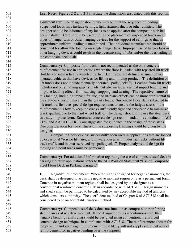
a. Concentrated loads shall be distributed laterally (perpendicular to the 547
ribs of the deck) over an effective width, be. The load distribution over 548
the effective width, be, shall be uniform. 549
b. The concrete above the top of steel deck shall be designed as a 550
reinforced concrete slab in accordance with ACI 318, transverse to the 551
deck ribs, to resist the weak axis moment, Mwa, over a width of slab 552
equal to W. Appropriate load factors as required by ACI 318 shall be 553
applied to the weak axis moment. 554
555
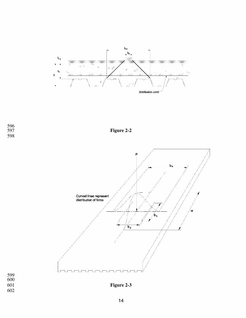
bm = b2 + 2 tc + 2 tt (Eq. 2.4.10) 556
557
be = bm + (2)(1-x/L)x ≤ 106.8 (tc/h) for single 558
span bending (Eq. 2.4.11) 559
560
be = bm + (4/3)(1-x/L)x ≤ 106.8 (tc/h) for 561
continuous span bending when reinforcing steel is provided in the 562
concrete to develop negative bending. (Eq. 2.4.12) 563
564
be = bm + (1-x/L)x ≤ 106.8 (tc/h) for shear 565
(Eq. 2.4.13) 566
567
W = L/2 + b3 ≤ L (Eq. 2.4.14) 568
569
Mwa = 12 P be / (15W) in-lb per foot [ P be / (15 W) N-570
mm per mm ] (Eq. 2.4.15) 571
572
Where: 573
574
be = Effective width of concentrated load, perpendicular to 575
the deck ribs, in (mm) 576
bm = Projected width of concentrated load, perpendicular to 577
the deck ribs, measured at top of steel deck, in (mm) 578
b2 = Width of bearing perpendicular to the deck ribs, in (mm) 579
b3 = Length of bearing parallel to the deck ribs, in (mm) 580
h = Depth of composite deck-slab, measured from bottom of 581
steel deck to top of concrete slab, in (mm) 582
L = Deck span length, measured from centers of supports, in 583
(mm) 584
Mwa = Weak axis bending moment, perpendicular to deck ribs, 585
of width, in.-lbs, (N-mm per mm of width) 586
P = Magnitude of concentrated load, lbs (N) 587
tc = Thickness of concrete above top of steel deck, in (mm) 588
tt = Thickness of rigid topping above structural concrete (if 589
any), in (mm) 590
W = Effective length of concentrated load, parallel to the deck 591
ribs, in (mm) 592
x = Distance from center of concentrated load to nearest 593
support, in (mm) 594
595
14
596 Figure 2-2 597
598
599 600
Figure 2-3 601 602
15
User Note: Figures 2-2 and 2-3 illustrate the dimensions associated with this section. 603
604
Commentary: The designer should take into account the sequence of loading. 605
Suspended loads may include ceilings, light fixtures, ducts or other utilities. The 606
designer should be informed of any loads to be applied after the composite slab has 607
been installed. Care should be used during the placement of suspended loads on all 608
types of hanger tabs or other hanging devices for the support of ceilings so that an 609
approximate uniform loading is maintained. The individual manufacturer should be 610
consulted for allowable loading on single hanger tabs. Improper use of hanger tabs or 611
other hanging devices could result in the overstressing of tabs and/or the overloading of 612
the composite deck-slab. 613
614 Commentary: Composite floor deck is not recommended as the only concrete 615
reinforcement for use in applications where the floor is loaded with repeated lift truck 616
(forklift) or similar heavy wheeled traffic. (Lift trucks are defined as small power 617
operated vehicles that have devices for lifting and moving product. The definition of 618
lift trucks does not include manually operated “pallet jacks.”) Loading from lift trucks 619
includes not only moving gravity loads, but also includes vertical impact loading and 620
in-plane loading effects from starting, stopping, and turning. The repetitive nature of 621
this loading, including impact, fatigue, and in-plane effects can be more detrimental to 622
the slab-deck performance than the gravity loads. Suspended floor slabs subjected to 623
lift truck traffic have special design requirements to ensure the fatigue stress in the 624
reinforcement is low to keep the cracks sufficiently tight and serviceable to minimize 625
crack spalling due to the hard wheel traffic. The design should only use the steel deck 626
as a stay-in-place form. Structural concrete design recommendations contained in ACI 627
215R and AASHTO-LRFD are suggested for guidance in the design of these slabs. 628
Due consideration for the stiffness of the supporting framing should be given by the 629
designer. 630
Composite floor deck has successfully been used in applications that are loaded 631
by occasional “scissor lift” use, and in warehouses with industrial racks without lift 632
truck traffic and in areas serviced by “pallet jacks.” Proper analysis and design for 633
moving and point loads must be performed. 634
635
Commentary: For additional information regarding the use of composite steel deck in 636
parking structure applications, refer to the SDI Position Statement “Use of Composite 637
Steel Floor Deck in Parking Garages.” 638
639
10. Negative Reinforcement: When the slab is designed for negative moments, the 640
deck shall be designed to act in the negative moment region only as a permanent form. 641
Concrete in negative moment regions shall be designed by the designer as a 642
conventional reinforced concrete slab in accordance with ACI 318. Design moments 643
and shears shall be permitted to be calculated by any acceptable method of analysis 644
which considers continuity. The coefficient method of Chapter 8 of ACI 318 shall be 645
considered to be an acceptable analysis method. 646
647
Commentary: Composite steel deck does not function as compression reinforcing 648
steel in areas of negative moment. If the designer desires a continuous slab, then 649
negative bending reinforcing should be designed using conventional reinforced 650
concrete design techniques in compliance with ACI 318. The reinforcement chosen for 651
temperature and shrinkage reinforcement most likely will not supply sufficient area of 652
reinforcement for negative bending over the supports. 653
16
654
11. Cantilevered Slabs: At cantilevered slabs, the deck shall be considered to act 655
only as a permanent form. The slab shall be designed by the designer for 656
negative bending in accordance with ACI 318. 657
658
Commentary: At cantilevered slabs, the deck acts only as a permanent form. 659
Composite steel deck does not function as compression reinforcing steel at cantilevers. 660
Negative bending reinforcing at the cantilever should be designed using conventional 661
reinforced concrete design techniques in compliance with ACI 318. The reinforcement 662
chosen for temperature and shrinkage reinforcing most likely will not supply sufficient 663
area of reinforcement for negative bending at the cantilever. 664
665
12. Diaphragm Shear Capacity: Diaphragm strength and stiffness shall be 666
determined in accordance with: 667
a. SDI-DDM 668
b. Tests conducted in accordance with AISI S907 669
c. Other methods approved by the building official. 670
671
Commentary: Unless otherwise required by the governing building code, when using 672
the SDI-DDM method, the safety and resistance factors found in the SDI-DDM should 673
be used, When SDI-DDM is the basis of diaphragm design, fasteners and welds that do 674
not have flexibility and strength properties listed in SDI-DDM Section 4 can 675
demonstrate flexibility and strength properties through testing in accordance with AISI 676
S905 or other testing methods. Fastener or weld strength defined in AISI S100 or other 677
methods can be used with the SDI-DDM method. It is always conservative to neglect 678
the contribution of sidelap connections to diaphragm strength and stiffness. Side lap 679
fillet weld and top seam and side seam weld flexibility can be calculated in accordance 680
with SDI-DDM Section 4.4 and sidelap fillet weld and side seam weld strength can be 681
calculated in accordance with AISI S100. 682
When strength is based on test, the safety and resistance factors should be determined 683
in accordance with AISI S100 Chapter F, but should shall not be less critical than those 684
for concrete diaphragms contained in ACI 318, Section 9.3. The following statistical 685
data may be used with AISI S100 for calculating the resistance factor: 686
βo = 3.50 687
Mm = 1.10 688
Vm = 0.10 689
Fm = 0.90 690
Vf = 0.10 691
Pm = 1.00 692
This statistical data is based on a connection limit state, and is differs from the data in 693
the SDI T-CD standard for gravity loads. When using this data, the factor if safety 694
should be calculated in accordance with AISI S100, Section F. 695
696
User Note: In instances where the required diaphragm capacity exceeds what can be 697
calculated using SDI-DDM, a designer can potentially develop additional capacity by 698
designing the diaphragm as a reinforced concrete diaphragm in accordance with ACI 699
318. This design option as a concrete diaphragm is outside the scope of this standard. 700
701
13. Reinforcement for Temperature and Shrinkage: 702
17
a. Reinforcement for crack control purposes other than to resist stresses 703
from quantifiable structural loadings shall be permitted to be provided 704
by one of the following methods: 705
1. Welded wire reinforcement or reinforcing bars with a minimum 706
area of 0.00075 times the area of the concrete above the deck 707
(per foot or meter of width), but not be less than the area 708
provided by 6 x 6 – W1.4 x W1.4 (152 x 152 – MW9 x MW9) 709
welded wire reinforcement. 710
2. Concrete specified in accordance with ASTM C1116, Type I, 711
containing steel fibers meeting the criteria of ASTM A820, Type 712
I , Type II, or Type V, at a dosage rate determined by the fiber 713
manufacturer for the application, but not less than 25 lb/cu yd 714
(14.8 kg/cu meter). 715
3. Concrete specified in accordance with ASTM C1116, Type III, 716
containing macrosynthetic fibers meeting the criteria of ASTM 717
D7508 at a dosage rate determined by the fiber manufacturer for 718
the application, but not less than 4 lb./cu yd (2.4 kg/m3). 719
720
721
User Note: It is suggested that if fibers are used for this purpose, that the designer 722
include quality control provisions in accordance with ACI 544 3R in the project 723
specifications. 724
725 Commentary: Concrete floor slabs employing Portland cement will start to 726
experience a reduction in volume as soon as they are placed. Where shrinkage is 727
restrained, cracking will occur in the floor. The use of the appropriate types and 728
amount of reinforcement for shrinkage and temperature movement control is intended 729
to result in a larger number of small cracks in lieu of a fewer number of larger cracks. 730
Even with the best floor design and proper construction, it is unrealistic to expect crack 731
free floors. Every owner should be advised by both the designer and contractor that it 732
is normal to expect some amount of cracking and that such occurrence does not 733
necessarily reflect adversely on either the adequacy of the floor’s design or quality of 734
the construction. 735
736
Cracking can be reduced when the causes are understood and preventative steps are 737
taken in the design phase. The major factors that the designer can control concerning 738
shrinkage and cracking include cement type, aggregate type and gradation, water 739
content, water/cement ratio, and reinforcement. 740
741
Most measures that can be taken to reduce concrete shrinkage will also reduce the 742
cracking tendency. Drying shrinkage can be reduced by using less water in the mixture 743
and the largest practical maximum-size aggregate. A lower water content can be 744
achieved by using a well-graded aggregate and lower initial temperature of the 745
concrete. Designers are referred to ACI 302.1R and ACI 224.1 for additional 746
information. 747
748
Although cracking is inevitable, properly placed reinforcement used in adequate 749
amounts will reduce the width of individual cracks. By distributing the shrinkage 750
strains, the cracks are distributed so that a larger number of narrow cracks occur 751
instead of a few wide cracks. Additional consideration by the designer may be 752
required to further limit the size and frequency of cracks. Additional provisions for 753
18
crack control are frequently required where concrete is intended to be exposed, floors 754
that will be subjected to wheel traffic, and floors which will receive an inflexible floor 755
covering material (such as tile). 756
757
Modifications to fiber dosages will vary depending upon the specific fiber 758
manufacturers’ recommendations. As a general rule, reduced crack widths can be 759
achieved by increasing the amount of steel reinforcement or by increasing the fiber 760
dosage and/or minimizing the shrinkage potential of the concrete. 761
762
Because composite deck-slabs are typically designed as a series of simple spans, 763
flexural cracks may form over supports. Flexural cracking of the concrete in negative 764
moment regions of the slab (over beams and girders) is not typically objectionable 765
unless the floor is to be left exposed or covered with inflexible floor coverings. 766
Flexural cracking and crack widths can be minimized by one or more of the following: 767
1.) by paying strict attention to preventing overloads at deck midspan during 768
construction, as this is a common source of flexural cracks; 2.) utilizing a stiffer steel 769
deck; 3.) reducing the slab span. If flexural cracks must be strictly controlled, 770
consideration should be given to designing the composite deck-slab for negative 771
moments over supports (both beams and girders) and providing appropriate reinforcing 772
steel at these supports. 773
774
14. Fire Resistance: The designer shall consider required fire resistance ratings in 775
the design of the composite slab. 776
777
Commentary: Fire rating requirements may dictate the concrete strength or density. 778
Many fire rated assemblies that use composite floor decks are available. In the 779
Underwriters Laboratories Fire Resistance Directory, the composite deck constructions 780
show hourly ratings for restrained and unrestrained assemblies. ASTM E119 provides 781
information in Appendix X3 titled “Guide for Determining Conditions of Restraint for 782
Floor and Roof Assemblies and for Individual Beams”, indicating that deck attached to 783
steel or concrete framing, and interior spans of wall supported deck may be considered 784
to be restrained, while end spans of wall supported deck should be considered to be 785
unrestrained . Designers should be aware that some fire rated assemblies set limits on 786
load capacity and/or place restrictions on fastener type and spacing. 787
788
2.5 Accessories: 789
A. Accessories for structural applications shall be of dimensions and thickness suitable for 790
the application, and shall be designed in accordance with AISI S100 or AISC 360, as 791
applicable. 792
793
Commentary: For convenience, minimum suggested pour stop thicknesses (gages) 794
are shown in User Note Attachment 1. For applications that exceed the scope of the 795
attachment, alternate designs in accordance with AISI S100 and AISC 360 are 796
acceptable. 797
798
3. Execution 799
800
3.1 Installation/General: 801
A. Temporary shoring, if required, shall be designed to resist the loads indicated in 802
Section 2.4.A.2. The shoring shall be designed and installed in accordance with 803
19
standards applicable to the specific shoring system and shall be left in place until the 804
concrete attains 75% of its specified design strength. 805
806
User Note: Typical practice is to retain shoring in place for a minimum of 7 days. 807
808
B. Deck Support Attachment: Steel deck shall be anchored to structural supports by arc 809
spot welds, fillet welds, or mechanical fasteners. The average attachment spacing of 810
deck at supports perpendicular to the span of the deck panel shall not exceed 12 inches 811
(300 mm) on center, with the maximum attachment spacing not to exceed 18 inches 812
(460 mm), unless more frequent fastener spacing is required for diaphragm design. The 813
deck shall be adequately attached to the structure to prevent the deck from slipping off 814
the supporting structure. 815
816
User Note: When the side lap is a standing seam interlock, it may be permissible to 817
only attach the female side, subject to design requirements, when the female hem holds 818
the male leg down. When the side lap is a nestable side lap a single fastener through 819
both sheets of steel deck is acceptable to secure both sheets. 820
821
C. Deck Sidelap Fastening: For deck with spans less than or equal to 5 feet (1.5 m), side 822
lap fasteners shall not be required. unless required for diaphragm design. For deck 823
with spans greater than 5 feet (1.5 m), side laps shall be fastened at intervals not to 824
exceed 36 inches (1 m) on center, unless more frequent fastener spacing is required for 825
diaphragm design, using one of the following methods: 826
1. Screws with a minimum diameter of 0.190 inches (4.83 mm) (#10 diameter) 827
2. Crimp or button punch 828
3. Arc spot welds 5/8 inch (16 mm) minimum visible diameter, minimum 1-1/2 829
inch (38 mm) long fillet weld, or other weld shown to be substantially 830
equivalent through testing in accordance with AISI S905, or by calculation in 831
accordance with AISI S100, or other equivalent method approved by the 832
building official. 833
4. Other equivalent methods approved by the building official. 834
835
User Note: The above side lap spacing is a minimum. Service loads or diaphragm 836
design may require closer spacing or larger side lap welds. Good metal-to-metal 837
contact is necessary for a good side lap weld. When welding, burn holes are to be 838
expected and are not a grounds for rejection. The SDI does not recommend fillet 839
welded or arc spot welded sidelaps for deck that is thinner than 0.0358 inch design 840
thickness (20 gage) due to difficulty in welding thinner material. 841
842
D. Deck Perimeter Attachment Along Edges Between Supports: For deck with spans less 843
than or equal to 5 feet (1.5 m), perimeter attachment shall not be required, unless 844
required for diaphragm design. For deck with spans greater than 5 feet (1.5 m), 845
perimeter edges of deck panels between span supports shall be fastened to supports at 846
intervals not to exceed 36 inches (1 m) on center, unless more frequent fastener spacing 847
is required for diaphragm design, using one of the following methods: 848
1. Screws with a minimum diameter of 0.190 inches (4.83 mm) (#10 849
diameter) 850
2. Arc spot welds with a minimum 5/8 inch (16 mm) minimum visible 851
diameter, or minimum 1-1/2 inch (38 mm) long fillet weld. 852
3. Powder actuated or pneumatically driven fasteners. 853
854
20
User Note: This condition is often referred to as parallel attachment to supports, 855
referring to the support members running parallel or nearly parallel with the flutes of 856
the deck panel. Number 10 screws may not be adequate at thicker edge supports and 857
may fracture due to driving torque resistance. A minimum of a Number 12 screw is 858
recommended at parallel edge supports thicker than 14 gage (0.0747 inch) and a 859
Number14 screw may be required for thicker and harder steels. 860
861
E. Support at the perimeter of the floor shall be designed and specified by the designer. 862
F. Cantilevers: 863
1. Side laps shall be attached at the end of the cantilever and at a maximum 864
spacing of 12 inches (300 mm) on center from the cantilevered end at each 865
support. 866
2. Each deck corrugation shall be fastened at both the perimeter support and the 867
first interior support. 868
3. The deck shall be completely attached to the supports and at the side laps 869
before any load is applied to the cantilever. 870
4. Concrete shall not be placed on the cantilever before concrete is placed on the 871
adjacent span. 872
G. Fastener edge distance shall be as required by the applicable fastener design standard. 873
H. Deck bearing surfaces to be welded shall be brought into contact as required by AWS 874
D1.3, Section 5.3.2. 875
876
User Note: Out of plane support flanges can create knife-edge supports and air gaps 877
between the deck and support. This makes welding more difficult and allows 878
distortion under screw or power actuated fastener washers or heads. Inherent 879
tolerances of the supporting structure should be considered. 880
881
3.2 Welding 882
A. All welding of deck shall be in accordance with AWS D1.3. Each welder shall 883
demonstrate the ability to produce satisfactory welds using a procedure in accordance 884
with ANSI/AWS D1.3. 885
886
User Note: SDI-MOC describes a weld quality control test procedure that can be used 887
as a preliminary check for welding machine settings under ambient conditions. 888
889
B. For connection of the deck to the supporting structure, weld washers shall be used with 890
arc spot welds on all deck units with metal thickness less than 0.028 inches (22 gage) 891
(0.71 mm). Weld washers shall be a minimum thickness of 0.050 inches (1.27 mm) and 892
have a nominal 3/8 inch (10 mm) diameter hole. Weld washers shall not be used 893
between supports along the sidelaps. 894
C. Where weld washers are not required, a minimum visible 5/8 inch (16 mm) diameter 895
arc spot weld or arc seam weld of equal perimeter shall be used. Weld metal shall 896
penetrate all layers of deck material at end laps and shall have good fusion to the 897
supporting members. 898
D. When used, fillet welds to support structure shall be at least 1-1/2 inches (38 mm) long. 899
E. When steel headed stud anchors are installed to develop composite action between the 900
beam or joist and the concrete slab, the steel headed steel anchor shall be permitted as a 901
substitute for an arc spot weld to the supporting structure. Steel headed steel anchors 902
shall be installed in accordance with AWS D1.1. 903
904
3.3 Mechanical Fasteners 905
21
A. Mechanical fasteners, either powder actuated, pneumatically driven, or screws, shall be 906
permitted to fasten deck to supporting framing if fasteners meet project strength and 907
service requirements. 908
B. When the fasteners are powder actuated or pneumatically driven, the strength per 909
fastener used to determine the maximum fastener spacing and the minimum structural 910
support thickness shall be based on the manufacturers’ applicable fastener test report or 911
other documentation acceptable to the designer and building official. 912
C. Screws shall be acceptable for use without restriction on structural support thickness, 913
however, the screw selected shall have a grip range compatible with the combined 914
thickness of the deck and supporting member. 915
916
User Note: Mechanical fasteners (screws, powder or pneumatically driven fasteners, 917
etc.) are recognized as viable anchoring methods, provided the type and spacing of the 918
fastener satisfies the design criteria. Documentation in the form of test data, design 919
calculations, or design charts should be submitted by the fastener manufacturer as the 920
basis for obtaining approval. Strength of mechanically fastened connections are 921
dependant upon both deck and support thickness. 922
923
3.4 Accessory Attachment: 924
A. Structural accessories shall be attached to supporting structure or deck as required for 925
transfer of forces, but at a spacing not to exceed 12 inches (300 mm) on center. Non-926
structural accessories shall be attached to supporting structure or deck as required for 927
serviceability, but spaced not to exceed 24 inches (600 mm) on center. 928
B. Mechanical fasteners or welds shall be permitted for accessory attachment. 929
930
3.5 Cleaning Prior to Concrete Placement: 931
A. Surfaces shall be cleaned of debris, including but not limited to, welding rods, stud 932
ferrules that are broken free from the stud, and excess fasteners, prior to concrete 933
placement. 934
935
3.6 Reinforcing steel shall be installed when required by the construction documents. 936
937
User Note: The CRSI Manual of Standard Practice and the WRI Manual of Standard 938
Practice are recommended as references for reinforcing steel placement. 939
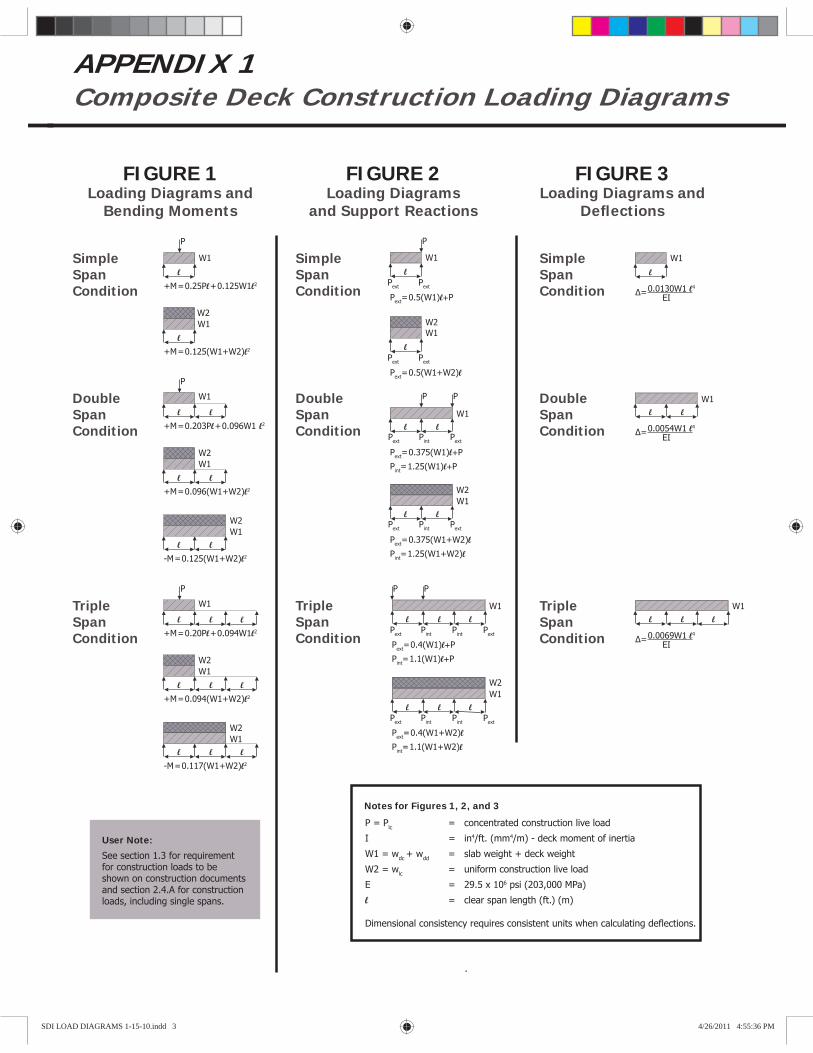
APPENDIX 1Composite Deck Construction Loading Diagrams
FIGURE 1Loading Diagrams and
Bending Moments
FIGURE 2Loading Diagrams
and Support Reactions
FIGURE 3Loading Diagrams and
Defl ections
Simple Span Condition
Double Span Condition
Triple Span Condition
Notes for Figures 1, 2, and 3
P = Plc = concentrated construction live load
I = in4/ft. (mm4/m) - deck moment of inertia
W1 = wdc + wdd = slab weight + deck weight
W2 = wlc = uniform construction live load
E = 29.5 x 10⁶ psi (203,000 MPa)
l = clear span length (ft.) (m)
Dimensional consistency requires consistent units when calculating deflections.
P
W1
+M=0.25Pl+0.125W1l2
+M=0.125(W1+W2)l2
W1 W2
P
W1
+M=0.203Pl+0.096W1 l2
+M=0.096(W1+W2)l2
W1W2
l-M=0.125(W1+W2)l2
l
l l
l l
l
l
W1W2
P
W1
+M=0.20Pl+0.094W1l2
+M=0.094(W1+W2)l2
W1W2
l-M=0.117(W1+W2)l2
l
l l
l l
W1W2
l
l
l
Simple Span Condition
Double Span Condition
Triple Span Condition
W1
l
Δ=0.0130W1 l4
EI
l
Δ=0.0054W1 l4
EI
lW1
l
Δ=0.0069W1 l4
EI
lW1
l
Simple Span Condition
Double Span Condition
Triple Span Condition
W1
l
Pext=0.5(W1+W2)l
l
Pext=0.375(W1+W2)l
Pint=1.25(W1+W2)l
lW1
l
Pext=0.4(W1+W2)l
Pint=1.1(W1+W2)l
lW1
l
Pext Pint Pext
Pext Pext
Pext Pint Pint Pext
W2
W2
W2
W1
l
Pext=0.5(W1)l+P
Pext Pext
P
l
Pext=0.375(W1)l+P
Pint=1.25(W1)l+P
lW1
Pext Pint Pext
P P
l
Pext=0.4(W1)l+P
Pint=1.1(W1)l+P
lW1
lPext Pint Pint Pext
P P
User Note:
See section 1.3 for requirement for construction loads to be shown on construction documents and section 2.4.A for construction loads, including single spans.
SDI LOAD DIAGRAMS 1-15-10.indd 3SDI LOAD DIAGRAMS 1-15-10.indd 3 4/26/2011 4:55:36 PM4/26/2011 4:55:36 PM
1
Appendix 2 2000
30 November 2011 2001
2002
Strength Determination of Composite Deck-Slab by Pre-qualified Section Method 2003 2004
A2.1 General 2005
1. This appendix provides methods for the calculation of strength of 2006
composite steel deck-slabs. It shall be permitted to use this method if steel 2007
headed stud anchors (studs) are not present on the beam flange supporting 2008
the composite steel deck, or if steel headed stud anchors are present in any 2009
quantity. 2010
2. Limitations: 2011
A. Deck shall be limited to galvanized or uncoated steel decks with 2012
embossments meeting the requirements for Type I, Type II, or 2013
Type III patterns as shown in Figure A2.1, A2.2, A2.3, and A2.4. 2014
The design embossment height, ph, shall not be less than 0.035 in 2015
(0.89 mm) and shall not be greater than 0.105 in (2.67 mm). 2016
Embossments shall not be less than 90% of the design embossment 2017
depth. 2018
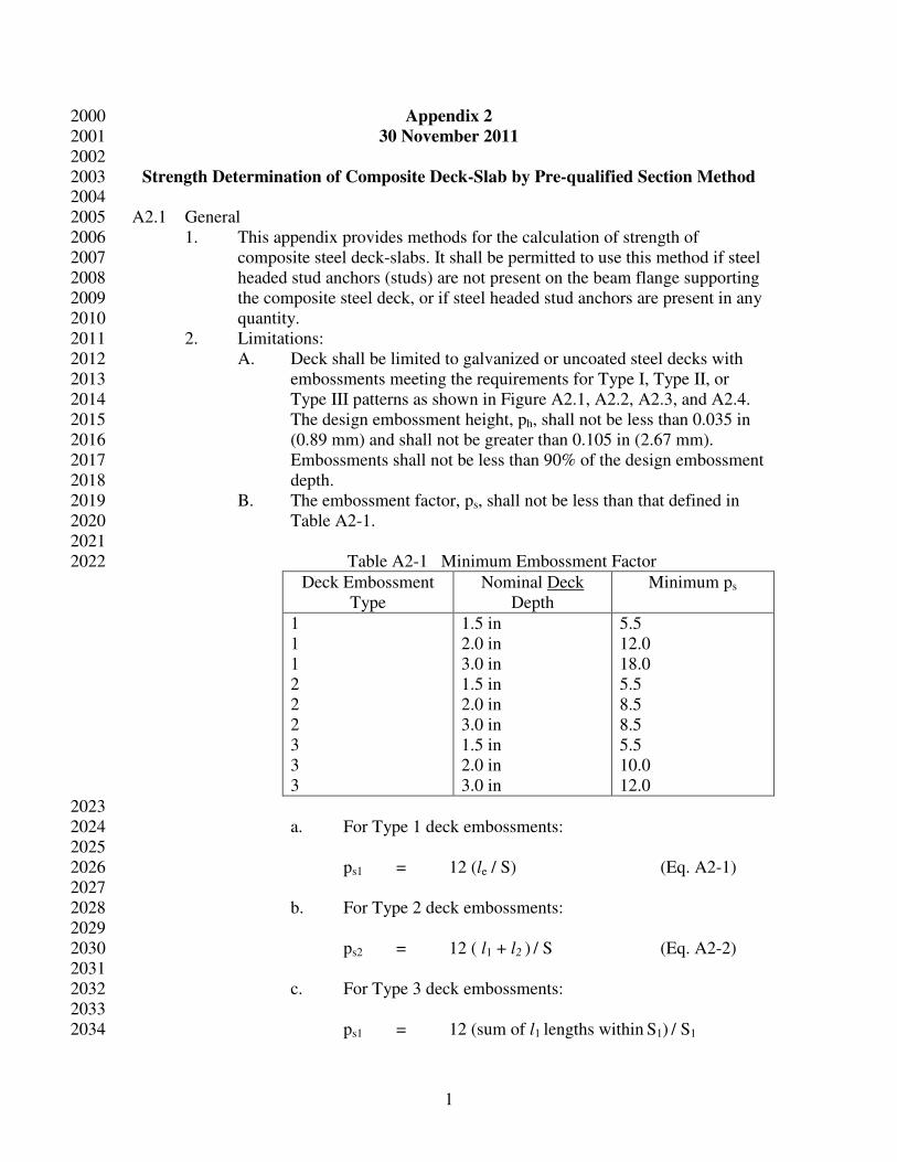
B. The embossment factor, ps, shall not be less than that defined in 2019
Table A2-1. 2020
2021
Table A2-1 Minimum Embossment Factor 2022
Deck Embossment
Type
Nominal Deck
Depth
Minimum ps
1
1
1
2
2
2
3
3
3
1.5 in
2.0 in
3.0 in
1.5 in
2.0 in
3.0 in
1.5 in
2.0 in
3.0 in
5.5
12.0
18.0
5.5
8.5
8.5
5.5
10.0
12.0
2023
a. For Type 1 deck embossments: 2024
2025
ps1 = 12 (le / S) (Eq. A2-1) 2026
2027
b. For Type 2 deck embossments: 2028
2029
ps2 = 12 ( l1 + l2 ) / S (Eq. A2-2) 2030
2031
c. For Type 3 deck embossments: 2032
2033
ps1 = 12 (sum of l1 lengths within S1) / S1 2034

2
(Eq. A2-3) 2035
2036
ps2 = 12 (sum of l2 lengths within S2) / S2 2037
(Eq. A2-4) 2038
2039 Figure A2.1 – Type 1 Embossments with length measured along centerline 2040
2041
2042 Figure A2.2 – Type 2 Embossments 2043
2044
2045 2046
Figure A2.3 – Type 3 Embossments 2047
2048
2049
3
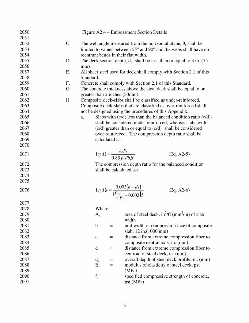
Figure A2.4 – Embossment Section Details 2050
2051
C. The web angle measured from the horizontal plane, θ, shall be 2052
limited to values between 55° and 90° and the webs shall have no 2053
reentrant bends in their flat width. 2054
D. The deck section depth, dd, shall be less than or equal to 3 in. (75 2055
mm) 2056
E. All sheet steel used for deck shall comply with Section 2.1 of this 2057
Standard. 2058
F. Concrete shall comply with Section 2.1 of this Standard. 2059
G. The concrete thickness above the steel deck shall be equal to or 2060
greater than 2 inches (50mm). 2061
H. Composite deck-slabs shall be classified as under-reinforced. 2062
Composite deck-slabs that are classified as over-reinforced shall 2063
not be designed using the procedures of this Appendix. 2064
a. Slabs with (c/d) less than the balanced condition ratio (c/d)b 2065
shall be considered under-reinforced, whereas slabs with 2066
(c/d) greater than or equal to (c/d)b shall be considered 2067
over-reinforced. The compression depth ratio shall be 2068
calculated as: 2069
2070
( )1'85.0 βdbf
FAdc
c
ys= (Eq. A2-5) 2071
The compression depth ratio for the balanced condition 2072
shall be calculated as: 2073
2074
2075
( ) ( )
( )dE
F
dhdc
s
y
db
003.0
003.0
+
−= (Eq. A2-6) 2076
2077
Where: 2078
As = area of steel deck, in2/ft (mm
2/m) of slab 2079
width 2080
b = unit width of compression face of composite 2081
slab, 12 in.(1000 mm) 2082
c = distance from extreme compression fiber to 2083
composite neutral axis, in. (mm) 2084
d = distance from extreme compression fiber to 2085
centroid of steel deck, in. (mm) 2086
dd = overall depth of steel deck profile, in. (mm) 2087
Es = modulus of elasticity of steel deck, psi 2088
(MPa) 2089
fc’ = specified compressive strength of concrete, 2090
psi (MPa) 2091
4
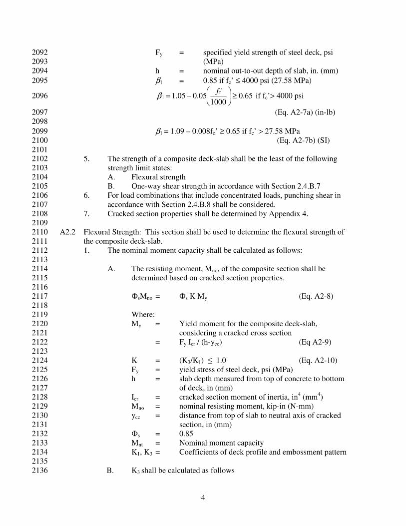
Fy = specified yield strength of steel deck, psi 2092
(MPa) 2093
h = nominal out-to-out depth of slab, in. (mm) 2094
β1 = 0.85 if fc’ ≤ 4000 psi (27.58 MPa) 2095
65.01000
'05.005.11 ≥
−=
cfβ if fc’> 4000 psi 2096
(Eq. A2-7a) (in-lb) 2097
2098
β1 = 1.09 – 0.008fc’ ≥ 0.65 if fc’ > 27.58 MPa 2099
(Eq. A2-7b) (SI) 2100
2101 5. The strength of a composite deck-slab shall be the least of the following 2102
strength limit states: 2103
A. Flexural strength 2104
B. One-way shear strength in accordance with Section 2.4.B.7 2105
6. For load combinations that include concentrated loads, punching shear in 2106
accordance with Section 2.4.B.8 shall be considered. 2107
7. Cracked section properties shall be determined by Appendix 4. 2108
2109
A2.2 Flexural Strength: This section shall be used to determine the flexural strength of 2110
the composite deck-slab. 2111
1. The nominal moment capacity shall be calculated as follows: 2112
2113
A. The resisting moment, Mno, of the composite section shall be 2114
determined based on cracked section properties. 2115
2116
ФsMno = Фs K My (Eq. A2-8) 2117
2118
Where: 2119
My = Yield moment for the composite deck-slab, 2120
considering a cracked cross section 2121
= Fy Icr / (h-ycc) (Eq A2-9) 2122
2123
K = (K3/K1) ≤ 1.0 (Eq. A2-10) 2124
Fy = yield stress of steel deck, psi (MPa) 2125
h = slab depth measured from top of concrete to bottom 2126
of deck, in (mm) 2127
Icr = cracked section moment of inertia, in4 (mm
4) 2128
Mno = nominal resisting moment, kip-in (N-mm) 2129
ycc = distance from top of slab to neutral axis of cracked 2130
section, in (mm) 2131
Фs = 0.85 2132
Mnt = Nominal moment capacity 2133
K1, K3 = Coefficients of deck profile and embossment pattern 2134
2135
B. K3 shall be calculated as follows 2136
5
2137
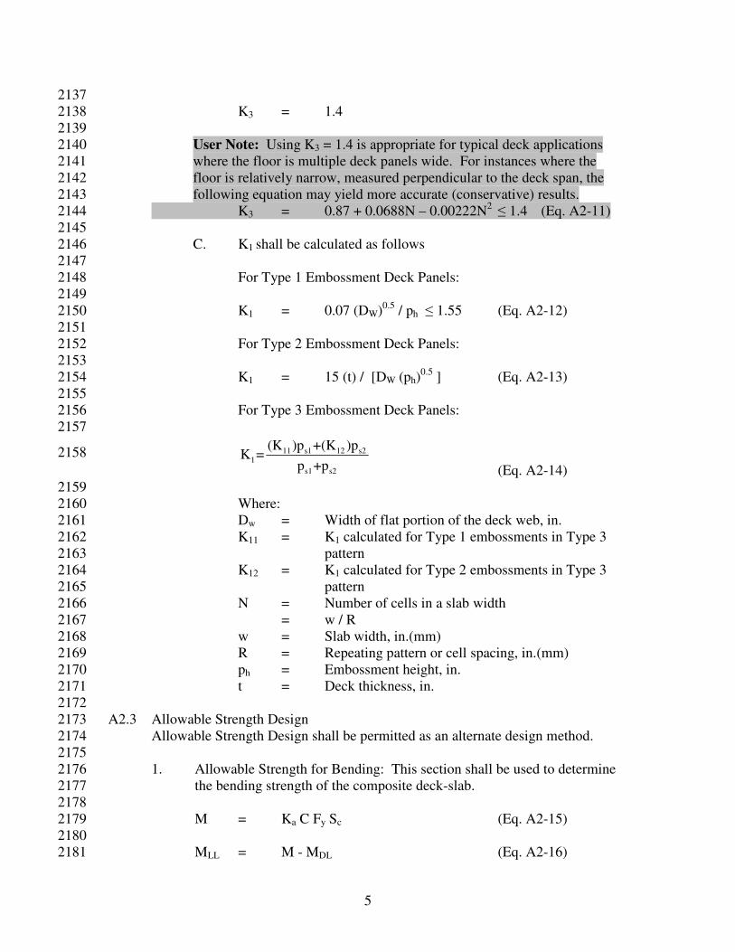
K3 = 1.4 2138
2139
User Note: Using K3 = 1.4 is appropriate for typical deck applications 2140
where the floor is multiple deck panels wide. For instances where the 2141
floor is relatively narrow, measured perpendicular to the deck span, the 2142
following equation may yield more accurate (conservative) results. 2143
K3 = 0.87 + 0.0688N – 0.00222N2
≤ 1.4 (Eq. A2-11) 2144
2145
C. K1 shall be calculated as follows 2146
2147
For Type 1 Embossment Deck Panels: 2148
2149
K1 = 0.07 (DW)0.5
/ ph ≤ 1.55 (Eq. A2-12) 2150
2151
For Type 2 Embossment Deck Panels: 2152
2153
K1 = 15 (t) / [DW (ph)0.5
] (Eq. A2-13) 2154
2155
For Type 3 Embossment Deck Panels: 2156
2157
11 s1 12 s21
s1 s2
(K )p +(K )pK =
p +p (Eq. A2-14)
2158
2159
Where: 2160
Dw = Width of flat portion of the deck web, in. 2161
K11 = K1 calculated for Type 1 embossments in Type 3 2162
pattern 2163
K12 = K1 calculated for Type 2 embossments in Type 3 2164
pattern 2165
N = Number of cells in a slab width 2166
= w / R 2167
w = Slab width, in.(mm) 2168
R = Repeating pattern or cell spacing, in.(mm) 2169
ph = Embossment height, in. 2170
t = Deck thickness, in. 2171
2172
A2.3 Allowable Strength Design 2173
Allowable Strength Design shall be permitted as an alternate design method. 2174
2175
1. Allowable Strength for Bending: This section shall be used to determine 2176
the bending strength of the composite deck-slab. 2177
2178
M = Ka C Fy Sc (Eq. A2-15) 2179
2180
MLL = M - MDL (Eq. A2-16) 2181
6
2182
Where: 2183
2184
Ka = (K3/K1) ≤ 1.0 (Eq. A2-17) 2185
2186
M = Allowable moment capacity of composite slab-deck, kip-in 2187
(N-mm) 2188
2189
MLL = Allowable superimposed load moment capacity, kip-in (N-2190
mm) 2191
2192
MDL = Positive moment caused by casting of the concrete, not 2193
including temporary construction loads, kip-in (N-mm) 2194
2195
C = 0.60 2196
2197
Fy = Yield stress of steel deck, ksi (Mpa) 2198
2199
Sc = Elastic section modulus of the fully composite deck-slab 2200
2201
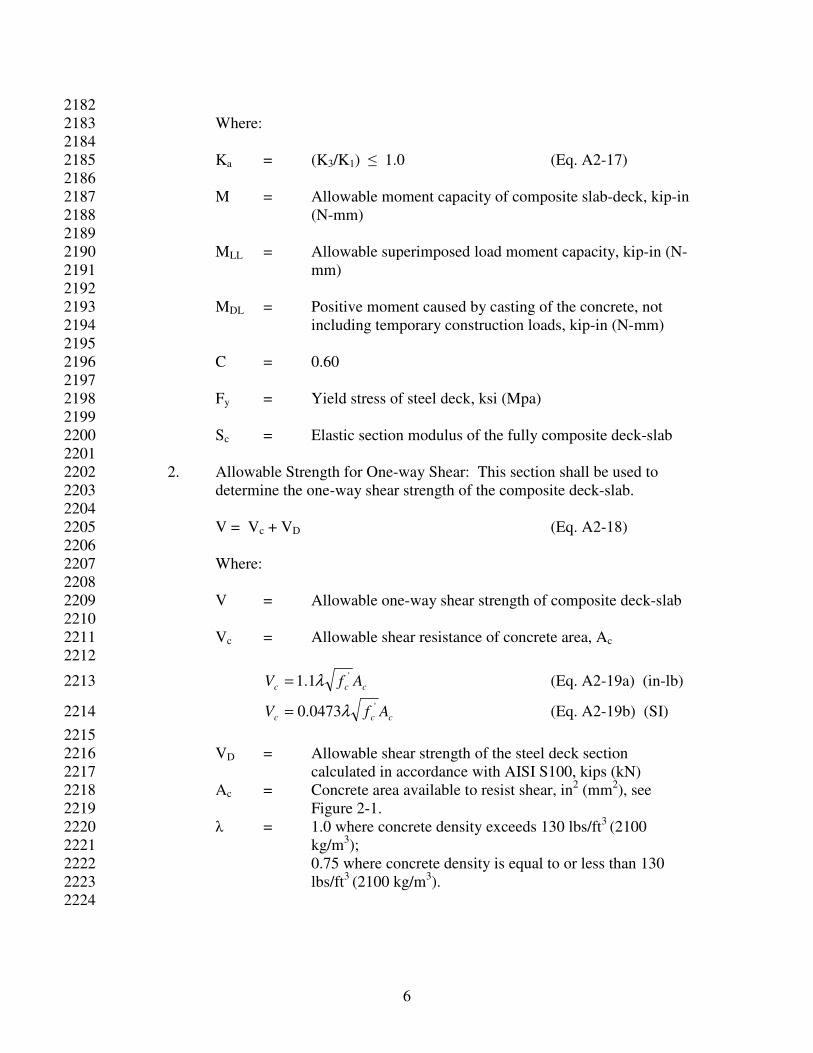
2. Allowable Strength for One-way Shear: This section shall be used to 2202
determine the one-way shear strength of the composite deck-slab. 2203
2204
V = Vc + VD (Eq. A2-18) 2205
2206
Where: 2207
2208
V = Allowable one-way shear strength of composite deck-slab 2209
2210
Vc = Allowable shear resistance of concrete area, Ac 2211
2212
ccc AfV'1.1 λ= (Eq. A2-19a) (in-lb) 2213
ccc AfV'0473.0 λ= (Eq. A2-19b) (SI) 2214
2215
VD = Allowable shear strength of the steel deck section 2216
calculated in accordance with AISI S100, kips (kN) 2217
Ac = Concrete area available to resist shear, in2 (mm
2), see 2218
Figure 2-1. 2219
λ = 1.0 where concrete density exceeds 130 lbs/ft3
(2100 2220
kg/m3); 2221
0.75 where concrete density is equal to or less than 130 2222
lbs/ft3
(2100 kg/m3). 2223
2224

7
User Note: Further description of the allowable stress design method is 2225
found in SDI-CDD, including tables that list values for the elastic section 2226
modulus. 2227

Appendix 3 3000 3001
Strength Determination of Composite Deck-Slab by Shear Bond Method 3002
30 November 2011 3003 3004
A3.1 General 3005
1. This Appendix provides methods for the calculation of strength of 3006
composite steel deck-slabs by the shear bond method. It shall be permitted 3007
to use this method if steel headed stud anchors (studs) are not present on 3008
the beam flange supporting the composite steel deck, or if steel headed 3009
stud anchors are present in any quantity. 3010
2. Limitations: 3011
A. Deck shall be limited to galvanized or top surface uncoated steel 3012
decks. 3013
B. All sheet steel used for deck shall comply with Section 2.1 of this 3014
Standard. 3015
C. Concrete shall comply with Section 2.1 of this Standard. 3016
D. The concrete thickness above the steel deck shall be equal to or 3017
greater than 2 inches (50mm). 3018
3. The strength of a composite deck-slab shall be the least of the following 3019
strength limit states: 3020
A. Shear bond resistance 3021
B. Flexural strength 3022
C. One-way shear strength in accordance with Section 2.4.B.7 3023
4. For load combinations that include concentrated loads, punching shear in 3024
accordance with Section 2.4.B.8 shall be considered. 3025
3026
A3.2 Shear bond Resistance 3027
3028
1. The ultimate shear bond resistance of a composite slab section shall be 3029
calculated using parameters determined from a testing program of full-3030
scale slab specimens in accordance with SDI-T-CD. The factored shear 3031
bond resistance (Vr) of a composite slab shall be determined as follows: 3032
3033
tVr VV φ= (Eq. A3-1) 3034
3035
Where, 3036
Vr = factored shear bond resistance, pounds/ft (N/m) of slab 3037
width, 3038
Vt = tested shear bond resistance, pounds/ft (N/m) of slab width, 3039
determined in accordance with SDI-T-CD, 3040
φv = shear bond resistance factor 3041
= 0.75 3042
3043
2. The permissible uniform load for shear bond shall be: 3044
3045
LVW tvr 2φ= (Eq. A3-2) 3046
3047
Where: 3048
L = deck design span, ft. (m) 3049
3050
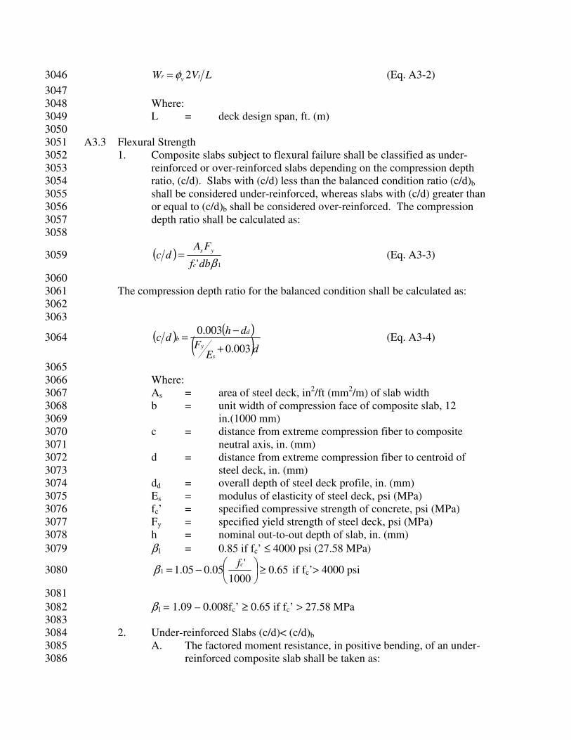
A3.3 Flexural Strength 3051
1. Composite slabs subject to flexural failure shall be classified as under-3052
reinforced or over-reinforced slabs depending on the compression depth 3053
ratio, (c/d). Slabs with (c/d) less than the balanced condition ratio (c/d)b 3054
shall be considered under-reinforced, whereas slabs with (c/d) greater than 3055
or equal to (c/d)b shall be considered over-reinforced. The compression 3056
depth ratio shall be calculated as: 3057
3058
( )1' βdbf
FAdc
c
ys= (Eq. A3-3) 3059
3060
The compression depth ratio for the balanced condition shall be calculated as: 3061
3062
3063
( ) ( )
( )dE
F
dhdc
s
y
db
003.0
003.0
+
−= (Eq. A3-4) 3064
3065
Where: 3066
As = area of steel deck, in2/ft (mm
2/m) of slab width 3067
b = unit width of compression face of composite slab, 12 3068
in.(1000 mm) 3069
c = distance from extreme compression fiber to composite 3070
neutral axis, in. (mm) 3071
d = distance from extreme compression fiber to centroid of 3072
steel deck, in. (mm) 3073
dd = overall depth of steel deck profile, in. (mm) 3074
Es = modulus of elasticity of steel deck, psi (MPa) 3075
fc’ = specified compressive strength of concrete, psi (MPa) 3076
Fy = specified yield strength of steel deck, psi (MPa) 3077
h = nominal out-to-out depth of slab, in. (mm) 3078
β1 = 0.85 if fc’ ≤ 4000 psi (27.58 MPa) 3079
65.01000
'05.005.11 ≥
−=
cfβ if fc’> 4000 psi 3080
3081
β1 = 1.09 – 0.008fc’ ≥ 0.65 if fc’ > 27.58 MPa 3082
3083
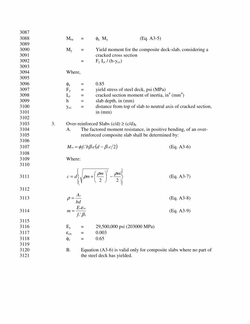
2. Under-reinforced Slabs (c/d)< (c/d)b 3084
A. The factored moment resistance, in positive bending, of an under-3085
reinforced composite slab shall be taken as: 3086
3087
Mru = φs My (Eq. A3-5) 3088
3089
My = Yield moment for the composite deck-slab, considering a 3090
cracked cross section 3091
= Fy Icr / (h-ycc) 3092
3093
Where, 3094
3095
φs = 0.85 3096
Fy = yield stress of steel deck, psi (MPa) 3097
Icr = cracked section moment of inertia, in4 (mm
4) 3098
h = slab depth, in (mm) 3099
ycc = distance from top of slab to neutral axis of cracked section, 3100
in (mm) 3101
3102
3. Over-reinforced Slabs (c/d) ≥ (c/d)b 3103
A. The factored moment resistance, in positive bending, of an over-3104
reinforced composite slab shall be determined by: 3105
3106
( )2' 11 cdcbfM ccro ββφ −= (Eq. A3-6) 3107
3108
Where: 3109
3110
−
+=
22
2mm
mdcρρ
ρ (Eq. A3-7) 3111
3112
bd
As=ρ (Eq. A3-8) 3113
1'β
ε
c
cus
f
Em = (Eq. A3-9) 3114
3115
Es = 29,500,000 psi (203000 MPa) 3116
εcu = 0.003 3117
φc = 0.65 3118
3119
B. Equation (A3-6) is valid only for composite slabs where no part of 3120
the steel deck has yielded. 3121
1
Appendix 4 4000
30 November 2011 4001 4002
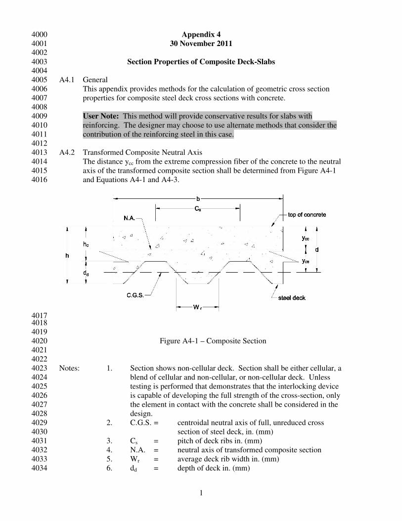
Section Properties of Composite Deck-Slabs 4003 4004
A4.1 General 4005
This appendix provides methods for the calculation of geometric cross section 4006
properties for composite steel deck cross sections with concrete. 4007
4008
User Note: This method will provide conservative results for slabs with 4009
reinforcing. The designer may choose to use alternate methods that consider the 4010
contribution of the reinforcing steel in this case. 4011
4012
A4.2 Transformed Composite Neutral Axis 4013
The distance ycc from the extreme compression fiber of the concrete to the neutral 4014
axis of the transformed composite section shall be determined from Figure A4-1 4015
and Equations A4-1 and A4-3. 4016
4017 4018
4019
Figure A4-1 – Composite Section 4020
4021
4022
Notes: 1. Section shows non-cellular deck. Section shall be either cellular, a 4023
blend of cellular and non-cellular, or non-cellular deck. Unless 4024
testing is performed that demonstrates that the interlocking device 4025
is capable of developing the full strength of the cross-section, only 4026
the element in contact with the concrete shall be considered in the 4027
design. 4028
2. C.G.S. = centroidal neutral axis of full, unreduced cross 4029
section of steel deck, in. (mm) 4030
3. Cs = pitch of deck ribs in. (mm) 4031
4. N.A. = neutral axis of transformed composite section 4032
5. Wr = average deck rib width in. (mm) 4033
6. dd = depth of deck in. (mm) 4034
2
7. h = overall slab depth in. (mm) 4035
8. hc = depth of concrete above steel deck in. (mm) 4036
4037
A4.3 Moment of Inertia of the Cracked Section 4038
4039
For the cracked moment of inertia 4040
4041
( )
ρ−ρ+ρ= nnn2dy2
cc ≤ hc (Eq. A4-1) 4042
4043
where 4044
ρ = bd
As 4045
As = area of steel deck per unit slab width in2. (mm
2) 4046
b = unit slab width (12 inches in imperial units) 4047
d = distance from top of concrete to centroid of steel deck 4048
n = modular ratio = c
s
E
E 4049
Es = 29500 ksi (203,000 MPa) 4050
4051
Ec = modulus of elasticity of concrete 4052
= wc1.5
(f’c)0.5
,ksi (0.043wc1.5
(f’c)0.5
,MPa) 4053
4054
wc = concrete unit weight, pcf (kg/m3) 4055
4056
'cf = concrete strength, ksi (MPa) 4057
4058
cccs ydy −= where ycc shall be determined from Equation A4-1. 4059
4060
The cracked moment of inertia transformed to steel, Ic ,shall be calculated using 4061
Equation A4-2. 4062
4063
sf2css
3ccc IyAy
n3
bI ++= (Eq. A4-2) 4064
4065
where 4066
Isf = moment of inertia of the full (unreduced) steel deck per unit 4067
slab width. in4. (mm
4) 4068
4069
4070
A4.4 Moment of Inertia of the Uncracked Section 4071
For the uncracked moment of inertia 4072
4073
( )
sdrsc
sddrs
2c
cc
C
bdWnAbh
C
bd5.0hdWdnAbh5.0
y
++
−++
= (Eq. A4-3) 4074
3
4075
The uncracked moment of inertia transformed to steel, Iu ,shall be calculated using 4076
Equation A4-4. 4077
4078
cccs ydy −= where ycc shall be determined from Equation A4-3. 4079
4080
( ) ( )
−−++++−+=
2dcc
2d
s
dr2csssf
2ccc
c3c
u d5.0yh12
d
nC
bdWyAIh5.0y
n
bh
n12
bhI 4081
(Eq. A4-4) 4082
4083
A4.5 Moment of Inertia of the Composite Section 4084
The moment of inertia of the composite section considered effective for deflection 4085
computations shall be calculated by Equation A4-5. 4086
4087
2
III cud
+= (Eq. A4-5) 4088
4089
4090
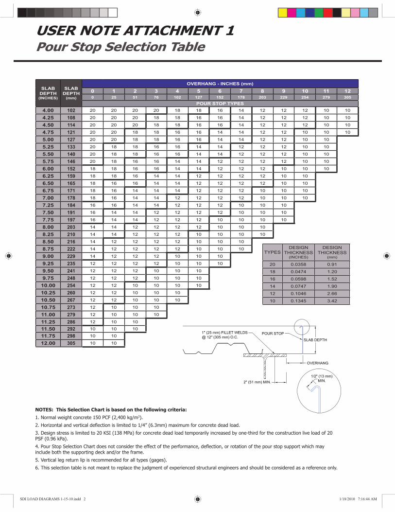
USER NOTE ATTACHMENT 1Pour Stop Selection Table
NOTES: This Selection Chart is based on the following criteria:
1. Normal weight concrete 150 PCF (2,400 kg/m3).
2. Horizontal and vertical deß ection is limited to 1/4” (6.3mm) maximum for concrete dead load.
3. Design stress is limited to 20 KSI (138 MPa) for concrete dead load temporarily increased by one-third for the construction live load of 20 PSF (0.96 kPa).
4. Pour Stop Selection Chart does not consider the effect of the performance, deß ection, or rotation of the pour stop support which may include both the supporting deck and/or the frame.
5. Vertical leg return lip is recommended for all types (gages).
6. This selection table is not meant to replace the judgment of experienced structural engineers and should be considered as a reference only.
SLAB
DEPTH(INCHES)
SLAB
DEPTH(mm)
OVERHANG - INCHES (mm)
0 1 2 3 4 5 6 7 8 9 10 11 12
0 25 51 76 102 127 152 178 203 229 254 279 305
POUR STOP TYPES
4.00 102 20 20 20 20 18 18 16 14 12 12 12 10 10
4.25 108 20 20 20 18 18 16 16 14 12 12 12 10 10
4.50 114 20 20 20 18 18 16 16 14 12 12 12 10 10
4.75 121 20 20 18 18 16 16 14 14 12 12 10 10 10
5.00 127 20 20 18 18 16 16 14 14 12 12 10 10
5.25 133 20 18 18 16 16 14 14 12 12 12 10 10
5.50 140 20 18 18 16 16 14 14 12 12 12 10 10
5.75 146 20 18 16 16 14 14 12 12 12 12 10 10
6.00 152 18 18 16 16 14 14 12 12 12 10 10 10
6.25 159 18 18 16 14 14 12 12 12 12 10 10
6.50 165 18 16 16 14 14 12 12 12 12 10 10
6.75 171 18 16 14 14 14 12 12 12 10 10 10
7.00 178 18 16 14 14 12 12 12 12 10 10 10
7.25 184 16 16 14 14 12 12 12 10 10 10
7.50 191 16 14 14 12 12 12 12 10 10 10
7.75 197 16 14 14 12 12 12 10 10 10 10
8.00 203 14 14 12 12 12 12 10 10 10
8.25 210 14 14 12 12 12 10 10 10 10
8.50 216 14 12 12 12 12 10 10 10
8.75 222 14 12 12 12 12 10 10 10
9.00 229 14 12 12 12 10 10 10
9.25 235 12 12 12 12 10 10 10
9.50 241 12 12 12 10 10 10
9.75 248 12 12 12 10 10 10
10.00 254 12 12 10 10 10 10
10.25 260 12 12 10 10 10
10.50 267 12 12 10 10 10
10.75 273 12 10 10 10
11.00 279 12 10 10 10
11.25 286 12 10 10
11.50 292 10 10 10
11.75 298 10 10
12.00 305 10 10
TYPESDESIGN
THICKNESS(INCHES)
DESIGN
THICKNESS(mm)
20 0.0358 0.91
18 0.0474 1.20
16 0.0598 1.52
14 0.0747 1.90
12 0.1046 2.66
10 0.1345 3.42
SDI LOAD DIAGRAMS 1-15-10.indd 2 1/18/2010 7:16:44 AM