Embed Size (px)
Citation preview
Intelligent monitoring system, type TECMaintenance guide
1ZSE954005-5
1ZSE954005-5.indd 1 2012-01-19 13:32
Declaration of conformity
The manufacturer ABB AB Components SE-771 80 LUDVIKA Sweden
Hereby declares that
The product Transformer Electronic Control
by design complies with the following requirements:
• EMCDirective 89/336/EEC (amendedbyDirective 91/263/EEC,Directive 92/31/EECandDirective93/68/EEC) regarding thecharacteristics intrinsic toemissionand immunity levels and
• LowVoltageDirective73/23/EEC(modifiedbyDirective93/68/EEC).
Date 2008-01-30
Signedby ......................................................................... Carl-Henrik Wigert
Title GeneralManagerTEC
ThisMaintenanceguidehasbeenproducedtoprovidetransformermanufacturers,andtheirdesignersandengineers,accesstoallthetechnicalinformationrequiredtoassistthemintheirselectionofamonitoringsystem.ItisalsointendedasaTECsysteminformationsourceforend-users.
Theinformationprovidedinthisdocumentisintendedtobegeneralanddoesnotcoverallpossibleapplications.AnyspecificapplicationnotcoveredshouldbereferreddirectlytoABB.
ABBmakesnowarrantyorrepresentationandassumesnoliabilityfortheaccuracyoftheinformationinthisdocumentorfortheuseofsuchinformation.Allinformationinthisdocumentissubjecttochangewithoutnotice.
Wereserveallrightstothisdocumentandtheinformationcontainedherein.Reproduction,useordisclosuretothirdpartieswithoutexpresspermissionisstrictlyforbidden.
©Copyright2008ABB
1ZSE954005-5.indd 2 2012-01-19 13:32

Recommended practices
ABBrecommendscarefulconsiderationofthefollowingfactorswhenmaintainingtheTransformerElectronic Control:
■ Beforeyoubeginmaintenanceworkonaunit,makesurethatthepersonnelconductingtheworkhavereadandfullyunderstoodtheInstallation and Commissioning Guide and the Technical Guideprovidedwiththeunit.
■ Toavoiddamagingtheunit,neverexceedtheoperatinglimitsstatedindeliverydocumentsandonratingplates.
■ DonotalterormodifyaunitwithoutfirstconsultingABB.
■ Followlocalandinternationalwiringregulationsatalltimes.
■ Useonlyfactory-authorizedreplacementpartsandprocedures.
WARNING, CAUTION, and NOTE
WARNINGA WARNING provides information which, if disregarded, could result in injury or death.
CAUTIONA CAUTION provides information which, if disregarded, could result in damage to the equipment.
NOTE: A NOTE provides additional information to assist in carrying out the work described.
1ZSE954005-5.indd 3 2012-01-19 13:32

1ZSE954005-5.indd 4 2012-01-19 13:32

Table of contents
1.Aboutthismanual _________________________________________________________ 71.1General _____________________________________________________________ 71.2Terminology __________________________________________________________ 71.3Relateddocumentation ________________________________________________ 7
2.Operation ________________________________________________________________ 82.1OpentheTECMonitorembeddedweb ___________________________________ 8
2.1.1ConnectthroughEthernet _________________________________________ 82.1.2ConnectthroughTC122 __________________________________________ 82.1.3Accesslevels ____________________________________________________ 8
3.Maintenanceandservice ___________________________________________________ 93.1System/softwaremaintenance ________________________________________ 9
3.1.1Sensors ________________________________________________________ 103.1.1.1Sensorscaling ______________________________________________ 103.1.1.2Addorremoveextrasignals(onlyforTECBasicandTECIntegrated) 11
3.1.2Tap-changer_____________________________________________________ 133.1.3Coolergroups ___________________________________________________ 14
3.1.3.1Settings____________________________________________________ 143.1.3.2Confirmserviceoncoolergroups ______________________________ 16
3.1.4Events __________________________________________________________ 173.1.4.1Seteventlevels _____________________________________________ 173.1.4.2Eventlist ___________________________________________________ 17
3.1.5TEC ____________________________________________________________ 183.1.5.1SetIPaddress ______________________________________________ 183.1.5.2ConfigureTEC ______________________________________________ 193.1.5.3SettimeinTEC _____________________________________________ 193.1.5.4Changepassword ___________________________________________ 20
3.1.6Reports_________________________________________________________ 213.1.6.1Statusreport _______________________________________________ 213.1.6.2Configurationreport _________________________________________ 22
3.1.7Links ___________________________________________________________ 223.2System/hardwaremaintenance ________________________________________ 23
3.2.1Changeacircuitboard ____________________________________________ 233.2.2Changetheconfigurationonthethermostat(onlyforTECBasic) ________ 233.2.3ChangelampsintheTECcabinet(onlyforTECBasic) _________________ 233.2.4Sensorfailure ___________________________________________________ 23
3.2.4.1Currentsensor ______________________________________________ 233.2.4.2Other4-20mAsensors ______________________________________ 23
3.3.3Operation _______________________________________________________ 243.2.4.3Pt100 _____________________________________________________ 24
3.3LoadfilesintotheTECwithTcFeeder ____________________________________ 243.3.1Introduction _____________________________________________________ 243.3.2Equipment ______________________________________________________ 24
3.3.3.1TcFeederuserinterface ______________________________________ 253.3.3.2Usermode _________________________________________________ 253.3.3.3Filetypes __________________________________________________ 25
3.3.4LoadtheTECsystem _____________________________________________ 263.3.5StarttheTECsystem _____________________________________________ 273.3.6Errormessages __________________________________________________ 28
Appendix 1 FrequentlyAskedQuestions(FAQ) _____________________________________________ 29
Appendix2 Spare part list _______________________________________________________________ 30
1ZSE954005-5.indd 5 2012-01-19 13:32

1ZSE954005-5.indd 6 2012-01-19 13:32
71ZSC000857-ABJen,Rev.1
1. About this manual
1.1 General
ThismanualdescribesthehardwareandsoftwarefunctionsoftheIntelligentMonitoringSystem,typeTEC.TheTECisanelectroniccontrol,monitoring,anddiagnosticdevice.
Theinformationinthismanualisintendedforoperators.ThereaderofthismanualshouldunderstandthehardwareandsoftwarefunctionalityoftheTECsystem.
1.2 Terminology
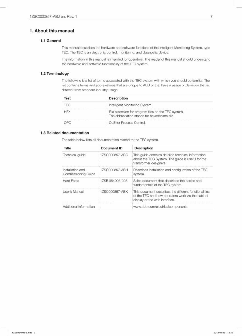
ThefollowingisalistoftermsassociatedwiththeTECsystemwithwhichyoushouldbefamiliar.ThelistcontainstermsandabbreviationsthatareuniquetoABBorthathaveausageordefinitionthatisdifferentfromstandardindustryusage.
Test Description
TEC IntelligentMonitoringSystem.
HEX FileextensionforprogramfilesontheTECsystem. Theabbreviationstandsforhexadecimalfile.
OPC OLEforProcessControl.
1.3 Related documentation
ThetablebelowlistsalldocumentationrelatedtotheTECsystem.
Title Document ID Description
Technical guide 1ZSC000857-ABG This guide contains detailed technical information abouttheTECSystem.Theguideisusefulforthetransformerdesigners.
Installation and Commissioning Guide
1ZSC000857-ABH DescribesinstallationandconfigurationoftheTECsystem.
Hard Facts 1ZSE954003-003 Sales document that describes the basics and fundamentalsoftheTECsystem.
User’sManual 1ZSC000857-ABK This document describes the different functionalities oftheTECandhowoperatorsworkviathecabinetdisplayorthewebinterface.
Additional information www.abb.com/electricalcomponents
1ZSE954005-5.indd 7 2012-01-19 13:32

8 1ZSC000857-ABJen,Rev.1
2. Operation
2.1 Open the TEC Monitor embedded web
TherearetwowaystoreachthewebinterfaceandcommunicatewiththeTEC:byconnectingviatheEthernetorbyconnectingviatheTC122.
Configure Internet Explorer for the TEC web interface
1. Click“Tools”and“InternetOptions”.
2. Clickthe“Security”tabandthenclick“DefaultLevel”andmovethesliderto“Mediumlevel”,thenclick[OK].
3. Clickthe“Privacy”tabandthenclick“DefaultLevel”andmovethesliderto“Mediumlevel”,thenclick[OK].
4. Clickthe“Advanced”tabandthencheckthecheckboxnamed“MicrosoftVM/JITcompilerforvirtualmachineenabled”,thenclick[Apply].
5. Ensurethatthe“UseHTTP1.1”and“UseHTTP1.1throughproxyconnections”arecheckedonthe“Advanced”tab.
2.1.1 Connect through Ethernet
1. OpenyourInternetExplorerwebbrowserandtypetheTECIPaddressintheURLfield.Thedefaultaddressthatisconfiguredfromstartis:192.168.1.100.FormoreinformationonhowtosetupthestaticIPaddress,seetheInstallation and Commissioning Guide,sectionPersonal Computer.
2. Thewebinterfaceshouldnowappearinthebrowser.
3. Ifaloginisrequired,choosetheappropriateuserlevelandenterthecorrectuserIDandpass-word.ThedifferentuserlevelsaredescribedintheInstallation and Commissioning Guide,section Access levels.
2.1.2 Connect through TC122
1. UsethelocalinterfacecabletoconnecttheTC122cardintheTECunittoyourcomputer’sRS232port.SeetheInstallation and Commissioning Guideforlocalwebinterfacesetup.
2. Double-clickthenewconnectionthathasbeencreatedandclick[Dial].
3. Whentheconnectionisestablished,openyourwebbrowserandtype192.168.1.100toreachthewebinterface.
4. Thewebinterfaceshouldnowappearinthebrowser.
2.1.3 Access levels
Therearethreedifferentaccesslevelsinthewebinterface:
Normal userThe Normal userlevelallowsaccesstoviewallvaluesandgraphsbutnomaintenancepages.
Advanced userThe Advanced userlevelhasthesameprivilegesastheNormaluserlevelbutalsopermityoutocleareventsfromtheeventlistandviewallmaintenancepagesexceptthechangepasswordside.
Maintenance userThe Maintenance userlevelprovidesaccesstoallpagesandpermissiontoupdatetheTECwithnewsettings.
1ZSE954005-5.indd 8 2012-01-19 13:32
91ZSC000857-ABJen,Rev.1
tec_0699
tec_0698
3. Maintenance and service
3.1 System / software maintenance
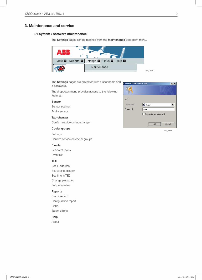
The Settings pages can be reached from the Maintenancedropdownmenu.
The Settings pages are protected with a user name and apassword.
Thedropdownmenuprovidesaccesstothefollowingfeatures:
Sensor
Sensor scaling
Add a sensor
Tap-changer
Confirmserviceontap-changer
Cooler groups
Settings
Confirmserviceoncoolergroups
Events
Seteventlevels
Eventlist
TEC
SetIPaddress
Set cabinet display
Set time in TEC
Change password
Set parameters
Reports
Status report
Configurationreport
Links
External links
Help
About
1ZSE954005-5.indd 9 2012-01-19 13:32
10 1ZSC000857-ABJen,Rev.1
tec_0700
tec_0701
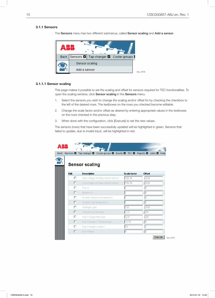
3.1.1 Sensors
The Sensorsmenuhastwodifferentsubmenus,calledSensor scaling and Add a sensor.
3.1.1.1 Sensor scaling
ThispagemakesitpossibletosetthescalingandoffsetforsensorsrequiredforTECfunctionalities.Toopenthescalingwindow,clickSensor scaling in the Sensorsmenu.
1. Selectthesensorsyouwishtochangethescalingand/oroffsetforbycheckingthecheckboxtotheleftofthedesiredrows.Thetextboxesontherowsyoucheckedbecomeeditable.
2. Changethescalefactorand/oroffsetasdesiredbyenteringappropriatevaluesinthetextboxesontherowscheckedinthepreviousstep.
3. Whendonewiththeconfiguration,click[Execute]tosetthenewvalues.
Thesensors(rows)thathavebeensuccessfullyupdatedwillbehighlightedingreen.Sensorsthatfailedtoupdate,duetoinvalidinput,willbehighlightedinred.
1ZSE954005-5.indd 10 2012-01-19 13:32

111ZSC000857-ABJen,Rev.1
tec_0152
B
A
4 mA 20mA
CAUTIONChanging the scaling on the HV and LV currents and top oil measurement can trigger the TEC trip-signal if the scale factor or offset is incorrect.
4-20 mA Scalefactor=(B-A)/16 Offset=A-(Scalefactor*4)
Pt100 Scale factor = 1 Offset=0
Pt-100sensorsarecalibratedondeliveryandneednofurthercalibration,theyhaveScalefactor1andOffset0.However,ifaPt-100sensorisnotperfectlysituated(forinstanceduetoretrofitonanoldtransformer),changingtheOffsetcanhelptoachieveamoreaccuratetemperature.
3.1.1.2 Add or remove extra signals (only for TEC Basic and TEC Integrated)
To open the Add or remove extra signalswindow,clickAdd a sensor in the Sensorsmenu.
1. Enablethedesiredsignalsbycheckingthecheckboxestotheleftofthedesiredrows.Thetext-boxesontherowsyoucheckedbecomeeditable.
2. Configurethesignalsasdesiredbyenteringappropriatevaluesinthetextboxesontherowscheckedinthepreviousstep.Toremoveasignal,enter0forboardandchannel.
3. Whendonewiththeconfigurationclick[Execute]tocommitthechanges.
IftheTEChasupdatedthevaluessuccessfullytherowwillbehighlightedingreen.Iftheupdatefails,therowswhichfailedtoupdatearehighlightedinred.
Sensor output
Realvalue (UsedinTEC)
1ZSE954005-5.indd 11 2012-01-19 13:32

12 1ZSC000857-ABJen,Rev.1
tec_0702
tec_0703
tec_0154
TC11
0
TC12
2
TC13
0
TC14
0
TC15
0
TC16
0
Ext
ra s
lot
Ext
ra s
lot
Ext
ra s
lot
Channel
TC1304-20mAsignalsareconnectedtoterminalX21...n.EachTC130boardhas8channelsandthefirstchannelisconnectedtoterminal:X2nno.:1,2.
TC140 Pt100sensorsareconnecteddirectlytothefrontoftheTC140board,toterminalX31...n.Eachboardcontains4channelsstartingwiththefirstchannelatthetopoftheboard.
See Technical Guideformoreinformation.
BoardNo. 0 1 2 3 4 5 6 7 8
Board
Theextraslotsarefilledfromlefttoright,withextraTC130,extraTC140andTC150.
Click for new sensor.
Newsensorconnected to board and channel.
Sensorscaling.Scale factor and offset for new sensor
Warning and alarmlevelfornewsensor.Therealvalueshouldbeplacedhere.”-” means no warning/alarm.
If the warning andalarmeventshall be raised whenthevalueisaboveorbeloweventlevel.
1ZSE954005-5.indd 12 2012-01-19 13:32
131ZSC000857-ABJen,Rev.1
tec_0704
tec_0705
tec_0125
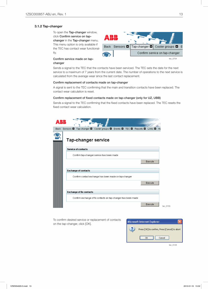
3.1.2 Tap-changer
To open the Tap-changerwindow,click Confirm service on tap-changer in the Tap-changermenu.Thismenuoptionisonlyavailableifthe TEC has contact wear functional-ity.
Confirm service made on tap-changer
SendsasignaltotheTECthatthecontactshavebeenserviced.TheTECsetsthedateforthenextservicetoamaximumof7yearsfromthecurrentdate.Thenumberofoperationstothenextserviceiscalculatedfromtheaveragewearsincethelastcontactreplacement.
Confirm replacement of contacts made on tap-changer
AsignalissenttotheTECconfirmingthatthemainandtransitioncontactshavebeenreplaced.Thecontactwearcalculationisreset.
Confirm replacement of fixed contacts made on tap-changer (only for UZ, UBB)
SendsasignaltotheTECconfirmingthatthefixedcontactshavebeenreplaced.TheTECresetsthefixedcontactwearcalculation.
Toconfirmdesiredserviceorreplacementofcontactsonthetap-changer,click[OK].
1ZSE954005-5.indd 13 2012-01-19 13:32

14 1ZSC000857-ABJen,Rev.1
tec_0706
tec_0707
3.1.3 Cooler groups
There are two entries in the Cooler groups menu: Settings and Confirm service on cooler groups.
3.1.3.1 Settings
OpenthewindowbyselectingSettings in the Cooler groupsmenu.
1ZSE954005-5.indd 14 2012-01-19 13:32

151ZSC000857-ABJen,Rev.1
tec_0727
Change settings for cooler groups
1. Changethenumberofcoolergroupstobeautomaticallyand/ortraditionallycontrolledbytheTEC.
2. Ifoneormorecoolergroupsaretobecontrolledautomatically,thetextboxesforthestarttem-peraturesofthefirstandlastcoolergroupsneedtobefilledin.
3. Toupdatethetablewiththelatestinsertedvalues,clickthe[Updatepage]button.
4. Ifoneormorecoolergroupsaretobecontrolledindividually,thetextboxesinthetableforthestart/stoptemperaturesofthecoolergroupneedtobefilledin.
5. TosetthechangedconfigurationintheTEC,clickthe[Execute]button.
Manual start of cooler groups (forced on)
Inthetoprightcornerofthecoolergroupsettingpage,allthecoolergroupsofthetransformerwillbedisplayed.Witheachcoolergroupicon,thereisa button that can be used to manually start and stopcoolergroups.Thiscanbeusefulfortestingofcoolergroupsfunctionalityduringmaintenance,anditmayalsobeusedinadvancetocooldownthetransformerbeforeaplannedoverloading.
Foreachcoolergroup,theicondisplaysthecur-rentstatusofthecoolergroup(ifitisrunningorifthereareanywarningsoralarms).Ifthecoolergrouphasbeenstartedmanually,alocksymbolwillbeshownintheupperleftcorneroftheicon,to indicate that the cooler group has been locked inrunningmode.Whenthecoolergroupismanu-allystopped,thelockwilldisappear.Thelocksymbolservesasareminderofmanuallystartedcoolinggroups,andwillbeshownonallpageswherethecoolinggroupsymbolsappear.
Thebuttonbeneatheachcoolergroupcanhavethree different texts:
■ Start-Thecoolergroupisnotrunningandcanbestartedmanually.
■ Stop-Thecoolergrouphasbeenmanuallystartedandcanbestopped.
■ Auto-Thecoolergroupisrunningduetoautomaticcoolingcontrol.Itcanthereforeneitherbestartednorstopped,sothebuttonisdeactivated.
Start a cooler group
1. Click[Start]forthecoolergrouptobestarted.
2. Thepagewillfreezeuntilthecoolinggrouphasbeensuccessfullystarted.Notethatthismaytakesometime.
NOTE: Manually started cooler groups will run until they are stopped manually.
1ZSE954005-5.indd 15 2012-01-19 13:32

16 1ZSC000857-ABJen,Rev.1
tec_0708
Stop a cooler group
1. Click[Stop]forthecoolergrouptobestopped.
2. Thepagewillfreezeuntilthecoolinggrouphasbeensuccessfullystarted.Notethatthismaytakesometime.
NOTE: If automatic cooling control is used, the number of coolers needed at the moment will always be kept running. Therefore, manually stopping a cooling group does not jeopardize the transformer
cooling.
3.1.3.2 Confirm service on cooler groups
OpenthewindowbyselectingtheConfirm service on cooler groups item in the Cooler groups menu.
1. Selectthecoolergrouptobegivenanewservicedatefromthedropdownmenu.
2. Confirmthatserviceoncoolergroupshasbeenmadebyclickingthe[Execute]button.
Iftheconfirmationwasaccepted,thecounterforTime in operation since last serviceisreset.Inthemainsiteforcoolers,youwillfindTime in operation since last service.
1ZSE954005-5.indd 16 2012-01-19 13:32

171ZSC000857-ABJen,Rev.1
tec_0709
tec_0710
3.1.4 Events
The Events menu has two entries: Set event levels and Event list.
Event type warning Thiseventtypeisthefirstindicationofabnormalorincreasingvaluesmea-suredbytheTEC.Immediateactionfromtheoperatormightnotbeneeded.
Event type alarm Oneormorevalueshavereachedthealarmlimit.Immediateactionfromtheoperatorisrequired.
Event type trip Oneormorevalueshavereachedthetriplimit.Thetripoutputisactivated.
3.1.4.1 Set event levels
In the Set event levelspageitispossibletoseteventlevelsforwarningsandalarmsfordifferentsen-sors.
OpenthewindowbyselectingtheSet event levels entry in the Eventsmenu.
1. Selectthesensortochangeintheeditcolumn.
2. ChangetheWarningorAlarmlevel.
3. Click[Execute]andtheTECwillbeupdatedwiththenewlevels.Notethat,forsecurityreasons,theTriplevelscannotbechangedfromthewebinterface.
3.1.4.2 Event list
Thisisalistofalleventsthathavebeengenerated.Iftheuserisloggedinasadvancedormainte-nanceuser,theeventscanbeacknowledged.Formoreinformation,seeUser’sManual.
1ZSE954005-5.indd 17 2012-01-19 13:32

18 1ZSC000857-ABJen,Rev.1
tec_0712
tec_0711
3.1.5 TEC
TherearefourconfigurationpagesfortheTECsystem:Set IP address, Configure cabinet display, Set time in TEC ,andChange password.
Set IP address
SetstheIPaddressfortheTECunit,OPCserver,andtheNTPserver.
Configure TEC display
Setsthelanguage,values,andtransformernametobedisplayedontheTECdisplay.
Set time in TEC
SetsthetimeintheTECtothecomputertime.
Change password
Changesthepasswordforthedifferentaccesslevels.
3.1.5.1 Set IP address
Bydefault,theTECsystemIPaddressisconfiguredto192.168.1.100.Dependingonnetworkcon-figuration,thismayneedtobechanged.If,forexample,morethanoneTECsystemisusedinthesamenetwork,atleastoneoftheIPaddressesneedstobechanged.
Toopenthewindow,clickSet IP address in the TECmenu.
1. Enterthechanges.
2. Click[Execute]tosetthechangesintheTEC.
3. Click[OK]or[Cancel]intheconfirmationquestionbox.
NOTE: If the TEC IP address is changed, you need to restart Internet Explorer and enter the new IP address in the URL field.
1ZSE954005-5.indd 18 2012-01-19 13:32

191ZSC000857-ABJen,Rev.1
tec_0713
tec_0714
3.1.5.2 Configure TEC
Toopenthewindow,clickConfigure TEC display in the TECmenu.
1. Change the transformer name to be displayed in the top right corner ofthescreen.
2. SelectvaluestobedisplayedinTECdisplay.
3. Select language to be used in TEC display.
4. Click[Execute]tosetthechangesintheTEC.
3.1.5.3 Set time in TEC
Toopenthewindow,clickSet time in TEC in the TECmenu.ThetimeinthePCandtheTECaredisplayed.Clickthe[Synchronize]buttontosetthetimeintheTECsystemtothesameasinPC.
1ZSE954005-5.indd 19 2012-01-19 13:32
20 1ZSC000857-ABJen,Rev.1
tec_0715
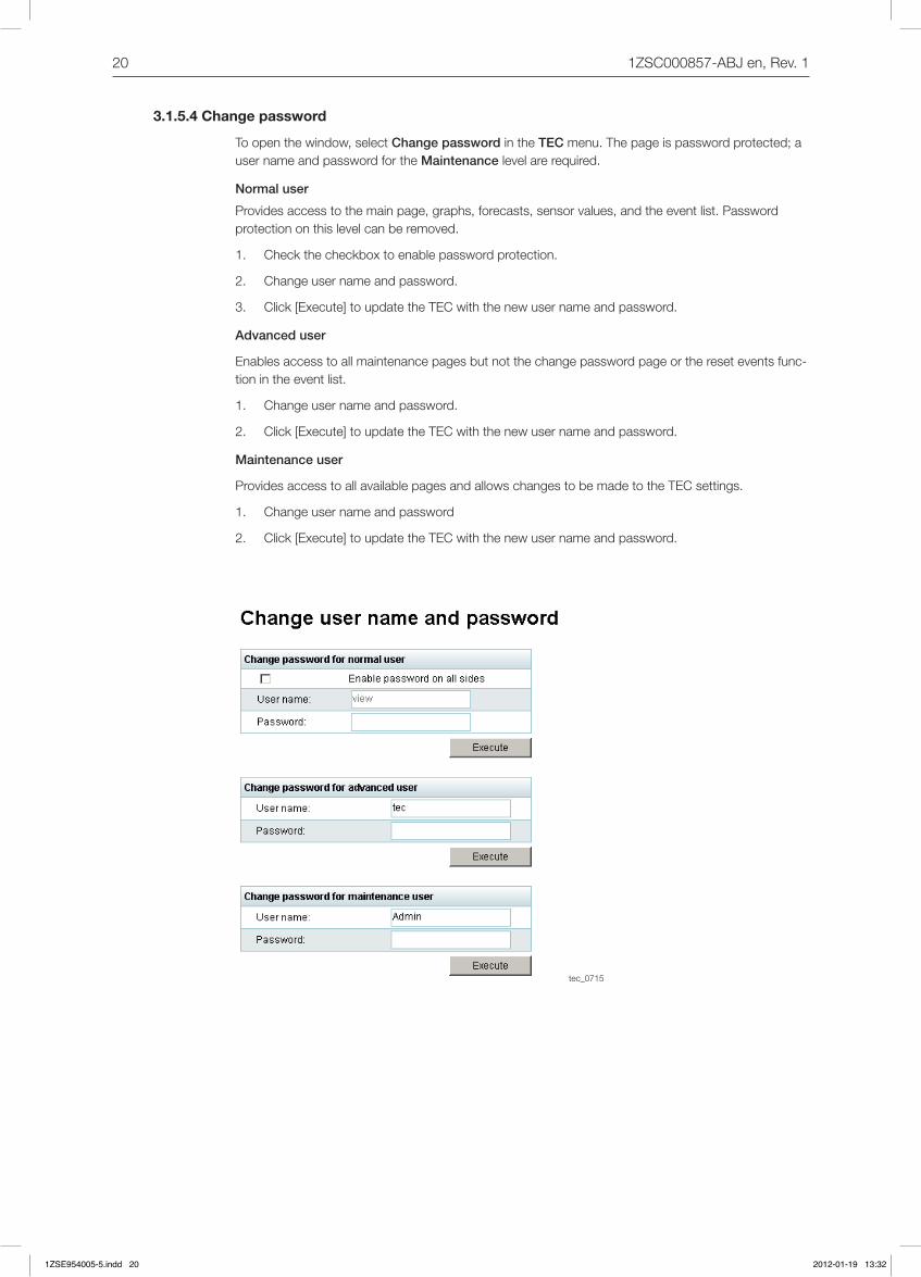
3.1.5.4 Change password
Toopenthewindow,selectChange password in the TECmenu.Thepageispasswordprotected;auser name and password for the Maintenancelevelarerequired.
Normal user
Providesaccesstothemainpage,graphs,forecasts,sensorvalues,andtheeventlist.Passwordprotectiononthislevelcanberemoved.
1. Checkthecheckboxtoenablepasswordprotection.
2. Changeusernameandpassword.
3. Click[Execute]toupdatetheTECwiththenewusernameandpassword.
Advanced user
Enablesaccesstoallmaintenancepagesbutnotthechangepasswordpageorthereseteventsfunc-tionintheeventlist.
1. Changeusernameandpassword.
2. Click[Execute]toupdatetheTECwiththenewusernameandpassword.
Maintenance user
ProvidesaccesstoallavailablepagesandallowschangestobemadetotheTECsettings.
1. Change user name and password
2. Click[Execute]toupdatetheTECwiththenewusernameandpassword.
1ZSE954005-5.indd 20 2012-01-19 13:32
211ZSC000857-ABJen,Rev.1
tec_0716
tec_0717
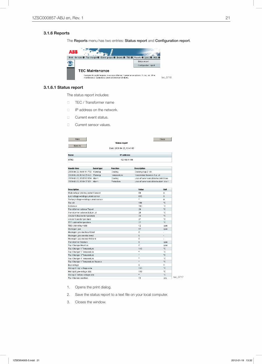
3.1.6 Reports
The Reports menu has two entries: Status report and Configuration report.
3.1.6.1 Status report
The status report includes:
■ TEC/Transformername
■ IPaddressonthenetwork.
■ Currenteventstatus.
■ Currentsensorvalues.
1. Openstheprintdialog.
2. Savethestatusreporttoatextfileonyourlocalcomputer.
3. Closesthewindow.
1ZSE954005-5.indd 21 2012-01-19 13:32
22 1ZSC000857-ABJen,Rev.1
tec_0718
tec_0660
tec_0661
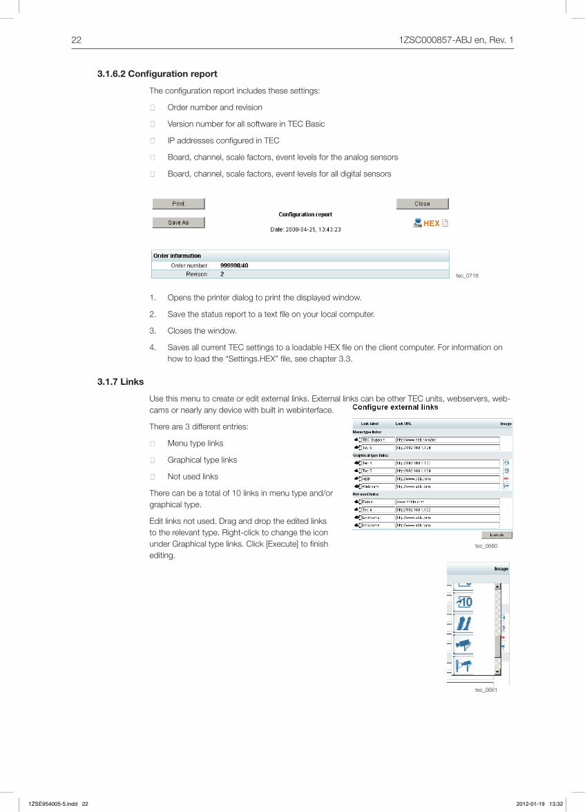
3.1.6.2 Configuration report
Theconfigurationreportincludesthesesettings:
■ Ordernumberandrevision
■ VersionnumberforallsoftwareinTECBasic
■ IPaddressesconfiguredinTEC
■ Board,channel,scalefactors,eventlevelsfortheanalogsensors
■ Board,channel,scalefactors,eventlevelsforalldigitalsensors
1. Openstheprinterdialogtoprintthedisplayedwindow.
2. Savethestatusreporttoatextfileonyourlocalcomputer.
3. Closesthewindow.
4. SavesallcurrentTECsettingstoaloadableHEXfileontheclientcomputer.Forinformationonhowtoloadthe“Settings.HEX”file,seechapter3.3.
3.1.7 Links
Usethismenutocreateoreditexternallinks.ExternallinkscanbeotherTECunits,webservers,web-camsornearlyanydevicewithbuiltinwebinterface.
Thereare3differententries:
■ Menutypelinks
■ Graphical type links
■ Notusedlinks
Therecanbeatotalof10linksinmenutypeand/orgraphicaltype.
Editlinksnotused.Draganddroptheeditedlinkstotherelevanttype.Right-clicktochangetheiconunderGraphicaltypelinks.Click[Execute]tofinishediting.
1ZSE954005-5.indd 22 2012-01-19 13:32
231ZSC000857-ABJen,Rev.1
3.2 System / hardware maintenance
3.2.1 Change a circuit board
WARNINGBefore starting any work at the TEC, the power must be disconnected.
1. DisconnectthepowerfromtheTEC.
2. AttachtheESDbracelettoagroundandyourself.
3. Removeconnectedcablesfromtheboard.
4. Removetheoldboard.
5. Insertthenewboardandtightenthescrews.
6. Connectcablestotheboard.
7. DetachtheESDbracelet.
8. ConnectthepowertotheTEC.
3.2.2 Change the configuration on the thermostat (only for TEC Basic)
1. Removethetwoscrewsontheleftandrightsidesofthedisplay.
2. Removethecontacttothedisplayandremovethedisplaypanel.
3. Useascrewdrivertoreconfigurethethermostattothedesiredtemperature.
4. Attachthedisplaycontactandthedisplaypanelwiththescrews.
3.2.3 Change lamps in the TEC cabinet (only for TEC Basic)
Thelampsare24V,10WlampswithBA15ssocket.
1. Pressthedoorcontacttobreakthepowertothelamps.
2. Replacethelamp,connectedbyabayonetsocket.
3.2.4 Sensor failure
Ifasensorfails,anAlarmorSensorErrorwillappear,dependingonwhichsensorhasfailed.TheAlarmor Sensor Error is presented in the Event listwhereitcanbereset,whenthefailingsensorhasbeencorrectedorreplaced.
3.2.4.1 Current sensor
Ifacurrentsensorsignalisunder3mAorabove20mAaSensorErroreventisgenerated.AnAlarmisgeneratedifboththeHVandtheLVsensorsarelost.
Inatwo-windingtransformer,the“lost”currentiscalculatedfromasensorotherthanthefailingsensor.Forothertypes,orifbothsensorsarefaulty,thecurrentissetto0,whichinfluencesotherfunctions,suchashot-spotandloadcalculations.
3.2.4.2 Other 4-20 mA sensors
Ifthesignalisunder3.5mAorabove22mAaSensorErroreventisgenerated.
1ZSE954005-5.indd 23 2012-01-19 13:32
24 1ZSC000857-ABJen,Rev.1
tec_0140
3.2.4.3 Pt100
Ifthetemperatureislowerthan–50°Corhigherthan150°C,thelastvalidtemperatureiskept.Ifthetemperatureexceedsasensor’smeasurablerangeforoneminute,awarningisgenerated.Ifboththetopandbottomoiltemperaturesensorshavefailed,analarmisgenerated.
Ifthetopsensorfails,theTECcanusethebottomsensortocalculateanapproximatevalueofthetopsensor.Theoppositeisalsotrueifthebottomsensorshouldfail.Forthesun/shadetemperature,afailingsensorisreplacedbytheother.Ifbothsensorsarefaulty,theirlastvaluesareusedincalcula-tions.
3.3 Load files into the TEC with TcFeeder
3.3.1 Introduction
TheTcFeedersoftwareisusedtoloadtheTECsystemsoftwareanditsconfigurationparameters.ThisguidedescribeshowtoconfigureandoperatetheTcFeedersoftware.Itisintendedforapplicationengineersandcommissioningpersonnelwhoneedtoload/starttheTECsystem.Itdoesnotneedanyinstallation;simplycopytheapplicationtotheharddrive.TheTcFeederapplicationcanbefoundontheSalesSupportPortal.
System requirements for TcFeeder
Operating system MicrosoftWindows2000/XPorhigherwith.NETframework2.0orhigherinstalled
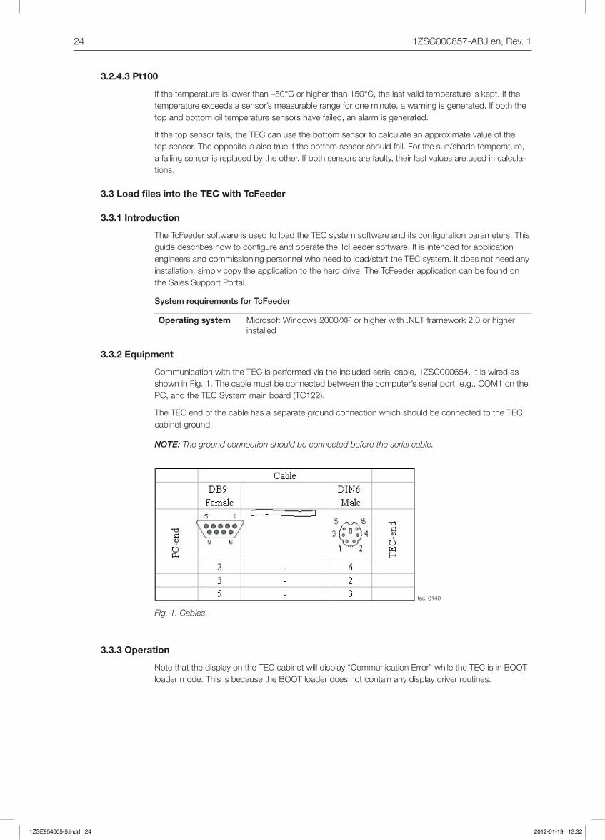
3.3.2 Equipment
CommunicationwiththeTECisperformedviatheincludedserialcable,1ZSC000654.ItiswiredasshowninFig.1.Thecablemustbeconnectedbetweenthecomputer’sserialport,e.g.,COM1onthePC,andtheTECSystemmainboard(TC122).
The TEC end of the cable has a separate ground connection which should be connected to the TEC cabinetground.
NOTE: The ground connection should be connected before the serial cable.
Fig. 1. Cables.
3.3.3 Operation
NotethatthedisplayontheTECcabinetwilldisplay“CommunicationError”whiletheTECisinBOOTloadermode.ThisisbecausetheBOOTloaderdoesnotcontainanydisplaydriverroutines.
1ZSE954005-5.indd 24 2012-01-19 13:32

251ZSC000857-ABJen,Rev.1
tec_0719
tec_0720
3.3.3.1 TcFeeder user interface
Fig.2showstheTcFeederuserinterface.DetailedinformationaboutthedifferentpartsandhowtoconfigureandoperatetheTcFeederisfoundinthefollowingsections.
Fig. 2. User interface.
3.3.3.2 User mode
TherearetwousermodesavailableintheTcFeeder,Standard and Advanced.Thisdocumentonlydescribes the Standardmode,whichshallbeusedduringcommissioningetc.Advanced mode is onlyintendedforinternaluse.DefaultusermodeisStandard.
Fig. 3. User menu.
3.3.3.3 File types
ThefiletypethatisusedfortheTECsystemistheHEXtype.Threemainfilesareusedtogetthesystemupandrunning:theApplication,ParameterandtheFilesystemfiles.Thesefilescanbemergedintoasinglefileorloadedseparately.
File descriptions:
Application Containsthesystemsoftwareandcalculations.
Parameters ConfigurationfilethatincludesalltransformerandTECspecificdata.
Filesystem Contains the embedded web interface and language translations for web anddisplay.
1ZSE954005-5.indd 25 2012-01-19 13:32
26 1ZSC000857-ABJen,Rev.1
tec_0721
tec_0722
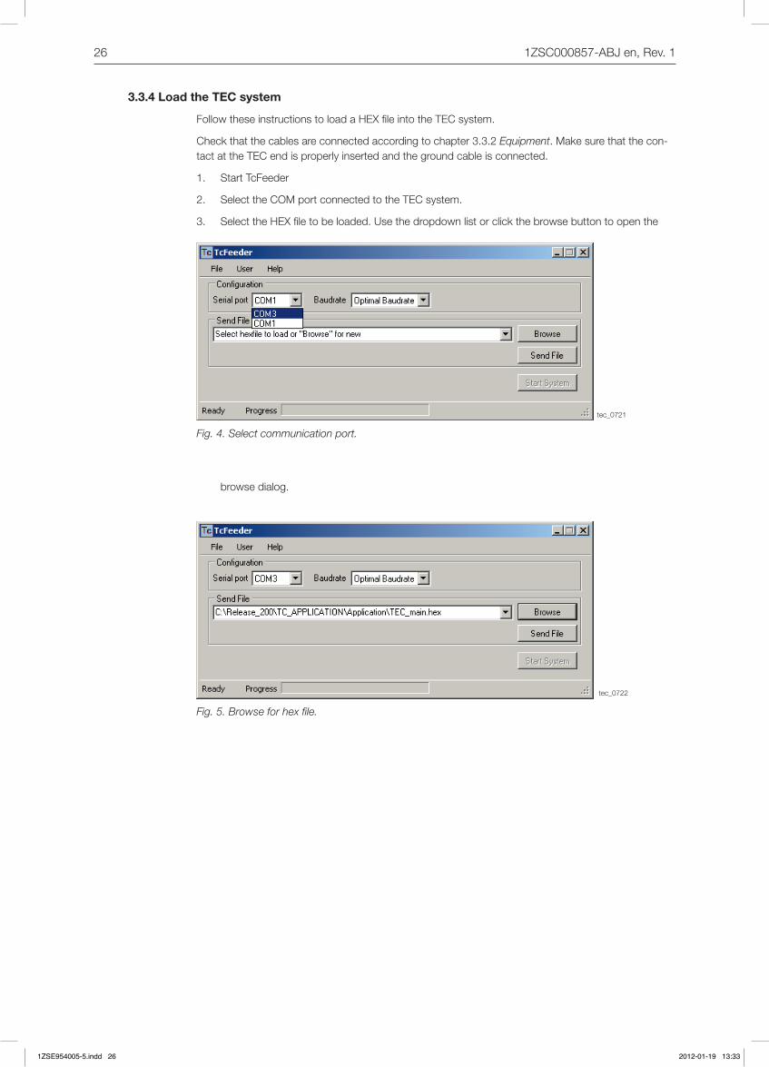
3.3.4 Load the TEC system
FollowtheseinstructionstoloadaHEXfileintotheTECsystem.
Checkthatthecablesareconnectedaccordingtochapter3.3.2Equipment.Makesurethatthecon-tactattheTECendisproperlyinsertedandthegroundcableisconnected.
1. Start TcFeeder
2. SelecttheCOMportconnectedtotheTECsystem.
3. SelecttheHEXfiletobeloaded.Usethedropdownlistorclickthebrowsebuttontoopenthe
Fig. 4. Select communication port.
browsedialog.
Fig. 5. Browse for hex file.
1ZSE954005-5.indd 26 2012-01-19 13:33
271ZSC000857-ABJen,Rev.1
tec_0723
tec_024
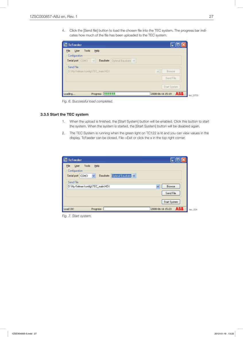
4. Clickthe[Sendfile]buttontoloadthechosenfileintotheTECsystem.Theprogressbarindi-cateshowmuchofthefilehasbeenuploadedtotheTECsystem.
Fig. 6. Successful load completed.
3.3.5 Start the TEC system
1. Whentheuploadisfinished,the[StartSystem]buttonwillbeenabled.Clickthisbuttontostartthesystem.Whenthesystemisstarted,the[StartSystem]buttonwillbedisabledagain.
2. TheTECSystemisrunningwhenthegreenlightonTC122islitandyoucanviewvaluesinthedisplay.TcFeedercanbeclosed,File->Exitorclickthexinthetoprightcorner.
Fig. 7. Start system.
1ZSE954005-5.indd 27 2012-01-19 13:33

28 1ZSC000857-ABJen,Rev.1
tec_0725
tec_0726
3.3.6 Error messages
WhenusingTcFeeder,acoupleoferrormessagesmightappear.Someofthesemessagesarede-scribedinthischapter.
Forsomecommonerrorsthesystemwilltrytorecoverautomaticallyandmakeanothertry.Iftheresultofanoperationisfailed,itispossibletoviewtheactionsthesystemhasperformedbyselecting[User/Advanced].Eachaction/actionresultstartswithatimestamp,andallinformationbeforethenexttime-stampbelongstoit.
Ifnoconnectionwiththeboardcanbeestablishedyouwillseesomeerrormessagesintheadvancedwindow,i.e.OpenfailedorCommunicationerror,seethechecklistbelow:
Forsomeunexpectederrorstherewillbenofurtherattempttofulfilltherequest,justsomeerrorinfor-mationwillbegiven.
Ifyougettheerrormessage“Openfailed”:
1. Checkthatnootherprogramisusingthesameport.
2. CheckthatyouhavechosentherightportintheTcFeeder.
3. Tryagain.
If you get the error message “Communication error”:
1. CheckthattheTECisconnectedtopower.
2. CheckthatthecableisconnectedtothecorrectserialportonthePCandthatthecontactattheTECendisproperlyconnected.
3. CheckthatyouhavechosentherightportintheTcFeeder.
4. Tryagain.
1ZSE954005-5.indd 28 2012-01-19 13:33

291ZSC000857-ABJen,Rev.1
Appendix 1 Frequently Asked Questions (FAQ)
TEC main screen is not displayed
TheTECmainscreenisnotdisplayedwhenenteringtheTECCabinetIPaddressintheInternetEx-ploreraddressfield.WhatcouldbecausingtheproblemandwhatshouldIdo?
1. CheckthatthecorrectIPaddressesareused,forboththeTECcabinetandthePC.
2. Makesurethenetworkcableisconnected.
3. CheckthattheTECcabinetisupandrunning.
TEC maintenance -> Settings screen is not displayed
TECmaintenance->Settingsscreenisnotdisplayedafterenteringuseridandpassword.WhatcouldbecausingtheproblemandwhatshouldIdo?
1. Checkthattheusernameandpasswordarecorrect.
2. CheckthattheInternetExplorersecuritysettingsarecorrect.SeeInstallation and Commissioning Guide,section2.
1ZSE954005-5.indd 29 2012-01-19 13:33
30 1ZSC000857-ABJen
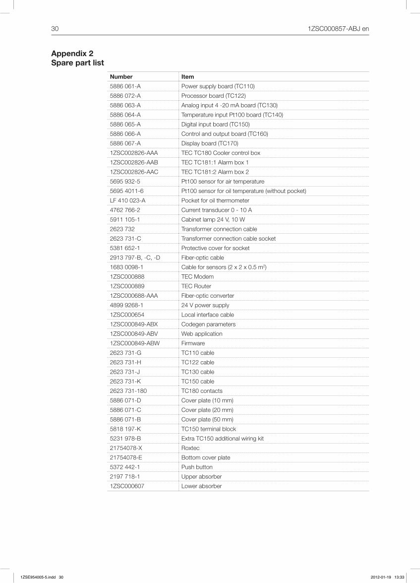
Appendix 2 Spare part list
Number Item
5886061-A Powersupplyboard(TC110)
5886072-A Processorboard(TC122)
5886063-A Analoginput4-20mAboard(TC130)
5886064-A TemperatureinputPt100board(TC140)
5886065-A Digitalinputboard(TC150)
5886066-A Controlandoutputboard(TC160)
5886067-A Displayboard(TC170)
1ZSC002826-AAA TEC TC180 Cooler control box
1ZSC002826-AAB TEC TC181:1 Alarm box 1
1ZSC002826-AAC TECTC181:2Alarmbox2
5695932-5 Pt100sensorforairtemperature
56954011-6 Pt100sensorforoiltemperature(withoutpocket)
LF410023-A Pocketforoilthermometer
4762766-2 Current transducer 0 - 10 A
5911105-1 Cabinetlamp24V,10W
2623732 Transformer connection cable
2623731-C Transformer connection cable socket
5381652-1 Protectivecoverforsocket
2913797-B,-C,-D Fiber-optic cable
16830098-1 Cableforsensors(2x2x0.5m2)
1ZSC000888 TECModem
1ZSC000889 TECRouter
1ZSC000688-AAA Fiber-opticconverter
48999268-1 24Vpowersupply
1ZSC000654 Local interface cable
1ZSC000849-ABX Codegen parameters
1ZSC000849-ABV Web application
1ZSC000849-ABW Firmware
2623731-G TC110 cable
2623731-H TC122cable
2623731-J TC130cable
2623731-K TC150cable
2623731-180 TC180 contacts
5886071-D Coverplate(10mm)
5886071-C Coverplate(20mm)
5886071-B Coverplate(50mm)
5818197-K TC150terminalblock
5231978-B ExtraTC150additionalwiringkit
21754078-X Roxtec
21754078-E Bottomcoverplate
5372442-1 Pushbutton
2197718-1 Upper absorber
1ZSC000607 Lower absorber
1ZSE954005-5.indd 30 2012-01-19 13:33

1ZSE954005-5.indd 31 2012-01-19 13:33
ABB AB Power Transformers & Shunt Reactors SE-771 80 Ludvika, Sweden Phone: +46 240 78 20 00 Fax: +46 240 131 60 E-Mail: [email protected] www.abb.com
Contact us
© C
opyr
ight
201
2 A
BB
AB
, A
ll rig
hts
rese
rved
.
1ZS
E 9
5400
5-5,
Jan
uary
201
2
1ZSE954005-5.indd 32 2012-01-19 13:33