Embed Size (px)
Citation preview
ABB
MNS Low Voltage Switchgear
Safety Aspects
intelligent value
resourceful value
communicative value
adaptable value
proactive value
innovative value
activate value

MNS is a registered trademark of ABB Schaltanlagentechnik GmbH.
ABB assumes no responsibility for any errors that may appear in this document. In no event shall ABB be liable for direct,
indirect, special, incidental, or consequential damages of any nature or kind arising from the use of this document, nor
shall ABB be liable for incidental or consequential damages arising from use of any software or hardware described in this
document.
This document and parts thereof must not be reproduced or copied without ABB's written permission, and the contents
thereof must not be imparted to a third party nor be used for any unauthorized purpose. The software described in this
document is furnished under a license and may be used, copied, or disclosed only in accordance with the terms of such
license.
All rights reserved.
Copyright 2006 © ABB Automation Products GmbH Ladenburg, Germany
This compilation of Safety Aspects applies to the MNS family
of switchgear, from the industry standard conventional, to the
latest innovative design offered by MNS iS.
Explanatory technical information as well as lists of technical
data on the above products can be obtained from the follow-
ing documents:
MNS System Guide
publication no. 1TGC902030B0201
MNS iS System Guide
publication no. 1TGC910001B0203
MNS Low Voltage Switchgear
Safety Aspects


�
Content
Content
Proven Safety “Plus” for Operators and Plant ....................6
Type Tested Switchgear Assembly – Operators Advantage .........................................................8
Arc Fault Protection ............................................................10
Degrees of Protection provided by enclosures (IP Code) .....................................................16
Internal Separation .............................................................18
Earthquake, Vibration and Shock ......................................20
Neutral conductor dimensioning .......................................21
Safety "Plus"
�
Proven Safety “Plus” for Operators and Plant
■ Universal rule to achieve a high safety level:
High protection of persons without com-
promise to the protection of the system
■ Protection classification into 2 priorities:
Priority 1:
Active Protection
The occurrence of a failure is avoided.
Priority 2:
Passive Protection
If a failure should occur it is limited to its
place of occurrence, damage due to an arc
is minimized
The fulfillment of all instructions of IEC 60439-1
assures a basic level for Personnel Protection
and System Protection. ABB goes beyond this
standard in cases where a high degree of
exposure is anticipated, or specific risks (e.g.
earthquake risk) have to be observed.
Thereby it was possible to reach an operational
availability of the installed MNS boards world-
wide of nearly 100%.
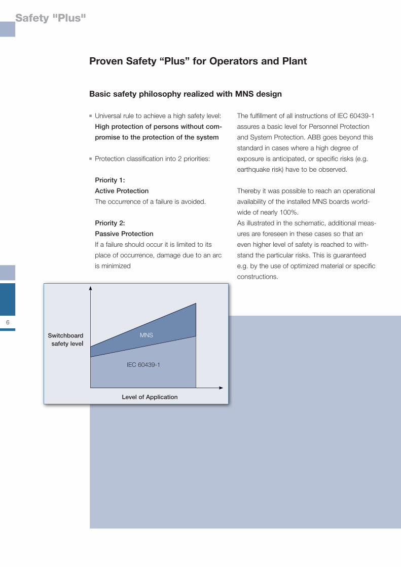
As illustrated in the schematic, additional meas-
ures are foreseen in these cases so that an
even higher level of safety is reached to with-
stand the particular risks. This is guaranteed
e.g. by the use of optimized material or specific
constructions.
Basic safety philosophy realized with MNS design
Switchboardsafety level
Level of Application
MNS
IEC 60439-1
Safety "Plus"
�
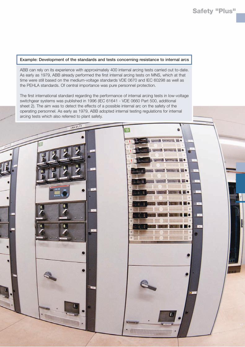
Example: Development of the standards and tests concerning resistance to internal arcs
ABB can rely on its experience with approximately 400 internal arcing tests carried out to-date. As early as 1979, ABB already performed the first internal arcing tests on MNS, which at that time were still based on the medium-voltage standards VDE 0670 and IEC 60298 as well as the PEHLA standards. Of central importance was pure personnel protection.
The first international standard regarding the performance of internal arcing tests in low-voltage switchgear systems was published in 1996 (IEC 61641 - VDE 0660 Part 500, additional sheet 2). The aim was to detect the effects of a possible internal arc on the safety of the operating personnel. As early as 1979, ABB adopted internal testing regulations for internal arcing tests which also referred to plant safety.
�
Type Tested Switchgear
Type tests
8.1.1 Type tests (see 8.2)Type tests are intended to verify compliance with the requirements laid down in this standardfor a given type of ASSEMBLY.Type tests will be carried out on a sample of such an ASSEMBLY or on such parts ofASSEMBLIES manufactured to the same or a similar design.They shall be carried out on the initiative of the manufacturer.
Type Tested Switchgear Assembly – Operators Advantage
The MNS low-voltage switchgear system is
subjected to extensive type tests in compliance
with the standards in order to ensure the high-
est possible degree of safety.
These tests are based on the most critical rep-
resentative applications of the entire product or
performance range of the switchgear with re-
spect to the test standard. The results of these
tests are applicable to the various low-voltage
switchgear and control gear assemblies (TTA)
(in accordance with IEC 60439-1; DIN EN
60439-1 / VDE 0660 Part 500).
The safety level of the standard as well as a
homogeneous quality are ensured in the way
that the corresponding design documents and
manufacturing instructions are strictly followed.
IEC �0439-1 classifies tests which verify the characteristics of an assembly into:■ type tests (acc. paragraphs 8.1.1 and 8.2)■ routine tests (acc. paragraphs 8.1.2 and 8.3).
Safety profit for operator and plant
Extended life cycle of the switchboard and equipment. Prevention of fire risks.
Avoidance of damage caused by over-voltage.
External influences can cause a short circuit. The switchboard arrangement can withstand the mechanical force of the short circuit. Limits the short circuit to the place of initiation. Prevention of fire risks.
Avoidance of fatal voltage at exposed conductive parts. Protection of personnel in case non current carrying parts accidentally become live.
Environment influences can reduce the isolation quality (e.g. polluted area). MNS can be used in severe atmosphere.
Extended lifetime for moving components and equipments. MNS far exceeds the standard requirements
Protection against live parts. Protection against penetration of liquid and solid elements. Ensures safe operation.
Type tests (related section of IEC 60439-1)
Verification of temperature-rise limits (8.2.1)
Verification of the dielectric properties (8.2.2)
Verification of the short-circuit withstand strength (8.2.3)
Verification of the effectiveness of the protective circuit (8.2.4)
Verification of clearances and creepage distances (8.2.5)
Verification of mechanical operation (8.2.6)
Verification of the degree of protection (8.2.7)
Type Tested Switchgear
9
Routine tests during production of MNS switchboards
Routine tests carried out consequently in the
factory ensure the quality of material and manu-
facturing. Guidelines like inspection instruction
and workshop checklist take into consideration
all relevant mechanical and electrical points.
8.1.2 Routine tests (see 8.3)Routine tests are intended to detect faults in materials and workmanship. They are carried out on every new ASSEMBLY after it has been assembled or on each transport unit. Another routine test at the place of installation is not required.
8.3 Routine tests8.3.1 Inspection of the ASSEMBLY including inspection of wiring and, if necessary, electrical operation test.
8.3.2 Dielectric test8.3.2.1 GeneralAll electrical equipment of the ASSEMBLY shall be connected for the test, except those appa-ratus which, according to the relevant specifications, are designed for a lower test voltage.
8.3.2.2 Application, duration and value of test voltagea) The test voltage according to 8.2.2.4 shall be applied for 1 s.b) The tests shall be made in accordance with 8.2.2.6.2 and 8.2.2.6.3.
8.3.2.3 Results to be obtained
Routine tests (related section of IEC 60439-1)
Inspection of wiring and, if necessary, electrical operation test (8.3.1)
Dielectric test (8.3.2)
Checking of protective measures and the electrical continuity of the protective circuits (8.3.3)
Safety profit for operator and plant
Dielectric test or verification of insulation resistance.
The test is considered to have been passed if there is no puncture or flashover.
Assures protection against direct and indirect contact with live parts.
10
Arc Fault Protection
Arc Fault Protection
Despite the ever growing experience of the
manufacturers and operators of switchgear
and control gear systems, there is some
residual risk of internal arc generation.
Internal arcs may be the result of:■ external influences, e.g., tools forgotten
inside the system, or any remaining material
residues after maintenance or conversion
work.■ conductive deposits on isolating supporting
elements under unfavorable environmental
conditions.
If the gases and decomposition products resul-
ting from the faults described are capable of
bridging the gap between two neighboring
phases, an arc will be fired with current intensi-
ties of several thousand amperes and tempera-
tures up to 10,000°C. These conditions will
result in a strong pressure build up inside the
switchgear.
The resistance to internal arcs refers to two
different aspects:
■ Personnel safety for the operator and
maintenance personnel■ Plant safety in order to limit the damage
within the system and to quench the internal
arc within specific areas and functional
compartments.
IEC �1�41 Guide for testing under conditions of arcing due to internal fault:
This technical report applies to enclosed low-voltage switchgear and controlgear assem- blies manufactured according to IEC 60439-1. This test is subject to an agreement between manufacturer and user. It is not considered to be a type test.
The sole purpose of this test is to assess the ability to the assembly to limit the risk of personal injury resulting from an internal arcing fault. It is intended to amend IEC 61641 to cover plant protection, too. Currently only VDE 0660 part 500 (draft 2001 March) supple- mentary sheet 2, already gives a testing guideline to limit the risk of a damage of the plant.
Priorities for the arc fault protection in MNS
Priority 1Active protection in MNSThe basic ABB MNS principle is that an arc fault should be prevented from occurring in the first place by designing and dimensioning the equipment absolute reliable.
Priority 2Passive protection in MNSLimiting of the arc to the compartment where it occurs. This minimizes the consequences of an arc if it should occur.
Arc Fault Protection
11
Subject
Compartments for ■ Busbars ■ Distribution bars■ Functional units
Busbars: If forms of separation are required:■ Protection against contact with hazardous parts.■ Protection against the passage of solid foreign bodies
Busbar■ fastening■ connections
Main contact system
IEC
IEC 60439-1 Paragraph 7.7■ Forms of internal separation and Annex D, Figure D.1■ No separation between busbars and distribution bars is required
Busbars are to be protected by internal separation:The required degree of protection shall be at least IP2X (or alternatively IPXXB).
Note:IEC 60439-1 paragraph 7.7 Forms of internal separation IP2X covers IPXXB
The IEC 60439-1 does not give requirements in terms of maintenance and sealing of busbar fastening and connections
The IEC 60439-1 does not give requirements in terms of■ Single phase encapsulation■ Main contact design
Specific solution in MNS assuring high protection for Personnel and System
Common compartment for the main busbars system. A separate com-partment for the distribution bars embedded in the MNS MFW (Multi Function Wall), single phase isolation of distribution bars.
The minimum degree of protection for internal separation is IP20
Option for maximum protection: The busbars are fully single phase insulated
Maintenance free design by thread locking screws and conical spring washers. Gas sealed connection between: ■ busbars and distribution bars ■ busbars and bars of other functional units
Single phase isolated contacts.The contact housing gives a single phase casing prior to connection of the contacts
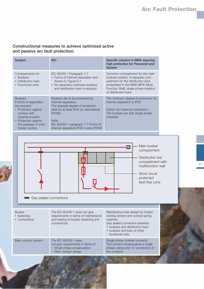
Constructional measures to achieve optimized active and passive arc fault protection:
Gas sealed connections
Short circuitprotectedfault free zone
Main busbar compartment
Distribution barcompartment with multifunction wall
12
Arc Fault Protection
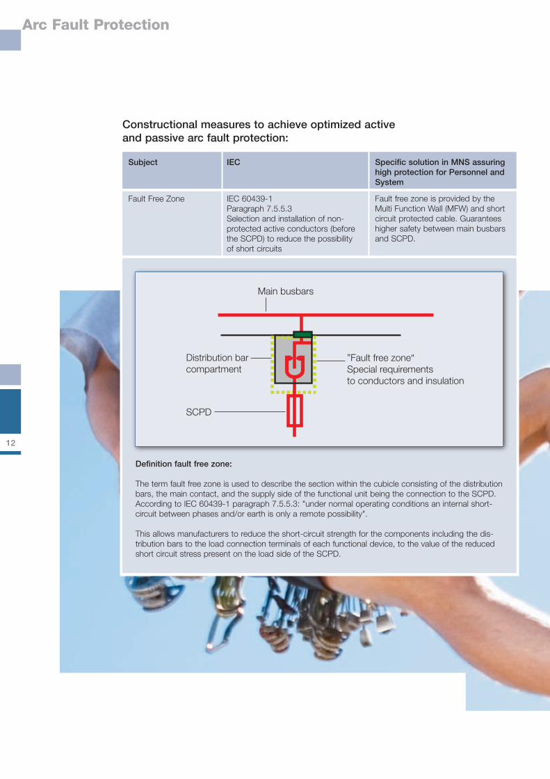
Constructional measures to achieve optimized active and passive arc fault protection:
Subject
Fault Free Zone
IEC
IEC 60439-1Paragraph 7.5.5.3Selection and installation of non-protected active conductors (before the SCPD) to reduce the possibility of short circuits
Specific solution in MNS assuring high protection for Personnel and System
Fault free zone is provided by the Multi Function Wall (MFW) and short circuit protected cable. Guarantees higher safety between main busbars and SCPD.
Main busbars
Distribution barcompartment
SCPD
”Fault free zone“Special requirementsto conductors and insulation
Definition fault free zone:
The term fault free zone is used to describe the section within the cubicle consisting of the distribution bars, the main contact, and the supply side of the functional unit being the connection to the SCPD. According to IEC 60439-1 paragraph 7.5.5.3: "under normal operating conditions an internal short-circuit between phases and/or earth is only a remote possibility".
This allows manufacturers to reduce the short-circuit strength for the components including the dis-tribution bars to the load connection terminals of each functional device, to the value of the reduced short circuit stress present on the load side of the SCPD.
13
Arc Fault Protection
Subject
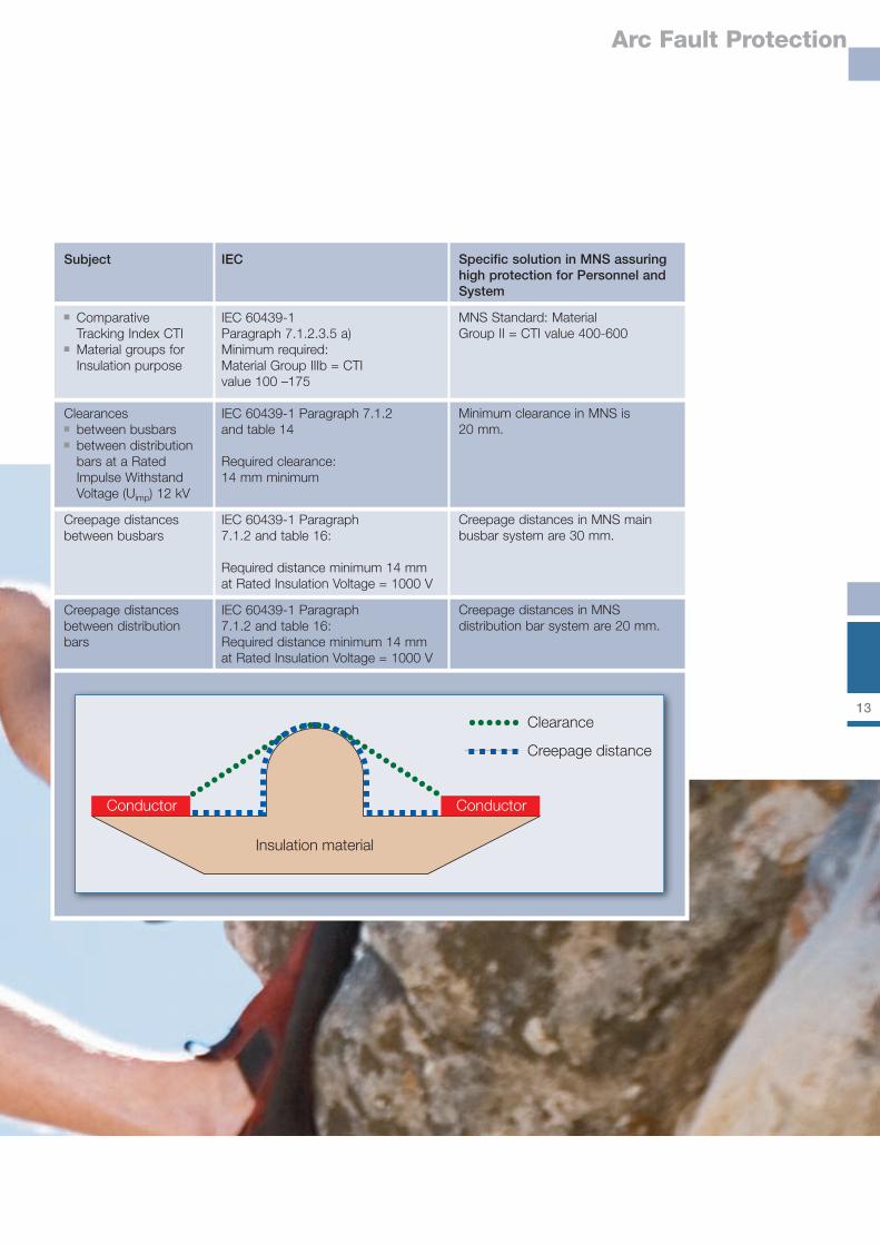
■ Comparative Tracking Index CTI■ Material groups for Insulation purpose
Clearances ■ between busbars■ between distribution bars at a Rated Impulse Withstand Voltage (Uimp) 12 kV
Creepage distances between busbars
Creepage distances between distribution bars
IEC
IEC 60439-1 Paragraph 7.1.2.3.5 a)Minimum required:Material Group IIIb = CTI value 100 –175
IEC 60439-1 Paragraph 7.1.2 and table 14
Required clearance:14 mm minimum
IEC 60439-1 Paragraph 7.1.2 and table 16:
Required distance minimum 14 mm at Rated Insulation Voltage = 1000 V
IEC 60439-1 Paragraph 7.1.2 and table 16:Required distance minimum 14 mm at Rated Insulation Voltage = 1000 V
Specific solution in MNS assuring high protection for Personnel and System
MNS Standard: Material Group II = CTI value 400-600
Minimum clearance in MNS is 20 mm.
Creepage distances in MNS main busbar system are 30 mm.
Creepage distances in MNS distribution bar system are 20 mm.
Clearance
Creepage distance
Conductor Conductor
Insulation material

14
Arc Fault Protection
Test criteria arc fault withstand
IEC �1�41 Test criterion 1-� for personnel protection:
Criterion No.
1 whether correctly secured doors, covers, etc., do not open.
2 whether parts (of the assembly), which may cause a hazard, do not fly off.
3 whether arcing does not cause holes to develop in the freely accessible external parts of the enclosure as a result of paint or stickers burning or other effects.
4 whether the indicators arranged vertically do not ignite (indicators ignited as a result of paint or stickers burning are excluded from this assessment).
5 whether the equipotential bonding arrangement for accessible parts of the enclosure is still effective.
VDE0��0 part �00 (draft 2001 march supplementary sheet 2)Test criteria for plant protection including system function protection
6 the arc must be limited to the defined area and must not re-ignite in the adjacent areas.
7 an emergency operation of the switchgear and control gear assembly must be possible when the fault has been repaired and/or the functional units of the defined area have been isolated or removed. This requirement must be evidenced by an insulation test carried out at 1.5 times the rated operating voltage for 1 min.
Test execution and results for MNS
The required values are selected for the equip-
ment, which must be able to withstand the
rated short circuit current for 0.3 s to the point
of fault arc ignition.
Results for MNS:■ Test criterion 1-5 for personnel protection
is fulfilled■ Test criterion 6-7 for system protection is
fulfilled
Note from IEC 61641 about the duration of the
tests:
When the assembly is intended to be fed from
a transformer, the permissible arc duration of
the incoming switching device should in general
be 0.3 s to allow the operation of the high-volt-
age protective equipment.
1�
Arc Fault Protection
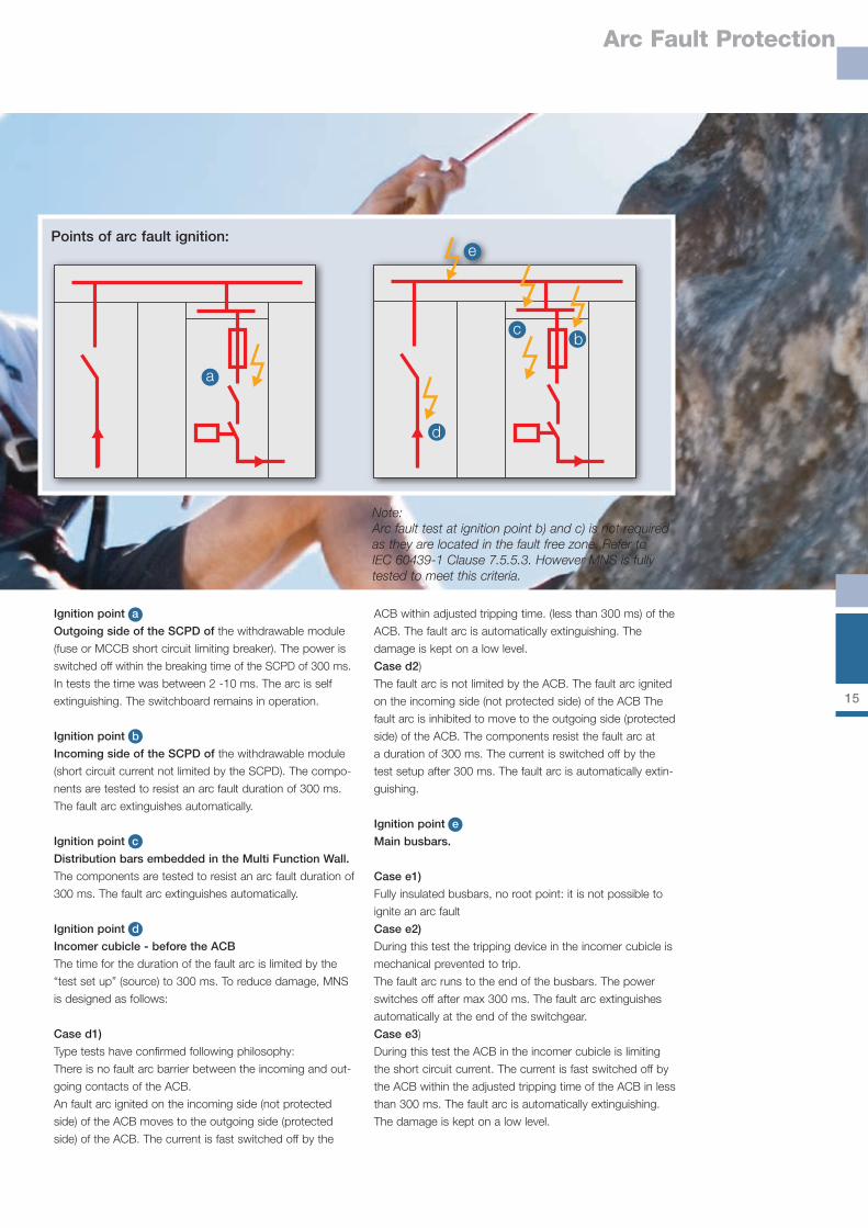
Note:Arc fault test at ignition point b) and c) is not required as they are located in the fault free zone. Refer to IEC 60439-1 Clause 7.5.5.3. However MNS is fully tested to meet this criteria.
Points of arc fault ignition:
d
cb
e
a
Ignition point a
Outgoing side of the SCPD of the withdrawable module
(fuse or MCCB short circuit limiting breaker). The power is
switched off within the breaking time of the SCPD of 300 ms.
In tests the time was between 2 -10 ms. The arc is self
extinguishing. The switchboard remains in operation.
Ignition point b
Incoming side of the SCPD of the withdrawable module
(short circuit current not limited by the SCPD). The compo-
nents are tested to resist an arc fault duration of 300 ms.
The fault arc extinguishes automatically.
Ignition point c
Distribution bars embedded in the Multi Function Wall.
The components are tested to resist an arc fault duration of
300 ms. The fault arc extinguishes automatically.
Ignition point d
Incomer cubicle - before the ACB
The time for the duration of the fault arc is limited by the
“test set up” (source) to 300 ms. To reduce damage, MNS
is designed as follows:
Case d1)
Type tests have confirmed following philosophy:
There is no fault arc barrier between the incoming and out-
going contacts of the ACB.
An fault arc ignited on the incoming side (not protected
side) of the ACB moves to the outgoing side (protected
side) of the ACB. The current is fast switched off by the
ACB within adjusted tripping time. (less than 300 ms) of the
ACB. The fault arc is automatically extinguishing. The
damage is kept on a low level.
Case d2)
The fault arc is not limited by the ACB. The fault arc ignited
on the incoming side (not protected side) of the ACB The
fault arc is inhibited to move to the outgoing side (protected
side) of the ACB. The components resist the fault arc at
a duration of 300 ms. The current is switched off by the
test setup after 300 ms. The fault arc is automatically extin-
guishing.
Ignition point e
Main busbars.
Case e1)
Fully insulated busbars, no root point: it is not possible to
ignite an arc fault
Case e2)
During this test the tripping device in the incomer cubicle is
mechanical prevented to trip.
The fault arc runs to the end of the busbars. The power
switches off after max 300 ms. The fault arc extinguishes
automatically at the end of the switchgear.
Case e3)
During this test the ACB in the incomer cubicle is limiting
the short circuit current. The current is fast switched off by
the ACB within the adjusted tripping time of the ACB in less
than 300 ms. The fault arc is automatically extinguishing.
The damage is kept on a low level.
1�
Degrees of Protection
Degrees of Protection provided by enclosures (IP Code)
Definitions
Degrees of protection provided by enclosures
of electrical equipment in accordance with
IEC 60529:
1. Protection of persons against access to
hazardous parts inside the enclosure;
2. Protection of the equipment inside the enclo-
sure against ingress of solid foreign objects;
3. Protection of the equipment inside the enclo-
sure against harmful effects due to the
ingress of water.
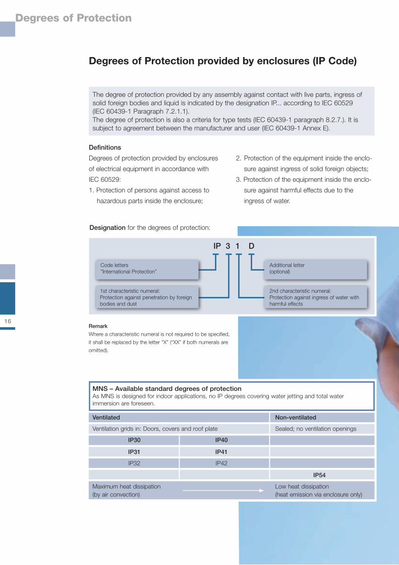
The degree of protection provided by any assembly against contact with live parts, ingress of solid foreign bodies and liquid is indicated by the designation IP... according to IEC 60529 (IEC 60439-1 Paragraph 7.2.1.1). The degree of protection is also a criteria for type tests (IEC 60439-1 paragraph 8.2.7.). It is subject to agreement between the manufacturer and user (IEC 60439-1 Annex E).
MNS – Available standard degrees of protectionAs MNS is designed for indoor applications, no IP degrees covering water jetting and total water immersion are foreseen.
Ventilated Non-ventilated
Ventilation grids in: Doors, covers and roof plate Sealed; no ventilation openings IP30 IP40 IP31 IP41 IP32 IP42 IP�4
Maximum heat dissipation Low heat dissipation(by air convection) (heat emission via enclosure only)
Remark
Where a characteristic numeral is not required to be specified,
it shall be replaced by the letter “X” (“XX” if both numerals are
omitted).
Designation for the degrees of protection:
Code letters”International Protection”
1st characteristic numeral:Protection against penetration by foreign bodies and dust
Additional letter(optional)
2nd characteristic numeral:Protection against ingress of water with harmful effects
IP 3 1 D
1�
Degrees of Protection
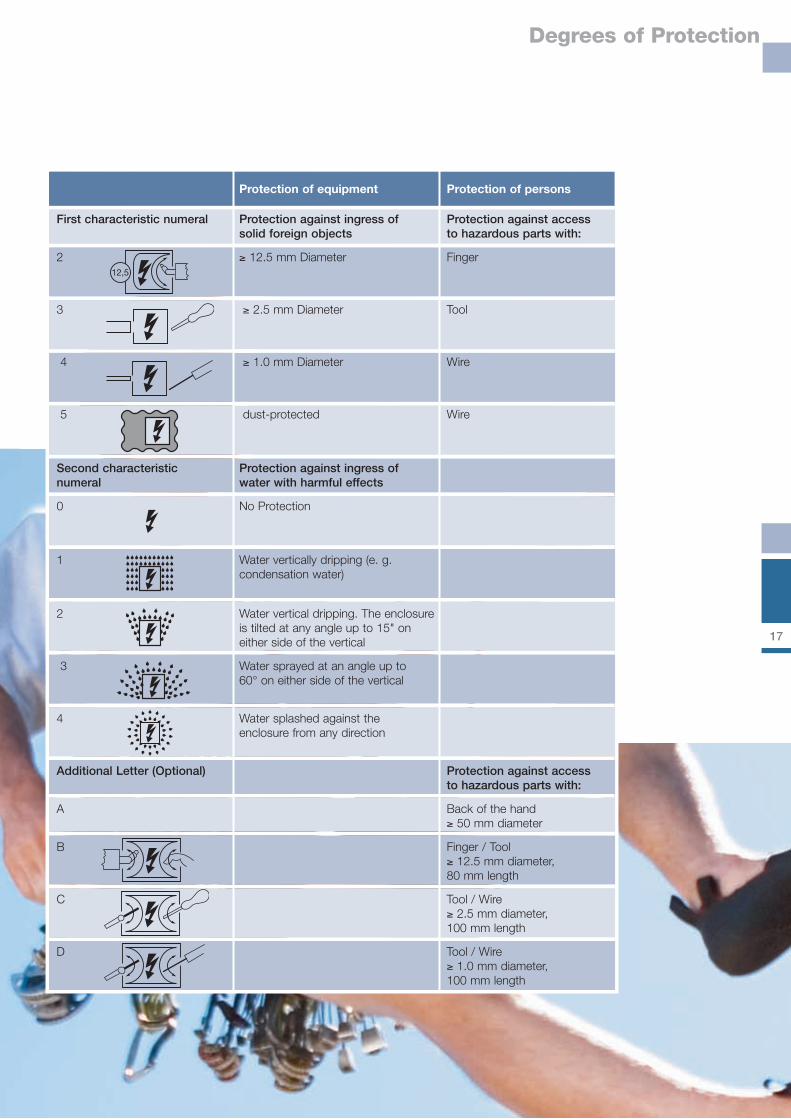
Protection of equipment Protection of persons
First characteristic numeral Protection against ingress of Protection against access solid foreign objects to hazardous parts with:
2 ≥ 12.5 mm Diameter Finger
3 ≥ 2.5 mm Diameter Tool
4 ≥ 1.0 mm Diameter Wire
5 dust-protected Wire
Second characteristic Protection against ingress ofnumeral water with harmful effects
0 No Protection
1 Water vertically dripping (e. g. condensation water)
2 Water vertical dripping. The enclosure is tilted at any angle up to 15" on either side of the vertical
3 Water sprayed at an angle up to 60° on either side of the vertical
4 Water splashed against the enclosure from any direction
Additional Letter (Optional) Protection against access to hazardous parts with:
A Back of the hand ≥ 50 mm diameter B Finger / Tool ≥ 12.5 mm diameter, 80 mm length C Tool / Wire ≥ 2.5 mm diameter, 100 mm length D Tool / Wire ≥ 1.0 mm diameter, 100 mm length
12,5
1�
Internal Separation
Internal Separation
Aim: Whenever access to a functional unit is
required (for extensions or maintenance), it
should be possible without de-energizing the
entire Low Voltage assembly.
Solution: The internal separation increases the
safety for the personnel and the plant.
Protection against direct contact can be
obtained by appropriate constructional meas-
ures on the assembly itself. The risk to cause
an internal arc failure is minimized.
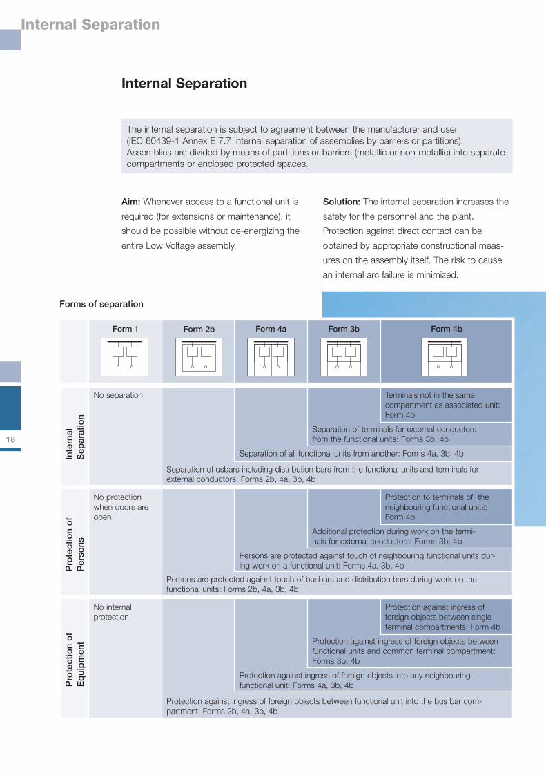
The internal separation is subject to agreement between the manufacturer and user (IEC 60439-1 Annex E 7.7 Internal separation of assemblies by barriers or partitions). Assemblies are divided by means of partitions or barriers (metallic or non-metallic) into separate compartments or enclosed protected spaces.
Inte
rnal
S
epar
atio
n
Terminals not in the same compartment as associated unit: Form 4b
No separation
Form 2b Form 4a Form 3b Form 4bForm 1
Separation of terminals for external conductors from the functional units: Forms 3b, 4b
Separation of all functional units from another: Forms 4a, 3b, 4b
Separation of usbars including distribution bars from the functional units and terminals for external conductors: Forms 2b, 4a, 3b, 4b
Pro
tect
ion
of
Per
sons
Protection to terminals of the neighbouring functional units: Form 4b
No protection when doors are open
Additional protection during work on the termi-nals for external conductors: Forms 3b, 4b
Persons are protected against touch of neighbouring functional units dur-ing work on a functional unit: Forms 4a, 3b, 4b
Persons are protected against touch of busbars and distribution bars during work on the functional units: Forms 2b, 4a, 3b, 4b
Pro
tect
ion
of
Eq
uip
men
t
Protection against ingress of foreign objects between single terminal compartments: Form 4b
No internalprotection
Protection against ingress of foreign objects between functional units and common terminal compartment: Forms 3b, 4b
Protection against ingress of foreign objects into any neighbouring functional unit: Forms 4a, 3b, 4b
Protection against ingress of foreign objects between functional unit into the bus bar com-partment: Forms 2b, 4a, 3b, 4b
Forms of separation
19
Internal Separation
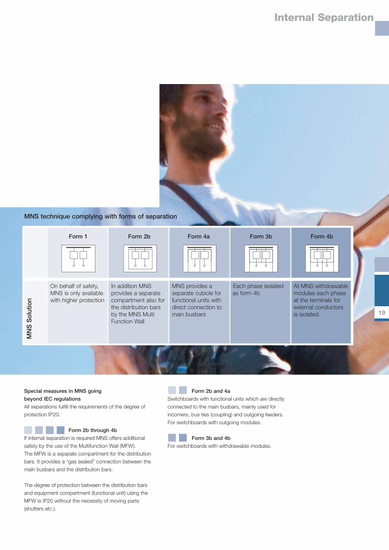
Form 2b and 4a
Switchboards with functional units which are directly
connected to the main busbars, mainly used for
incomers, bus ties (coupling) and outgoing feeders.
For switchboards with outgoing modules.
Form 3b and 4b
For switchboards with withdrawable modules.
Special measures in MNS going
beyond IEC regulations
All separations fulfill the requirements of the degree of
protection IP20.
Form 2b through 4b
If internal separation is required MNS offers additional
safety by the use of the Multifunction Wall (MFW).
The MFW is a separate compartment for the distribution
bars. It provides a “gas sealed” connection between the
main busbars and the distribution bars.
The degree of protection between the distribution bars
and equipment compartment (functional unit) using the
MFW is IP20 without the necessity of moving parts
(shutters etc.).
In addition MNS provides a separate compartment also for the distribution bars by the MNS Multi Function Wall
MNS provides a separate cubicle for functional units with direct connection to main busbars
Each phase isolated as form 4b
At MNS withdrawable modules each phase at the terminals for external conductorsis isolated.
On behalf of safety, MNS is only available with higher protection
Form 2b Form 4a Form 3b Form 4bForm 1
MNS technique complying with forms of separation
MN
S S
olut
ion
20
Earthquake, Vibration and Shock
Earthquake, Vibration and Shock
Standard Execution
According to the standards listed above, the
standard version of MNS (when erected with
floor connection, i.e. without any additional
reinforcement of the frame, the modules, etc.)
is resistant to stress caused by vibration and
shock up to 0.7 g (vertical, horizontal, diagonal).
The functional safety of the equipment, con-
tacts and connections in compliance with
the standard is guaranteed within MNS. For
example, the screwed system connections
have been proven to resist continuous stress
resulting from vibration of excavators or on
ships, providing the recommended mainte-
nance intervals are observed.
Individual solutions
In the event of additional requirements con-
cerning the earthquake resistance of a plant in
individual cases, the following data must be
provided for project engineering and, if neces-
sary, testing a specifically adjusted plant
design:■ the stress to be expected in the place
of erection■ the acceleration to be expected in the event
of an earthquake■ the frequency range and the response range
of the building
These increased demands can be met, e.g.:■ by installing the system on shock absorbers
or alternatively■ by using shock-proof equipment■ by reinforcing the frame, the enclosure and
other system parts
MNS was successfully tested according to:■ IEC 60068-2-6 (Vibration) ■ IEC 60068-2-27 (Single shock)■ Germanischer Lloyd, Lloyd’s Register of Shipping
21
Neutral conductor dimensioning
Neutral conductor dimensioning
No requirements are stipulated in IEC 60439-1 Annex E, "Items subject to agreement between manufacturer and user“, with respect to the size of the neutral conductor. However, ABB recommends to make an agreement concerning the neutral conductor design anyway, in particular, if one or several of the operating conditions described below are present.
Various electrical components used today may
cause undesirable neutral conductor currents.
These undesirable neutral conductor currents
result from harmonics and may even exceed
the value of the phase current.
This refers to, e.g.:■ Rectifiers, especially if they are equipped with
power factor correction■ Power supply units without transformers, e.g.
switched-mode power supplies of computers■ Lamps with electronic ballasts■ Phase-controlled inverters and controllers,
e.g. frequency inverters
In reality the equipment mentioned above is
often connected on the same network and uti-
lised simultaneously.
A considerable load on the neutral conductor
has to be expected based on the 3rd harmonic
(150Hz in the 50Hz system) because the phase
currents of this frequency do not equal each
other out, but rather add up, flowing back to
the generator in the neutral conductor causing
overheating.
Recommended protective measures:■ MNS offers a 4-pole busbar system as a
standard option. Preferred neutral conductor
options include 50% or 100% of the phase
conductor. In limited cases, it is also possible
to select a conductor rating up to 200%.■ It should be checked if the neutral current
can be reduced by using active ABB Third
Harmonic Filters (THF). When properly rated,
these filters eliminate undesirable neutral
conductor currents from the system.■ The inclusion of the N conductor in the safety
concept (overload trip) should be a matter-
of-course.


ABBABB Low Voltage Systems
Local contacts:
www.abb.com/mns
Publication No.: 1TGC900009B0201
Revision 01, June 2006
Editor:
ABB Automation Products
Dept. APR/RD-B
Wallstadter Str. 59
D-68526 Ladenburg, Germany