Embed Size (px)
Citation preview
NASA ISRO Synthetic Aperture Radar (NISAR)
NISAR Science Workshop – 2014Space Applications Centre
L & S Band Airborne SAR Mission
V.Manavala Ramanujam
Space Applications Centre, Ahmedabad
L&S SAR Airborne
2NISAR Science Workshop, SAC Ahmedabad – 17th & 18th Nov. 2014
L&S SAR Airborne
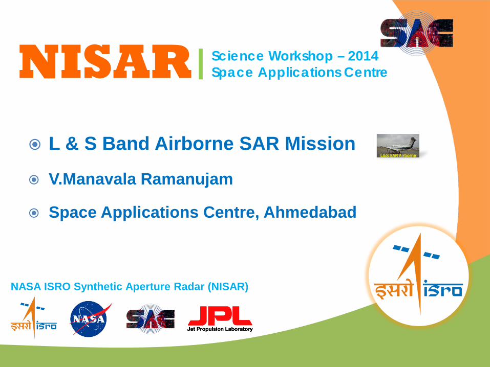
Overview
Introduction Airborne SAR activities in SAC/ISRO L& S Band Airborne SAR requirement System Specifications Imaging Geometry Block Diagram Data Products Conclusion
3NISAR Science Workshop, SAC Ahmedabad – 17th & 18th Nov. 2014
L&S SAR Airborne
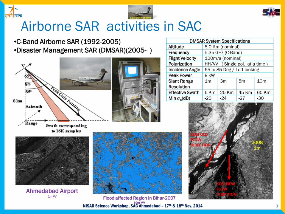
DMSAR System SpecificationsAltitude 8.0 Km (nominal)Frequency 5.35 GHz (C-Band)Flight Velocity 120m/s (nominal)Polarization HH/VV ( Single pol. at a time )Incidence Angle 65 to 85 Deg / Left lookingPeak Power 8 kWSlant Range Resolution
1m 3m 5m 10m
Effective Swath 6 Km 25 Km 45 Km 60 KmMin σo(dB) -20 -24 -27 -30
KOSI OLD FLOW DIRECTION
KOSI NEW FLOW DIRECTION
Ahmedabad Airport1m VV Flood affected Region in Bihar-2007
10m VV
20081m
•C-Band Airborne SAR (1992-2005)•Disaster Management SAR (DMSAR)(2005- )
Airborne SAR activities in SAC
4NISAR Science Workshop, SAC Ahmedabad – 17th & 18th Nov. 2014
L&S SAR Airborne
L& S Band Airborne SAR requirements To study the RCS signatures of various features at L & S
frequency bands with variable incidence angles. To demonstrate the utilization of multi-frequency SAR data in
both independent and simultaneous operation modes, from applications point of view.
To demonstrate new hardware systems like SynchronisedOscillator and Central Transmitter (SynOT), Transmit Receive Integrated Module (TRiMs), Payload Controller and Chirp Generator (PLCG), Data Formatter etc.
To verify the Synchronization methodology that is being planned in DFSS.
To check the data formatter sequence that is to be implemented in DFSS.
To establish processing methodology for PRF dithered SAR data.
5NISAR Science Workshop, SAC Ahmedabad – 17th & 18th Nov. 2014
L&S SAR Airborne
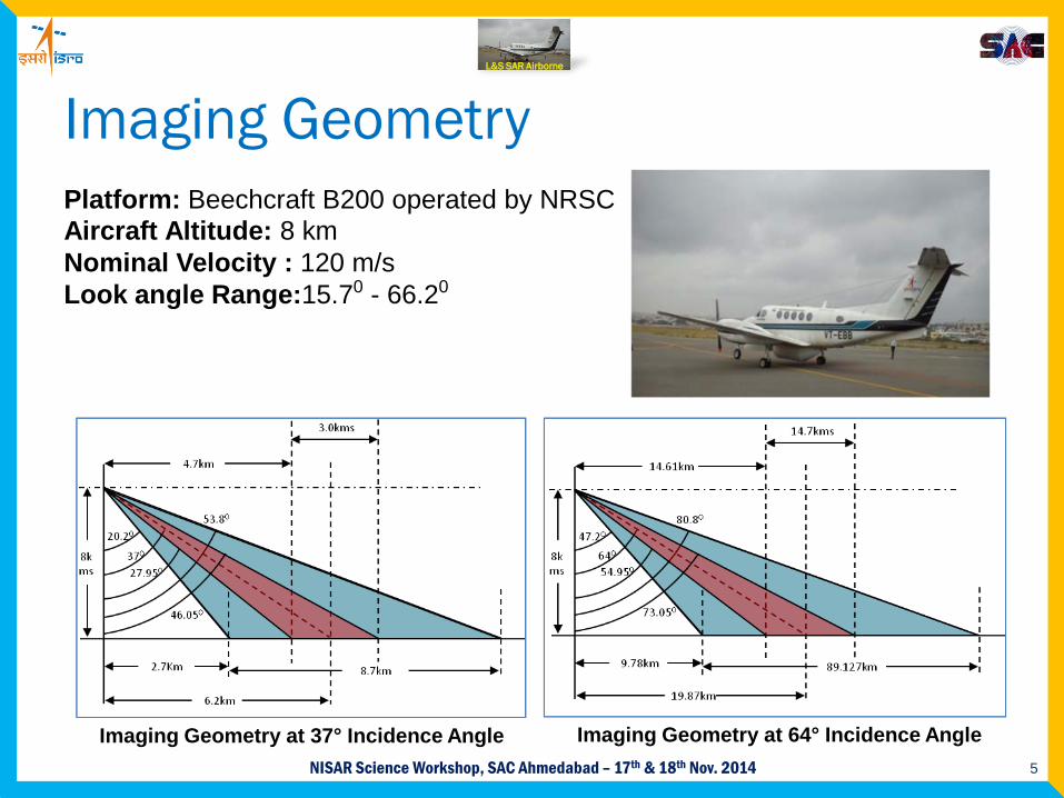
Imaging Geometry
Imaging Geometry at 37° Incidence Angle Imaging Geometry at 64° Incidence Angle
Platform: Beechcraft B200 operated by NRSCAircraft Altitude: 8 kmNominal Velocity : 120 m/sLook angle Range:15.70 - 66.20
6NISAR Science Workshop, SAC Ahmedabad – 17th & 18th Nov. 2014
L&S SAR Airborne
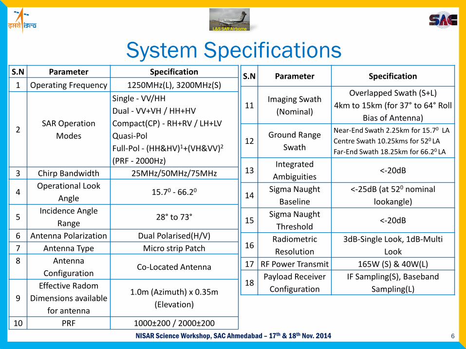
System SpecificationsS.N Parameter Specification
1 Operating Frequency 1250MHz(L), 3200MHz(S)
2SAR Operation
Modes
Single - VV/HHDual - VV+VH / HH+HVCompact(CP) - RH+RV / LH+LVQuasi-PolFull-Pol - (HH&HV)1+(VH&VV)2
(PRF - 2000Hz)3 Chirp Bandwidth 25MHz/50MHz/75MHz
4Operational Look
Angle 15.70 - 66.20
5Incidence Angle
Range28° to 73°
6 Antenna Polarization Dual Polarised(H/V)7 Antenna Type Micro strip Patch8 Antenna
ConfigurationCo-Located Antenna
9Effective Radom
Dimensions available for antenna
1.0m (Azimuth) x 0.35m (Elevation)
10 PRF 1000±200 / 2000±200
S.N Parameter Specification
11Imaging Swath
(Nominal)
Overlapped Swath (S+L) 4km to 15km (for 37° to 64° Roll
Bias of Antenna)
12Ground Range
Swath
Near-End Swath 2.25km for 15.70 LACentre Swath 10.25kms for 520 LAFar-End Swath 18.25km for 66.20 LA
13Integrated
Ambiguities<-20dB
14Sigma Naught
Baseline<-25dB (at 520 nominal
lookangle)
15Sigma Naught
Threshold<-20dB
16Radiometric Resolution
3dB-Single Look, 1dB-Multi Look
17 RF Power Transmit 165W (S) & 40W(L)
18Payload Receiver
ConfigurationIF Sampling(S), Baseband
Sampling(L)
7NISAR Science Workshop, SAC Ahmedabad – 17th & 18th Nov. 2014
L&S SAR Airborne
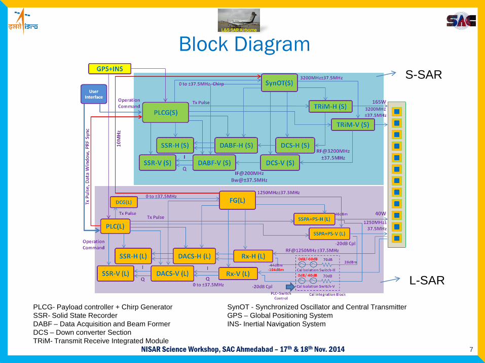
Block DiagramS-SAR
L-SAR
PLCG- Payload controller + Chirp Generator SynOT - Synchronized Oscillator and Central Transmitter SSR- Solid State Recorder GPS – Global Positioning SystemDABF – Data Acquisition and Beam Former INS- Inertial Navigation SystemDCS – Down converter SectionTRiM- Transmit Receive Integrated Module
8NISAR Science Workshop, SAC Ahmedabad – 17th & 18th Nov. 2014
L&S SAR Airborne
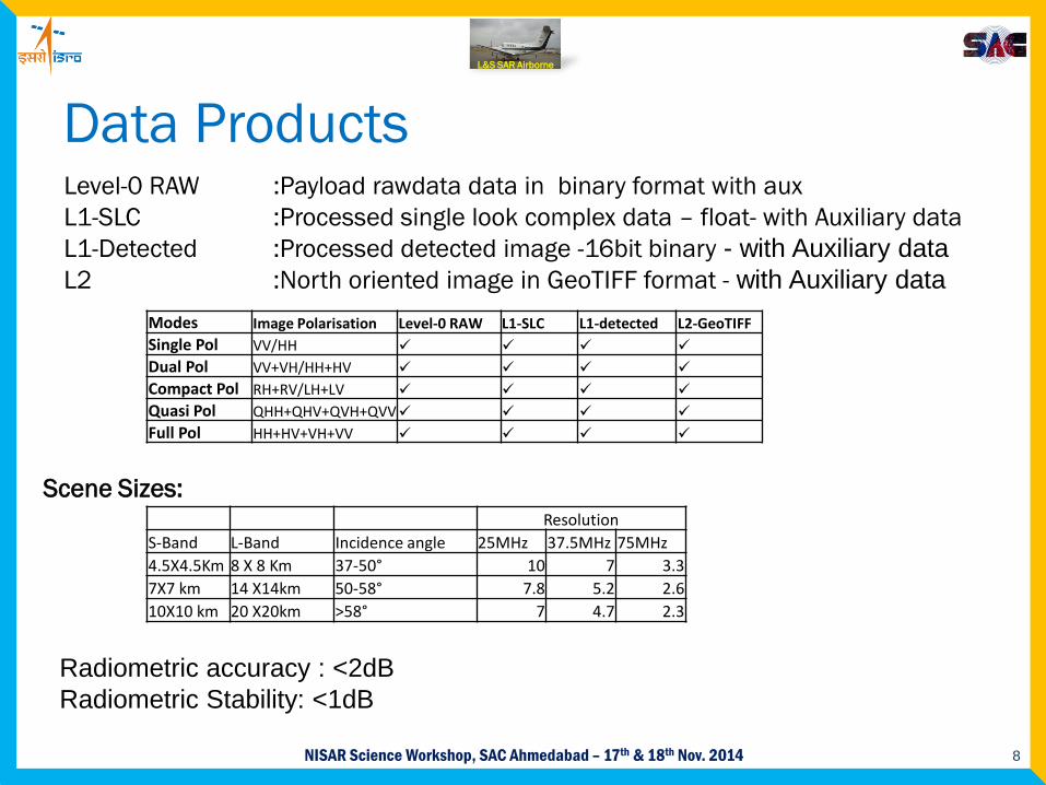
Data Products
Modes Image Polarisation Level-0 RAW L1-SLC L1-detected L2-GeoTIFFSingle Pol VV/HH Dual Pol VV+VH/HH+HV Compact Pol RH+RV/LH+LV Quasi Pol QHH+QHV+QVH+QVV Full Pol HH+HV+VH+VV
Level-0 RAW :Payload rawdata data in binary format with auxL1-SLC :Processed single look complex data – float- with Auxiliary dataL1-Detected :Processed detected image -16bit binary - with Auxiliary data L2 :North oriented image in GeoTIFF format - with Auxiliary data
Scene Sizes:Resolution
S-Band L-Band Incidence angle 25MHz 37.5MHz 75MHz4.5X4.5Km 8 X 8 Km 37-50° 10 7 3.37X7 km 14 X14km 50-58° 7.8 5.2 2.610X10 km 20 X20km >58° 7 4.7 2.3
Radiometric accuracy : <2dBRadiometric Stability: <1dB
9NISAR Science Workshop, SAC Ahmedabad – 17th & 18th Nov. 2014
L&S SAR Airborne
Conclusion This airborne SAR is a pre-cursor to the space borne
DFSS development . It will aid in the preparation of applications scientist in
the area of ecosystem, geological, disaster and coastal studies.
A number of new hardware/technologies used in NISAR will be tested in this airborne SAR.
The integrated and tested System will be delivered/Operationalized by 2015-Q3.
10NISAR Science Workshop, SAC Ahmedabad – 17th & 18th Nov. 2014
L&S SAR Airborne