Embed Size (px)
DESCRIPTION
sqs
Citation preview

Lift ControL SyStemSSIEIDrive LIFT • Inverter and Regenerative technology
The New GeNeraTioN of hiGh efficieNcy
ENG

| 2
THE ACKNOWLEDGEDINTERNATIONAL LEADER
thanks to forty years of experience, Gefran is the world leader inthe design and production of solutions for measuring, controlling,and driving industrial production processes.We have 14 branches in 12 countries and a network of over 80worldwide distributors.
QUALITY AND TECHNOLOGY
Gefran components are a concentrate of technology, the resultof constant research and of cooperation with major researchcentres.for this reason, Gefran is synonymous with quality and expertisein the design and production of:> sensors for measuring main variables such as temperature,
pressure, position and force> state-of-the-art components and solutions for indication
and control, satisfying demands for optimisation of processes and intelligent management of energy consumption
> automation platforms of various complexities> electronic drives and electric motors in ac and Dc for
all industrial automation, hVac, water treatment, lift, and photovoltaic needs.
Gefran’s know-how and experience guarantee continuity andtangible solutions.
LOW
RIs
E
HO
mE
LIf
T

3 |
AUTOMATION SOLUTIONS
LIfT CONTROL sYsTEms
the modernisation of existing systems, new systems with andwithout a machine room, and applications with synchronous andasynchronous motors with and without a reducer, can all be han-dled in a determined and simple way with Gefran’s drives.flexible and complete, thanks to a vast range of dedicated op-tions and accessories, the SieiDrive- Lift inverters represent the most rapid and immediate solution to every sector application requirement.the thousands of functioning systems throughout the world arethe best testimony to Gefran’s expertise and the high quality ofthe product.
sERVICEs
PRE AND POsT sALEsA team of Gefran experts works with the customer to select theideal product for its application and to help install and configuredevices ([email protected]).
TRAININGGefran offers a wide range of courses at different levels for thetechnical-commercial study of the Gefran product range as wellas specific courses on demand.
MARkET SEcTORS
mE
DIU
m R
IsE
HIG
H R
IsE

SieiDrive ADL300 is the result of GefrAn’s experience
in the civil lift engineering sector, gained from its com-
mitment to working in close partnership with leading
operators in the sector to develop technical solutions and
application programs.
the ADL300 integrates the most complete and advanced
lift inverter technology, and represents the ideal solution
for any type of system. Be it with gearbox and asynchro-
nous motor or gearless with synchronous permanent
magnet motor.
DeS
Cr
ipti
on
An
D D
imen
Sio
nS
| 4
ADL300
sizes ADL300 Dimensions: Width x Height x Depth Weight
mm inches kg lbs
aDL300.-1... 162 x 343 x 159 6.38 x 13.50 x 6.26 5.8 12.8
aDL300.-2... 162 x 396 x 159 6.38 x 15.59 x 6.26 7.8 17,2
aDL300.-3... 235 x 401 x 179.4 9.25 x 15.79 x 7.06 10.5 23,5
aDL300.-4... 267.6 x 616 x 276 10.53 x 24.25 x 10.87 32 70,6
aDL300.-5... 311 x 767 x 331.4 12 x 30.2 x 13.05 60 132,3
WeiGhtS AnD DimenSionS
safety” inputs for use with a single output contactor or in contactorless mode
Single output contactorthe ADL300 is certified for the use of a single output
contactor, in accordance with Uni en 81-1:1998 + A3:2009, article 9.11.3.
Safety certification for a coNTacTorLeSS operationsADL300 is CertifieD as en81-1:1998 + A3; SiL3 according to
en61800-5-2-2007.
SAfety CertifiCAtion

models ADL300A (Advanced) ADL300B (Basic)
i / o
Optional Expansion cards
• eXp-io-D4-ADL : 2 digital inputs - 2 digital outputs + enable input;
• eXp-io-D5r3-f-ADL : 5 digital inputs - 3 relays (nB: the termi-nals of this card are not extractable).
• eXp-io-D8r4-ADL : 8 digital inputs - 4 relays + enable input;
• eXp-io-D8A4r4-ADL : 8 digital inputs - 2 analog inputs - 2 analog outputs - 4 relays + enable input.
• eXp-io-D12A2r4-ADL : 8 digital inputs- 4 digital outputs - 2 analog inputs - 4 relays + enable input;
• eXp-io-D16r4-ADL : 12 digital inputs - 4 digital outputs - 4 relays + enable input.
• 8 Digital inputs (npn/pnp) + 1 Digital inputs (enable) + 4 relay outputs
• 8 Digital inputs (npn/pnp) + 1 Digital inputs (enable) + 2 analog inputs + 4 relay outputs (ADL300B-...-AD1)
encoder management
Optional Expansion cards
• eXp-De-i1r1f2-ADL : Digital encoder 3 Channels card + repeat + 2 freeze
• eXp-en/SSi-i1r1f2-ADL : Sinusoidal encoder card - Absolute enDat + repeat + 2 freeze
• eXp-hip-i1r1f2-ADL : hiperface encoder 3 Channels card + repeat + 2 freeze
• eXp-Se-i1r1f2-ADL : Sinusoidal encoder 3 Channels card + repeat + 2 freeze
• eXp-SeSC-i1r1f2-ADL: Sinusoidal SinCos encoder 3 Channels card + repeat + 2 freeze
• eXp-SeSC-i1r1-V-ADL: Sinusoidal SinCos encoder 3 Channels card + repeat (VGA connector)
• inputs for 5 Vdc ttL incremental digital encoder and absolute SinCos encoder
• inputs for 5 Vdc ttL incremental digital encoder and absolute SinCos encoder, with VGA 15 pin connector, without freeze (ADL300B-...-AD1)
GUiDe to ChoiCe of moDeLthe ADL300 is available in two configurations:
• ADL300A (Advanced) it is supplied as standard with no i/o or feedback cards, leaving the customer free to perform the appropriate configuration, choosing from an extensive range of options.
• ADL300B (BAsIC)the standard configuration is showed in the table.
Tastierino integrato
Regulation cardfor ADL300A
Removable terminals
I/O card (optional), for ADL300A only
Regulation cardfor ADL300B
(I/O and encoder input integrated)
Encoder card (optional), for ADL300A only
Integrated EMI filter(models -F)
5 |
ADL300
| 6
Gen
erA
L C
hA
rA
Cte
riS
tiC
S ADL300
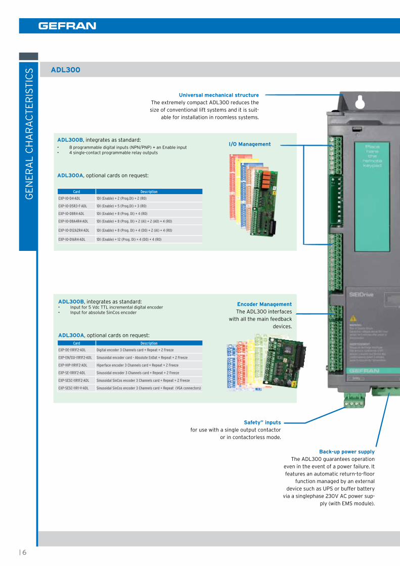
Universal mechanical structurethe extremely compact ADL300 reduces the size of conventional lift systems and it is suit-
able for installation in roomless systems.
ADL300B, integrates as standard: • input for 5 Vdc ttL incremental digital encoder• input for absolute SinCos encoder
ADL300A, optional cards on request:Card Description
EXP-DE-I1R1F2-ADL Digital encoder 3 Channels card + Repeat + 2 Freeze
EXP-EN/SSI-I1R1F2-ADL Sinusoidal encoder card - Absolute EnDat + Repeat + 2 Freeze
EXP-HIP-I1R1F2-ADL Hiperface encoder 3 Channels card + Repeat + 2 Freeze
EXP-SE-I1R1F2-ADL Sinusoidal encoder 3 Channels card + Repeat + 2 Freeze
EXP-SESC-I1R1F2-ADL Sinusoidal SinCos encoder 3 Channels card + Repeat + 2 Freeze
EXP-SESC-I1R1-V-ADL Sinusoidal SinCos encoder 3 Channels card + Repeat (VGA connectors)
Encoder managementthe ADL300 interfaces
with all the main feedback devices.
I/O management
Card Description
EXP-IO-D4-ADL 1DI (Enable) + 2 (Prog.DI) + 2 (RO)
EXP-IO-D5R3-F-ADL 1DI (Enable) + 5 (Prog.DI) + 3 (RO)
EXP-IO-D8R4-ADL 1DI (Enable) + 8 (Prog. DI) + 4 (RO)
EXP-IO-D8A4R4-ADL 1DI (Enable) + 8 (Prog. DI) + 2 (AI) + 2 (AO) + 4 (RO)
EXP-IO-D12A2R4-ADL 1DI (Enable) + 8 (Prog. DI) + 4 (DO) + 2 (AI) + 4 (RO)
EXP-IO-D16R4-ADL 1DI (Enable) + 12 (Prog. DI) + 4 (DO) + 4 (RO)
ADL300B, integrates as standard: • 8 programmable digital inputs (npn/pnp) + an enable input• 4 single-contact programmable relay outputs
ADL300A, optional cards on request:
Back-up power supplythe ADL300 guarantees operation
even in the event of a power failure. it features an automatic return-to-floor
function managed by an externaldevice such as UpS or buffer battery
via a singlephase 230V AC power sup-ply (with emS module).
safety” inputs for use with a single output contactor
or in contactorless mode.

Special adapter requiredSD-ADL, cod. S574L.
7 |
ADL300
fieldbuses the ADL300 integrates the most advanced fieldbus technology used in the lift sector:• DCp3 for use in efC (elevator floor Control)
mode• DCp4 for use in epC (elevator positioning
Control) mode• CAn with DS402 profile• CAnopen Lift (CiA®417) for lift control systems. CAN
DCP3DCP4
Configuration technology the ADL300 is fitted with rS232 serial communicationwith modbus RTU protocol.
Optional programming keypadthe optional KB-ADL programming keypad featuring full display of parameters and variables in 5 languages makes the ADL300 extremely intuitive and easy to use. it has a strip of magnetic material on the back so that it can be attached to the front of the drive or other metal surface (e.g. door of the electrical panel).the keypad can be used remotely from distances of up to 15 m. A 70 cm-long connection cable is supplied as standard. Up to 5 sets of parameters can be saved using the KB-ADL keypad and sent to other drives.
Integrated keypad the integrated programming keypad allows fast programming and immediate start-up.
• 5 line x 21 character display• Alphanumeric plaintext• Complete information regarding each
parameter• fast navigation keys • Key for displaying the last 10 parameters
that have been changed• DiSp key for rapid display of operating
parameters• Uploading-Downloading and saving of 5
complete sets of drive parameters
sD Card portthe SD memory card makes saving and loading data and configurations with the ADL300 very simple.
Lift control systemBasic and advanced lift functions are incorporated in a single product, to ensure maximum comfort for all systems at all times:• Speed control: efC (elevator floor Control) function: separate function for
independent management of short floors, landing zone, re-starting with lift not at floor and automatic deceleration point calculation.
• position control: epC (elevator positioning Control) function: separate function for independent management of direct arrival at the floor with internal position regulator and saving of floor distances (system autotuning).
• Lift sequence: typical sequence of input/output signals used in civil lift engineer-ing applications such as i/o management, braking, output contactor and door control.
• parameters in linear unit: possibility of selecting different engineering units (also with values for the US) for the main movement parameters, rpm (fpm) or m/s for speed, m/s2, m/s3 (ft/s2, ft/s3) for cabin acceleration.
• Lift mechanical parameters: mechanical system parameters such as pulley diameter and speed ratio for converting system units and weights, system for calculating inertia and speed regulation for the desired response.
• ramp generation: independent configuration of acceleration and deceleration ramp parameters and of the 4 jerk values for maximum travelling comfort in the lift cabin. two independent S-shaped ramps, selectable via digital input with 4 independent jerk settings. Dedicated deceleration ramp corresponding to the stop command.
• 1-line x 4-character alphanumerical LeD display with sign
• Simple parameter modification• menu and individual parameters displayed in
numerical format• fast navigation keys • Alarms / messages and startup wizard
displayed in text format• resetting of alarms from keypad.

| 8
model ADL300-2T ADL300-2m ADL300-4
control mode field oriented Control field oriented Control field oriented Control
Power5.5 ... 37kW
(7.5 ... 50hp)1.1 ... 5.5kW
(1.5 ... 7.5hp)4 ... 75kW
(5 ... 100hp)
Voltage3 x 200-230Vac, ±10%
50/60hz
1 x 200 Vac, ±10%1 x 230 Vac, -15%+10%
50/60hz
3 x 230-400-480Vac, -15%+10%, 50/60hz
Motor type Asynchronous / Synchronous Asynchronous / Synchronous Asynchronous / Synchronous
Speed control (accuracy)
± 0.01% motor rated speed (1) ± 0.01% motor rated speed (1) ± 0.01% motor rated speed (1)
analog inputs ADL300B: 0; ADL300A: upon reques ADL300B: 0; ADL300A: upon reques ADL300B: 0; ADL300A: upon reques
analog outputs ADL300B: 0; ADL300A: upon reques ADL300B: 0; ADL300A: upon reques ADL300B: 0; ADL300A: upon reques
Digital inputs ADL300B: 8 + 1 enable ADL300A: upon reques
ADL300B: 8 + 1 enable ADL300A: upon reques
ADL300B: 8 + 1 enable ADL300A: upon reques
Digital outputs ADL300B : 4 (relay) ADL300A: upon reques
ADL300B : 4 (relay) ADL300A: upon reques
ADL300B : 4 (relay) ADL300A: upon reques
overload up to 200% in * 10” (up to 11kW) up to 180% in * 10” (≥ 15kW) up to 200% in * 3” up to 200% in * 10” (up to 22kW)
up to 180% in * 10” (≥ 30kW)
Max output frequency 300hz 300hz 300hz
eMi filterintegrated (ADL300.-f models)
(en 1201; en 61800-3 category C2 and C3)
optional external (en 1201; en 61800-3 category C2
and C3)
integrated (en 1201; en 61800-3 category C2
and C3)
choke DC side choke: noAC side choke: external optional no
DC side choke: integrated (sizes ≥ 4300), external optional on lower
sizesAC side choke: external optional
Braking unit integrated with external resistor integrated with external resistor integrato fino a 55kW con resistenza esterna
Port for SD card yes
Dimensions for roomless applications yes
emergency operation optional (UpS or buffer battery with emS module)
Max system speed 1.2 m/s 1.0 m/s 4.0 m/s
Type of lift Geared / Gearless
installations new installation & retrofitting
functions
• integrated LeD keypad• Speed control (efC elevator floor Control function)• position control (epC elevator positioning Control
function)• DCp3-4 control• Lift sequence• programming with different engineering units• Lift mechanical parameters• ramp generation• 8 multispeeds• pre-torque (load compensation)
• management of short floors• off-floor detection• Automatic calculation of deceleration point• Direct landing at the floor• Automatic fan control• emergency single-phase power supply to return to the
floor• management of synchronous and asynchronous motors• integrated encoder management• Wizard function for commissioning• programming menu in 5 languages.
Serial communication rS232 (2), modbus rtU, DCp3, DCp4 e CAn
Protection class ip20
Safety certification
• Safety Certification for a ContACtorLeSS operations: ADL300 is CertifieD as en81-1:1998 + A3; SiL3 according to en61800-5-2-2007.
• the ADL300 is certified for the use of a single output contactor, in accordance with Uni en 81-1:1998 + A3:2009, article 9.11.3.
immunity / emissions in compliance with en 12015 electromagnetic compatibility directive, using internal filter(ADL300-...-2m series with optional external filter)
operating temperature -10...45°C (32°…113°f), +45°C…+50°C (+113 … +122°f) with derating
altitude max 2000 m (up to 1000 m without derating)
Markings Ce, UL and cUL (3)
(1) for standard 4-pole motors(2) the serial port is used for programming (pC) and control (modbus communication standard in all drives)(3) the UL / cUL marks applies to products in the united States and Canada.
GenerAL ChArACteriStiCS

9 |
ADL300
ADL300 • ChooSinG the inVerter - inpUt DAtA
Sizes - aDL300-...-4
104
0
105
5
20
75
211
0
315
0
318
5
322
0
43
00
437
0
44
50
55
50
575
0
Uln • AC input voltage Vac three-phase network 230 - 400 - 480 Vac -15%+10%
fln • input frequency hz 50/60 hz, ± 5%
overvoltage threshold Vdc 820 Vdc
Undervoltage threshold Vdc 225 Vdc (@ 230 Vac); 391 Vdc (@ 400 Vac); 450 Vdc (@ 460 Vac); 470 Vdc (@ 480 Vac)
Dc-Link capacity μf 470 680 680 1020 1500 2250 2700 2350 2800 2350 4700 5600
in • effective input current (@ in out)
@ 230 VAC A 12 17 23 31 42 50 55 55 72 89 97 136
@ 400 VAC A 11 16 22 29 40 47 53 55 72 89 97 136
@ 480 VAC A 10 15 20 26 37 45 50 49 65 81 89 122
ThD with Dc choke @ i2n (according to eN 12015) < 35%
No-load consumption (energy rating):Stand-by consumption "fan off" W 20 20 20 20 20 20 20 25 25 25 25 25
Sizes - aDL300-...-2T
20
55
3075
311
0
415
0
418
5
42
20
530
0
537
0
Uln • AC input voltage Vac
three-phase network: 200 Vac ±10%230 Vac ±10%
fln • input frequency hz 50/60 hz, ± 2%
overvoltage threshold Vdc 500 Vdc
Undervoltage threshold Vdc 196 Vdc (@ 200 Vac), 225 Vdc (@ 230 Vac),
Dc-Link capacity μf 1020 1500 2700 2350 2350 2800 4700 5600
in • ac input current without choke
@ 200-230 VAC A 31 42 53 55 72 89 97 136
ThD with Dc choke @ i2n (according to eN 12015)
< 35%
No-load consumption (energy rating):Stand-by consumption "fan off" W 20 20 20 20 20 20 25 25
Sizes - aDL300-...-2M 1011
1015
20
22
20
30
304
0
305
5
Uln • AC input voltage Vac
single-phase network 1 x 200 –10%….+10%1 x 230 –15%….+10%
fln • input frequency hz 50/60 hz, ± 2%
overvoltage threshold Vdc 410 Vdc
Undervoltage threshold Vdc 196 Vdc (@ 200 Vac); 225 Vdc (@ 230 Vac)
Dc-Link capacity μf 2200 2200 4050 4050 4950 4950
in • effective input current (@ in out)
@ 230 Vac A 16 18 24 31 35 50
No-load consumption (energy rating):Stand-by consumption "fan off" W 20 20 20 20 20 20

| 10
sizes - ADL300-...-4
104
0
105
5
20
75
211
0
315
0
318
5
32
20
43
00
43
70
44
50
55
50
575
0
In • Rated output current (fsw = default)
@ Uln=230 VAC a 9 13.5 18.5 24.5 32 39 45 60 75 90 105 150
@ Uln=400 VAC a 9 13.5 18.5 24.5 32 39 45 60 75 90 105 150
@ Uln=460 VAC a 8.1 12.2 16.7 22 28.8 35.1 40.5 54 67.5 81 94 135
Pn mot (recommended motor power, fsw = default)
@ Uln=230 VAC kw 2 3 4 5.5 7.5 9 11 15 18.5 22 30 37
@ Uln=400 VAC kw 4 5.5 7.5 11 15 18.5 22 30 37 45 55 75
@ Uln=460 VAC hp 5 7.5 10 15 20 25 30 40 50 60 75 100
Reduction factor
Kt (1) 0.95 0.95 0.95 0.95 0.95 0.95 0.95 0.95 0.95 0.95 0.95 0.95
KAlt (2) 1.2 1.2 1.2 1.2 1.2 1.2 1.2 1.2 1.2 1.2 1.2 1.2
Overload200% * 10 sec with output frequency more than 3 hz150% * 10 sec with output frequency less than 3 hz
180% * 10 sec with output frequency more than 3 hz
150% * 10 sec with output frequency less than 3 hz
maximum switching frequency khz 10
U2 • maximum output voltage 0.98 x Uln (Uln = ac input voltage)
f2 • maximum output frequency hz 300
IGBT braking unit Standard internal (requires external resistor); braking torque 150% MaX optionalexternal
sizes - ADL300-...-2T
20
55
30
75
311
0
415
0
418
5
42
20
53
00
53
70
AC output current (duty cycle 80%)
@ Uln=200-230 VAC a 24.5 32 45 60 75 90 105 150
inverter output @ Uln=200-230 VAC kVa 9.8 12.8 17.9 23.9 29.9 35.8 41.8 59.8
Pn mot (recommended motor power)
@ Uln=200-230 VAC kw 5.5 7.5 11 15 18.5 22 30 37
@ Uln=200-230 VAC hp 7.5 10 15 20 25 30 40 50
Reduction factor
Kt (1) 0.95 0.95 0.95 0.95 0.95 0.95 0.95 0.95
KAlt (2) 1.2 1.2 1.2 1.2 1.2 1.2 1.2 1.2
Overload200% * 10 sec with output frequency more than 3 hz150% * 10 sec with output frequency less than 3 hz
180% * 10 sec with output frequency more than 3 hz
150% * 10 sec with output frequency less
than 3 hz
maximum switching frequency khz 10 / 5 according to heat-sink temperature
U2 • maximum output voltage 0.98 x Uln (Uln = ac input voltage)
f2 • maximum output frequency hz 300
IGBT braking unit Standard internal (requires external resistor); braking torque 150% MaX optionalexternal
(1) Kt : Derating factor for ambient temperature of 50°C (1% every °C above 45°C)(2) Kalt : Derating factor for installation at altitudes above 1000 meters a.s.l. Value to be applied = 1.2% each 100 m increase above 1000 m.e.g.: Altitude 2000 m, Kalt = 1.2% * 10 = 12% derating; in derated = (100 - 12) % = 88 % in
ADL300 • ChooSinG the inVerter - oUtpUt DAtA

11 |
ADL300
Derating values in overload condition (ADL300-...-4 - ADL300-...-2t)
in overload conditions the output current depends on the output frequency, as shown in the figure below.
150
200
F out (Hz)
OL (% I )N
3
150
180
F out (Hz)
OL (% I )N
3
Sizes 1...3 (4...22kW) Sizes 4-5 (30...75kW)
Derating values in overload condition (ADL300-...-2m)
in overload conditions the output current depends on the output frequency, as shown in the figure below.
150
200
F out (Hz)
OL (% I )N
3
Derating values for switching frequency
the switching frequency is modified according to the temperature of the drive (measured on the heat sink), as shown in the figure below.
5
10
T diss (°C)
F (kHz)SW
T diss th
Ambient temperature reduction factor
0.95
1.00
T amb (°C)
KT
-10 45 50
function not allowed
range of ambient temperatures allowed
ADL300 • ChooSinG the inVerter - oUtpUt DAtA
Sizes - aDL300-...-2M 1011
1015
20
22
20
30
30
40
30
55
in • rated output current (fsw = default)
@ Uln=230 VAC A 6 6.8 9.6 13 15 22
Pn mot (recommended motor power, fsw = default)
@ Uln=230 VAC kW 1.1 1.5 2.2 3 4 5.5
hp 1.5 1.5 - 2 2 - 3 3 5 7.5
reduction factor
Kt (1) 0.95 0.95 0.95 0.95 0.95 0.95
KAlt (2) 1.2 1.2 1.2 1.2 1.2 1.2
overload 200% * 3 sec with output frequency more than 3 hz150% * 3 sec with output frequency 0 ... 3 hz
Maximum Switching frequency khz 10
U2 • Maximum output voltage 0.98 x Uln (Uln = AC input voltage)
f2 • Maximum output frequency hz 300
iGBT braking unit Standard internal (requires external resistor); braking torque 150% mAX
(1) Kt : Derating factor for ambient temperature of 50°C (1% every °C above 45°C)(2) Kalt : Derating factor for installation at altitudes above 1000 meters a.s.l. Value to be applied = 1.2% each 100 m increase above 1000 m.e.g.: Altitude 2000 m, Kalt = 1.2% * 10 = 12% derating; in derated = (100 - 12) % = 88 % in

Soft
WA
re
Gf_eXpress is the software tool used to configure all the drives available in the Gefran catalogue. product selection is immediate by mean of a drop down menu and thanks to the graphical interface the configuration is easy and intuitive.
configure your Drivethe configuration of the drive is organized in various contextual menus, available in 6 different languages, where the operator through a graphical layout is guided step by step in the configuration process, with clear indication of the available parameters and the range of possible values to set.the specific menu “Lift” groups all the parameters strictly related to the elevator systems. Divided by functional contexts, the setting of parameters about mechanical data, lift sequences, acceleration and deceleration ramps, multispeed setting, is fast and easy.for the commissioning two modes are available: easy and expert, where the operator can select to perform a faster configuration with a limited set of parameters, or a refined configuration where the setting of more parameters is required.the selected product can be configured using a text interface or a guided graphical interface.
to check and monitor the configuration, the integrated oscilloscope can simultaneously monitor up to 8 curves. the reference value for the curve being displayed can be selected from among all the vari-ables that are available for the selected drive.
Save time with wizard and Still autotunethanks to the Wizard, the start-up of the motor is easy and fast by filling the parameters requested step by step. the still autotune is quickly performed, avoiding operators to decouple the car from the ropes, assuring a safe working environment, and a faster commissioning.
export your configurationAll details for configuration of each single device are sent out in XmL format to facilitate expan-sion of the catalogue and parameters. the parameters can be exported and printed.
customize the tool Based on different needs and context, the tool allows to create and store recipes, where the configuration can be saved with a sub-set of configured parameters.Custom parameter menus with a limited sub-set of data can be created, to enable a better and more effective device configuration. it’s possible the management of parameter archives for multiple configurations.Gf_express is indisputably the perfect tool to allow a fast, flexible, intuitive and easy commis-sioning of the drive for the elevator systems.
sOfTsCOPESoftScope is a software oscilloscope with synchronous sampling (buff-ered with a minimum sampling time of 1ms). Using SoftScope the user can fast and easily display some specific variables. to give an example: commissioning variables, variables to test performance of the systems, or variables to tune for control system optimization, can be monitored without the need of external oscilloscopes.to understand if the approach to the floor is following the wished ramps or there is some rollback in the system, thanks to the SoftScope the analysis is faster and accurate. it’ is possible to analyse the speed profile of the car showing details about actual floor approach, ramps, jerks.the curves can be displayed with different colours and they can be singularly enabled/disabled. the zoom function allows enlargement of the details, while the cursor allows detection of the signal peaks and duration.trigger conditions (e.g. climbing leading edge of a specific signal), re-cording quality (a multiple of the basic clock at 1ms), recording duration period are parameters that the tool allows to control.
Technical data
operating systems:> Windows ® 2000, Xp, Vista, Windows 7.
minimum pC requirements:> pentium class CpU> 512 mB of rAm> free space of > 200mB> Graphic card min. VGA (1024x768)> 1 rS232 or USB serial port> 1 ethernet port> CD-rom drive
Communication protocols supported:> Serial communication with the device (mod-
bus)> ethernet communication with tCp modbus
devices.
the displayed curves can be printed and stored in ASCii format and can be used with the most common data processing tools (for example excel, matlab).
| 12
Gf-eXpreSS proGrAmminG SoftWAre

ELEVATOR POsITION CONTROLthe epC (elevator positioning Control) function is a separate application for independent management of direct arrival at the floor with internal position regulator and saving of floor distances (system autotuning).
there are two possible configurations for this application:• Digital i/o control, which requires the use of an i/o expansion card with an appropriate
number of i/os (eXp-io-D16r4-ADL). to use this card the ADVAnCeD version is required (ADL300A).
• remote control via CAnopen fieldbus, in which case the BASiC version (ADL300B), with built-in i/o card eXp-io-D8r4-ADL includes a sufficient number of i/os.
The main requirements for the ePc function are:> maximum operating speed (4m/s)> maximum number of floors 16> Stop at floor without approaching at reduced speed (positioning for direct arrival at floor)> Automatic management of speed and ramp times according to the floor of call and arrival> management of brake and contactor command sequences> Availability of configurator for complete configuration and monitoring of operating variables.> possibility of calling floors directly (floor booked) or of requesting stops at floors during travel> possibility of entering corrections and compensations on floor levels.
advanced controls:> inertia Compensation> Battery run mode with choice of preferred direction> over permissible Speed protection
the following functions are managed externally, by an external pLC or electromechanical unit:> floor call logic> Safety logic
the control system recognises the position of the floors via a series of cams installed along the path of the lift car. it uses a Self Study initialisation sequence to detect the position of these cams, on the basis of which it determines the level of each floor and the number of floors.the distance between floors may vary from floor to floor, subject to certain restrictions.
MR0 acc ini jerk
MR0 acceleration
MR0 dec ini jerk
MR0 deceleration
MR0 dec end jerk
Cont close delay
Ope
n co
ntac
.
Sta
rt F
w /
Rw
Clo
se c
ont
ac
Sta
rt m
agne
t.
Ope
n br
ake Running
Wai
t 0 r
ef
Clo
se b
rake
Sta
rt F
w /
Rw
Brake open delay
Brake close dly
Cont open delay
Speed ref
Magn. current
RUN cont mon /UP cont mon /
DOWN cont mon
Lift Enable mon
BRAKE cont mon
Lift Start mon
Lift Landing mon
Lift DC brake mon
EP
C T
O D
RIV
E S
IGN
ALS
DR
IVE T
O E
PC
SIG
NA
LS
MR0 acc end jerk
Enable
Spd 0 ref delay
Speed thr
UpperLimitThere must only be one landingZone cam inside this area. Maximum landing zone
Maximum lift travel limit.
Minimum landing zone
Minimum lift travel limit.
Deceleration zone
Deceleration zone
SlowUpperLimit
SlowLowerLimit
LowerLimit There must only be one landingZone cam inside this area.
i.e. : floor management cams
Lift movements and Stop sequences in case of a floor call command.
SIEIDrive
ADL300 EPC
GF-eXpress
cod. 1S9DL2
July 2013
Drive Configurator
Instruction manuals
V 10.10.10
Fw ver 2.X.0
EPC 2.X.10
Requires:
Windows 2000/XP/NT® /VISTA/7
Insert this CD-ROM
autorun setup.exe
optional CD-rom and ADL300 epC Application manual (cod. CD-rom 1S9DL2).
13 |
ADL300
AppLiCAtion SoftWAre

poWer rAnGe
SieiDrive AGL50 is the new range of Gefran invert-
ers specifically designed to meet the application
requirements for the lift sector.
the AGL50 has the latest in low cost inverter lift
technology, offering a simple solution for either new
innovative systems or for the retrofit market.
it features an easy to use parameter structure that
guarantees rapid system start-up, high-level lift
control and travelling comfort.
Gefran has developed a cost-effective and imme-
diate solution for the use of electric drives in lift
control systems.
DeS
Cr
ipti
on
An
D D
imen
Sio
nS
models
Power (kW)
4.0 5.5 7.5
AGL50 Size 1
| 14
size AGL50 Dimensions: Width x Height x Depth Weight
mm inches kg lbs
aGL 2040
130 x 221 x 176.5 5.12 x 8.7 x 6.95 3.0 6.6aGL 2055
aGL 2075
AGL50
WeiGhtS AnD DimenSionS

AGL50 • GenerAL ChArACteriStiCS
15 |
AGL50
model AGL50
control mode Space Vector
Power4 - 5.5 - 7.5 kW(5 - 7.5 - 10hp)
Voltage 3 x 400Vac ... 480Vac, 50/60hz
Motor type Asynchronous
Speed control (accuracy)
0.5 … 1%
analog inputs 1
analog outputs 1
Digital inputs 6
Digital outputs 3 (1 static and 2 relay)
overload up to 170% * in
Max output frequency 500hz
eMi filter optional
choke optional
Braking unit integrated with external resistor
Port for SD card no
Dimensions for roomless applications yes
emergency operation optional (with UpS)
Max system speed 1.0 m/s
Type of lift Geared
installations new installation & retrofitting
functions
• 16 multispeeds• 4 multiramps (linear, S-shaped with independent jerk settings)
• Self-tuning of motor parameters• integrated lift sequences• Speed expressed in m/s
• management of space calculated by the drive, even offline• Short floor Control
• motor contactor control• integrated brake control
Serial communication rS485 (1), modbus rtU
Protection class ip20
immunity / emissions in compliance with en 12015 electromagnetic compatibility directive using internal filter, en 12016
operating temperature -10…50°C (14°…122°f). At above 40°C (104°f), 2% derating for each °C, at 50°C(122°f), 20% derating.
altitude max 2000 m (up to 1000 m without derating)
Markings Ce, UL and cUL
(1) the serial port is used for programming (pC) and control (modbus communication standard in all drives)

| 16
AGL50
Gen
erA
L C
hA
rA
Cte
riS
tiC
S
signal LEDs and displaymenus, parameters, alarms, etc.
are shown on the bright and clear LeD display.
Integrated keypadthe integrated programming keypad allows fast programming and imme-
diate start-up.
Compact, complete and powerful • 1 analog input• 1 analog output• 6 digital inputs• 1 digital output• 2 relay outputs• rS485 serial line• Single/dual-channel encoder digital input
Gf_eXpress the Gf_eXpress pC configurator makes programming flexible and intuitive.
functions Lift control • 16 multispeeds• 4 multiramps (linear, S-shaped with independ-
ent jerk settings)
• Self-tuning of motor parameters• overload capability of 170% for 10 seconds• integrated lift sequences
• Speed expressed in m/s• management of space calculated by the drive,
even offline• Short floor Control
• motor contactor control• integrated brake control• Speed regulator adaptive gain technology• emergency function in case of power failure
and back-up operation.
Motor speedD.007 Output speed
Acceleration
Jerk acc ini 1
Acceleration 1
Jerk acc end 1
Jerk dec ini 1 Jerk dec end 1
Deceleration 1
I.000 Enable
I.001 Run FwdXORI.002 Run Rev
I.003 ... I.006Freq Sel 1...4 1 0
D.007 Actual speed(Motor speed)
D.002 Output current
(Inverter)
[51] Run contactor
[45] DC-braking(Motor)
[55] Lift start
1 2 3 4 5 6 7
[54] Brake contactor
1 0
High speed setpoint
Leveling speed
Smooth start speed
Ramp set 1
Ramp set 2
Ramp set 1
I.000 Enable
I.001 Run FwdXORI.002 Run Rev
I.003 ... I.006Freq Sel 1...4
D.007 Actual speed
(Motor speed)
I.007 Ramp sel 1 src =[25] ShortfloorFl
Parameter code
(Menu + number from 000 to 999)
Menu:
d
S
I
=DISPLAY
=STARTUP
=INTERFACE
F
P
A
C
=FREQ & RAMPS
=PARAMETER
=APPLICATION
=COMMAND
Limit AlarmPrg Rev Fwd

17 |
AGL50
AGL50 • ChooSinG the inVerter - inpUt AnD oUtpUt DAtA
AGL50 Input DataSizes - aGL50 2040 2055 2075
Uln • ac input voltage Vac three-phase network 380 V (-15%) ... 480 V (+10%)
fln • input frequency hz 50 hz – 2 % ... 60 hz + 2 %
overvoltage threshold Vdc 800 Vdc
Undervoltage threshold
@ 380-400 Vac Vdc 380 Vdc
@ 420-440 Vac Vdc 405 Vdc
@ 460-480 Vac Vdc 415 Vdc
in • ac input current for continuous service
Connection with 3-phase reactor @ 400 Vac A 9 13 16
Connection with 3-phase reactor @ 480 Vac A 8.2 11.7 14.3
Connection without 3-phase reactor @ 400 Vac A 9 13 16
Connection without 3-phase reactor @ 480 Vac A 10 15 20
ThD of input current % > 100 % (without choke)
Max short circuit power without line reactor (Zmin=1%) kVA 500 650 850
Braking iGBT Unit Standard internal (requires external resistor); Braking torque 150%.
No-load consumption (energy rating):Stand-by consumption "fan off" W 11.6 11.6 11.6
AGL50 Output DataSizes - aGL50 2040 2055 2075
in • rated output current (fsw = default)
@ Uln=400Vac; fsw=default A 10.1 13 17.7
@ Uln=480Vac; fsw=default A 8.6 11.7 14.9
Pn mot (recommended motor power)
@ Uln=400 Vac kW 4 5.5 7.5
@ Uln=480 Vac hp 5 7.5 10
reduction factor
KV (1) 0.95 0.95 0.95
Kt (2) 1.2 1.2 1.2
Kf (3) 0.85; 0.7
Kalt (4) 1.2
iovld overload A Short term overload current. 170% of in for 10s on 100s
Switching frequency fsw (Default) (5) khz 8
Switching frequency fsw (higher) (5) khz 10, 12
U2 • Maximum output voltage V 0.98 x Uln (Uln = AC input voltage)
f2 • Maximum output frequency hz 500
Braking unit intervention threshold (@ 400 V - 480 V) Vdc
on = 780 Vdc
off = 770 Vdc
higher sw frequency KHz 8 8 8
Lower sw frequency KHz 4 4 4
f out Hz 3 3 3
T (heat sink temperature) °c 64 60 60
(1) Kv: Derating factor for mains voltage at 460 Vac(2) Kt: Derating factor for 50°C ambient temperature (2 % each °C > 40 °C)(3) Kf: Derating factor for higher switching frequency(4) Kalt: Derating factor for installation at altitudes above 1000 meters a.s.l.. Value to be applied at each 100 m increase above 1000 m(5) it is possible to set a fixed switching frequency (from 4 to 12 khz depending on size and with derating where applicable). otherwise it is possible to set a variable switching frequency between two levels (hswf and iswf) defined according to size, heat sink temperature and stator frequency.

DeS
Cr
ipti
on
An
D D
imen
Sio
nS
WeiGhtS AnD DimenSionS
sizes Dimensions: Width x Height x Depth Weight
mm inches kg lbs
aVry 1 1425 350 x 670 x 150.3 13.78 x 26.38 x 5.92 28.7 63.27
aVry 1 2545 350 x 670 x 150.3 13.78 x 26.38 x 5.92 32.0 70.55
aVry 2 3360 420 x 788 x 180 16.53 x 31.02 x 7.09 55.0 121.25
| 18
The Lift drive with built-in power recovery
the AVry series inverter offers the latest technol-
ogy to meet the high demands of today’s civil lift
engineering sector.
A single solution that integrates synchronous motor
control and a “clean power” regeneration system.
reduced harmonic distortion (<4%), a unity power
factor and cutting-edge technology all guarantee
significant savings in terms of operating costs and
enhanced performance in terms of dynamics and
comfort.
“Clean Power” technology delivers enhanced performance and offers cost and space savings.
AVry drives provide cutting-edge control for synchronous motors in lift applications and state-of-the-art “clean energy” recovery technology (harmonic distortion < 4%).
they represent the most advanced solution for the civil lift engi-neering sector and offer a number of significant advantages:
• considerable savings in energy costs: up to 50% com-pared to multi-lift systems using conventional drive control
• considerable reduction in drive-motor sizes: thanks to the use of high-performance lift drives
• recovery of excess energy: instead of wasting energy in the form of heat this is used for auxiliary services and other equipment
• space saving: integrated filter and inductance, no braking resistor is used• high performance in terms of dynamics and travelling comfort: advanced control algorithms for medium and high-
speed systems• environmentally-friendly “clean power” system: cleans the supply grid to reduce harmonic distortion to less than 4%
and provide a unit power factor.
Mains supply
Filter
Drive
Choke
AVRy drive
M
M
RBR
Mains supply
Standard solution
AVRy integrated solution
Saveand kWh
AVry

AVry • GenerAL ChArACteriStiCS
model AVRy
control mode field oriented Control
Power11kW, 20kW and 27kW (with high voltage motors)
or 7.5kW, 14kW and 17kW (with standard motors)
Voltage3 x 400Vac,
3 x 460Vac, 50/60hz
Motor type Synchronous (pm gearless)
Speed control(accuracy)
± 0.01% motor rated speed (1)
analog inputs 2
analog outputs 2
Digital inputs 6
Digital outputs 4 (2 static and 2 relay)
overload 183% in * 10"
Max output frequency 300hz
eMi filter integrated (en 12015)
choke integrated (en 12015)
Braking unit no (regeneration)
Port for SD card no
Dimensions for roomless applications yes
emergency operation optional (UpS or buffer battery with emS module)
Max system speed 3.0 m/s
Type of lift Gearless
installations new installation & retrofitting
functions
• integrated Afe regenerative technology• Speed control (efC elevator floor Control function)
• Lift sequence• parameters in linear units
• Lift mechanical parameters• ramp generation.
Serial communicationrS485 (2), modbus rtU
optional: Devicenet, profibus Dp, CAnopen ®
Protection class ip20
Temperatura ambiente 0...40°C, +40°C…+50°C with derating
altitude max 2000 m (up to 1000 m without derating)
immunity / emissions in compliance with en 12015 electromagnetic compatibility directive using internal filter
Markings Ce
(1) for standard 4-pole motors(2) the serial port is used for programming (pC) and control (modbus communication standard in all drives)
19 |
AVRy

AVRy
Gen
erA
L C
hA
rA
Cte
riS
tiC
S
Cables shieldomeGA clamp to grounding
360° of shielded cables.
| 20
Noise-free operation in all conditionsthe fan control logic function only allows
the internal fans to be activated when the inverter is enabled, to eliminate reso-
nance and noise in the cabin.
Universal mechanical structurethe extremely reduced depth is
compatible with all installation re-quirements, from traditional systems
to roomless lift applications.
Integrated qualitythe AVry integrates devices that
are essential to guarantee the high-est standards in terms of product
quality and operation. these include the input choke and the mains filter, which ensure compliance with emC
en12015 – en12016.
fast Accessthe drive features an extremely user-friendly design. it is built for fast, simple management, from installa-
tion in the lift shaft to accessing the extractible termi-nal strips and shielding systems for grounding cables.
Encoder managementthe AVry manages a wide range of encoders to guaran-tee the highest standard of comfort and precision for all
lift systems.
• 3-channel sinusoidal incremental encoders + 3 hall sensors for absolute position detection
• 3-channel sinusoidal absolute encoders + 2 SinCos absolute position traces
• Sinusoidal absolute encoders with 2 SinCos absolute position channels

21 |
AVRy
Integrated keypad the integrated programming keypad allows fast programming and immediate start-up.
• LCD Display with alphanumeric text• fast access keys for regen / Drive functions• Drive operating status LeDs• remote control within up to 10 meters• function keys for intuitive programming
Optionsthe AVry can manage optional Din rail-mounted expansion cards such as fieldbus and i/o.
“Clean Power” Technology the drive incorporates the most advanced technological solutions for motor control and maximum mains and power supply efficiency.
• thD <4% and Unit power factor
Back-Up Power supplythe AVry guarantees operation even in the event of a power failure:
• regulation card back-up via external + 24V DC power supply
• automatic return-to-floor function managed by an external device such as UpS via a single-phase 230V AC power supply.
serial LineStandard integration of the rS485 serial line with modbus rtU protocol for peer-to-peer or multidrop con-nections.
fig. 1 - input current wave form on standard drive and AVry
fig. 2 - input current harmonics on standard drive and AVry
Dedicated functions• Lift sequence• parameters in linear units• mechanical lift parameters• ramp generation• multi-speed• pre-torque• Automatic calculation of stopping
distance with direct floor approach• intuitive programming menu.

| 22
AVry • ChooSinG the proDUCt - inpUt AnD oUtpUt DAtA
Input Data AVRy
Drive Type aVry 1 1425 aVry 1 2545 aVry 2 3360
Uln ac input voltage [V] 3 x 400 V -15%, 3 x 460 +15% 3 x 400 V -15%, 3 x 460 +15% 3 x 400 V -15%, 3 x 460 +15%
fln ac input frequency [hz] 50/60 hz ±5% 50/60 hz ±5% 50/60 hz ±5%
cosφL1 ≈ +1 (motor), ≈ -1 (generator) better than ± 0.95
rated input power (see motor side output load cycle)
[kVA] 13 22 29
rated input current iln
@ Uln= 400Vac
[Aac] 18 32 42
ThD of iln (ref.to iL1 and @ isC=100) [%] ≤ 4 ≤ 4 ≤ 4
efficiency [%] ≥ 94 ... 96 ≥ 94 ... 96 ≥ 94 ... 96
Modulation type Space vector pWm Space vector pWm Space vector pWm
Default modulation frequency [khz] 16 8 8
Output Data AVRy
Drive Type aVry 1 1425 aVry 1 2545 aVry 2 3360
output voltage range U2 [V] 0 ... 520 0 ... 520 0 ... 520
output frequency range f2 [hz] 0 ... 300 0 ... 300 0 ... 300
Modulation type Space vector pWm Space vector pWm Space vector pWm
Modulation frequency [khz] 8 8 8
Max. output dV / dt kV / μs 5 5 5
i2n rated output current [A] 14 25 33
ioLVD inverter output overload [A] 25 45 60

Soft
WA
re
Gf -EXPREss PROGRAmm ING sOfTWARE
applications> parameter configuration of Gefran devices (instruments, Drives,
Sensors)> tuning of control parameters with on-line tests and trends> management of parameter archive for multiple configuration
features> Guided product selection> Simplified settings> multiple languages> parameter printout> Creation and storing of recipes> network autoscan> oscilloscope
Gf_eXpress is the software used to configure the parameters of the automation components, drives and sensors in the Gefran catalogue.the procedures for selecting and configuring parameters are easyand intuitive, thanks to the graphic interface and devices aregrouped according to product type and functions.product searches are performed by means of a context search and a visual selection from among actual images of the products.this makes it possible to have a single library of devices for all Gefran products.All details for configuration of each single device are set out in XmL format to facilitate expansion of the catalogue and param-eters.
mAN-mACHINE INTERfACE
Simple, logical programming with intuitive and easily accessible menus allow AVry users of all levels to achieve maximum efficiency.Set-up procedures are reduced to a minimum, while superior lift per-formance is guaranteed thanks to an advanced automatic “regenera-tion” algorithm and dedicated lift functions:• setting of basic drive-motor and mechanical system parameters• monitoring of operating parameters and variables for regenera-
tion and Drive sections• control functions and system applications.
23 |
AVRy

Co
D. 1
S9Sy
en -
11/2
013
ISO 9001FM 38167
www.gefran.com
Drive & motion Control UnitVia Carducci, 2421040 GerenZAno (VA) itALyph. +39 02967601fax +39 [email protected] Assistance:[email protected] [email protected] ph. +39 02 96760500 fax +39 02 96760278
GEfRAN HEADQUARTERVia Sebina, 7425050 proVAGLio D’iSeo (BS) itALyph. +39 03098881fax +39 0309839063
GEfRAN BENELUX NV
enA 23 Zone 3, nr. 3910 Lammerdries-Zuid 14AB-2250 oLenph. +32 (0) 14248181fax +32 (0) [email protected]
GEfRAN sOUTH AfRICA Pty Ltd.
Unit 10 north precinetWest Buildingtopaz Boulevard montague park, 7411, Cape townph. +27 21 5525985 fax +27 21 5525912
GEfRAN DEUTsCHLAND GmbH
philipp-reis-Straße 9aD-63500 Seligenstadtph. +49 (0) 61828090fax +49 (0) [email protected]
GEfRAN sIEI Drives Technology Co., Ltd
no. 1285, Beihe road, JiadingDistrict, Shanghai, China 201807ph. +86 21 69169898fax +86 21 [email protected]
sIEI AREG - GERmANY
Gottlieb-Daimler Strasse 17/3D-74385 - pleidelsheimph. +49 (0) 7144 897360fax +49 (0) 7144 [email protected]
GEfRAN sIEIElectric Pte. Ltd.
no. 1285, Beihe road, JiadingDistrict, Shanghai, China 201807ph. +86 21 69169898fax +86 21 [email protected]
GEfRAN sUIssE sA
Sandackerstrasse, 309245 oberbürenph. +41 71 9554020fax +41 71 [email protected]
GEfRAN sIEI - AsIA
Blk.30 Loyang Way03-19 Loyang industrial estate508769 Singaporeph. +65 6 8418300fax +65 6 [email protected]
sENsORmATE AG
Steigweg 8,Ch-8355 Aadorf, Switzerlandph. +41(0)52-2421818 fax +41(0)52-3661884http://www.sensormate.ch
GEfRAN INDIA
Survey no: 182/1 Kh, Bhukum, paud road, taluka – mulshi,pune - 411 042. mh, inDiAphone no.:+91-20-39394400fax no.: [email protected]
GEfRAN fRANCE sA
4, rue Jean Desparmet - Bp 823769355 Lyon Cedex 08ph. +33 (0) 478770300fax +33 (0) [email protected]
GEfRAN TAIWAN
no.141, Wenzhi rd., Zhongli City, taoyuan County 32054, taiwan (r.o.C.)ph. +886-3-4273697 [email protected]
GEfRAN UK Ltd
Capital house, hadley park easttelford tf1 6QJph. +44 (0) 8452 604555fax +44 (0) 8452 604556 [email protected]
GEfRAN Inc.
8 Lowell AvenueWinCheSter - mA 01890toll free 1-888-888-4474fax +1 (781) [email protected]
GEfRAN EsPAñA
Calle Vic, números 109-11108160 - montmeLÓ(BArCeLonA)ph. +34 934982643fax +34 935721571 [email protected]
GEfRAN BRAsILELETROELETRôNICA
Avenida Dr. Altino Arantes,377 Vila Clementino04042-032 SÂo pAULo - Spph. +55 (0) 1155851133fax +55 (0) [email protected]
GEfRAN mIDDLE EAsT ELEKTRIK VE ELEKTRONIK san. ve Tic. Ltd. sti
yesilkoy mah. Ataturk Cad. no: 12/1 B1 Blok K:12 D: 389 Bakirkoy /istanbul tUrKiye ph. +90212 465 91 21fax +90212 465 91 22