Embed Size (px)
Citation preview
Relion® 670 series
Line differential protection RED670 2.0Product Guide
Contents
1. Application.....................................................................3
2. Available functions..........................................................8
3. Differential protection....................................................20
4. Impedance protection..................................................23
5. Current protection........................................................28
6. Voltage protection........................................................30
7. Frequency protection....................................................31
8. Multipurpose protection................................................32
9. Secondary system supervision.....................................32
10. Control........................................................................33
11. Scheme communication..............................................34
12. Logic...........................................................................37
13. Monitoring...................................................................38
14. Metering......................................................................40
15. Human machine interface............................................40
16. Basic IED functions.....................................................40
17. Station communication ...............................................40
18. Remote communication..............................................41
19. Hardware description..................................................42
20. Connection diagrams..................................................45
21. Technical data.............................................................46
22. Ordering for customized IED......................................108
23. Ordering for pre-configured IED.................................118
24. Ordering for Accessories...........................................124
Disclaimer
The information in this document is subject to change without notice and should not be construed as a commitment by ABB. ABB assumes no responsibility for any
errors that may appear in this document. Drawings and diagrams are not binding.
© Copyright 2014 ABB.
All rights reserved.
Trademarks
ABB and Relion are registered trademarks of the ABB Group. All other brand or product names mentioned in this document may be trademarks or registered
trademarks of their respective holders.
Line differential protection RED670 2.0 1MRK 505 310-BEN A
Product version: 2.0
2 ABB
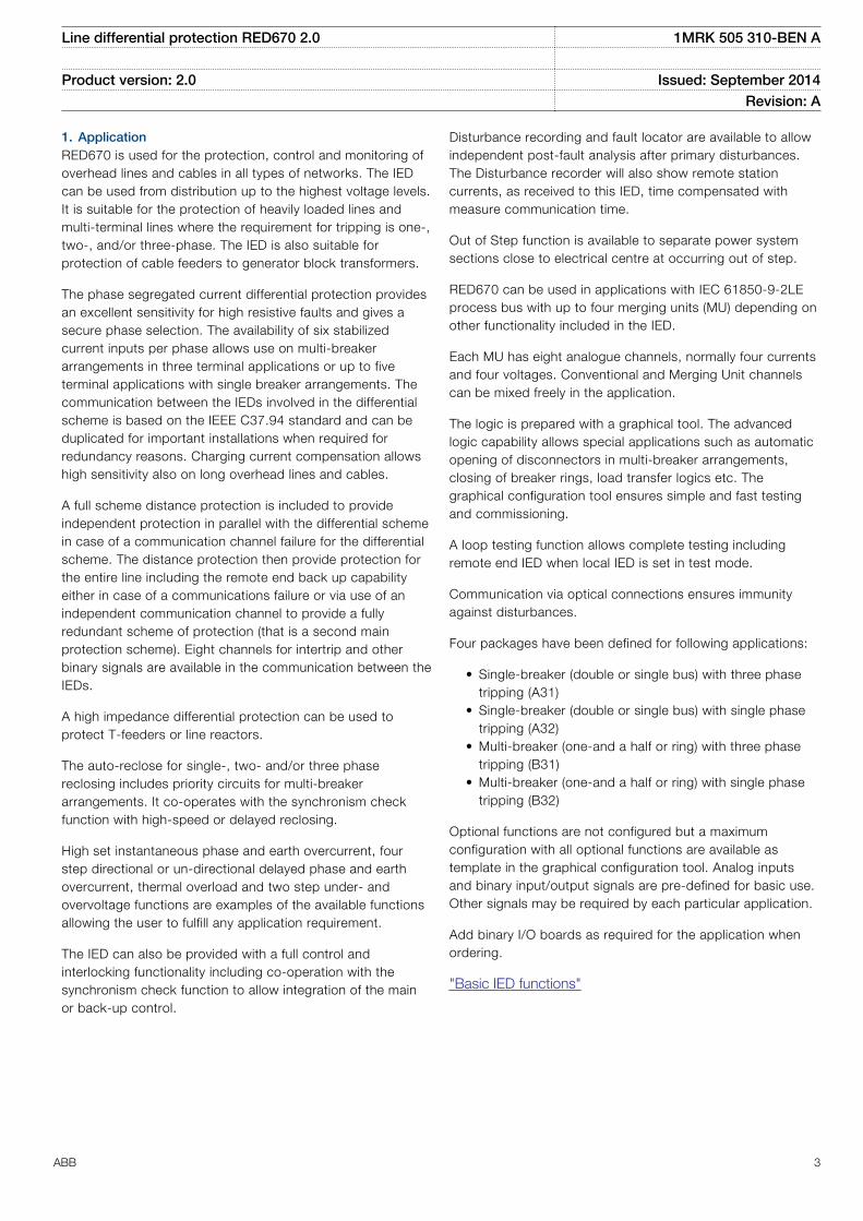
1. ApplicationRED670 is used for the protection, control and monitoring ofoverhead lines and cables in all types of networks. The IEDcan be used from distribution up to the highest voltage levels.It is suitable for the protection of heavily loaded lines andmulti-terminal lines where the requirement for tripping is one-,two-, and/or three-phase. The IED is also suitable forprotection of cable feeders to generator block transformers.
The phase segregated current differential protection providesan excellent sensitivity for high resistive faults and gives asecure phase selection. The availability of six stabilizedcurrent inputs per phase allows use on multi-breakerarrangements in three terminal applications or up to fiveterminal applications with single breaker arrangements. Thecommunication between the IEDs involved in the differentialscheme is based on the IEEE C37.94 standard and can beduplicated for important installations when required forredundancy reasons. Charging current compensation allowshigh sensitivity also on long overhead lines and cables.
A full scheme distance protection is included to provideindependent protection in parallel with the differential schemein case of a communication channel failure for the differentialscheme. The distance protection then provide protection forthe entire line including the remote end back up capabilityeither in case of a communications failure or via use of anindependent communication channel to provide a fullyredundant scheme of protection (that is a second mainprotection scheme). Eight channels for intertrip and otherbinary signals are available in the communication between theIEDs.
A high impedance differential protection can be used toprotect T-feeders or line reactors.
The auto-reclose for single-, two- and/or three phasereclosing includes priority circuits for multi-breakerarrangements. It co-operates with the synchronism checkfunction with high-speed or delayed reclosing.
High set instantaneous phase and earth overcurrent, fourstep directional or un-directional delayed phase and earthovercurrent, thermal overload and two step under- andovervoltage functions are examples of the available functionsallowing the user to fulfill any application requirement.
The IED can also be provided with a full control andinterlocking functionality including co-operation with thesynchronism check function to allow integration of the mainor back-up control.
Disturbance recording and fault locator are available to allowindependent post-fault analysis after primary disturbances.The Disturbance recorder will also show remote stationcurrents, as received to this IED, time compensated withmeasure communication time.
Out of Step function is available to separate power systemsections close to electrical centre at occurring out of step.
RED670 can be used in applications with IEC 61850-9-2LEprocess bus with up to four merging units (MU) depending onother functionality included in the IED.
Each MU has eight analogue channels, normally four currentsand four voltages. Conventional and Merging Unit channelscan be mixed freely in the application.
The logic is prepared with a graphical tool. The advancedlogic capability allows special applications such as automaticopening of disconnectors in multi-breaker arrangements,closing of breaker rings, load transfer logics etc. Thegraphical configuration tool ensures simple and fast testingand commissioning.
A loop testing function allows complete testing includingremote end IED when local IED is set in test mode.
Communication via optical connections ensures immunityagainst disturbances.
Four packages have been defined for following applications:
• Single-breaker (double or single bus) with three phasetripping (A31)
• Single-breaker (double or single bus) with single phasetripping (A32)
• Multi-breaker (one-and a half or ring) with three phasetripping (B31)
• Multi-breaker (one-and a half or ring) with single phasetripping (B32)
Optional functions are not configured but a maximumconfiguration with all optional functions are available astemplate in the graphical configuration tool. Analog inputsand binary input/output signals are pre-defined for basic use.Other signals may be required by each particular application.
Add binary I/O boards as required for the application whenordering.
"Basic IED functions"
Line differential protection RED670 2.0 1MRK 505 310-BEN A
Product version: 2.0 Issued: September 2014Revision: A
ABB 3
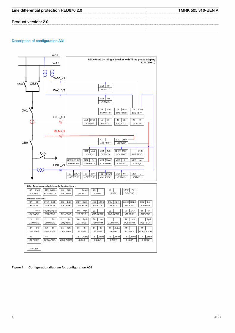
Description of configuration A31
QB1 QB2
QA1
QB9
QC9
WA1
WA2
RED670 A31 – Single Breaker with Three phase tripping
12AI (6I+6U)
LOV PTUV
27 3U<
CV MMXN
MET P/Q
ETP MMTR
MET W/Varh
V MMXU
MET U
LC PTTR
26 θ>
C MMXU
MET I
UV2 PTUV
27 2(3U<)
C MSQI
MET Isqi
BRC PTOC
46 Iub>
DRP RDRE
DFR/SER DR
OV2 PTOV
59 2(3U>)
VN MMXU
MET UN
V MSQI
MET Usqi
OC4 PTOC
51_67 4(3I>)
CC RBRF
50BF 3I>BF
PH PIOC
50 3I>>
LMB RFLO
21FL FL
L3C PDIF
87L 3Id/I>
REM CT
WA2_VT
Other Functions available from the function library
VD SPVC
60 Ud>
FDPS PDIS
21
NS4 PTOC
46I2 4(I2>)
CV GAPC
2(I>/U<)
ZCV PSOF
Optional Functions
VDC PTOV
60 Ud>
Q CBAY
Control
ROV2 PTOV
59N 2(U0>)
CCS SPVC
87 INd/I
FMPS PDIS
21
EF PIOC
50N IN>>
GOP PDOP
32 P>
HZ PDIF
87 Id>
L6C PDIF
87L 3Id/I>
STB PTOC
50STB 3I>STB
S SIMG
63
LT3C PDIF
87LT 3Id/I>
LT6C PDIS
87LT 3Id/I>
SA PTOF
81 f>
SA PTUF
81 f<
GUP PDUP
37 P<
ZMM PDIS
21 Z<
ZMH PDIS
21 Z<
ZMQ PDIS
21 Z<
ZM RPSB
68 Zpsb
PSP PPAM
78 Ucos
ZSM GAPC
OEX PVPH
24 U/f>
ZC PSCH
85
ZCRW PSCH
85
ZCLC PSCH S CILO
3 Control
VN MMXU
MET UN
VN MMXU
MET UN
SMB RREC
79 0→1
SMP PTRC
94 1→0 25 SC/VC
SES RSYN
FUF SPVC
U>/I<
LDL PSCH
87L
WA1_VT
LINE_CT
S SIML
71
CC PDSC
52PD PD
SDEPSDE
67N IN>
EF4 PTOC
51N_67N 4(IN>)
ZMF PDIS
21 Z<
ZD RDIR
21 Z<_>
PSL PSCH
Zpsl
OOS PPAM
78 Ucos
SA PFRC
81 df/dt<>
ECRW PSCH
85
EC PSCH
85
S CSWI
3 Control
S XSWI
3 Control
Q CRSV
3 Control
S XCBR
3 Control
S SCBR
LINE_VT
IEC05000842 V3 EN
Figure 1. Configuration diagram for configuration A31
Line differential protection RED670 2.0 1MRK 505 310-BEN A
Product version: 2.0
4 ABB
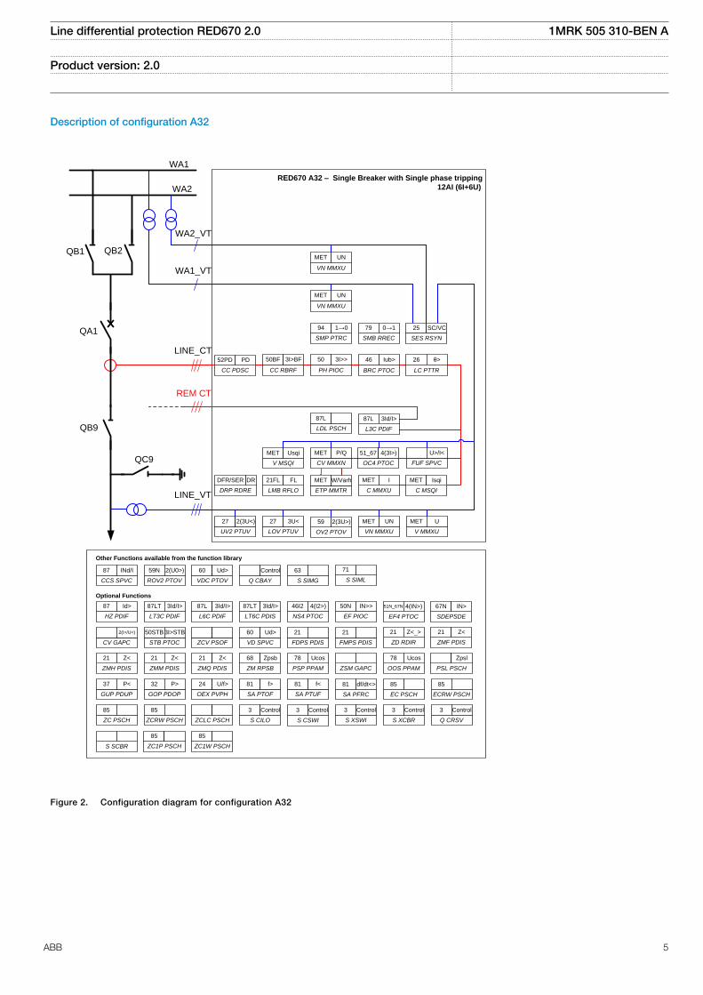
Description of configuration A32
QB1 QB2
QA1
QB9
QC9
WA1
WA2
RED670 A32 – Single Breaker with Single phase tripping
12AI (6I+6U)
LOV PTUV
27 3U<
CV MMXN
MET P/Q
ETP MMTR
MET W/Varh
V MMXU
MET U
LC PTTR
26 θ>
C MMXU
MET I
UV2 PTUV
27 2(3U<)
C MSQI
MET Isqi
BRC PTOC
46 Iub>
DRP RDRE
DFR/SER DR
OV2 PTOV
59 2(3U>)
VN MMXU
MET UN
V MSQI
MET Usqi
OC4 PTOC
51_67 4(3I>)
CC RBRF
50BF 3I>BF
PH PIOC
50 3I>>
LMB RFLO
21FL FL
L3C PDIF
87L 3Id/I>
REM CT
WA2_VT
Other Functions available from the function library
VD SPVC
60 Ud>
FDPS PDIS
21
NS4 PTOC
46I2 4(I2>)
CV GAPC
2(I>/U<)
ZCV PSOF
Optional Functions
VDC PTOV
60 Ud>
Q CBAY
Control
ROV2 PTOV
59N 2(U0>)
CCS SPVC
87 INd/I
FMPS PDIS
21
EF PIOC
50N IN>>
GOP PDOP
32 P>
HZ PDIF
87 Id>
L6C PDIF
87L 3Id/I>
STB PTOC
50STB 3I>STB
S SIMG
63
LT3C PDIF
87LT 3Id/I>
LT6C PDIS
87LT 3Id/I>
SA PTOF
81 f>
SA PTUF
81 f<
GUP PDUP
37 P<
ZMM PDIS
21 Z<
ZMH PDIS
21 Z<
ZMQ PDIS
21 Z<
ZM RPSB
68 Zpsb
PSP PPAM
78 Ucos
ZSM GAPC
OEX PVPH
24 U/f>
ZC PSCH
85
ZCRW PSCH
85
ZCLC PSCH S CILO
3 Control
VN MMXU
MET UN
VN MMXU
MET UN
SMB RREC
79 0→1
SMP PTRC
94 1→0 25 SC/VC
SES RSYN
FUF SPVC
U>/I<
LDL PSCH
87L
WA1_VT
LINE_CT
S SIML
71
CC PDSC
52PD PD
SDEPSDE
67N IN>
EF4 PTOC
51N_67N 4(IN>)
ZMF PDIS
21 Z<
ZD RDIR
21 Z<_>
PSL PSCH
Zpsl
OOS PPAM
78 Ucos
SA PFRC
81 df/dt<>
ECRW PSCH
85
EC PSCH
85
S CSWI
3 Control
S XSWI
3 Control
Q CRSV
3 Control
S XCBR
3 Control
S SCBR
LINE_VT
ZC1P PSCH
85
ZC1W PSCH
85
IEC05000840 V3 EN
Figure 2. Configuration diagram for configuration A32
Line differential protection RED670 2.0 1MRK 505 310-BEN A
Product version: 2.0
ABB 5
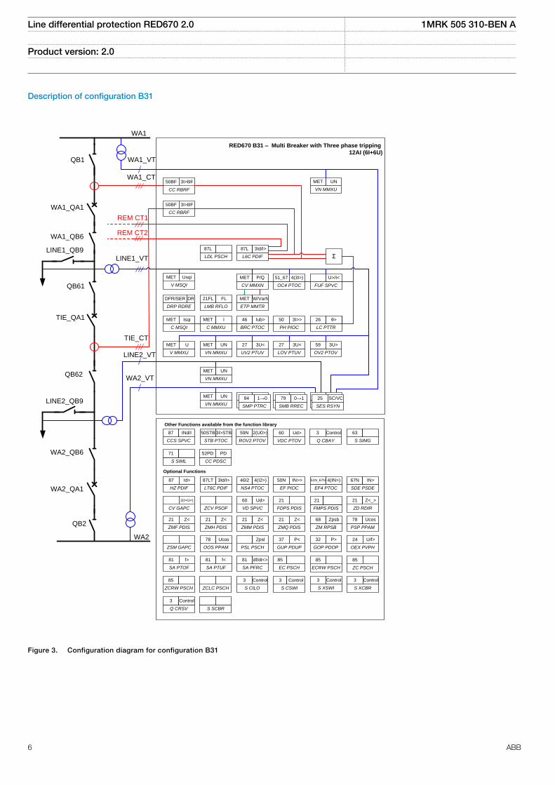
Description of configuration B31
QB1
WA1_QB6
QB61
QB62
LINE2_QB9
WA2_QB6
WA1_QA1
TIE_QA1
RED670 B31 – Multi Breaker with Three phase tripping
12AI (6I+6U)
CC RBRF
50BF 3I>BF
VN MMXU
MET UN
LDL PSCH
87L
ETP MMTR
MET W/Varh
CV MMXN
MET P/Q
QB2
WA2_QA1
UV2 PTUV
27 3U<
OC4 PTOC
51_67 4(3I>)
OV2 PTOV
59 3U>
LOV PTUV
27 3U<
V MMXU
MET U
C MSQI
MET Isqi
DRP RDRE
DFR/SER DR
V MSQI
MET Usqi
SMB RREC
79 0→1
SMP PTRC
94 1→0
SES RSYN
25 SC
SMB RREC
79 0→1
SMP PTRC
94 1→0
SES RSYN
25 SC/VC
FUF SPVC
U>/I<
LC PTTR
26 3I>STBθ>
C MMXU
MET I
BRC PTOC
46 Iub>
PH PIOC
50 3I>>
ΣL6C PDIF
87L 3Id/I>
REM CT1
REM CT2
CC RBRF
50BF 3I>BF
LINE1_QB9
S SIMG
63
Other Functions available from the function library
Optional Functions
ROV2 PTOV
59N 2(U0>)
VDC PTOV
60 Ud>
STB PTOC
50STB 3I>STB
CCS SPVC
87 INd/I
Q CBAY
3 Control
FDPS PDIS
21
FMPS PDIS
21
EF4 PTOC
51N_67N 4(IN>)
CV GAPC
2(I>/U<)
VD SPVC
60 Ud>
ZD RDIR
21 Z<_>
SDE PSDE
67N IN>
ZMH PDIS
21 Z<
HZ PDIF
87 Id>
NS4 PTOC
46I2 4(I2>)
ZSM GAPC
ZCV PSOF
OOS PPAM
78 Ucos
PSL PSCH
Zpsl
GUP PDUP
37 P<
LT6C PDIF
87LT 3Id/I>
EF PIOC
50N IN>>
ZMQ PDIS
21 Z<
ZM RPSB
68 Zpsb
ZMF PDIS
21 Z<
PSP PPAM
78 Ucos
ZMM PDIS
21 Z<
SA PFRC
81 df/dt<>
EC PSCH
85
SA PTUF
81 f<
SA PTOF
81 f>
OEX PVPH
24 U/f>
GOP PDOP
32 P>
S CILO
3 Control
S CSWI
3 Control
ZCLC PSCHZCRW PSCH
85
S SCBRQ CRSV
3 Control
ZC PSCH
85
ECRW PSCH
85
S XCBR
3 Control
S XSWI
3 Control
S SIML
71
CC PDSC
52PD PD
VN MMXU
MET UN
VN MMXU
MET UN
VN MMXU
MET UN
LMB RFLO
21FL FL
WA1
WA1_VT
WA1_CT
LINE1_VT
TIE_CT
LINE2_VT
WA2_VT
WA2
IEC05000843 V3 EN
Figure 3. Configuration diagram for configuration B31
Line differential protection RED670 2.0 1MRK 505 310-BEN A
Product version: 2.0
6 ABB
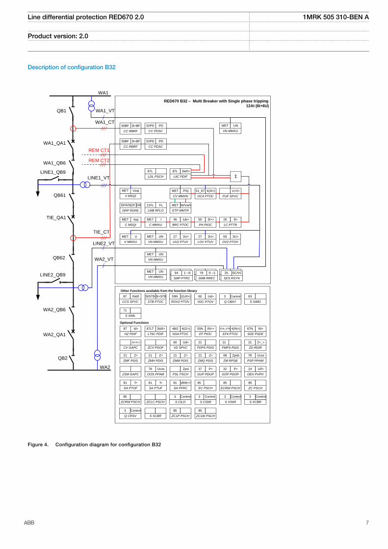
Description of configuration B32
QB1
WA1_QB6
QB61
QB62
LINE2_QB9
WA2_QB6
WA1_QA1
TIE_QA1
RED670 B32 – Multi Breaker with Single phase tripping
12AI (6I+6U)
CC RBRF
50BF 3I>BF
VN MMXU
MET UN
LDL PSCH
87L
ETP MMTR
MET W/Varh
CV MMXN
MET P/Q
QB2
WA2_QA1
UV2 PTUV
27 3U<
OC4 PTOC
51_67 4(3I>)
OV2 PTOV
59 3U>
LOV PTUV
27 3U<
V MMXU
MET U
C MSQI
MET Isqi
DRP RDRE
DFR/SER DR
V MSQI
MET Usqi
SMB RREC
79 0→1
SMP PTRC
94 1→0
SES RSYN
25 SC
SMB RREC
79 0→1
SMP PTRC
94 1→0
SES RSYN
25 SC/VC
FUF SPVC
U>/I<
LC PTTR
26 3I>STBθ>
C MMXU
MET I
BRC PTOC
46 Iub>
PH PIOC
50 3I>>
ΣL6C PDIF
87L 3Id/I>
REM CT1
REM CT2
CC RBRF
50BF 3I>BF
LINE1_QB9
S SIMG
63
Other Functions available from the function library
Optional Functions
ROV2 PTOV
59N 2(U0>)
VDC PTOV
60 Ud>
STB PTOC
50STB 3I>STB
CCS SPVC
87 INd/I
Q CBAY
3 Control
FDPS PDIS
21
FMPS PDIS
21
EF4 PTOC
51N_67N 4(IN>)
CV GAPC
2(I>/U<)
VD SPVC
60 Ud>
ZD RDIR
21 Z<_>
SDE PSDE
67N IN>
ZMH PDIS
21 Z<
HZ PDIF
87 Id>
NS4 PTOC
46I2 4(I2>)
ZSM GAPC
ZCV PSOF
OOS PPAM
78 Ucos
PSL PSCH
Zpsl
GUP PDUP
37 P<
LT6C PDIF
87LT 3Id/I>
EF PIOC
50N IN>>
ZMQ PDIS
21 Z<
ZM RPSB
68 Zpsb
ZMF PDIS
21 Z<
PSP PPAM
78 Ucos
ZMM PDIS
21 Z<
SA PFRC
81 df/dt<>
EC PSCH
85
SA PTUF
81 f<
SA PTOF
81 f>
OEX PVPH
24 U/f>
GOP PDOP
32 P>
S CILO
3 Control
S CSWI
3 Control
ZCLC PSCHZCRW PSCH
85
S SCBRQ CRSV
3 Control
ZC PSCH
85
ECRW PSCH
85
S XCBR
3 Control
S XSWI
3 Control
S SIML
71
VN MMXU
MET UN
VN MMXU
MET UN
VN MMXU
MET UN
LMB RFLO
21FL FL
WA1
WA1_VT
WA1_CT
LINE1_VT
TIE_CT
LINE2_VT
WA2_VT
WA2
CC PDSC
52PD PD
CC PDSC
52PD PD
ZC1W PSCH
85
ZC1P PSCH
85
IEC05000841 V3 EN
Figure 4. Configuration diagram for configuration B32
Line differential protection RED670 2.0 1MRK 505 310-BEN A
Product version: 2.0
ABB 7

2. Available functions
Main protection functions
2 = number of basic instances0-3 = option quantities3-A03 = optional function included in packages A03 (refer to ordering details)
Line differential protection RED670 2.0 1MRK 505 310-BEN A
Product version: 2.0
8 ABB
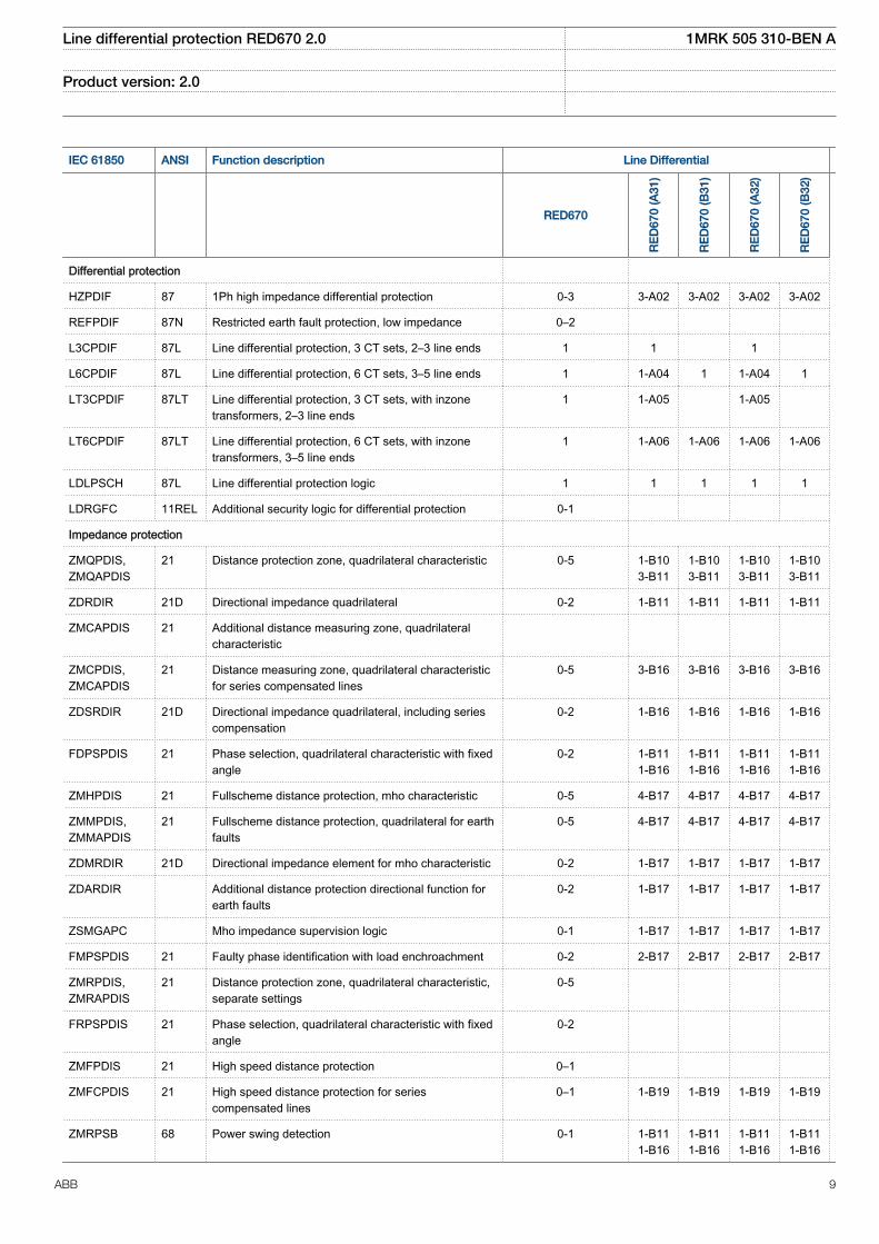
IEC 61850 ANSI Function description Line Differential
RED670
RE
D67
0 (A
31)
RE
D67
0 (B
31)
RE
D67
0 (A
32)
RE
D67
0 (B
32)
Differential protection
HZPDIF 87 1Ph high impedance differential protection 0-3 3-A02 3-A02 3-A02 3-A02
REFPDIF 87N Restricted earth fault protection, low impedance 0–2
L3CPDIF 87L Line differential protection, 3 CT sets, 2–3 line ends 1 1 1
L6CPDIF 87L Line differential protection, 6 CT sets, 3–5 line ends 1 1-A04 1 1-A04 1
LT3CPDIF 87LT Line differential protection, 3 CT sets, with inzonetransformers, 2–3 line ends
1 1-A05 1-A05
LT6CPDIF 87LT Line differential protection, 6 CT sets, with inzonetransformers, 3–5 line ends
1 1-A06 1-A06 1-A06 1-A06
LDLPSCH 87L Line differential protection logic 1 1 1 1 1
LDRGFC 11REL Additional security logic for differential protection 0-1
Impedance protection
ZMQPDIS,ZMQAPDIS
21 Distance protection zone, quadrilateral characteristic 0-5 1-B103-B11
1-B103-B11
1-B103-B11
1-B103-B11
ZDRDIR 21D Directional impedance quadrilateral 0-2 1-B11 1-B11 1-B11 1-B11
ZMCAPDIS 21 Additional distance measuring zone, quadrilateralcharacteristic
ZMCPDIS,ZMCAPDIS
21 Distance measuring zone, quadrilateral characteristicfor series compensated lines
0-5 3-B16 3-B16 3-B16 3-B16
ZDSRDIR 21D Directional impedance quadrilateral, including seriescompensation
0-2 1-B16 1-B16 1-B16 1-B16
FDPSPDIS 21 Phase selection, quadrilateral characteristic with fixedangle
0-2 1-B111-B16
1-B111-B16
1-B111-B16
1-B111-B16
ZMHPDIS 21 Fullscheme distance protection, mho characteristic 0-5 4-B17 4-B17 4-B17 4-B17
ZMMPDIS,ZMMAPDIS
21 Fullscheme distance protection, quadrilateral for earthfaults
0-5 4-B17 4-B17 4-B17 4-B17
ZDMRDIR 21D Directional impedance element for mho characteristic 0-2 1-B17 1-B17 1-B17 1-B17
ZDARDIR Additional distance protection directional function forearth faults
0-2 1-B17 1-B17 1-B17 1-B17
ZSMGAPC Mho impedance supervision logic 0-1 1-B17 1-B17 1-B17 1-B17
FMPSPDIS 21 Faulty phase identification with load enchroachment 0-2 2-B17 2-B17 2-B17 2-B17
ZMRPDIS,ZMRAPDIS
21 Distance protection zone, quadrilateral characteristic,separate settings
0-5
FRPSPDIS 21 Phase selection, quadrilateral characteristic with fixedangle
0-2
ZMFPDIS 21 High speed distance protection 0–1
ZMFCPDIS 21 High speed distance protection for seriescompensated lines
0–1 1-B19 1-B19 1-B19 1-B19
ZMRPSB 68 Power swing detection 0-1 1-B111-B16
1-B111-B16
1-B111-B16
1-B111-B16
Line differential protection RED670 2.0 1MRK 505 310-BEN A
Product version: 2.0
ABB 9
IEC 61850 ANSI Function description Line Differential
RED670
RE
D67
0 (A
31)
RE
D67
0 (B
31)
RE
D67
0 (A
32)
RE
D67
0 (B
32)
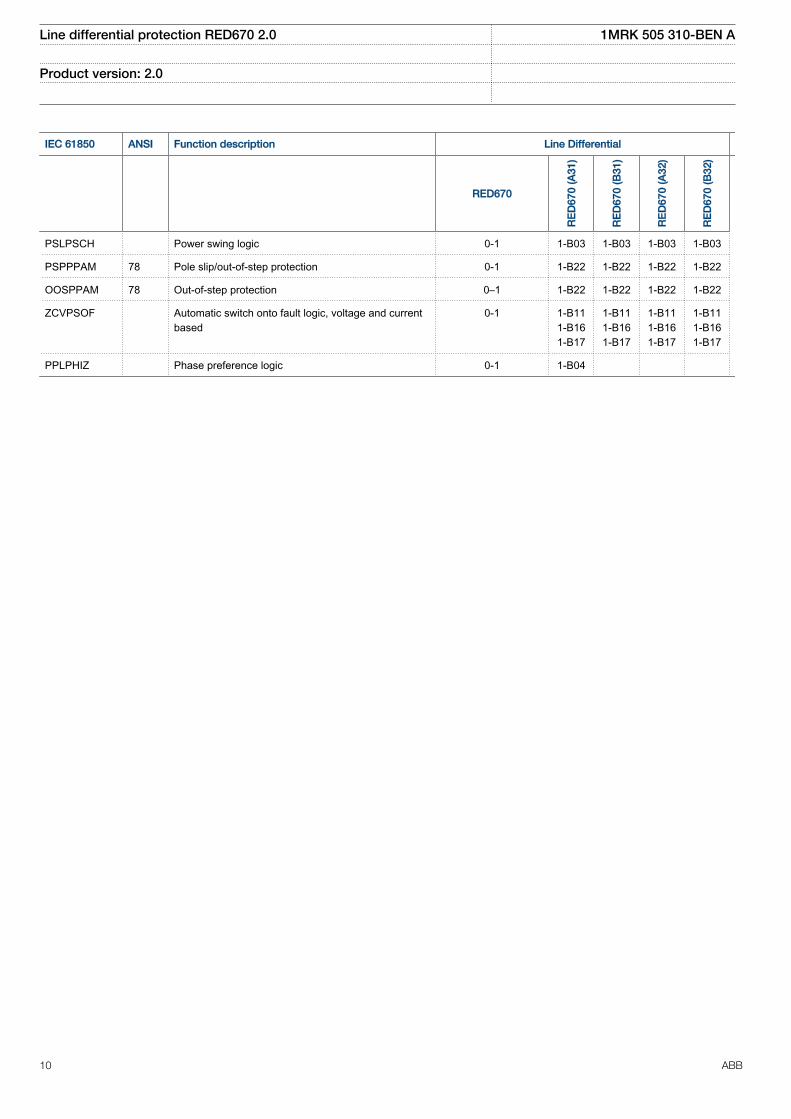
PSLPSCH Power swing logic 0-1 1-B03 1-B03 1-B03 1-B03
PSPPPAM 78 Pole slip/out-of-step protection 0-1 1-B22 1-B22 1-B22 1-B22
OOSPPAM 78 Out-of-step protection 0–1 1-B22 1-B22 1-B22 1-B22
ZCVPSOF Automatic switch onto fault logic, voltage and currentbased
0-1 1-B111-B161-B17
1-B111-B161-B17
1-B111-B161-B17
1-B111-B161-B17
PPLPHIZ Phase preference logic 0-1 1-B04
Line differential protection RED670 2.0 1MRK 505 310-BEN A
Product version: 2.0
10 ABB
Back-up protection functions
IEC 61850 ANSI Function description Line Differential
RED670
RE
D67
0 (A
31)
RE
D67
0 (B
31)
RE
D67
0 (A
32)
RE
D67
0 (B
32)
Current protection
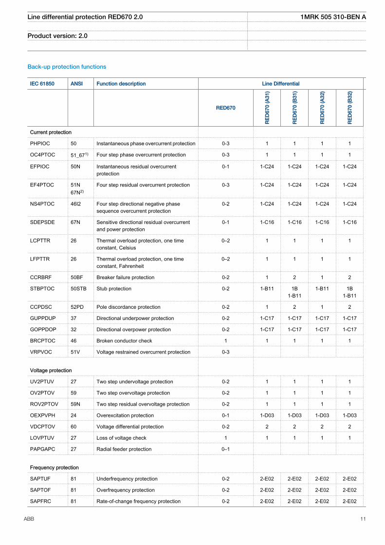
PHPIOC 50 Instantaneous phase overcurrent protection 0-3 1 1 1 1
OC4PTOC 51_671) Four step phase overcurrent protection 0-3 1 1 1 1
EFPIOC 50N Instantaneous residual overcurrentprotection
0-1 1-C24 1-C24 1-C24 1-C24
EF4PTOC 51N67N2)
Four step residual overcurrent protection 0-3 1-C24 1-C24 1-C24 1-C24
NS4PTOC 46I2 Four step directional negative phasesequence overcurrent protection
0-2 1-C24 1-C24 1-C24 1-C24
SDEPSDE 67N Sensitive directional residual overcurrentand power protection
0-1 1-C16 1-C16 1-C16 1-C16
LCPTTR 26 Thermal overload protection, one timeconstant, Celsius
0–2 1 1 1 1
LFPTTR 26 Thermal overload protection, one timeconstant, Fahrenheit
0–2 1 1 1 1
CCRBRF 50BF Breaker failure protection 0-2 1 2 1 2
STBPTOC 50STB Stub protection 0-2 1-B11 1B1-B11
1-B11 1B1-B11
CCPDSC 52PD Pole discordance protection 0-2 1 2 1 2
GUPPDUP 37 Directional underpower protection 0-2 1-C17 1-C17 1-C17 1-C17
GOPPDOP 32 Directional overpower protection 0-2 1-C17 1-C17 1-C17 1-C17
BRCPTOC 46 Broken conductor check 1 1 1 1 1
VRPVOC 51V Voltage restrained overcurrent protection 0-3
Voltage protection
UV2PTUV 27 Two step undervoltage protection 0-2 1 1 1 1
OV2PTOV 59 Two step overvoltage protection 0-2 1 1 1 1
ROV2PTOV 59N Two step residual overvoltage protection 0-2 1 1 1 1
OEXPVPH 24 Overexcitation protection 0-1 1-D03 1-D03 1-D03 1-D03
VDCPTOV 60 Voltage differential protection 0-2 2 2 2 2
LOVPTUV 27 Loss of voltage check 1 1 1 1 1
PAPGAPC 27 Radial feeder protection 0–1
Frequency protection
SAPTUF 81 Underfrequency protection 0-2 2-E02 2-E02 2-E02 2-E02
SAPTOF 81 Overfrequency protection 0-2 2-E02 2-E02 2-E02 2-E02
SAPFRC 81 Rate-of-change frequency protection 0-2 2-E02 2-E02 2-E02 2-E02
Line differential protection RED670 2.0 1MRK 505 310-BEN A
Product version: 2.0
ABB 11
IEC 61850 ANSI Function description Line Differential
RED670
RE
D67
0 (A
31)
RE
D67
0 (B
31)
RE
D67
0 (A
32)
RE
D67
0 (B
32)
Multipurpose protection
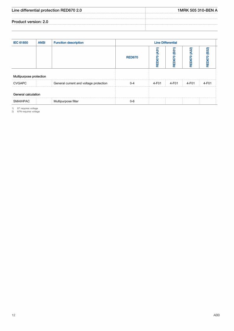
CVGAPC General current and voltage protection 0-4 4-F01 4-F01 4-F01 4-F01
General calculation
SMAIHPAC Multipurpose filter 0-6
1) 67 requires voltage2) 67N requires voltage
Line differential protection RED670 2.0 1MRK 505 310-BEN A
Product version: 2.0
12 ABB
Control and monitoring functions
IEC 61850 ANSI Function description Line Differential
RED670
RE
D67
0 (A
31)
RE
D67
0 (B
31)
RE
D67
0 (A
32)
RE
D67
0 (B
32)
Control
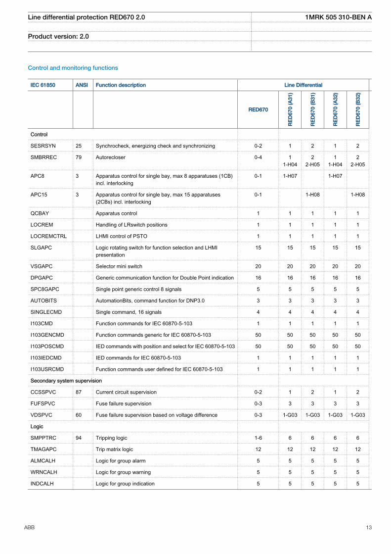
SESRSYN 25 Synchrocheck, energizing check and synchronizing 0-2 1 2 1 2
SMBRREC 79 Autorecloser 0-4 11-H04
22-H05
11-H04
22-H05
APC8 3 Apparatus control for single bay, max 8 apparatuses (1CB)incl. interlocking
0-1 1-H07 1-H07
APC15 3 Apparatus control for single bay, max 15 apparatuses(2CBs) incl. interlocking
0-1 1-H08 1-H08
QCBAY Apparatus control 1 1 1 1 1
LOCREM Handling of LRswitch positions 1 1 1 1 1
LOCREMCTRL LHMI control of PSTO 1 1 1 1 1
SLGAPC Logic rotating switch for function selection and LHMIpresentation
15 15 15 15 15
VSGAPC Selector mini switch 20 20 20 20 20
DPGAPC Generic communication function for Double Point indication 16 16 16 16 16
SPC8GAPC Single point generic control 8 signals 5 5 5 5 5
AUTOBITS AutomationBits, command function for DNP3.0 3 3 3 3 3
SINGLECMD Single command, 16 signals 4 4 4 4 4
I103CMD Function commands for IEC 60870-5-103 1 1 1 1 1
I103GENCMD Function commands generic for IEC 60870-5-103 50 50 50 50 50
I103POSCMD IED commands with position and select for IEC 60870-5-103 50 50 50 50 50
I103IEDCMD IED commands for IEC 60870-5-103 1 1 1 1 1
I103USRCMD Function commands user defined for IEC 60870-5-103 1 1 1 1 1
Secondary system supervision
CCSSPVC 87 Current circuit supervision 0-2 1 2 1 2
FUFSPVC Fuse failure supervision 0-3 3 3 3 3
VDSPVC 60 Fuse failure supervision based on voltage difference 0-3 1-G03 1-G03 1-G03 1-G03
Logic
SMPPTRC 94 Tripping logic 1-6 6 6 6 6
TMAGAPC Trip matrix logic 12 12 12 12 12
ALMCALH Logic for group alarm 5 5 5 5 5
WRNCALH Logic for group warning 5 5 5 5 5
INDCALH Logic for group indication 5 5 5 5 5
Line differential protection RED670 2.0 1MRK 505 310-BEN A
Product version: 2.0
ABB 13
IEC 61850 ANSI Function description Line Differential
RED670
RE
D67
0 (A
31)
RE
D67
0 (B
31)
RE
D67
0 (A
32)
RE
D67
0 (B
32)
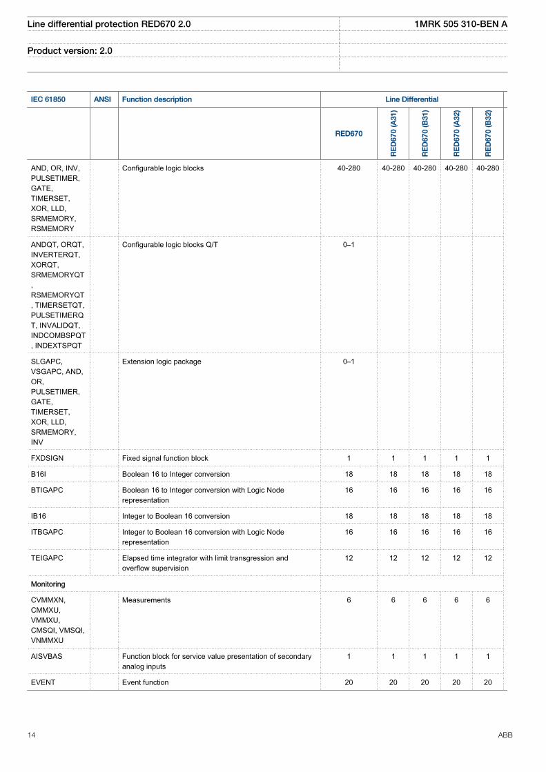
AND, OR, INV,PULSETIMER,GATE,TIMERSET,XOR, LLD,SRMEMORY,RSMEMORY
Configurable logic blocks 40-280 40-280 40-280 40-280 40-280
ANDQT, ORQT,INVERTERQT,XORQT,SRMEMORYQT,RSMEMORYQT, TIMERSETQT,PULSETIMERQT, INVALIDQT,INDCOMBSPQT, INDEXTSPQT
Configurable logic blocks Q/T 0–1
SLGAPC,VSGAPC, AND,OR,PULSETIMER,GATE,TIMERSET,XOR, LLD,SRMEMORY,INV
Extension logic package 0–1
FXDSIGN Fixed signal function block 1 1 1 1 1
B16I Boolean 16 to Integer conversion 18 18 18 18 18
BTIGAPC Boolean 16 to Integer conversion with Logic Noderepresentation
16 16 16 16 16
IB16 Integer to Boolean 16 conversion 18 18 18 18 18
ITBGAPC Integer to Boolean 16 conversion with Logic Noderepresentation
16 16 16 16 16
TEIGAPC Elapsed time integrator with limit transgression andoverflow supervision
12 12 12 12 12
Monitoring
CVMMXN,CMMXU,VMMXU,CMSQI, VMSQI,VNMMXU
Measurements 6 6 6 6 6
AISVBAS Function block for service value presentation of secondaryanalog inputs
1 1 1 1 1
EVENT Event function 20 20 20 20 20
Line differential protection RED670 2.0 1MRK 505 310-BEN A
Product version: 2.0
14 ABB
IEC 61850 ANSI Function description Line Differential
RED670
RE
D67
0 (A
31)
RE
D67
0 (B
31)
RE
D67
0 (A
32)
RE
D67
0 (B
32)
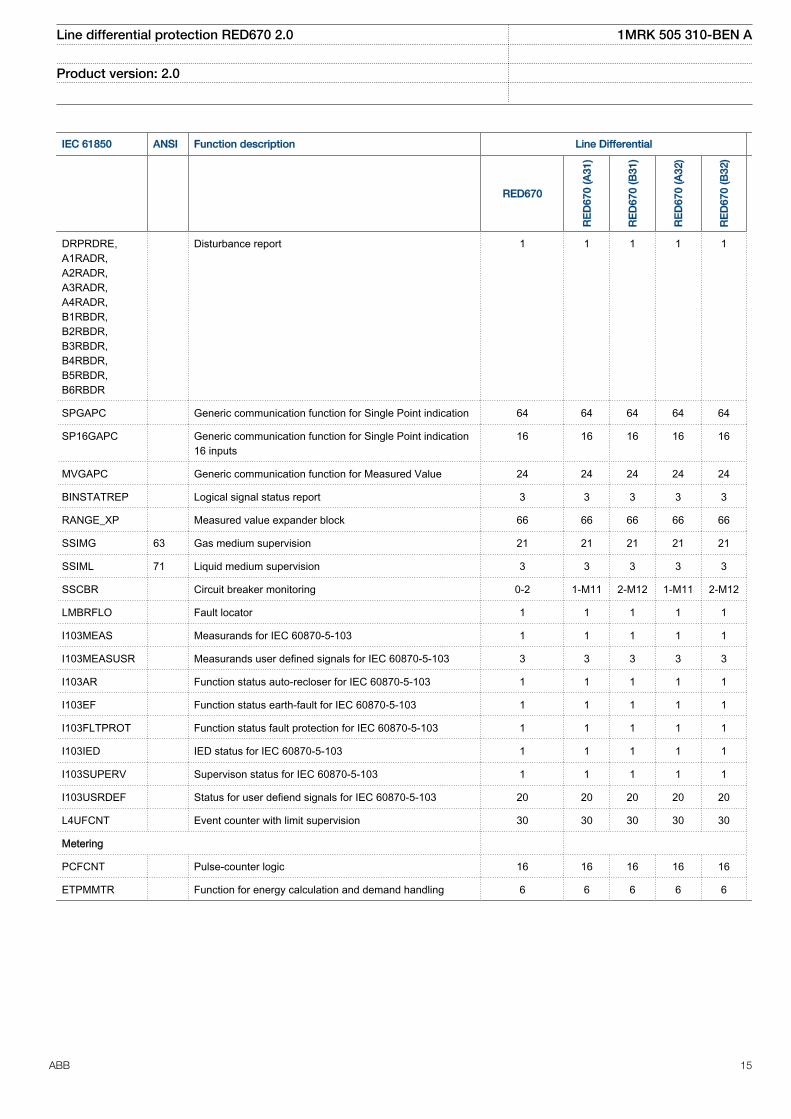
DRPRDRE,A1RADR,A2RADR,A3RADR,A4RADR,B1RBDR,B2RBDR,B3RBDR,B4RBDR,B5RBDR,B6RBDR
Disturbance report 1 1 1 1 1
SPGAPC Generic communication function for Single Point indication 64 64 64 64 64
SP16GAPC Generic communication function for Single Point indication16 inputs
16 16 16 16 16
MVGAPC Generic communication function for Measured Value 24 24 24 24 24
BINSTATREP Logical signal status report 3 3 3 3 3
RANGE_XP Measured value expander block 66 66 66 66 66
SSIMG 63 Gas medium supervision 21 21 21 21 21
SSIML 71 Liquid medium supervision 3 3 3 3 3
SSCBR Circuit breaker monitoring 0-2 1-M11 2-M12 1-M11 2-M12
LMBRFLO Fault locator 1 1 1 1 1
I103MEAS Measurands for IEC 60870-5-103 1 1 1 1 1
I103MEASUSR Measurands user defined signals for IEC 60870-5-103 3 3 3 3 3
I103AR Function status auto-recloser for IEC 60870-5-103 1 1 1 1 1
I103EF Function status earth-fault for IEC 60870-5-103 1 1 1 1 1
I103FLTPROT Function status fault protection for IEC 60870-5-103 1 1 1 1 1
I103IED IED status for IEC 60870-5-103 1 1 1 1 1
I103SUPERV Supervison status for IEC 60870-5-103 1 1 1 1 1
I103USRDEF Status for user defiend signals for IEC 60870-5-103 20 20 20 20 20
L4UFCNT Event counter with limit supervision 30 30 30 30 30
Metering
PCFCNT Pulse-counter logic 16 16 16 16 16
ETPMMTR Function for energy calculation and demand handling 6 6 6 6 6
Line differential protection RED670 2.0 1MRK 505 310-BEN A
Product version: 2.0
ABB 15
Communication
IEC 61850 ANSI Function description Line Differential
RED670
RE
D67
0 (A
31)
RE
D67
0 (B
31)
RE
D67
0 (A
32)
RE
D67
0 (B
32)
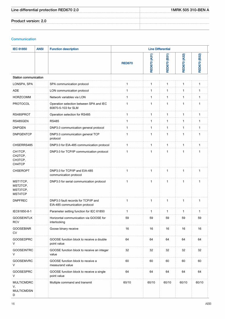
Station communication
LONSPA, SPA SPA communication protocol 1 1 1 1 1
ADE LON communication protocol 1 1 1 1 1
HORZCOMM Network variables via LON 1 1 1 1 1
PROTOCOL Operation selection between SPA and IEC60870-5-103 for SLM
1 1 1 1 1
RS485PROT Operation selection for RS485 1 1 1 1 1
RS485GEN RS485 1 1 1 1 1
DNPGEN DNP3.0 communication general protocol 1 1 1 1 1
DNPGENTCP DNP3.0 communication general TCPprotocol
1 1 1 1 1
CHSERRS485 DNP3.0 for EIA-485 communication protocol 1 1 1 1 1
CH1TCP,CH2TCP,CH3TCP,CH4TCP
DNP3.0 for TCP/IP communication protocol 1 1 1 1 1
CHSEROPT DNP3.0 for TCP/IP and EIA-485communication protocol
1 1 1 1 1
MST1TCP,MST2TCP,MST3TCP,MST4TCP
DNP3.0 for serial communication protocol 1 1 1 1 1
DNPFREC DNP3.0 fault records for TCP/IP andEIA-485 communication protocol
1 1 1 1 1
IEC61850-8-1 Parameter setting function for IEC 61850 1 1 1 1 1
GOOSEINTLKRCV
Horizontal communication via GOOSE forinterlocking
59 59 59 59 59
GOOSEBINRCV
Goose binary receive 16 16 16 16 16
GOOSEDPRCV
GOOSE function block to receive a doublepoint value
64 64 64 64 64
GOOSEINTRCV
GOOSE function block to receive an integervalue
32 32 32 32 32
GOOSEMVRCV
GOOSE function block to receive ameasurand value
60 60 60 60 60
GOOSESPRCV
GOOSE function block to receive a singlepoint value
64 64 64 64 64
MULTICMDRCV,MULTICMDSND
Multiple command and transmit 60/10 60/10 60/10 60/10 60/10
Line differential protection RED670 2.0 1MRK 505 310-BEN A
Product version: 2.0
16 ABB
IEC 61850 ANSI Function description Line Differential
RED670
RE
D67
0 (A
31)
RE
D67
0 (B
31)
RE
D67
0 (A
32)
RE
D67
0 (B
32)
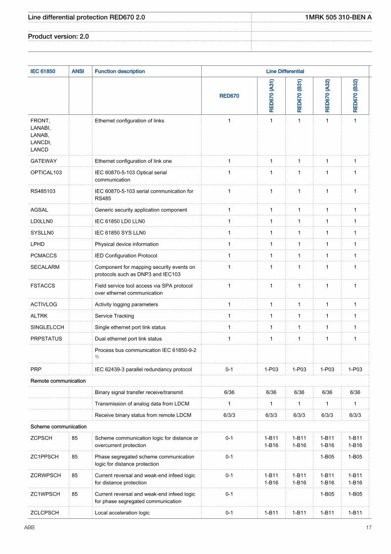
FRONT,LANABI,LANAB,LANCDI,LANCD
Ethernet configuration of links 1 1 1 1 1
GATEWAY Ethernet configuration of link one 1 1 1 1 1
OPTICAL103 IEC 60870-5-103 Optical serialcommunication
1 1 1 1 1
RS485103 IEC 60870-5-103 serial communication forRS485
1 1 1 1 1
AGSAL Generic security application component 1 1 1 1 1
LD0LLN0 IEC 61850 LD0 LLN0 1 1 1 1 1
SYSLLN0 IEC 61850 SYS LLN0 1 1 1 1 1
LPHD Physical device information 1 1 1 1 1
PCMACCS IED Configuration Protocol 1 1 1 1 1
SECALARM Component for mapping security events onprotocols such as DNP3 and IEC103
1 1 1 1 1
FSTACCS Field service tool access via SPA protocolover ethernet communication
1 1 1 1 1
ACTIVLOG Activity logging parameters 1 1 1 1 1
ALTRK Service Tracking 1 1 1 1 1
SINGLELCCH Single ethernet port link status 1 1 1 1 1
PRPSTATUS Dual ethernet port link status 1 1 1 1 1
Process bus communication IEC 61850-9-21)
PRP IEC 62439-3 parallel redundancy protocol 0-1 1-P03 1-P03 1-P03 1-P03
Remote communication
Binary signal transfer receive/transmit 6/36 6/36 6/36 6/36 6/36
Transmission of analog data from LDCM 1 1 1 1 1
Receive binary status from remote LDCM 6/3/3 6/3/3 6/3/3 6/3/3 6/3/3
Scheme communication
ZCPSCH 85 Scheme communication logic for distance orovercurrent protection
0-1 1-B111-B16
1-B111-B16
1-B111-B16
1-B111-B16
ZC1PPSCH 85 Phase segregated scheme communicationlogic for distance protection
0-1 1-B05 1-B05
ZCRWPSCH 85 Current reversal and weak-end infeed logicfor distance protection
0-1 1-B111-B16
1-B111-B16
1-B111-B16
1-B111-B16
ZC1WPSCH 85 Current reversal and weak-end infeed logicfor phase segregated communication
0-1 1-B05 1-B05
ZCLCPSCH Local acceleration logic 0-1 1-B11 1-B11 1-B11 1-B11
Line differential protection RED670 2.0 1MRK 505 310-BEN A
Product version: 2.0
ABB 17
IEC 61850 ANSI Function description Line Differential
RED670
RE
D67
0 (A
31)
RE
D67
0 (B
31)
RE
D67
0 (A
32)
RE
D67
0 (B
32)
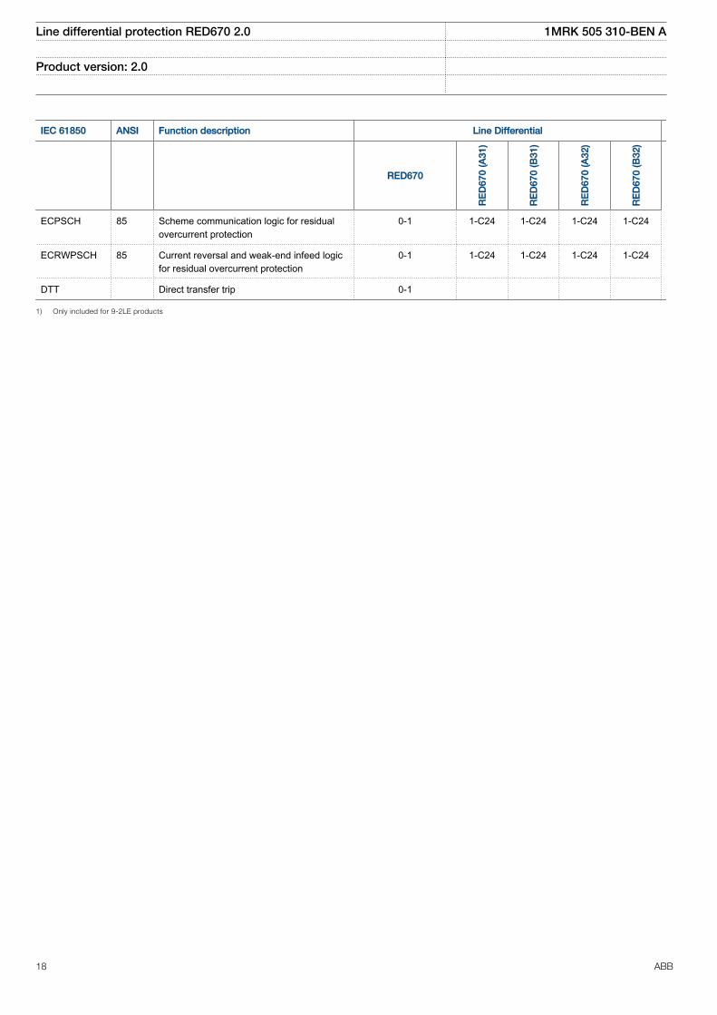
ECPSCH 85 Scheme communication logic for residualovercurrent protection
0-1 1-C24 1-C24 1-C24 1-C24
ECRWPSCH 85 Current reversal and weak-end infeed logicfor residual overcurrent protection
0-1 1-C24 1-C24 1-C24 1-C24
DTT Direct transfer trip 0-1
1) Only included for 9-2LE products
Line differential protection RED670 2.0 1MRK 505 310-BEN A
Product version: 2.0
18 ABB
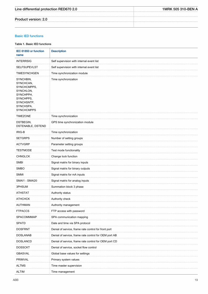
Basic IED functions
Table 1. Basic IED functions
IEC 61850 or functionname
Description
INTERRSIG Self supervision with internal event list
SELFSUPEVLST Self supervision with internal event list
TIMESYNCHGEN Time synchronization module
SYNCHBIN,SYNCHCAN,SYNCHCMPPS,SYNCHLON,SYNCHPPH,SYNCHPPS,SYNCHSNTP,SYNCHSPA,SYNCHCMPPS
Time synchronization
TIMEZONE Time synchronization
DSTBEGIN,DSTENABLE, DSTEND
GPS time synchronization module
IRIG-B Time synchronization
SETGRPS Number of setting groups
ACTVGRP Parameter setting groups
TESTMODE Test mode functionality
CHNGLCK Change lock function
SMBI Signal matrix for binary inputs
SMBO Signal matrix for binary outputs
SMMI Signal matrix for mA inputs
SMAI1 - SMAI20 Signal matrix for analog inputs
3PHSUM Summation block 3 phase
ATHSTAT Authority status
ATHCHCK Authority check
AUTHMAN Authority management
FTPACCS FTP access with password
SPACOMMMAP SPA communication mapping
SPATD Date and time via SPA protocol
DOSFRNT Denial of service, frame rate control for front port
DOSLANAB Denial of service, frame rate control for OEM port AB
DOSLANCD Denial of service, frame rate control for OEM port CD
DOSSCKT Denial of service, socket flow control
GBASVAL Global base values for settings
PRIMVAL Primary system values
ALTMS Time master supervision
ALTIM Time management
Line differential protection RED670 2.0 1MRK 505 310-BEN A
Product version: 2.0
ABB 19
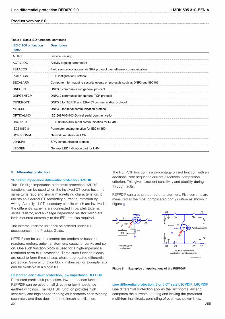
Table 1. Basic IED functions, continued
IEC 61850 or functionname
Description
ALTRK Service tracking
ACTIVLOG Activity logging parameters
FSTACCS Field service tool access via SPA protocol over ethernet communication
PCMACCS IED Configuration Protocol
SECALARM Component for mapping security events on protocols such as DNP3 and IEC103
DNPGEN DNP3.0 communication general protocol
DNPGENTCP DNP3.0 communication general TCP protocol
CHSEROPT DNP3.0 for TCP/IP and EIA-485 communication protocol
MSTSER DNP3.0 for serial communication protocol
OPTICAL103 IEC 60870-5-103 Optical serial communication
RS485103 IEC 60870-5-103 serial communication for RS485
IEC61850-8-1 Parameter setting function for IEC 61850
HORZCOMM Network variables via LON
LONSPA SPA communication protocol
LEDGEN General LED indication part for LHMI
3. Differential protection
1Ph High impedance differential protection HZPDIFThe 1Ph High impedance differential protection HZPDIFfunctions can be used when the involved CT cores have thesame turns ratio and similar magnetizing characteristics. Itutilizes an external CT secondary current summation bywiring. Actually all CT secondary circuits which are involved inthe differential scheme are connected in parallel. Externalseries resistor, and a voltage dependent resistor which areboth mounted externally to the IED, are also required.
The external resistor unit shall be ordered under IEDaccessories in the Product Guide.
HZPDIF can be used to protect tee-feeders or busbars,reactors, motors, auto-transformers, capacitor banks and soon. One such function block is used for a high-impedancerestricted earth fault protection. Three such function blocksare used to form three-phase, phase-segregated differentialprotection. Several function block instances (for example, six)can be available in a single IED.
Restricted earth-fault protection, low impedance REFPDIFRestricted earth-fault protection, low-impedance functionREFPDIF can be used on all directly or low-impedanceearthed windings. The REFPDIF function provides highsensitivity and high speed tripping as it protects each windingseparately and thus does not need inrush stabilization.
The REFPDIF function is a percentage biased function with anadditional zero sequence current directional comparisoncriterion. This gives excellent sensitivity and stability duringthrough faults.
REFPDIF can also protect autotransformers. Five currents aremeasured at the most complicated configuration as shown inFigure 5.
The most typicalapplication
YNdx
dCB
CT
CT
CB Y
IED
CB CB
CB CB
Autotransformer
The most complicatedapplication - autotransformer
CT CT
CT CT
IEC05000058-2-en.vsd
IEC05000058-2 V1 EN
Figure 5. Examples of applications of the REFPDIF
Line differential protection, 3 or 6 CT sets L3CPDIF, L6CPDIFLine differential protection applies the Kirchhoff's law andcompares the currents entering and leaving the protectedmulti-terminal circuit, consisting of overhead power lines,
Line differential protection RED670 2.0 1MRK 505 310-BEN A
Product version: 2.0
20 ABB
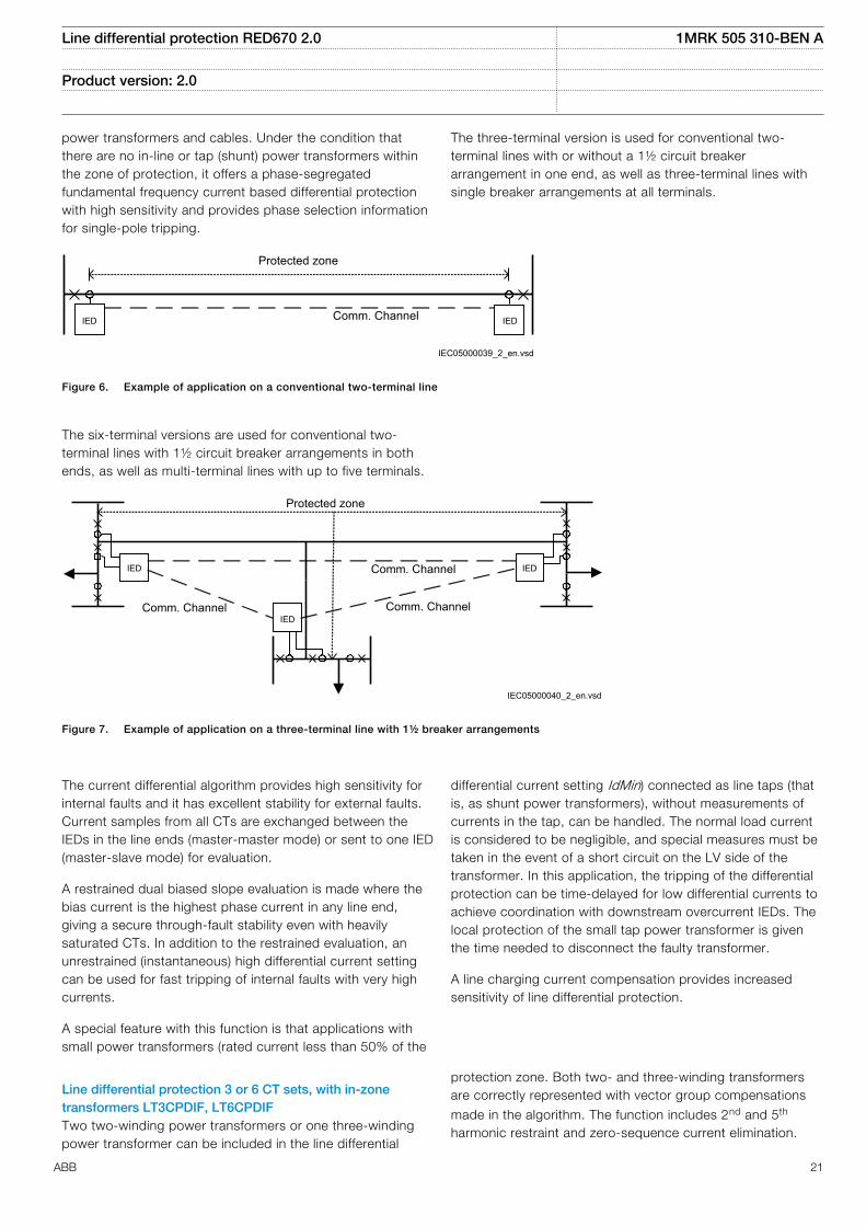
power transformers and cables. Under the condition thatthere are no in-line or tap (shunt) power transformers withinthe zone of protection, it offers a phase-segregatedfundamental frequency current based differential protectionwith high sensitivity and provides phase selection informationfor single-pole tripping.
The three-terminal version is used for conventional two-terminal lines with or without a 1½ circuit breakerarrangement in one end, as well as three-terminal lines withsingle breaker arrangements at all terminals.
IEC05000039_2_en.vsd
Protected zone
Comm. ChannelIED IED
IEC05000039 V2 EN
Figure 6. Example of application on a conventional two-terminal line
The six-terminal versions are used for conventional two-terminal lines with 1½ circuit breaker arrangements in bothends, as well as multi-terminal lines with up to five terminals.
Protected zone
Comm. Channel
IEC05000040_2_en.vsd
IED
IED
IED
Comm. ChannelComm. Channel
IEC05000040 V2 EN
Figure 7. Example of application on a three-terminal line with 1½ breaker arrangements
The current differential algorithm provides high sensitivity forinternal faults and it has excellent stability for external faults.Current samples from all CTs are exchanged between theIEDs in the line ends (master-master mode) or sent to one IED(master-slave mode) for evaluation.
A restrained dual biased slope evaluation is made where thebias current is the highest phase current in any line end,giving a secure through-fault stability even with heavilysaturated CTs. In addition to the restrained evaluation, anunrestrained (instantaneous) high differential current settingcan be used for fast tripping of internal faults with very highcurrents.
A special feature with this function is that applications withsmall power transformers (rated current less than 50% of the
differential current setting IdMin) connected as line taps (thatis, as shunt power transformers), without measurements ofcurrents in the tap, can be handled. The normal load currentis considered to be negligible, and special measures must betaken in the event of a short circuit on the LV side of thetransformer. In this application, the tripping of the differentialprotection can be time-delayed for low differential currents toachieve coordination with downstream overcurrent IEDs. Thelocal protection of the small tap power transformer is giventhe time needed to disconnect the faulty transformer.
A line charging current compensation provides increasedsensitivity of line differential protection.
Line differential protection 3 or 6 CT sets, with in-zonetransformers LT3CPDIF, LT6CPDIFTwo two-winding power transformers or one three-windingpower transformer can be included in the line differential
protection zone. Both two- and three-winding transformersare correctly represented with vector group compensations
made in the algorithm. The function includes 2nd and 5th
harmonic restraint and zero-sequence current elimination.
Line differential protection RED670 2.0 1MRK 505 310-BEN A
Product version: 2.0
ABB 21
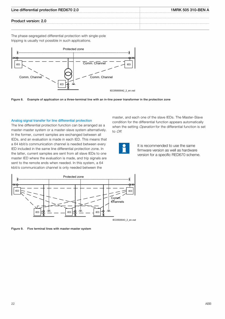
The phase-segregated differential protection with single-poletripping is usually not possible in such applications.
IED
IED IED
Protected zone
Comm. Channel
Comm. Channel
Comm. Channel
IEC05000042_2_en.vsdIEC05000042 V2 EN
Figure 8. Example of application on a three-terminal line with an in-line power transformer in the protection zone
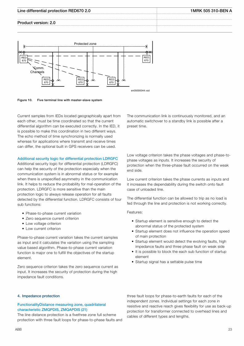
Analog signal transfer for line differential protectionThe line differential protection function can be arranged as amaster-master system or a master-slave system alternatively.In the former, current samples are exchanged between allIEDs, and an evaluation is made in each IED. This means thata 64 kbit/s communication channel is needed between everyIED included in the same line differential protection zone. Inthe latter, current samples are sent from all slave IEDs to onemaster IED where the evaluation is made, and trip signals aresent to the remote ends when needed. In this system, a 64kbit/s communication channel is only needed between the
master, and each one of the slave IEDs. The Master-Slavecondition for the differential function appears automaticallywhen the setting Operation for the differential function is setto Off.
It is recommended to use the samefirmware version as well as hardwareversion for a specific RED670 scheme.
Protected zone
Comm. Channels
IED
IED IED IED
IED
IEC0500043_2_en.vsdIEC05000043 V2 EN
Figure 9. Five terminal lines with master-master system
Line differential protection RED670 2.0 1MRK 505 310-BEN A
Product version: 2.0
22 ABB
RED670
Protected zone
Comm.Channels
RED670
RED670
en05000044.vsd
RED670
RED670
IEC05000044 V1 EN
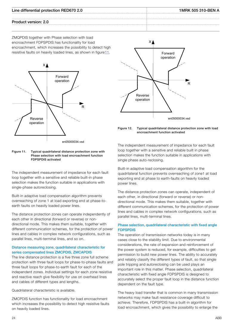
Figure 10. Five terminal line with master-slave system
Current samples from IEDs located geographically apart fromeach other, must be time coordinated so that the currentdifferential algorithm can be executed correctly. In the IED, itis possible to make this coordination in two different ways.The echo method of time synchronizing is normally usedwhereas for applications where transmit and receive timescan differ, the optional built in GPS receivers can be used.
The communication link is continuously monitored, and anautomatic switchover to a standby link is possible after apreset time.
Additional security logic for differential protection LDRGFCAdditional security logic for differential protection (LDRGFC)can help the security of the protection especially when thecommunication system is in abnormal status or for examplewhen there is unspecified asymmetry in the communicationlink. It helps to reduce the probability for mal-operation of theprotection. LDRGFC is more sensitive than the mainprotection logic to always release operation for all faultsdetected by the differential function. LDRGFC consists of foursub functions:
• Phase-to-phase current variation• Zero sequence current criterion• Low voltage criterion• Low current criterion
Phase-to-phase current variation takes the current samplesas input and it calculates the variation using the samplingvalue based algorithm. Phase-to-phase current variationfunction is major one to fulfill the objectives of the startupelement.
Zero sequence criterion takes the zero sequence current asinput. It increases the security of protection during the highimpedance fault conditions.
Low voltage criterion takes the phase voltages and phase-to-phase voltages as inputs. It increases the security ofprotection when the three-phase fault occurred on the weakend side.
Low current criterion takes the phase currents as inputs andit increases the dependability during the switch onto faultcase of unloaded line.
The differential function can be allowed to trip as no load isfed through the line and protection is not working correctly.
Features:
• Startup element is sensitive enough to detect theabnormal status of the protected system
• Startup element does not influence the operation speedof main protection
• Startup element would detect the evolving faults, highimpedance faults and three phase fault on weak side
• It is possible to block the each sub function of startupelement
• Startup signal has a settable pulse time
4. Impedance protection
FunctionalityDistance measuring zone, quadrilateralcharacteristic ZMQPDIS, ZMQAPDIS (21)The line distance protection is a fivethree zone full schemeprotection with three fault loops for phase-to-phase faults and
three fault loops for phase-to-earth faults for each of theindependent zones. Individual settings for each zone inresistive and reactive reach gives flexibility for use as back-upprotection for transformer connected to overhead lines andcables of different types and lengths.
Line differential protection RED670 2.0 1MRK 505 310-BEN A
Product version: 2.0
ABB 23
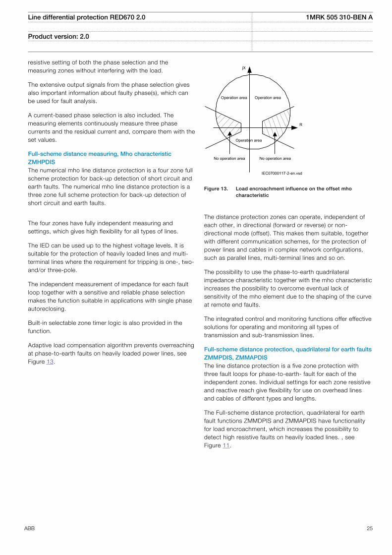
ZMQPDIS together with Phase selection with loadencroachment FDPSPDIS has functionality for loadencroachment, which increases the possibility to detect highresistive faults on heavily loaded lines, as shown in figure11.
en05000034.vsd
R
X
Forwardoperation
Reverseoperation
IEC05000034 V1 EN
Figure 11. Typical quadrilateral distance protection zone withPhase selection with load encroachment functionFDPSPDIS activated
The independent measurement of impedance for each faultloop together with a sensitive and reliable built-in phaseselection makes the function suitable in applications withsingle-phase autoreclosing.
Built-in adaptive load compensation algorithm preventsoverreaching of zone 1 at load exporting end at phase-to-earth faults on heavily loaded power lines.
The distance protection zones can operate independently ofeach other in directional (forward or reverse) or non-directional mode. This makes them suitable, together withdifferent communication schemes, for the protection of powerlines and cables in complex network configurations, such asparallel lines, multi-terminal lines, and so on.
Distance measuring zone, quadrilateral characteristic forseries compensated lines ZMCPDIS, ZMCAPDISThe line distance protection is a five three zone full schemeprotection with three fault loops for phase-to-phase faults andthree fault loops for phase-to-earth fault for each of theindependent zones. Individual settings for each zone resistiveand reactive reach give flexibility for use on overhead linesand cables of different types and lengths.
Quadrilateral characteristic is available.
ZMCPDIS function has functionality for load encroachmentwhich increases the possibility to detect high resistive faultson heavily loaded lines.
en05000034.vsd
R
X
Forwardoperation
Reverseoperation
IEC05000034 V1 EN
Figure 12. Typical quadrilateral distance protection zone with loadencroachment function activated
The independent measurement of impedance for each faultloop together with a sensitive and reliable built in phaseselection makes the function suitable in applications withsingle phase auto-reclosing.
Built-in adaptive load compensation algorithm for thequadrilateral function prevents overreaching of zone1 at loadexporting end at phase to earth-faults on heavily loadedpower lines.
The distance protection zones can operate, independent ofeach other, in directional (forward or reverse) or non-directional mode. This makes them suitable, together withdifferent communication schemes, for the protection of powerlines and cables in complex network configurations, such asparallel lines, multi-terminal lines.
Phase selection, quadrilateral characteristic with fixed angleFDPSPDISThe operation of transmission networks today is in manycases close to the stability limit. Due to environmentalconsiderations, the rate of expansion and reinforcement ofthe power system is reduced, for example, difficulties to getpermission to build new power lines. The ability to accuratelyand reliably classify the different types of fault, so that singlepole tripping and autoreclosing can be used plays animportant role in this matter. Phase selection, quadrilateralcharacteristic with fixed angle FDPSPDIS is designed toaccurately select the proper fault loop in the distance functiondependent on the fault type.
The heavy load transfer that is common in many transmissionnetworks may make fault resistance coverage difficult toachieve. Therefore, FDPSPDIS has a built-in algorithm forload encroachment, which gives the possibility to enlarge the
Line differential protection RED670 2.0 1MRK 505 310-BEN A
Product version: 2.0
24 ABB
resistive setting of both the phase selection and themeasuring zones without interfering with the load.
The extensive output signals from the phase selection givesalso important information about faulty phase(s), which canbe used for fault analysis.
A current-based phase selection is also included. Themeasuring elements continuously measure three phasecurrents and the residual current and, compare them with theset values.
Full-scheme distance measuring, Mho characteristicZMHPDISThe numerical mho line distance protection is a four zone fullscheme protection for back-up detection of short circuit andearth faults. The numerical mho line distance protection is athree zone full scheme protection for back-up detection ofshort circuit and earth faults.
The four zones have fully independent measuring andsettings, which gives high flexibility for all types of lines.
The IED can be used up to the highest voltage levels. It issuitable for the protection of heavily loaded lines and multi-terminal lines where the requirement for tripping is one-, two-and/or three-pole.
The independent measurement of impedance for each faultloop together with a sensitive and reliable phase selectionmakes the function suitable in applications with single phaseautoreclosing.
Built-in selectable zone timer logic is also provided in thefunction.
Adaptive load compensation algorithm prevents overreachingat phase-to-earth faults on heavily loaded power lines, seeFigure 13.
IEC07000117-2-en.vsd
jX
Operation area Operation area
R
Operation area
No operation area No operation area
IEC07000117 V2 EN
Figure 13. Load encroachment influence on the offset mhocharacteristic
The distance protection zones can operate, independent ofeach other, in directional (forward or reverse) or non-directional mode (offset). This makes them suitable, togetherwith different communication schemes, for the protection ofpower lines and cables in complex network configurations,such as parallel lines, multi-terminal lines and so on.
The possibility to use the phase-to-earth quadrilateralimpedance characteristic together with the mho characteristicincreases the possibility to overcome eventual lack ofsensitivity of the mho element due to the shaping of the curveat remote end faults.
The integrated control and monitoring functions offer effectivesolutions for operating and monitoring all types oftransmission and sub-transmission lines.
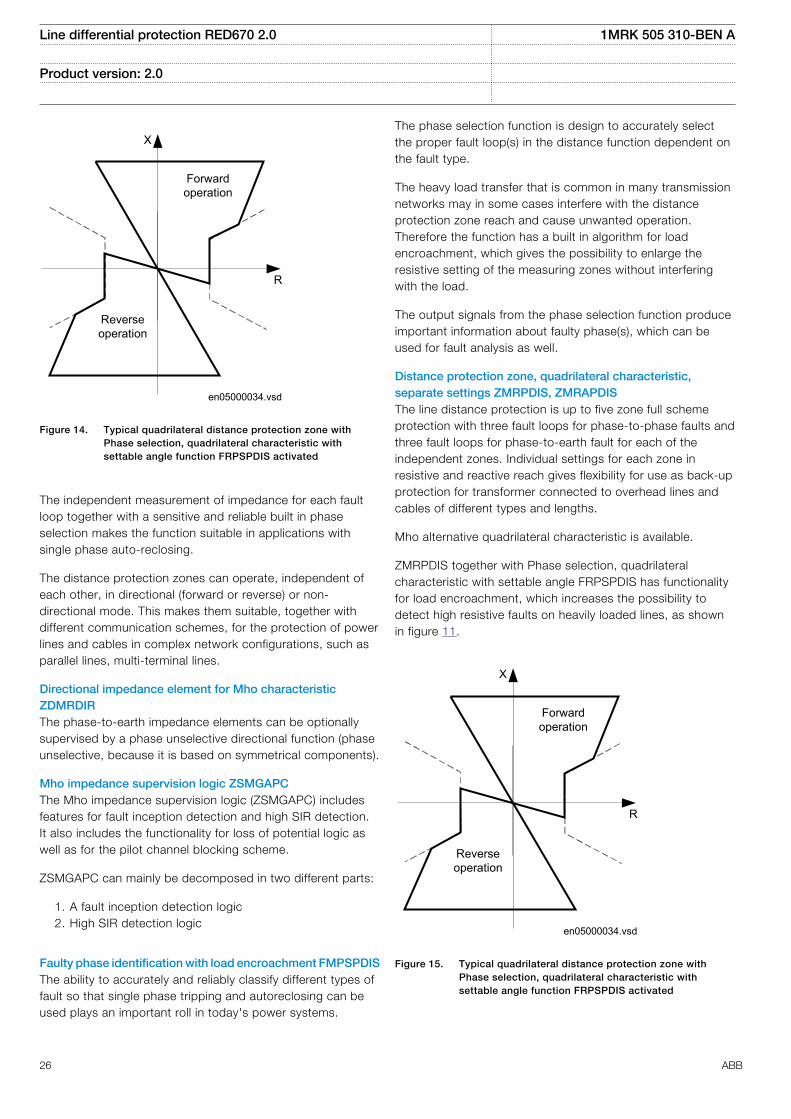
Full-scheme distance protection, quadrilateral for earth faultsZMMPDIS, ZMMAPDISThe line distance protection is a five zone protection withthree fault loops for phase-to-earth- fault for each of theindependent zones. Individual settings for each zone resistiveand reactive reach give flexibility for use on overhead linesand cables of different types and lengths.
The Full-scheme distance protection, quadrilateral for earthfault functions ZMMDPIS and ZMMAPDIS have functionalityfor load encroachment, which increases the possibility todetect high resistive faults on heavily loaded lines. , seeFigure 11.
Line differential protection RED670 2.0 1MRK 505 310-BEN A
Product version: 2.0
ABB 25
en05000034.vsd
R
X
Forwardoperation
Reverseoperation
IEC05000034 V1 EN
Figure 14. Typical quadrilateral distance protection zone withPhase selection, quadrilateral characteristic withsettable angle function FRPSPDIS activated
The independent measurement of impedance for each faultloop together with a sensitive and reliable built in phaseselection makes the function suitable in applications withsingle phase auto-reclosing.
The distance protection zones can operate, independent ofeach other, in directional (forward or reverse) or non-directional mode. This makes them suitable, together withdifferent communication schemes, for the protection of powerlines and cables in complex network configurations, such asparallel lines, multi-terminal lines.
Directional impedance element for Mho characteristicZDMRDIRThe phase-to-earth impedance elements can be optionallysupervised by a phase unselective directional function (phaseunselective, because it is based on symmetrical components).
Mho impedance supervision logic ZSMGAPCThe Mho impedance supervision logic (ZSMGAPC) includesfeatures for fault inception detection and high SIR detection.It also includes the functionality for loss of potential logic aswell as for the pilot channel blocking scheme.
ZSMGAPC can mainly be decomposed in two different parts:
1. A fault inception detection logic2. High SIR detection logic
Faulty phase identification with load encroachment FMPSPDISThe ability to accurately and reliably classify different types offault so that single phase tripping and autoreclosing can beused plays an important roll in today's power systems.
The phase selection function is design to accurately selectthe proper fault loop(s) in the distance function dependent onthe fault type.
The heavy load transfer that is common in many transmissionnetworks may in some cases interfere with the distanceprotection zone reach and cause unwanted operation.Therefore the function has a built in algorithm for loadencroachment, which gives the possibility to enlarge theresistive setting of the measuring zones without interferingwith the load.
The output signals from the phase selection function produceimportant information about faulty phase(s), which can beused for fault analysis as well.
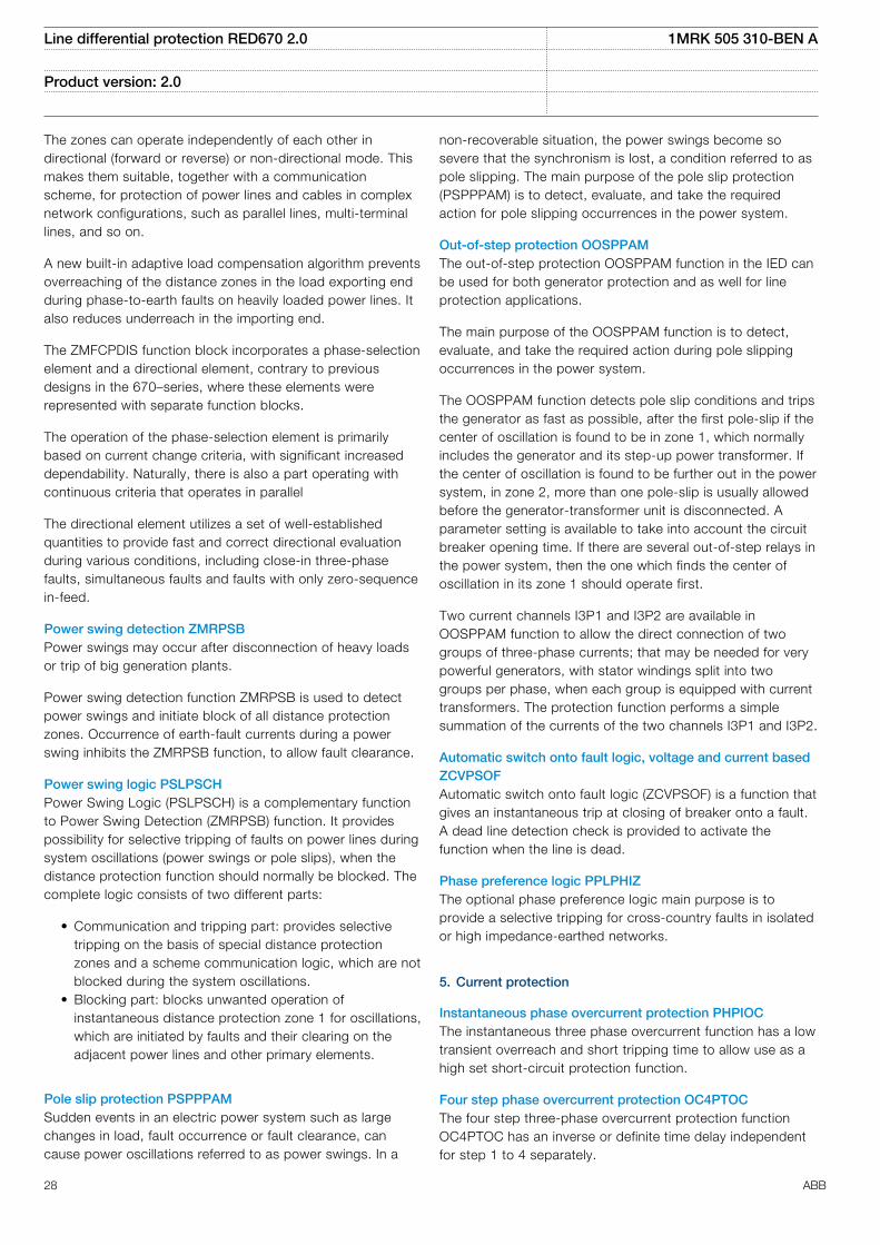
Distance protection zone, quadrilateral characteristic,separate settings ZMRPDIS, ZMRAPDISThe line distance protection is up to five zone full schemeprotection with three fault loops for phase-to-phase faults andthree fault loops for phase-to-earth fault for each of theindependent zones. Individual settings for each zone inresistive and reactive reach gives flexibility for use as back-upprotection for transformer connected to overhead lines andcables of different types and lengths.
Mho alternative quadrilateral characteristic is available.
ZMRPDIS together with Phase selection, quadrilateralcharacteristic with settable angle FRPSPDIS has functionalityfor load encroachment, which increases the possibility todetect high resistive faults on heavily loaded lines, as shownin figure 11.
en05000034.vsd
R
X
Forwardoperation
Reverseoperation
IEC05000034 V1 EN
Figure 15. Typical quadrilateral distance protection zone withPhase selection, quadrilateral characteristic withsettable angle function FRPSPDIS activated
Line differential protection RED670 2.0 1MRK 505 310-BEN A
Product version: 2.0
26 ABB

The independent measurement of impedance for each faultloop together with a sensitive and reliable built-in phaseselection makes the function suitable in applications withsingle pole tripping and autoreclosing.
Built-in adaptive load compensation algorithm preventsoverreaching of zone 1 at load exporting end at phase-to-earth faults on heavily loaded power lines.
The distance protection zones can operate, independent ofeach other, in directional (forward or reverse) or non-directional mode. This makes them suitable, together withdifferent communication schemes, for the protection of powerlines and cables in complex network configurations, such asparallel lines, multi-terminal lines and so on.
Phase selection, quadrilateral characteristic with settableangle FRPSPDISThe operation of transmission networks today is in manycases close to the stability limit. Due to environmentalconsiderations, the rate of expansion and reinforcement ofthe power system is reduced for example, difficulties to getpermission to build new power lines. The ability to accuratelyand reliably classify the different types of fault, so that singlepole tripping and autoreclosing can be used plays animportant role in this matter. The phase selection function isdesigned to accurately select the proper fault loop in thedistance function dependent on the fault type.
The heavy load transfer that is common in many transmissionnetworks may make fault resistance coverage difficult toachieve. Therefore, the function has a built in algorithm forload encroachment, which gives the possibility to enlarge theresistive setting of both the phase selection and themeasuring zones without interfering with the load.
The extensive output signals from the phase selection givesalso important information about faulty phase(s) which can beused for fault analysis.
A current-based phase selection is also included. Themeasuring elements continuously measure three phasecurrents and the residual current and, compare them with theset values.
Distance zones quad with high speed distance protectionZMFPDISThe High speed distance protection (ZMFPDIS) is providingsub-cycle, down towards half-cycle, operate time for basicfaults within 60% of the line length and up to around SIR 5. Atthe same time, it is specifically designed for extra care duringdifficult conditions in high voltage transmission networks, likefaults on long heavily loaded lines and faults generatingheavily distorted signals. These faults are handled withoutmost security and dependability, although sometimes withreduced operating speed.
The ZMFPDIS function is a six zone full scheme protectionwith three fault loops for phase-to-phase faults and three fault
loops for phase-to-earth faults for each of the independentzones, which makes the function suitable in applications withsingle-phase autoreclosing.
The zones can operate independently of each other indirectional (forward or reverse) or non-directional mode.However, zone1 and zone2 is designed to measure in forwarddirection only, while one zone (ZRV) is designed to measure inthe reverse direction. This makes them suitable, together witha communication scheme, for protection of power lines andcables in complex network configurations, such as parallellines, multi-terminal lines, and so on.
A new built-in adaptive load compensation algorithm preventsoverreaching of the distance zones in the load exporting endduring phase-to-earth faults on heavily loaded power lines. Italso reduces underreach in the importing end.
The ZMFPDIS function-block itself incorporates a phase-selection element and a directional element, contrary toprevious designs in the 670-series, where these elementswere represented with separate function-blocks.
The operation of the phase-selection element is primarilybased on current change criteria (i.e. delta quantities), withsignificantly increased dependability. Naturally, there is also aphase selection criterion operating in parallel which bases itsoperation only on voltage and current phasors.
The directional element utilizes a set of well-establishedquantities to provide fast and correct directional decisionduring various power system operating conditions, includingclose-in three-phase faults, simultaneous faults and faultswith only zero-sequence in-feed.
Distance zones quad with high speed distance for seriescompensated networks ZMFCPDISHigh speed distance protection (ZMFCPDIS) provides sub-cycle, down towards half-cycle, operate time for basic faultswithin 60% of the line length and up to around SIR 5. At thesame time, it is specifically designed for extra care duringdifficult conditions in high voltage transmission networks, likefaults on long heavily loaded lines and faults generatingheavily distorted signals. These faults are handled withoutmost security and dependability, although sometimes withreduced operating speed.
High speed distance protection ZMFCPDIS is fundamentallythe same function as ZMFPDIS but provides more flexibility inzone settings to suit more complex applications, such asseries compensated lines. In operation for seriescompensated networks, the parameters of the directionalfunction are altered to handle voltage reversal.
The ZMFCPDIS function is a six-zone full scheme protectionwith three fault loops for phase-to-phase faults and three faultloops for phase-to-earth faults for each of the independentzones, which makes the function suitable in applications withsingle-phase autoreclosing.
Line differential protection RED670 2.0 1MRK 505 310-BEN A
Product version: 2.0
ABB 27
The zones can operate independently of each other indirectional (forward or reverse) or non-directional mode. Thismakes them suitable, together with a communicationscheme, for protection of power lines and cables in complexnetwork configurations, such as parallel lines, multi-terminallines, and so on.
A new built-in adaptive load compensation algorithm preventsoverreaching of the distance zones in the load exporting endduring phase-to-earth faults on heavily loaded power lines. Italso reduces underreach in the importing end.
The ZMFCPDIS function block incorporates a phase-selectionelement and a directional element, contrary to previousdesigns in the 670–series, where these elements wererepresented with separate function blocks.
The operation of the phase-selection element is primarilybased on current change criteria, with significant increaseddependability. Naturally, there is also a part operating withcontinuous criteria that operates in parallel
The directional element utilizes a set of well-establishedquantities to provide fast and correct directional evaluationduring various conditions, including close-in three-phasefaults, simultaneous faults and faults with only zero-sequencein-feed.
Power swing detection ZMRPSBPower swings may occur after disconnection of heavy loadsor trip of big generation plants.
Power swing detection function ZMRPSB is used to detectpower swings and initiate block of all distance protectionzones. Occurrence of earth-fault currents during a powerswing inhibits the ZMRPSB function, to allow fault clearance.
Power swing logic PSLPSCHPower Swing Logic (PSLPSCH) is a complementary functionto Power Swing Detection (ZMRPSB) function. It providespossibility for selective tripping of faults on power lines duringsystem oscillations (power swings or pole slips), when thedistance protection function should normally be blocked. Thecomplete logic consists of two different parts:
• Communication and tripping part: provides selectivetripping on the basis of special distance protectionzones and a scheme communication logic, which are notblocked during the system oscillations.
• Blocking part: blocks unwanted operation ofinstantaneous distance protection zone 1 for oscillations,which are initiated by faults and their clearing on theadjacent power lines and other primary elements.
Pole slip protection PSPPPAMSudden events in an electric power system such as largechanges in load, fault occurrence or fault clearance, cancause power oscillations referred to as power swings. In a
non-recoverable situation, the power swings become sosevere that the synchronism is lost, a condition referred to aspole slipping. The main purpose of the pole slip protection(PSPPPAM) is to detect, evaluate, and take the requiredaction for pole slipping occurrences in the power system.
Out-of-step protection OOSPPAMThe out-of-step protection OOSPPAM function in the IED canbe used for both generator protection and as well for lineprotection applications.
The main purpose of the OOSPPAM function is to detect,evaluate, and take the required action during pole slippingoccurrences in the power system.
The OOSPPAM function detects pole slip conditions and tripsthe generator as fast as possible, after the first pole-slip if thecenter of oscillation is found to be in zone 1, which normallyincludes the generator and its step-up power transformer. Ifthe center of oscillation is found to be further out in the powersystem, in zone 2, more than one pole-slip is usually allowedbefore the generator-transformer unit is disconnected. Aparameter setting is available to take into account the circuitbreaker opening time. If there are several out-of-step relays inthe power system, then the one which finds the center ofoscillation in its zone 1 should operate first.
Two current channels I3P1 and I3P2 are available inOOSPPAM function to allow the direct connection of twogroups of three-phase currents; that may be needed for verypowerful generators, with stator windings split into twogroups per phase, when each group is equipped with currenttransformers. The protection function performs a simplesummation of the currents of the two channels I3P1 and I3P2.
Automatic switch onto fault logic, voltage and current basedZCVPSOFAutomatic switch onto fault logic (ZCVPSOF) is a function thatgives an instantaneous trip at closing of breaker onto a fault.A dead line detection check is provided to activate thefunction when the line is dead.
Phase preference logic PPLPHIZThe optional phase preference logic main purpose is toprovide a selective tripping for cross-country faults in isolatedor high impedance-earthed networks.
5. Current protection
Instantaneous phase overcurrent protection PHPIOCThe instantaneous three phase overcurrent function has a lowtransient overreach and short tripping time to allow use as ahigh set short-circuit protection function.
Four step phase overcurrent protection OC4PTOCThe four step three-phase overcurrent protection functionOC4PTOC has an inverse or definite time delay independentfor step 1 to 4 separately.
Line differential protection RED670 2.0 1MRK 505 310-BEN A
Product version: 2.0
28 ABB
All IEC and ANSI inverse time characteristics are availabletogether with an optional user defined time characteristic.
The directional function needs voltage as it is voltagepolarized with memory. The function can be set to bedirectional or non-directional independently for each of thesteps.
Second harmonic blocking level can be set for the functionand can be used to block each step individually
Instantaneous residual overcurrent protection EFPIOCThe Instantaneous residual overcurrent protection EFPIOChas a low transient overreach and short tripping times toallow the use for instantaneous earth-fault protection, with thereach limited to less than the typical eighty percent of the lineat minimum source impedance. EFPIOC is configured tomeasure the residual current from the three-phase currentinputs and can be configured to measure the current from aseparate current input.
Four step residual overcurrent protection, zero sequence andnegative sequence direction EF4PTOCThe four step residual overcurrent protection EF4PTOC hasan inverse or definite time delay independent for each step.
All IEC and ANSI time-delayed characteristics are availabletogether with an optional user defined characteristic.
EF4PTOC can be set directional or non-directionalindependently for each of the steps.
IDir, UPol and IPol can be independently selected to be eitherzero sequence or negative sequence.
Second harmonic blocking can be set individually for eachstep.
EF4PTOC can be used as main protection for phase-to-earthfaults.
EF4PTOC can also be used to provide a system back-up forexample, in the case of the primary protection being out ofservice due to communication or voltage transformer circuitfailure.
Directional operation can be combined together withcorresponding communication logic in permissive or blockingteleprotection scheme. Current reversal and weak-end infeedfunctionality are available as well.
Residual current can be calculated by summing the threephase currents or taking the input from neutral CT
Four step negative sequence overcurrent protectionNS4PTOCFour step negative sequence overcurrent protection(NS4PTOC) has an inverse or definite time delay independentfor each step separately.
All IEC and ANSI time delayed characteristics are availabletogether with an optional user defined characteristic.
The directional function is voltage polarized.
NS4PTOC can be set directional or non-directionalindependently for each of the steps.
NS4PTOC can be used as main protection for unsymmetricalfault; phase-phase short circuits, phase-phase-earth shortcircuits and single phase earth faults.
NS4PTOC can also be used to provide a system backup forexample, in the case of the primary protection being out ofservice due to communication or voltage transformer circuitfailure.
Directional operation can be combined together withcorresponding communication logic in permissive or blockingteleprotection scheme. The same logic as for directional zerosequence current can be used. Current reversal and weak-end infeed functionality are available.
Sensitive directional residual overcurrent and powerprotection SDEPSDEIn isolated networks or in networks with high impedanceearthing, the earth fault current is significantly smaller thanthe short circuit currents. In addition to this, the magnitude ofthe fault current is almost independent on the fault location inthe network. The protection can be selected to use either theresidual current or residual power component 3U0·3I0·cos j,for operating quantity with maintained short circuit capacity.There is also available one nondirectional 3I0 step and one3U0 overvoltage tripping step.
No specific sensitive current input is needed. SDEPSDE canbe set as low 0.25% of IBase.
Thermal overload protection, one time constant LCPTTR/LFPTTRThe increasing utilization of the power system closer to thethermal limits has generated a need of a thermal overloadprotection for power lines.
A thermal overload will often not be detected by otherprotection functions and the introduction of the thermaloverload protection can allow the protected circuit to operatecloser to the thermal limits.
The three-phase current measuring protection has an I2tcharacteristic with settable time constant and a thermalmemory. The temperature is displayed in either Celsius orFahrenheit, depending on whether the function used isLCPTTR (Celsius) or LFPTTR (Fahrenheit).
An alarm level gives early warning to allow operators to takeaction well before the line is tripped.
Estimated time to trip before operation, and estimated time toreclose after operation are presented.
Line differential protection RED670 2.0 1MRK 505 310-BEN A
Product version: 2.0
ABB 29
Breaker failure protection CCRBRFBreaker failure protection (CCRBRF) ensures a fast backuptripping of surrounding breakers in case the own breaker failsto open. CCRBRF can be current-based, contact-based or anadaptive combination of these two conditions.
Current check with extremely short reset time is used ascheck criterion to achieve high security against inadvertentoperation.
Contact check criteria can be used where the fault currentthrough the breaker is small.
CCRBRF can be single- or three-phase initiated to allow usewith single phase tripping applications. For the three-phaseversion of CCRBRF the current criteria can be set to operateonly if two out of four for example, two phases or one phaseplus the residual current start. This gives a higher security tothe back-up trip command.
CCRBRF function can be programmed to give a single- orthree-phase re-trip of the own breaker to avoid unnecessarytripping of surrounding breakers at an incorrect initiation dueto mistakes during testing.
Stub protection STBPTOCWhen a power line is taken out of service for maintenanceand the line disconnector is opened in multi-breakerarrangements the voltage transformers will mostly be outsideon the disconnected part. The primary line distanceprotection will thus not be able to operate and must beblocked.
The stub protection STBPTOC covers the zone between thecurrent transformers and the open disconnector. The three-phase instantaneous overcurrent function is released from anormally open, NO (b) auxiliary contact on the linedisconnector.
Pole discordance protection CCPDSCAn open phase can cause negative and zero sequencecurrents which cause thermal stress on rotating machinesand can cause unwanted operation of zero sequence ornegative sequence current functions.
Normally the own breaker is tripped to correct such asituation. If the situation persists the surrounding breakersshould be tripped to clear the unsymmetrical load situation.
The Pole discordance protection function CCPDSC operatesbased on information from auxiliary contacts of the circuitbreaker for the three phases with additional criteria fromunsymmetrical phase currents when required.
Directional over/underpower protection GOPPDOP/GUPPDUPThe directional over-/under-power protection GOPPDOP/GUPPDUP can be used wherever a high/low active, reactiveor apparent power protection or alarming is required. The
functions can alternatively be used to check the direction ofactive or reactive power flow in the power system. There area number of applications where such functionality is needed.Some of them are:
• detection of reversed active power flow• detection of high reactive power flow
Each function has two steps with definite time delay.
Broken conductor check BRCPTOCThe main purpose of the function Broken conductor check(BRCPTOC) is the detection of broken conductors onprotected power lines and cables (series faults). Detectioncan be used to give alarm only or trip the line breaker.
Voltage-restrained time overcurrent protection VRPVOCVoltage-restrained time overcurrent protection (VRPVOC)function can be used as generator backup protection againstshort-circuits.
The overcurrent protection feature has a settable current levelthat can be used either with definite time or inverse timecharacteristic. Additionally, it can be voltage controlled/restrained.
One undervoltage step with definite time characteristic is alsoavailable within the function in order to provide functionalityfor overcurrent protection with undervoltage seal-in.
6. Voltage protection
Two step undervoltage protection UV2PTUVUndervoltages can occur in the power system during faults orabnormal conditions. Two step undervoltage protection(UV2PTUV) function can be used to open circuit breakers toprepare for system restoration at power outages or as long-time delayed back-up to primary protection.
UV2PTUV has two voltage steps, each with inverse or definitetime delay.
UV2PTUV has a high reset ratio to allow settings close tosystem service voltage.
Two step overvoltage protection OV2PTOVOvervoltages may occur in the power system during abnormalconditions such as sudden power loss, tap changerregulating failures, and open line ends on long lines.
OV2PTOV has two voltage steps, each of them with inverseor definite time delayed.
OV2PTOV has a high reset ratio to allow settings close tosystem service voltage.
Two step residual overvoltage protection ROV2PTOVResidual voltages may occur in the power system duringearth faults.
Line differential protection RED670 2.0 1MRK 505 310-BEN A
Product version: 2.0
30 ABB
Two step residual overvoltage protection ROV2PTOV functioncalculates the residual voltage from the three-phase voltageinput transformers or measures it from a single voltage inputtransformer fed from an open delta or neutral point voltagetransformer.
ROV2PTOV has two voltage steps, each with inverse ordefinite time delay.
Reset delay ensures operation for intermittent earth faults.
Overexcitation protection OEXPVPHWhen the laminated core of a power transformer or generatoris subjected to a magnetic flux density beyond its designlimits, stray flux will flow into non-laminated components thatare not designed to carry flux. This will cause eddy currentsto flow. These eddy currents can cause excessive heatingand severe damage to insulation and adjacent parts in arelatively short time. The function has settable inverseoperating curves and independent alarm stages.
Voltage differential protection VDCPTOVA voltage differential monitoring function is available. Itcompares the voltages from two three phase sets of voltagetransformers and has one sensitive alarm step and one tripstep.
Loss of voltage check LOVPTUVLoss of voltage check LOVPTUV is suitable for use innetworks with an automatic system restoration function.LOVPTUV issues a three-pole trip command to the circuitbreaker, if all three phase voltages fall below the set value fora time longer than the set time and the circuit breakerremains closed.
The operation of LOVPTUV is supervised by the fuse failuresupervision FUFSPVC.
Radial feeder protection PAPGAPCThe PAPGAPC function is used to provide protection of radialfeeders having passive loads or weak end in-feed sources. Itis possible to achieve fast tripping using communicationsystem with remote end or delayed tripping not requiringcommunication or upon communication system failure. Forfast tripping, scheme communication is required. Delayedtripping does not require scheme communication.
The PAPGAPC function performs phase selection usingmeasured voltages. Each phase voltage is compared to theopposite phase-phase voltage. A phase is deemed to have afault if its phase voltage drops below a settable percentage ofthe opposite phase-phase voltage. The phase - phasevoltages include memory. This memory function has asettable time constant.
The voltage-based phase selection is used for both fast anddelayed tripping. To achieve fast tripping, schemecommunication is required. Delayed tripping does not requirescheme communication. It is possible to permit delayed
tripping only upon failure of the communications channel byblocking the delayed tripping logic with a communicationschannel healthy input signal.
On receipt of the communications signal, phase selectiveoutputs for fast tripping are set based on the phase(s) inwhich the phase selection function has operated.
For delayed tripping, single pole and three pole delays areseparately and independently settable. Furthermore, it ispossible to enable or disable single pole and three poledelayed tripping. For single phase faults, it is possible toinclude a residual current check in the tripping logic. Threepole tripping is always selected for phase selection on morethan one phase. Three pole tripping will also occur if theresidual current exceeds the set level during fuse failure for atime longer than the three pole trip delay time.
7. Frequency protection
Underfrequency protection SAPTUFUnderfrequency occurs as a result of a lack of generation inthe network.
Underfrequency protection SAPTUF measures frequency withhigh accuracy, and is used for load shedding systems,remedial action schemes, gas turbine startup and so on.Separate definite time delays are provided for operate andrestore.
SAPTUF is provided with undervoltage blocking.
The operation is based on positive sequence voltagemeasurement and requires two phase-phase or three phase-neutral voltages to be connected. For information about howto connect analog inputs, refer to Application manual/IEDapplication/Analog inputs/Setting guidelines
Overfrequency protection SAPTOFOverfrequency protection function SAPTOF is applicable in allsituations, where reliable detection of high fundamental powersystem frequency is needed.
Overfrequency occurs because of sudden load drops orshunt faults in the power network. Close to the generatingplant, generator governor problems can also cause overfrequency.
SAPTOF measures frequency with high accuracy, and is usedmainly for generation shedding and remedial action schemes.It is also used as a frequency stage initiating load restoring. Adefinite time delay is provided for operate.
SAPTOF is provided with an undervoltage blocking.
The operation is based on positive sequence voltagemeasurement and requires two phase-phase or three phase-neutral voltages to be connected. For information about how
Line differential protection RED670 2.0 1MRK 505 310-BEN A
Product version: 2.0
ABB 31
to connect analog inputs, refer to Application manual/IEDapplication/Analog inputs/Setting guidelines
Rate-of-change frequency protection SAPFRCThe rate-of-change frequency protection function SAPFRCgives an early indication of a main disturbance in the system.SAPFRC measures frequency with high accuracy, and can beused for generation shedding, load shedding and remedialaction schemes. SAPFRC can discriminate between apositive or negative change of frequency. A definite time delayis provided for operate.
SAPFRC is provided with an undervoltage blocking. Theoperation is based on positive sequence voltagemeasurement and requires two phase-phase or three phase-neutral voltages to be connected. For information about howto connect analog inputs, refer to Application manual/IEDapplication/Analog inputs/Setting guidelines.
8. Multipurpose protection
General current and voltage protection CVGAPCThe General current and voltage protection (CVGAPC) can beutilized as a negative sequence current protection detectingunsymmetrical conditions such as open phase orunsymmetrical faults.
CVGAPC can also be used to improve phase selection forhigh resistive earth faults, outside the distance protectionreach, for the transmission line. Three functions are used,which measures the neutral current and each of the threephase voltages. This will give an independence from loadcurrents and this phase selection will be used in conjunctionwith the detection of the earth fault from the directional earthfault protection function.
9. Secondary system supervision
Current circuit supervision CCSSPVCOpen or short circuited current transformer cores can causeunwanted operation of many protection functions such asdifferential, earth-fault current and negative-sequence currentfunctions.
It must be remembered that a blocking of protectionfunctions at an occurrence of open CT circuit will mean thatthe situation will remain and extremely high voltages willstress the secondary circuit.
Current circuit supervision (CCSSPVC) compares the residualcurrent from a three phase set of current transformer coreswith the neutral point current on a separate input taken fromanother set of cores on the current transformer.
A detection of a difference indicates a fault in the circuit andis used as alarm or to block protection functions expected togive inadvertent tripping.
Fuse failure supervision FUFSPVCThe aim of the fuse failure supervision function FUFSPVC is toblock voltage measuring functions at failures in the secondarycircuits between the voltage transformer and the IED in orderto avoid inadvertent operations that otherwise might occur.
The fuse failure supervision function basically has threedifferent detection methods, negative sequence and zerosequence based detection and an additional delta voltageand delta current detection.
The negative sequence detection algorithm is recommendedfor IEDs used in isolated or high-impedance earthednetworks. It is based on the negative-sequence quantities.
The zero sequence detection is recommended for IEDs usedin directly or low impedance earthed networks. It is based onthe zero sequence measuring quantities.
The selection of different operation modes is possible by asetting parameter in order to take into account the particularearthing of the network.
A criterion based on delta current and delta voltagemeasurements can be added to the fuse failure supervisionfunction in order to detect a three phase fuse failure, which inpractice is more associated with voltage transformerswitching during station operations.
Fuse failure supervision VDSPVCDifferent protection functions within the protection IEDoperates on the basis of measured voltage at the relay point.Some example of protection functions are:
• Distance protection function.• Undervoltage function.• Energisation function and voltage check for the weak
infeed logic.
These functions can operate unintentionally, if a fault occursin the secondary circuits between voltage instrumenttransformers and the IED. These unintentional operations canbe prevented by VDSPVC.
VDSPVC is designed to detect fuse failures or faults in voltagemeasurement circuit, based on phase wise comparison ofvoltages of main and pilot fused circuits. VDSPVC blockingoutput can be configured to block functions that need to beblocked in case of faults in the voltage circuit.
Multipurpose filter SMAIHPACThe multi-purpose filter function block, SMAIHPAC, isarranged as a three-phase filter. It has very much the sameuser interface (e.g. inputs and outputs) as the standard pre-processing function block SMAI. However the main differenceis that it can be used to extract any frequency componentfrom the input signal. Thus it can, for example, be used tobuild sub-synchronous resonance protection for synchronousgenerator.
Line differential protection RED670 2.0 1MRK 505 310-BEN A
Product version: 2.0
32 ABB
10. Control
Synchrocheck, energizing check, and synchronizing SESRSYNThe Synchronizing function allows closing of asynchronousnetworks at the correct moment including the breaker closingtime, which improves the network stability.
Synchrocheck, energizing check, and synchronizingSESRSYN function checks that the voltages on both sides ofthe circuit breaker are in synchronism, or with at least oneside dead to ensure that closing can be done safely.
SESRSYN function includes a built-in voltage selectionscheme for double bus and 1½ breaker or ring busbararrangements.
Manual closing as well as automatic reclosing can bechecked by the function and can have different settings.
For systems, which are running asynchronous, asynchronizing function is provided. The main purpose of thesynchronizing function is to provide controlled closing ofcircuit breakers when two asynchronous systems are going tobe connected. The synchronizing function evaluates voltagedifference, phase angle difference, slip frequency andfrequency rate of change before issuing a controlled closingof the circuit breaker. Breaker closing time is a parametersetting.
Autorecloser SMBRRECThe autorecloser SMBRREC function provides high-speedand/or delayed auto-reclosing for single or multi-breakerapplications.
Up to five three-phase reclosing attempts can be included byparameter setting. The first attempt can be single-, two and/or three phase for single phase or multi-phase faultsrespectively.
Multiple autoreclosing functions are provided for multi-breakerarrangements. A priority circuit allows one circuit breaker toclose first and the second will only close if the fault proved tobe transient.
Each autoreclosing function is configured to co-operate withthe synchrocheck function.
Apparatus control APCThe apparatus control functions are used for control andsupervision of circuit breakers, disconnectors and earthingswitches within a bay. Permission to operate is given afterevaluation of conditions from other functions such asinterlocking, synchrocheck, operator place selection andexternal or internal blockings.
Apparatus control features:• Select-Execute principle to give high reliability• Selection function to prevent simultaneous operation• Selection and supervision of operator place• Command supervision
• Block/deblock of operation• Block/deblock of updating of position indications• Substitution of position and quality indications• Overriding of interlocking functions• Overriding of synchrocheck• Operation counter• Suppression of mid position
Two types of command models can be used:• Direct with normal security• SBO (Select-Before-Operate) with enhanced security
Normal security means that only the command is evaluatedand the resulting position is not supervised. Enhancedsecurity means that the command is evaluated with anadditional supervision of the status value of the controlobject. The command sequence with enhanced security isalways terminated by a CommandTermination serviceprimitive and an AddCause telling if the command wassuccessful or if something went wrong.
Control operation can be performed from the local HMI withauthority control if so defined.
InterlockingThe interlocking function blocks the possibility to operateprimary switching devices, for instance when a disconnectoris under load, in order to prevent material damage and/oraccidental human injury.
Each apparatus control function has interlocking modulesincluded for different switchyard arrangements, where eachfunction handles interlocking of one bay. The interlockingfunction is distributed to each IED and is not dependent onany central function. For the station-wide interlocking, theIEDs communicate via the system-wide interbay bus (IEC61850-8-1) or by using hard wired binary inputs/outputs. Theinterlocking conditions depend on the circuit configurationand apparatus position status at any given time.
For easy and safe implementation of the interlocking function,the IED is delivered with standardized and tested softwareinterlocking modules containing logic for the interlockingconditions. The interlocking conditions can be altered, tomeet the customer’s specific requirements, by addingconfigurable logic by means of the graphical configurationtool.
Switch controller SCSWIThe Switch controller (SCSWI) initializes and supervises allfunctions to properly select and operate switching primaryapparatuses. The Switch controller may handle and operateon one three-phase device or up to three one-phase devices.
Circuit breaker SXCBRThe purpose of Circuit breaker (SXCBR) is to provide theactual status of positions and to perform the control
Line differential protection RED670 2.0 1MRK 505 310-BEN A
Product version: 2.0
ABB 33
operations, that is, pass all the commands to primaryapparatuses in the form of circuit breakers via binary outputboards and to supervise the switching operation and position.
Circuit switch SXSWIThe purpose of Circuit switch (SXSWI) function is to providethe actual status of positions and to perform the controloperations, that is, pass all the commands to primaryapparatuses in the form of disconnectors or earthing switchesvia binary output boards and to supervise the switchingoperation and position.
Reservation function QCRSVThe purpose of the reservation function is primarily to transferinterlocking information between IEDs in a safe way and toprevent double operation in a bay, switchyard part, orcomplete substation.
Reservation input RESINThe Reservation input (RESIN) function receives thereservation information from other bays. The number ofinstances is the same as the number of involved bays (up to60 instances are available).
Bay control QCBAYThe Bay control QCBAY function is used together with Localremote and local remote control functions to handle theselection of the operator place per bay. QCBAY also providesblocking functions that can be distributed to differentapparatuses within the bay.
Local remote LOCREM/Local remote control LOCREMCTRLThe signals from the local HMI or from an external local/remote switch are connected via the function blocksLOCREM and LOCREMCTRL to the Bay control QCBAYfunction block. The parameter ControlMode in function blockLOCREM is set to choose if the switch signals are comingfrom the local HMI or from an external hardware switchconnected via binary inputs.
Logic rotating switch for function selection and LHMIpresentation SLGAPCThe logic rotating switch for function selection and LHMIpresentation SLGAPC (or the selector switch function block)is used to get an enhanced selector switch functionalitycompared to the one provided by a hardware selector switch.Hardware selector switches are used extensively by utilities,in order to have different functions operating on pre-setvalues. Hardware switches are however sources formaintenance issues, lower system reliability and an extendedpurchase portfolio. The selector switch function eliminates allthese problems.
Selector mini switch VSGAPCThe Selector mini switch VSGAPC function block is amultipurpose function used for a variety of applications, as ageneral purpose switch.
VSGAPC can be controlled from the menu or from a symbolon the single line diagram (SLD) on the local HMI.
Generic communication function for Double Point indicationDPGAPCGeneric communication function for Double Point indicationDPGAPC function block is used to send double indications toother systems, equipment or functions in the substationthrough IEC 61850-8-1 or other communication protocols. Itis especially used in the interlocking station-wide logics.
Single point generic control 8 signals SPC8GAPCThe Single point generic control 8 signals SPC8GAPCfunction block is a collection of 8 single point commands,designed to bring in commands from REMOTE (SCADA) tothose parts of the logic configuration that do not needextensive command receiving functionality (for example,SCSWI). In this way, simple commands can be sent directlyto the IED outputs, without confirmation. Confirmation (status)of the result of the commands is supposed to be achieved byother means, such as binary inputs and SPGAPC functionblocks. The commands can be pulsed or steady with asettable pulse time.
AutomationBits, command function for DNP3.0 AUTOBITSAutomationBits function for DNP3 (AUTOBITS) is used withinPCM600 to get into the configuration of the commandscoming through the DNP3 protocol. The AUTOBITS functionplays the same role as functions GOOSEBINRCV (for IEC61850) and MULTICMDRCV (for LON).
Single command, 16 signalsThe IEDs can receive commands either from a substationautomation system or from the local HMI. The commandfunction block has outputs that can be used, for example, tocontrol high voltage apparatuses or for other user definedfunctionality.
11. Scheme communication
Scheme communication logic for distance or overcurrentprotection ZCPSCHTo achieve instantaneous fault clearance for all line faults,scheme communication logic is provided. All types ofcommunication schemes for example, permissiveunderreaching, permissive overreaching, blocking,unblocking, intertrip are available.
The built-in communication module (LDCM) can be used forscheme communication signaling when included.
Phase segregated communication is also available for correctoperation at simultaneous faults when three distanceprotection communication channels are available between theline ends.
Line differential protection RED670 2.0 1MRK 505 310-BEN A
Product version: 2.0
34 ABB
Phase segregated scheme communication logic for distanceprotection ZC1PPSCHCommunication between line ends is used to achieve faultclearance for all faults on a power line. All possible types ofcommunication schemes for example, permissive underreach,permissive overreach and blocking schemes are available. Tomanage problems with simultaneous faults on parallel powerlines phase segregated communication is needed. This willthen replace the standard Scheme communication logic fordistance or Overcurrent protection (ZCPSCH) on importantlines where three communication channels (in eachsubsystem) are available for the distance protectioncommunication.
The main purpose of the Phase segregated schemecommunication logic for distance protection (ZC1PPSCH)function is to supplement the distance protection functionsuch that:
• fast clearance of faults is also achieved at the line endfor which the faults are on the part of the line notcovered by its underreaching zone.
• correct phase selection can be maintained to supportsingle-pole tripping for faults occurring anywhere on theentire length of a double circuit line.
To accomplish this, three separate communication channels,that is, one per phase, each capable of transmitting a signalin each direction is required.
ZC1PPSCH can be completed with the current reversal andWEI logic for phase segregated communication, when foundnecessary in Blocking and Permissive overreaching schemes.
Current reversal and weak-end infeed logic for distanceprotection ZCRWPSCHThe ZCRWPSCH function provides the current reversal andweak end infeed logic functions that supplement the standardscheme communication logic. It is not suitable for standaloneuse as it requires inputs from the distance protectionfunctions and the scheme communications function includedwithin the terminal.
On detection of a current reversal, the current reversal logicprovides an output to block the sending of the teleprotectionsignal to the remote end, and to block the permissive trippingat the local end. This blocking condition is maintained longenough to ensure that no unwanted operation will occur as aresult of the current reversal.
On verification of a weak end infeed condition, the weak endinfeed logic provides an output for sending the receivedteleprotection signal back to the remote sending end andother output(s) for local tripping. For terminals equipped forsingle-, two-, and three-pole tripping, outputs for the faultedphase(s) are provided. Undervoltage detectors are used todetect the faulted phase(s).
Current reversal and weak-end infeed logic for phasesegregated communication ZC1WPSCHCurrent reversal and weak-end infeed logic for phasesegregated communication (ZC1WPSCH) function is used toprevent unwanted operations due to current reversal whenusing permissive overreach protection schemes in applicationwith parallel lines where the overreach from the two endsoverlaps on the parallel line.
The weak-end infeed logic is used in cases where theapparent power behind the protection can be too low toactivate the distance protection function. When activated,received carrier signal together with local undervoltage criteriaand no reverse zone operation gives an instantaneous trip.The received signal is also echoed back to accelerate thesending end.
Local acceleration logic ZCLCPSCHTo achieve fast clearing of faults on the whole line, when nocommunication channel is available, local acceleration logicZCLCPSCH can be used. This logic enables fast fault clearingand re-closing during certain conditions, but naturally, it cannot fully replace a communication channel.
The logic can be controlled either by the autorecloser (zoneextension) or by the loss-of-load current (loss-of-loadacceleration).
Scheme communication logic for residual overcurrentprotection ECPSCHTo achieve fast fault clearance of earth faults on the part ofthe line not covered by the instantaneous step of the residualovercurrent protection, the directional residual overcurrentprotection can be supported with a logic that usescommunication channels.
In the directional scheme, information of the fault currentdirection must be transmitted to the other line end. Withdirectional comparison, a short operate time of the protectionincluding a channel transmission time, can be achieved. Thisshort operate time enables rapid autoreclosing function afterthe fault clearance.
The communication logic module for directional residualcurrent protection enables blocking as well as permissiveunder/overreaching, and unblocking schemes. The logic canalso be supported by additional logic for weak-end infeed andcurrent reversal, included in Current reversal and weak-endinfeed logic for residual overcurrent protection ECRWPSCHfunction.
Current reversal and weak-end infeed logic for residualovercurrent protection ECRWPSCHThe Current reversal and weak-end infeed logic for residualovercurrent protection ECRWPSCH is a supplement toScheme communication logic for residual overcurrentprotection ECPSCH.
Line differential protection RED670 2.0 1MRK 505 310-BEN A
Product version: 2.0
ABB 35
To achieve fast fault clearing for all earth faults on the line, thedirectional earth fault protection function can be supportedwith logic that uses tele protection channels.
The 670 series IEDs have for this reason available additions toscheme communication logic.
If parallel lines are connected to common busbars at bothterminals, overreaching permissive communication schemescan trip unselectively due to fault current reversal. Thisunwanted tripping affects the healthy line when a fault iscleared on the other line. This lack of security can result in atotal loss of interconnection between the two buses. To avoidthis type of disturbance, a fault current reversal logic(transient blocking logic) can be used.
Permissive communication schemes for residual overcurrentprotection can basically operate only when the protection inthe remote IED can detect the fault. The detection requires asufficient minimum residual fault current, out from this IED.The fault current can be too low due to an opened breaker orhigh-positive and/or zero-sequence source impedancebehind this IED. To overcome these conditions, weak-endinfeed (WEI) echo logic is used. The weak-end infeed echo islimited to 200 ms to avoid channel lockup.
Direct transfer trip DTTLow active power and power factor protection LAPPGAPC
Low active power and power factor protection (LAPPGAPC)function measures power flow. It can be used for protectionand monitoring of:
• phase wise low active power• phase wise low power factor• phase wise reactive power and apparent power as
service values
Following features are available:
• Definite time stage for low active power protection• Definite time stage for low power factor protection• Individual enabling of Low active power and Low power
factor functions• Low active power trip with 2 selection modes '1 out of 3'
and '2 out of 3'• Phase wise calculated values of apparent power,
reactive power, active power and power factor areavailable as service values
• Insensitive to small variations in voltage and current
Compensated over and undervoltage protection COUVGAPCCompensated over and undervoltage protection(COUVGAPC) function calculates the remote end voltage ofthe transmission line utilizing local measured voltage, currentand with the help of transmission line parameters, that is, lineresistance, reactance, capacitance and local shunt reactor.For protection of long transmission line for in zone faults,COUVGAPCcan be incorporated with local criteria within
direct transfer trip logic to ensure tripping of the line onlyunder abnormal conditions.
Sudden change in current variation SCCVPTOCSudden change in current variation (SCCVPTOC) function is afast way of finding any abnormality in line currents. Whenthere is a fault in the system, the current changes faster thanthe voltage. SCCVPTOC finds abnormal condition based onphase-to-phase current variation. The main application is as alocal criterion to increase security when transfer trips areused.
Carrier receive logic LCCRPTRCIn Direct transfer trip (DTT) scheme, the received CR signalgives the trip to the circuit breaker after checking certain localcriteria functions in order to increase the security of theoverall tripping functionality. Carrier receive logic(LCCRPTRC) function gives final trip output of the DTTscheme.
Features:
• Carrier redundancy to ensure security in DTT scheme• Blocking function output on CR Channel Error• Phase wise trip outputs
Negative sequence overvoltage protection LCNSPTOVNegative sequence components are present in all types offault condition. Negative sequence voltage and current gethigh values during unsymmetrical faults.
Zero sequence overvoltage protection LCZSPTOVZero sequence components are present in all abnormalconditions involving earth. They can reach considerably highvalues during earth faults.
Negative sequence overcurrent protection LCNSPTOCNegative sequence components are present in all types offault condition. They can reach considerably high valuesduring abnormal operation.
Zero sequence overcurrent protection LCZSPTOCZero sequence components are present in all abnormalconditions involving earth. They have a considerably highvalue during earth faults.
Three phase overcurrent LCP3PTOCThree phase overcurrent (LCP3PTOC) is designed forovercurrent conditions.
Features:
• Phase wise start and trip signals• Overcurrent protection• Phase wise RMS current is available as service values• Single definite time stage trip function.
Three phase undercurrent LCPCPTUCThree phase undercurrent function (LCP3PTUC) is designedfor detecting loss of load conditions.
Line differential protection RED670 2.0 1MRK 505 310-BEN A
Product version: 2.0
36 ABB
Features:
• Phase wise start and trip signals• Phase wise RMS current is available as service values• Single definite time stage trip function
12. Logic
Tripping logic SMPPTRCA function block for protection tripping is provided for eachcircuit breaker involved in the tripping of the fault. It providesa settable pulse prolongation to ensure a trip pulse ofsufficient length, as well as all functionality necessary forcorrect co-operation with autoreclosing functions.
The trip function block also includes a settable latchfunctionality for evolving faults and breaker lock-out.
Trip matrix logic TMAGAPCTrip matrix logic TMAGAPC function is used to route tripsignals and other logical output signals to different outputcontacts on the IED.
The trip matrix logic function has 3 output signals and theseoutputs can be connected to physical tripping outputsaccording to the specific application needs for settable pulseor steady output.
Group alarm logic function ALMCALHGroup alarm logic function ALMCALH is used to route severalalarm signals to a common indication, LED and/or contact, inthe IED.
Group alarm logic function WRNCALHGroup alarm logic function WRNCALH is used to routeseveral warning signals to a common indication, LED and/orcontact, in the IED.
Group indication logic function INDCALHGroup indication logic function INDCALH is used to routeseveral indication signals to a common indication, LED and/orcontact, in the IED.
Extension logic packageThe logic extension block package includes additional tripmatrix logic and configurable logic blocks.
Logic rotating switch for function selection and LHMIpresentation SLGAPCThe logic rotating switch for function selection and LHMIpresentation SLGAPC (or the selector switch function block)is used to get an enhanced selector switch functionalitycompared to the one provided by a hardware selector switch.Hardware selector switches are used extensively by utilities,in order to have different functions operating on pre-setvalues. Hardware switches are however sources formaintenance issues, lower system reliability and an extended
purchase portfolio. The selector switch function eliminates allthese problems.
Selector mini switch VSGAPCThe Selector mini switch VSGAPC function block is amultipurpose function used for a variety of applications, as ageneral purpose switch.
VSGAPC can be controlled from the menu or from a symbolon the single line diagram (SLD) on the local HMI.
Fixed signal function blockThe Fixed signals function FXDSIGN generates nine pre-set(fixed) signals that can be used in the configuration of an IED,either for forcing the unused inputs in other function blocks toa certain level/value, or for creating certain logic. Boolean,integer, floating point, string types of signals are available.
Elapsed time integrator with limit transgression and overflowsupervision (TEIGAPC)The Elapsed time integrator function TEIGAPC is a functionthat accumulates the elapsed time when a given binary signalhas been high.
The main features of TEIGAPC
• Applicable to long time integration (≤999 999.9 seconds).• Supervision of limit transgression conditions and
overflow.• Possibility to define a warning or alarm with the
resolution of 10 milliseconds.• Retaining of the integration value.• Possibilities for blocking and reset.• Reporting of the integrated time.
Boolean 16 to Integer conversion with logic noderepresentation BTIGAPCBoolean 16 to integer conversion with logic noderepresentation function BTIGAPC is used to transform a set of16 binary (logical) signals into an integer. The block input willfreeze the output at the last value.
BTIGAPC can receive remote values via IEC 61850depending on the operator position input (PSTO).
Integer to Boolean 16 conversion IB16Integer to boolean 16 conversion function IB16 is used totransform an integer into a set of 16 binary (logical) signals.
Integer to Boolean 16 conversion with logic noderepresentation ITBGAPCInteger to boolean conversion with logic node representationfunction ITBGAPC is used to transform an integer which istransmitted over IEC 61850 and received by the function to16 binary coded (logic) output signals.
ITBGAPC function can only receive remote values over IEC61850 when the R/L (Remote/Local) push button on the frontHMI, indicates that the control mode for the operator is in
Line differential protection RED670 2.0 1MRK 505 310-BEN A
Product version: 2.0
ABB 37
position R (Remote i.e. the LED adjacent to R is lit ), and thecorresponding signal is connected to the input PSTOITBGAPC function block. The input BLOCK will freeze theoutput at the last received value and blocks new integervalues to be received and converted to binary coded outputs.
13. Monitoring
Measurements CVMMXN, CMMXU, VNMMXU, VMMXU,CMSQI, VMSQIThe measurement functions are used to get on-lineinformation from the IED. These service values make itpossible to display on-line information on the local HMI andon the Substation automation system about:
• measured voltages, currents, frequency, active, reactiveand apparent power and power factor
• measured analog values from merging units• primary phasors• positive, negative and zero sequence currents and
voltages• mA, input currents• pulse counters
Supervision of mA input signalsThe main purpose of the function is to measure and processsignals from different measuring transducers. Many devicesused in process control represent various parameters such asfrequency, temperature and DC battery voltage as low currentvalues, usually in the range 4-20 mA or 0-20 mA.
Alarm limits can be set and used as triggers, e.g. to generatetrip or alarm signals.
The function requires that the IED is equipped with the mAinput module.
Disturbance report DRPRDREComplete and reliable information about disturbances in theprimary and/or in the secondary system together withcontinuous event-logging is accomplished by the disturbancereport functionality.
Disturbance report DRPRDRE, always included in the IED,acquires sampled data of all selected analog input and binarysignals connected to the function block with a, maximum of40 analog and 96 binary signals.
The Disturbance report functionality is a common name forseveral functions:
• Event list• Indications• Event recorder• Trip value recorder• Disturbance recorder• Fault locator
The Disturbance report function is characterized by greatflexibility regarding configuration, starting conditions,recording times, and large storage capacity.
A disturbance is defined as an activation of an input to theAnRADR or BnRBDR function blocks, which are set to triggerthe disturbance recorder. All connected signals from start ofpre-fault time to the end of post-fault time will be included inthe recording.
Every disturbance report recording is saved in the IED in thestandard Comtrade format as a reader file HDR, aconfiguration file CFG, and a data file DAT. The same appliesto all events, which are continuously saved in a ring-buffer.The local HMI is used to get information about the recordings.The disturbance report files may be uploaded to PCM600 forfurther analysis using the disturbance handling tool.
Event list DRPRDREContinuous event-logging is useful for monitoring the systemfrom an overview perspective and is a complement to specificdisturbance recorder functions.
The event list logs all binary input signals connected to theDisturbance recorder function. The list may contain up to1000 time-tagged events stored in a ring-buffer.
Indications DRPRDRETo get fast, condensed and reliable information aboutdisturbances in the primary and/or in the secondary system itis important to know, for example binary signals that havechanged status during a disturbance. This information is usedin the short perspective to get information via the local HMI ina straightforward way.
There are three LEDs on the local HMI (green, yellow andred), which will display status information about the IED andthe Disturbance recorder function (triggered).
The Indication list function shows all selected binary inputsignals connected to the Disturbance recorder function thathave changed status during a disturbance.
Event recorder DRPRDREQuick, complete and reliable information about disturbancesin the primary and/or in the secondary system is vital, forexample, time-tagged events logged during disturbances.This information is used for different purposes in the shortterm (for example corrective actions) and in the long term (forexample functional analysis).
The event recorder logs all selected binary input signalsconnected to the Disturbance recorder function. Eachrecording can contain up to 150 time-tagged events.
The event recorder information is available for thedisturbances locally in the IED.
Line differential protection RED670 2.0 1MRK 505 310-BEN A
Product version: 2.0
38 ABB
The event recording information is an integrated part of thedisturbance record (Comtrade file).
Trip value recorder DRPRDREInformation about the pre-fault and fault values for currentsand voltages are vital for the disturbance evaluation.
The Trip value recorder calculates the values of all selectedanalog input signals connected to the Disturbance recorderfunction. The result is magnitude and phase angle before andduring the fault for each analog input signal.
The trip value recorder information is available for thedisturbances locally in the IED.
The trip value recorder information is an integrated part of thedisturbance record (Comtrade file).
Disturbance recorder DRPRDREThe Disturbance recorder function supplies fast, completeand reliable information about disturbances in the powersystem. It facilitates understanding system behavior andrelated primary and secondary equipment during and after adisturbance. Recorded information is used for differentpurposes in the short perspective (for example correctiveactions) and long perspective (for example functional analysis).
The Disturbance recorder acquires sampled data fromselected analog- and binary signals connected to theDisturbance recorder function (maximum 40 analog and 96binary signals). The binary signals available are the same asfor the event recorder function.
The function is characterized by great flexibility and is notdependent on the operation of protection functions. It canrecord disturbances not detected by protection functions. Upto ten seconds of data before the trigger instant can be savedin the disturbance file.
The disturbance recorder information for up to 100disturbances are saved in the IED and the local HMI is usedto view the list of recordings.
Event functionWhen using a Substation Automation system with LON orSPA communication, time-tagged events can be sent atchange or cyclically from the IED to the station level. Theseevents are created from any available signal in the IED that isconnected to the Event function (EVENT). The event functionblock is used for LON and SPA communication.
Analog and double indication values are also transferredthrough EVENT function.
Generic communication function for Single Point indicationSPGAPCGeneric communication function for Single Point indicationSPGAPC is used to send one single logical signal to othersystems or equipment in the substation.
Generic communication function for Measured Value MVGAPCGeneric communication function for Measured ValueMVGAPC function is used to send the instantaneous value ofan analog signal to other systems or equipment in thesubstation. It can also be used inside the same IED, to attacha RANGE aspect to an analog value and to permitmeasurement supervision on that value.
Measured value expander block RANGE_XPThe current and voltage measurements functions (CVMMXN,CMMXU, VMMXU and VNMMXU), current and voltagesequence measurement functions (CMSQI and VMSQI) andIEC 61850 generic communication I/O functions (MVGAPC)are provided with measurement supervision functionality. Allmeasured values can be supervised with four settable limits:low-low limit, low limit, high limit and high-high limit. Themeasure value expander block (RANGE_XP) has beenintroduced to enable translating the integer output signal fromthe measuring functions to 5 binary signals: below low-lowlimit, below low limit, normal, above high limit or above high-high limit. The output signals can be used as conditions in theconfigurable logic or for alarming purpose.
Fault locator LMBRFLOThe accurate fault locator is an essential component tominimize the outages after a persistent fault and/or to pin-point a weak spot on the line.
The fault locator is an impedance measuring function givingthe distance to the fault in km, miles or % of line length. Themain advantage is the high accuracy achieved bycompensating for load current and for the mutual zero-sequence effect on double circuit lines.
The compensation includes setting of the remote and localsources and calculation of the distribution of fault currentsfrom each side. This distribution of fault current, together withrecorded load (pre-fault) currents, is used to exactly calculatethe fault position. The fault can be recalculated with newsource data at the actual fault to further increase theaccuracy.
Especially on heavily loaded long lines, where the sourcevoltage angles can be up to 35-40 degrees apart, theaccuracy can be still maintained with the advancedcompensation included in fault locator.
Event counter with limit supervison L4UFCNTThe 12 Up limit counter L4UFCNT provides a settable counterwith four independent limits where the number of positive and/or negative flanks on the input signal are counted against thesetting values for limits. The output for each limit is activatedwhen the counted value reaches that limit.
Overflow indication is included for each up-counter.
Line differential protection RED670 2.0 1MRK 505 310-BEN A
Product version: 2.0
ABB 39
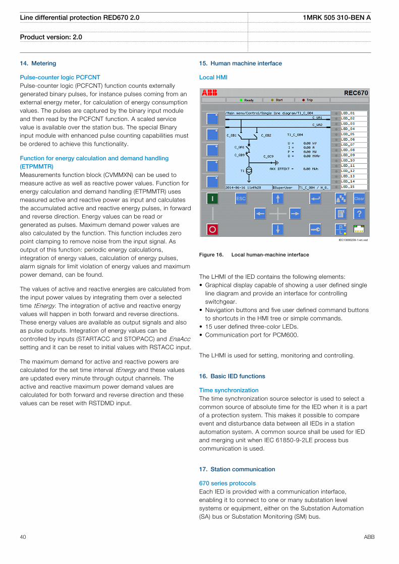
14. Metering
Pulse-counter logic PCFCNTPulse-counter logic (PCFCNT) function counts externallygenerated binary pulses, for instance pulses coming from anexternal energy meter, for calculation of energy consumptionvalues. The pulses are captured by the binary input moduleand then read by the PCFCNT function. A scaled servicevalue is available over the station bus. The special Binaryinput module with enhanced pulse counting capabilities mustbe ordered to achieve this functionality.
Function for energy calculation and demand handling(ETPMMTR)Measurements function block (CVMMXN) can be used tomeasure active as well as reactive power values. Function forenergy calculation and demand handling (ETPMMTR) usesmeasured active and reactive power as input and calculatesthe accumulated active and reactive energy pulses, in forwardand reverse direction. Energy values can be read orgenerated as pulses. Maximum demand power values arealso calculated by the function. This function includes zeropoint clamping to remove noise from the input signal. Asoutput of this function: periodic energy calculations,integration of energy values, calculation of energy pulses,alarm signals for limit violation of energy values and maximumpower demand, can be found.
The values of active and reactive energies are calculated fromthe input power values by integrating them over a selectedtime tEnergy. The integration of active and reactive energyvalues will happen in both forward and reverse directions.These energy values are available as output signals and alsoas pulse outputs. Integration of energy values can becontrolled by inputs (STARTACC and STOPACC) and EnaAccsetting and it can be reset to initial values with RSTACC input.
The maximum demand for active and reactive powers arecalculated for the set time interval tEnergy and these valuesare updated every minute through output channels. Theactive and reactive maximum power demand values arecalculated for both forward and reverse direction and thesevalues can be reset with RSTDMD input.
15. Human machine interface
Local HMI
IEC13000239-1-en.vsd
IEC13000239 V1 EN
Figure 16. Local human-machine interface
The LHMI of the IED contains the following elements:• Graphical display capable of showing a user defined single
line diagram and provide an interface for controllingswitchgear.
• Navigation buttons and five user defined command buttonsto shortcuts in the HMI tree or simple commands.
• 15 user defined three-color LEDs.• Communication port for PCM600.
The LHMI is used for setting, monitoring and controlling.
16. Basic IED functions
Time synchronizationThe time synchronization source selector is used to select acommon source of absolute time for the IED when it is a partof a protection system. This makes it possible to compareevent and disturbance data between all IEDs in a stationautomation system. A common source shall be used for IEDand merging unit when IEC 61850-9-2LE process buscommunication is used.
17. Station communication
670 series protocolsEach IED is provided with a communication interface,enabling it to connect to one or many substation levelsystems or equipment, either on the Substation Automation(SA) bus or Substation Monitoring (SM) bus.
Line differential protection RED670 2.0 1MRK 505 310-BEN A
Product version: 2.0
40 ABB
Following communication protocols are available:
• IEC 61850-8-1 communication protocol• IEC 61850-9-2LE communication protocol• LON communication protocol• SPA or IEC 60870-5-103 communication protocol• DNP3.0 communication protocol
Theoretically, several protocols can be combined in the sameIED.
IEC 61850-8-1 communication protocolIEC 61850 Ed.1 or Ed.2 can be chosen by a setting inPCM600. The IED is equipped with single or double opticalEthernet rear ports (order dependent) for IEC 61850-8-1station bus communication. The IEC 61850-8-1communication is also possible from the optical Ethernet frontport. IEC 61850-8-1 protocol allows intelligent electricaldevices (IEDs) from different vendors to exchange informationand simplifies system engineering. IED-to-IED communicationusing GOOSE and client-server communication over MMS aresupported. Disturbance recording file (COMTRADE) uploadingcan be done over MMS or FTP.
IEC 61850-9-2LE communication protocolSingle optical Ethernet port communication standard IEC61850-9-2LE for process bus is provided. IEC 61850-9-2LEallows Non Conventional Instrument Transformers (NCIT) withMerging Units (MU) or stand alone Meging Units to exchangeinformation with the IED and simplifies SA engineering.
Serial communication, LONExisting stations with ABB station bus LON can be extendedwith use of the optical LON interface. This allows full SAfunctionality including peer-to-peer messaging andcooperation between existing ABB IED's and the new IED670.
SPA communication protocolA single glass or plastic port is provided for the ABB SPAprotocol. This allows extensions of simple substationautomation systems but the main use is for SubstationMonitoring Systems SMS.
IEC 60870-5-103 communication protocolA single glass or plastic port is provided for the IEC60870-5-103 standard. This allows design of simplesubstation automation systems including equipment fromdifferent vendors. Disturbance files uploading is provided.
DNP3.0 communication protocolAn electrical RS485 and an optical Ethernet port is availablefor the DNP3.0 communication. DNP3.0 Level 2communication with unsolicited events, time synchronizingand disturbance reporting is provided for communication toRTUs, Gateways or HMI systems.
Multiple command and transmitWhen 670 IED's are used in Substation Automation systemswith LON, SPA or IEC 60870-5-103 communication protocolsthe Event and Multiple Command function blocks are used asthe communication interface for vertical communication tostation HMI and gateway and as interface for horizontal peer-to-peer communication (over LON only).
IEC 62439-3 Parallel Redundant ProtocolRedundant station bus communication according to IEC62439-3 Edition 1 and IEC 62439-3 Edition 2 are available asoptions in 670 series IEDs. IEC 62439-3 parallel redundantprotocol is an optional quantity and the selection is made atordering. Redundant station bus communication according toIEC 62439-3 uses both port AB and port CD on the OEMmodule.
18. Remote communication
Analog and binary signal transfer to remote endThree analog and eight binary signals can be exchangedbetween two IEDs. This functionality is mainly used for theline differential protection. However it can be used in otherproducts as well. An IED can communicate with up to 4remote IEDs.
Binary signal transfer to remote end, 192 signalsIf the communication channel is used for transfer of binarysignals only, up to 192 binary signals can be exchangedbetween two IEDs. For example, this functionality can beused to send information such as status of primaryswitchgear apparatus or intertripping signals to the remoteIED. An IED can communicate with up to 4 remote IEDs.
Line data communication module, short, medium and longrange LDCMThe line data communication module (LDCM) is used forcommunication between the IEDs situated at distances <110km or from the IED to optical to electrical converter with G.703 or G.703E1 interface located on a distances <3 kmaway. The LDCM module sends and receives data, to andfrom another LDCM module. The IEEE/ANSI C37.94 standardformat is used.
Galvanic X.21 line data communication module X.21-LDCMA module with built-in galvanic X.21 converter which e.g. canbe connected to modems for pilot wires is also available.
Galvanic interface G.703 resp G.703E1The external galvanic data communication converter G.703/G.703E1 makes an optical-to-galvanic conversion forconnection to a multiplexer. These units are designed for 64kbit/s resp 2Mbit/s operation. The converter is delivered with19” rack mounting accessories.
Line differential protection RED670 2.0 1MRK 505 310-BEN A
Product version: 2.0
ABB 41
19. Hardware description
Hardware modulesPower supply module PSMThe power supply module is used to provide the correctinternal voltages and full isolation between the IED and thebattery system. An internal fail alarm output is available.
Binary input module BIMThe binary input module has 16 optically isolated inputs andis available in two versions, one standard and one withenhanced pulse counting capabilities on the inputs to beused with the pulse counter function. The binary inputs arefreely programmable and can be used for the input of logicalsignals to any of the functions. They can also be included inthe disturbance recording and event-recording functions. Thisenables extensive monitoring and evaluation of operation ofthe IED and for all associated electrical circuits.
Binary output module BOMThe binary output module has 24 independent output relaysand is used for trip output or any signaling purpose.
Static binary output module SOMThe static binary output module has six fast static outputsand six change over output relays for use in applications withhigh speed requirements.
Binary input/output module IOMThe binary input/output module is used when only a few inputand output channels are needed. The ten standard outputchannels are used for trip output or any signaling purpose.The two high speed signal output channels are used forapplications where short operating time is essential. Eightoptically isolated binary inputs cater for required binary inputinformation.
mA input module MIMThe milli-ampere input module is used to interface transducersignals in the –20 to +20 mA range from for example OLTCposition, temperature or pressure transducers. The modulehas six independent, galvanically separated channels.
Optical ethernet module OEMThe optical fast-ethernet module is used to connect an IED tothe communication buses (like the station bus) that use theIEC 61850-8-1 protocol (OEM rear port A, B). The processbus use the IEC 61850-9-2LE protocol (OEM rear port C, D).The module has one or two optical ports with ST connectors.
Serial and LON communication module SLM, supports SPA/IEC 60870-5-103, LON and DNP 3.0The serial and LON communication module (SLM) is used forSPA, IEC 60870-5-103, DNP3 and LON communication. Themodule has two optical communication ports for plastic/plastic, plastic/glass or glass/glass. One port is used for serialcommunication (SPA, IEC 60870-5-103 and DNP3 port) andone port is dedicated for LON communication.
Line data communication module LDCMEach module has one optical port, one for each remote endto which the IED communicates.
Alternative cards for Long range (1550 nm single mode),Medium range (1310 nm single mode) and Short range (850nm multi mode) are available.
Galvanic X.21 line data communication module X.21-LDCMThe galvanic X.21 line data communication module is used forconnection to telecommunication equipment, for exampleleased telephone lines. The module supports 64 kbit/s datacommunication between IEDs.
Examples of applications:
• Line differential protection• Binary signal transfer
Galvanic RS485 serial communication moduleThe Galvanic RS485 communication module (RS485) is usedfor DNP3.0 and IEC 60870-5-103 communication. Themodule has one RS485 communication port. The RS485 is abalanced serial communication that can be used either in 2-wire or 4-wire connections. A 2-wire connection uses thesame signal for RX and TX and is a multidrop communicationwith no dedicated Master or slave. This variant requireshowever a control of the output. The 4-wire connection hasseparated signals for RX and TX multidrop communicationwith a dedicated Master and the rest are slaves. No specialcontrol signal is needed in this case.
GPS time synchronization module GTMThis module includes a GPS receiver used for timesynchronization. The GPS has one SMA contact forconnection to an antenna. It also includes an optical PPS ST-connector output.
IRIG-B Time synchronizing moduleThe IRIG-B time synchronizing module is used for accuratetime synchronizing of the IED from a station clock.
The Pulse Per Second (PPS) input shall be used forsynchronizing when IEC 61850-9-2LE is used.
Electrical (BNC) and optical connection (ST) for 0XX and 12XIRIG-B support.
Transformer input module TRMThe transformer input module is used to galvanically separateand adapt the secondary currents and voltages generated bythe measuring transformers. The module has twelve inputs indifferent combinations of currents and voltage inputs.
Alternative connectors of Ring lug or Compression type canbe ordered.
High impedance resistor unitThe high impedance resistor unit, with resistors for pick-upvalue setting and a voltage dependent resistor, is available in
Line differential protection RED670 2.0 1MRK 505 310-BEN A
Product version: 2.0
42 ABB
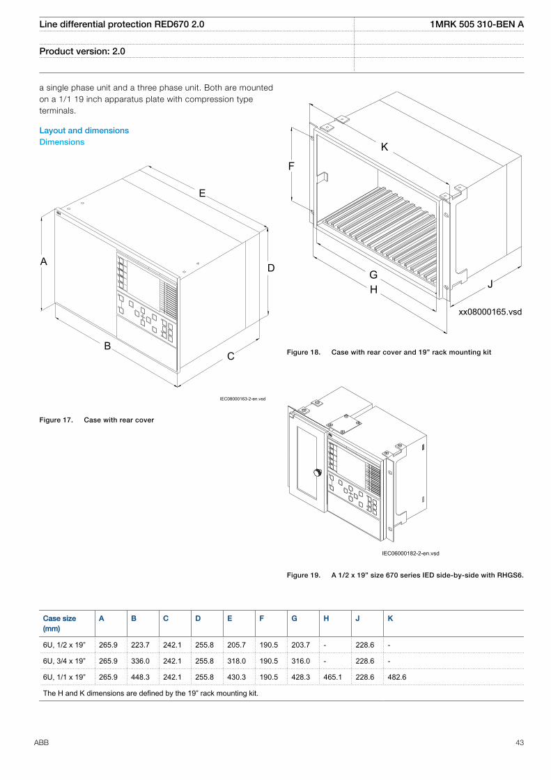
a single phase unit and a three phase unit. Both are mountedon a 1/1 19 inch apparatus plate with compression typeterminals.
Layout and dimensionsDimensions
CB
D
E
A
IEC08000163-2-en.vsd
IEC08000163 V2 EN
Figure 17. Case with rear cover
xx08000165.vsd
JG
F
K
H
IEC08000165 V1 EN
Figure 18. Case with rear cover and 19” rack mounting kit
IEC06000182-2-en.vsdIEC06000182 V2 EN
Figure 19. A 1/2 x 19” size 670 series IED side-by-side with RHGS6.
Case size(mm)
A B C D E F G H J K
6U, 1/2 x 19” 265.9 223.7 242.1 255.8 205.7 190.5 203.7 - 228.6 -
6U, 3/4 x 19” 265.9 336.0 242.1 255.8 318.0 190.5 316.0 - 228.6 -
6U, 1/1 x 19” 265.9 448.3 242.1 255.8 430.3 190.5 428.3 465.1 228.6 482.6
The H and K dimensions are defined by the 19” rack mounting kit.
Line differential protection RED670 2.0 1MRK 505 310-BEN A
Product version: 2.0
ABB 43

Mounting alternatives• 19” rack mounting kit• Flush mounting kit with cut-out dimensions:
– 1/2 case size (h) 254.3 mm (w) 210.1 mm– 3/4 case size (h) 254.3 mm (w) 322.4 mm– 1/1 case size (h) 254.3 mm (w) 434.7 mm
• Wall mounting kit
See ordering for details about available mounting alternatives.
Line differential protection RED670 2.0 1MRK 505 310-BEN A
Product version: 2.0
44 ABB

20. Connection diagrams
Connection diagramsThe connection diagrams are delivered on the IEDConnectivity package DVD as part of the product delivery.
The latest versions of the connection diagrams can bedownloaded from http://www.abb.com/substationautomation.
Connection diagrams for Customized products
Connection diagram, 670 series 2.0 1MRK002801-AE
Connection diagrams for Configured products
Connection diagram, RED670 2.0, A31 1MRK002803-DA
Connection diagram, RED670 2.0, B31 1MRK002803-DB
Connection diagram, RED670 2.0, A32 1MRK002803-DC
Connection diagram, RED670 2.0, B32 1MRK002803-DD
Line differential protection RED670 2.0 1MRK 505 310-BEN A
Product version: 2.0
ABB 45
21. Technical data
General
Definitions
Reference value The specified value of an influencing factor to which are referred the characteristics of the equipment
Nominal range The range of values of an influencing quantity (factor) within which, under specified conditions, the equipment meets thespecified requirements
Operative range The range of values of a given energizing quantity for which the equipment, under specified conditions, is able to perform itsintended functions according to the specified requirements
Energizing quantities, rated values and limitsAnalog inputs
Table 2. TRM - Energizing quantities, rated values and limits for protection transformer modules
Quantity Rated value Nominal range
Current Ir = 1 or 5 A (0.2-40) × Ir
Operative range (0-100) x Ir
Permissive overload 4 × Ir cont.100 × Ir for 1 s *)
Burden < 150 mVA at Ir = 5 A< 20 mVA at Ir = 1 A
Ac voltage Ur = 110 V 0.5–288 V
Operative range (0–340) V
Permissive overload 420 V cont.450 V 10 s
Burden < 20 mVA at 110 V
Frequency fr = 50/60 Hz ± 5%
*) max. 350 A for 1 s when COMBITEST test switch is included.
Line differential protection RED670 2.0 1MRK 505 310-BEN A
Product version: 2.0
46 ABB
Table 3. TRM - Energizing quantities, rated values and limits for measuring transformer modules
Quantity Rated value Nominal range
Current Ir = 1 or 5 A (0-1.8) × Irat Ir = 1 A(0-1.6) × Irat Ir = 5 A
Permissive overload 1.1 × Ir cont.1.8 × Ir for 30 min at Ir = 1 A1.6 × Ir for 30 min at Ir = 5 A
Burden < 350 mVA at Ir = 5 A< 200 mVA at Ir = 1 A
Ac voltage Ur = 110 V 0.5–288 V
Operative range (0–340) V
Permissive overload 420 V cont.450 V 10 s
Burden < 20 mVA at 110 V
Frequency fr = 50/60 Hz ± 5%
Table 4. MIM - mA input module
Quantity: Rated value: Nominal range:
Input resistance Rin = 194 Ohm -
Input range ± 5, ± 10, ± 20mA0-5, 0-10, 0-20, 4-20mA
-
Power consumptioneach mA-boardeach mA input
£ 2 W£ 0.1 W
-
Table 5. OEM - Optical ethernet module
Quantity Rated value
Number of channels 1 or 2 (port A, B for IEC 61850-8-1 and port C, D for IEC 61850-9-2LE)
Standard IEEE 802.3u 100BASE-FX
Type of fiber 62.5/125 mm multimode fibre
Wave length 1300 nm
Optical connector Type ST
Communication speed Fast Ethernet 100 Mbit/s
Auxiliary DC voltage
Table 6. PSM - Power supply module
Quantity Rated value Nominal range
Auxiliary dc voltage, EL (input) EL = (24 - 60) VEL = (90 - 250) V
EL ± 20%EL ± 20%
Power consumption 50 W typically -
Auxiliary DC power in-rush < 10 A during 0.1 s -
Line differential protection RED670 2.0 1MRK 505 310-BEN A
Product version: 2.0
ABB 47
Binary inputs and outputs
Table 7. BIM - Binary input module
Quantity Rated value Nominal range
Binary inputs 16 -
DC voltage, RL 24/30 V48/60 V110/125 V220/250 V
RL ± 20%RL ± 20%RL ± 20%RL ± 20%
Power consumption24/30 V, 50mA48/60 V, 50mA110/125 V, 50mA220/250 V, 50mA220/250 V, 110mA
max. 0.05 W/inputmax. 0.1 W/inputmax. 0.2 W/inputmax. 0.4 W/inputmax. 0.5 W/input
-
Counter input frequency 10 pulses/s max -
Oscillating signal discriminator Blocking settable 1–40 HzRelease settable 1–30 Hz
Debounce filter Settable 1–20ms
Table 8. BIM - Binary input module with enhanced pulse counting capabilities
Quantity Rated value Nominal range
Binary inputs 16 -
DC voltage, RL 24/30 V48/60 V110/125 V220/250 V
RL ± 20%RL ± 20%RL ± 20%RL ± 20%
Power consumption24/30 V48/60 V110/125 V220/250 V
max. 0.05 W/inputmax. 0.1 W/inputmax. 0.2 W/inputmax. 0.4 W/input
-
Counter input frequency 10 pulses/s max -
Balanced counter input frequency 40 pulses/s max -
Oscillating signal discriminator Blocking settable 1–40 HzRelease settable 1–30 Hz
Line differential protection RED670 2.0 1MRK 505 310-BEN A
Product version: 2.0
48 ABB
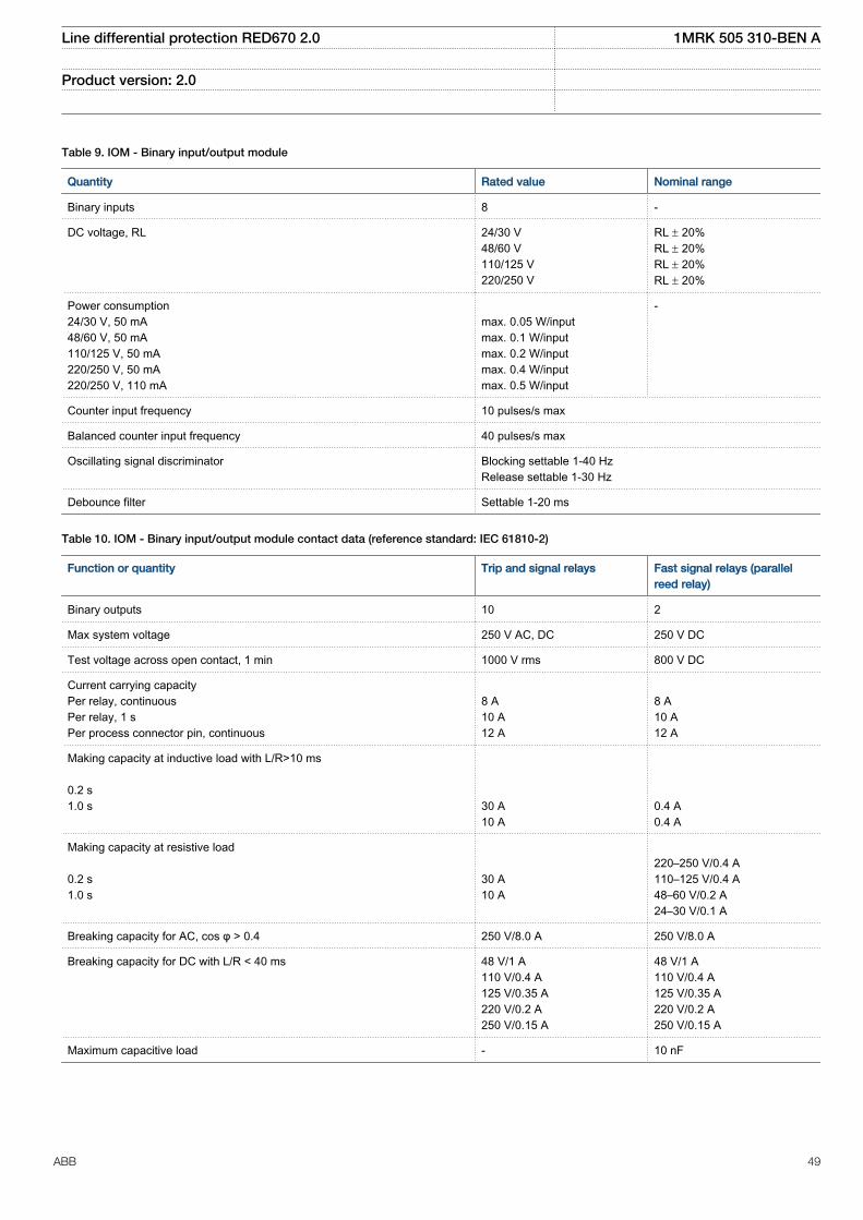
Table 9. IOM - Binary input/output module
Quantity Rated value Nominal range
Binary inputs 8 -
DC voltage, RL 24/30 V48/60 V110/125 V220/250 V
RL ± 20%RL ± 20%RL ± 20%RL ± 20%
Power consumption24/30 V, 50 mA48/60 V, 50 mA110/125 V, 50 mA220/250 V, 50 mA220/250 V, 110 mA
max. 0.05 W/inputmax. 0.1 W/inputmax. 0.2 W/inputmax. 0.4 W/inputmax. 0.5 W/input
-
Counter input frequency 10 pulses/s max
Balanced counter input frequency 40 pulses/s max
Oscillating signal discriminator Blocking settable 1-40 HzRelease settable 1-30 Hz
Debounce filter Settable 1-20 ms
Table 10. IOM - Binary input/output module contact data (reference standard: IEC 61810-2)
Function or quantity Trip and signal relays Fast signal relays (parallelreed relay)
Binary outputs 10 2
Max system voltage 250 V AC, DC 250 V DC
Test voltage across open contact, 1 min 1000 V rms 800 V DC
Current carrying capacityPer relay, continuousPer relay, 1 sPer process connector pin, continuous
8 A10 A12 A
8 A10 A12 A
Making capacity at inductive load with L/R>10 ms 0.2 s1.0 s
30 A10 A
0.4 A0.4 A
Making capacity at resistive load 0.2 s1.0 s
30 A10 A
220–250 V/0.4 A110–125 V/0.4 A48–60 V/0.2 A24–30 V/0.1 A
Breaking capacity for AC, cos φ > 0.4 250 V/8.0 A 250 V/8.0 A
Breaking capacity for DC with L/R < 40 ms 48 V/1 A110 V/0.4 A125 V/0.35 A220 V/0.2 A250 V/0.15 A
48 V/1 A110 V/0.4 A125 V/0.35 A220 V/0.2 A250 V/0.15 A
Maximum capacitive load - 10 nF
Line differential protection RED670 2.0 1MRK 505 310-BEN A
Product version: 2.0
ABB 49
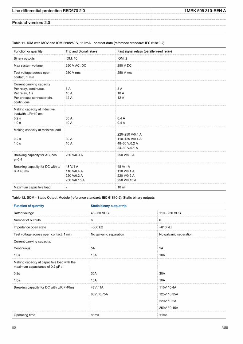
Table 11. IOM with MOV and IOM 220/250 V, 110mA - contact data (reference standard: IEC 61810-2)
Function or quantity Trip and Signal relays Fast signal relays (parallel reed relay)
Binary outputs IOM: 10 IOM: 2
Max system voltage 250 V AC, DC 250 V DC
Test voltage across opencontact, 1 min
250 V rms 250 V rms
Current carrying capacityPer relay, continuousPer relay, 1 sPer process connector pin,continuous
8 A10 A12 A
8 A10 A12 A
Making capacity at inductiveloadwith L/R>10 ms0.2 s1.0 s
30 A10 A
0.4 A0.4 A
Making capacity at resistive load 0.2 s1.0 s
30 A10 A
220–250 V/0.4 A110–125 V/0.4 A48–60 V/0.2 A24–30 V/0.1 A
Breaking capacity for AC, cosj>0.4
250 V/8.0 A 250 V/8.0 A
Breaking capacity for DC with L/R < 40 ms
48 V/1 A110 V/0.4 A220 V/0.2 A250 V/0.15 A
48 V/1 A110 V/0.4 A220 V/0.2 A250 V/0.15 A
Maximum capacitive load - 10 nF
Table 12. SOM - Static Output Module (reference standard: IEC 61810-2): Static binary outputs
Function of quantity Static binary output trip
Rated voltage 48 - 60 VDC 110 - 250 VDC
Number of outputs 6 6
Impedance open state ~300 kΩ ~810 kΩ
Test voltage across open contact, 1 min No galvanic separation No galvanic separation
Current carrying capacity:
Continuous 5A 5A
1.0s 10A 10A
Making capacity at capacitive load with themaximum capacitance of 0.2 μF :
0.2s 30A 30A
1.0s 10A 10A
Breaking capacity for DC with L/R ≤ 40ms 48V / 1A 110V / 0.4A
60V / 0.75A 125V / 0.35A
220V / 0.2A
250V / 0.15A
Operating time <1ms <1ms
Line differential protection RED670 2.0 1MRK 505 310-BEN A
Product version: 2.0
50 ABB
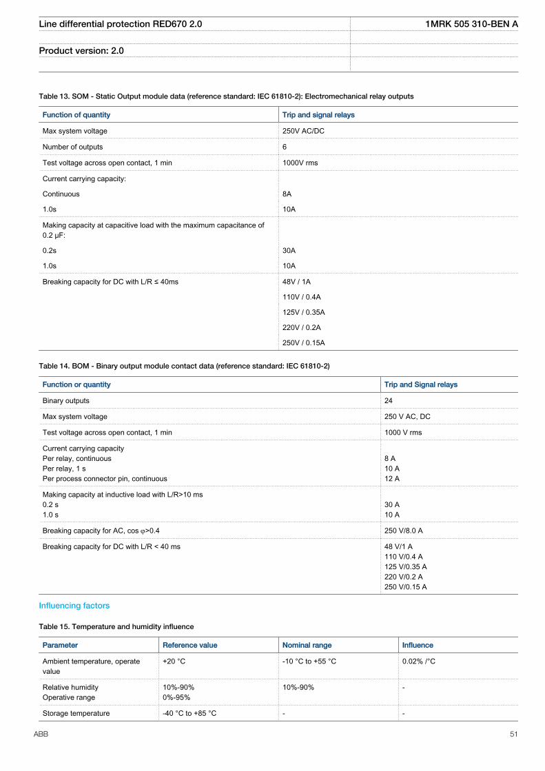
Table 13. SOM - Static Output module data (reference standard: IEC 61810-2): Electromechanical relay outputs
Function of quantity Trip and signal relays
Max system voltage 250V AC/DC
Number of outputs 6
Test voltage across open contact, 1 min 1000V rms
Current carrying capacity:
Continuous 8A
1.0s 10A
Making capacity at capacitive load with the maximum capacitance of0.2 μF:
0.2s 30A
1.0s 10A
Breaking capacity for DC with L/R ≤ 40ms 48V / 1A
110V / 0.4A
125V / 0.35A
220V / 0.2A
250V / 0.15A
Table 14. BOM - Binary output module contact data (reference standard: IEC 61810-2)
Function or quantity Trip and Signal relays
Binary outputs 24
Max system voltage 250 V AC, DC
Test voltage across open contact, 1 min 1000 V rms
Current carrying capacityPer relay, continuousPer relay, 1 sPer process connector pin, continuous
8 A10 A12 A
Making capacity at inductive load with L/R>10 ms0.2 s1.0 s
30 A10 A
Breaking capacity for AC, cos j>0.4 250 V/8.0 A
Breaking capacity for DC with L/R < 40 ms 48 V/1 A110 V/0.4 A125 V/0.35 A220 V/0.2 A250 V/0.15 A
Influencing factors
Table 15. Temperature and humidity influence
Parameter Reference value Nominal range Influence
Ambient temperature, operatevalue
+20 °C -10 °C to +55 °C 0.02% /°C
Relative humidityOperative range
10%-90%0%-95%
10%-90% -
Storage temperature -40 °C to +85 °C - -
Line differential protection RED670 2.0 1MRK 505 310-BEN A
Product version: 2.0
ABB 51
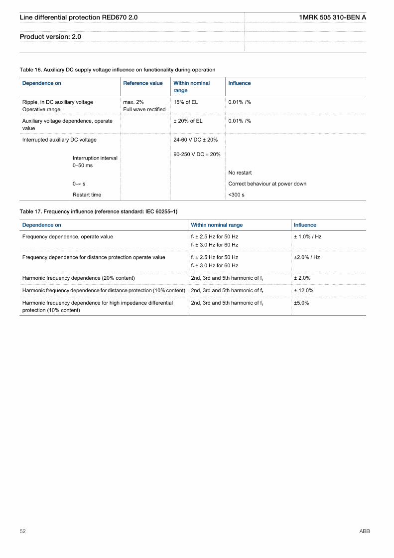
Table 16. Auxiliary DC supply voltage influence on functionality during operation
Dependence on Reference value Within nominalrange
Influence
Ripple, in DC auxiliary voltageOperative range
max. 2%Full wave rectified
15% of EL 0.01% /%
Auxiliary voltage dependence, operatevalue
± 20% of EL 0.01% /%
Interrupted auxiliary DC voltage
24-60 V DC ± 20% 90-250 V DC ± 20%
Interruption interval0–50 ms
No restart
0–∞ s Correct behaviour at power down
Restart time <300 s
Table 17. Frequency influence (reference standard: IEC 60255–1)
Dependence on Within nominal range Influence
Frequency dependence, operate value fr ± 2.5 Hz for 50 Hzfr ± 3.0 Hz for 60 Hz
± 1.0% / Hz
Frequency dependence for distance protection operate value fr ± 2.5 Hz for 50 Hzfr ± 3.0 Hz for 60 Hz
±2.0% / Hz
Harmonic frequency dependence (20% content) 2nd, 3rd and 5th harmonic of fr ± 2.0%
Harmonic frequency dependence for distance protection (10% content) 2nd, 3rd and 5th harmonic of fr ± 12.0%
Harmonic frequency dependence for high impedance differentialprotection (10% content)
2nd, 3rd and 5th harmonic of fr ±5.0%
Line differential protection RED670 2.0 1MRK 505 310-BEN A
Product version: 2.0
52 ABB
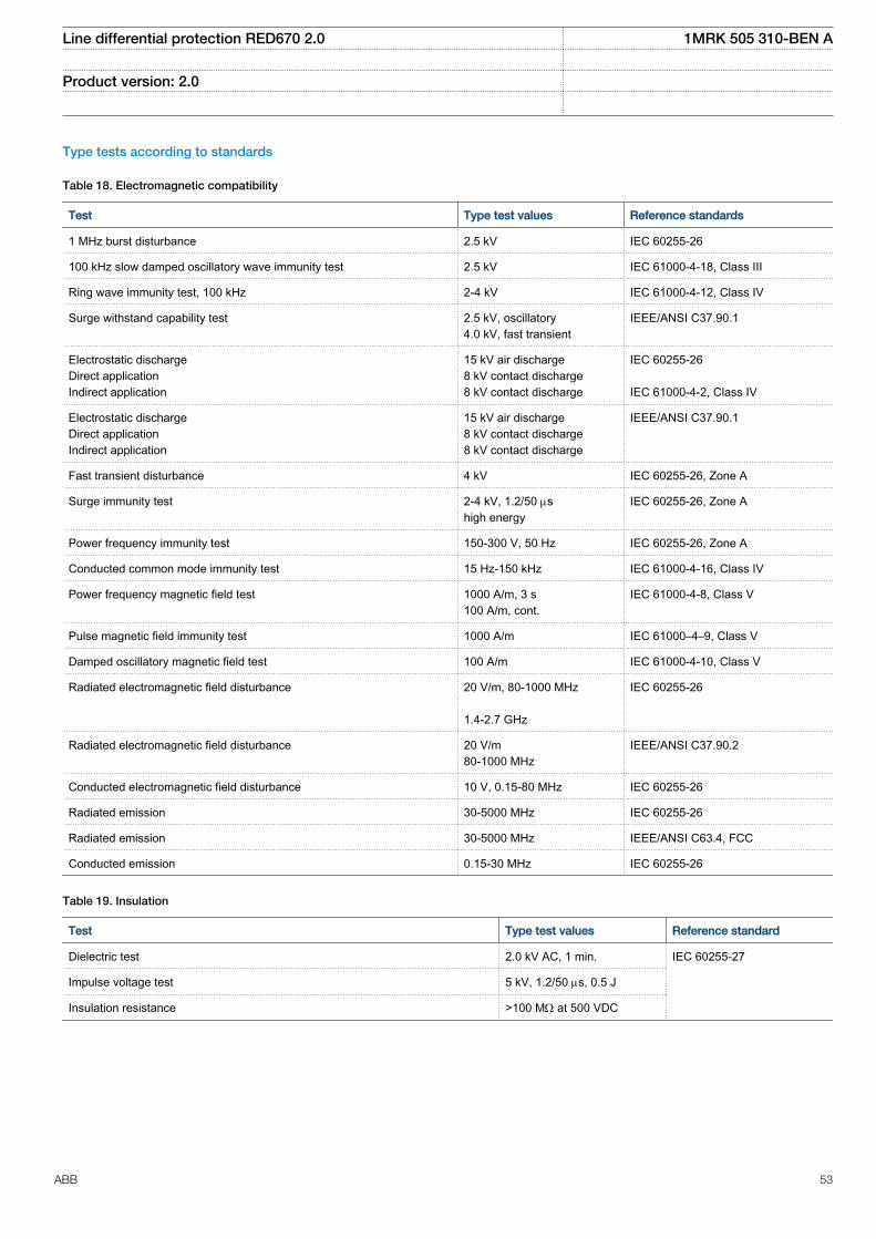
Type tests according to standards
Table 18. Electromagnetic compatibility
Test Type test values Reference standards
1 MHz burst disturbance 2.5 kV IEC 60255-26
100 kHz slow damped oscillatory wave immunity test 2.5 kV IEC 61000-4-18, Class III
Ring wave immunity test, 100 kHz 2-4 kV IEC 61000-4-12, Class IV
Surge withstand capability test 2.5 kV, oscillatory4.0 kV, fast transient
IEEE/ANSI C37.90.1
Electrostatic dischargeDirect applicationIndirect application
15 kV air discharge8 kV contact discharge8 kV contact discharge
IEC 60255-26 IEC 61000-4-2, Class IV
Electrostatic dischargeDirect applicationIndirect application
15 kV air discharge8 kV contact discharge8 kV contact discharge
IEEE/ANSI C37.90.1
Fast transient disturbance 4 kV IEC 60255-26, Zone A
Surge immunity test 2-4 kV, 1.2/50 mshigh energy
IEC 60255-26, Zone A
Power frequency immunity test 150-300 V, 50 Hz IEC 60255-26, Zone A
Conducted common mode immunity test 15 Hz-150 kHz IEC 61000-4-16, Class IV
Power frequency magnetic field test 1000 A/m, 3 s100 A/m, cont.
IEC 61000-4-8, Class V
Pulse magnetic field immunity test 1000 A/m IEC 61000–4–9, Class V
Damped oscillatory magnetic field test 100 A/m IEC 61000-4-10, Class V
Radiated electromagnetic field disturbance 20 V/m, 80-1000 MHz 1.4-2.7 GHz
IEC 60255-26
Radiated electromagnetic field disturbance 20 V/m80-1000 MHz
IEEE/ANSI C37.90.2
Conducted electromagnetic field disturbance 10 V, 0.15-80 MHz IEC 60255-26
Radiated emission 30-5000 MHz IEC 60255-26
Radiated emission 30-5000 MHz IEEE/ANSI C63.4, FCC
Conducted emission 0.15-30 MHz IEC 60255-26
Table 19. Insulation
Test Type test values Reference standard
Dielectric test 2.0 kV AC, 1 min. IEC 60255-27
Impulse voltage test 5 kV, 1.2/50 ms, 0.5 J
Insulation resistance >100 MW at 500 VDC
Line differential protection RED670 2.0 1MRK 505 310-BEN A
Product version: 2.0
ABB 53
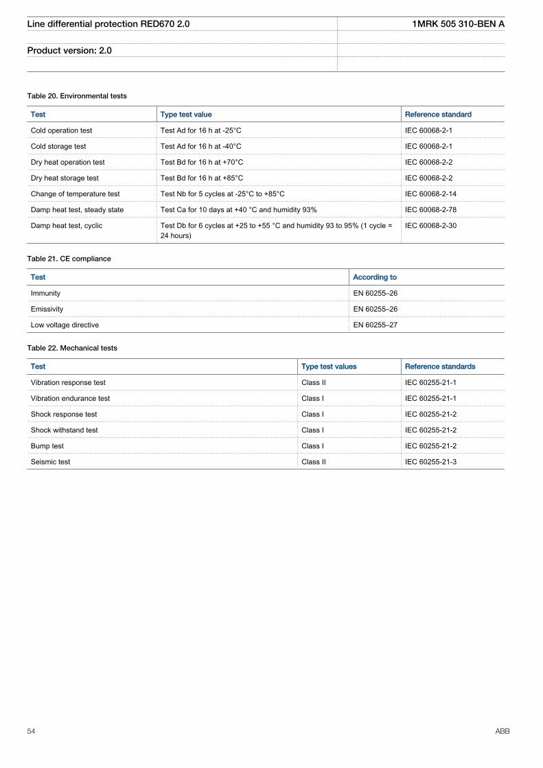
Table 20. Environmental tests
Test Type test value Reference standard
Cold operation test Test Ad for 16 h at -25°C IEC 60068-2-1
Cold storage test Test Ad for 16 h at -40°C IEC 60068-2-1
Dry heat operation test Test Bd for 16 h at +70°C IEC 60068-2-2
Dry heat storage test Test Bd for 16 h at +85°C IEC 60068-2-2
Change of temperature test Test Nb for 5 cycles at -25°C to +85°C IEC 60068-2-14
Damp heat test, steady state Test Ca for 10 days at +40 °C and humidity 93% IEC 60068-2-78
Damp heat test, cyclic Test Db for 6 cycles at +25 to +55 °C and humidity 93 to 95% (1 cycle =24 hours)
IEC 60068-2-30
Table 21. CE compliance
Test According to
Immunity EN 60255–26
Emissivity EN 60255–26
Low voltage directive EN 60255–27
Table 22. Mechanical tests
Test Type test values Reference standards
Vibration response test Class II IEC 60255-21-1
Vibration endurance test Class I IEC 60255-21-1
Shock response test Class I IEC 60255-21-2
Shock withstand test Class I IEC 60255-21-2
Bump test Class I IEC 60255-21-2
Seismic test Class II IEC 60255-21-3
Line differential protection RED670 2.0 1MRK 505 310-BEN A
Product version: 2.0
54 ABB
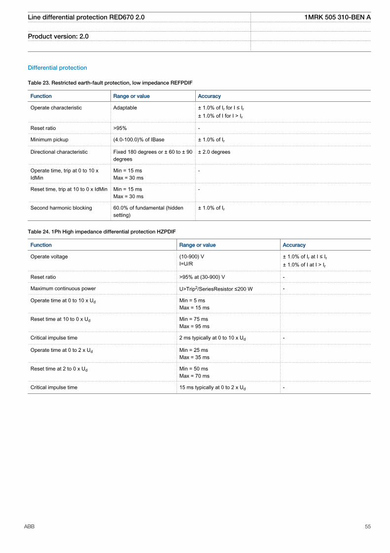
Differential protection
Table 23. Restricted earth-fault protection, low impedance REFPDIF
Function Range or value Accuracy
Operate characteristic Adaptable ± 1.0% of Ir for I ≤ Ir± 1.0% of I for I > Ir
Reset ratio >95% -
Minimum pickup (4.0-100.0)% of IBase ± 1.0% of Ir
Directional characteristic Fixed 180 degrees or ± 60 to ± 90degrees
± 2.0 degrees
Operate time, trip at 0 to 10 xIdMin
Min = 15 msMax = 30 ms
-
Reset time, trip at 10 to 0 x IdMin Min = 15 msMax = 30 ms
-
Second harmonic blocking 60.0% of fundamental (hiddensetting)
± 1.0% of Ir
Table 24. 1Ph High impedance differential protection HZPDIF
Function Range or value Accuracy
Operate voltage (10-900) VI=U/R
± 1.0% of Ir at I ≤ Ir± 1.0% of I at I > Ir
Reset ratio >95% at (30-900) V -
Maximum continuous power U>Trip2/SeriesResistor ≤200 W -
Operate time at 0 to 10 x Ud Min = 5 msMax = 15 ms
Reset time at 10 to 0 x Ud Min = 75 msMax = 95 ms
Critical impulse time 2 ms typically at 0 to 10 x Ud -
Operate time at 0 to 2 x Ud Min = 25 msMax = 35 ms
Reset time at 2 to 0 x Ud Min = 50 msMax = 70 ms
Critical impulse time 15 ms typically at 0 to 2 x Ud -
Line differential protection RED670 2.0 1MRK 505 310-BEN A
Product version: 2.0
ABB 55
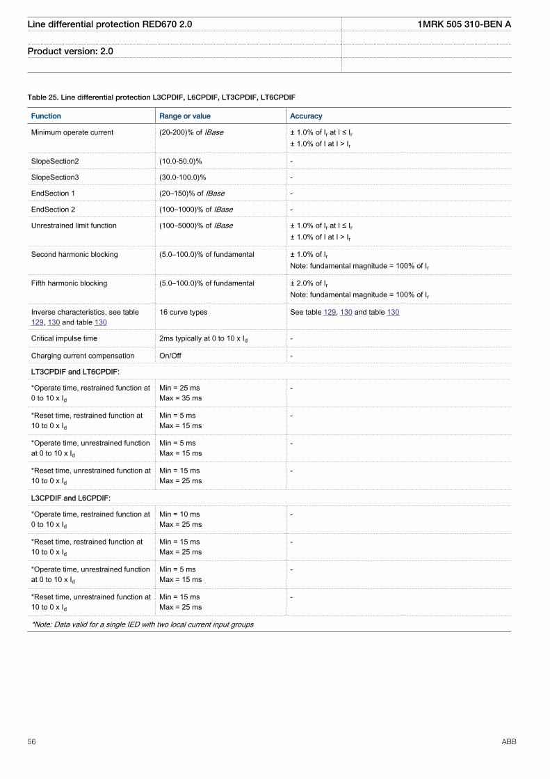
Table 25. Line differential protection L3CPDIF, L6CPDIF, LT3CPDIF, LT6CPDIF
Function Range or value Accuracy
Minimum operate current (20-200)% of IBase ± 1.0% of Ir at I ≤ Ir± 1.0% of I at I > Ir
SlopeSection2 (10.0-50.0)% -
SlopeSection3 (30.0-100.0)% -
EndSection 1 (20–150)% of IBase -
EndSection 2 (100–1000)% of IBase -
Unrestrained limit function (100–5000)% of IBase ± 1.0% of Ir at I ≤ Ir± 1.0% of I at I > Ir
Second harmonic blocking (5.0–100.0)% of fundamental ± 1.0% of IrNote: fundamental magnitude = 100% of Ir
Fifth harmonic blocking (5.0–100.0)% of fundamental ± 2.0% of IrNote: fundamental magnitude = 100% of Ir
Inverse characteristics, see table129, 130 and table 130
16 curve types See table 129, 130 and table 130
Critical impulse time 2ms typically at 0 to 10 x Id -
Charging current compensation On/Off -
LT3CPDIF and LT6CPDIF:
*Operate time, restrained function at0 to 10 x Id
Min = 25 msMax = 35 ms
-
*Reset time, restrained function at10 to 0 x Id
Min = 5 msMax = 15 ms
-
*Operate time, unrestrained functionat 0 to 10 x Id
Min = 5 msMax = 15 ms
-
*Reset time, unrestrained function at10 to 0 x Id
Min = 15 msMax = 25 ms
-
L3CPDIF and L6CPDIF:
*Operate time, restrained function at0 to 10 x Id
Min = 10 msMax = 25 ms
-
*Reset time, restrained function at10 to 0 x Id
Min = 15 msMax = 25 ms
-
*Operate time, unrestrained functionat 0 to 10 x Id
Min = 5 msMax = 15 ms
-
*Reset time, unrestrained function at10 to 0 x Id
Min = 15 msMax = 25 ms
-
*Note: Data valid for a single IED with two local current input groups
Line differential protection RED670 2.0 1MRK 505 310-BEN A
Product version: 2.0
56 ABB
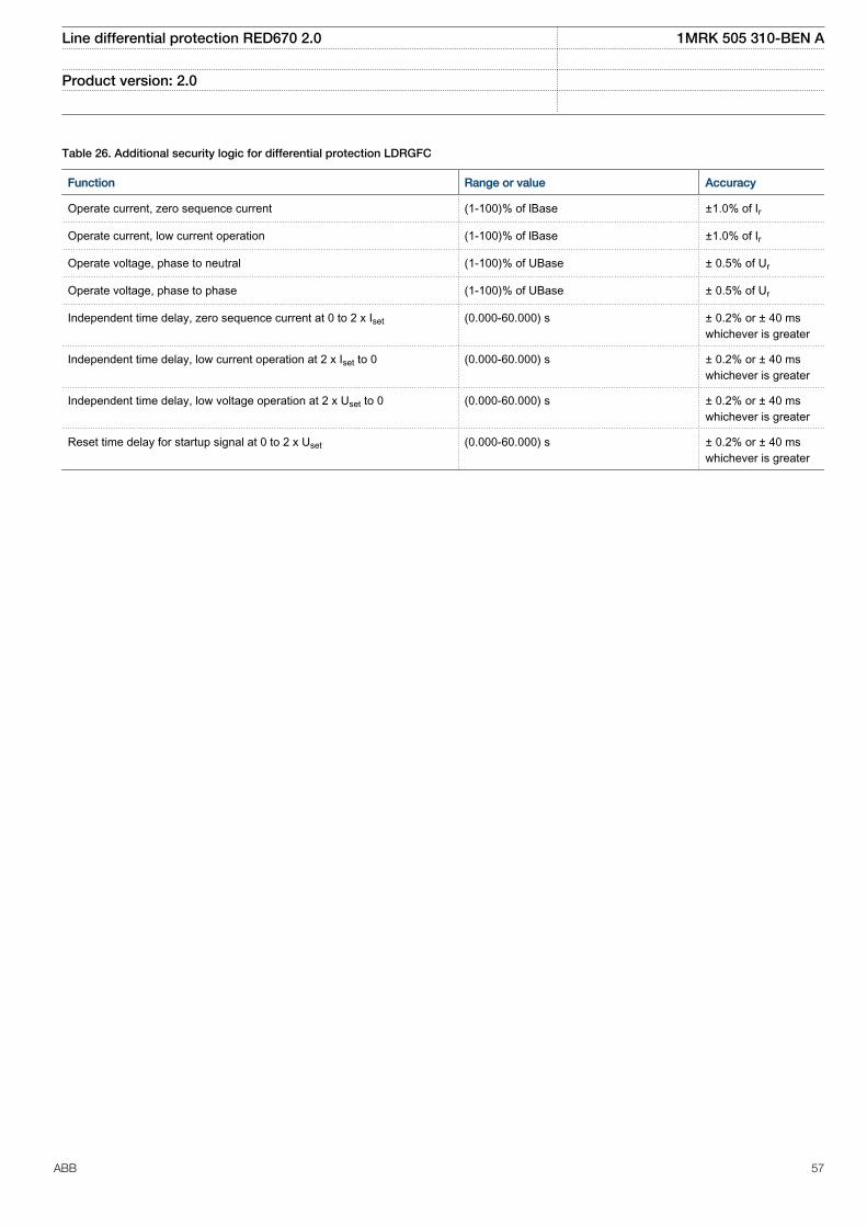
Table 26. Additional security logic for differential protection LDRGFC
Function Range or value Accuracy
Operate current, zero sequence current (1-100)% of lBase ±1.0% of Ir
Operate current, low current operation (1-100)% of lBase ±1.0% of Ir
Operate voltage, phase to neutral (1-100)% of UBase ± 0.5% of Ur
Operate voltage, phase to phase (1-100)% of UBase ± 0.5% of Ur
Independent time delay, zero sequence current at 0 to 2 x Iset (0.000-60.000) s ± 0.2% or ± 40 mswhichever is greater
Independent time delay, low current operation at 2 x Iset to 0 (0.000-60.000) s ± 0.2% or ± 40 mswhichever is greater
Independent time delay, low voltage operation at 2 x Uset to 0 (0.000-60.000) s ± 0.2% or ± 40 mswhichever is greater
Reset time delay for startup signal at 0 to 2 x Uset (0.000-60.000) s ± 0.2% or ± 40 mswhichever is greater
Line differential protection RED670 2.0 1MRK 505 310-BEN A
Product version: 2.0
ABB 57
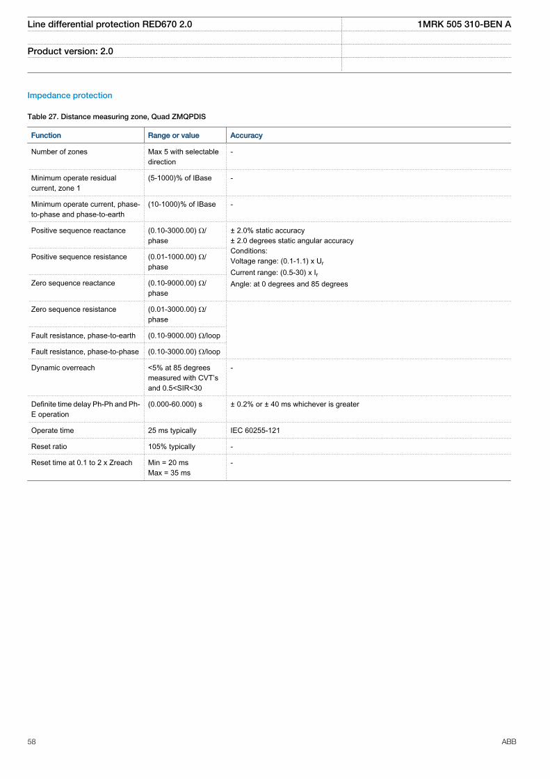
Impedance protection
Table 27. Distance measuring zone, Quad ZMQPDIS
Function Range or value Accuracy
Number of zones Max 5 with selectabledirection
-
Minimum operate residualcurrent, zone 1
(5-1000)% of IBase -
Minimum operate current, phase-to-phase and phase-to-earth
(10-1000)% of IBase -
Positive sequence reactance (0.10-3000.00) Ω/phase
± 2.0% static accuracy± 2.0 degrees static angular accuracyConditions:Voltage range: (0.1-1.1) x Ur
Current range: (0.5-30) x IrAngle: at 0 degrees and 85 degrees
Positive sequence resistance (0.01-1000.00) Ω/phase
Zero sequence reactance (0.10-9000.00) Ω/phase
Zero sequence resistance (0.01-3000.00) Ω/phase
Fault resistance, phase-to-earth (0.10-9000.00) Ω/loop
Fault resistance, phase-to-phase (0.10-3000.00) Ω/loop
Dynamic overreach <5% at 85 degreesmeasured with CVT’sand 0.5<SIR<30
-
Definite time delay Ph-Ph and Ph-E operation
(0.000-60.000) s ± 0.2% or ± 40 ms whichever is greater
Operate time 25 ms typically IEC 60255-121
Reset ratio 105% typically -
Reset time at 0.1 to 2 x Zreach Min = 20 msMax = 35 ms
-
Line differential protection RED670 2.0 1MRK 505 310-BEN A
Product version: 2.0
58 ABB
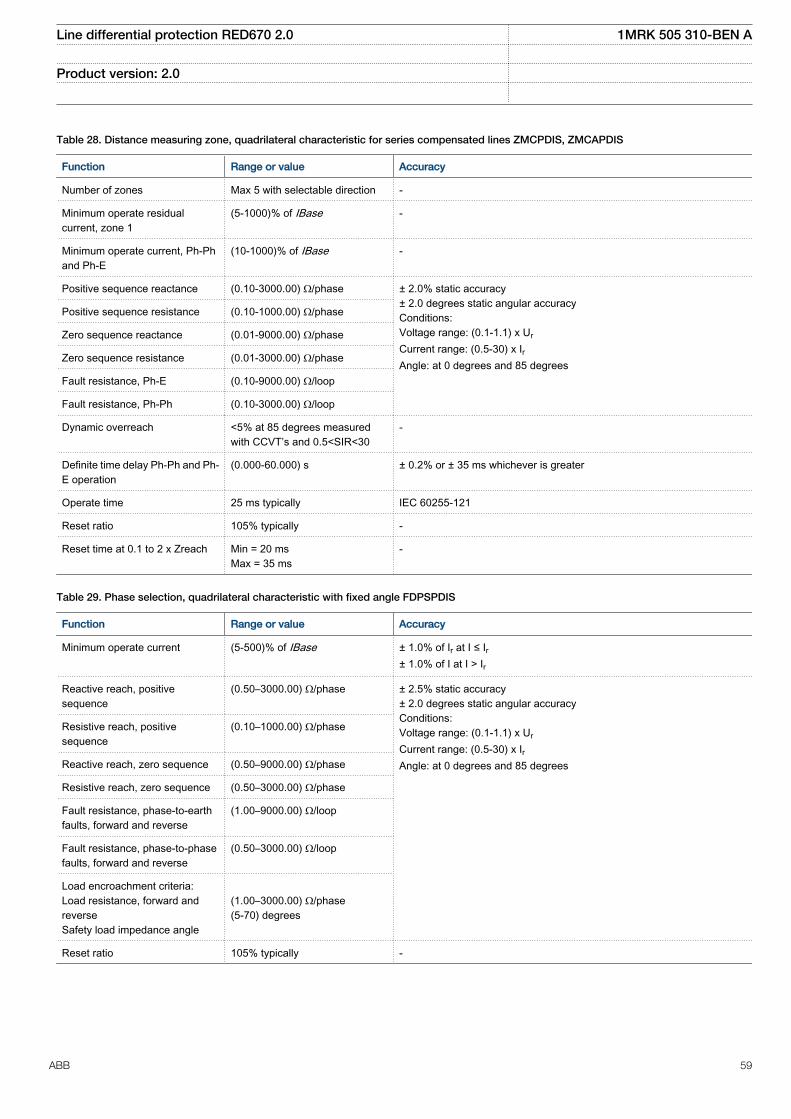
Table 28. Distance measuring zone, quadrilateral characteristic for series compensated lines ZMCPDIS, ZMCAPDIS
Function Range or value Accuracy
Number of zones Max 5 with selectable direction -
Minimum operate residualcurrent, zone 1
(5-1000)% of IBase -
Minimum operate current, Ph-Phand Ph-E
(10-1000)% of IBase -
Positive sequence reactance (0.10-3000.00) Ω/phase ± 2.0% static accuracy± 2.0 degrees static angular accuracyConditions:Voltage range: (0.1-1.1) x Ur
Current range: (0.5-30) x IrAngle: at 0 degrees and 85 degrees
Positive sequence resistance (0.10-1000.00) Ω/phase
Zero sequence reactance (0.01-9000.00) Ω/phase
Zero sequence resistance (0.01-3000.00) Ω/phase
Fault resistance, Ph-E (0.10-9000.00) Ω/loop
Fault resistance, Ph-Ph (0.10-3000.00) Ω/loop
Dynamic overreach <5% at 85 degrees measuredwith CCVT’s and 0.5<SIR<30
-
Definite time delay Ph-Ph and Ph-E operation
(0.000-60.000) s ± 0.2% or ± 35 ms whichever is greater
Operate time 25 ms typically IEC 60255-121
Reset ratio 105% typically -
Reset time at 0.1 to 2 x Zreach Min = 20 msMax = 35 ms
-
Table 29. Phase selection, quadrilateral characteristic with fixed angle FDPSPDIS
Function Range or value Accuracy
Minimum operate current (5-500)% of IBase ± 1.0% of Ir at I ≤ Ir± 1.0% of I at I > Ir
Reactive reach, positivesequence
(0.50–3000.00) Ω/phase ± 2.5% static accuracy± 2.0 degrees static angular accuracyConditions:Voltage range: (0.1-1.1) x Ur
Current range: (0.5-30) x IrAngle: at 0 degrees and 85 degrees
Resistive reach, positivesequence
(0.10–1000.00) Ω/phase
Reactive reach, zero sequence (0.50–9000.00) Ω/phase
Resistive reach, zero sequence (0.50–3000.00) Ω/phase
Fault resistance, phase-to-earthfaults, forward and reverse
(1.00–9000.00) Ω/loop
Fault resistance, phase-to-phasefaults, forward and reverse
(0.50–3000.00) Ω/loop
Load encroachment criteria:Load resistance, forward andreverseSafety load impedance angle
(1.00–3000.00) Ω/phase(5-70) degrees
Reset ratio 105% typically -
Line differential protection RED670 2.0 1MRK 505 310-BEN A
Product version: 2.0
ABB 59
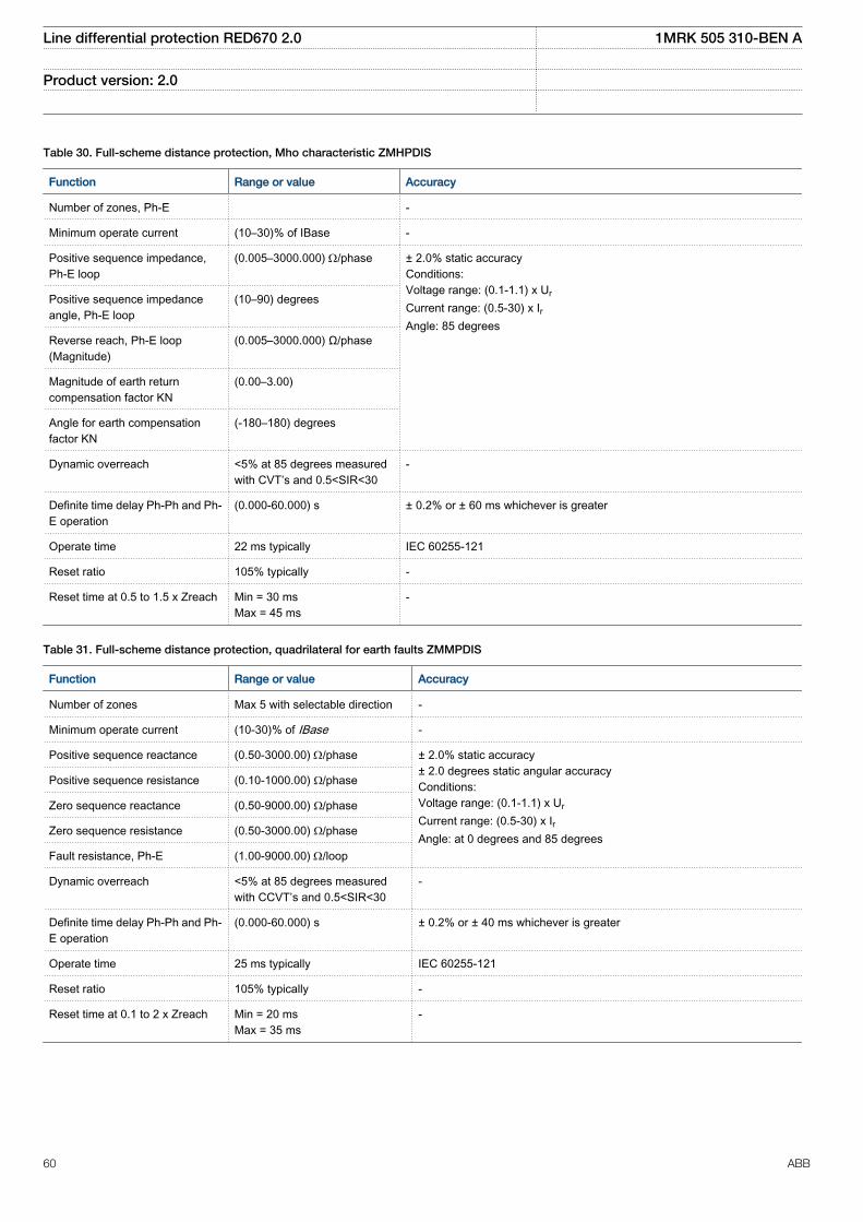
Table 30. Full-scheme distance protection, Mho characteristic ZMHPDIS
Function Range or value Accuracy
Number of zones, Ph-E -
Minimum operate current (10–30)% of IBase -
Positive sequence impedance,Ph-E loop
(0.005–3000.000) W/phase ± 2.0% static accuracyConditions:Voltage range: (0.1-1.1) x Ur
Current range: (0.5-30) x IrAngle: 85 degrees
Positive sequence impedanceangle, Ph-E loop
(10–90) degrees
Reverse reach, Ph-E loop(Magnitude)
(0.005–3000.000) Ω/phase
Magnitude of earth returncompensation factor KN
(0.00–3.00)
Angle for earth compensationfactor KN
(-180–180) degrees
Dynamic overreach <5% at 85 degrees measuredwith CVT’s and 0.5<SIR<30
-
Definite time delay Ph-Ph and Ph-E operation
(0.000-60.000) s ± 0.2% or ± 60 ms whichever is greater
Operate time 22 ms typically IEC 60255-121
Reset ratio 105% typically -
Reset time at 0.5 to 1.5 x Zreach Min = 30 msMax = 45 ms
-
Table 31. Full-scheme distance protection, quadrilateral for earth faults ZMMPDIS
Function Range or value Accuracy
Number of zones Max 5 with selectable direction -
Minimum operate current (10-30)% of IBase -
Positive sequence reactance (0.50-3000.00) W/phase ± 2.0% static accuracy± 2.0 degrees static angular accuracyConditions:Voltage range: (0.1-1.1) x Ur
Current range: (0.5-30) x IrAngle: at 0 degrees and 85 degrees
Positive sequence resistance (0.10-1000.00) Ω/phase
Zero sequence reactance (0.50-9000.00) Ω/phase
Zero sequence resistance (0.50-3000.00) Ω/phase
Fault resistance, Ph-E (1.00-9000.00) W/loop
Dynamic overreach <5% at 85 degrees measuredwith CCVT’s and 0.5<SIR<30
-
Definite time delay Ph-Ph and Ph-E operation
(0.000-60.000) s ± 0.2% or ± 40 ms whichever is greater
Operate time 25 ms typically IEC 60255-121
Reset ratio 105% typically -
Reset time at 0.1 to 2 x Zreach Min = 20 msMax = 35 ms
-
Line differential protection RED670 2.0 1MRK 505 310-BEN A
Product version: 2.0
60 ABB
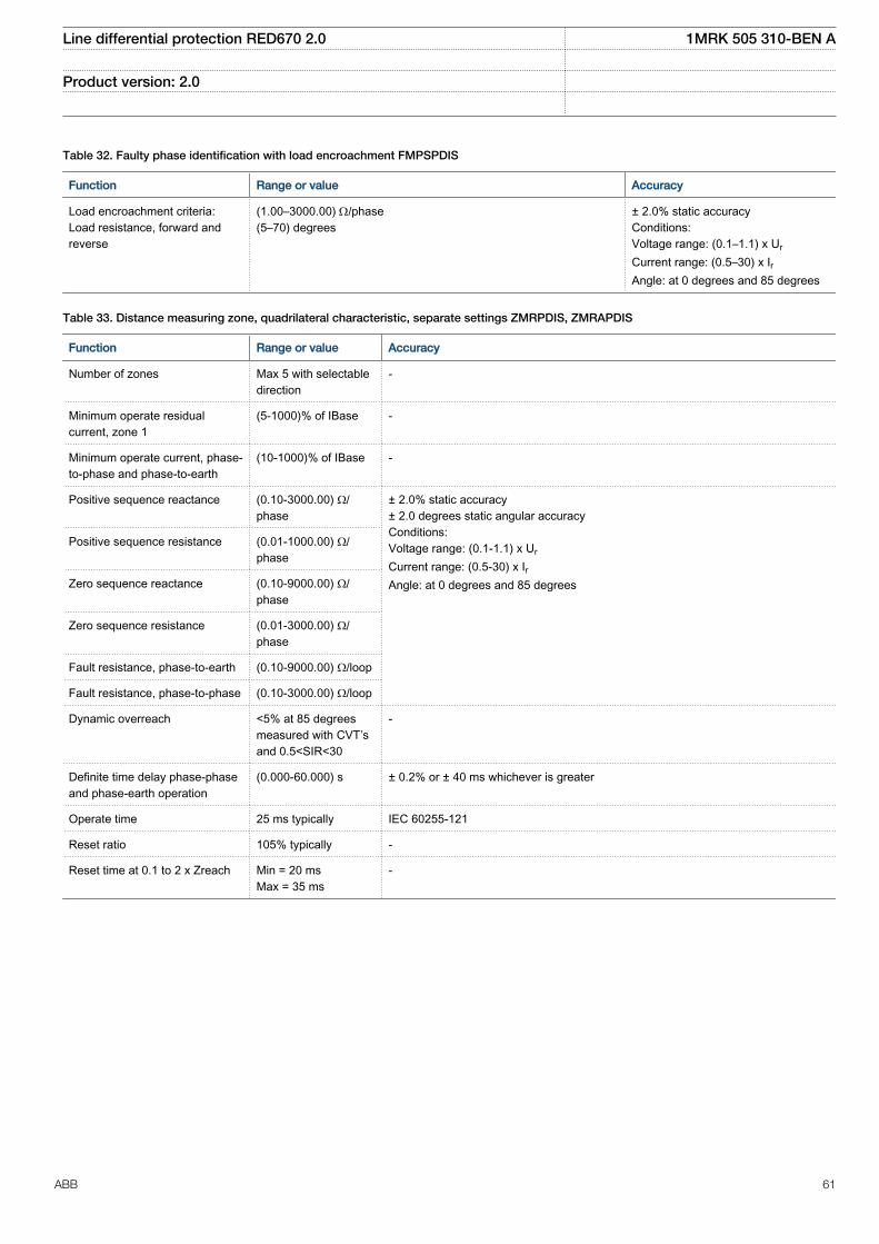
Table 32. Faulty phase identification with load encroachment FMPSPDIS
Function Range or value Accuracy
Load encroachment criteria:Load resistance, forward andreverse
(1.00–3000.00) W/phase(5–70) degrees
± 2.0% static accuracyConditions:Voltage range: (0.1–1.1) x Ur
Current range: (0.5–30) x IrAngle: at 0 degrees and 85 degrees
Table 33. Distance measuring zone, quadrilateral characteristic, separate settings ZMRPDIS, ZMRAPDIS
Function Range or value Accuracy
Number of zones Max 5 with selectabledirection
-
Minimum operate residualcurrent, zone 1
(5-1000)% of IBase -
Minimum operate current, phase-to-phase and phase-to-earth
(10-1000)% of IBase -
Positive sequence reactance (0.10-3000.00) Ω/phase
± 2.0% static accuracy± 2.0 degrees static angular accuracyConditions:Voltage range: (0.1-1.1) x Ur
Current range: (0.5-30) x IrAngle: at 0 degrees and 85 degrees
Positive sequence resistance (0.01-1000.00) Ω/phase
Zero sequence reactance (0.10-9000.00) Ω/phase
Zero sequence resistance (0.01-3000.00) Ω/phase
Fault resistance, phase-to-earth (0.10-9000.00) Ω/loop
Fault resistance, phase-to-phase (0.10-3000.00) Ω/loop
Dynamic overreach <5% at 85 degreesmeasured with CVT’sand 0.5<SIR<30
-
Definite time delay phase-phaseand phase-earth operation
(0.000-60.000) s ± 0.2% or ± 40 ms whichever is greater
Operate time 25 ms typically IEC 60255-121
Reset ratio 105% typically -
Reset time at 0.1 to 2 x Zreach Min = 20 msMax = 35 ms
-
Line differential protection RED670 2.0 1MRK 505 310-BEN A
Product version: 2.0
ABB 61
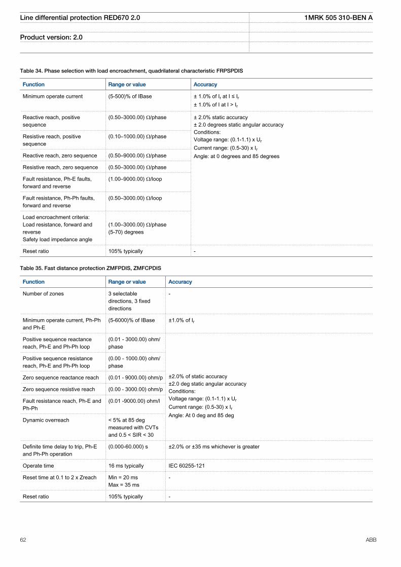
Table 34. Phase selection with load encroachment, quadrilateral characteristic FRPSPDIS
Function Range or value Accuracy
Minimum operate current (5-500)% of IBase ± 1.0% of Ir at I ≤ Ir± 1.0% of I at I > Ir
Reactive reach, positivesequence
(0.50–3000.00) Ω/phase ± 2.0% static accuracy± 2.0 degrees static angular accuracyConditions:Voltage range: (0.1-1.1) x Ur
Current range: (0.5-30) x IrAngle: at 0 degrees and 85 degrees
Resistive reach, positivesequence
(0.10–1000.00) Ω/phase
Reactive reach, zero sequence (0.50–9000.00) Ω/phase
Resistive reach, zero sequence (0.50–3000.00) Ω/phase
Fault resistance, Ph-E faults,forward and reverse
(1.00–9000.00) Ω/loop
Fault resistance, Ph-Ph faults,forward and reverse
(0.50–3000.00) Ω/loop
Load encroachment criteria:Load resistance, forward andreverseSafety load impedance angle
(1.00–3000.00) Ω/phase(5-70) degrees
Reset ratio 105% typically -
Table 35. Fast distance protection ZMFPDIS, ZMFCPDIS
Function Range or value Accuracy
Number of zones 3 selectabledirections, 3 fixeddirections
-
Minimum operate current, Ph-Phand Ph-E
(5-6000)% of IBase ±1.0% of Ir
Positive sequence reactancereach, Ph-E and Ph-Ph loop
(0.01 - 3000.00) ohm/phase
±2.0% of static accuracy±2.0 deg static angular accuracyConditions:Voltage range: (0.1-1.1) x Ur
Current range: (0.5-30) x IrAngle: At 0 deg and 85 deg
Positive sequence resistancereach, Ph-E and Ph-Ph loop
(0.00 - 1000.00) ohm/phase
Zero sequence reactance reach (0.01 - 9000.00) ohm/p
Zero sequence resistive reach (0.00 - 3000.00) ohm/p
Fault resistance reach, Ph-E andPh-Ph
(0.01 -9000.00) ohm/l
Dynamic overreach < 5% at 85 degmeasured with CVTsand 0.5 < SIR < 30
Definite time delay to trip, Ph-Eand Ph-Ph operation
(0.000-60.000) s ±2.0% or ±35 ms whichever is greater
Operate time 16 ms typically IEC 60255-121
Reset time at 0.1 to 2 x Zreach Min = 20 msMax = 35 ms
-
Reset ratio 105% typically -
Line differential protection RED670 2.0 1MRK 505 310-BEN A
Product version: 2.0
62 ABB
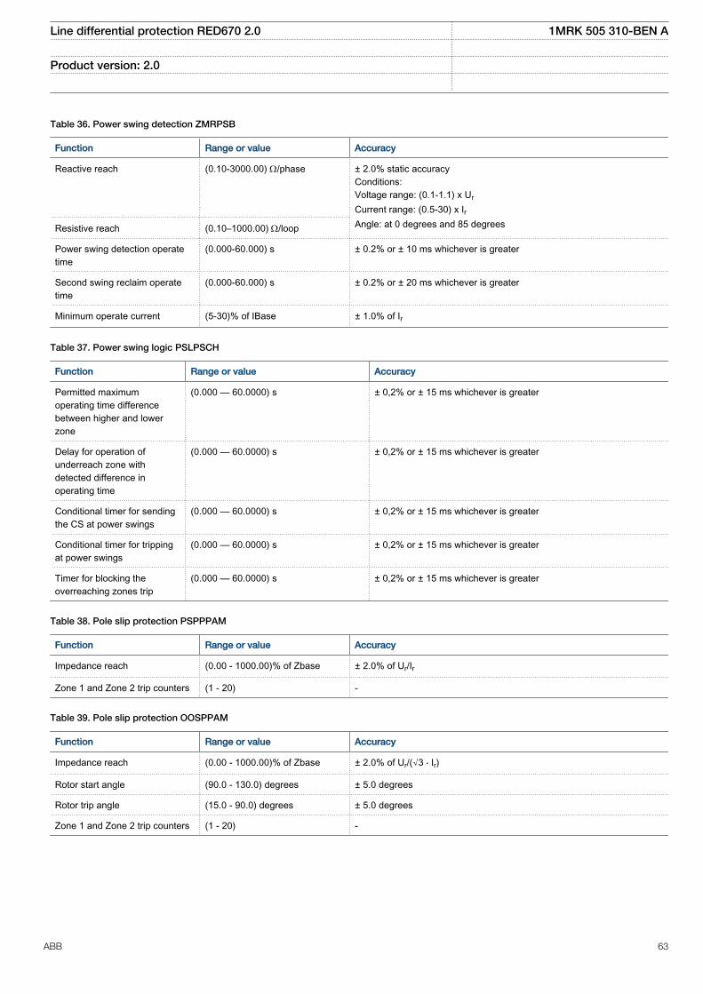
Table 36. Power swing detection ZMRPSB
Function Range or value Accuracy
Reactive reach (0.10-3000.00) W/phase
± 2.0% static accuracyConditions:Voltage range: (0.1-1.1) x Ur
Current range: (0.5-30) x IrAngle: at 0 degrees and 85 degreesResistive reach (0.10–1000.00) W/loop
Power swing detection operatetime
(0.000-60.000) s ± 0.2% or ± 10 ms whichever is greater
Second swing reclaim operatetime
(0.000-60.000) s ± 0.2% or ± 20 ms whichever is greater
Minimum operate current (5-30)% of IBase ± 1.0% of Ir
Table 37. Power swing logic PSLPSCH
Function Range or value Accuracy
Permitted maximumoperating time differencebetween higher and lowerzone
(0.000 — 60.0000) s ± 0,2% or ± 15 ms whichever is greater
Delay for operation ofunderreach zone withdetected difference inoperating time
(0.000 — 60.0000) s ± 0,2% or ± 15 ms whichever is greater
Conditional timer for sendingthe CS at power swings
(0.000 — 60.0000) s ± 0,2% or ± 15 ms whichever is greater
Conditional timer for trippingat power swings
(0.000 — 60.0000) s ± 0,2% or ± 15 ms whichever is greater
Timer for blocking theoverreaching zones trip
(0.000 — 60.0000) s ± 0,2% or ± 15 ms whichever is greater
Table 38. Pole slip protection PSPPPAM
Function Range or value Accuracy
Impedance reach (0.00 - 1000.00)% of Zbase ± 2.0% of Ur/Ir
Zone 1 and Zone 2 trip counters (1 - 20) -
Table 39. Pole slip protection OOSPPAM
Function Range or value Accuracy
Impedance reach (0.00 - 1000.00)% of Zbase ± 2.0% of Ur/(√3 ⋅ Ir)
Rotor start angle (90.0 - 130.0) degrees ± 5.0 degrees
Rotor trip angle (15.0 - 90.0) degrees ± 5.0 degrees
Zone 1 and Zone 2 trip counters (1 - 20) -
Line differential protection RED670 2.0 1MRK 505 310-BEN A
Product version: 2.0
ABB 63
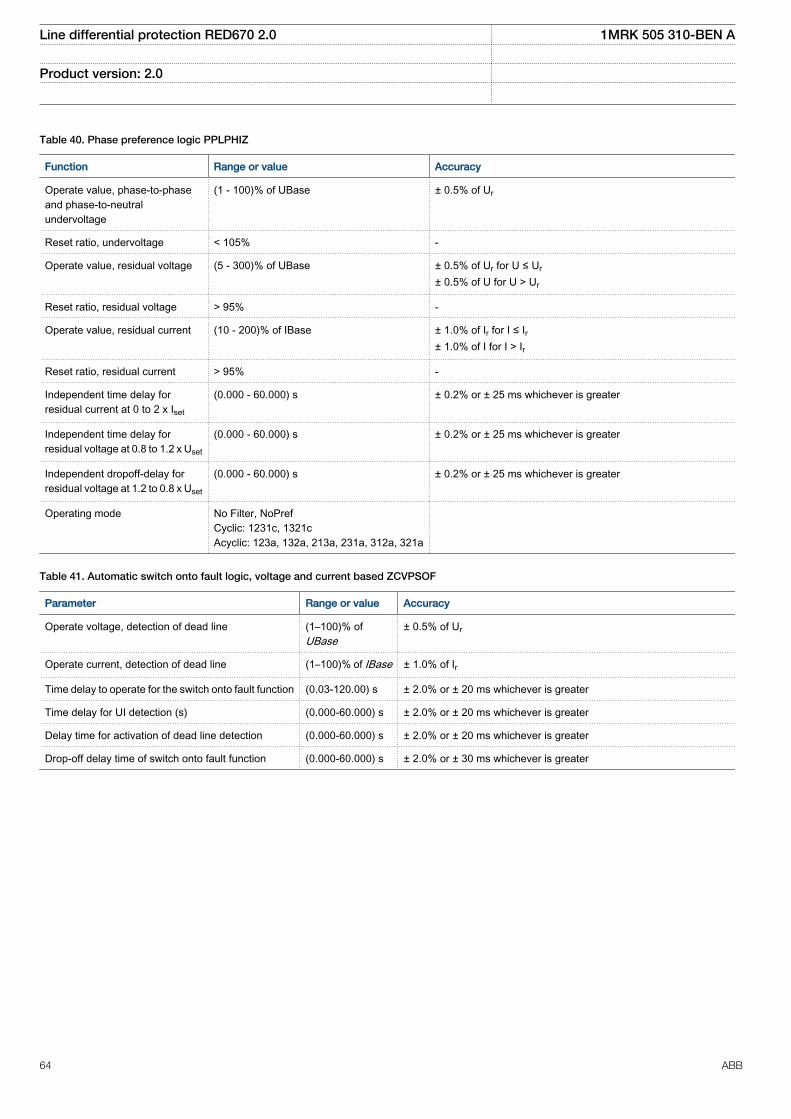
Table 40. Phase preference logic PPLPHIZ
Function Range or value Accuracy
Operate value, phase-to-phaseand phase-to-neutralundervoltage
(1 - 100)% of UBase ± 0.5% of Ur
Reset ratio, undervoltage < 105% -
Operate value, residual voltage (5 - 300)% of UBase ± 0.5% of Ur for U ≤ Ur
± 0.5% of U for U > Ur
Reset ratio, residual voltage > 95% -
Operate value, residual current (10 - 200)% of IBase ± 1.0% of Ir for I ≤ Ir± 1.0% of I for I > Ir
Reset ratio, residual current > 95% -
Independent time delay forresidual current at 0 to 2 x Iset
(0.000 - 60.000) s ± 0.2% or ± 25 ms whichever is greater
Independent time delay forresidual voltage at 0.8 to 1.2 x Uset
(0.000 - 60.000) s ± 0.2% or ± 25 ms whichever is greater
Independent dropoff-delay forresidual voltage at 1.2 to 0.8 x Uset
(0.000 - 60.000) s ± 0.2% or ± 25 ms whichever is greater
Operating mode No Filter, NoPrefCyclic: 1231c, 1321cAcyclic: 123a, 132a, 213a, 231a, 312a, 321a
Table 41. Automatic switch onto fault logic, voltage and current based ZCVPSOF
Parameter Range or value Accuracy
Operate voltage, detection of dead line (1–100)% ofUBase
± 0.5% of Ur
Operate current, detection of dead line (1–100)% of IBase ± 1.0% of Ir
Time delay to operate for the switch onto fault function (0.03-120.00) s ± 2.0% or ± 20 ms whichever is greater
Time delay for UI detection (s) (0.000-60.000) s ± 2.0% or ± 20 ms whichever is greater
Delay time for activation of dead line detection (0.000-60.000) s ± 2.0% or ± 20 ms whichever is greater
Drop-off delay time of switch onto fault function (0.000-60.000) s ± 2.0% or ± 30 ms whichever is greater
Line differential protection RED670 2.0 1MRK 505 310-BEN A
Product version: 2.0
64 ABB
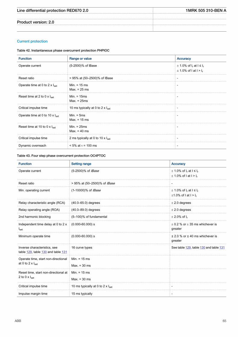
Current protection
Table 42. Instantaneous phase overcurrent protection PHPIOC
Function Range or value Accuracy
Operate current (5-2500)% of lBase ± 1.0% of Ir at I ≤ Ir± 1.0% of I at I > Ir
Reset ratio > 95% at (50–2500)% of IBase -
Operate time at 0 to 2 x Iset Min. = 15 msMax. = 25 ms
-
Reset time at 2 to 0 x Iset Min. = 15msMax. = 25ms
-
Critical impulse time 10 ms typically at 0 to 2 x Iset -
Operate time at 0 to 10 x Iset Min. = 5msMax. = 15 ms
-
Reset time at 10 to 0 x Iset Min. = 25msMax. = 40 ms
-
Critical impulse time 2 ms typically at 0 to 10 x Iset -
Dynamic overreach < 5% at t = 100 ms -
Table 43. Four step phase overcurrent protection OC4PTOC
Function Setting range Accuracy
Operate current (5-2500)% of lBase ± 1.0% of Ir at I ≤ Ir± 1.0% of I at I > Ir
Reset ratio > 95% at (50–2500)% of lBase -
Min. operating current (1-10000)% of lBase ± 1.0% of Ir at I ≤ Ir±1.0% of I at I > Ir
Relay characteristic angle (RCA) (40.0–65.0) degrees ± 2.0 degrees
Relay operating angle (ROA) (40.0–89.0) degrees ± 2.0 degrees
2nd harmonic blocking (5–100)% of fundamental ± 2.0% of Ir
Independent time delay at 0 to 2 xIset
(0.000-60.000) s ± 0.2 % or ± 35 ms whichever isgreater
Minimum operate time (0.000-60.000) s ± 2.0 % or ± 40 ms whichever isgreater
Inverse characteristics, seetable 129, table 130 and table 131
16 curve types See table 129, table 130 and table 131
Operate time, start non-directionalat 0 to 2 x Iset
Min. = 15 ms
Max. = 30 ms
Reset time, start non-directional at2 to 0 x Iset
Min. = 15 ms
Max. = 30 ms
Critical impulse time 10 ms typically at 0 to 2 x Iset -
Impulse margin time 15 ms typically -
Line differential protection RED670 2.0 1MRK 505 310-BEN A
Product version: 2.0
ABB 65
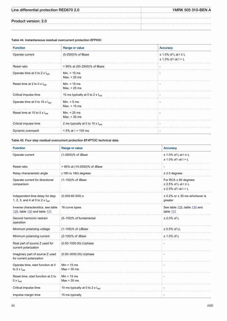
Table 44. Instantaneous residual overcurrent protection EFPIOC
Function Range or value Accuracy
Operate current (5-2500)% of lBase ± 1.0% of Ir at I ≤ Ir± 1.0% of I at I > Ir
Reset ratio > 95% at (50–2500)% of lBase -
Operate time at 0 to 2 x Iset Min. = 15 msMax. = 25 ms
-
Reset time at 2 to 0 x Iset Min. = 15 msMax. = 25 ms
-
Critical impulse time 10 ms typically at 0 to 2 x Iset -
Operate time at 0 to 10 x Iset Min. = 5 msMax. = 15 ms
-
Reset time at 10 to 0 x Iset Min. = 25 msMax. = 35 ms
-
Critical impulse time 2 ms typically at 0 to 10 x Iset -
Dynamic overreach < 5% at t = 100 ms -
Table 45. Four step residual overcurrent protection EF4PTOC technical data
Function Range or value Accuracy
Operate current (1-2500)% of lBase ± 1.0% of Ir at I ≤ Ir± 1.0% of I at I > Ir
Reset ratio > 95% at (10-2500)% of lBase -
Relay characteristic angle (-180 to 180) degrees ± 2.0 degrees
Operate current for directionalcomparison
(1–100)% of lBase For RCA ± 60 degrees:± 2.5% of Ir at I ≤ Ir± 2.5% of I at I > Ir
Independent time delay for step1, 2, 3, and 4 at 0 to 2 x Iset
(0.000-60.000) s ± 0.2% or ± 35 ms whichever isgreater
Inverse characteristics, see table129, table 130 and table 131
16 curve types See table 129, table 130 andtable 131
Second harmonic restrainoperation
(5–100)% of fundamental ± 2.0% of Ir
Minimum polarizing voltage (1–100)% of UBase ± 0.5% of Ur
Minimum polarizing current (2-100)% of IBase ± 1.0% of Ir
Real part of source Z used forcurrent polarization
(0.50-1000.00) W/phase -
Imaginary part of source Z usedfor current polarization
(0.50–3000.00) W/phase -
Operate time, start function at 0to 2 x Iset
Min = 15 msMax = 30 ms
-
Reset time, start function at 2 to0 x Iset
Min = 15 msMax = 30 ms
-
Critical impulse time 10 ms typically at 0 to 2 x Iset -
Impulse margin time 15 ms typically -
Line differential protection RED670 2.0 1MRK 505 310-BEN A
Product version: 2.0
66 ABB
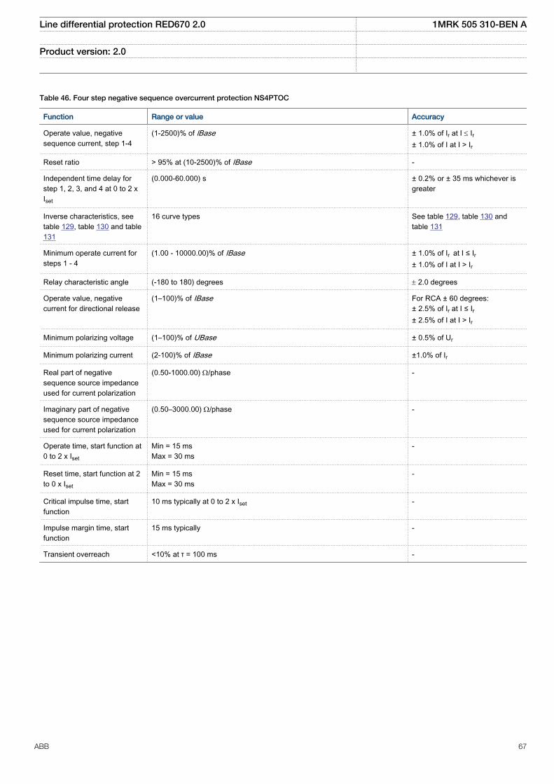
Table 46. Four step negative sequence overcurrent protection NS4PTOC
Function Range or value Accuracy
Operate value, negativesequence current, step 1-4
(1-2500)% of lBase ± 1.0% of Ir at I £ Ir± 1.0% of I at I > Ir
Reset ratio > 95% at (10-2500)% of IBase -
Independent time delay forstep 1, 2, 3, and 4 at 0 to 2 xIset
(0.000-60.000) s ± 0.2% or ± 35 ms whichever isgreater
Inverse characteristics, seetable 129, table 130 and table131
16 curve types See table 129, table 130 andtable 131
Minimum operate current forsteps 1 - 4
(1.00 - 10000.00)% of IBase ± 1.0% of Ir at I ≤ Ir± 1.0% of I at I > Ir
Relay characteristic angle (-180 to 180) degrees ± 2.0 degrees
Operate value, negativecurrent for directional release
(1–100)% of IBase For RCA ± 60 degrees:± 2.5% of Ir at I ≤ Ir± 2.5% of I at I > Ir
Minimum polarizing voltage (1–100)% of UBase ± 0.5% of Ur
Minimum polarizing current (2-100)% of IBase ±1.0% of Ir
Real part of negativesequence source impedanceused for current polarization
(0.50-1000.00) W/phase -
Imaginary part of negativesequence source impedanceused for current polarization
(0.50–3000.00) W/phase -
Operate time, start function at0 to 2 x Iset
Min = 15 msMax = 30 ms
-
Reset time, start function at 2to 0 x Iset
Min = 15 msMax = 30 ms
-
Critical impulse time, startfunction
10 ms typically at 0 to 2 x Iset -
Impulse margin time, startfunction
15 ms typically -
Transient overreach <10% at τ = 100 ms -
Line differential protection RED670 2.0 1MRK 505 310-BEN A
Product version: 2.0
ABB 67
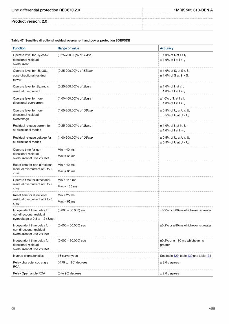
Table 47. Sensitive directional residual overcurrent and power protection SDEPSDE
Function Range or value Accuracy
Operate level for 3I0·cosj
directional residualovercurrent
(0.25-200.00)% of lBase ± 1.0% of Ir at I £ Ir± 1.0% of I at I > Ir
Operate level for ·3I0·3U0
cosj directional residualpower
(0.25-200.00)% of SBase ± 1.0% of Sr at S £ Sr
± 1.0% of S at S > Sr
Operate level for 3I0 and jresidual overcurrent
(0.25-200.00)% of lBase ± 1.0% of Ir at £ Ir± 1.0% of I at I > Ir
Operate level for non-directional overcurrent
(1.00-400.00)% of lBase ±1.0% of Ir at I £ Ir± 1.0% of I at I > Ir
Operate level for non-directional residualovervoltage
(1.00-200.00)% of UBase ± 0.5% of Ur at U £ Ur
± 0.5% of U at U > Ur
Residual release current forall directional modes
(0.25-200.00)% of lBase ± 1.0% of Ir at I £ Ir± 1.0% of I at I > Ir
Residual release voltage forall directional modes
(1.00-300.00)% of UBase ± 0.5% of Ur at U £ Ur
± 0.5% of U at U > Ur
Operate time for non-directional residualovercurrent at 0 to 2 x Iset
Min = 40 ms
Max = 65 ms
Reset time for non-directionalresidual overcurrent at 2 to 0x Iset
Min = 40 ms
Max = 65 ms
Operate time for directionalresidual overcurrent at 0 to 2x Iset
Min = 115 ms
Max = 165 ms
Reset time for directionalresidual overcurrent at 2 to 0x Iset
Min = 25 ms
Max = 65 ms
Independent time delay fornon-directional residualovervoltage at 0.8 to 1.2 x Uset
(0.000 – 60.000) sec ±0.2% or ± 80 ms whichever is greater
Independent time delay fornon-directional residualovercurrent at 0 to 2 x Iset
(0.000 – 60.000) sec ±0.2% or ± 80 ms whichever is greater
Independent time delay fordirectional residualovercurrent at 0 to 2 x Iset
(0.000 – 60.000) sec ±0.2% or ± 180 ms whichever isgreater
Inverse characteristics 16 curve types See table 129, table 130 and table 131
Relay characteristic angleRCA
(-179 to 180) degrees ± 2.0 degrees
Relay Open angle ROA (0 to 90) degrees ± 2.0 degrees
Line differential protection RED670 2.0 1MRK 505 310-BEN A
Product version: 2.0
68 ABB
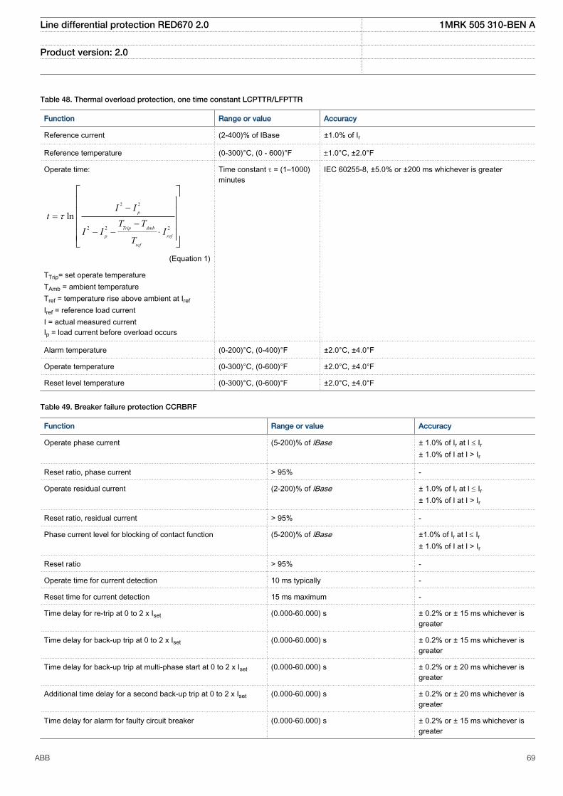
Table 48. Thermal overload protection, one time constant LCPTTR/LFPTTR
Function Range or value Accuracy
Reference current (2-400)% of IBase ±1.0% of Ir
Reference temperature (0-300)°C, (0 - 600)°F ±1.0°C, ±2.0°F
Operate time:
2 2
2 2 2
ln p
Trip Amb
p ref
ref
I It
T TI I I
T
t-
=-
- - ×
é ùê úê úê úê úë û
EQUATION13000039 V2 EN (Equation 1)
TTrip= set operate temperatureTAmb = ambient temperatureTref = temperature rise above ambient at Iref
Iref = reference load currentI = actual measured currentIp = load current before overload occurs
Time constant t = (1–1000)minutes
IEC 60255-8, ±5.0% or ±200 ms whichever is greater
Alarm temperature (0-200)°C, (0-400)°F ±2.0°C, ±4.0°F
Operate temperature (0-300)°C, (0-600)°F ±2.0°C, ±4.0°F
Reset level temperature (0-300)°C, (0-600)°F ±2.0°C, ±4.0°F
Table 49. Breaker failure protection CCRBRF
Function Range or value Accuracy
Operate phase current (5-200)% of lBase ± 1.0% of Ir at I £ Ir± 1.0% of I at I > Ir
Reset ratio, phase current > 95% -
Operate residual current (2-200)% of lBase ± 1.0% of Ir at I £ Ir± 1.0% of I at I > Ir
Reset ratio, residual current > 95% -
Phase current level for blocking of contact function (5-200)% of lBase ±1.0% of Ir at I £ Ir± 1.0% of I at I > Ir
Reset ratio > 95% -
Operate time for current detection 10 ms typically -
Reset time for current detection 15 ms maximum -
Time delay for re-trip at 0 to 2 x Iset (0.000-60.000) s ± 0.2% or ± 15 ms whichever isgreater
Time delay for back-up trip at 0 to 2 x Iset (0.000-60.000) s ± 0.2% or ± 15 ms whichever isgreater
Time delay for back-up trip at multi-phase start at 0 to 2 x Iset (0.000-60.000) s ± 0.2% or ± 20 ms whichever isgreater
Additional time delay for a second back-up trip at 0 to 2 x Iset (0.000-60.000) s ± 0.2% or ± 20 ms whichever isgreater
Time delay for alarm for faulty circuit breaker (0.000-60.000) s ± 0.2% or ± 15 ms whichever isgreater
Line differential protection RED670 2.0 1MRK 505 310-BEN A
Product version: 2.0
ABB 69
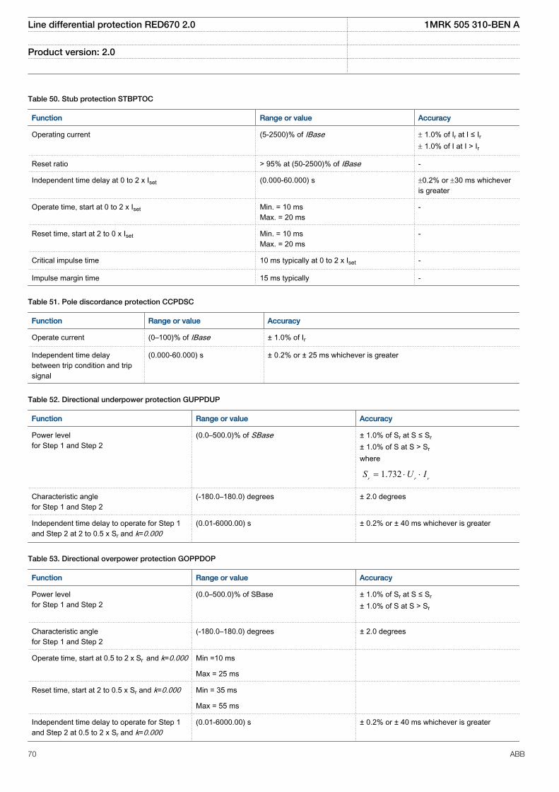
Table 50. Stub protection STBPTOC
Function Range or value Accuracy
Operating current (5-2500)% of IBase ± 1.0% of Ir at I ≤ Ir± 1.0% of I at I > Ir
Reset ratio > 95% at (50-2500)% of IBase -
Independent time delay at 0 to 2 x Iset (0.000-60.000) s ±0.2% or ±30 ms whicheveris greater
Operate time, start at 0 to 2 x Iset Min. = 10 msMax. = 20 ms
-
Reset time, start at 2 to 0 x Iset Min. = 10 msMax. = 20 ms
-
Critical impulse time 10 ms typically at 0 to 2 x Iset -
Impulse margin time 15 ms typically -
Table 51. Pole discordance protection CCPDSC
Function Range or value Accuracy
Operate current (0–100)% of IBase ± 1.0% of Ir
Independent time delaybetween trip condition and tripsignal
(0.000-60.000) s ± 0.2% or ± 25 ms whichever is greater
Table 52. Directional underpower protection GUPPDUP
Function Range or value Accuracy
Power levelfor Step 1 and Step 2
(0.0–500.0)% of SBase ± 1.0% of Sr at S ≤ Sr
± 1.0% of S at S > Sr
where
1.732r r rS U I= × ×
Characteristic anglefor Step 1 and Step 2
(-180.0–180.0) degrees ± 2.0 degrees
Independent time delay to operate for Step 1and Step 2 at 2 to 0.5 x Sr and k=0.000
(0.01-6000.00) s ± 0.2% or ± 40 ms whichever is greater
Table 53. Directional overpower protection GOPPDOP
Function Range or value Accuracy
Power levelfor Step 1 and Step 2
(0.0–500.0)% of SBase
± 1.0% of Sr at S ≤ Sr
± 1.0% of S at S > Sr
Characteristic anglefor Step 1 and Step 2
(-180.0–180.0) degrees ± 2.0 degrees
Operate time, start at 0.5 to 2 x Sr and k=0.000 Min =10 ms
Max = 25 ms
Reset time, start at 2 to 0.5 x Sr and k=0.000 Min = 35 ms
Max = 55 ms
Independent time delay to operate for Step 1and Step 2 at 0.5 to 2 x Sr and k=0.000
(0.01-6000.00) s ± 0.2% or ± 40 ms whichever is greater
Line differential protection RED670 2.0 1MRK 505 310-BEN A
Product version: 2.0
70 ABB
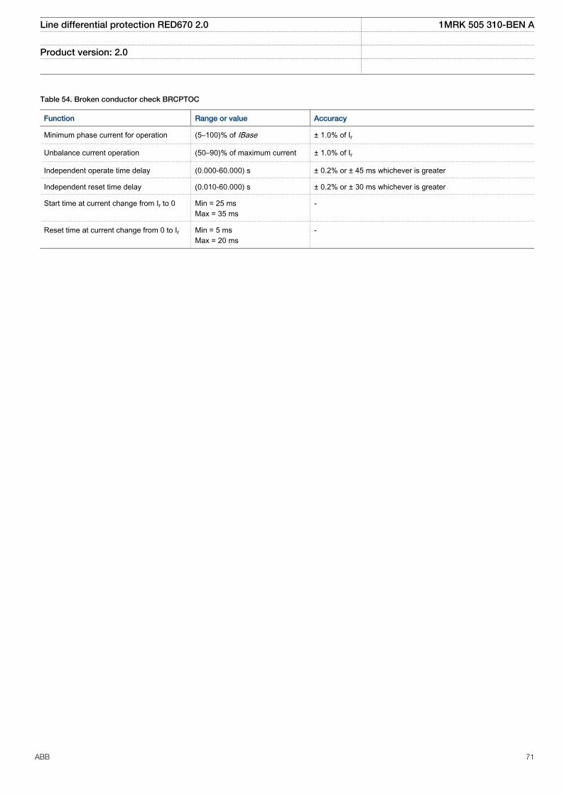
Table 54. Broken conductor check BRCPTOC
Function Range or value Accuracy
Minimum phase current for operation (5–100)% of IBase ± 1.0% of Ir
Unbalance current operation (50–90)% of maximum current ± 1.0% of Ir
Independent operate time delay (0.000-60.000) s ± 0.2% or ± 45 ms whichever is greater
Independent reset time delay (0.010-60.000) s ± 0.2% or ± 30 ms whichever is greater
Start time at current change from Ir to 0 Min = 25 msMax = 35 ms
-
Reset time at current change from 0 to Ir Min = 5 msMax = 20 ms
-
Line differential protection RED670 2.0 1MRK 505 310-BEN A
Product version: 2.0
ABB 71
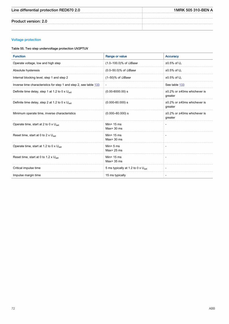
Voltage protection
Table 55. Two step undervoltage protection UV2PTUV
Function Range or value Accuracy
Operate voltage, low and high step (1.0–100.0)% of UBase ±0.5% of Ur
Absolute hysteresis (0.0–50.0)% of UBase ±0.5% of Ur
Internal blocking level, step 1 and step 2 (1–50)% of UBase ±0.5% of Ur
Inverse time characteristics for step 1 and step 2, see table 133 - See table 133
Definite time delay, step 1 at 1.2 to 0 x Uset (0.00-6000.00) s ±0.2% or ±40ms whichever isgreater
Definite time delay, step 2 at 1.2 to 0 x Uset (0.000-60.000) s ±0.2% or ±40ms whichever isgreater
Minimum operate time, inverse characteristics (0.000–60.000) s ±0.2% or ±40ms whichever isgreater
Operate time, start at 2 to 0 x Uset Min= 15 msMax= 30 ms
-
Reset time, start at 0 to 2 x Uset Min= 15 msMax= 30 ms
-
Operate time, start at 1.2 to 0 x Uset Min= 5 msMax= 25 ms
-
Reset time, start at 0 to 1.2 x Uset Min= 15 msMax= 35 ms
-
Critical impulse time 5 ms typically at 1.2 to 0 x Uset -
Impulse margin time 15 ms typically -
Line differential protection RED670 2.0 1MRK 505 310-BEN A
Product version: 2.0
72 ABB
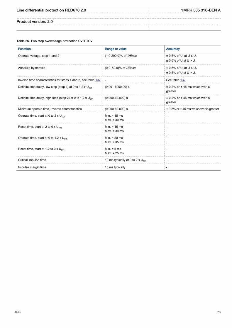
Table 56. Two step overvoltage protection OV2PTOV
Function Range or value Accuracy
Operate voltage, step 1 and 2 (1.0-200.0)% of UBase ± 0.5% of Ur at U ≤ Ur
± 0.5% of U at U > Ur
Absolute hysteresis (0.0–50.0)% of UBase ± 0.5% of Ur at U ≤ Ur
± 0.5% of U at U > Ur
Inverse time characteristics for steps 1 and 2, see table 132 - See table 132
Definite time delay, low step (step 1) at 0 to 1.2 x Uset (0.00 - 6000.00) s ± 0.2% or ± 45 ms whichever isgreater
Definite time delay, high step (step 2) at 0 to 1.2 x Uset (0.000-60.000) s ± 0.2% or ± 45 ms whichever isgreater
Minimum operate time, Inverse characteristics (0.000-60.000) s ± 0.2% or ± 45 ms whichever is greater
Operate time, start at 0 to 2 x Uset Min. = 15 msMax. = 30 ms
-
Reset time, start at 2 to 0 x Uset Min. = 15 msMax. = 30 ms
-
Operate time, start at 0 to 1.2 x Uset Min. = 20 msMax. = 35 ms
-
Reset time, start at 1.2 to 0 x Uset Min. = 5 msMax. = 25 ms
-
Critical impulse time 10 ms typically at 0 to 2 x Uset -
Impulse margin time 15 ms typically -
Line differential protection RED670 2.0 1MRK 505 310-BEN A
Product version: 2.0
ABB 73
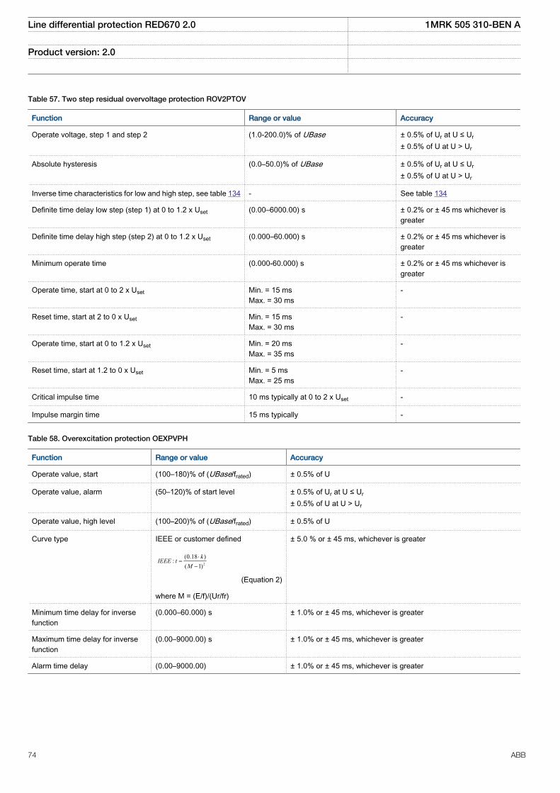
Table 57. Two step residual overvoltage protection ROV2PTOV
Function Range or value Accuracy
Operate voltage, step 1 and step 2 (1.0-200.0)% of UBase ± 0.5% of Ur at U ≤ Ur
± 0.5% of U at U > Ur
Absolute hysteresis (0.0–50.0)% of UBase ± 0.5% of Ur at U ≤ Ur
± 0.5% of U at U > Ur
Inverse time characteristics for low and high step, see table 134 - See table 134
Definite time delay low step (step 1) at 0 to 1.2 x Uset (0.00–6000.00) s ± 0.2% or ± 45 ms whichever isgreater
Definite time delay high step (step 2) at 0 to 1.2 x Uset (0.000–60.000) s ± 0.2% or ± 45 ms whichever isgreater
Minimum operate time (0.000-60.000) s ± 0.2% or ± 45 ms whichever isgreater
Operate time, start at 0 to 2 x Uset Min. = 15 msMax. = 30 ms
-
Reset time, start at 2 to 0 x Uset Min. = 15 msMax. = 30 ms
-
Operate time, start at 0 to 1.2 x Uset Min. = 20 msMax. = 35 ms
-
Reset time, start at 1.2 to 0 x Uset Min. = 5 msMax. = 25 ms
-
Critical impulse time 10 ms typically at 0 to 2 x Uset -
Impulse margin time 15 ms typically -
Table 58. Overexcitation protection OEXPVPH
Function Range or value Accuracy
Operate value, start (100–180)% of (UBase/frated) ± 0.5% of U
Operate value, alarm (50–120)% of start level ± 0.5% of Ur at U ≤ Ur
± 0.5% of U at U > Ur
Operate value, high level (100–200)% of (UBase/frated) ± 0.5% of U
Curve type IEEE or customer defined
2
(0.18 ):
( 1)k
IEEE tM
×=
-
EQUATION1319 V1 EN (Equation 2)
where M = (E/f)/(Ur/fr)
± 5.0 % or ± 45 ms, whichever is greater
Minimum time delay for inversefunction
(0.000–60.000) s ± 1.0% or ± 45 ms, whichever is greater
Maximum time delay for inversefunction
(0.00–9000.00) s ± 1.0% or ± 45 ms, whichever is greater
Alarm time delay (0.00–9000.00) ± 1.0% or ± 45 ms, whichever is greater
Line differential protection RED670 2.0 1MRK 505 310-BEN A
Product version: 2.0
74 ABB
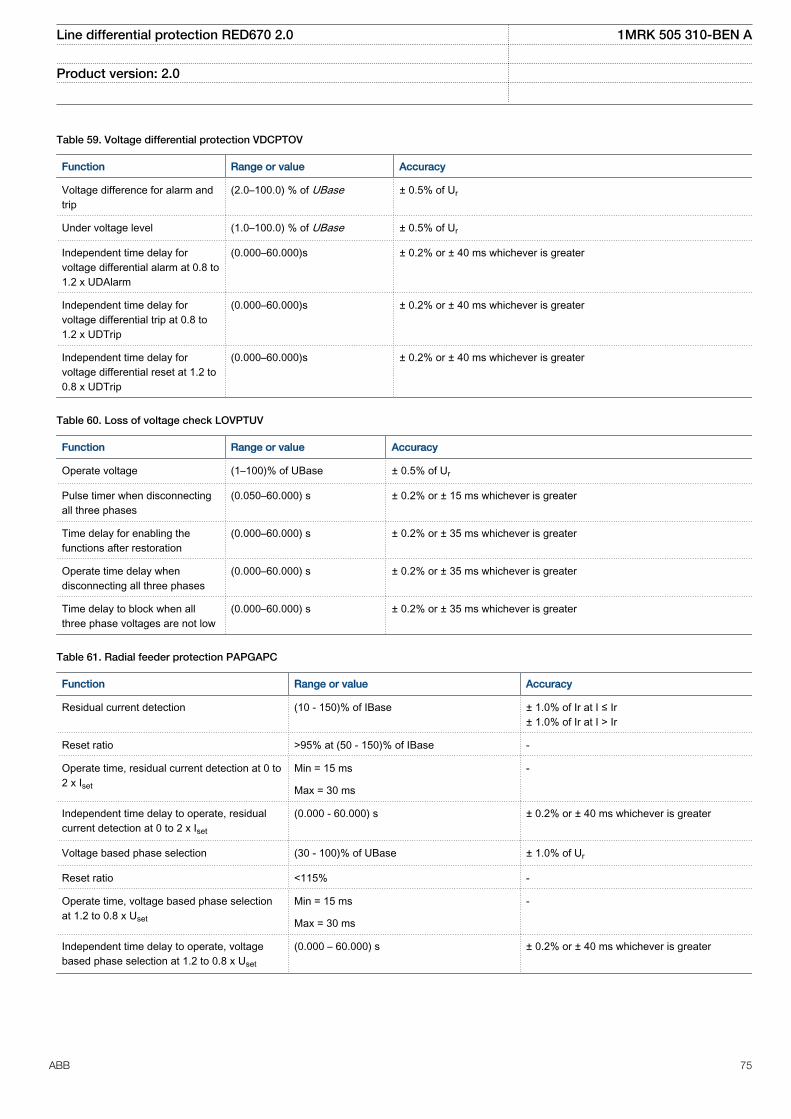
Table 59. Voltage differential protection VDCPTOV
Function Range or value Accuracy
Voltage difference for alarm andtrip
(2.0–100.0) % of UBase ± 0.5% of Ur
Under voltage level (1.0–100.0) % of UBase ± 0.5% of Ur
Independent time delay forvoltage differential alarm at 0.8 to1.2 x UDAlarm
(0.000–60.000)s ± 0.2% or ± 40 ms whichever is greater
Independent time delay forvoltage differential trip at 0.8 to1.2 x UDTrip
(0.000–60.000)s ± 0.2% or ± 40 ms whichever is greater
Independent time delay forvoltage differential reset at 1.2 to0.8 x UDTrip
(0.000–60.000)s ± 0.2% or ± 40 ms whichever is greater
Table 60. Loss of voltage check LOVPTUV
Function Range or value Accuracy
Operate voltage (1–100)% of UBase ± 0.5% of Ur
Pulse timer when disconnectingall three phases
(0.050–60.000) s ± 0.2% or ± 15 ms whichever is greater
Time delay for enabling thefunctions after restoration
(0.000–60.000) s ± 0.2% or ± 35 ms whichever is greater
Operate time delay whendisconnecting all three phases
(0.000–60.000) s ± 0.2% or ± 35 ms whichever is greater
Time delay to block when allthree phase voltages are not low
(0.000–60.000) s ± 0.2% or ± 35 ms whichever is greater
Table 61. Radial feeder protection PAPGAPC
Function Range or value Accuracy
Residual current detection (10 - 150)% of IBase ± 1.0% of Ir at I ≤ Ir± 1.0% of Ir at I > Ir
Reset ratio >95% at (50 - 150)% of IBase -
Operate time, residual current detection at 0 to2 x Iset
Min = 15 ms -
Max = 30 ms
Independent time delay to operate, residualcurrent detection at 0 to 2 x Iset
(0.000 - 60.000) s ± 0.2% or ± 40 ms whichever is greater
Voltage based phase selection (30 - 100)% of UBase ± 1.0% of Ur
Reset ratio <115% -
Operate time, voltage based phase selectionat 1.2 to 0.8 x Uset
Min = 15 ms -
Max = 30 ms
Independent time delay to operate, voltagebased phase selection at 1.2 to 0.8 x Uset
(0.000 – 60.000) s ± 0.2% or ± 40 ms whichever is greater
Line differential protection RED670 2.0 1MRK 505 310-BEN A
Product version: 2.0
ABB 75
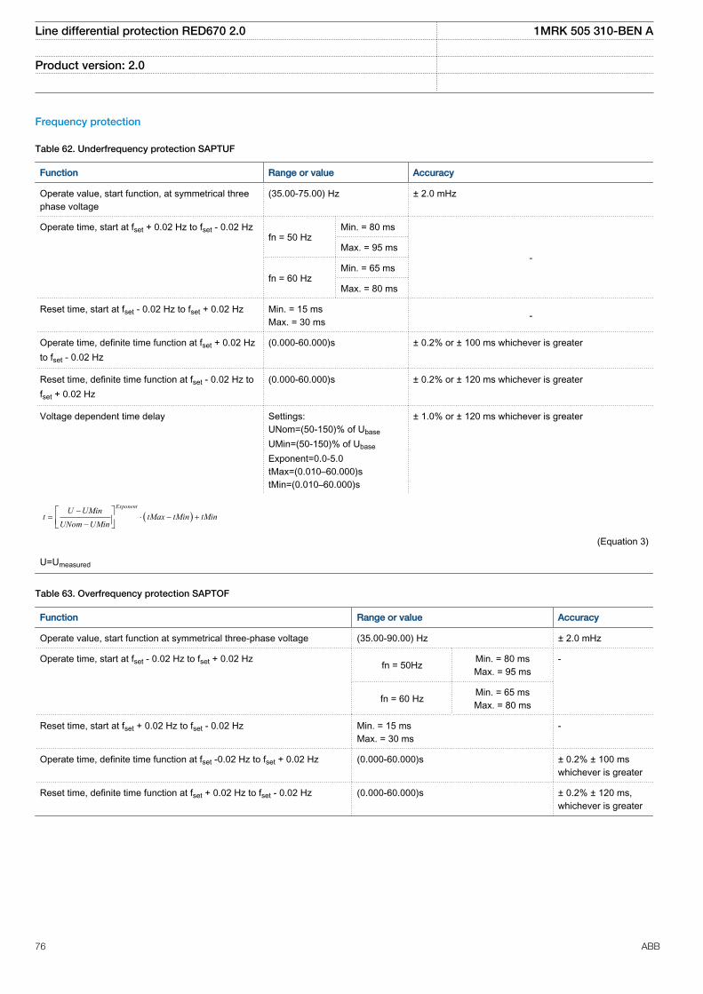
Frequency protection
Table 62. Underfrequency protection SAPTUF
Function Range or value Accuracy
Operate value, start function, at symmetrical threephase voltage
(35.00-75.00) Hz ± 2.0 mHz
Operate time, start at fset + 0.02 Hz to fset - 0.02 Hzfn = 50 Hz
Min. = 80 ms
-Max. = 95 ms
fn = 60 HzMin. = 65 ms
Max. = 80 ms
Reset time, start at fset - 0.02 Hz to fset + 0.02 Hz Min. = 15 msMax. = 30 ms -
Operate time, definite time function at fset + 0.02 Hzto fset - 0.02 Hz
(0.000-60.000)s ± 0.2% or ± 100 ms whichever is greater
Reset time, definite time function at fset - 0.02 Hz tofset + 0.02 Hz
(0.000-60.000)s ± 0.2% or ± 120 ms whichever is greater
Voltage dependent time delay Settings:UNom=(50-150)% of Ubase
UMin=(50-150)% of Ubase
Exponent=0.0-5.0tMax=(0.010–60.000)stMin=(0.010–60.000)s
± 1.0% or ± 120 ms whichever is greater
( )ExponentU UMin
t tMax tMin tMinUNom UMin
-= × - +
-é ùê úë û
EQUATION1182 V1 EN (Equation 3)
U=Umeasured
Table 63. Overfrequency protection SAPTOF
Function Range or value Accuracy
Operate value, start function at symmetrical three-phase voltage (35.00-90.00) Hz ± 2.0 mHz
Operate time, start at fset - 0.02 Hz to fset + 0.02 Hz fn = 50Hz Min. = 80 msMax. = 95 ms
-
fn = 60 Hz Min. = 65 msMax. = 80 ms
Reset time, start at fset + 0.02 Hz to fset - 0.02 Hz Min. = 15 msMax. = 30 ms
-
Operate time, definite time function at fset -0.02 Hz to fset + 0.02 Hz (0.000-60.000)s ± 0.2% ± 100 mswhichever is greater
Reset time, definite time function at fset + 0.02 Hz to fset - 0.02 Hz (0.000-60.000)s ± 0.2% ± 120 ms,whichever is greater
Line differential protection RED670 2.0 1MRK 505 310-BEN A
Product version: 2.0
76 ABB
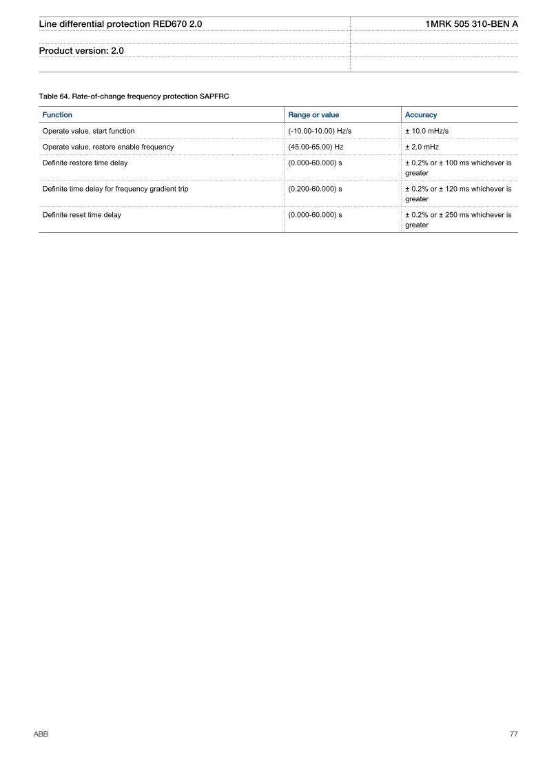
Table 64. Rate-of-change frequency protection SAPFRC
Function Range or value Accuracy
Operate value, start function (-10.00-10.00) Hz/s ± 10.0 mHz/s
Operate value, restore enable frequency (45.00-65.00) Hz ± 2.0 mHz
Definite restore time delay (0.000-60.000) s ± 0.2% or ± 100 ms whichever isgreater
Definite time delay for frequency gradient trip (0.200-60.000) s ± 0.2% or ± 120 ms whichever isgreater
Definite reset time delay (0.000-60.000) s ± 0.2% or ± 250 ms whichever isgreater
Line differential protection RED670 2.0 1MRK 505 310-BEN A
Product version: 2.0
ABB 77
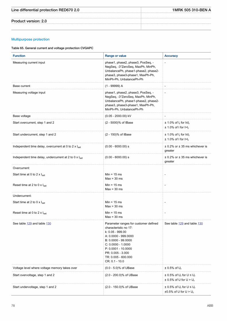
Multipurpose protection
Table 65. General current and voltage protection CVGAPC
Function Range or value Accuracy
Measuring current input phase1, phase2, phase3, PosSeq, -NegSeq, -3*ZeroSeq, MaxPh, MinPh,UnbalancePh, phase1-phase2, phase2-phase3, phase3-phase1, MaxPh-Ph,MinPh-Ph, UnbalancePh-Ph
-
Base current (1 - 99999) A -
Measuring voltage input phase1, phase2, phase3, PosSeq, -NegSeq, -3*ZeroSeq, MaxPh, MinPh,UnbalancePh, phase1-phase2, phase2-phase3, phase3-phase1, MaxPh-Ph,MinPh-Ph, UnbalancePh-Ph
-
Base voltage (0.05 - 2000.00) kV -
Start overcurrent, step 1 and 2 (2 - 5000)% of IBase ± 1.0% of Ir for I≤Ir± 1.0% of I for I>Ir
Start undercurrent, step 1 and 2 (2 - 150)% of IBase ± 1.0% of Ir for I≤Ir± 1.0% of I for I>Ir
Independent time delay, overcurrent at 0 to 2 x Iset (0.00 - 6000.00) s ± 0.2% or ± 35 ms whichever isgreater
Independent time delay, undercurrent at 2 to 0 x Iset (0.00 - 6000.00) s ± 0.2% or ± 35 ms whichever isgreater
Overcurrent:
Start time at 0 to 2 x Iset Min = 15 msMax = 30 ms
-
Reset time at 2 to 0 x Iset Min = 15 msMax = 30 ms
-
Undercurrent:
Start time at 2 to 0 x Iset Min = 15 msMax = 30 ms
-
Reset time at 0 to 2 x Iset Min = 15 msMax = 30 ms
-
See table 129 and table 130 Parameter ranges for customer definedcharacteristic no 17:k: 0.05 - 999.00A: 0.0000 - 999.0000B: 0.0000 - 99.0000C: 0.0000 - 1.0000P: 0.0001 - 10.0000PR: 0.005 - 3.000TR: 0.005 - 600.000CR: 0.1 - 10.0
See table 129 and table 130
Voltage level where voltage memory takes over (0.0 - 5.0)% of UBase ± 0.5% of Ur
Start overvoltage, step 1 and 2 (2.0 - 200.0)% of UBase ± 0.5% of Ur for U ≤ Ur
± 0.5% of U for U > Ur
Start undervoltage, step 1 and 2 (2.0 - 150.0)% of UBase ± 0.5% of Ur for U ≤ Ur
±0.5% of U for U > Ur
Line differential protection RED670 2.0 1MRK 505 310-BEN A
Product version: 2.0
78 ABB
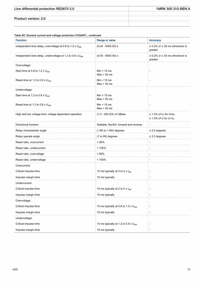
Table 65. General current and voltage protection CVGAPC , continued
Function Range or value Accuracy
Independent time delay, overvoltage at 0.8 to 1.2 x Uset (0.00 - 6000.00) s ± 0.2% or ± 35 ms whichever isgreater
Independent time delay, undervoltage at 1.2 to 0.8 x Uset (0.00 - 6000.00) s ± 0.2% or ± 35 ms whichever isgreater
Overvoltage:
Start time at 0.8 to 1.2 x Uset Min = 15 msMax = 30 ms
-
Reset time at 1.2 to 0.8 x Uset Min = 15 msMax = 30 ms
-
Undervoltage:
Start time at 1.2 to 0.8 x Uset Min = 15 msMax = 30 ms
-
Reset time at 1.2 to 0.8 x Uset Min = 15 msMax = 30 ms
-
High and low voltage limit, voltage dependent operation (1.0 - 200.0)% of UBase ± 1.0% of Ur for U≤Ur
± 1.0% of U for U>Ur
Directional function Settable: NonDir, forward and reverse -
Relay characteristic angle (-180 to +180) degrees ± 2.0 degrees
Relay operate angle (1 to 90) degrees ± 2.0 degrees
Reset ratio, overcurrent > 95% -
Reset ratio, undercurrent < 105% -
Reset ratio, overvoltage > 95% -
Reset ratio, undervoltage < 105% -
Overcurrent:
Critical impulse time 10 ms typically at 0 to 2 x Iset -
Impulse margin time 15 ms typically -
Undercurrent:
Critical impulse time 10 ms typically at 2 to 0 x Iset -
Impulse margin time 15 ms typically -
Overvoltage:
Critical impulse time 10 ms typically at 0.8 to 1.2 x Uset -
Impulse margin time 15 ms typically -
Undervoltage:
Critical impulse time 10 ms typically at 1.2 to 0.8 x Uset -
Impulse margin time 15 ms typically -
Line differential protection RED670 2.0 1MRK 505 310-BEN A
Product version: 2.0
ABB 79
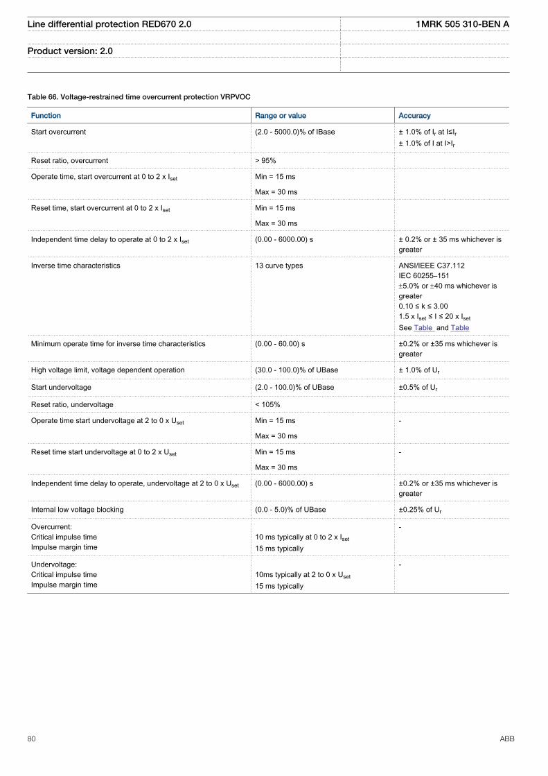
Table 66. Voltage-restrained time overcurrent protection VRPVOC
Function Range or value Accuracy
Start overcurrent (2.0 - 5000.0)% of IBase ± 1.0% of Ir at I≤Ir± 1.0% of I at I>Ir
Reset ratio, overcurrent > 95%
Operate time, start overcurrent at 0 to 2 x Iset Min = 15 ms
Max = 30 ms
Reset time, start overcurrent at 0 to 2 x Iset Min = 15 ms
Max = 30 ms
Independent time delay to operate at 0 to 2 x Iset (0.00 - 6000.00) s ± 0.2% or ± 35 ms whichever isgreater
Inverse time characteristics 13 curve types ANSI/IEEE C37.112IEC 60255–151±5.0% or ±40 ms whichever isgreater0.10 ≤ k ≤ 3.001.5 x Iset ≤ I ≤ 20 x Iset
See Table and Table
Minimum operate time for inverse time characteristics (0.00 - 60.00) s ±0.2% or ±35 ms whichever isgreater
High voltage limit, voltage dependent operation (30.0 - 100.0)% of UBase ± 1.0% of Ur
Start undervoltage (2.0 - 100.0)% of UBase ±0.5% of Ur
Reset ratio, undervoltage < 105%
Operate time start undervoltage at 2 to 0 x Uset Min = 15 ms -
Max = 30 ms
Reset time start undervoltage at 0 to 2 x Uset Min = 15 ms -
Max = 30 ms
Independent time delay to operate, undervoltage at 2 to 0 x Uset (0.00 - 6000.00) s ±0.2% or ±35 ms whichever isgreater
Internal low voltage blocking (0.0 - 5.0)% of UBase ±0.25% of Ur
Overcurrent:Critical impulse timeImpulse margin time
10 ms typically at 0 to 2 x Iset
15 ms typically
-
Undervoltage:Critical impulse timeImpulse margin time
10ms typically at 2 to 0 x Uset
15 ms typically
-
Line differential protection RED670 2.0 1MRK 505 310-BEN A
Product version: 2.0
80 ABB
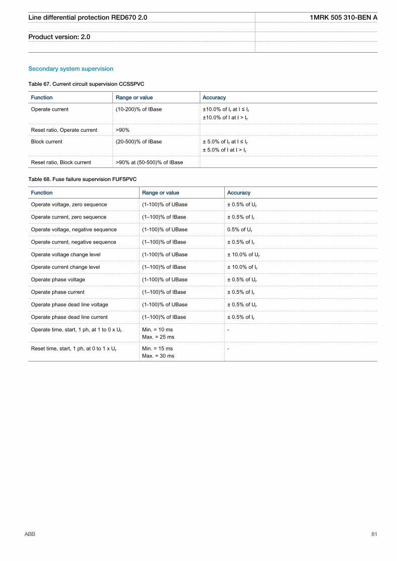
Secondary system supervision
Table 67. Current circuit supervision CCSSPVC
Function Range or value Accuracy
Operate current (10-200)% of IBase ±10.0% of Ir at I ≤ Ir±10.0% of I at I > Ir
Reset ratio, Operate current >90%
Block current (20-500)% of IBase ± 5.0% of Ir at I ≤ Ir± 5.0% of I at I > Ir
Reset ratio, Block current >90% at (50-500)% of IBase
Table 68. Fuse failure supervision FUFSPVC
Function Range or value Accuracy
Operate voltage, zero sequence (1-100)% of UBase ± 0.5% of Ur
Operate current, zero sequence (1–100)% of IBase ± 0.5% of Ir
Operate voltage, negative sequence (1-100)% of UBase 0.5% of Ur
Operate current, negative sequence (1–100)% of IBase ± 0.5% of Ir
Operate voltage change level (1-100)% of UBase ± 10.0% of Ur
Operate current change level (1–100)% of IBase ± 10.0% of Ir
Operate phase voltage (1-100)% of UBase ± 0.5% of Ur
Operate phase current (1–100)% of IBase ± 0.5% of Ir
Operate phase dead line voltage (1-100)% of UBase ± 0.5% of Ur
Operate phase dead line current (1–100)% of IBase ± 0.5% of Ir
Operate time, start, 1 ph, at 1 to 0 x Ur Min. = 10 msMax. = 25 ms
-
Reset time, start, 1 ph, at 0 to 1 x Ur Min. = 15 msMax. = 30 ms
-
Line differential protection RED670 2.0 1MRK 505 310-BEN A
Product version: 2.0
ABB 81
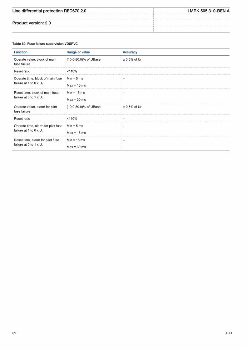
Table 69. Fuse failure supervision VDSPVC
Function Range or value Accuracy
Operate value, block of mainfuse failure
(10.0-80.0)% of UBase ± 0.5% of Ur
Reset ratio <110%
Operate time, block of main fusefailure at 1 to 0 x Ur
Min = 5 ms –
Max = 15 ms
Reset time, block of main fusefailure at 0 to 1 x Ur
Min = 15 ms –
Max = 30 ms
Operate value, alarm for pilotfuse failure
(10.0-80.0)% of UBase ± 0.5% of Ur
Reset ratio <110% –
Operate time, alarm for pilot fusefailure at 1 to 0 x Ur
Min = 5 ms –
Max = 15 ms
Reset time, alarm for pilot fusefailure at 0 to 1 x Ur
Min = 15 ms –
Max = 30 ms
Line differential protection RED670 2.0 1MRK 505 310-BEN A
Product version: 2.0
82 ABB
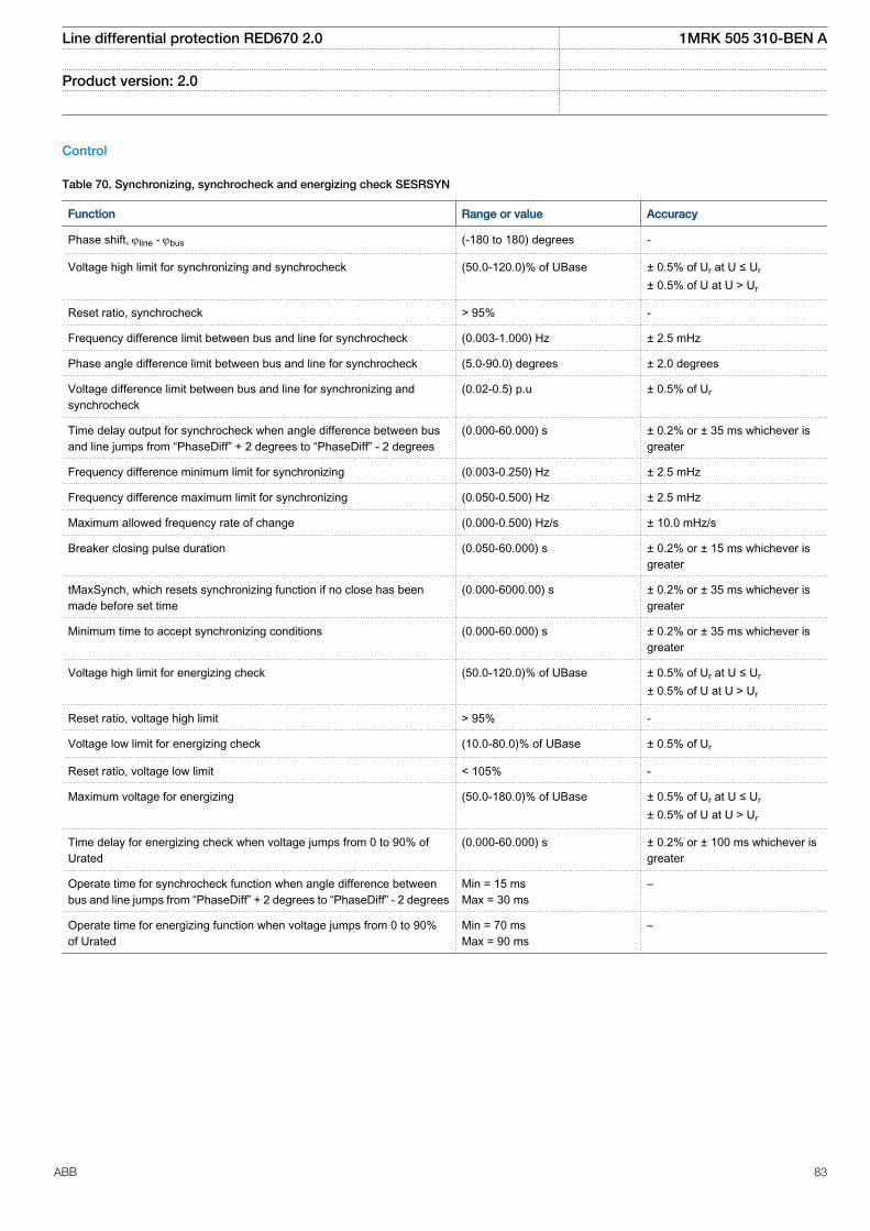
Control
Table 70. Synchronizing, synchrocheck and energizing check SESRSYN
Function Range or value Accuracy
Phase shift, jline - jbus (-180 to 180) degrees -
Voltage high limit for synchronizing and synchrocheck (50.0-120.0)% of UBase ± 0.5% of Ur at U ≤ Ur
± 0.5% of U at U > Ur
Reset ratio, synchrocheck > 95% -
Frequency difference limit between bus and line for synchrocheck (0.003-1.000) Hz ± 2.5 mHz
Phase angle difference limit between bus and line for synchrocheck (5.0-90.0) degrees ± 2.0 degrees
Voltage difference limit between bus and line for synchronizing andsynchrocheck
(0.02-0.5) p.u ± 0.5% of Ur
Time delay output for synchrocheck when angle difference between busand line jumps from “PhaseDiff” + 2 degrees to “PhaseDiff” - 2 degrees
(0.000-60.000) s ± 0.2% or ± 35 ms whichever isgreater
Frequency difference minimum limit for synchronizing (0.003-0.250) Hz ± 2.5 mHz
Frequency difference maximum limit for synchronizing (0.050-0.500) Hz ± 2.5 mHz
Maximum allowed frequency rate of change (0.000-0.500) Hz/s ± 10.0 mHz/s
Breaker closing pulse duration (0.050-60.000) s ± 0.2% or ± 15 ms whichever isgreater
tMaxSynch, which resets synchronizing function if no close has beenmade before set time
(0.000-6000.00) s ± 0.2% or ± 35 ms whichever isgreater
Minimum time to accept synchronizing conditions (0.000-60.000) s ± 0.2% or ± 35 ms whichever isgreater
Voltage high limit for energizing check (50.0-120.0)% of UBase ± 0.5% of Ur at U ≤ Ur
± 0.5% of U at U > Ur
Reset ratio, voltage high limit > 95% -
Voltage low limit for energizing check (10.0-80.0)% of UBase ± 0.5% of Ur
Reset ratio, voltage low limit < 105% -
Maximum voltage for energizing (50.0-180.0)% of UBase ± 0.5% of Ur at U ≤ Ur
± 0.5% of U at U > Ur
Time delay for energizing check when voltage jumps from 0 to 90% ofUrated
(0.000-60.000) s ± 0.2% or ± 100 ms whichever isgreater
Operate time for synchrocheck function when angle difference betweenbus and line jumps from “PhaseDiff” + 2 degrees to “PhaseDiff” - 2 degrees
Min = 15 msMax = 30 ms
–
Operate time for energizing function when voltage jumps from 0 to 90%of Urated
Min = 70 msMax = 90 ms
–
Line differential protection RED670 2.0 1MRK 505 310-BEN A
Product version: 2.0
ABB 83
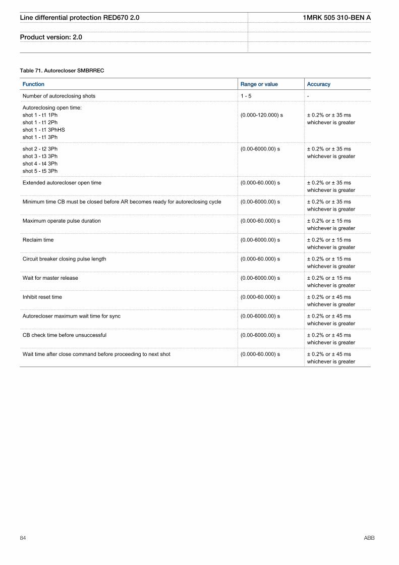
Table 71. Autorecloser SMBRREC
Function Range or value Accuracy
Number of autoreclosing shots 1 - 5 -
Autoreclosing open time:shot 1 - t1 1Phshot 1 - t1 2Phshot 1 - t1 3PhHSshot 1 - t1 3Ph
(0.000-120.000) s
± 0.2% or ± 35 mswhichever is greater
shot 2 - t2 3Phshot 3 - t3 3Phshot 4 - t4 3Phshot 5 - t5 3Ph
(0.00-6000.00) s ± 0.2% or ± 35 mswhichever is greater
Extended autorecloser open time (0.000-60.000) s ± 0.2% or ± 35 mswhichever is greater
Minimum time CB must be closed before AR becomes ready for autoreclosing cycle (0.00-6000.00) s ± 0.2% or ± 35 mswhichever is greater
Maximum operate pulse duration (0.000-60.000) s ± 0.2% or ± 15 mswhichever is greater
Reclaim time (0.00-6000.00) s ± 0.2% or ± 15 mswhichever is greater
Circuit breaker closing pulse length (0.000-60.000) s ± 0.2% or ± 15 mswhichever is greater
Wait for master release (0.00-6000.00) s ± 0.2% or ± 15 mswhichever is greater
Inhibit reset time (0.000-60.000) s ± 0.2% or ± 45 mswhichever is greater
Autorecloser maximum wait time for sync (0.00-6000.00) s ± 0.2% or ± 45 mswhichever is greater
CB check time before unsuccessful (0.00-6000.00) s ± 0.2% or ± 45 mswhichever is greater
Wait time after close command before proceeding to next shot (0.000-60.000) s ± 0.2% or ± 45 mswhichever is greater
Line differential protection RED670 2.0 1MRK 505 310-BEN A
Product version: 2.0
84 ABB
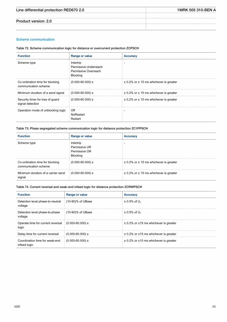
Scheme communication
Table 72. Scheme communication logic for distance or overcurrent protection ZCPSCH
Function Range or value Accuracy
Scheme type IntertripPermissive UnderreachPermissive OverreachBlocking
-
Co-ordination time for blockingcommunication scheme
(0.000-60.000) s ± 0.2% or ± 15 ms whichever is greater
Minimum duration of a send signal (0.000-60.000) s ± 0.2% or ± 15 ms whichever is greater
Security timer for loss of guardsignal detection
(0.000-60.000) s ± 0.2% or ± 15 ms whichever is greater
Operation mode of unblocking logic OffNoRestartRestart
-
Table 73. Phase segregated scheme communication logic for distance protection ZC1PPSCH
Function Range or value Accuracy
Scheme type IntertripPermissive URPermissive ORBlocking
-
Co-ordination time for blockingcommunication scheme
(0.000-60.000) s ± 0.2% or ± 15 ms whichever is greater
Minimum duration of a carrier sendsignal
(0.000-60.000) s ± 0.2% or ± 15 ms whichever is greater
Table 74. Current reversal and weak-end infeed logic for distance protection ZCRWPSCH
Function Range or value Accuracy
Detection level phase-to-neutralvoltage
(10-90)% of UBase ± 0.5% of Ur
Detection level phase-to-phasevoltage
(10-90)% of UBase ± 0.5% of Ur
Operate time for current reversallogic
(0.000-60.000) s ± 0.2% or ±15 ms whichever is greater
Delay time for current reversal (0.000-60.000) s ± 0.2% or ±15 ms whichever is greater
Coordination time for weak-endinfeed logic
(0.000-60.000) s ± 0.2% or ±15 ms whichever is greater
Line differential protection RED670 2.0 1MRK 505 310-BEN A
Product version: 2.0
ABB 85
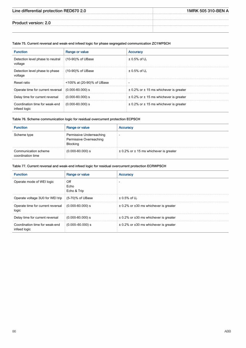
Table 75. Current reversal and weak-end infeed logic for phase segregated communication ZC1WPSCH
Function Range or value Accuracy
Detection level phase to neutralvoltage
(10-90)% of UBase ± 0.5% of Ur
Detection level phase to phasevoltage
(10-90)% of UBase ± 0.5% of Ur
Reset ratio <105% at (20-90)% of UBase -
Operate time for current reversal (0.000-60.000) s ± 0.2% or ± 15 ms whichever is greater
Delay time for current reversal (0.000-60.000) s ± 0.2% or ± 15 ms whichever is greater
Coordination time for weak-endinfeed logic
(0.000-60.000) s ± 0.2% or ± 15 ms whichever is greater
Table 76. Scheme communication logic for residual overcurrent protection ECPSCH
Function Range or value Accuracy
Scheme type Permissive UnderreachingPermissive OverreachingBlocking
-
Communication schemecoordination time
(0.000-60.000) s ± 0.2% or ± 15 ms whichever is greater
Table 77. Current reversal and weak-end infeed logic for residual overcurrent protection ECRWPSCH
Function Range or value Accuracy
Operate mode of WEI logic OffEchoEcho & Trip
-
Operate voltage 3U0 for WEI trip (5-70)% of UBase ± 0.5% of Ur
Operate time for current reversallogic
(0.000-60.000) s ± 0.2% or ±30 ms whichever is greater
Delay time for current reversal (0.000-60.000) s ± 0.2% or ±30 ms whichever is greater
Coordination time for weak-endinfeed logic
(0.000–60.000) s ± 0.2% or ±30 ms whichever is greater
Line differential protection RED670 2.0 1MRK 505 310-BEN A
Product version: 2.0
86 ABB
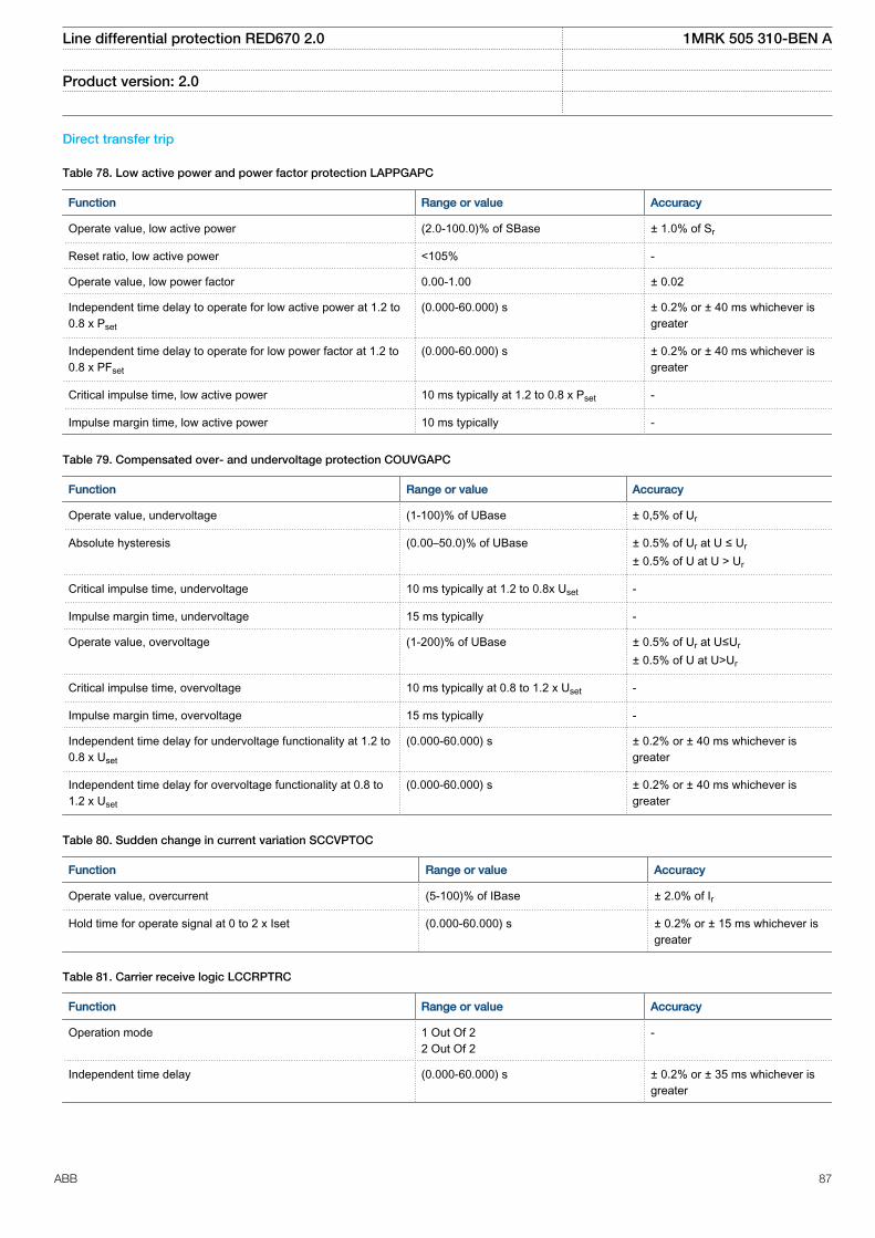
Direct transfer trip
Table 78. Low active power and power factor protection LAPPGAPC
Function Range or value Accuracy
Operate value, low active power (2.0-100.0)% of SBase ± 1.0% of Sr
Reset ratio, low active power <105% -
Operate value, low power factor 0.00-1.00 ± 0.02
Independent time delay to operate for low active power at 1.2 to0.8 x Pset
(0.000-60.000) s ± 0.2% or ± 40 ms whichever isgreater
Independent time delay to operate for low power factor at 1.2 to0.8 x PFset
(0.000-60.000) s ± 0.2% or ± 40 ms whichever isgreater
Critical impulse time, low active power 10 ms typically at 1.2 to 0.8 x Pset -
Impulse margin time, low active power 10 ms typically -
Table 79. Compensated over- and undervoltage protection COUVGAPC
Function Range or value Accuracy
Operate value, undervoltage (1-100)% of UBase ± 0,5% of Ur
Absolute hysteresis (0.00–50.0)% of UBase ± 0.5% of Ur at U ≤ Ur
± 0.5% of U at U > Ur
Critical impulse time, undervoltage 10 ms typically at 1.2 to 0.8x Uset -
Impulse margin time, undervoltage 15 ms typically -
Operate value, overvoltage (1-200)% of UBase ± 0.5% of Ur at U≤Ur
± 0.5% of U at U>Ur
Critical impulse time, overvoltage 10 ms typically at 0.8 to 1.2 x Uset -
Impulse margin time, overvoltage 15 ms typically -
Independent time delay for undervoltage functionality at 1.2 to0.8 x Uset
(0.000-60.000) s ± 0.2% or ± 40 ms whichever isgreater
Independent time delay for overvoltage functionality at 0.8 to1.2 x Uset
(0.000-60.000) s ± 0.2% or ± 40 ms whichever isgreater
Table 80. Sudden change in current variation SCCVPTOC
Function Range or value Accuracy
Operate value, overcurrent (5-100)% of IBase ± 2.0% of Ir
Hold time for operate signal at 0 to 2 x Iset (0.000-60.000) s ± 0.2% or ± 15 ms whichever isgreater
Table 81. Carrier receive logic LCCRPTRC
Function Range or value Accuracy
Operation mode 1 Out Of 22 Out Of 2
-
Independent time delay (0.000-60.000) s ± 0.2% or ± 35 ms whichever isgreater
Line differential protection RED670 2.0 1MRK 505 310-BEN A
Product version: 2.0
ABB 87
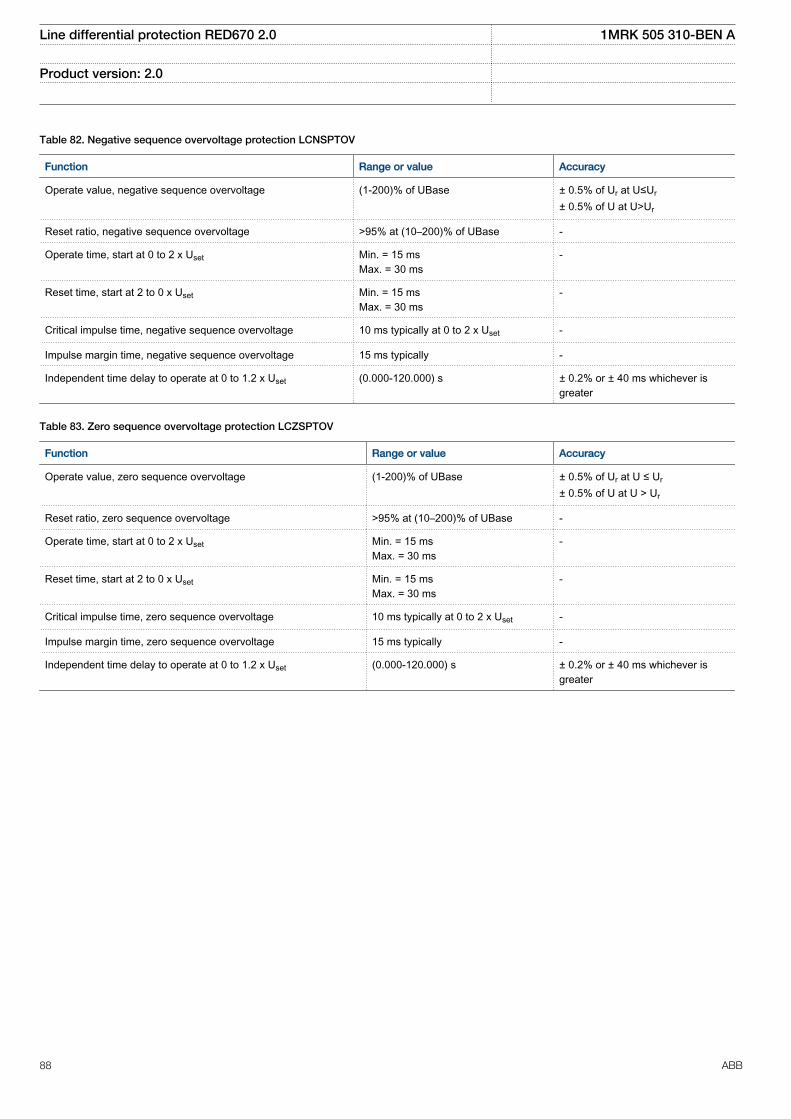
Table 82. Negative sequence overvoltage protection LCNSPTOV
Function Range or value Accuracy
Operate value, negative sequence overvoltage (1-200)% of UBase ± 0.5% of Ur at U≤Ur
± 0.5% of U at U>Ur
Reset ratio, negative sequence overvoltage >95% at (10–200)% of UBase -
Operate time, start at 0 to 2 x Uset Min. = 15 msMax. = 30 ms
-
Reset time, start at 2 to 0 x Uset Min. = 15 msMax. = 30 ms
-
Critical impulse time, negative sequence overvoltage 10 ms typically at 0 to 2 x Uset -
Impulse margin time, negative sequence overvoltage 15 ms typically -
Independent time delay to operate at 0 to 1.2 x Uset (0.000-120.000) s ± 0.2% or ± 40 ms whichever isgreater
Table 83. Zero sequence overvoltage protection LCZSPTOV
Function Range or value Accuracy
Operate value, zero sequence overvoltage (1-200)% of UBase ± 0.5% of Ur at U ≤ Ur
± 0.5% of U at U > Ur
Reset ratio, zero sequence overvoltage >95% at (10–200)% of UBase -
Operate time, start at 0 to 2 x Uset Min. = 15 msMax. = 30 ms
-
Reset time, start at 2 to 0 x Uset Min. = 15 msMax. = 30 ms
-
Critical impulse time, zero sequence overvoltage 10 ms typically at 0 to 2 x Uset -
Impulse margin time, zero sequence overvoltage 15 ms typically -
Independent time delay to operate at 0 to 1.2 x Uset (0.000-120.000) s ± 0.2% or ± 40 ms whichever isgreater
Line differential protection RED670 2.0 1MRK 505 310-BEN A
Product version: 2.0
88 ABB
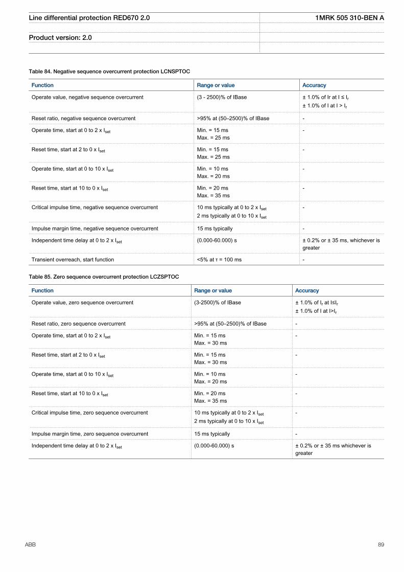
Table 84. Negative sequence overcurrent protection LCNSPTOC
Function Range or value Accuracy
Operate value, negative sequence overcurrent (3 - 2500)% of IBase ± 1.0% of Ir at I ≤ Ir± 1.0% of I at I > Ir
Reset ratio, negative sequence overcurrent >95% at (50–2500)% of IBase -
Operate time, start at 0 to 2 x Iset Min. = 15 msMax. = 25 ms
-
Reset time, start at 2 to 0 x Iset Min. = 15 msMax. = 25 ms
-
Operate time, start at 0 to 10 x Iset Min. = 10 msMax. = 20 ms
-
Reset time, start at 10 to 0 x Iset Min. = 20 msMax. = 35 ms
-
Critical impulse time, negative sequence overcurrent 10 ms typically at 0 to 2 x Iset
2 ms typically at 0 to 10 x Iset
-
Impulse margin time, negative sequence overcurrent 15 ms typically -
Independent time delay at 0 to 2 x Iset (0.000-60.000) s ± 0.2% or ± 35 ms, whichever isgreater
Transient overreach, start function <5% at τ = 100 ms -
Table 85. Zero sequence overcurrent protection LCZSPTOC
Function Range or value Accuracy
Operate value, zero sequence overcurrent (3-2500)% of IBase ± 1.0% of Ir at I≤Ir± 1.0% of I at I>Ir
Reset ratio, zero sequence overcurrent >95% at (50–2500)% of IBase -
Operate time, start at 0 to 2 x Iset Min. = 15 msMax. = 30 ms
-
Reset time, start at 2 to 0 x Iset Min. = 15 msMax. = 30 ms
-
Operate time, start at 0 to 10 x Iset Min. = 10 msMax. = 20 ms
-
Reset time, start at 10 to 0 x Iset Min. = 20 msMax. = 35 ms
-
Critical impulse time, zero sequence overcurrent 10 ms typically at 0 to 2 x Iset
2 ms typically at 0 to 10 x Iset
-
Impulse margin time, zero sequence overcurrent 15 ms typically -
Independent time delay at 0 to 2 x Iset (0.000-60.000) s ± 0.2% or ± 35 ms whichever isgreater
Line differential protection RED670 2.0 1MRK 505 310-BEN A
Product version: 2.0
ABB 89
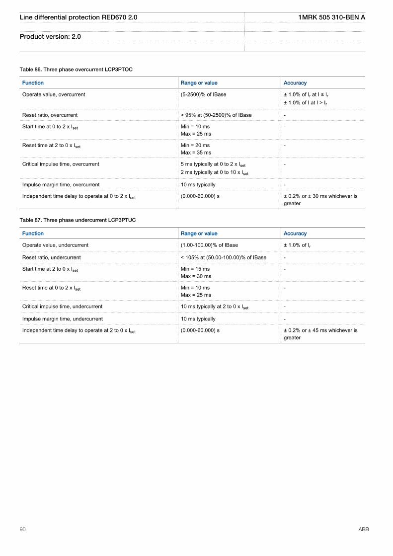
Table 86. Three phase overcurrent LCP3PTOC
Function Range or value Accuracy
Operate value, overcurrent (5-2500)% of IBase ± 1.0% of Ir at I ≤ Ir± 1.0% of I at I > Ir
Reset ratio, overcurrent > 95% at (50-2500)% of IBase -
Start time at 0 to 2 x Iset Min = 10 msMax = 25 ms
-
Reset time at 2 to 0 x Iset Min = 20 msMax = 35 ms
-
Critical impulse time, overcurrent 5 ms typically at 0 to 2 x Iset
2 ms typically at 0 to 10 x Iset
-
Impulse margin time, overcurrent 10 ms typically -
Independent time delay to operate at 0 to 2 x Iset (0.000-60.000) s ± 0.2% or ± 30 ms whichever isgreater
Table 87. Three phase undercurrent LCP3PTUC
Function Range or value Accuracy
Operate value, undercurrent (1.00-100.00)% of IBase ± 1.0% of Ir
Reset ratio, undercurrent < 105% at (50.00-100.00)% of IBase -
Start time at 2 to 0 x Iset Min = 15 msMax = 30 ms
-
Reset time at 0 to 2 x Iset Min = 10 msMax = 25 ms
-
Critical impulse time, undercurrent 10 ms typically at 2 to 0 x Iset -
Impulse margin time, undercurrent 10 ms typically -
Independent time delay to operate at 2 to 0 x Iset (0.000-60.000) s ± 0.2% or ± 45 ms whichever isgreater
Line differential protection RED670 2.0 1MRK 505 310-BEN A
Product version: 2.0
90 ABB
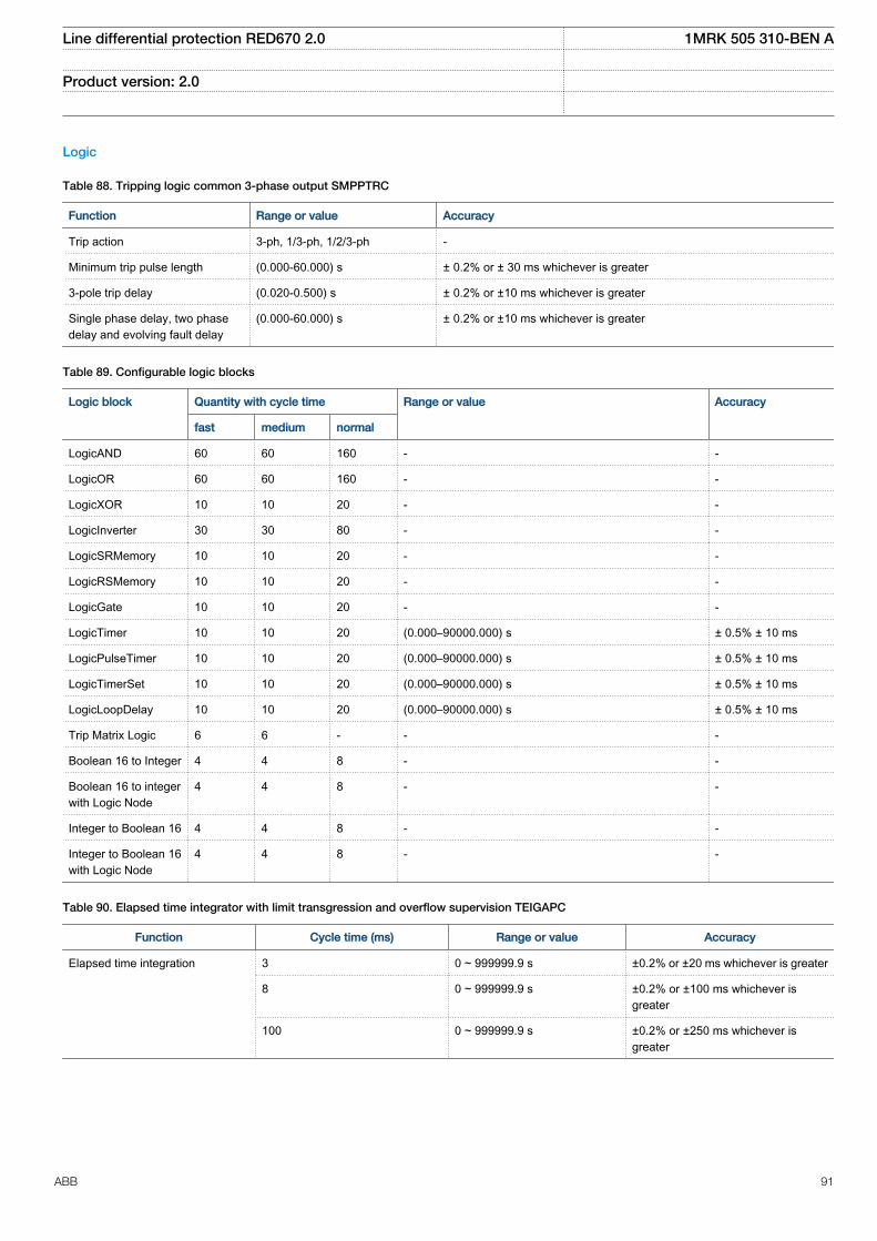
Logic
Table 88. Tripping logic common 3-phase output SMPPTRC
Function Range or value Accuracy
Trip action 3-ph, 1/3-ph, 1/2/3-ph -
Minimum trip pulse length (0.000-60.000) s ± 0.2% or ± 30 ms whichever is greater
3-pole trip delay (0.020-0.500) s ± 0.2% or ±10 ms whichever is greater
Single phase delay, two phasedelay and evolving fault delay
(0.000-60.000) s ± 0.2% or ±10 ms whichever is greater
Table 89. Configurable logic blocks
Logic block Quantity with cycle time Range or value Accuracy
fast medium normal
LogicAND 60 60 160 - -
LogicOR 60 60 160 - -
LogicXOR 10 10 20 - -
LogicInverter 30 30 80 - -
LogicSRMemory 10 10 20 - -
LogicRSMemory 10 10 20 - -
LogicGate 10 10 20 - -
LogicTimer 10 10 20 (0.000–90000.000) s ± 0.5% ± 10 ms
LogicPulseTimer 10 10 20 (0.000–90000.000) s ± 0.5% ± 10 ms
LogicTimerSet 10 10 20 (0.000–90000.000) s ± 0.5% ± 10 ms
LogicLoopDelay 10 10 20 (0.000–90000.000) s ± 0.5% ± 10 ms
Trip Matrix Logic 6 6 - - -
Boolean 16 to Integer 4 4 8 - -
Boolean 16 to integerwith Logic Node
4 4 8 - -
Integer to Boolean 16 4 4 8 - -
Integer to Boolean 16with Logic Node
4 4 8 - -
Table 90. Elapsed time integrator with limit transgression and overflow supervision TEIGAPC
Function Cycle time (ms) Range or value Accuracy
Elapsed time integration 3 0 ~ 999999.9 s ±0.2% or ±20 ms whichever is greater
8 0 ~ 999999.9 s ±0.2% or ±100 ms whichever isgreater
100 0 ~ 999999.9 s ±0.2% or ±250 ms whichever isgreater
Line differential protection RED670 2.0 1MRK 505 310-BEN A
Product version: 2.0
ABB 91
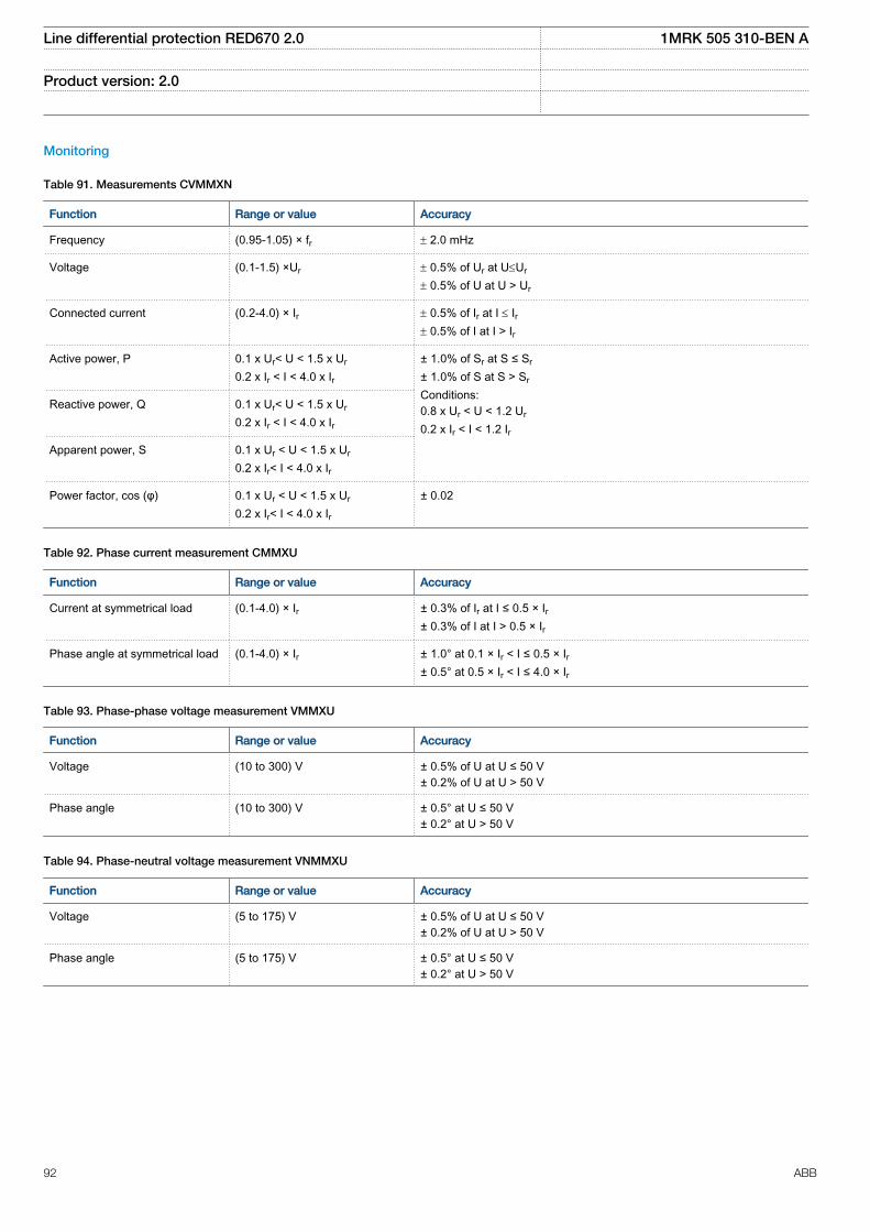
Monitoring
Table 91. Measurements CVMMXN
Function Range or value Accuracy
Frequency (0.95-1.05) × fr ± 2.0 mHz
Voltage (0.1-1.5) ×Ur ± 0.5% of Ur at U£Ur
± 0.5% of U at U > Ur
Connected current (0.2-4.0) × Ir ± 0.5% of Ir at I £ Ir± 0.5% of I at I > Ir
Active power, P 0.1 x Ur< U < 1.5 x Ur
0.2 x Ir < I < 4.0 x Ir± 1.0% of Sr at S ≤ Sr
± 1.0% of S at S > Sr
Conditions:0.8 x Ur < U < 1.2 Ur
0.2 x Ir < I < 1.2 Ir
Reactive power, Q 0.1 x Ur< U < 1.5 x Ur
0.2 x Ir < I < 4.0 x Ir
Apparent power, S 0.1 x Ur < U < 1.5 x Ur
0.2 x Ir< I < 4.0 x Ir
Power factor, cos (φ) 0.1 x Ur < U < 1.5 x Ur
0.2 x Ir< I < 4.0 x Ir± 0.02
Table 92. Phase current measurement CMMXU
Function Range or value Accuracy
Current at symmetrical load (0.1-4.0) × Ir ± 0.3% of Ir at I ≤ 0.5 × Ir± 0.3% of I at I > 0.5 × Ir
Phase angle at symmetrical load (0.1-4.0) × Ir ± 1.0° at 0.1 × Ir < I ≤ 0.5 × Ir± 0.5° at 0.5 × Ir < I ≤ 4.0 × Ir
Table 93. Phase-phase voltage measurement VMMXU
Function Range or value Accuracy
Voltage (10 to 300) V ± 0.5% of U at U ≤ 50 V± 0.2% of U at U > 50 V
Phase angle (10 to 300) V ± 0.5° at U ≤ 50 V± 0.2° at U > 50 V
Table 94. Phase-neutral voltage measurement VNMMXU
Function Range or value Accuracy
Voltage (5 to 175) V ± 0.5% of U at U ≤ 50 V± 0.2% of U at U > 50 V
Phase angle (5 to 175) V ± 0.5° at U ≤ 50 V± 0.2° at U > 50 V
Line differential protection RED670 2.0 1MRK 505 310-BEN A
Product version: 2.0
92 ABB
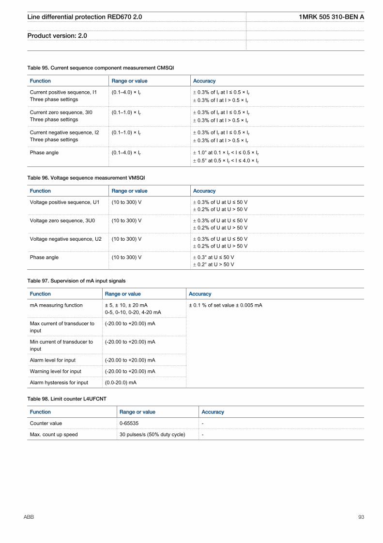
Table 95. Current sequence component measurement CMSQI
Function Range or value Accuracy
Current positive sequence, I1Three phase settings
(0.1–4.0) × Ir ± 0.3% of Ir at I ≤ 0.5 × Ir± 0.3% of I at I > 0.5 × Ir
Current zero sequence, 3I0Three phase settings
(0.1–1.0) × Ir ± 0.3% of Ir at I ≤ 0.5 × Ir± 0.3% of I at I > 0.5 × Ir
Current negative sequence, I2Three phase settings
(0.1–1.0) × Ir ± 0.3% of Ir at I ≤ 0.5 × Ir± 0.3% of I at I > 0.5 × Ir
Phase angle (0.1–4.0) × Ir ± 1.0° at 0.1 × Ir < I ≤ 0.5 × Ir± 0.5° at 0.5 × Ir < I ≤ 4.0 × Ir
Table 96. Voltage sequence measurement VMSQI
Function Range or value Accuracy
Voltage positive sequence, U1 (10 to 300) V ± 0.3% of U at U ≤ 50 V± 0.2% of U at U > 50 V
Voltage zero sequence, 3U0 (10 to 300) V ± 0.3% of U at U ≤ 50 V± 0.2% of U at U > 50 V
Voltage negative sequence, U2 (10 to 300) V ± 0.3% of U at U ≤ 50 V± 0.2% of U at U > 50 V
Phase angle (10 to 300) V ± 0.3° at U ≤ 50 V± 0.2° at U > 50 V
Table 97. Supervision of mA input signals
Function Range or value Accuracy
mA measuring function ± 5, ± 10, ± 20 mA0-5, 0-10, 0-20, 4-20 mA
± 0.1 % of set value ± 0.005 mA
Max current of transducer toinput
(-20.00 to +20.00) mA
Min current of transducer toinput
(-20.00 to +20.00) mA
Alarm level for input (-20.00 to +20.00) mA
Warning level for input (-20.00 to +20.00) mA
Alarm hysteresis for input (0.0-20.0) mA
Table 98. Limit counter L4UFCNT
Function Range or value Accuracy
Counter value 0-65535 -
Max. count up speed 30 pulses/s (50% duty cycle) -
Line differential protection RED670 2.0 1MRK 505 310-BEN A
Product version: 2.0
ABB 93
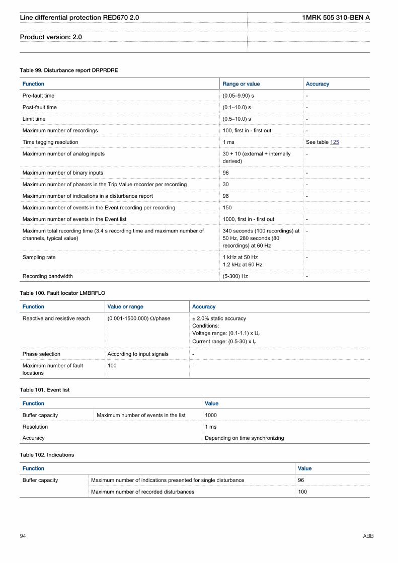
Table 99. Disturbance report DRPRDRE
Function Range or value Accuracy
Pre-fault time (0.05–9.90) s -
Post-fault time (0.1–10.0) s -
Limit time (0.5–10.0) s -
Maximum number of recordings 100, first in - first out -
Time tagging resolution 1 ms See table 125
Maximum number of analog inputs 30 + 10 (external + internallyderived)
-
Maximum number of binary inputs 96 -
Maximum number of phasors in the Trip Value recorder per recording 30 -
Maximum number of indications in a disturbance report 96 -
Maximum number of events in the Event recording per recording 150 -
Maximum number of events in the Event list 1000, first in - first out -
Maximum total recording time (3.4 s recording time and maximum number ofchannels, typical value)
340 seconds (100 recordings) at50 Hz, 280 seconds (80recordings) at 60 Hz
-
Sampling rate 1 kHz at 50 Hz1.2 kHz at 60 Hz
-
Recording bandwidth (5-300) Hz -
Table 100. Fault locator LMBRFLO
Function Value or range Accuracy
Reactive and resistive reach (0.001-1500.000) Ω/phase ± 2.0% static accuracyConditions:Voltage range: (0.1-1.1) x Ur
Current range: (0.5-30) x Ir
Phase selection According to input signals -
Maximum number of faultlocations
100 -
Table 101. Event list
Function Value
Buffer capacity Maximum number of events in the list 1000
Resolution 1 ms
Accuracy Depending on time synchronizing
Table 102. Indications
Function Value
Buffer capacity Maximum number of indications presented for single disturbance 96
Maximum number of recorded disturbances 100
Line differential protection RED670 2.0 1MRK 505 310-BEN A
Product version: 2.0
94 ABB
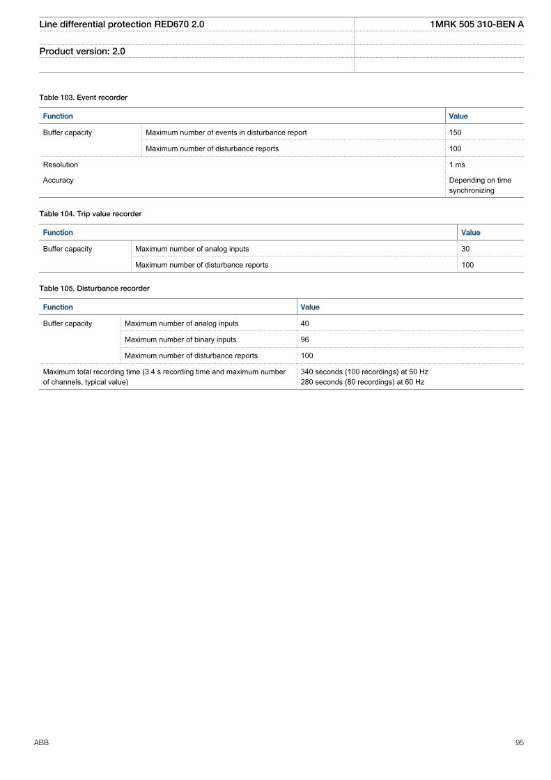
Table 103. Event recorder
Function Value
Buffer capacity Maximum number of events in disturbance report 150
Maximum number of disturbance reports 100
Resolution 1 ms
Accuracy Depending on timesynchronizing
Table 104. Trip value recorder
Function Value
Buffer capacity
Maximum number of analog inputs 30
Maximum number of disturbance reports 100
Table 105. Disturbance recorder
Function Value
Buffer capacity Maximum number of analog inputs 40
Maximum number of binary inputs 96
Maximum number of disturbance reports 100
Maximum total recording time (3.4 s recording time and maximum numberof channels, typical value)
340 seconds (100 recordings) at 50 Hz280 seconds (80 recordings) at 60 Hz
Line differential protection RED670 2.0 1MRK 505 310-BEN A
Product version: 2.0
ABB 95
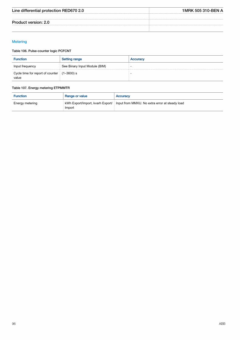
Metering
Table 106. Pulse-counter logic PCFCNT
Function Setting range Accuracy
Input frequency See Binary Input Module (BIM) -
Cycle time for report of countervalue
(1–3600) s -
Table 107. Energy metering ETPMMTR
Function Range or value Accuracy
Energy metering kWh Export/Import, kvarh Export/Import
Input from MMXU. No extra error at steady load
Line differential protection RED670 2.0 1MRK 505 310-BEN A
Product version: 2.0
96 ABB
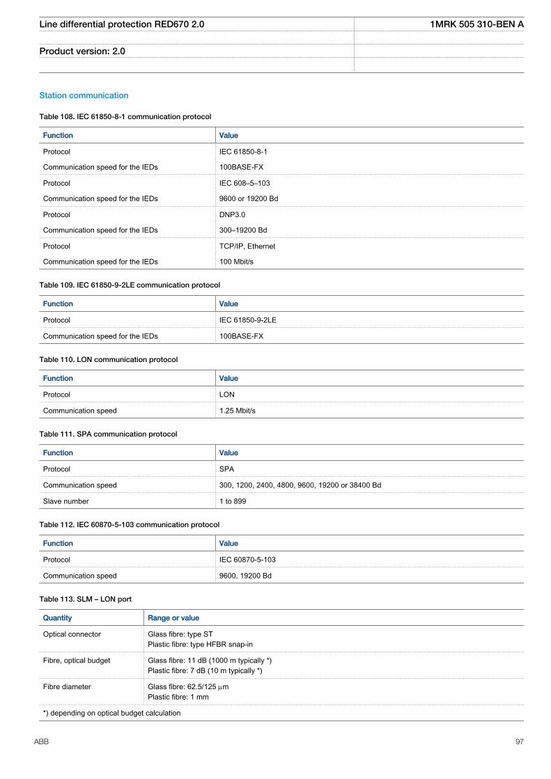
Station communication
Table 108. IEC 61850-8-1 communication protocol
Function Value
Protocol IEC 61850-8-1
Communication speed for the IEDs 100BASE-FX
Protocol IEC 608–5–103
Communication speed for the IEDs 9600 or 19200 Bd
Protocol DNP3.0
Communication speed for the IEDs 300–19200 Bd
Protocol TCP/IP, Ethernet
Communication speed for the IEDs 100 Mbit/s
Table 109. IEC 61850-9-2LE communication protocol
Function Value
Protocol IEC 61850-9-2LE
Communication speed for the IEDs 100BASE-FX
Table 110. LON communication protocol
Function Value
Protocol LON
Communication speed 1.25 Mbit/s
Table 111. SPA communication protocol
Function Value
Protocol SPA
Communication speed 300, 1200, 2400, 4800, 9600, 19200 or 38400 Bd
Slave number 1 to 899
Table 112. IEC 60870-5-103 communication protocol
Function Value
Protocol IEC 60870-5-103
Communication speed 9600, 19200 Bd
Table 113. SLM – LON port
Quantity Range or value
Optical connector Glass fibre: type STPlastic fibre: type HFBR snap-in
Fibre, optical budget Glass fibre: 11 dB (1000 m typically *)Plastic fibre: 7 dB (10 m typically *)
Fibre diameter Glass fibre: 62.5/125 mmPlastic fibre: 1 mm
*) depending on optical budget calculation
Line differential protection RED670 2.0 1MRK 505 310-BEN A
Product version: 2.0
ABB 97
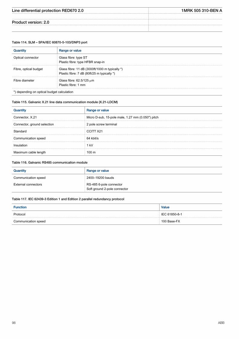
Table 114. SLM – SPA/IEC 60870-5-103/DNP3 port
Quantity Range or value
Optical connector Glass fibre: type STPlastic fibre: type HFBR snap-in
Fibre, optical budget Glass fibre: 11 dB (3000ft/1000 m typically *)Plastic fibre: 7 dB (80ft/25 m typically *)
Fibre diameter Glass fibre: 62.5/125 mmPlastic fibre: 1 mm
*) depending on optical budget calculation
Table 115. Galvanic X.21 line data communication module (X.21-LDCM)
Quantity Range or value
Connector, X.21 Micro D-sub, 15-pole male, 1.27 mm (0.050") pitch
Connector, ground selection 2 pole screw terminal
Standard CCITT X21
Communication speed 64 kbit/s
Insulation 1 kV
Maximum cable length 100 m
Table 116. Galvanic RS485 communication module
Quantity Range or value
Communication speed 2400–19200 bauds
External connectors RS-485 6-pole connectorSoft ground 2-pole connector
Table 117. IEC 62439-3 Edition 1 and Edition 2 parallel redundancy protocol
Function Value
Protocol IEC 61850-8-1
Communication speed 100 Base-FX
Line differential protection RED670 2.0 1MRK 505 310-BEN A
Product version: 2.0
98 ABB
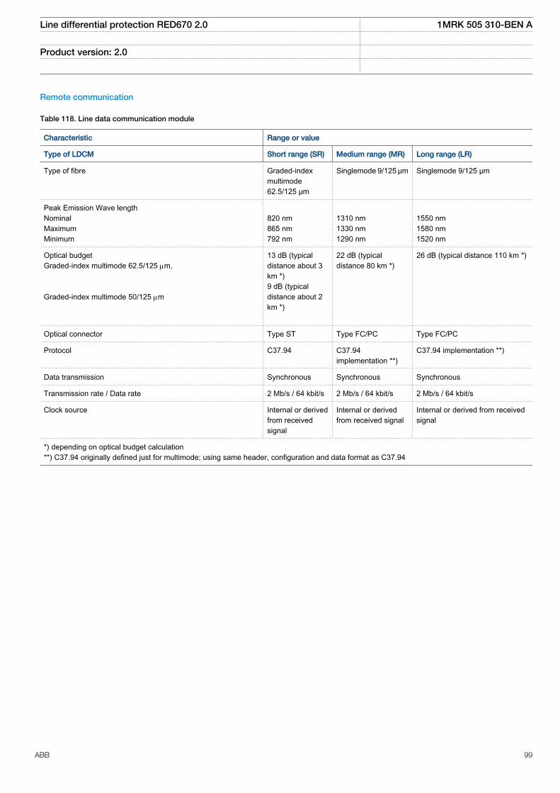
Remote communication
Table 118. Line data communication module
Characteristic Range or value
Type of LDCM Short range (SR) Medium range (MR) Long range (LR)
Type of fibre Graded-indexmultimode62.5/125 µm
Singlemode 9/125 µm Singlemode 9/125 µm
Peak Emission Wave lengthNominalMaximumMinimum
820 nm865 nm792 nm
1310 nm1330 nm1290 nm
1550 nm1580 nm1520 nm
Optical budgetGraded-index multimode 62.5/125 mm, Graded-index multimode 50/125 mm
13 dB (typicaldistance about 3km *)9 dB (typicaldistance about 2km *)
22 dB (typicaldistance 80 km *)
26 dB (typical distance 110 km *)
Optical connector Type ST Type FC/PC Type FC/PC
Protocol C37.94 C37.94implementation **)
C37.94 implementation **)
Data transmission Synchronous Synchronous Synchronous
Transmission rate / Data rate 2 Mb/s / 64 kbit/s 2 Mb/s / 64 kbit/s 2 Mb/s / 64 kbit/s
Clock source Internal or derivedfrom receivedsignal
Internal or derivedfrom received signal
Internal or derived from receivedsignal
*) depending on optical budget calculation**) C37.94 originally defined just for multimode; using same header, configuration and data format as C37.94
Line differential protection RED670 2.0 1MRK 505 310-BEN A
Product version: 2.0
ABB 99
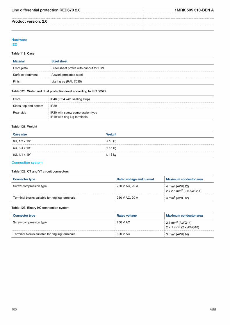
HardwareIED
Table 119. Case
Material Steel sheet
Front plate Steel sheet profile with cut-out for HMI
Surface treatment Aluzink preplated steel
Finish Light grey (RAL 7035)
Table 120. Water and dust protection level according to IEC 60529
Front IP40 (IP54 with sealing strip)
Sides, top and bottom IP20
Rear side IP20 with screw compression typeIP10 with ring lug terminals
Table 121. Weight
Case size Weight
6U, 1/2 x 19” £ 10 kg
6U, 3/4 x 19” £ 15 kg
6U, 1/1 x 19” £ 18 kg
Connection system
Table 122. CT and VT circuit connectors
Connector type Rated voltage and current Maximum conductor area
Screw compression type 250 V AC, 20 A 4 mm2 (AWG12)2 x 2.5 mm2 (2 x AWG14)
Terminal blocks suitable for ring lug terminals 250 V AC, 20 A 4 mm2 (AWG12)
Table 123. Binary I/O connection system
Connector type Rated voltage Maximum conductor area
Screw compression type 250 V AC 2.5 mm2 (AWG14)2 × 1 mm2 (2 x AWG18)
Terminal blocks suitable for ring lug terminals 300 V AC 3 mm2 (AWG14)
Line differential protection RED670 2.0 1MRK 505 310-BEN A
Product version: 2.0
100 ABB
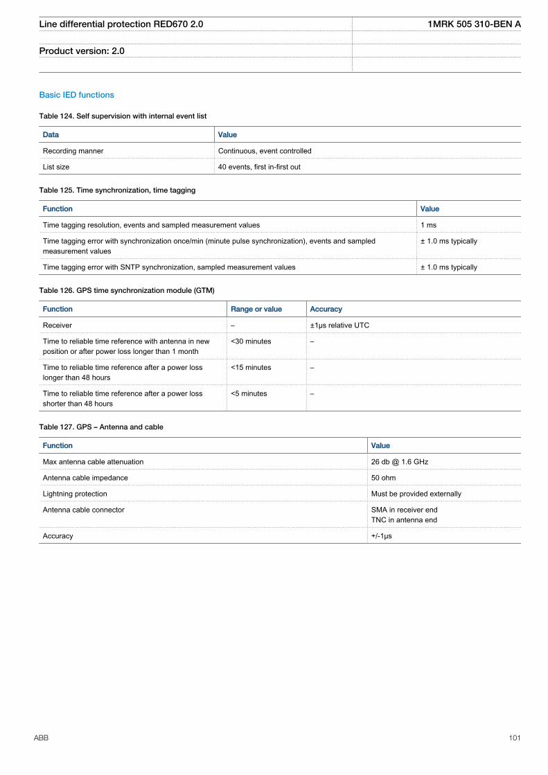
Basic IED functions
Table 124. Self supervision with internal event list
Data Value
Recording manner Continuous, event controlled
List size 40 events, first in-first out
Table 125. Time synchronization, time tagging
Function Value
Time tagging resolution, events and sampled measurement values 1 ms
Time tagging error with synchronization once/min (minute pulse synchronization), events and sampledmeasurement values
± 1.0 ms typically
Time tagging error with SNTP synchronization, sampled measurement values ± 1.0 ms typically
Table 126. GPS time synchronization module (GTM)
Function Range or value Accuracy
Receiver – ±1µs relative UTC
Time to reliable time reference with antenna in newposition or after power loss longer than 1 month
<30 minutes –
Time to reliable time reference after a power losslonger than 48 hours
<15 minutes –
Time to reliable time reference after a power lossshorter than 48 hours
<5 minutes –
Table 127. GPS – Antenna and cable
Function Value
Max antenna cable attenuation 26 db @ 1.6 GHz
Antenna cable impedance 50 ohm
Lightning protection Must be provided externally
Antenna cable connector SMA in receiver endTNC in antenna end
Accuracy +/-1μs
Line differential protection RED670 2.0 1MRK 505 310-BEN A
Product version: 2.0
ABB 101
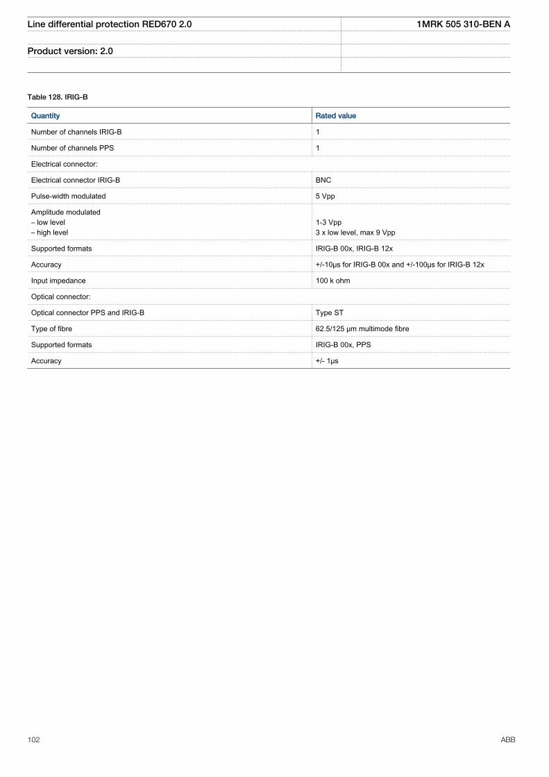
Table 128. IRIG-B
Quantity Rated value
Number of channels IRIG-B 1
Number of channels PPS 1
Electrical connector:
Electrical connector IRIG-B BNC
Pulse-width modulated 5 Vpp
Amplitude modulated– low level– high level
1-3 Vpp3 x low level, max 9 Vpp
Supported formats IRIG-B 00x, IRIG-B 12x
Accuracy +/-10μs for IRIG-B 00x and +/-100μs for IRIG-B 12x
Input impedance 100 k ohm
Optical connector:
Optical connector PPS and IRIG-B Type ST
Type of fibre 62.5/125 μm multimode fibre
Supported formats IRIG-B 00x, PPS
Accuracy +/- 1μs
Line differential protection RED670 2.0 1MRK 505 310-BEN A
Product version: 2.0
102 ABB
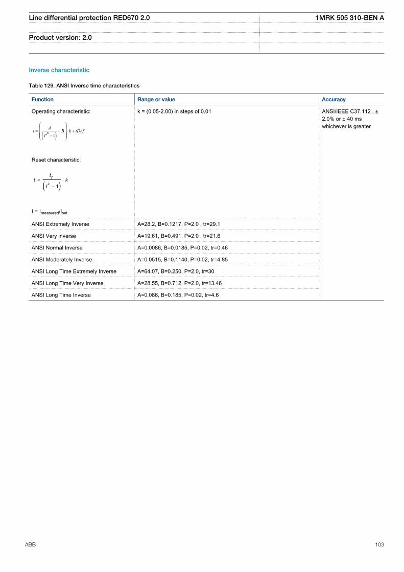
Inverse characteristic
Table 129. ANSI Inverse time characteristics
Function Range or value Accuracy
Operating characteristic:
( )1PAt B k tDef
I
æ öç ÷= + × +ç ÷ç - ÷è ø
EQUATION1249-SMALL V2 EN
Reset characteristic:
( )2 1= ×
-
trt kI
EQUATION1250-SMALL V1 EN
I = Imeasured/Iset
k = (0.05-2.00) in steps of 0.01 ANSI/IEEE C37.112 , ±2.0% or ± 40 mswhichever is greater
ANSI Extremely Inverse A=28.2, B=0.1217, P=2.0 , tr=29.1
ANSI Very inverse A=19.61, B=0.491, P=2.0 , tr=21.6
ANSI Normal Inverse A=0.0086, B=0.0185, P=0.02, tr=0.46
ANSI Moderately Inverse A=0.0515, B=0.1140, P=0.02, tr=4.85
ANSI Long Time Extremely Inverse A=64.07, B=0.250, P=2.0, tr=30
ANSI Long Time Very Inverse A=28.55, B=0.712, P=2.0, tr=13.46
ANSI Long Time Inverse A=0.086, B=0.185, P=0.02, tr=4.6
Line differential protection RED670 2.0 1MRK 505 310-BEN A
Product version: 2.0
ABB 103
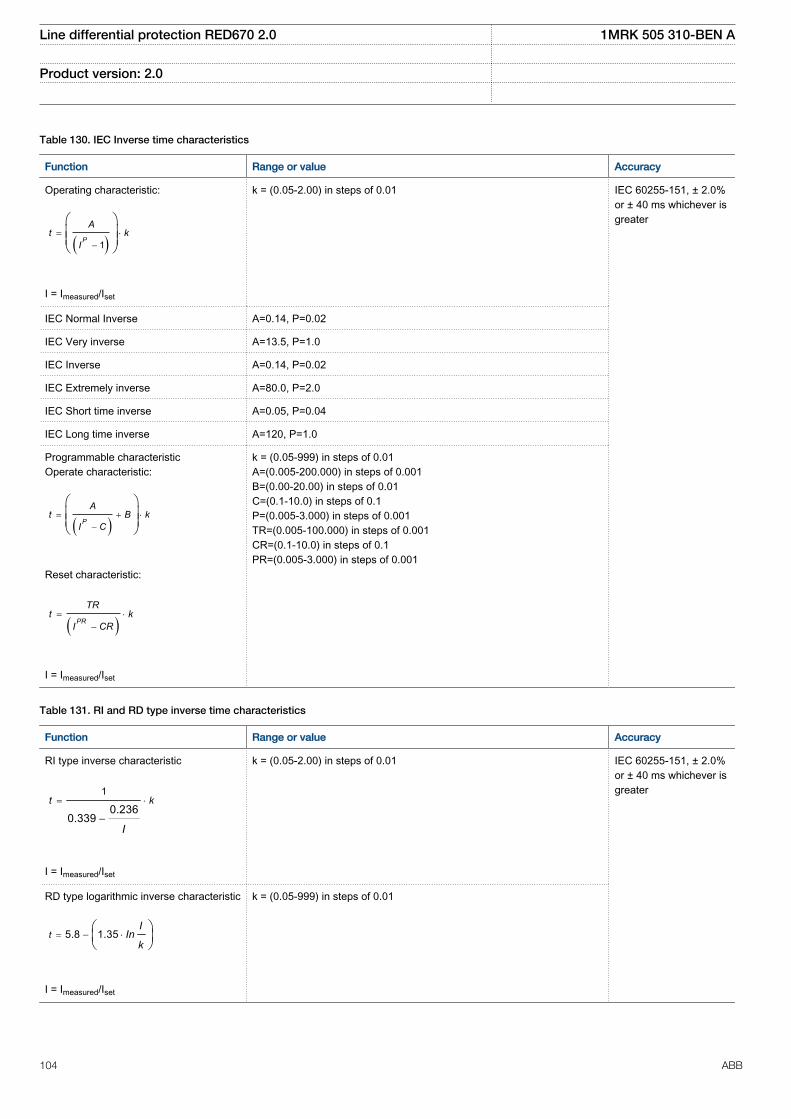
Table 130. IEC Inverse time characteristics
Function Range or value Accuracy
Operating characteristic:
( )1= ×
-
æ öç ÷ç ÷è ø
P
At k
I
EQUATION1251-SMALL V1 EN
I = Imeasured/Iset
k = (0.05-2.00) in steps of 0.01 IEC 60255-151, ± 2.0%or ± 40 ms whichever isgreater
IEC Normal Inverse A=0.14, P=0.02
IEC Very inverse A=13.5, P=1.0
IEC Inverse A=0.14, P=0.02
IEC Extremely inverse A=80.0, P=2.0
IEC Short time inverse A=0.05, P=0.04
IEC Long time inverse A=120, P=1.0
Programmable characteristicOperate characteristic:
( )= + ×
-
æ öç ÷ç ÷è ø
P
At B k
I C
EQUATION1370-SMALL V1 EN
Reset characteristic:
( )= ×
-PR
TRt k
I CR
EQUATION1253-SMALL V1 EN
I = Imeasured/Iset
k = (0.05-999) in steps of 0.01A=(0.005-200.000) in steps of 0.001B=(0.00-20.00) in steps of 0.01C=(0.1-10.0) in steps of 0.1P=(0.005-3.000) in steps of 0.001TR=(0.005-100.000) in steps of 0.001CR=(0.1-10.0) in steps of 0.1PR=(0.005-3.000) in steps of 0.001
Table 131. RI and RD type inverse time characteristics
Function Range or value Accuracy
RI type inverse characteristic
1
0.2360.339
= ×
-
t k
IEQUATION1137-SMALL V1 EN
I = Imeasured/Iset
k = (0.05-2.00) in steps of 0.01 IEC 60255-151, ± 2.0%or ± 40 ms whichever isgreater
RD type logarithmic inverse characteristic
5.8 1.35= - ×æ öç ÷è ø
tI
Ink
EQUATION1138-SMALL V1 EN
I = Imeasured/Iset
k = (0.05-999) in steps of 0.01
Line differential protection RED670 2.0 1MRK 505 310-BEN A
Product version: 2.0
104 ABB
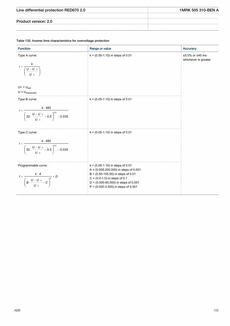
Table 132. Inverse time characteristics for overvoltage protection
Function Range or value Accuracy
Type A curve:
=- >
>
æ öç ÷è ø
tk
U U
U
EQUATION1436-SMALL V1 EN
U> = Uset
U = Umeasured
k = (0.05-1.10) in steps of 0.01 ±5.0% or ±45 mswhichever is greater
Type B curve:
2.0
480
32 0.5 0.035
=×
- >× - -
>
æ öç ÷è ø
tk
U U
U
EQUATION1437-SMALL V1 EN
k = (0.05-1.10) in steps of 0.01
Type C curve:
3.0
480
32 0.5 0.035
=×
- >× - -
>
æ öç ÷è ø
tk
U U
U
EQUATION1438-SMALL V1 EN
k = (0.05-1.10) in steps of 0.01
Programmable curve:
×= +
- >× -
>
æ öç ÷è ø
P
k At D
U UB C
U
EQUATION1439-SMALL V1 EN
k = (0.05-1.10) in steps of 0.01A = (0.005-200.000) in steps of 0.001B = (0.50-100.00) in steps of 0.01C = (0.0-1.0) in steps of 0.1D = (0.000-60.000) in steps of 0.001P = (0.000-3.000) in steps of 0.001
Line differential protection RED670 2.0 1MRK 505 310-BEN A
Product version: 2.0
ABB 105
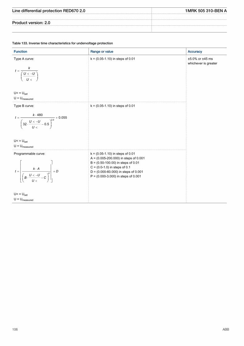
Table 133. Inverse time characteristics for undervoltage protection
Function Range or value Accuracy
Type A curve:
=< -
<
æ öç ÷è ø
kt
U U
UEQUATION1431-SMALL V1 EN
U< = Uset
U = Umeasured
k = (0.05-1.10) in steps of 0.01 ±5.0% or ±45 mswhichever is greater
Type B curve:
2.0
4800.055
32 0.5
×= +
< -× -
<
æ öç ÷è ø
kt
U U
U
EQUATION1432-SMALL V1 EN
U< = Uset
U = Umeasured
k = (0.05-1.10) in steps of 0.01
Programmable curve:
×= +
< -× -
<
é ùê úê úê úæ öê úç ÷ë è ø û
P
k At D
U UB C
U
EQUATION1433-SMALL V1 EN
U< = Uset
U = Umeasured
k = (0.05-1.10) in steps of 0.01A = (0.005-200.000) in steps of 0.001B = (0.50-100.00) in steps of 0.01C = (0.0-1.0) in steps of 0.1D = (0.000-60.000) in steps of 0.001P = (0.000-3.000) in steps of 0.001
Line differential protection RED670 2.0 1MRK 505 310-BEN A
Product version: 2.0
106 ABB
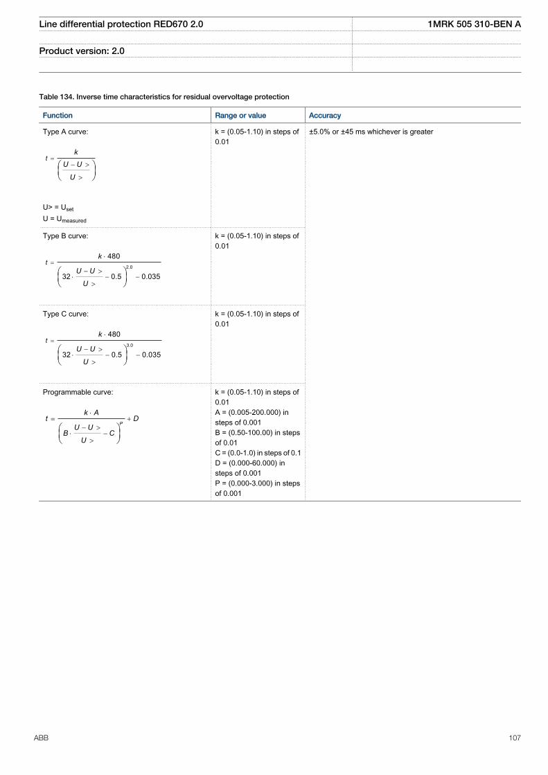
Table 134. Inverse time characteristics for residual overvoltage protection
Function Range or value Accuracy
Type A curve:
=- >
>
æ öç ÷è ø
tk
U U
U
EQUATION1436-SMALL V1 EN
U> = Uset
U = Umeasured
k = (0.05-1.10) in steps of0.01
±5.0% or ±45 ms whichever is greater
Type B curve:
2.0
480
32 0.5 0.035
=×
- >× - -
>
æ öç ÷è ø
tk
U U
U
EQUATION1437-SMALL V1 EN
k = (0.05-1.10) in steps of0.01
Type C curve:
3.0
480
32 0.5 0.035
=×
- >× - -
>
æ öç ÷è ø
tk
U U
U
EQUATION1438-SMALL V1 EN
k = (0.05-1.10) in steps of0.01
Programmable curve:
×= +
- >× -
>
æ öç ÷è ø
P
k At D
U UB C
U
EQUATION1439-SMALL V1 EN
k = (0.05-1.10) in steps of0.01A = (0.005-200.000) insteps of 0.001B = (0.50-100.00) in stepsof 0.01C = (0.0-1.0) in steps of 0.1D = (0.000-60.000) insteps of 0.001P = (0.000-3.000) in stepsof 0.001
Line differential protection RED670 2.0 1MRK 505 310-BEN A
Product version: 2.0
ABB 107
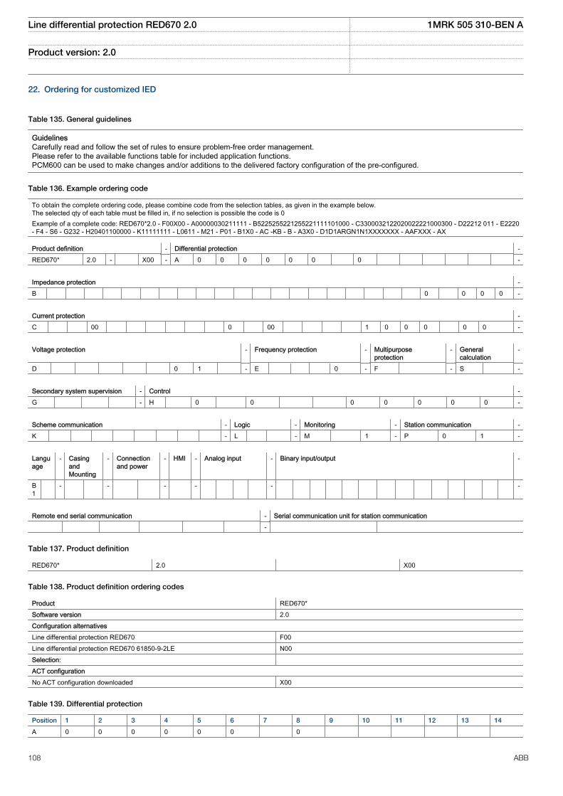
22. Ordering for customized IED
Table 135. General guidelines
GuidelinesCarefully read and follow the set of rules to ensure problem-free order management.Please refer to the available functions table for included application functions.PCM600 can be used to make changes and/or additions to the delivered factory configuration of the pre-configured.
Table 136. Example ordering code
To obtain the complete ordering code, please combine code from the selection tables, as given in the example below.The selected qty of each table must be filled in, if no selection is possible the code is 0Example of a complete code: RED670*2.0 - F00X00 - A00000030211111 - B5225255221255221111101000 - C3300032122020022221000300 - D22212 011 - E2220- F4 - S6 - G232 - H20401100000 - K11111111 - L0611 - M21 - P01 - B1X0 - AC -KB - B - A3X0 - D1D1ARGN1N1XXXXXXX - AAFXXX - AX
Product definition - Differential protection -RED670* 2.0 - X00 - A 0 0 0 0 0 0 0 -
Impedance protection -B 0 0 0 0 -
Current protection -C 00 0 00 1 0 0 0 0 0 -
Voltage protection - Frequency protection - Multipurposeprotection
- Generalcalculation
-
D 0 1 - E 0 - F - S -
Secondary system supervision - Control -G - H 0 0 0 0 0 0 0 -
Scheme communication - Logic - Monitoring - Station communication -K - L - M 1 - P 0 1 -
Language
- CasingandMounting
- Connectionand power
- HMI - Analog input - Binary input/output -
B1
- - - - - -
Remote end serial communication - Serial communication unit for station communication -
Table 137. Product definition
RED670* 2.0 X00
Table 138. Product definition ordering codes
Product RED670*Software version 2.0Configuration alternativesLine differential protection RED670 F00Line differential protection RED670 61850-9-2LE N00Selection: ACT configurationNo ACT configuration downloaded X00
Table 139. Differential protection
Position 1 2 3 4 5 6 7 8 9 10 11 12 13 14
A 0 0 0 0 0 0 0
Line differential protection RED670 2.0 1MRK 505 310-BEN A
Product version: 2.0
108 ABB
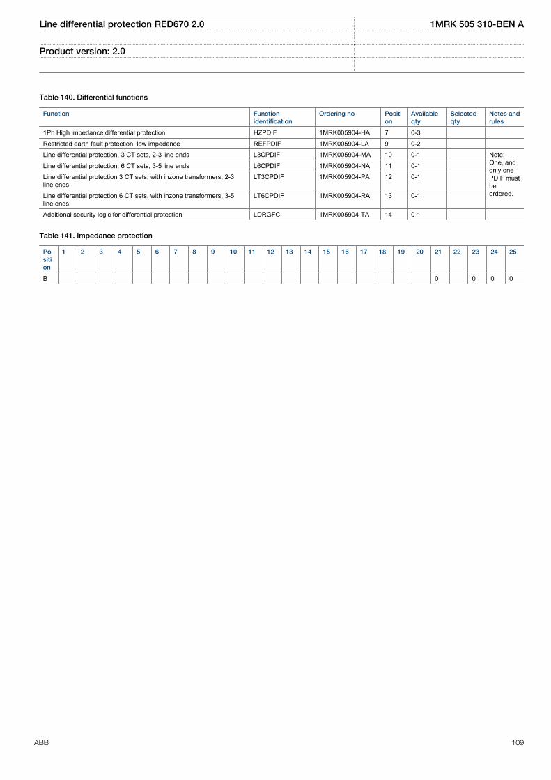
Table 140. Differential functions
Function Functionidentification
Ordering no Position
Availableqty
Selectedqty
Notes andrules
1Ph High impedance differential protection HZPDIF 1MRK005904-HA 7 0-3 Restricted earth fault protection, low impedance REFPDIF 1MRK005904-LA 9 0-2 Line differential protection, 3 CT sets, 2-3 line ends L3CPDIF 1MRK005904-MA 10 0-1 Note:
One, andonly onePDIF mustbeordered.
Line differential protection, 6 CT sets, 3-5 line ends L6CPDIF 1MRK005904-NA 11 0-1 Line differential protection 3 CT sets, with inzone transformers, 2-3line ends
LT3CPDIF 1MRK005904-PA 12 0-1
Line differential protection 6 CT sets, with inzone transformers, 3-5line ends
LT6CPDIF 1MRK005904-RA 13 0-1
Additional security logic for differential protection LDRGFC 1MRK005904-TA 14 0-1
Table 141. Impedance protection
Position
1 2 3 4 5 6 7 8 9 10 11 12 13 14 15 16 17 18 19 20 21 22 23 24 25
B 0 0 0 0
Line differential protection RED670 2.0 1MRK 505 310-BEN A
Product version: 2.0
ABB 109
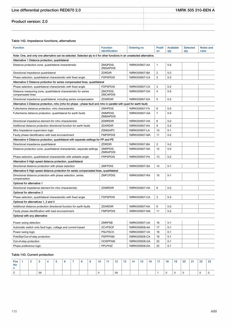
Table 142. Impedance functions, alternatives
Function Functionidentification
Ordering no Position
Availableqty
Selectedqty
Notes andrules
Note: One, and only one alternative can be selected. Selected qty is 0 for other functions in an unselected alternative.Alternative 1 Distance protection, quadrilateralDistance protection zone, quadrilateral characteristic ZMQPDIS,
ZMQAPDIS1MRK005907-AA 1 0-5
Directional impedance quadrilateral ZDRDIR 1MRK005907-BA 2 0-2 Phase selection, quadrilateral characteristic with fixed angle FDPSPDIS 1MRK005907-CA 3 0-2 Alternative 2 Distance protection for series compensated lines, quadrilateralPhase selection, quadrilateral characteristic with fixed angle FDPSPDIS 1MRK005907-CA 3 0-2 Distance measuring zone, quadrilateral characteristic for seriescompensated lines
ZMCPDIS,ZMCAPDIS
1MRK005907-DA 4 0-5
Directional impedance quadrilateral, including series compensation ZDSRDIR 1MRK005907-EA 5 0-2 Alternative 3 Distance protection, mho (mho for phase - phase fault and mho in parallel with quad for earth fault)Fullscheme distance protection, mho characteristic ZMHPDIS 1MRK005907-FA 6 0-5 Fullscheme distance protection, quadrilateral for earth faults ZMMPDIS,
ZMMAPDIS1MRK005907-GA 7 0-5
Directional impedance element for mho characteristic ZDMRDIR 1MRK005907-HA 8 0-2 Additional distance protection directional function for earth faults ZDARDIR 1MRK005907-KA 9 0-2 Mho Impedance supervision logic ZSMGAPC 1MRK005907-LA 10 0-1 Faulty phase identification with load encroachment FMPSPDIS 1MRK005907-MA 11 0-2 Alternative 4 Distance protection, quadrilateral with separate settings for PP and PEDirectional impedance quadrilateral ZDRDIR 1MRK005907-BA 2 0-2 Distance protection zone, quadrilateral characteristic, separate settings ZMRPDIS,
ZMRAPDIS1MRK005907-NA 12 0-5
Phase selection, quadrilateral characteristic with settable angle FRPSPDIS 1MRK005907-PA 13 0-2 Alternative 5 High speed distance protection, quadrilateral Directional distance protection with phase selection ZMFPDIS 1MRK005907-SA 14 0-1 Alternative 6 High speed distance protection for series compensated lines, quadrilateralDirectional distance protection with phase selection, seriescompensation
ZMFCPDIS 1MRK005907-RA 15 0-1
Optional for alternative 1Directional impedance element for mho characteristic ZDMRDIR 1MRK005907-HA 8 0-2 Optional for alternative 3Phase selection, quadrilateral characteristic with fixed angle FDPSPDIS 1MRK005907-CA 3 0-2 Optional for alternatives 1, 2 and 4Additional distance protection directional function for earth faults ZDARDIR 1MRK005907-KA 9 0-2 Faulty phase identification with load encroachment FMPSPDIS 1MRK005907-MA 11 0-2 Optional with any alternative
Power swing detection ZMRPSB 1MRK005907-UA 16 0-1 Automatic switch onto fault logic, voltage and current based ZCVPSOF 1MRK005908-AA 17 0-1 Power swing logic PSLPSCH 1MRK005907-VA 18 0-1 PoleSlip/Out-of-step protection PSPPPAM 1MRK005908-CA 19 0-1 Out-of-step protection OOSPPAM 1MRK005908-GA 20 0-1 Phase preference logic PPLPHIZ 1MRK005908-DA 22 0-1
Table 143. Current protection
Position
1 2 3 4 5 6 7 8 9 10 11 12 13 14 15 16 17 18 19 20 21 22 23
C 00 0 00 1 0 0 0 0 0
Line differential protection RED670 2.0 1MRK 505 310-BEN A
Product version: 2.0
110 ABB
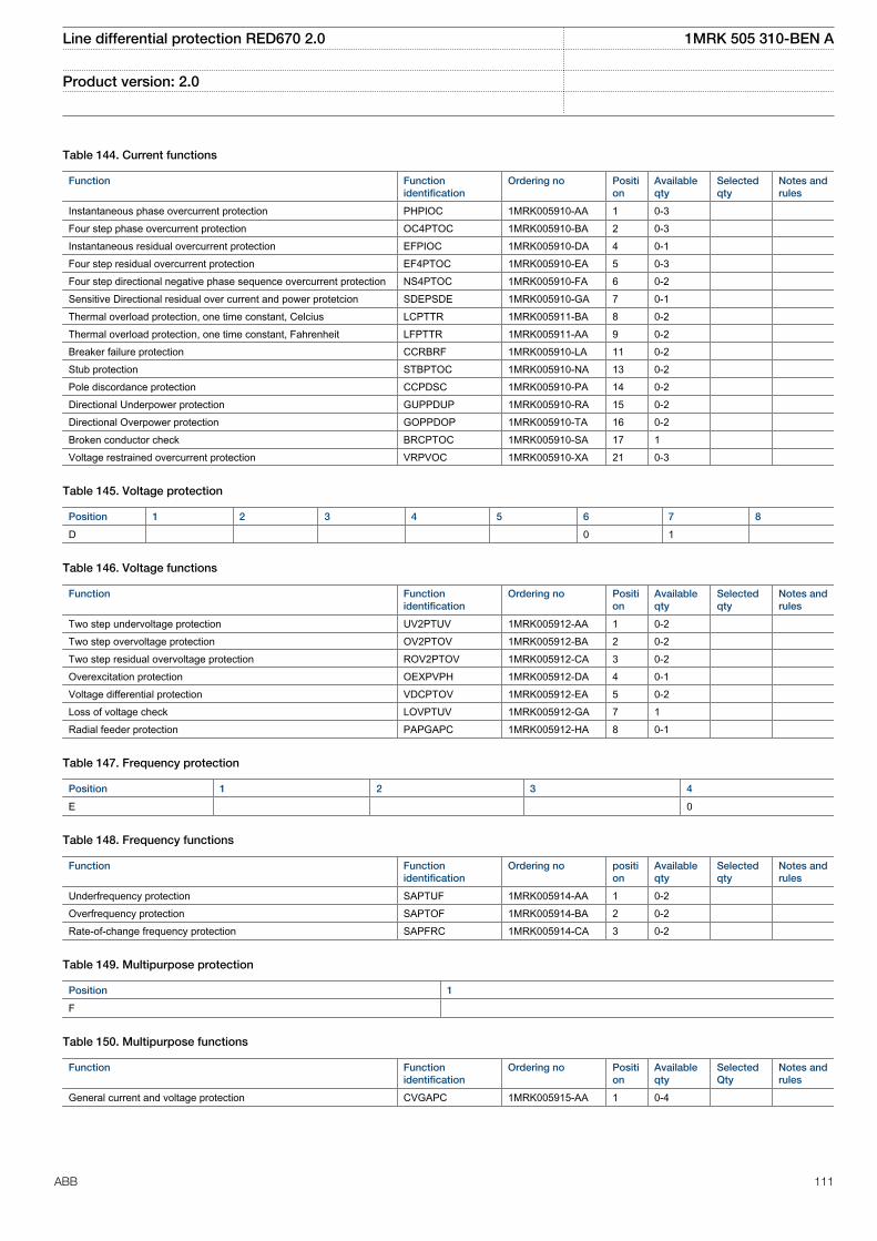
Table 144. Current functions
Function Functionidentification
Ordering no Position
Availableqty
Selectedqty
Notes andrules
Instantaneous phase overcurrent protection PHPIOC 1MRK005910-AA 1 0-3 Four step phase overcurrent protection OC4PTOC 1MRK005910-BA 2 0-3 Instantaneous residual overcurrent protection EFPIOC 1MRK005910-DA 4 0-1 Four step residual overcurrent protection EF4PTOC 1MRK005910-EA 5 0-3 Four step directional negative phase sequence overcurrent protection NS4PTOC 1MRK005910-FA 6 0-2 Sensitive Directional residual over current and power protetcion SDEPSDE 1MRK005910-GA 7 0-1 Thermal overload protection, one time constant, Celcius LCPTTR 1MRK005911-BA 8 0-2 Thermal overload protection, one time constant, Fahrenheit LFPTTR 1MRK005911-AA 9 0-2 Breaker failure protection CCRBRF 1MRK005910-LA 11 0-2 Stub protection STBPTOC 1MRK005910-NA 13 0-2 Pole discordance protection CCPDSC 1MRK005910-PA 14 0-2 Directional Underpower protection GUPPDUP 1MRK005910-RA 15 0-2 Directional Overpower protection GOPPDOP 1MRK005910-TA 16 0-2 Broken conductor check BRCPTOC 1MRK005910-SA 17 1 Voltage restrained overcurrent protection VRPVOC 1MRK005910-XA 21 0-3
Table 145. Voltage protection
Position 1 2 3 4 5 6 7 8
D 0 1
Table 146. Voltage functions
Function Functionidentification
Ordering no Position
Availableqty
Selectedqty
Notes andrules
Two step undervoltage protection UV2PTUV 1MRK005912-AA 1 0-2 Two step overvoltage protection OV2PTOV 1MRK005912-BA 2 0-2 Two step residual overvoltage protection ROV2PTOV 1MRK005912-CA 3 0-2 Overexcitation protection OEXPVPH 1MRK005912-DA 4 0-1 Voltage differential protection VDCPTOV 1MRK005912-EA 5 0-2 Loss of voltage check LOVPTUV 1MRK005912-GA 7 1 Radial feeder protection PAPGAPC 1MRK005912-HA 8 0-1
Table 147. Frequency protection
Position 1 2 3 4
E 0
Table 148. Frequency functions
Function Functionidentification
Ordering no position
Availableqty
Selectedqty
Notes andrules
Underfrequency protection SAPTUF 1MRK005914-AA 1 0-2 Overfrequency protection SAPTOF 1MRK005914-BA 2 0-2 Rate-of-change frequency protection SAPFRC 1MRK005914-CA 3 0-2
Table 149. Multipurpose protection
Position 1
F
Table 150. Multipurpose functions
Function Functionidentification
Ordering no Position
Availableqty
SelectedQty
Notes andrules
General current and voltage protection CVGAPC 1MRK005915-AA 1 0-4
Line differential protection RED670 2.0 1MRK 505 310-BEN A
Product version: 2.0
ABB 111
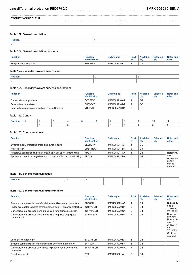
Table 151. General calculation
Position 1
S
Table 152. General calculation functions
Function Functionidentification
Ordering no Position
Availableqty
Selectedqty
Notes andrules
Frequency tracking filter SMAIHPAC 1MRK005915-KA 1 0-6
Table 153. Secondary system supervision
Position 1 2 3
G
Table 154. Secondary system supervision functions
Function Functionidentification
Ordering no Position
Availableqty
Selectedqty
Notes andrules
Current circuit supervison CCSSPVC 1MRK005916-AA 1 0-2 Fuse failure supervision FUFSPVC 1MRK005916-BA 2 0-3 Fuse failure supervision based on voltage difference VDSPVC 1MRK005916-CA 3 0-2
Table 155. Control
Position 1 2 3 4 5 6 7 8 9 10 11
H 0 0 0 0 0 0 0
Table 156. Control functions
Function Functionidentification
Ordering no Position
Availableqty
SelectedQty
Notes andrules
Synchrocheck, energizing check and synchronizing SESRSYN 1MRK005917-AA 1 0-2 Autorecloser SMBRREC 1MRK005917-BA 3 0-4 Apparatus control for single bay, max 8 app. (1CB) incl. Interlocking APC8 1MRK005917-AX 5 0-1 Note: Only
oneApparatuscontrolcan beordered.
Apparatus control for single bay, max 15 app. (2CBs) incl. Interlocking APC15 1MRK005917-BX 6 0-1
Table 157. Scheme communication
Position 1 2 3 4 5 6 7 8
K
Table 158. Scheme communication functions
Function Functionidentification
Ordering no Position
Availableqty
Selectedqty
Notes andrules
Scheme communication logic for distance or Overcurrent protection ZCPSCH 1MRK005920-AA 1 0-1 Note: Onlyone ofZCPSCH/ZC1PPSCH can beselectedNote: Onlyone ofZCRWPSCH/ZC1WPSCH to beselected
Phase segregated Scheme communication logic for distance protection ZC1PPSCH 1MRK005920-BA 2 0-1 Current reversal and weak-end infeed logic for distance protection ZCRWPSCH 1MRK005920-CA 3 0-1 Current reversal and weak-end infeed logic for phase segregatedcommunication
ZC1WPSCH 1MRK005920-DA 4 0-1
Local acceleration logic ZCLCPSCH 1MRK005920-EA 5 0-1 Scheme communication logic for residual overcurrent protection ECPSCH 1MRK005920-FA 6 0-1 Current reversal and weakend infeed logic for residual overcurrentprotection
ECRWPSCH 1MRK005920-GA 7 0-1
Direct transfer trip DTT 1MRK005921-AX 8 0-1
Line differential protection RED670 2.0 1MRK 505 310-BEN A
Product version: 2.0
112 ABB
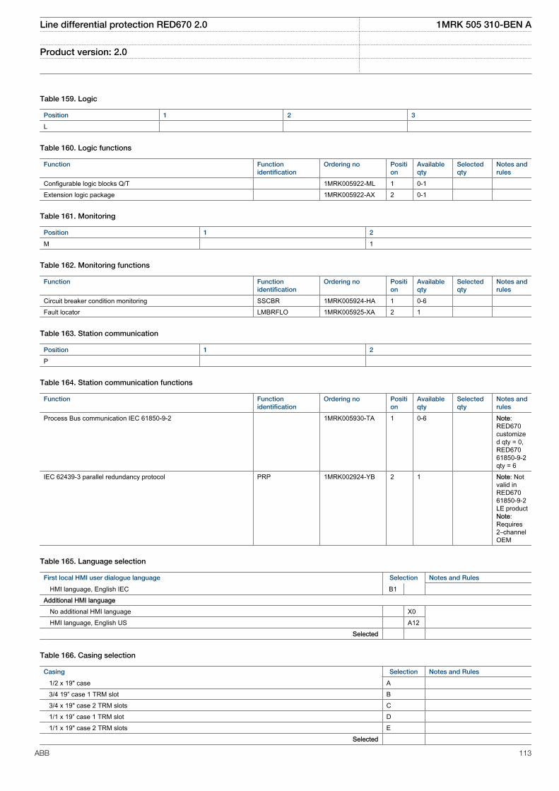
Table 159. Logic
Position 1 2 3
L
Table 160. Logic functions
Function Functionidentification
Ordering no Position
Availableqty
Selectedqty
Notes andrules
Configurable logic blocks Q/T 1MRK005922-ML 1 0-1 Extension logic package 1MRK005922-AX 2 0-1
Table 161. Monitoring
Position 1 2
M 1
Table 162. Monitoring functions
Function Functionidentification
Ordering no Position
Availableqty
Selectedqty
Notes andrules
Circuit breaker condition monitoring SSCBR 1MRK005924-HA 1 0-6 Fault locator LMBRFLO 1MRK005925-XA 2 1
Table 163. Station communication
Position 1 2
P
Table 164. Station communication functions
Function Functionidentification
Ordering no Position
Availableqty
Selectedqty
Notes andrules
Process Bus communication IEC 61850-9-2 1MRK005930-TA 1 0-6 Note:RED670customized qty = 0,RED67061850-9-2qty = 6
IEC 62439-3 parallel redundancy protocol PRP 1MRK002924-YB 2 1 Note: Notvalid inRED67061850-9-2LE productNote:Requires2–channelOEM
Table 165. Language selection
First local HMI user dialogue language Selection Notes and Rules
HMI language, English IEC B1 Additional HMI language No additional HMI language X0 HMI language, English US A12 Selected
Table 166. Casing selection
Casing Selection Notes and Rules
1/2 x 19" case A 3/4 19” case 1 TRM slot B 3/4 x 19" case 2 TRM slots C 1/1 x 19” case 1 TRM slot D 1/1 x 19" case 2 TRM slots E Selected
Line differential protection RED670 2.0 1MRK 505 310-BEN A
Product version: 2.0
ABB 113
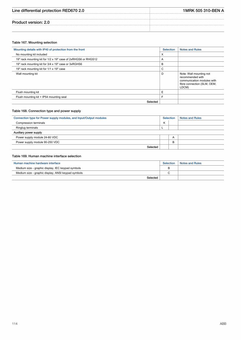
Table 167. Mounting selection
Mounting details with IP40 of protection from the front Selection Notes and Rules
No mounting kit included X 19" rack mounting kit for 1/2 x 19" case of 2xRHGS6 or RHGS12 A 19" rack mounting kit for 3/4 x 19" case or 3xRGHS6 B 19" rack mounting kit for 1/1 x 19" case C Wall mounting kit D Note: Wall mounting not
recommended withcommunication modules withfibre connection (SLM, OEM,LDCM)
Flush mounting kit E Flush mounting kit + IP54 mounting seal F Selected
Table 168. Connection type and power supply
Connection type for Power supply modules, and Input/Output modules Selection Notes and Rules
Compression terminals K Ringlug terminals L Auxiliary power supply Power supply module 24-60 VDC A Power supply module 90-250 VDC B Selected
Table 169. Human machine interface selection
Human machine hardware interface Selection Notes and Rules
Medium size - graphic display, IEC keypad symbols B Medium size - graphic display, ANSI keypad symbols C Selected
Line differential protection RED670 2.0 1MRK 505 310-BEN A
Product version: 2.0
114 ABB
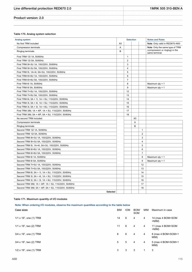
Table 170. Analog system selection
Analog system Selection Notes and Rules
No first TRM included X0 Note: Only valid in RED670–N00 Compression terminals A Note: Only the same type of TRM
(compression or ringlug) in thesame terminal. Ringlug terminals B
First TRM 12I 1A, 50/60Hz 1 First TRM 12I 5A, 50/60Hz 2 First TRM 9I+3U 1A, 100/220V, 50/60Hz 3 First TRM 9I+3U 5A, 100/220V, 50/60Hz 4 First TRM 5I, 1A+4I, 5A+3U, 100/220V, 50/60Hz 5 First TRM 6I+6U 1A, 100/220V, 50/60Hz 6 First TRM 6I+6U 5A, 100/220V, 50/60Hz 7 First TRM 6I 1A, 50/60Hz 8 Maximum qty = 1 First TRM 6I 5A, 50/60Hz 9 Maximum qty = 1 First TRM 7I+5U 1A, 100/220V, 50/60Hz 12 First TRM 7I+5U 5A, 100/220V, 50/60Hz 13 First TRM 6I, 5A + 1I, 1A + 5U, 110/220V, 50/60Hz 14 First TRM 3I, 5A + 4I, 1A + 5U, 110/220V, 50/60Hz 15 First TRM 3I, 5A + 3I, 1A + 6U, 110/220V, 50/60Hz 16 First TRM 3IM, 1A + 4IP, 1A + 5U, 110/220V, 50/60Hz 17 First TRM 3IM, 5A + 4IP, 5A + 5U, 110/220V, 50/60Hz 18 No second TRM included X0 Compression terminals A Ringlug terminals B Second TRM 12I 1A, 50/60Hz 1 Second TRM 12I 5A, 50/60Hz 2 Second TRM 9I+3U 1A, 100/220V, 50/60Hz 3 Second TRM 9I+3U 5A, 100/220V, 50/60Hz 4 Second TRM 5I, 1A+4I, 5A+3U, 100/220V, 50/60Hz 5 Second TRM 6I+6U 1A, 100/220V, 50/60Hz 6 Second TRM 6I+6U 5A, 100/220V, 50/60Hz 7 Second TRM 6I 1A, 50/60Hz 8 Maximum qty = 1 Second TRM 6I 5A, 50/60Hz 9 Maximum qty = 1 Second TRM 7I+5U 1A, 100/220V, 50/60Hz 12 Second TRM 7I+5U 5A, 100/220V, 50/60Hz 13 Second TRM 6I, 5A + 1I, 1A + 5U, 110/220V, 50/60Hz 14 Second TRM 3I, 5A + 4I, 1A + 5U, 110/220V, 50/60Hz 15 Second TRM 3I, 5A + 3I, 1A + 6U, 110/220V, 50/60Hz 16 Second TRM 3IM, 1A + 4IP, 1A + 5U, 110/220V, 50/60Hz 17 Second TRM 3IM, 5A + 4IP, 5A + 5U, 110/220V, 50/60Hz 18 Selected
Table 171. Maximum quantity of I/O modules
Note: When ordering I/O modules, observe the maximum quantities according to the table below
Case sizes BIM IOM BOM/SOM
MIM Maximum in case
1/1 x 19”, one (1) TRM 14 6 4 4 14 (max 4 BOM+SOM+MIM)
1/1 x 19”, two (2) TRM 11 6 4 4 11 (max 4 BOM+SOM+MIM)
3/4 x 19”, one (1) TRM 8 6 4 4 8 (max 4 BOM+SOM+1MIM)
3/4 x 19”, two (2) TRM 5 5 4 4 5 (max 4 BOM+SOM+1MIM)
1/2 x 19”, one (1) TRM 3 3 3 1 3
Line differential protection RED670 2.0 1MRK 505 310-BEN A
Product version: 2.0
ABB 115
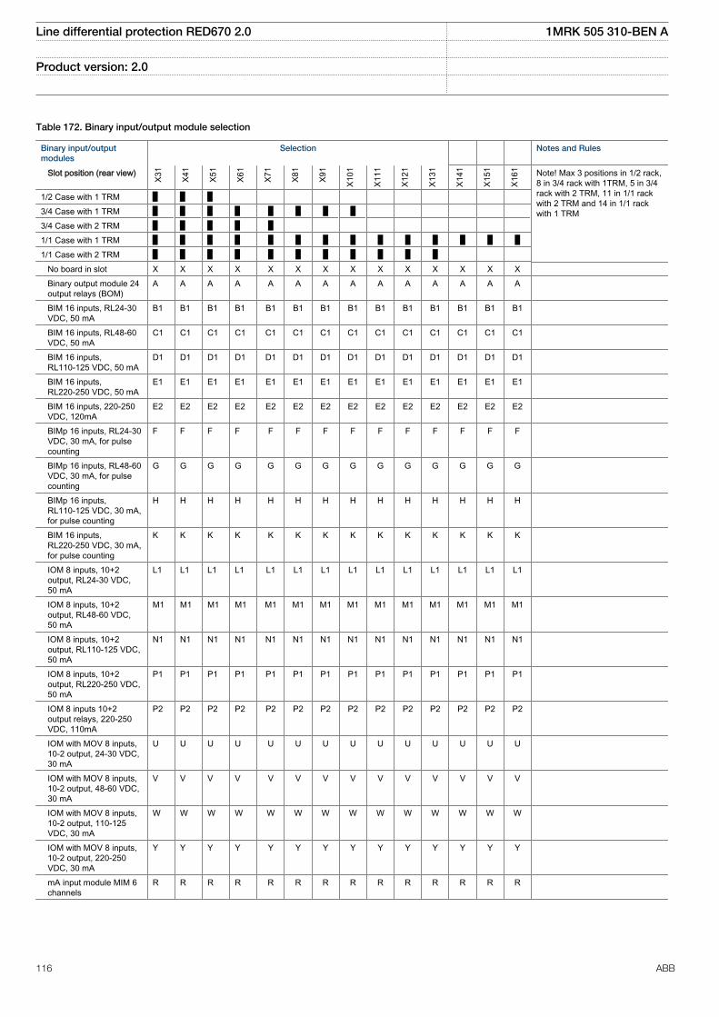
Table 172. Binary input/output module selection
Binary input/outputmodules
Selection Notes and Rules
Slot position (rear view)
X31
X41
X51
X61
X71
X81
X91
X101
X111
X121
X131
X141
X151
X161 Note! Max 3 positions in 1/2 rack,
8 in 3/4 rack with 1TRM, 5 in 3/4rack with 2 TRM, 11 in 1/1 rackwith 2 TRM and 14 in 1/1 rackwith 1 TRM
1/2 Case with 1 TRM 3/4 Case with 1 TRM 3/4 Case with 2 TRM 1/1 Case with 1 TRM 1/1 Case with 2 TRM No board in slot X X X X X X X X X X X X X X Binary output module 24
output relays (BOM)A A A A A A A A A A A A A A
BIM 16 inputs, RL24-30VDC, 50 mA
B1 B1 B1 B1 B1 B1 B1 B1 B1 B1 B1 B1 B1 B1
BIM 16 inputs, RL48-60VDC, 50 mA
C1 C1 C1 C1 C1 C1 C1 C1 C1 C1 C1 C1 C1 C1
BIM 16 inputs,RL110-125 VDC, 50 mA
D1 D1 D1 D1 D1 D1 D1 D1 D1 D1 D1 D1 D1 D1
BIM 16 inputs,RL220-250 VDC, 50 mA
E1 E1 E1 E1 E1 E1 E1 E1 E1 E1 E1 E1 E1 E1
BIM 16 inputs, 220-250VDC, 120mA
E2 E2 E2 E2 E2 E2 E2 E2 E2 E2 E2 E2 E2 E2
BIMp 16 inputs, RL24-30VDC, 30 mA, for pulsecounting
F F F F F F F F F F F F F F
BIMp 16 inputs, RL48-60VDC, 30 mA, for pulsecounting
G G G G G G G G G G G G G G
BIMp 16 inputs,RL110-125 VDC, 30 mA,for pulse counting
H H H H H H H H H H H H H H
BIM 16 inputs,RL220-250 VDC, 30 mA,for pulse counting
K K K K K K K K K K K K K K
IOM 8 inputs, 10+2output, RL24-30 VDC,50 mA
L1 L1 L1 L1 L1 L1 L1 L1 L1 L1 L1 L1 L1 L1
IOM 8 inputs, 10+2output, RL48-60 VDC,50 mA
M1 M1 M1 M1 M1 M1 M1 M1 M1 M1 M1 M1 M1 M1
IOM 8 inputs, 10+2output, RL110-125 VDC,50 mA
N1 N1 N1 N1 N1 N1 N1 N1 N1 N1 N1 N1 N1 N1
IOM 8 inputs, 10+2output, RL220-250 VDC,50 mA
P1 P1 P1 P1 P1 P1 P1 P1 P1 P1 P1 P1 P1 P1
IOM 8 inputs 10+2output relays, 220-250VDC, 110mA
P2 P2 P2 P2 P2 P2 P2 P2 P2 P2 P2 P2 P2 P2
IOM with MOV 8 inputs,10-2 output, 24-30 VDC,30 mA
U U U U U U U U U U U U U U
IOM with MOV 8 inputs,10-2 output, 48-60 VDC,30 mA
V V V V V V V V V V V V V V
IOM with MOV 8 inputs,10-2 output, 110-125VDC, 30 mA
W W W W W W W W W W W W W W
IOM with MOV 8 inputs,10-2 output, 220-250VDC, 30 mA
Y Y Y Y Y Y Y Y Y Y Y Y Y Y
mA input module MIM 6channels
R R R R R R R R R R R R R R
Line differential protection RED670 2.0 1MRK 505 310-BEN A
Product version: 2.0
116 ABB
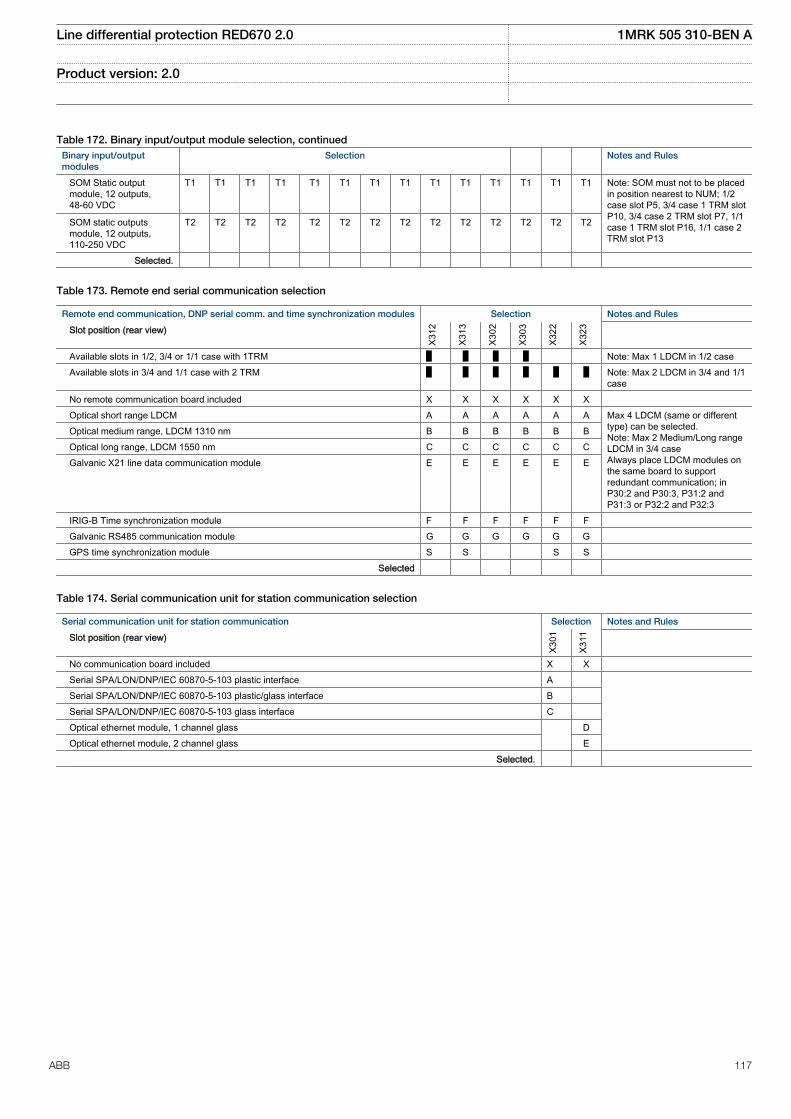
Table 172. Binary input/output module selection, continuedBinary input/outputmodules
Selection Notes and Rules
SOM Static outputmodule, 12 outputs,48-60 VDC
T1 T1 T1 T1 T1 T1 T1 T1 T1 T1 T1 T1 T1 T1 Note: SOM must not to be placedin position nearest to NUM; 1/2case slot P5, 3/4 case 1 TRM slotP10, 3/4 case 2 TRM slot P7, 1/1case 1 TRM slot P16, 1/1 case 2TRM slot P13
SOM static outputsmodule, 12 outputs,110-250 VDC
T2 T2 T2 T2 T2 T2 T2 T2 T2 T2 T2 T2 T2 T2
Selected.
Table 173. Remote end serial communication selection
Remote end communication, DNP serial comm. and time synchronization modules Selection Notes and Rules
Slot position (rear view)
X312
X313
X302
X303
X322
X323
Available slots in 1/2, 3/4 or 1/1 case with 1TRM Note: Max 1 LDCM in 1/2 case Available slots in 3/4 and 1/1 case with 2 TRM Note: Max 2 LDCM in 3/4 and 1/1
case No remote communication board included X X X X X X Optical short range LDCM A A A A A A Max 4 LDCM (same or different
type) can be selected.Note: Max 2 Medium/Long rangeLDCM in 3/4 caseAlways place LDCM modules onthe same board to supportredundant communication; inP30:2 and P30:3, P31:2 andP31:3 or P32:2 and P32:3
Optical medium range, LDCM 1310 nm B B B B B B Optical long range, LDCM 1550 nm C C C C C C Galvanic X21 line data communication module E E E E E E
IRIG-B Time synchronization module F F F F F F Galvanic RS485 communication module G G G G G G GPS time synchronization module S S S S Selected
Table 174. Serial communication unit for station communication selection
Serial communication unit for station communication Selection Notes and Rules
Slot position (rear view)
X301
X311
No communication board included X X Serial SPA/LON/DNP/IEC 60870-5-103 plastic interface A Serial SPA/LON/DNP/IEC 60870-5-103 plastic/glass interface B Serial SPA/LON/DNP/IEC 60870-5-103 glass interface C Optical ethernet module, 1 channel glass D Optical ethernet module, 2 channel glass E Selected.
Line differential protection RED670 2.0 1MRK 505 310-BEN A
Product version: 2.0
ABB 117
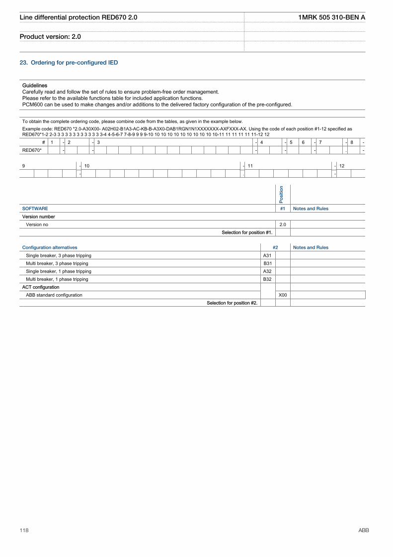
23. Ordering for pre-configured IED
GuidelinesCarefully read and follow the set of rules to ensure problem-free order management.Please refer to the available functions table for included application functions.PCM600 can be used to make changes and/or additions to the delivered factory configuration of the pre-configured.
To obtain the complete ordering code, please combine code from the tables, as given in the example below.Example code: RED670 *2.0-A30X00- A02H02-B1A3-AC-KB-B-A3X0-DAB1RGN1N1XXXXXXX-AXFXXX-AX. Using the code of each position #1-12 specified asRED670*1-2 2-3 3 3 3 3 3 3 3 3 3 3 3 3-4 4-5-6-7 7-8-9 9 9 9-10 10 10 10 10 10 10 10 10 10 10-11 11 11 11 11 11-12 12
# 1 - 2 - 3 - 4 - 5 6 - 7 - 8 -RED670* - - - - - . -
9 - 10 - 11 - 12 - . -
Po
sitio
n
SOFTWARE #1 Notes and Rules
Version number Version no 2.0
Selection for position #1.
Configuration alternatives #2 Notes and Rules
Single breaker, 3 phase tripping A31 Multi breaker, 3 phase tripping B31 Single breaker, 1 phase tripping A32 Multi breaker, 1 phase tripping B32 ACT configuration ABB standard configuration X00 Selection for position #2.
Line differential protection RED670 2.0 1MRK 505 310-BEN A
Product version: 2.0
118 ABB
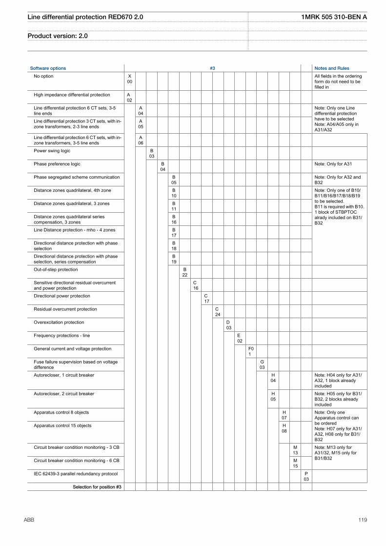
Software options #3 Notes and Rules
No option X00
All fields in the orderingform do not need to befilled in
High impedance differential protection A02
Line differential protection 6 CT sets, 3-5line ends
A04
Note: Only one Linedifferential protectionhave to be selectedNote: A04/A05 only inA31/A32
Line differential protection 3 CT sets, with in-zone transformers, 2-3 line ends
A05
Line differential protection 6 CT sets, with in-zone transformers, 3-5 line ends
A06
Power swing logic B03
Phase preference logic B04
Note: Only for A31
Phase segregated scheme communication B05
Note: Only for A32 andB32
Distance zones quadrilateral, 4th zone B10
Note: Only one of B10/B11/B16/B17/B18/B19to be selected.B11 is required with B10.1 block of STBPTOCalrady included on B31/B32
Distance zones quadrilateral, 3 zones B11
Distance zones quadrilateral seriescompensation, 3 zones
B16
Line Distance protection - mho - 4 zones B17
Directional distance protection with phaseselection
B18
Directional distance protection with phaseselection, series compensation
B19
Out-of-step protection B22
Sensitive directional residual overcurrentand power protection
C16
Directional power protection C17
Residual overcurrent protection C24
Overexcitation protection D03
Frequency protections - line E02
General current and voltage protection F01
Fuse failure supervision based on voltagedifference
G03
Autorecloser, 1 circuit breaker H04
Note: H04 only for A31/A32, 1 block alreadyincluded
Autorecloser, 2 circuit breaker H05
Note: H05 only for B31/B32, 2 blocks alreadyincluded
Apparatus control 8 objects H07
Note: Only oneApparatus control canbe orderedNote: H07 only for A31/A32, H08 only for B31/B32
Apparatus control 15 objects H08
Circuit breaker condition monitoring - 3 CB M13
Note: M13 only forA31/32, M15 only forB31/B32 Circuit breaker condition monitoring - 6 CB M
15
IEC 62439-3 parallel redundancy protocol P03
Selection for position #3
Line differential protection RED670 2.0 1MRK 505 310-BEN A
Product version: 2.0
ABB 119
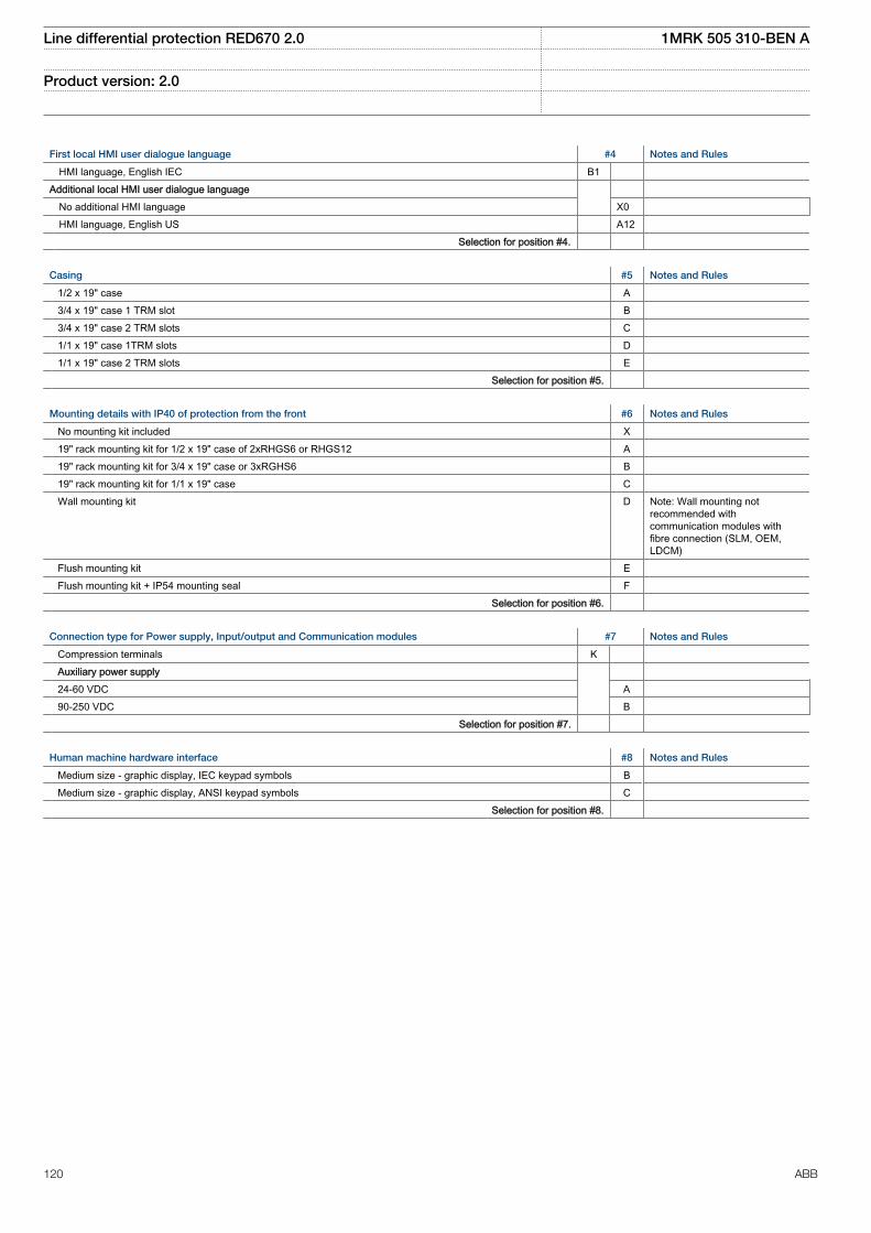
First local HMI user dialogue language #4 Notes and Rules
HMI language, English IEC B1 Additional local HMI user dialogue language No additional HMI language X0 HMI language, English US A12 Selection for position #4.
Casing #5 Notes and Rules
1/2 x 19" case A 3/4 x 19" case 1 TRM slot B 3/4 x 19" case 2 TRM slots C 1/1 x 19" case 1TRM slots D 1/1 x 19" case 2 TRM slots E Selection for position #5.
Mounting details with IP40 of protection from the front #6 Notes and Rules
No mounting kit included X 19" rack mounting kit for 1/2 x 19" case of 2xRHGS6 or RHGS12 A 19" rack mounting kit for 3/4 x 19" case or 3xRGHS6 B 19" rack mounting kit for 1/1 x 19" case C Wall mounting kit D Note: Wall mounting not
recommended withcommunication modules withfibre connection (SLM, OEM,LDCM)
Flush mounting kit E Flush mounting kit + IP54 mounting seal F Selection for position #6.
Connection type for Power supply, Input/output and Communication modules #7 Notes and Rules
Compression terminals K Auxiliary power supply 24-60 VDC A 90-250 VDC B Selection for position #7.
Human machine hardware interface #8 Notes and Rules
Medium size - graphic display, IEC keypad symbols B Medium size - graphic display, ANSI keypad symbols C Selection for position #8.
Line differential protection RED670 2.0 1MRK 505 310-BEN A
Product version: 2.0
120 ABB

Analog input system #9 Notes and Rules
Compression terminals A Ringlug terminals B First TRM, 6I+6U 1A, 100/220V 6 First TRM, 6I+6U 5A, 100/220V 7 First TRM, 3I, 5A + 3I, 1A + 6U, 110/220V 16 Note: Only for A31 and A32 No second TRM included X0 Compression terminals A Ringlug terminals B Second TRM, 9I+3U 1A, 110/220V 3 Second TRM, 9I+3U 5A, 110/220V 4 Second TRM, 5I, 1A+4I, 5A+3U, 110/220V 5 Second TRM, 6I+6U, 1A, 110/220V 6 Second TRM, 6I+6U, 5A, 110/220V 7 Second TRM, 6I, 1A, 110/220V 8 Second TRM, 6I, 5A, 5A, 110/220V 9 Second TRM, 7I+5U 1A, 110/220V 12 Second TRM, 7I+5U 5A, 110/220V 13 Second TRM, 3I, 5A + 3I, 1A + 6U, 110/220V 16 Note: Only for A31 and A32 Selection for position #9.
Line differential protection RED670 2.0 1MRK 505 310-BEN A
Product version: 2.0
ABB 121
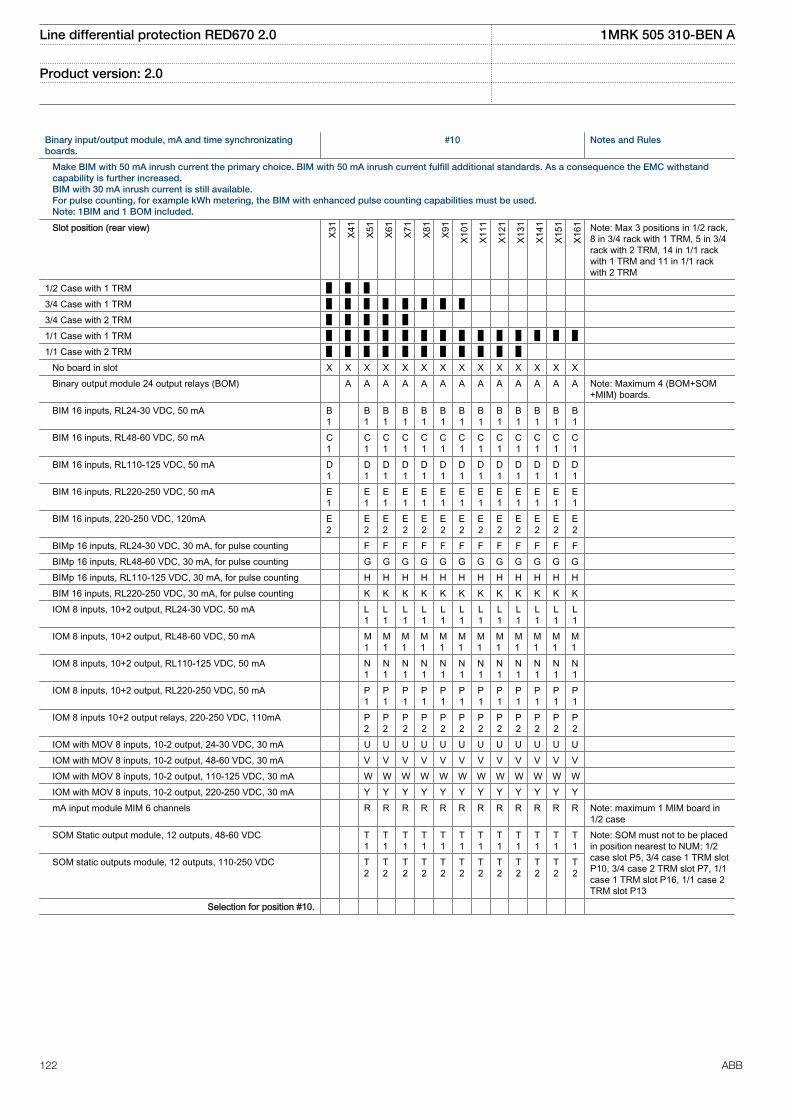
Binary input/output module, mA and time synchronizatingboards.
#10 Notes and Rules
Make BIM with 50 mA inrush current the primary choice. BIM with 50 mA inrush current fulfill additional standards. As a consequence the EMC withstandcapability is further increased.BIM with 30 mA inrush current is still available.For pulse counting, for example kWh metering, the BIM with enhanced pulse counting capabilities must be used.Note: 1BIM and 1 BOM included.
Slot position (rear view)
X31
X41
X51
X61
X71
X81
X91
X101
X111
X121
X131
X141
X151
X161 Note: Max 3 positions in 1/2 rack,
8 in 3/4 rack with 1 TRM, 5 in 3/4rack with 2 TRM, 14 in 1/1 rackwith 1 TRM and 11 in 1/1 rackwith 2 TRM
1/2 Case with 1 TRM 3/4 Case with 1 TRM 3/4 Case with 2 TRM 1/1 Case with 1 TRM 1/1 Case with 2 TRM No board in slot X X X X X X X X X X X X X X Binary output module 24 output relays (BOM) A A A A A A A A A A A A A Note: Maximum 4 (BOM+SOM
+MIM) boards. BIM 16 inputs, RL24-30 VDC, 50 mA B
1 B
1B1
B1
B1
B1
B1
B1
B1
B1
B1
B1
B1
BIM 16 inputs, RL48-60 VDC, 50 mA C1
C1
C1
C1
C1
C1
C1
C1
C1
C1
C1
C1
C1
BIM 16 inputs, RL110-125 VDC, 50 mA D1
D1
D1
D1
D1
D1
D1
D1
D1
D1
D1
D1
D1
BIM 16 inputs, RL220-250 VDC, 50 mA E1
E1
E1
E1
E1
E1
E1
E1
E1
E1
E1
E1
E1
BIM 16 inputs, 220-250 VDC, 120mA E2
E2
E2
E2
E2
E2
E2
E2
E2
E2
E2
E2
E2
BIMp 16 inputs, RL24-30 VDC, 30 mA, for pulse counting F F F F F F F F F F F F BIMp 16 inputs, RL48-60 VDC, 30 mA, for pulse counting G G G G G G G G G G G G BIMp 16 inputs, RL110-125 VDC, 30 mA, for pulse counting H H H H H H H H H H H H BIM 16 inputs, RL220-250 VDC, 30 mA, for pulse counting K K K K K K K K K K K K IOM 8 inputs, 10+2 output, RL24-30 VDC, 50 mA L
1L1
L1
L1
L1
L1
L1
L1
L1
L1
L1
L1
IOM 8 inputs, 10+2 output, RL48-60 VDC, 50 mA M1
M1
M1
M1
M1
M1
M1
M1
M1
M1
M1
M1
IOM 8 inputs, 10+2 output, RL110-125 VDC, 50 mA N1
N1
N1
N1
N1
N1
N1
N1
N1
N1
N1
N1
IOM 8 inputs, 10+2 output, RL220-250 VDC, 50 mA P1
P1
P1
P1
P1
P1
P1
P1
P1
P1
P1
P1
IOM 8 inputs 10+2 output relays, 220-250 VDC, 110mA P2
P2
P2
P2
P2
P2
P2
P2
P2
P2
P2
P2
IOM with MOV 8 inputs, 10-2 output, 24-30 VDC, 30 mA U U U U U U U U U U U U IOM with MOV 8 inputs, 10-2 output, 48-60 VDC, 30 mA V V V V V V V V V V V V IOM with MOV 8 inputs, 10-2 output, 110-125 VDC, 30 mA W W W W W W W W W W W W IOM with MOV 8 inputs, 10-2 output, 220-250 VDC, 30 mA Y Y Y Y Y Y Y Y Y Y Y Y mA input module MIM 6 channels R R R R R R R R R R R R Note: maximum 1 MIM board in
1/2 case SOM Static output module, 12 outputs, 48-60 VDC T
1T1
T1
T1
T1
T1
T1
T1
T1
T1
T1
T1
Note: SOM must not to be placedin position nearest to NUM; 1/2case slot P5, 3/4 case 1 TRM slotP10, 3/4 case 2 TRM slot P7, 1/1case 1 TRM slot P16, 1/1 case 2TRM slot P13
SOM static outputs module, 12 outputs, 110-250 VDC T2
T2
T2
T2
T2
T2
T2
T2
T2
T2
T2
T2
Selection for position #10.
Line differential protection RED670 2.0 1MRK 505 310-BEN A
Product version: 2.0
122 ABB
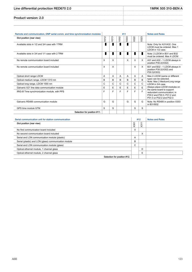
Remote end communication, DNP serial comm. and time synchronization modules #11 Notes and Rules
Slot position (rear view)
X312
X313
X302
X303
X322
X323
Available slots in 1/2 and 3/4 case with 1TRM Note: Only for A31/A32. OneLDCM must be ordered. Max 1LDCM in 1/2 case.
Available slots in 3/4 and 1/1 case with 2 TRM Note: 2 LDCM in B31 and B32must be ordered. Max 4 LDCM
No remote communication board included X X X X X A31 and A32 - 1 LDCM always inposition P30:2(X302)
No remote communication board included X X X X B31 and B32 - 1 LDCM always inposition P30:2(X302) andP30:3(X303)
Optical short range LDCM A A A A A A Max 4 LDCM (same or differenttype) can be selected.Note: Max 2 Medium/Long rangeLDCM in 3/4 caseAlways place LDCM modules onthe same board to supportredundant communication; inP30:2 and P30:3, P31:2 andP31:3 or P32:2 and P32:3
Optical medium range, LDCM 1310 nm B B B B B B Optical long range, LDCM 1550 nm C C C C C C Galvanic X21 line data communication module E E E E E E IRIG-B Time synchronization module, with PPS F F F F F F
Galvanic RS485 communication module G G G G G Note: No RS485 in position X303in B31/B32
GPS time module GTM S S S S Selection for position #11.
Serial communication unit for station communication #12 Notes and Rules
Slot position (rear view)
X301
X311
No first communication board included X No second communication board included X Serial and LON communication module (plastic) A Serial (plastic) and LON (glass) communication module B Serial and LON communication module (glass) C Optical ethernet module, 1 channel glass D Optical ethernet module, 2 channel glass E Selection for position #12.
Line differential protection RED670 2.0 1MRK 505 310-BEN A
Product version: 2.0
ABB 123
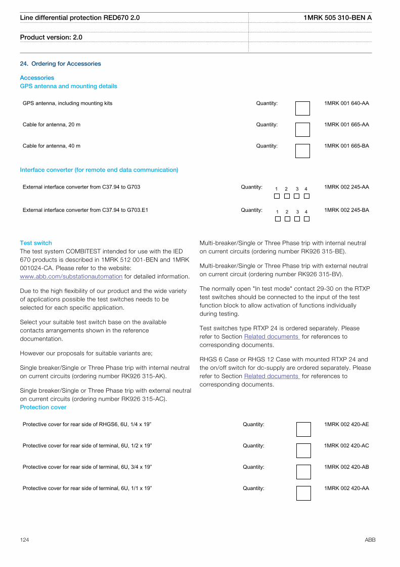
24. Ordering for Accessories
AccessoriesGPS antenna and mounting details
GPS antenna, including mounting kits Quantity: 1MRK 001 640-AA
Cable for antenna, 20 m Quantity: 1MRK 001 665-AA
Cable for antenna, 40 m Quantity: 1MRK 001 665-BA
Interface converter (for remote end data communication)
External interface converter from C37.94 to G703 Quantity: 1 2 3 4 1MRK 002 245-AA
External interface converter from C37.94 to G703.E1 Quantity: 1 2 3 4 1MRK 002 245-BA
Test switchThe test system COMBITEST intended for use with the IED670 products is described in 1MRK 512 001-BEN and 1MRK001024-CA. Please refer to the website:www.abb.com/substationautomation for detailed information.
Due to the high flexibility of our product and the wide varietyof applications possible the test switches needs to beselected for each specific application.
Select your suitable test switch base on the availablecontacts arrangements shown in the referencedocumentation.
However our proposals for suitable variants are;
Single breaker/Single or Three Phase trip with internal neutralon current circuits (ordering number RK926 315-AK).
Single breaker/Single or Three Phase trip with external neutralon current circuits (ordering number RK926 315-AC).
Multi-breaker/Single or Three Phase trip with internal neutralon current circuits (ordering number RK926 315-BE).
Multi-breaker/Single or Three Phase trip with external neutralon current circuit (ordering number RK926 315-BV).
The normally open "In test mode" contact 29-30 on the RTXPtest switches should be connected to the input of the testfunction block to allow activation of functions individuallyduring testing.
Test switches type RTXP 24 is ordered separately. Pleaserefer to Section Related documents for references tocorresponding documents.
RHGS 6 Case or RHGS 12 Case with mounted RTXP 24 andthe on/off switch for dc-supply are ordered separately. Pleaserefer to Section Related documents for references tocorresponding documents.
Protection cover
Protective cover for rear side of RHGS6, 6U, 1/4 x 19” Quantity: 1MRK 002 420-AE
Protective cover for rear side of terminal, 6U, 1/2 x 19” Quantity: 1MRK 002 420-AC
Protective cover for rear side of terminal, 6U, 3/4 x 19” Quantity: 1MRK 002 420-AB
Protective cover for rear side of terminal, 6U, 1/1 x 19” Quantity: 1MRK 002 420-AA
Line differential protection RED670 2.0 1MRK 505 310-BEN A
Product version: 2.0
124 ABB
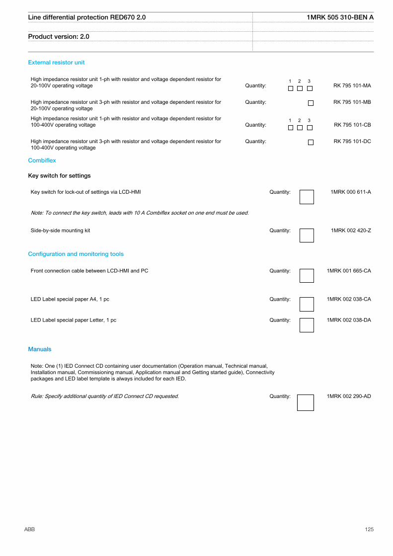
External resistor unit
High impedance resistor unit 1-ph with resistor and voltage dependent resistor for20-100V operating voltage
Quantity:
1 2 3 RK 795 101-MA
High impedance resistor unit 3-ph with resistor and voltage dependent resistor for20-100V operating voltage
Quantity: RK 795 101-MB
High impedance resistor unit 1-ph with resistor and voltage dependent resistor for100-400V operating voltage
Quantity:
1 2 3 RK 795 101-CB
High impedance resistor unit 3-ph with resistor and voltage dependent resistor for100-400V operating voltage
Quantity: RK 795 101-DC
Combiflex
Key switch for settings
Key switch for lock-out of settings via LCD-HMI Quantity: 1MRK 000 611-A
Note: To connect the key switch, leads with 10 A Combiflex socket on one end must be used.
Side-by-side mounting kit Quantity: 1MRK 002 420-Z
Configuration and monitoring tools
Front connection cable between LCD-HMI and PC Quantity: 1MRK 001 665-CA
LED Label special paper A4, 1 pc Quantity: 1MRK 002 038-CA
LED Label special paper Letter, 1 pc Quantity: 1MRK 002 038-DA
Manuals
Note: One (1) IED Connect CD containing user documentation (Operation manual, Technical manual,Installation manual, Commissioning manual, Application manual and Getting started guide), Connectivitypackages and LED label template is always included for each IED.
Rule: Specify additional quantity of IED Connect CD requested. Quantity: 1MRK 002 290-AD
Line differential protection RED670 2.0 1MRK 505 310-BEN A
Product version: 2.0
ABB 125
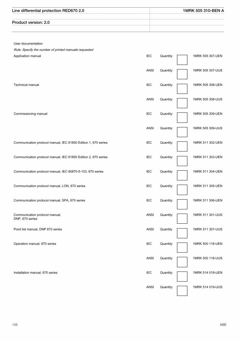
User documentation
Rule: Specify the number of printed manuals requested
Application manual IEC Quantity: 1MRK 505 307-UEN
ANSI Quantity: 1MRK 505 307-UUS
Technical manual IEC Quantity: 1MRK 505 308-UEN
ANSI Quantity: 1MRK 505 308-UUS
Commissioning manual IEC Quantity: 1MRK 505 309-UEN
ANSI Quantity: 1MRK 505 309-UUS
Communication protocol manual, IEC 61850 Edition 1, 670 series IEC Quantity: 1MRK 511 302-UEN
Communication protocol manual, IEC 61850 Edition 2, 670 series IEC Quantity: 1MRK 511 303-UEN
Communication protocol manual, IEC 60870-5-103, 670 series IEC Quantity: 1MRK 511 304-UEN
Communication protocol manual, LON, 670 series IEC Quantity: 1MRK 511 305-UEN
Communication protocol manual, SPA, 670 series IEC Quantity: 1MRK 511 306-UEN
Communication protocol manual,DNP, 670 series
ANSI Quantity: 1MRK 511 301-UUS
Point list manual, DNP 670 series ANSI Quantity 1MRK 511 307-UUS
Operation manual, 670 series IEC Quantity: 1MRK 500 118-UEN
ANSI Quantity: 1MRK 500 118-UUS
Installation manual, 670 series IEC Quantity: 1MRK 514 019-UEN
ANSI Quantity: 1MRK 514 019-UUS
Line differential protection RED670 2.0 1MRK 505 310-BEN A
Product version: 2.0
126 ABB
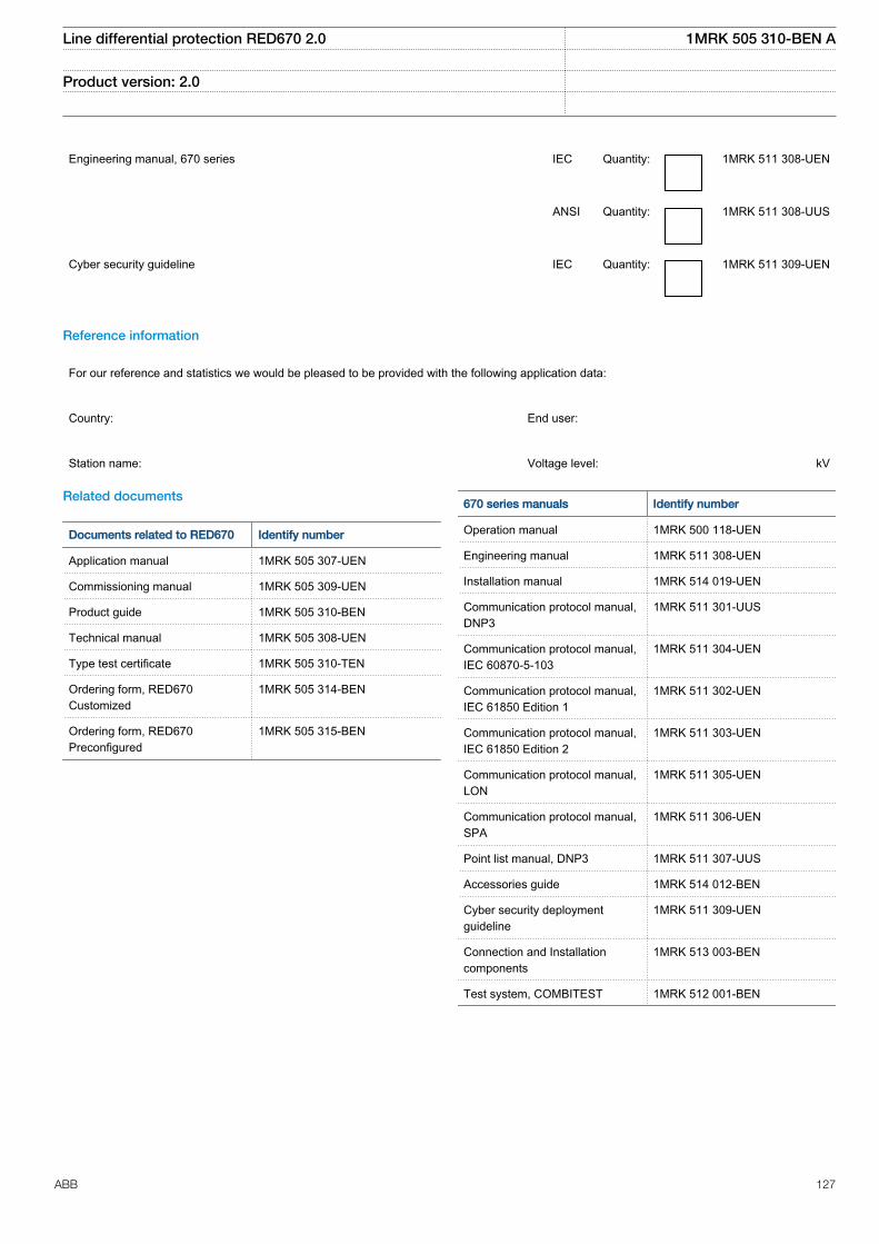
Engineering manual, 670 series IEC Quantity: 1MRK 511 308-UEN
ANSI Quantity: 1MRK 511 308-UUS
Cyber security guideline IEC Quantity: 1MRK 511 309-UEN
Reference information
For our reference and statistics we would be pleased to be provided with the following application data:
Country: End user:
Station name: Voltage level: kV
Related documents
Documents related to RED670 Identify number
Application manual 1MRK 505 307-UEN
Commissioning manual 1MRK 505 309-UEN
Product guide 1MRK 505 310-BEN
Technical manual 1MRK 505 308-UEN
Type test certificate 1MRK 505 310-TEN
Ordering form, RED670Customized
1MRK 505 314-BEN
Ordering form, RED670Preconfigured
1MRK 505 315-BEN
670 series manuals Identify number
Operation manual 1MRK 500 118-UEN
Engineering manual 1MRK 511 308-UEN
Installation manual 1MRK 514 019-UEN
Communication protocol manual,DNP3
1MRK 511 301-UUS
Communication protocol manual,IEC 60870-5-103
1MRK 511 304-UEN
Communication protocol manual,IEC 61850 Edition 1
1MRK 511 302-UEN
Communication protocol manual,IEC 61850 Edition 2
1MRK 511 303-UEN
Communication protocol manual,LON
1MRK 511 305-UEN
Communication protocol manual,SPA
1MRK 511 306-UEN
Point list manual, DNP3 1MRK 511 307-UUS
Accessories guide 1MRK 514 012-BEN
Cyber security deploymentguideline
1MRK 511 309-UEN
Connection and Installationcomponents
1MRK 513 003-BEN
Test system, COMBITEST 1MRK 512 001-BEN
Line differential protection RED670 2.0 1MRK 505 310-BEN A
Product version: 2.0
ABB 127

128

Contact us
ABB ABSubstation Automation ProductsSE-721 59 Västerås, SwedenPhone +46 (0) 21 32 50 00Fax +46 (0) 21 14 69 18
www.abb.com/substationautomation
1MR
K 5
05 3
10-B
EN
A©
Cop
yrig
ht 2
014
AB
B. A
ll rig
hts
rese
rved
.


