Embed Size (px)
Citation preview
1
1. INTRODUCTION
Water supply companies and authorized installation companies undertake theimportant task of providing the consumers with drinking water. The water qualitymust be ensured from the water treatment side up to the point of supply. The PublicHealth Departments are responsible for monitoring the adherence to the qualityrequirements. The work of water supply companies and plumbers is thus subject toan official surveillance.
A hygienically perfect water supplydepends on a large number of factors. Amajor point is the protection of thedrinking water in the pipe system againstcontamination by non-drinking water.Possible protective methods areformulated in the national DIN 1988-4. Inparallel to that standard, DIN EN 1717,which deals with this topic too, is alreadyvalid.
The following pages discuss the problemsthat arise in drinking water installations,and compare the standards for theprotection of the drinking water. Inaddition to a presentation of the functionand the installation of safety fittings, theirsituation-related selection is one of themain topics. A very imporant point is alsothe contractual agreement, since thestandards cannot both be the basis of acontract.
This manual is intended to provideinformation and assistance for the protection of the drinking water in practicalaplications. Important installation and selection criteria are clearly listed in tables. Thisshall enable the reader to determine quickly and safely the necessary safety fitting onsite.
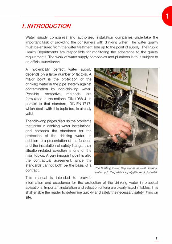
The Drinking Water Regulations request drinkingwater up to the point of supply (Figure: J. Scheele)
1

2
1
3
2. THE SIGNIFICANCE OF THE DRINKING WATERREGULATIONS FOR DESIGNERS AND PLUMBERS
All creatures on the earth substantially consist of water, and are unable to survivewitout water.
A drinking water expert who starts a discussion with the consumers of the preciousliquid gets the impression that these consumers are not aware of the fundamentalsignificance of this substance. And you can't even blame the water consumers forthis "ignorance". In Germany, water is omnipresent. Since it is always available, it istaken for granted. A matter of course, however, is nothing special in theunderstanding of the consumer.
Water - omnipresent
The role of the water in the daily life becomes obvious when the water is shut downin a building - for repair purposes, for example. It does not even take 30 minutes untilthe first inhabitant comes down in the basement asking when the supply shortage willbe over. While the inhabitant will presumably ask for "water", the expert mustdifferentiate a little bit more clearly. The substance delivered to the parlour is not justwater - it is drinking water.
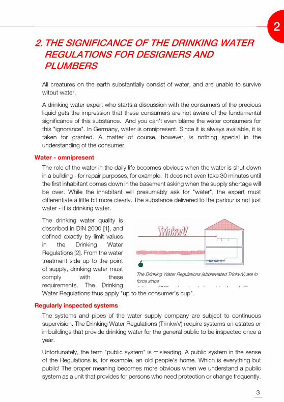
The drinking water quality isdescribed in DIN 2000 [1], anddefined exactly by limit valuesin the Drinking WaterRegulations [2]. From the watertreatment side up to the pointof supply, drinking water mustcomply with theserequirements. The DrinkingWater Regulations thus apply "up to the consumer's cup".
Regularly inspected systems
The systems and pipes of the water supply company are subject to continuoussupervision. The Drinking Water Regulations (TrinkwV) require systems on estates orin buildings that provide drinking water for the general public to be inspected once ayear.
Unfortunately, the term "public system" is misleading. A public system in the senseof the Regulations is, for example, an old people's home. Which is everything butpublic! The proper meaning becomes more obvious when we understand a publicsystem as a unit that provides for persons who need protection or change frequently.
The Drinking Water Regulations (abbreviated TrinkwV) are inforce since 1 J 2003 d l t th i t f l (Fi
2

4
Persons needing protection include children, ill or elderly persons since thesepersons are assumed to have a restricted physicogenic defensive power. Frequentlychanging groups of people can be found in restaurants or hotels, for example.
If a guest catches an infection here, he or she probably moved on already to adifferent hotel when the first symptoms of a disease become apparent. Localizationthus becomes a time-consuming and awkward task. This shows the necessity ofregular yearly inpections. If there are no reasons for major complaints inside asurveillance period of four years, defining longer inspection intervals is at thediscretion of the Public Healt Department. However, even then the inspection periodshould not be longer than two years.
Sporadically inspected systems
The number of people in a residential building who suffer from a weakend immunesystem is not usually above average. Furthermore, there is a more or less invariablegroup of persons in such a building. The allocation of cause and effect in the event ofa water-related desease (such as a legionella infection) is easy here. Authoritiestherefore request an inspection of the systems in private areas only if there seems tobe a reason for it. However, this situation can arise faster that expected: Aninspection is due if one of the inhabitants of a house addresses the Public HealthDepartment, expressing a concern about the quality of the drinking water.
No right of continuance for drinking water systems
The Public Health Department merelyorder the inspection, they do not carrythem out. The owner of the drinkingwater system must initiate theexamination. The Public HealthDepartment only accepts the result ofthe examination if the laboratory taskedwith carrying out the examination hasbeen approved for performing allnecessary inspections. This is called anaccredited laboratory. The operator ofthe drinking water system must notifythe Public Health Department of theresult of the examination inside of twoweeks after the samples were taken.
The Public Health Department must be notified immediately if the examination yieldsthe result that the water gives reasons for complaint. The Public Health Departmentthen decides on the actions to be taken. In some cases, eliminating such a causemeans restructuring the drinking water system.
Although there is a constructional right of continuance for old systems, this cannot
Even if everything was built according to theapplicable rules - there is no right of continuance fordrinking water systems (Figure: J. Scheele)
2
5
expediently be employed. The Drinking Water Regulations do not describe thestructure of a drinking water pipe - they define the quality requirements for thedrinking water that comes out of this pipe. The regulations apply to food, not to aconstructional system. If a pipe was installed according to the state-of-the-art validat the time of installation, and the quality of today's drinking water has deteriorated,in terms of building regulations the pipe is actually protected by the right ofcontinuance. However, it may no longer be used as a drinking water pipe.
People must have drinking water for personal hygiene, food preparation and cleaningdishes and washing. Consequently, the operator can not just declare the poor pipesin his or her house as domestic water pipes. There is need for action. Who does notact commits an offence: A person who intentionally provides water that does notcomply with the Drinking Water Regulations as drinking water to a third party actsnegligently. According to the Law for the Protection Against Infections, this ispunished with a prison sentence up to one year or a fine.
Mistakes no longer go undetected
Mistakes that were made when the drinking water system was designed or installed,are frequently the reason of a poor drinking water quality. Since installation inresidential buildings were not subject to official inspections until 2003, these mistakesremained undetected for a long time.
Today, the drinking water systems of the building are included in the scope of controlof the Drinking Water Regulations. This drastically reduced the probability of planningand installation mistakes remaining undetected. In first instance, a mistake revealedduring an inspection is the problem of the system operator. After all, he or she hascontrol over the system. However, the operator is usually a layman. This is why hehad his drinking water system set up by an expert. Consequently, he can assume thatthe expert designed everything such that there will permanently be drinking wateravailable at the points of supply. If it emerges that this is not the case, the contractfor services was not fulfilled: The order was "constructing a drinking water system".This fact results in civil claims against the performing specialist firm.
In this context, "discussing the price" will not do. A drinking water system that doesnot supply drinking water is useless. The specialist firm must modify it such that itfulfills its intended purpose. The resulting costs can be considerable. This means: Asituation-related implementation of the Technical Rules is indispensable whenbuilding drinking water plants.
2

6
2
7
3. RISKS FOR THE DRINKING WATER SUPPLY
As described above, the perfect quality of the drinking water must be maintained upto the points of supply. Preventing the infiltration of non-drinking water into thedrinking water system is a major prerequisite. The available protective measures andthe proper selection of these measures are the main topics of this manual. Correctlyused safety fittings, however, do not prove sufficient to ensure the drinking waterquality in a house installation. If mistakes are made when a system is planned andinstalled, the drinking water is also jeopardized when non-drinking water cannotpenetrate the system. Let's have a look at some typical installations that do notexactly contribute to maintaining the quality.
The material
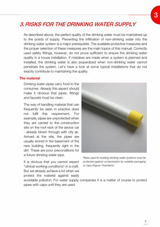
Drinking water pipes carry food to theconsumer. Already this aspect shouldmake it obvious that pipes, fittingsand faucets must be clean.
The way of handling material that canfrequently be seen in practice doesnot fulfil this requirement. Forexample, pipes are unprotected whenthey are carried to the constructionsite on the roof rack of the sevice car- already blown through with city air.Arrived at the site, the pipes areusually stored in the basement of thenew building, frequently right in thedirt. These are poor preconditions fora future drinking water pipe.
It is obvious that you cannot expect"clinical working conditions" in a craft.But we already achieve a lot when weprotect the material against easilyavoidable pollution. For water supply companies it is a matter of course to protectpipes with caps until they are used.
Pipes used for building drinking water systems must beprotected against contamination by suitable packagingor caps (Figure: Polytherm)
3
8
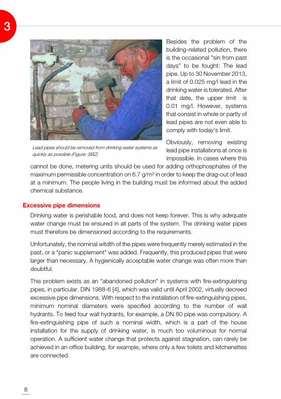
Besides the problem of thebuilding-related pollution, thereis the occasional "sin from pastdays" to be fought: The leadpipe. Up to 30 November 2013,a limit of 0.025 mg/l lead in thedrinking water is tolerated. Afterthat date, the upper limit is0.01 mg/l. However, systemsthat consist in whole or partly oflead pipes are not even able tocomply with today's limit.
Obviously, removing existinglead pipe installations at once isimpossible. In cases where this
cannot be done, metering units should be used for adding orthophosphates of themaximum permissible concentration on 6.7 g/m³ in order to keep the drag-out of leadat a minimum. The people living in the building must be informed about the addedchemical substance.
Excessive pipe dimensions
Drinking water is perishable food, and does not keep forever. This is why adequatewater change must be ensured in all parts of the system. The drinking water pipesmust therefore be dimensioned according to the requirements.
Unfortunately, the nominal witdth of the pipes were frequently merely estimated in thepast, or a "panic supplement" was added. Frequently, this produced pipes that werelarger than necessary. A hygienically acceptable water change was often more thandoubtful.
This problem exists as an "abandoned pollution" in systems with fire-extinguishingpipes, in particular. DIN 1988-6 [4], which was valid until April 2002, virtually decreedexcessive pipe dimensions. With respect to the installation of fire-extinguishing pipes,minimum nominal diameters were specified according to the number of wallhydrants. To feed four wall hydrants, for example, a DN 80 pipe was compulsory. Afire-extinguishing pipe of such a nominal width, which is a part of the houseinstallation for the supply of drinking water, is much too voluminous for normaloperation. A sufficient water change that protects against stagnation, can rarely beachieved in an office building, for example, where only a few toilets and kitchenettesare connected.
Lead pipes should be removed from drinking water systems asquickly as possible (Figure: SBZ)
3
9
A water change according to the oldstandard would be adequate if 1.5times the pipe contents were changedper week at a minimum of 20 per centof the designed volume flow of the wallhydrant. Instead of feeding the entiresanitary installation via the fire-extinguishing pipe, there is frequentlyjust one single kitchenette at the end ofthe pipe. These 4.2 liters per minutethat can be taken out of the system inthe kitchen at the most, are opposed tothe requirement of 300 liters per minuteand more for fire fighting. There surelycan not be any adequate waterchange.
Stagnation in feeder pipes
The new DIN 1988-6 [5], too, can onlyprovide a partial solution of thestagnation problem in fire-extinguishing pipes. The requirementfor minimum nominal diameters for fire-extinguishing pipes no longer exists.And wall hydrants may only beconnected to the drinking-water-carrying pipes when the volumetric flow rate of the connected sanitary equipmentexceeds the volumeric flow rate required for the fire-extinguishing water.
If, however, wall hydrants are employed that shall be used by the fire brigade, thewater flow required here can hardly be achieved via a "normal" water consumption.These hydrants must be fed with 100 liters per minute each. It must also be agreedhow many of the existing wall hydrants are to be used simultaneously. If the requiredfire-extinguishing water volume exceeds the drinking water volume, the fire-extinuishing pipe is no longer allowed to carry drinking water.
This situation quickly takes us to the idea of separating the systems for drinking waterand fire-extinguishing water. However, the assumption of having solved all problemsis not justified. If fire-extinguishing water is not required, there will be no water flow inthe feeder pipe to the indirect connection. The stagnation problem is thus shifted tothe point before that connection.
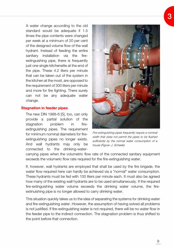
Fire-extinguishing pipes frequently require a nominalwidth that does not permit the pipes to be flushedsufficiently by the normal water consumption of ahouse (Figure: J. Scheele)
3
10
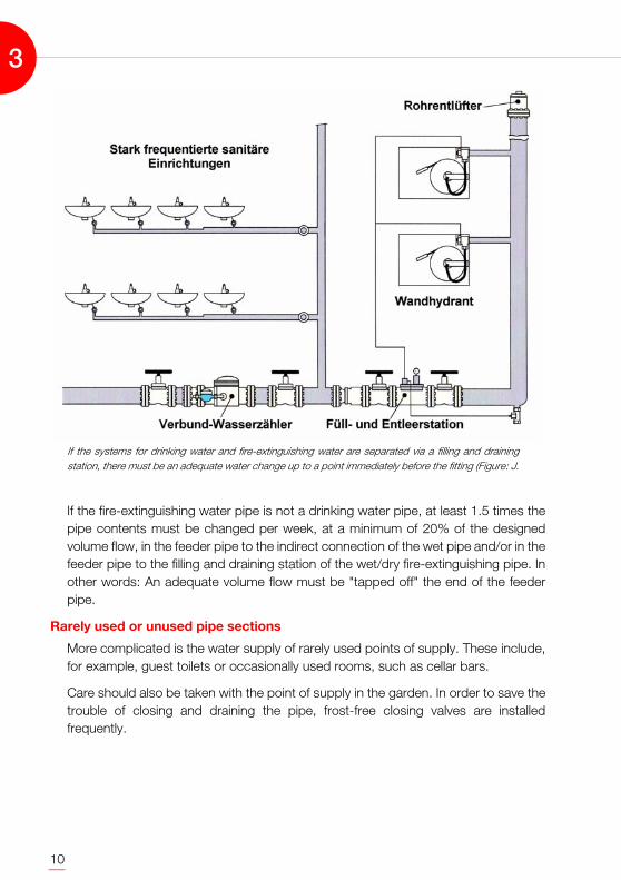
If the fire-extinguishing water pipe is not a drinking water pipe, at least 1.5 times thepipe contents must be changed per week, at a minimum of 20% of the designedvolume flow, in the feeder pipe to the indirect connection of the wet pipe and/or in thefeeder pipe to the filling and draining station of the wet/dry fire-extinguishing pipe. Inother words: An adequate volume flow must be "tapped off" the end of the feederpipe.
Rarely used or unused pipe sections
More complicated is the water supply of rarely used points of supply. These include,for example, guest toilets or occasionally used rooms, such as cellar bars.
Care should also be taken with the point of supply in the garden. In order to save thetrouble of closing and draining the pipe, frost-free closing valves are installedfrequently.
If the systems for drinking water and fire-extinguishing water are separated via a filling and drainingstation, there must be an adequate water change up to a point immediately before the fitting (Figure: J.
3
11
This eliminates the risk of frozen pipes, butnot the risk of stagnation. At low outsidetemperatures, neither the garden iswatered nor the patio swept - the waterremains still in the feeder pipe. Providingsuch connections with feeder and returnpipes helps. One solution could be toroute the water to the kitchen first via theconnection of the frost-free outdoorclosing valve.
This hygienical necessity shows that amere "plugging off" of no longer neededpoints of supply or to "stock" drinkingwater pipes is not permitted. Such pipes,which are in connection with the drinkingwater system offer bacteria ideal livingconditions. Installing reserve pipes forfuture use is possible - as long as such pipes are not yet connected to the drinkingwater system. In most cases this can be done without any problems: The pipes for afuture conversion of the attic may be preinstalled, but end at an accessible point inthe cellar - ready to be connected to the drinking water system by the plumber whenthe moment comes.
Long pipes to safety fittings
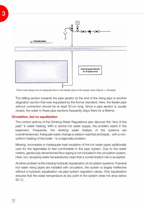
DIN 1988-2 [6] does not limit the length of the feeder pipe to the safety valve of adrinking water heater. The safety valve can be found above the heater or even on adifferent floor. The reason for this recommended installation was the formerassumption that a steady dripping of the safety valve prevents the production ofstagnation water. Today we know that there is actually no stagnation water in thosepipes - but the length of pipe offers bacteria ideal living conditions. The bacteria(legionella, for example) prefer the inside pipe surface at these points. Since thesafety valve merely drips, the flow rate is very low which makes "living" there verycosy. If the valve is to be arranged above the heater, the cold water supply must alsobe from above. Thus there is an adequate flow in the pipe up to a point immediatelybefore the valve.
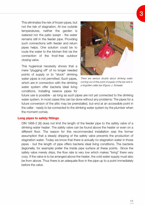
There are serious doubts about drinking watercoming out of this point of supply of the bar sink ina forgotten cellar bar (Figure: J. Scheele)
3
12
The stilling section towards the pipe aerator at the end of the rising pipe is anotherstagnation section that was requested by the former standard. Here, the feeder pipewithout connection should be at least 50 cm long. Since a pipe aerator is usuallyclosed, the water in these pipe sections frequently stays there for a lifetime.
Circulation, but no equalization
The control options of the Drinking Water Regulations also discover the "sins of thepast" in water heating. With a central hot water supply, the problem starts in thebasement. Frequently, the drinking water heaters of the systems areoverdimensioned. Adequate water change is seldom reached and leads - with a non-uniform heating of the boiler - to a legionella problem.
Missing, incomplete or inadequate heat insulation of the hot water pipes additionallycare for the legionellae to feel comfortable in the pipe system. Due to the watermeters, generously dimensioned floor piping is not included in the circulation system.Here, too, dropping water temperatures mean that a contamination risk is accepted.
Another problem is the missing hydraulic equalization of circulation systems: If severalhot water rising pipes are installed with circulation, the system is largely ineffectivewithout a hydraulic equalization via pipe system regulation valves. Only equalizationensures that the water temperature at any point in the system does not drop below55 °C.
There must always be an adequate flow in the feeder pipe to the savety valve (Figure: J. Scheele)
3
13
4. STANDARDS FOR THE PROTECTION OF DRINKING WATER
To avoid a quality loss due to the penetration of non-drinking water, safety fittingsmust be installed at the points of supply at which non-drinking water could bepressed, sucked or flow back. The protective measures are regulated in the currentlyvalid DIN 1988-4 [7]. Since May 2001, DIN EN 1717 [8] is available as a standard thatalso deals with measures for the protection of drinking water.
Replacement only possible in a package
Currently, both standards are valid in parallel. This is due to the fact that the ECmembers must convert approved EN standards into national Technical Rules (inGermany DIN-EN standards). At the same time, DIN 1988 with its eight parts is ablock standard (also known as "package solution"). Only the entire standard can bedeclared invalid, not individual parts of it. Consequently, DIN 1988 can only bedropped when there are corresponding European equivalents for all eight parts.
And there is a good reason for it: The eight parts of DIN 1988 mesh like the gears ofa clockwork. A partial replacement of individual parts of the standard would only beconceivable if a change did not affect this "mechanical system". This is why there arecurrently two standards that deal with the "protection of drinking water". There is onlyone problem - they contradict each other in some parts.
Agree only one standard in a contract for services
Frequently it is said that DIN-EN standards are not a patch on DIN standards. Aprejudice that frequently results in the "European standards" being completelyignored. If, however, you dare looking at the DIN EN 1717 you will see that -compared with DIN 1988-4 - the requirements are higher. If ATV DIN 18381 [9] isused as the basis of a contract for services, both standards should be agreed inparallel. In terms of protection, both definitions cannot be fulfilled equally..
Example:
Situation 1:
For a temporary hose connection, the point of supply for filling the heating toDIN 1988-4 was only equipped with a backflow preventer. The customer complainsthat this installation is unsafe and does not fulfil the safety requirements of the "new"DIN EN 1717.
4
14
Situation 2:
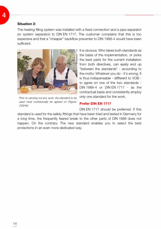
The heating filling system was installed with a fixed connection and a pipe separator(or system separator) to DIN EN 1717. The customer complains that this is tooexpensive and that a "cheaper" backflow preventer to DIN 1988-4 would have beensufficient.
It is obvious: Who takes both standards asthe basis of the implementation, or picksthe best parts for the current installationfrom both directives, can easily end up"between the standards" - acoording tothe motto: Whatever you do - it's wrong. Itis thus indispensable - diffferent to VOB -to agree on one of the two standards -DIN 1988-4 or DIN EN 1717 - as thecontractual basis and consistently employonly one standard for the work.
Prefer DIN EN 1717
DIN EN 1717 should be preferred. If thisstandard is used for the safety fittings that have been tried and tested in Germany fora long time, the frequently feared break to the other parts of DIN 1988 does nothappen. On the contrary: The new standard enables you to select the bestprotections in an even more dedicated way.
Prior to carrying out any work, the standard to beused must contractually be agreed on (Figure:ZVSHK)
4

15
5. THE STANDARDS IN PRACTICE COMPARISON
In practice, people are frequently reluctant to take the step to the application ofDIN EN 1717 [8]. After all, we are quite familiar with the "old" DIN 1988-4 [7] andexpect something completely new from the European standard. This impressionresults from protections that are described in the standard, which are not yetemployed in Germany up to now. However, if you bear in mind that there is nonecessity to employ unusual safety options now, the differences between thestandards are in the details. We want to show these details below.
Collective protections are obsolete
The reason for penetrating non-drinkingwater can be, that the water is pressed orsucked back or flows back. Points ofsupply at which this is possible are knownas vulnerable points of supply. A vulnerablepoint of supply can be, for example, amixing valve for filling the bath tub that isequipped with a shower head. It possessesa shower attachment that can drop into thetub and lie underneath the water surface. Asafety device must prevent the water fromthe tub to be sucked into the showerattachment and thus into the drinking waterpipe.
Points of supply where non-drinking watercannot flow back into the pipe are safepoints of supply. Such points of supply are,for example, wash basin tabs with a fixedoutlet, or the flushing cistern of a toilet. Inboth systems, the water supply is above thelevel of the non-drinking water.
Vulnerable points of supply must beprotected with a safety fitting. There are twodifferent possible implentation variants toDIN 1988-4. Protection is possible as anindividual protection or as a collectiveprotection. In an installation with individualprotection, each vulnerable point of supply is allocated to its safety device. In aninstallation with collective protection, several or even all vulnerable points of supply ofa system are protected by a safety fitting.
Vulnerable points of supply are, for example,points where the drinking water outlet can bebelow the level of the non-drinking water
This point of supply is not vulnerable - as long asit is not misused (by placing a bucket underneath,for example)
5
16
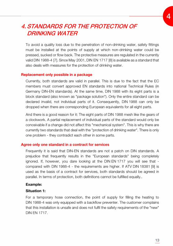
A widely used example of a collective protection is the utilization of a backflowpreventer at the bottom of a rising pipe in conjunction with a pipe aerator at the endof the rising pipe. This tpye of protection has always been a problem since flowing orsucking back within the system in flow direction after the backflow preventer cannever be excluded. This is why the term "drinking water system" already defines thatthis system ends at the free outlet or at the safety fitting. In the case decribed here,the drinking water system thus does not lead up to the points of supply - it ends atthe backflow preventer at the foot of a rising pipe. If, for example, a pipe separator isinstalled immediately after the water meter in order to protect the entire building, thedrinking water system according to the standard ends there. With respect to theDrinking Water Regulations, you quickly have a lot of explaining to do. TheseRegulations request that the drinking water system goes up to the point of supply.
Collective protection is frequently the cause of problems concerning the waterhygiene. Flowless feeders to pipe areators in the hot water system represent an idealbreeding ground for bacteria, such as legionellae. The DVGW workingsheet W 551 [10] therefore requests the removal of pipe aerators when hygieneproblems arise. Items that are to be removed from old systems should logically notbe used at all for new systems.
Even more explicit is DIN EN 1717. It defines that safety devices must always be used
A collective protection is not able to prevent flowing, sucking or pressing back in flow directionafter the safety fitting (Figure: J. Scheele)
5
17
as individual protection devices. The possibility of using a safety fitting in the domesticarea as a collective protection is restricted to exceptions. This requirement is alreadyimplemented in practice: The manufactuers of branded fittings already offer themajority of their outlet fittings with integrated safety devices.
Increased safety standard when selecting safety fittings
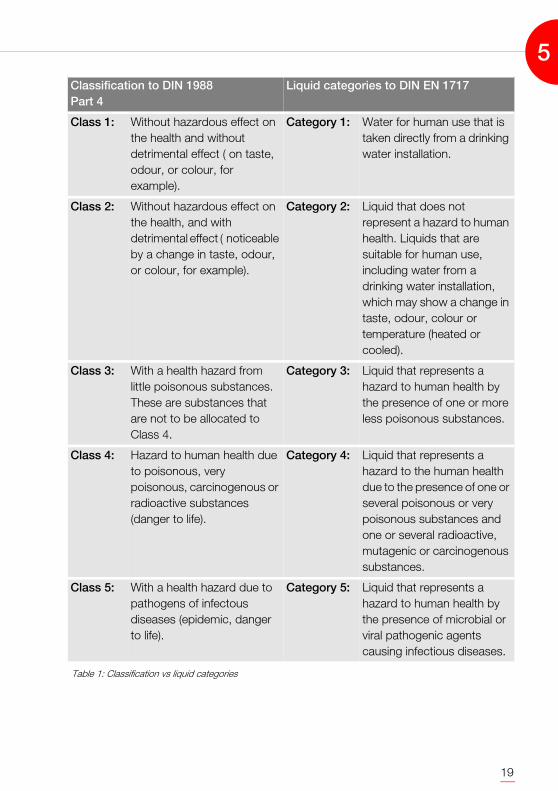
The individual safety fittings feature different safety standards. It is thus possible thata backflow preventer, for example, does not close tightly and is not able to performits task correctly. This is why it is only allowed to be used for protecting non-drinkingwater where a backflow is annoying, but not dangerous. Safety fittings of a very lowfailure probability must be installed if the drinking water is to be protected againsthazardous non-drinking water. DIN 1988-4 specifies five different water classes toassess the non-drinking water that must be separated. Instead, DIN EN 1717describes five different liquid categories. When we compare these definitions, we cansee: Merely the name of the game was changed. The facts remained virtuallyunchanged: (see Table 1, page 19)
DIN EN 1717 merely tightens the liquid categories: The term "detrimental effect"cannot be found here.
DIN 1988-4, in contrast, differentiates class-2 water with respect to "detrimentaleffect" and "hazard". There is a hazard when the health of the water user can beaffected detrimentally. A detrimental effect of the water means that the water haschanged (odour, taste, colour), but does not have any effect on the health of theconsumer. If you look exactly, you can see that a risk cannot be excluded with anydetrimenal effect. It depends on the consumer whether or not a change in the waterhas a detrimental effect or is hazardous. While a glass of beer (class-2 water), forexample, is harmless for an adult, it can be lethal for a baby.
The situation-related selection of the safety fittings is made according to the waterclass and/or liquid category of the non-drinking water against which protection isrequired. The water class is the sole selection criteria in DIN 1988-4.
In DIN EN 1717, there is another weighing factor in addition to the liquid category:The selection of the safety fitting also takes into account whether the non-drinkingwater can flow back, be sucked back or be pressed back. Under this aspect, somesafety devices that may protect against flowing or sucking back up to liquid categoryfive are not suitable if pressing back is to be expected. Example:
A pipe interruptor is a "length of pipe with holes". The negative pressure is reliablyrelieved through the holes if there is a suck-back effect in the drinking water pipe.Sucking in non-drinking water via the pipe interruptor is not possible. If, however, thenon-drinking water is pressurized - due to faulty operation - and presses towards thedrinking water pipe, part of it squirts out of the pipe through the holes of the pipe
5
18
interruptor, but the non-drinking water cannot be prevented from entering thedrinking water pipe.
Compared with DIN 1988-4, the second selection criterion to DIN EN 1717 thusprovides a higher degree of protection. This degree of protection is furtheremphasized by the fact that there is no "temporary connection" in DIN EN 1717. Itcan only be found in DIN 1988-4. Here, safety fittings with a degree of protection canbe used that is lower that the one required for a permanent connection, provided thatthe connection only exists for one working day and is continuously monitored duringthis time. The question is, why poisonous water, for example, is expected to be lesshazardous when it is connected to the drinking water system for a maximum of oneworking day. The consideration of this fact already shows that it is a very good thingthat DIN EN 1717 no longer contains the "temporary connection variant".
Notation system for international comprehensibility
The skilled DIN-1988 user is used to calling the individual safety fittings quasi "by theirnames". He knows backflow preventers, pipe separators, system separators, pipeinterruptors etc. There are no problems with this in a national standard. It is morecomplicated on the international scene. Here, the initial standard (i.e. EN 1717) mustfinally be translated into the language of the respective member state. In this context,we find out that there is no English word for "Systemtrenner" [system separator]. Weemploy a notation system in order to preclude translation-related misunderstandingsin such a situation.
This system allocated the safety devices to groups. Within the group, we differentiateaccording to types. The group and/or the type of the safety device has a letterallocated. The free outlet, for example, is allocated to group A. Depending on theversion of the outlet, we distinguish between the types A - G. If, for example, you wantto name the outlet found in a flushing cistern, you merely specify "safety device AA"and you know unambiguously what is meant. The following allocations are possiblewhen you restrict yourself to the safety equipment that is common in Germany: (seeTable 2, page 20)
5
19
Table 1: Classification vs liquid categories
Classification to DIN 1988 Part 4
Liquid categories to DIN EN 1717
Class 1: Without hazardous effect on the health and without detrimental effect ( on taste, odour, or colour, for example).
Category 1: Water for human use that is taken directly from a drinking water installation.
Class 2: Without hazardous effect on the health, and with detrimental effect ( noticeable by a change in taste, odour, or colour, for example).
Category 2: Liquid that does not represent a hazard to human health. Liquids that are suitable for human use, including water from a drinking water installation, which may show a change in taste, odour, colour or temperature (heated or cooled).
Class 3: With a health hazard from little poisonous substances. These are substances that are not to be allocated to Class 4.
Category 3: Liquid that represents a hazard to human health by the presence of one or more less poisonous substances.
Class 4: Hazard to human health due to poisonous, very poisonous, carcinogenous or radioactive substances (danger to life).
Category 4: Liquid that represents a hazard to the human health due to the presence of one or several poisonous or very poisonous substances and one or several radioactive, mutagenic or carcinogenous substances.
Class 5: With a health hazard due to pathogens of infectous diseases (epidemic, danger to life).
Category 5: Liquid that represents a hazard to human health by the presence of microbial or viral pathogenic agents causing infectious diseases.
5

20
Table 2: Nomenclature of the safety devices to DIN EN1717 and DIN 1988-4
The pipe separator EA3 cannot be found in the Table on the previous page. There isno equivalent to this fitting in DIN EN 1717. Likewise, the pipe aerators for rising pipes
DIN EN 1717 DIN 1988-4
Name Safety device Safety device
AA Unobstructed free outlet Free outlet
AB Free outlet with a non-circular overflow (unrestricted)
Free outlet (only at the manufacturer side in intrinsically safe washing machines and dishwashers)
BA Pipe separator with controllable medium pressure zone
System separator with measurable medium pressure zone1)
1) Not included in DIN 1988-4; installation is
common practice in Germany.
CA Pipe separator with different not measurable pressure zones
System separator with different not measurable pressure zones
DB Pipe interruptor with moveable parts Pipe interruptor A2
DC Pipe interruptor with permanent connection to the atmosphere
Pipe interruptor A1
EA Measurable backflow preventer Backflow preventer
GA Pipe separator, not flow-controlled Pipe separator EA1
GB Pipe separator, flow-controlled Pipe separator EA2
HA Hose connection with backflow preventer
Backflow preventer
HB Pipe aerator for hose connections Pipe aerator style C
HC Automatic changeover element Changeover element and backflow preventer on outlet fittings with hose connection and free outlet
HD Pipe aerator for hose connections, combined with backflow preventer
Safety combination
5
21
are not listed.
Originally, the notation system adopted in DIN EN 1717 comes from France.However, the logic of the system could not be maintained due to the allocation of allsafety fittings that are common in Europe. The allocation of the letter combinationswas thus arbitrary. Don't try to find any background.
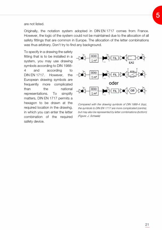
To specify in a drawing the safetyfitting that is to be installed in asystem, you may use drawingsymbols according to DIN 1988-4 and according toDIN EN 1717. However, theEuropean drawing symbols arefrequently more complicatedthan the nationalrepresentations. To simplifymatters, DIN EN 1717 permits ahexagon to be drawn at therequired location in the drawing,in which you can enter the lettercombination of the requiredsafety device.
Compared with the drawing symbols of DIN 1988-4 (top),the symbols to DIN EN 1717 are more complicated (centre),but may also be represented by letter combinations (bottom)(Figure: J. Scheele)
5

22
5

23
6. THE FUNCTION OF THE SAFETY FITTINGS
The safety fittings commonly used in Germany were already mentioned in Chapter 5,and compared with the European names. We now want to explain the functions ofthe individual fittings and - if there are any - describe installation specifications. Thisis done - following the European notation system - from "A" to "H". This does notnecessarily lead to an assessment of the safety of the individual fittings. This safetyaspect is dealt with in Chapter 7.
Unobstructed free outlet - AA (DIN EN 1717)Free outlet (DIN 1988-4)
"Keep your distance" could be the description of the principle of a free outlet. Thename indicates that the drinking water outlet is at some distance to the highestpossible non-drinking water level. To DIN 1988-4 [7], this must invariably be twice theinside diameter of the outlet pipe, but at least 20 mm. DIN EN 1717 [8] requests adistance to the non-drinking water level that must correspond to three times theinside diameter of the outlet pipe. However, it does not specify a minimum distance.Since the drinking water outlet is above the non-drinking water level, the non-drinkingwater can neither flow or press back nor be sucked back in the domestic application.
The catch of using this way of protectionis in the definition of the highest possiblenon-drinking water level. It is frequentlyassumed that this is the overflow of thesanitary object. But an overflow can beobstructed. Even the upper edge of theobject can not always be considered asthe highest possible non-drinking waterlevel. For example, there is frequentlyfoam on a bath tub. An outlet that isinside the foam is everything else but"free". These operating conditions must also be taken into account when thenecessary distance between the outlet and the non-drinking water level isdetermined.
At washstands with a so-called mouth-flushing tab you must also check criticallywhether there is always a free outlet. The outlet of these fittings are usuallysignificantly above the surface of the washstand. But exactly this makes is possibleto put a bucket underneath. The outlet is then inside the bucket. Each system buildermust decide whether or not there shall be a protection against this non-intentionaluse.
When a free outlet is used, the highest possiblenon-drinking water outlet may also be above theupper edge of the container (Figure: A. Gaßner)
6
24
Prior to using a free outlet you mustdetermine whether harmful vapours canget into the outlet. This can be the case incommercial or industrial systems. There islittle use if the water outlet to a basin withpoisonous chemicals uses a free outlet,although the poison find a way as a gasinto the water pipe.
In addition to the described free outlet AA,only version AB (free outlet with non-circular overflow) is used in Germany.However, it is not used in domesticdrinking water installations, but as a safetydevice in intrinsically safet washing
machines and dishwashers.
Pipe separator with controllable medium pressure zone - BA (DIN EN 1717)System separatur with controllable medium pressure zone
The system separator is a safety fitting that is not listed in DIN 1988-4. Still, this fittingestablished itself in Germany in the 1990s. It is somewhat confusing that theEuropean term is "pipe separator". This was born of necessity since there is noEnglish word for "system separator".
A system separator consists of threechambers. Between the chambers thereare backflow preventers. The water firstflows into the prechamber. Here, thewater pressure is higher than in the middlechamber, where in turn it is higher than inthe outlet chamber. The pressure drop thewater experiences when it flows through isdefined exactly. If the water pressurebefore the system separator drops, thusreducing the volume flow and producing arisk of sucking or pressing back, thebackflow preventer between theprechamber and the middle chambercloses. This happens, at the latest, when apressure difference of 0.14 bars isreached. The drain valve in the middle chamber opens at the same time. The middlechamber is thus emptied. This requires a draining connection for this fitting. Thanksto the (technically seen) pressureless middle chamber, the water that is still standing
This should not be: The overflow (right) is higherthan the supposedly free outlet (left)
OverflowOutlet
The drain valve remains closed as long as thepressure in the feeder pipe is 0.14 bars higher thanthe pressure in the middle chamber
6
25
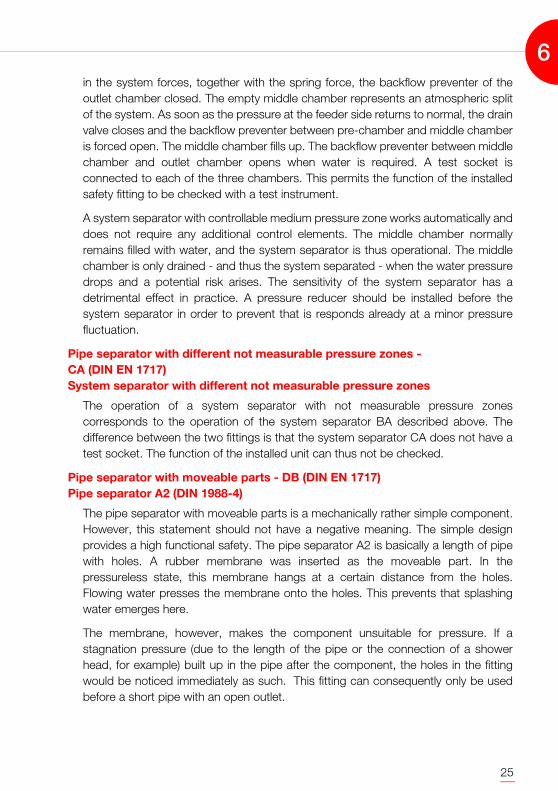
in the system forces, together with the spring force, the backflow preventer of theoutlet chamber closed. The empty middle chamber represents an atmospheric splitof the system. As soon as the pressure at the feeder side returns to normal, the drainvalve closes and the backflow preventer between pre-chamber and middle chamberis forced open. The middle chamber fills up. The backflow preventer between middlechamber and outlet chamber opens when water is required. A test socket isconnected to each of the three chambers. This permits the function of the installedsafety fitting to be checked with a test instrument.
A system separator with controllable medium pressure zone works automatically anddoes not require any additional control elements. The middle chamber normallyremains filled with water, and the system separator is thus operational. The middlechamber is only drained - and thus the system separated - when the water pressuredrops and a potential risk arises. The sensitivity of the system separator has adetrimental effect in practice. A pressure reducer should be installed before thesystem separator in order to prevent that is responds already at a minor pressurefluctuation.
Pipe separator with different not measurable pressure zones - CA (DIN EN 1717) System separator with different not measurable pressure zones
The operation of a system separator with not measurable pressure zonescorresponds to the operation of the system separator BA described above. Thedifference between the two fittings is that the system separator CA does not have atest socket. The function of the installed unit can thus not be checked.
Pipe separator with moveable parts - DB (DIN EN 1717) Pipe separator A2 (DIN 1988-4)
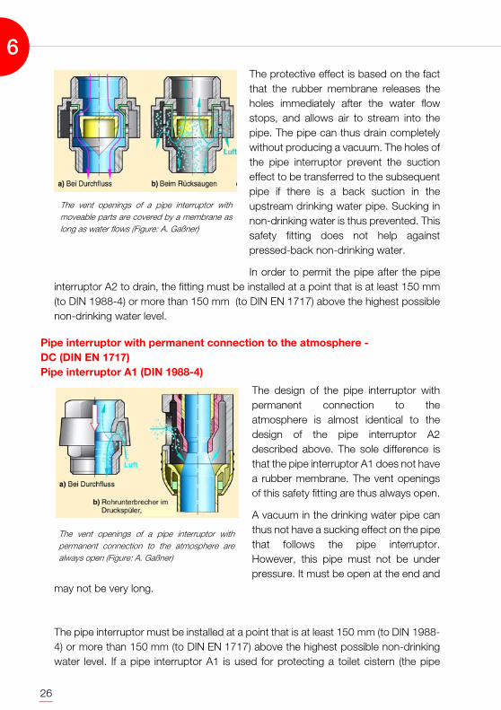
The pipe separator with moveable parts is a mechanically rather simple component.However, this statement should not have a negative meaning. The simple designprovides a high functional safety. The pipe separator A2 is basically a length of pipewith holes. A rubber membrane was inserted as the moveable part. In thepressureless state, this membrane hangs at a certain distance from the holes.Flowing water presses the membrane onto the holes. This prevents that splashingwater emerges here.
The membrane, however, makes the component unsuitable for pressure. If astagnation pressure (due to the length of the pipe or the connection of a showerhead, for example) built up in the pipe after the component, the holes in the fittingwould be noticed immediately as such. This fitting can consequently only be usedbefore a short pipe with an open outlet.
6
26
The protective effect is based on the factthat the rubber membrane releases theholes immediately after the water flowstops, and allows air to stream into thepipe. The pipe can thus drain completelywithout producing a vacuum. The holes ofthe pipe interruptor prevent the suctioneffect to be transferred to the subsequentpipe if there is a back suction in theupstream drinking water pipe. Sucking innon-drinking water is thus prevented. Thissafety fitting does not help againstpressed-back non-drinking water.
In order to permit the pipe after the pipeinterruptor A2 to drain, the fitting must be installed at a point that is at least 150 mm(to DIN 1988-4) or more than 150 mm (to DIN EN 1717) above the highest possiblenon-drinking water level.
Pipe interruptor with permanent connection to the atmosphere - DC (DIN EN 1717) Pipe interruptor A1 (DIN 1988-4)
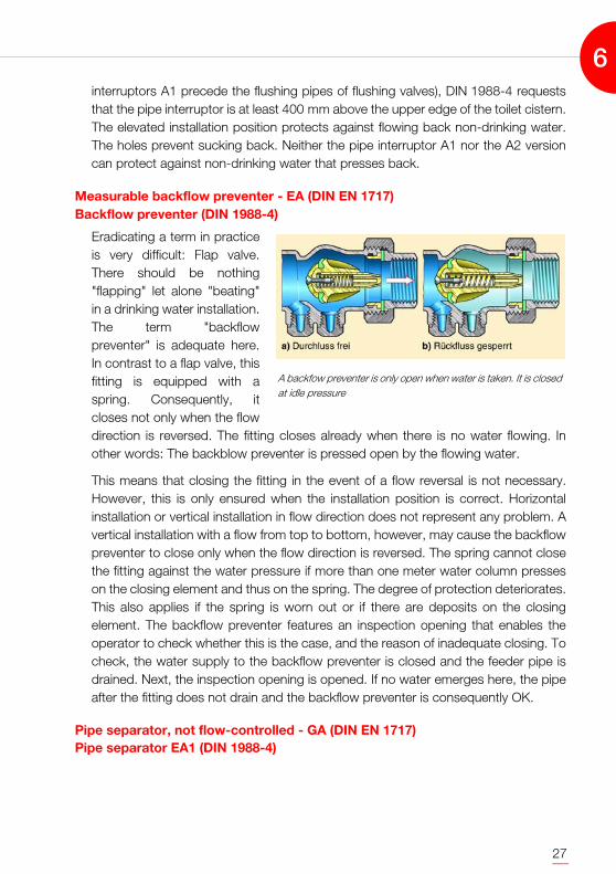
The design of the pipe interruptor withpermanent connection to theatmosphere is almost identical to thedesign of the pipe interruptor A2described above. The sole difference isthat the pipe interruptor A1 does not havea rubber membrane. The vent openingsof this safety fitting are thus always open.
A vacuum in the drinking water pipe canthus not have a sucking effect on the pipethat follows the pipe interruptor.However, this pipe must not be underpressure. It must be open at the end and
may not be very long.
The pipe interruptor must be installed at a point that is at least 150 mm (to DIN 1988-4) or more than 150 mm (to DIN EN 1717) above the highest possible non-drinkingwater level. If a pipe interruptor A1 is used for protecting a toilet cistern (the pipe
The vent openings of a pipe interruptor withmoveable parts are covered by a membrane aslong as water flows (Figure: A. Gaßner)
The vent openings of a pipe interruptor withpermanent connection to the atmosphere arealways open (Figure: A. Gaßner)
6
27
interruptors A1 precede the flushing pipes of flushing valves), DIN 1988-4 requeststhat the pipe interruptor is at least 400 mm above the upper edge of the toilet cistern.The elevated installation position protects against flowing back non-drinking water.The holes prevent sucking back. Neither the pipe interruptor A1 nor the A2 versioncan protect against non-drinking water that presses back.
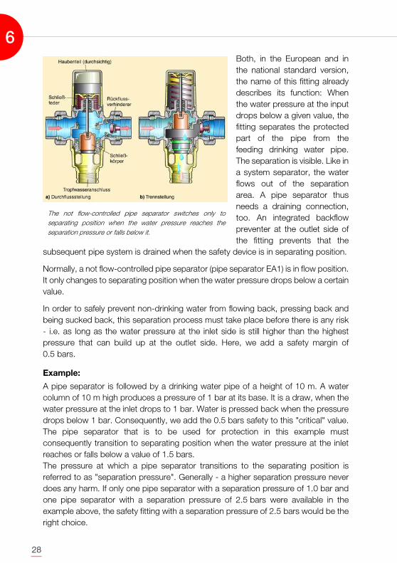
Measurable backflow preventer - EA (DIN EN 1717)Backflow preventer (DIN 1988-4)
Eradicating a term in practiceis very difficult: Flap valve.There should be nothing"flapping" let alone "beating"in a drinking water installation.The term "backflowpreventer" is adequate here.In contrast to a flap valve, thisfitting is equipped with aspring. Consequently, itcloses not only when the flowdirection is reversed. The fitting closes already when there is no water flowing. Inother words: The backblow preventer is pressed open by the flowing water.
This means that closing the fitting in the event of a flow reversal is not necessary.However, this is only ensured when the installation position is correct. Horizontalinstallation or vertical installation in flow direction does not represent any problem. Avertical installation with a flow from top to bottom, however, may cause the backflowpreventer to close only when the flow direction is reversed. The spring cannot closethe fitting against the water pressure if more than one meter water column presseson the closing element and thus on the spring. The degree of protection deteriorates.This also applies if the spring is worn out or if there are deposits on the closingelement. The backflow preventer features an inspection opening that enables theoperator to check whether this is the case, and the reason of inadequate closing. Tocheck, the water supply to the backflow preventer is closed and the feeder pipe isdrained. Next, the inspection opening is opened. If no water emerges here, the pipeafter the fitting does not drain and the backflow preventer is consequently OK.
Pipe separator, not flow-controlled - GA (DIN EN 1717)Pipe separator EA1 (DIN 1988-4)
A backfow preventer is only open when water is taken. It is closedat idle pressure
6
28
Both, in the European and inthe national standard version,the name of this fitting alreadydescribes its function: Whenthe water pressure at the inputdrops below a given value, thefitting separates the protectedpart of the pipe from thefeeding drinking water pipe.The separation is visible. Like ina system separator, the waterflows out of the separationarea. A pipe separator thusneeds a draining connection,too. An integrated backflowpreventer at the outlet side ofthe fitting prevents that the
subsequent pipe system is drained when the safety device is in separating position.
Normally, a not flow-controlled pipe separator (pipe separator EA1) is in flow position.It only changes to separating position when the water pressure drops below a certainvalue.
In order to safely prevent non-drinking water from flowing back, pressing back andbeing sucked back, this separation process must take place before there is any risk- i.e. as long as the water pressure at the inlet side is still higher than the highestpressure that can build up at the outlet side. Here, we add a safety margin of0.5 bars.
Example:
A pipe separator is followed by a drinking water pipe of a height of 10 m. A watercolumn of 10 m high produces a pressure of 1 bar at its base. It is a draw, when thewater pressure at the inlet drops to 1 bar. Water is pressed back when the pressuredrops below 1 bar. Consequently, we add the 0.5 bars safety to this "critical" value.The pipe separator that is to be used for protection in this example mustconsequently transition to separating position when the water pressure at the inletreaches or falls below a value of 1.5 bars. The pressure at which a pipe separator transitions to the separating position isreferred to as "separation pressure". Generally - a higher separation pressure neverdoes any harm. If only one pipe separator with a separation pressure of 1.0 bar andone pipe separator with a separation pressure of 2.5 bars were available in theexample above, the safety fitting with a separation pressure of 2.5 bars would be theright choice.
The not flow-controlled pipe separator switches only toseparating position when the water pressure reaches theseparation pressure or falls below it.
6

29
The separation pressure is determined by the tension of a spring. The springpermanently "tries" to pull the closing element into the seat and thus in separatingposition. This is prevented by the water pressure that acts against the spring force. Ifthe applied water pressure drops to or below the value of the separating pressure,the spring can pull the closing element upwards and thus in separating position.When the water pressure rises, it presses the closing element back down. The flowposition is attained. This is called a „force comparison principle“.
The disadvantage of a pipe separator EA1 is the fact that they are only in separatingposition when the water pressure at the inlet is low. Since this occurs very rarely, thefitting is in flow position for most of the time. If the yearly inspection is dropped (whichis frequently the case in practice), the unit may not be able to switch to separatingposition when it comes to it. It is stuck - due to deposits, calcification, etc..
Pipe separator, flow-controlled - GA (DIN EN 1717)Pipe separator EA2 (DIN 1988-4)
The flow-controlled pipeseparators basicallywork in the same way asthe not flow-controlledversions: They change toseparating positionwhen the inlet waterpressure reaches or fallsbelow the determinedseparation pressure. Theprocedure ofdetermining theseparation pressure isthe same as the one forthe EA1 pipe separators.The major difference is inthe fact that the EA2pipe separator does not only transition to the separating position when the waterpressure reaches critical values. It separates also when no water is taken from thepipe system after the fitting. This fitting is thus always in separating position - with theexception of the moments when water is taken from the system.
Flow-related control is achieved by sensing the water pressure at the outlet. A back-pressure chamber is emptied when the water pressure at the outlet is identical withthe water pressure at the inlet (which is the case if no water is taken). The spring canthus move the closing element of the pipe separator to the separating position. Whenthe water pressure at the outlet side drops (i.e. when water is taken), the back-
The flow-controlled pipe separator is only in flow position when water istaken from the downstream pipe
6

30
pressure chamber is filled with water and the closing element is thus pressed backto the flow position. If the total water pressure is low (less than or equal to theseparation pressure), even a full back-pressure chamber cannot prevent the springfrom pulling the closing element up (and thus in separating position). With criticalpressure conditions, taking water is thus interrupted or not possible. Like in the notflow-controlled pipe separator, a backflow preventer prevents the downstream pipefrom running empty.
In Germany, however, flow-controlled pipe separators are used that do not feature abackflow preventer at their outlet side. With these so-called EA3 pipe separators, thedownstream pipe is emptied deliberately after each separation process of the fitting.In order to make this happen, an EA3 pipe separator must be at least 300 mm abovethe highest non-drinking water level possible.
Hose connection with backflow preventer - HA (DIN EN 1717)Backflow preventer (DIN 1988-4)
We already discussed the backflow preventer in this Chapter. This was a measurablebackflow preventer. There is no measuring possibility in a backflow preventer withhose connection. This backflow preventer is installed in an outlet fitting. Its functioncorresponds to the function of a measurable backflow preventer - but it does nothave the inspection opening. This fitting should - according to the definitions ofDIN EN 1717 - be installed at more than 200 mm above the highest non-drinkingwater level possible.
Pipe aerator for hose connections - HB (DIN EN 1717)Pipe aerator of style C (DIN 1988-4)
The reason may be in the translation of the EN 1717 from French - but the name "pipeaerator for hose connections" is a contradiction in terms. This aearator do not aeratethe feeding pipe, but the hose wich is connected to that pipe. Consequently, thename "hose aerator" would be more appropriate. In favour of the makers of theEN 1717 we should see that the term "pipe aerator of style C" can also be found inour national standard. When we take DIN EN 1717 as a basis, we can adaptourselves in Germany to the term "hose aerator". The pipe aerators proper that havepreviously been installed at the end of a rising pipe, can no longer be found inDIN EN 1717. Although there are still pipe arators (group L) according to thisstandard, they cannot be compared with the aerators used in Germany.
Thus, DIN EN 1717 for Germany merely leaves the aerator that vents a hose.Basically, the events in the downstream hose are the same as the ones in a pipe thatfollows a pipe interruptor in flow direction: The connected hose is vented and drainedwhen the water supply is interrupted. For this, the vent openings of the fitting must
6
31
be at least 150 mm (to DIN 1988-4) or more than 250 mm (to DIN EN 1717) abovethe highest non-drinking water level possible. The difference between a pipeinterruptor and a hose aerator is in the fact that the hose connected to a hose aeratormay be pressurized. A gate actuator is a part of the hose aerator. It closes theconnection to the air openings as soon as a little pressure builds up. If a suction buildsup in the supplying water pipe (when the pipe is drained, for example), the gateactuator lifts off and allows air to flow in through the aerator. A dangerous vacuumin the connected hose is thus relieved - there can be no sucking-back effect. The airroute is blocked, too, if the non-drinking water is - against its intended flow direction- pressed into the hose and the water pipe does not "suck in" the non-drinking water.The aerator remains without an effect. According to the definitions of DIN EN 1717,the hose aerator is thus no protection against backpressing water.
Automatic changeover element - HC (DIN EN 1717)Changeover element and backflow preventer on outlet fittings (DIN 1988-4)
An automatic changeover element is installed at outlet fittings with hose connection- frequently with tub filling and shower head fittings. This element is used for changingthe water flow manually from the free tub inlet to the hose of the shower head. If thewater pressure drops below 0.5 bars while the shower head is being used, thechangeover element switches the water route back to the free tub inlet. In the eventof a failure of the water supply, water could not be sucked via the shower head hoseinto the pipe, because the tub inlet is open and allows air to come in, thuscompensating for any dangerous vacuum right from the beginning. However, thewater inlet must be more than 250 mm above the highest possible non-drinkingwater level. The backflow preventer at the cold and warm water connections of thefitting contribute to preventing a backflow of the water.
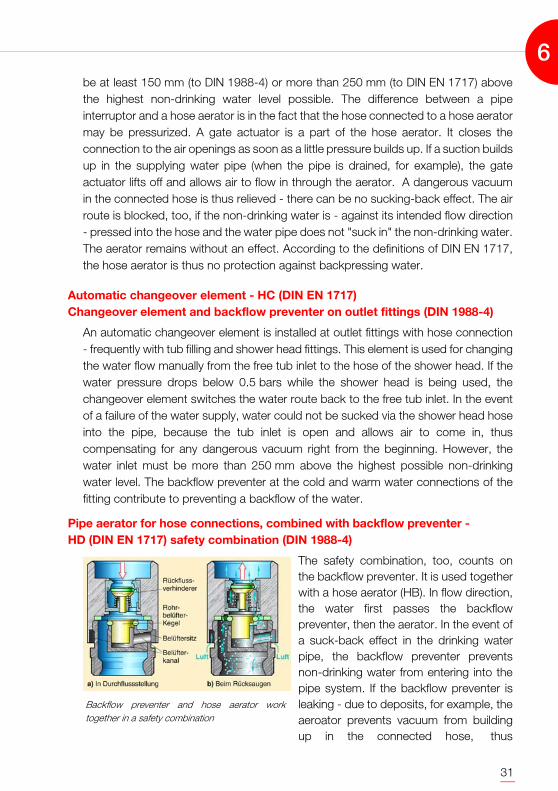
Pipe aerator for hose connections, combined with backflow preventer - HD (DIN EN 1717) safety combination (DIN 1988-4)
The safety combination, too, counts onthe backflow preventer. It is used togetherwith a hose aerator (HB). In flow direction,the water first passes the backflowpreventer, then the aerator. In the event ofa suck-back effect in the drinking waterpipe, the backflow preventer preventsnon-drinking water from entering into thepipe system. If the backflow preventer isleaking - due to deposits, for example, theaeroator prevents vacuum from buildingup in the connected hose, thus
Backflow preventer and hose aerator worktogether in a safety combination
6

32
preventing water to be sucked back. This requires the vent openings of the fitting tobe at least 150 mm (to DIN 1988-4) or more than 250 mm (to DIN EN 1717) abovethe highest possible non-drinking water level. The hose aerator cannot prevent non-drinking water from pressing back. This can only be done by the backflow preventer.As mentioned above, the backflow preventer may be leaking. The degree ofprotection of the safety combination is thus lower when protection againstbackpressing water is required.
Pipe aerators of styles D and E (DIN 1988-4)
As mentioned above in Chapter 5, DIN EN 1717 does not list the pipe aerators thathave been used in Germany up to now. DIN EN 1717 requires the utilization of safetyfittings as individual protection devices; pipe aerators however are usually employedas collective protection devices. It is thus comprehensible, that the pipe aeratorsdropped out of the running in European applications. However, this does not meanthat they disappeared. They are quite numerous in existing building installations.DIN 1988-4 also permits their utilization - although newer national Technical Rules donot support it. This is why the functional description of this safety fitting should not beomitted here.
Due to its shape, a pipe aerator of style D is also known as mushroom aerator. Insidethe aerator there is a float. When the pipe is used, the water presses the float into itsseat. When the rise pipe is drained, the float drops off the seat and air flows into thepipe. This prevents a vacuum and thus a suction effect. The aerator of style D doesnot have a dripping water drainage. Water squirts out if the float does not close properly. They should therefore be usedonly at places where this emerging water cannot do any harm (such as in a closedshower cubicle).
6

33
The pipe aerators of style E work like pipeareators of style D, but are equipped witha dripping water drainage. Since thefunnel of the pipe aerator is hardly able todrain the emerging water completely whenthe float is not tight, many pipe aerators ofstyle E are equipped with a dripping waterlimiter. This is a porous ball that is pressedagainst the outlet by the water pressure. Itcloses the cross section of the outlet andlets only small water quantities emergethrough its pores. In the event of venting,the vacuum pulls it off the outlet into alarger fitting area. Here it is too small to fillthe cross section and allows air to enterthe pipe freely.
The floor pipes must branch off at a heightof 300 mm above the highest possiblenon-drinking water level, and the floor pipemust also be installed at that height when a pipe aerator of style D or E is used. Whena rising pipe with a pipe aerator is offset, a second pipe aerator must be installedbelow the offset if the rectangular offset is greater than 0.5 m. An offset of less than45° requires a second aerator when the projection exceeds 1 m.
In a pipe aerator of style E, a float provides for theclosing. Water presses the float into the seat - aporous ball limits the emerging water volume in theevent of a failure
6
34
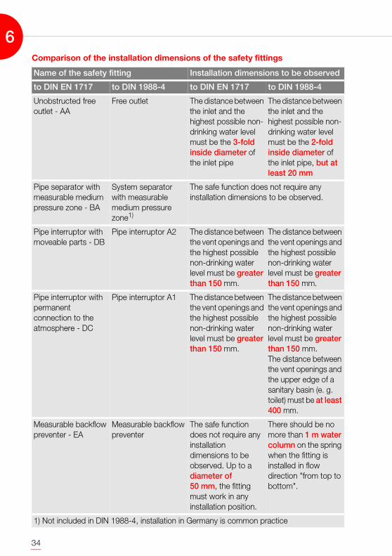
Comparison of the installation dimensions of the safety fittings
Name of the safety fitting Installation dimensions to be observed
to DIN EN 1717 to DIN 1988-4 to DIN EN 1717 to DIN 1988-4
Unobstructed free outlet - AA
Free outlet The distance between the inlet and the highest possible non-drinking water level must be the 3-fold inside diameter of the inlet pipe
The distance between the inlet and the highest possible non-drinking water level must be the 2-fold inside diameter of the inlet pipe, but at least 20 mm
Pipe separator with measurable medium pressure zone - BA
System separator with measurable medium pressure zone1)
The safe function does not require any installation dimensions to be observed.
Pipe interruptor with moveable parts - DB
Pipe interruptor A2 The distance between the vent openings and the highest possible non-drinking water level must be greater than 150 mm.
The distance between the vent openings and the highest possible non-drinking water level must be greater than 150 mm.
Pipe interruptor with permanent connection to the atmosphere - DC
Pipe interruptor A1 The distance between the vent openings and the highest possible non-drinking water level must be greater than 150 mm.
The distance between the vent openings and the highest possible non-drinking water level must be greater than 150 mm.The distance between the vent openings and the upper edge of a sanitary basin (e. g. toilet) must be at least 400 mm.
Measurable backflow preventer - EA
Measurable backflow preventer
The safe function does not require any installation dimensions to be observed. Up to a diameter of 50 mm, the fitting must work in any installation position.
There should be no more than 1 m water column on the spring when the fitting is installed in flow direction "from top to bottom".
1) Not included in DIN 1988-4, installation in Germany is common practice
6
35
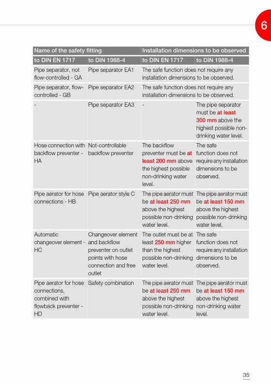
Pipe separator, not flow-controlled - GA
Pipe separator EA1 The safe function does not require any installation dimensions to be observed.
Pipe separator, flow-controlled - GB
Pipe separator EA2 The safe function does not require any installation dimensions to be observed.
- Pipe separator EA3 - The pipe separator must be at least 300 mm above the highest possible non-drinking water level.
Hose connection with backflow preventer - HA
Not-controllable backflow preventer
The backflow preventer must be at least 200 mm above the highest possible non-drinking water level.
The safe function does not require any installation dimensions to be observed.
Pipe aerator for hose connections - HB
Pipe aerator style C The pipe aerator must be at least 250 mm above the highest possible non-drinking water level.
The pipe aerator must be at least 150 mm above the highest possible non-drinking water level.
Automatic changeover element - HC
Changeover element and backflow preventer on outlet points with hose connection and free outlet
The outlet must be at least 250 mm higher than the highest possible non-drinking water level.
The safe function does not require any installation dimensions to be observed.
Pipe aerator for hose connections, combined with flowback preventer - HD
Safety combination The pipe aerator must be at least 250 mm above the highest possible non-drinking water level.
The pipe aerator must be at least 150 mm above the highest non-drinking water level.
Name of the safety fitting Installation dimensions to be observed
to DIN EN 1717 to DIN 1988-4 to DIN EN 1717 to DIN 1988-4
6

36
6
37
7. EMPLOYING SAFETY FITTINGS
The reliability of functioning of the individual safety fittings and protective measuresshould be judged differently. As mentioned above in Chapter 5, the selection of thesuitable protective measure depends on the class (or liquid category) of the non-drinking water the drinking water must be protected from. If the drinking water shallbe shielded against a relatively harmless non-drinking water (e. g. coffee from acoffee machine), using safety fittings with a high failure probability is permitted. Ifwater penetrates the drinking water pipe, the requirements of the Drinking WaterRegulations [2] will no longer be satisfied, but taking water with addedd coffee fromthe pipe is disagreeable at most.
It is completely different when the treatment chairs of a dentist are to be connectedto the water supply of a house. In this case we must assume that germs can beinvolved. This water of class (or liquid category) 5 must never find its way back to thedrinking water pipe system. Consequently, a protection of a very low failureprobability is required.
Degree of protection depends on the non-drinking water
To select the protection that is sufficient for the water supply you must thereforespecify the potential hazard of the non-drinking water against which the drinkingwater is to be protected. Unfortunately, this assessment was not frequently made inthe past. When looking at old systems, we often get the impression that a backflowpreventer or a pipe aerator was understood as a kind of panacea. The battle cry ofthe fitting industry that the outlet fitting is "intrinsically safe" gives you the feeling toprovide sufficient protection in any conceivable case. However, this is not the case.Below, we want to examine more closely the protective aspect of those water outletsituations, water supply companies, planners and fitters are confronted with inpractice.
Temporary points of supply
The necessity of a protection is not necessarily restricted to the area of the customersystem. Water may as well be taken before a customer system. This is the case, forexample, when it is needed at a construction site. Using a standpipe makes itpossible. But where does the pipe lead that is connected to the standpipe?Frequently, it ends in the water trough of the bricklayer. The question about thewhereabouts of the hose end is not only relevant in this water supply situation. It isalways relevant when a standpipe is used.
When the snack stand on a fair is supplied with water, the outlet fittings connected inthis stand require a protection. Checking the existence of an adequate protection isvery difficult for the water supply company.
7
38
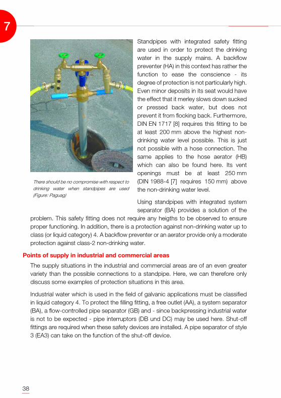
Standpipes with integrated safety fittingare used in order to protect the drinkingwater in the supply mains. A backflowpreventer (HA) in this context has rather thefunction to ease the conscience - itsdegree of protection is not particularly high.Even minor deposits in its seat would havethe effect that it merley slows down suckedor pressed back water, but does notprevent it from flocking back. Furthermore,DIN EN 1717 [8] requires this fitting to beat least 200 mm above the highest non-drinking water level possible. This is justnot possible with a hose connection. Thesame applies to the hose aerator (HB)which can also be found here. Its ventopenings must be at least 250 mm(DIN 1988-4 [7] requires 150 mm) abovethe non-drinking water level.
Using standpipes with integrated systemseparator (BA) provides a solution of the
problem. This safety fitting does not require any heigths to be observed to ensureproper functioning. In addition, there is a protection against non-drinking water up toclass (or liquid category) 4. A backflow preventer or an aerator provide only a moderateprotection against class-2 non-drinking water.
Points of supply in industrial and commercial areas
The supply situations in the industrial and commercial areas are of an even greatervariety than the possible connections to a standpipe. Here, we can therefore onlydiscuss some examples of protection situations in this area.
Industrial water which is used in the field of galvanic applications must be classifiedin liquid category 4. To protect the filling fitting, a free outlet (AA), a system separator(BA), a flow-controlled pipe separator (GB) and - since backpressing industrial wateris not to be expected - pipe interruptors (DB und DC) may be used here. Shut-offfittings are required when these safety devices are installed. A pipe separator of style3 (EA3) can take on the function of the shut-off device.
There should be no compromise with respect todrinking water when standpipes are used(Figure: Paguag)
7
39
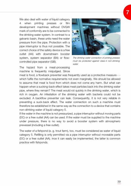
We also deal with water of liquid category4 when printing presses or filmdevelopment machines without DVGWmark of conformity are to be connected tothe drinking water system. In contrast to agalvanic basin, these units need the waterpressure from the pipe. Protection with apipe interruptor is thus not possible. Thecorrect choice of the safety device is a freeoutlet (AA) with downstream boostersystem, system separator (BA) or flow-controlled pipe separator (GB).
The hazard from a meat-processingmachine is frequently misjudged. Sincemeat is food, a flowback preventer was frequently used as a protective measure - -which fulfils the normative requirements not even marginally. We should be allowedto assume that meat is food from which does not come any harm. But what canhappen when a sucking-back effect takes meat particles back into the drinking waterpipe, where they remain? The meat would rot quickly in the drinking water, which isrich in oxygen. An infestation of the drinking water with bacteria could not beexcluded. A backflow preventer can leak. Consequently, it is not very reliable inpreventing a suck-back effect. The water connection on such a machine musttherefore be established in the same way as the connection to a device that containsnon-drinking water of liquid category 5. If the water in the machine is not pressurized, a pipe interruptor without moving parts(DC) or a free outlet (AA) can be used. If the water must be supplied to the machineunder pressure, there is no way to avoid a booster system with atmosphericprevessel (including a free outlet).
The water of a fishpond (e. g. trout farm), too, must be considered as water of liquidcategory 5. Refilling is only permitted via a pipe interruptor without moveable parts(DC) or a free outlet (AA). ince it can easily be implemented, the latter is commonpractice with fishponds.
The drinking water connection of printing pressesmust be protected against class-4 non-drinkingwater
7
40
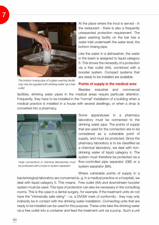
At the place where the trout is served - inthe restaurant - there is also a frequentlyunexpected protection requirement. Theglass washing facility on the bar has awater inlet underneath the water level, thebottom rinsing pipe.
Like the water in a dishwasher, the waterin the basin is assigned to liquid category5. This shows the necessity of a protectionvia a free outlet (AA), combined with abooster system. Compact systems thatare ready to be installed are available.
Points of supply in the medical area
Besides industrial and commercialfacilities, drinking water pipes in the medical areas require particular attention.Frequently, they have to be installed in the "normal" installation of a building when amedical practice is installed in a house with several dwellings, or when a shop isconverted into a pharmacy.
Some apparatuses in a pharmacylaboratory must be connected to thedrinking water pipe. The points of supplythat are used for the connection are to beconsidered as a vulnerable point ofsupply, and must be protected. Since thepharmacy laboratory is to be classified asa chemical laboratory, we deal with non-drinking water of liquid category 4. Thesystem must therefore be protected via aflow-controlled pipe separator (GB) or asystem separator (BA).
Where vulnerable points of supply in abacteriological laboratory are concerned (e. g. in a medical practice or a hospital), wedeal with liquid category 5. This means: Free outlet (AA) and downstream boostersystem must be used. This type of protection can also be necessary in the consultingrooms. This is the case in a dental surgery, for example. If the treatment units do nothave the "intrinsically safe rating" - i.e. a DVGW mark of conformity - they may onlyindirectly be in contact with the drinking water installation. Connecting units that areready to be installed can be used for this purpose. These units take the drinking watervia a free outlet into a container and feed the treatment unit via a pump. Such a unit
The bottom rinsing pipe of a glass washing facilitymay only be supplied with drinking water via a freeoutlet
Hose connections in chemical laboratories mustbe protected with a hose or system separator
7

41
can be installed directly next to the chair or in a separate equipment room of thesurgery.
The water pipe installed after that safetyunit (which may only feed one or moretreatment chairs, but no further pointsof supply) must be as small as possible,and short. The treatment chairs needonly very little water (drill coolingrequires approximately 75 ml/min, eachchair needs per treatment dayapproximately 15 liters). Withunnecessary large or long feeder pipeswe have again the problem ofstagnation.
Care must also be taken at bath tubsand shower trays in hospitals or nursinghomes. The supply fittings that areinstalled here are not "intrinsically safe",even if the manufacturer states exactlythis property in his documents. Intrinsically safe fittings can protect against non-drinking water up to liquid category 3. Since we must assume that there are ill peoplewho take a shower or bath in a hospital or a nursing home, the non-drinking watermust here be assigned to liquid category 5. Consequently, the degree of protectionof the "intrinsically safe" fitting proves insufficient. Connecting the shower head (whichmay as well lie in the tub) via a pipe interruptor with movable parts (DB) wouldtherefore be necessary. However, the fitting does not make any sense here, since thedownstream hose is - through the shower head - under flow pressure. As a result,the water would squirt out of the pipe interruptor, rather than out of the shower. Sincethere are currently no intrinsically safe "hospital fittings", there is only one possibility:The inlets and hose connections must be arranged such that they cannot get underthe non-drinking water level. A hose connecting angle installed at a high level and anapproriately short hose do not allow the shower head to land in the tub or showertray.
Points of supply in the domestic area
There are also different protection requirements for the points of supply in aresidential building. Below we look at the facilities that are usual in a residentialbuilding.
The fittings on washstands do not usually represent vulnerable points of supply. Theoutlet of the supply fitting is fixed above the highest possible non-drinking water level,
Dental treatment chairs must be intrinsically safe orbe supplied with water via a separate booster system
7
42
thus fulfilling the requirements for a free outlet (AA). If this is not the case - like with awashstand fitting with extractable shower head - it cannot be excluded that theshower head dives into the non-drinking water. In the domestic area, this non-drinking water can be assigned to liquid category 3. Using a safety combination (HD)is the minimum protection in this case. The same applies to a kitchen fitting withextractable hose shower head.
The water in a toilet cistern corresponds to liquid category 5. Where flushing valvesare used, protection is achieved by a pipe interruptor without moveable parts (DC).Since this pipe interruptor is integrated in the flushing valve, additional safetyequipment need not be installed. If the toilet is flushed through a flushing box, thewater supply is provided as a filling valve with free outlet (AA).
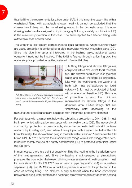
Tub filling fittings and shower fittings areequipped with a free outlet to fill the bathtub. The shower head could lie in the bathwater and must therefore be protected.Like with the washstand, the water of abath tub must be assigned to liquidcategory 3. It must be protected at leastwith a safety combination (HD). This typeof protection is also the minimumrequirement for shower fittings in thedomestic area. Outlet fittings that are"intrinsically safe" according to the
manufacturer specifications are equipped with integrated protective elements.
For bath tubs with a water inlet below the tub brim, a protection to DIN 1988-4 mustbe implemented with a pipe interruptor with moveable parts (DB). The necessity ofsuch a high protection is questionable, since the domestic bath tub still containswater of liquid category 3, even when it is equipped with a water inlet below the tubbrim. Basically, the shower head lying in the bath water is also an "inlet below the tubbrim". DIN EN 1717 confirms the suspicion that things were a little exaggerated here.It requires merely the use of a safety combination (HD) to protect a water inlet underthe tub brim.
In most cases, there is a point of supply for filling the heating in the installation roomof the heat generating unit. Since the heating is not operated at atmosphericpressure, the connection betweeen drinking water system and heating system mustbe established to DIN EN 1717 via at least a pipe separator (GA) or a systemseparator (CA). To DIN 1988-4, a backflow preventer would do for protection in thecase of heating filling. This element is only sufficient when the hose connectionbetween drinking water system and heating is removed immediately after the heating
Tub filling fittings and shower fittings are equippedwith a free outlet to fill the bath tub. The showerhead could lie in the bath water (Figure: Villeroy undBoch)
7

43
has been filled. From practical use we know that the user never removes the hoseafter filling. This is why a safety combination (HD) is installed. According to DIN 1988-4, apermanent connection between drinking water system and heating system ispermitted when a safety combination is employed. But: The highest possible non-drinking water level (i.e. the heating water level) must be at least 150 mm (toDIN EN 1717 even 250 mm) below the openings of the aerator of the safetycombination. This installation requirement is not fulfilled when the safety combinationis installed in the basement.
Points of supply with safety combination(HD) are frequently used to connectwashing machines or dishwashers.Looking at the machine connection, theprotection is either insufficient orexaggerated. When selecting theprotection it is assumed that the machinecan contain water that must be assignedto liquid category 5. This requires a pipeinterruptor without moveable parts (DC) orthe water supply via a free outlet (AA).
Machines with the DVGW mark ofconformity are intrinsically safe. Anadditional safety fitting is not necessary.However, protecting a machineconnection with a safety combinationcannot do any harm. This permits a hose to be connected for other purposes.
European washing machine connection? Washingmachines or dishwashers that are not intrinsicallysafe must actually be connected via a free outlet(Figure: J. Scheele)
7

44
A safety combination (HD) providessufficient protection for the point ofsupply in the garden, too. However, thisapplies exclusively to the connection ofpressureless devices. Connecting ahigh-pressure cleaner without its ownwater tank, for example, to this fitting isnot permitted. A high-pressure cleanerpermits cleaning agents to be mixed inthe water, using the venturi principle.The machine thus works with water ofliquid category 4. The high-pressurecleaner must therefore be connected tothe drinking water pipe via a flow-controlled pipe separator (GB). Thehouse owner (who most likely is inpossession of a high-pressure cleaner)must thus be notified that a high-pressure cleaner must not beconnected to the "outdoor water plug".This is also mentioned in the OperatingInstructions of the high-pressurecleaners - but who is going to readthem?
Using a small high-pressure cleaner for cleaningrequires a pipe separator for the water connection -only a few house owners know about it (Figure: J.Scheele)
7
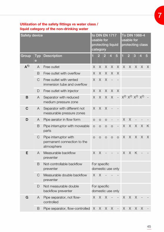
45
Utilization of the safety fittings vs water class / liquid category of the non-drinking water
Safety device to DIN EN 1717 usable for protecting liquidcategory
To DIN 1988-4 usable for protecting class
Group Type
Description 1 2 2 4 5 1 2 3 4 5
A1) A Free outlet X X X X X X X X X X
B Free outlet with overflow X X X X X
C Free outlet with vented immersion tube and overflow
X X X - -
D Free outlet with injector X X X X X
B A Separator with reduced medium pressure zone
X X X X - X2) X2) X2) X2) -
C A Separator with different not measurable pressure zones
X X X - -
D A Pipe aerator in flow form o o o - - X X - - -
B Pipe interruptor with moveable parts
o o o o - X X X X K
C Pipe interruptor with permanent connection to the atmosphere
o o o o o X X X X X
E A Measurable backflow preventer
X X - - - X X K - -
B Not-controllable backflow preventer
For specific domestic use only
C Measurable double backflow preventer
X X - - -
D Not measurable double backflow preventer
For specific domestic use only
G A Pipe separator, not flow-controlled
X X X - - X X X - -
B Pipe separator, flow-controlled X X X X - X X X X -
7
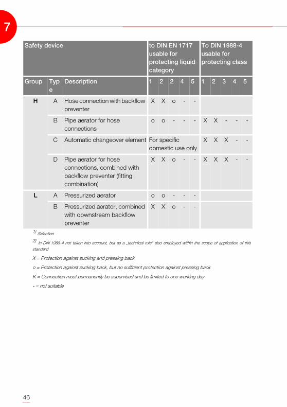
46
H A Hose connection with backflow preventer
X X o - -
B Pipe aerator for hose connections
o o - - - X X - - -
C Automatic changeover element For specific domestic use only
X X X - -
D Pipe aerator for hose connections, combined with backflow preventer (fitting combination)
X X o - - X X X - -
L A Pressurized aerator o o - - -
B Pressurized aerator, combined with downstream backflow preventer
X X o - -
1) Selection
2) In DIN 1988-4 not taken into account, but as a „technical rule“ also employed within the scope of application of thisstandard
X = Protection against sucking and pressing back
o = Protection against sucking back, but no sufficient protection against pressing back
K = Connection must permanently be supervised and be limited to one working day
- = not suitable
Safety device to DIN EN 1717 usable for protecting liquidcategory
To DIN 1988-4 usable for protecting class
Group Type
Description 1 2 2 4 5 1 2 3 4 5
7
47
8. APPLICABLE DOCUMENTS
[1] DIN 2000: Zentrale Trinkwasserversorgung - Leitsätze für Anforderungen anTrinkwasser, Planung, Bau, Betrieb und Instandhaltung derVersorgungsanlagen - Technische Regel des DVGW
[2] TrinkwV: Verordnung über die Qualität von Wasser für den menschlichenGebrauch - Trinkwasserverordnung
[3] DIN 50930-6: Korrosion der Metalle - Korrosion metallischer Werkstoffe imInnern von Rohrleitungen, Behältern und Apparaten beiKorrosionsbelastung durch Wässer - Teil 6: Beeinflussung derTrinkwasserbeschaffenheit
[4] DIN 1988-6: Technische Regeln für Trinkwasser-Installationen (TRWI) - Teil 6:Feuerlösch- und Brandschutzanlagen (Dezember 1988)
[5] DIN 1988-6: Technische Regeln für Trinkwasser-Installationen (TRWI) - Teil 6:Feuerlösch- und Brandschutzanlagen (Dezember 2002)
[6] DIN 1988-2: Technische Regeln für Trinkwasser-Installationen (TRWI) - Teil 6:
[7] DIN 1988-4: Technische Regeln für Trinkwasser-Installationen (TRWI) - Teil 6:
[8] DIN EN 1717: Schutz des Trinkwassers vor Verunreinigungen in Trinkwasser-Installationen und allgemeine Anforderungen anSicherheitseinrichtungen zur Verhütung vonTrinkwasserverunreinigungen durch Rückfließen
[9] DIN 18381: VOB Vergabe- und Vertragsordnung für Bauleistungen - Teil C:Allgemeine Technische Vertragsbedingungen für Bauleistungen(ATV); Gas-, Wasser- und Entwässerungsanlagen innerhalb vonGebäuden
[10] DVGW W 551:Trinkwassererwärmungs- und Trinkwasserleitungsanlagen -Technische Maßnahmen zur Verminderung desLegionellenwachstums - Planung, Errichtung, Betrieb undSanierung von Trinkwasser-Installationen
8

48
8
49
9. INDEX
AEqualization, hydraulic 12Protective measure 37Degree of protection 18, 27, 32, 38Protective measure 37Shut-off fitting 39Short-term connection 18Connection, indirect 9Pharmacy 40Medical practice 40Implementation basis 14Outlet, free 23, 24, 38, 39, 40, 41, 42, 43Nominal volume flow 10Outdoor fitting 11
BBath water 42Construction site 37Detrimental effect 17Treatment unit 41Treatment chair 41Vent opening 31Right of continuance 5Industrial water 38Notation system 18Lead pipe 8Letter combination 21
DAttic conversion 11Metering unit 8Pressure difference 24Printing machine 39Booster system 39, 40Pressure reducer 25Flow position 28DVGW mark of conformity 43
EInstallation position 27Individual protection 15, 17, 32Point of supply 17, 30, 37, 38, 42Point of supply 5, 7, 11, 13, 16Point of supply, vulnerable 15, 40Point of supply, not vulnerable 15
FFire-extinguishing pipe 8, 9Fire brigade 9Film development machine 39Fishpond 39Flow rate 11Flow direction 17, 27, 31, 32Prison sentence 5Filling and draining station 10
GGalvanic applications 38Garden point of supply 44Hazard 17Hazard potential 37Fine 5Dishwasher 24, 40, 43Public Health Department 4Glass washing facility 40Limit value 3, 8Rubber membrane 25, 26
HShower head 15Heating filling 13, 14, 43High-pressure cleaner 44
ILaw for the Protection Against Infections 5Inspection 29Installation 5, 7
KCold water supply 11Inspection 4Inspection opening 27Force comparison principle 29Hospital 41Hospital fitting 41Kitchen fitting 42
LLaboratory 40Laboratory, accredited 4Legionella 12, 16Legionella problem 12Required fire-extinguishing water volume 9Fire-extinguishing water pipe 10Fire-extinguishing water pipe, wet/dry 10
MMachine connection 43Material 7Minimum nominal diameter 9Installation specifications 23Mouth-flushing tab 23
NNominal diameter 8Non-drinking water 7, 13, 15, 17, 18, 26, 27, 28, 31,32, 37, 38, 42Non-drinking water level 23, 26, 27, 30, 31, 32, 33,38, 41, 42, 43Non-drinking water level 38
9

50
PPackage solution 13 Nursing home 41Mushroom aearator 32Planning 5, 7Sample 4
QQuality requirement 5
RCleaning agent 44Pipe aerator 2, 16, 21, 30, 31, 32, 33, 37Inside pipe surface 11Pipe separator 14, 16, 21, 28, 29, 39, 40, 43, 44Pipe interruptor 18, 25, 26, 39, 41, 42, 43Back-pressing 13, 15, 17, 23, 24, 28, 38Back-flowing 13, 15, 16, 17, 23, 28Backflow preventer 13, 14, 16, 17, 24, 25, 27, 28,30, 31, 32, 37, 38, 43Sucking-back effect 18, 26, 32, 39Sucking back 13, 15, 16, 17, 23, 24, 28, 38
SCollective protection 15, 16, 17, 32Sanitary object 23Foam 23Hose 37Hose aerator 30, 31, 32, 38Hose connection 43Protective measure 7Safety valve 11Safety value 28Safety fitting 7, 13, 14, 15, 17, 18, 21, 29, 37,Safety device 15Safety combination 32, 42, 43, 44Stagnation 8, 41Risk of stagnation 11Stagnation section 12Stagnation water 11Production of stagnation water 11Standpipe 37Stagnaton pressure 25Floor pipe 12Pipe system regulation valve 12System separator 24, 25, 38, 40, 43System separation 9
TSeparation pressure 28, 29, 30Separation position 28Split, atmospheric 25Drinking water 3, 5, 7, 17, 37Drinking water heater 11, 12Drinking water pipe 11, 15, 18, 26, 28Drinking water quality 5, 7Drinking Water Regulations 3, 5, 12, 37Drinking water supply 3Dripping water drainage 33Dripping water limiter 33
USurveillance period 4Changeover element, automatic 31Vacuum 31Vaccum built-up 26Bottom rinsing pipe 40Examination 3, 4
VControl 5Failure probability 37Contractual basis 14Contamination 7, 8Volume flow 24
WWall hydrant 8, 9Tub filling and shower fitting 31, 42Tub filling and shower fitting 15Heat insulation 12Warm water system 16Warm water supply system 12Washing machine 24, 43Washstand 42Washstand fitting 15, 42Water pressure 24, 28, 29, 30, 31, 39Taking water 29Water outlet situation 37Water class 17Change in water 17Water supply company 3Water change 8, 9, 12Water meter 12Water meter system 16WC basin 27, 42WC cistern 15Contract for services 5
ZDental surgery 40Drawing symbol 21Circulation 12Circulation system 12Feeder pipe 10
9

51
NOTES

52
NOTES