Embed Size (px)
Citation preview
* iJ -03 ~~~~~O0~6
AUG 1I 0 993
Ray Wassel, Project OfficerCommittee on Technical Bases
for Yucca Mountain StandardsNational Academy of SciencesRoom 4562001 Wisconsin Avenue, N.W.Washington, D.C. 20007
Dear Mr. Wassel:
SUBJECT: INFORMATION REQUESTED BY THE COMMITTEE ON TECHNICAL BASES FORYUCCA MOUNTAIN
I have reviewed your letter of July 16 which outlines documents andinformation sought by the Committee as reflected in your notes from theMay 27-29 meeting. As you have requested, we have compared your outline toour own analysis of notes taken from this meeting. We have found them to belargely in agreement with the contents of your letter. The items that havebeen requested are listed below (in bold typeface) along with the status ofeach tem and clarifications of our understanding of the requests, whereappropriate:
(1) NUREG/CR-3964: We have recently transmitted the 8 copies that yourequested. Volume I and Volume II of this NUREG/CR were both sent.
(2) Phase 2 Performance Assessment and document on the potential for largereleases: The Phase 2 work is scheduled for publication in April 1994.However, the NRC staff has made presentations about the development ofthis methodology which could be provided to the Committee. NUREG-1327,"Initial Demonstration of the NRC's Capability to Conduct a PerformanceAssessment for a High-Level Waste Repository," was published in May 1992and describes the NRC staff's performance assessment capabilities atthat time. We would be happy to provide copies of this report to theCommittee, upon request.
NRC staff has identified one additional request related to performanceassessment as follows:
Current results of the performance assessment modeling, as it pertainsto C-14 releases: Presentation materials and a recent paper byDr. Richard Codell on this subject are enclosed with this letter. Wehope that this information will be sufficient.
(3) Effectiveness of Markers: A list of references and a summary of the 10CFR Part 60 regulatory history that relate to the persistence andeffectiveness of institutional controls are currently being prepared.These can be provided to the Committee by early November.
93O902067 e3010l
PDR WASTE

2
(4) 10,000 year time period over which compliance must be demonstrated: Asummary of the Commission's previous comments to the EnvironmentalProtection Agency about the time frame for compliance can be provided bythe end of September.
(5) De minimis levels of Iodine: Review of NRC staff notes do not indicateany committee requests for information from NRC in this area. We wouldappreciate clarification of the Committee's request related to thisissue.
(6) ICRP-46 report: Further information on this report has already beenprovided.
(7) Regulatory responsibility for waste transportation: We understand thatthe summary of regulatory responsibility for transport of high-levelwaste may no longer be needed. We will take no additional action onthis matter unless there is a request to do so.
We have outlined our understanding of the requests made to us by the Committeeand have indicated their current status, including where appropriate, theschedule for providing the information. We will continue to do our best tomeet the evolving needs of the Committee. If there are changes to theCommittee's needs or if our interpretation of the requests differs from whatis sought, please let me know.
Sincerely,
Margaret V. Federline, ChiefHydrology and Systems Performance BranchDivision of High-Level Waste Management, NMSS
Enclosures:As stated
DISTRIBUTION (Distro w/o enclosures) except Central Fil
Central File BJYoungblood, HLWM JJLinehan, HLWM HLHP r/fMVFederline, HLHP RLBallard, HLEN JHolonich, HLPD NMSS r/fCNWRA LSS LPDR ACNWPDR
*See Previous Concurrence A -OFC HLHP* HLHP* HLHP| i
NAME JRFirth/cj NAEisenberg MVFederline
DATE 8/ /93 08/ /93 8/1¢,93 {1 _
G:\JRF\WASSEL.MVFC COVER E COVER & ENCLOSURE N = NO COPY

I i- . 7 A
2
(5) De minimis levels of Iodine: Review of NRC staff notes do not indicateany committee requests for information from NRC n this area. We wouldappreciate clarification of the Committee's request related to thisissue so that we might be able to accommodate this request.
(6) ICRP-46 report: Further information on this report has already beenprovided. NRC staff have identified one additional request related toperformance assessment as follows:
Current results of the performance assessment modeling, as itpertains to C-14 releases: Presentation materials and a recentpaper by Dr. Richard Codell on this subject are enclosed with thisletter. We hope that this information will be sufficient.
(7) Regulatory responsibility for waste transportation: We understand thatthe summary of regulatory responsibility for transport of high-levelwaste may no longer be needed. We will take no additional action onthis matter unless there is a request to do so.
We have outlined our understanding of the requests made to us by the Committeeand have indicated their current status, including where appropriate, theschedule for providing the information. We will continue to do our best tocontinue to meet the evolving needs of the Committee. If there are changes tothe Committee's needs or if our interpretation of the requests differs fromwhat is sought, please let me know.
/5/Margaret V. Federline, ChiefHydrology and Systems Performance BranchDivision of High-Level Waste Management, NMSS
DISTRIBUTION
Central File BJYoungblood, HLWM JJLinehan, HLWK HLHP r/fMYFederline, HLHP RLBallard, HLEN JHolonich, HLPD NMSS r/fCNWRA LSS LPDR ACNWPDR
|OFC |HLHP C |HLHP (& I 0" HLHP I
| NAME JRFirth/cJ s O HAEi erg MYFederline
DATE 8/ 6 /93 08/( /93 8/ /93-~ -1s~lersue
b: \,JKr \WAZ1btL.r1Vr
C - COVER E COVER & ENCLOSURE N NO COPY

I
GEOCHEMICAL MODEL FOR C TRANSPORT IN UNSATRATED ROCK
Richard B. CodellU.S. Nuclear RegulatoryCommissionWashington D.C. 20555(301).504.2408
ABSTRACT
.`C in a geologic nuclear waste repository could bereleased to the gaseous phase and escape to the acces-sible environment through partially saturated fracturedrock Interaction with e carbon system in the ground canlead to retardation of C A mechanistic Interpretation of"C retardation and release Is provided by a model thatcouples nonisothermal gas low and water saturation,carbon distribution based on local equilibria among gas.liquid and solid phases, and C and "C transport. Reposi-tory heating Is predicted to volatilize carbon from the liquidphase and to promote calcite precipitation "C transport Isretarded principally by ncorporation in the aqueous phase.A portion of arty released "C can be fixed In precipitatedcalcite for thousands of years.
INTODUVCTION
Under oxidizing conditions In high-levol nuclearwaste repository, I'C In nuclear waste might be releasedas "'CO, Any such gas scaping the engineered barrerwill be incorporated in the existing carbon system of thegeosphere, and be transported along wMh gaseous anddissolved carbon.
Several recent studis addressed vC gaseoustransport at the Yucca Mountain repository environmentusing smplified modes of goachemical rtardaxton'XAccurate modeling of C transport requires coupling ofrelations between ths source, heat low, two phase fluidflow and the distribution of chemical spoes among solidliquid, and gas phases. Interphase exchange of carboncould result In a significant retardation of released It.thereby delaying is arrival at the accessible environment.This paper reports on a mechanistic model or the geo-chemical interaction of 'C for a HLW repository In partiallysaturated rock.
The C tport model consists of dueo parts:
Willila M. MurphyCenter for Nuclear WasteRegulatory AnalysesSan Antonio TX 78228
* A geochemical model describing te state of allcarbon species In the gas, liquid and solid phasesfor a representativ volume of partially saturatedrock;
* A flow and transport model for movement of totalcarbon through tho system which consists of anumber of connected volumes or ce1s1; and
* A model of 0 migratior as a trace quantity In egeneral movement ot total carbon.
GEOCHEMICAL MO
A carbon system geochemical model which Incor-porates al reactions of primary sgnficance to C trans-port in partially saturted ractured rodc can be based onlocal chemical equilibrium and Muss and harge conseva-tion in a representative volume. Chemical reactions in themodel comprise carbonate equilibria among aqueous spe-cies, dissociation of water, vaporliquld equilibria for CO,an H, nd calcite disolution and precipitation. In add-ion to the aquos spece In theso oquilibria, the presentmodeu l icudes Nto represent other aqueous cations.The racton represented in he present model are givenbelow.
H20(l) C02(aq)2 N- + CO (1)
co fie * CO: (2)
H + ' O2 0 (3)
CaCO,3(s) sk G2 + CO (4)
CO2cg) 42 C02(aq) (S)
1959

I1960 RADIOACTVE WASTE MANAGEMET
Local charge balance in the model aqueous phaseis represented by equating sums of aqueous cation andAnion equivalents. Local mass conservations or carbonand calcium are maintained within each cell, and the massof sodium is conserved In the aqueous phase.
Given the total masses of C, Ca and other species,mass of water, and the temperature, pore volume andpressure of each cell, the above relationships lead to a setof nonlinear algebraic equations which are solved simul-taneousty to characterize local equilibrium In each cell foreach time step. Equilibrium constants for reactions I to 5are functions of temperature only at one bar pressure.
ity coefficients are functions of Ionic strength, and aregenerated from an extended Debye-Hackel equation.Calcite i permitted to precipitate or dissolve, and themodel solution becomes undersaturated with respect tocalcite in ts absence. The partial pressure of CO2 Is calcu-lated from the activiy of aqueous CO assuming Ideal gasrelations.
TOTAL CARBON TRANSPORT MODEL
The calculation of transport of total carbon through themodeled system Is performed by sequential iteration In thefollowing steps:
* Local chemical equilibrium is calculated In each cellat time t using the geochemical model;
* inputs and outputs to each cell are determined froman Independent flow model for the next time stept+ at In the present model, only edvective trans-port by gaseous low i allowed. Therefore, theInput ot CO to a cell I determined only by thepartial pressure of CO, In the previous cell or up-stream boundary and t low of the transportinggas trom tat cell. Gaseous ow and condense-tionwevaporation of water is accounted fw indepen-dently as part of the low model and input to thechemical model.
* Mass distrbuions e revised In th cels for fimestep t+ A using h gochemical model with updat-ed temperature nd Uquid saturation stat.
The carbon transport algorithm In te precedingsteps simulates changes o the chemistry of each phase Inthe system as a function of tm and space. The carbontransport model determines the quantis of CO, gasmoving through t system of cels, a wall as the x-change rates ot carbon betwen the various phases.
"C TRANSPORT MOOEL
Any '4C released from the waste will constitute onlya small raction of the total carbon In the surrounding toCkThe I4 transport model uses te state and evolution oftotal carbon speclation to simulate transport through thesystem of trace amounts of '4 released nstantaneously ata particur cell. Treating 'C as trace sows eImple
formulation of the transport model and the use oft Enarsuperposition for more general. noninstantaneous sourceterms. '4 Is assumed to behave exactly In proption tothe total carbon, with no Isotopic fractionation. Howeradioactive decay removes 'C from the solid. liquid angas Inventories. '4C is removed from the liquid/gas phas.es i calcite precipitates from solution. It reenters thesystem previously '-contaminated calcite dissolves.The model assumes that calcite dissolves first from the 'v.
contaminated calcite Inventory before uncontaminated cal.cite rdissoives. The model further assumes that the "4C isdistributed homogeneously within the contaminated calciteof each cen.
MODEL APPLICATIONS
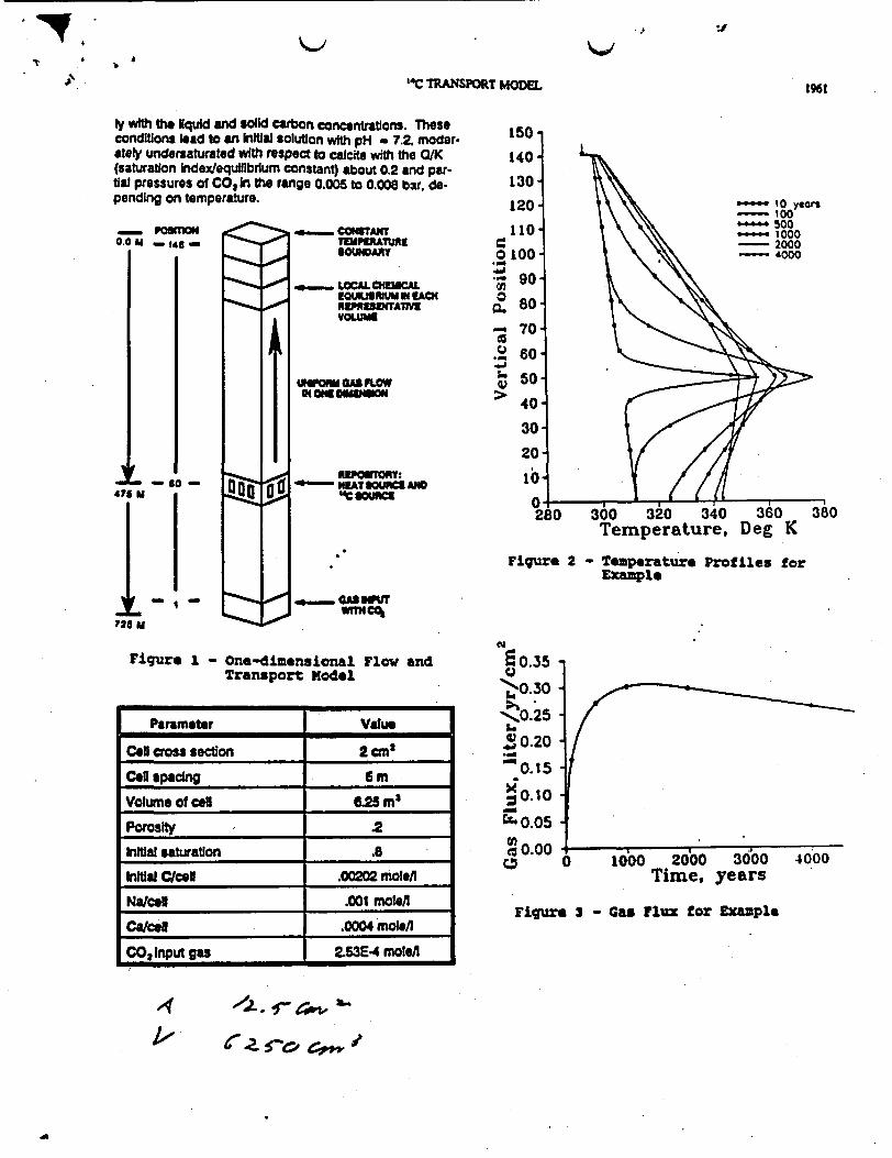
The present geochemical transport model has beenapplied to simplified examples in order to demonstrate therange of possible phenomena associated with the releaseand transport of '400 in partially saturated fractured rockThe model domain is a one-dimenslonal column of 45cells represented In Fig. 1, with constant hydraulic proper.ties and cross sction, passing through th center of ahypothetical repository plane, which Is located at cell 50.Water, gas, and relevant mineral chemistries, as well as thegeothermal gradient that resemble those observed atYucca Mountain are provided as Minal conditions. Thesystem chosen for the example was simple In order not toconfound ft results of the geochemical transport modelwith other phenomena. For example, gas is assumed toflow In the upward direction only, even though thermal.hydraulic smulations indicate an Initially outward gas flowIn a directions from a heated repository In partially saturat-ed tuft4 Additionally, trnsport of 4C Is by advection in tgas phase only, there Is no transport of '4C by water flowor diffusion in gas or water.
lime-dependent temperature a gas flux used inthe present example were generated from two-dimensionalcodes develop at NRC for predicting air flow throughYucca Mountai, and similar to ths models developed byAmptr and Ross' Temperature, represented in Fig. 2.was Calwated rom a two-dimensional thermal conductionmod which ncluded to geothermal gradient The ther-mal modal sumed constant Mal conductivity and auniform ial heat loading of 67 kinowatts per acre. Gasfou. shown in Fg.S, varied with time, but was assumed tobe uniforM throughout t one-dimensaional column.
Liquld aUrtion is Swn In Fig. 4. The temper-ature a gas flow models did not Include water saturationexplicitly. Therfore, an approxdmate empirical model forstraon of the column was derived from e results ofsImulato of twophase thermaly Induced circulation nearrepositorS in tll. The empirical model used in the ex-ample predc tha water saturation I 60% except within azone of about 0 mr above and below the repositolyfor a period of ss an 200 years. Other initial condl-tions nd paraetrs of the example sysem are given inthe table below. The input concentration of CO 1waschosen so t gaeous CO,would be in equilibnum initial-
T 1 A
'4C TRAffSPORT MODEL
l` with t liquid and solid Carbon concentrations. Theseconditions lead to an Initial solution wth pH 7.2r moder 150ately underuaturated with respect to calcite with the 0K 140-(saturation Index/equilibrium constant) about 0.2 and par-tia pressures of COt In the range 0005 to 0.008 bar de- 130 pending on temperature. sn
1961
- PCORm0.0 hi ~ g -
- u_ CowffTIPMUE
UNOARY
- LaC CCUEOWIRUN EACHrmESMAW1VoUAS
u a" FLOWIoGWOONmInSoN
0 100. 0
-Wu go.
0Q 80
- 70'
.2 60} 50
0> 40
30
20
*SM
1~475 1
i2 - SO -
I
- NETSOUNCE AND
00 320 340 360Temperature, Deg K
Figure 2 - Temperature Profiles forExample
_a @ GS fUWvmCO
Figure 1 - one-dimensional Flow andTransport Model
Parameter Value
Cell cross sectlon 2cm2
Cel pacing t m
Volume of Cell 25 m |
Porosity .2
Initial saturation .
InIUial C/cell .00202 molo/l
Na/cd .001 mobe/
Calcell .0004 molell
CO2 Input gas 253E4 moletl
050.35
0 30
'!0.25
* 020
0.15
10.10
540.05
02U0.004000
years
Flgure 3 - Gas Flux for Example
-4 /-S-G
A4

16 'AC P1962 RADiOAcIvE WASTE MAAGEMENT
140
130-
120-
110-
o 100-
,-~ 90-
O 80- o
_ 70-
Q 60-
so 50-
> 40-
30
20
L o 1U
tory plwa to ccount for gas rculation Oxpc*d nar torepository, and allows Interaction of the contamtnant bsiowas well as above the engineered barrier.
- 1o years1 00
- 500_ 1000
- 2000- '000
At 100 years, most of the "C has redistributed tothe liquid phase. The liquid and gas Inventories of 'Chave moved above the repository plane because of gastransport, even though the fraction of C In the gas phaseis small. The C In the calcite remains fixed until calciteredissolves. At S yeas, the gas and liquid Inventories of'C have moved further above the repository plane. Someof the calcite near the repository plane redissolves. re-leasing Its C Inventory, which In turn Is patily capturedby precipitating calcite further from the repository planewhere temperature continues to horease.
By 2000 years, nearly all C Is swept from thecolumn, except that which remains trapped in te calcite.By this time, calcite Is redissotng everywhere, so thecontaminated calcite acts as a long-term source of "C tothe system. Some of this residual "1C remains even at4000 years.
II
0. .
0.b 0.2 0.4 0.6Saturation
- Water Saturation toFiqure 4
Results for carbon model
Results for the carbon tansport modiFig. 5, which shows the distribution of carboamong the gas, liquid and solid phases for after repository closure. Initially, the carboncreases I the liquid phase end Increasas hIgas phases near te repository lve. At arepository, however, the carbon content of uld phases Increases, a reflection of gas hrpulse of CO2 initially volatilized from the Iqulrepository and transported. Increasing tmpcreasing soivent mass, and Increasing pH divolatilization all promote calcite precipitationrepository horizon.
At 500 years, the Initially volatilized Cbeen flushed out the top of th column. Thrtent continues to grow, spreading above axrepository level as temperature Increases. A40OO years th calcite progressively redissotliquid content of carbon Increases as the ro
Results of "C model
Deoendence on time of rele
O B I The model predicts t calcite starts to precipitateshortly after repository closure and then redissolves.Therefore, th timing of the release of "C from the waste isImportant to Its ultimate fate. C released after most cal-
r Example dte has precipitated win not be removed from the liquidand gas phases as effectively as " released during theperiod of active calcite precipitation. Fure 7 thows thecumulative release (as a fraction of the amount released)
el are given at el[ locations In Me column of '4C over a 500 yearsrn for each cell tie period from repository closure, as a function of thearlous times time tht th C pulse was released. This figure demon-
content do- strates the Iteresting phenomenon that "C released atthe solld and early tme Can ave at te end of the column later thanbovthe "C released subsequently.he gas and Rq.Ispot of the CONCLUS1ONSd ntear theerature, do- Nwerkal experints with a low and transportA to CO, model that Includ coupled nonisotermal geochemistry,near the pioid Insights to th behavior of C In a partially satu-
rated geologic repository fr nuclear waste. Applicationshave been made to a system resembling the proposed
0 pulse has repository at Yucca Mountai Nevada. Model resulse calcte con- show a significa redistution of autochthonous carbond below t among solid, liquid and gas phases, even in areas remoteU12000 and 1rom the repository plane. Carbon remains predomrnanalyhres wile the in aqu s solution in spite of t fact that near-field:k cools. heating esult In a reduction of liqd saturation, abundant
calci predpKaon, and Increased equilibrium fractionationof C02Into th gas phase.
Figure 6 shows the distibution of "C for each cellIn the gas, liquid and solid phases at varlous times for 104a of 'Ic released 15 m below the assumed repositoryplane at time zero. The It was released below the repos-
While not shown explicitly hi tS paper, transport of'IC released fm the repository would be generally retard-ed by a factor of approximaty 30 to 40 because of immo-bilization in the liquid phase. In addition, "C releasedearly during the period of solid calcite precipitation can be
IIIIIIIIIIN

'I
'4C TRANSPORT MODEL 1963
140
130
120
110
.2100 *-90
0 80 ,70
60
_J 505->, 40
30
20
10 i
0 _0.000
...... C gas - 100 years- - C liquid
- C calciteI
I
D-.-
140
130
120
110 .
C100.
* 90 .o 80 .
70
o 60 $0 50
> 40
30
20
10
00.000
.-- C gas - 500 years--- C liquid
- C calcite
I0113I
IIIIIII
-IIIIIIII
.1
IIII
II
"I
I I
0.001 . 0.002Moles C per Cell
0.001Moles C per
.
0.002Cell
140 .
130 .
120 i
110, .
~100iIt o .-
CLo 7- 0
0 40 .,
90
20
- 0 o60.0
1.. 50 1
> 40 130
20
10
0-0.000
-.--- C gas - 2000 yers- -- C liquid
C cakiteI
IIt
If
I5
0
II
140 1130 .,
120 .
110 I
< 100 .I
o, 801- 700
C; 60.o 50
0
30
20
140
0.000
II
-P--- C s - 4000 y~~~~~~~~~~~~~n* --- C S~~~~~~~~~~~uid j~~~~~-C cekite ,~~~~~~~~~~~~~~~~~~~~~
t
I
II
I1
.5
.5
i1
0.001 0.002Moles C per Cell
0.001Moles C per
0.002Cell
Fiqure 5 - Carbon content of gas 9 liquid and solid phases

C'10
1964 RADIOAVE WASTE MANAaeNT
140 -
130
120-
110
100 ..... C-14as 100 O ~~--- C142lquid
*w 90 -4014 Calcite
O 80-
70-0
450
> 40-
30-
20-
10 -
0 O.OE+OO0 4.OE-008 8.OE-008 1.2E-007
C-14 on Solid, Liq. and Gas
140
130-
120 -0 C04ga year
10- C-t4 Cacite
1 100 .
' 90* ____
o so _1
90
20
10 10.O ...................,,....... ., .'''''1
O.OE+000 4.OE-00 B.OE-ooaC-14 on Solid, Liq. and Gas
I
.t
140
130
120
110
100 too ..... C- 14 s 200 enO -C:14 ( d*w 9 0 - C-14 4 lcite
0 480
_ 70
30
20 30
2010
O.OE+000 8.OE-009 I.6E-008C-14 on Solid, Lq. and Gas
140
130
120'
110
r. 0o I ..... C-14 gas 4000 years0lO - -C-14 qud.
go - C-14 Calcite
0 80
_7
00
> 40
30
20
10
O.OE+OO0 4.OE-009 a.OE-009 1.2E-O08C-14 on Solid, Liq. and Gas
I
I
I
I
I
Fgqur 6 - C content of gas, lquid and solid pbass(NOTS: scales change)

C
'4C TRANSPORT MODEL l965
1. 00
095
W 0.90 ._O
e0 .8 -
2 0.80 - X=75a"- X=145 (TOP)
1. S. Ampter, S. RoW, Simulation of gas low beneathYucca Mountain, Nevada with a model based on keshwa-ter head, Proceedinas of the Svmooslum on Waste Man-agement Tucson, AZ, 2 915 (1990)
2 W.9. Light, T.H. Pigford, PL Chambre, and W.W.LLee Analytcal models for C-14 transport in a partiallysaturated, fractured, porous me". FOCUS 9 Proceed-Igs. Nuclear Waste Isolation hi the Unsaturated Zone,
American Nuclear Society, Lagrange Park, Illinois (1990)
3. RB. Knapp. An approximate calculation ot advec-live gasphase transport of 'C at Yucca Mountain, Neva-da, JContamlnnt Hdrolo=y j, 133 (90
4. JJ Nftao, Numerical modeling of the thermal andhydrological environment around a nuclear waste packageusing the equivalent contirnum approximation: HorizontalEmplacemenr, UCID-21444. Lawrence Livermore NationalLaboratory (1990)
.0.75
=0.70 .. .
I0.0 200.0Time
5 I I .
400.0 600.0 800.0 1000.0of Release, years
Figure 7 - Cumulative releaso by 2500.eare as a function of whenC vas released
fixed or a long period before repository cooHng leads toredissolutlon of the calcite.
Although simplified, the model demonstrates thecomplex nature of the geochemical processes affecting '1Ctransport Results of the simulation depend trongly onmodel assumptions, and retardation would change underdifferent conditions of chemistry, hydrology, tempeatue orgas low. We contemplate coupling geochemistry andcarbon transport models with more realistc two or trdimenslonai treatments of heat and mass trfr nea arepositoy hI partially saturated tlf, which would iudetransport In the gas and iquid phases nd allow tor molecular diffusion.
DISCLAIMER
The contents of th paw are solely the opinionsof the authors, and do not necessarily constitu th officialpositions of either the U.S. Nuclear Regulatory Commisinor the Center for Nuclear Waste Regulatory Analyse.

-a
MODEL FOR RELEASE OF GASEOUS C MON SPENT FUEL
Richard CodellU.S. Nuclear Regulatory Commission
Washington D.C. 20555(301) 504-2408
ABSTRACT for the Yucca Kountain repository.
1'C is contained in cladding, intergrainboundaries and U02 in spent nuclear fuel,and can be released as gaseous CO2 in anoxidizing environment. Approximately 2.5of the inventory can be released quicklyfrom gap. grain boundary and claddingsurface. 'C within cladding can be releasedupon oxidation of the metal. but is probablya minor source. Most l'C is contained in U02fuel, and can be released when the fueloxidizes. Releases from fuel depend ondiffusion of oxygen through the grain bound-aries and a layer of U30,, and diffusion of1'CO2 out through same two layers A modelof U02 oxidation was based on experimentaldata, and used in a model for 1'C release.This model s demonstrated on a hypotheticalrepository in an unsaturated environment,and shows a strong dependence on the time atwhich containers fail.
INTRODUCTION
The release of 14C from disposednuclear waste at the partially saturatedYucca Mountain site Is a potentially impor-tant regulatory issue because in the gaseousform t could migrate quickly to theatmosphere. Currently, Parkl estimatesthat there will be about 78,000 curies of 1'Cin the projected 70,000 MTHK of spent fuelin the repository, an order of magnitudegreater than would be allowed to be releasedfrom the repository under present regu-lations2 .
Estimating the rate and quantity ofrelease of "'C to the accessible environmentrequires models for the release from thewaste form, flow of gas and liquid throughthe geosphere, and interaction of the Camong water, air and rock3. The presentpaper reports on a model for gaseous releaseof "C from spent fuel, currently being usedin NRC's total system performance assessment
Background
The main reservoirs for 1'C in spent fuelare the cladding, cladding/fuel gap, grainboundaries, and the fuel itself. ost of this1'C must frst oxidize to be released as gas.Although elemental carbon is generally stable atlow temperatures, thermodynamics in air favorsthe formation of gaseous compounds such as CO2and methane. Ionizing radiation may also play arole in oxidation of carbon. Van Konynenburg'noted that 'CO2 was released from cladding nan oxidizing environment with a radiation levelof 10,000 rad/hr and a temperature of 275C.Kopp and Munzels however showed "4CO2 releasesfrom "C-doped zirconium sheets at temperaturesas low as 200C wth virtually no radiation.
COMPONENTS OF MODEL
The model of 1'C release assumes that uponcontainer failure, a portion of the Cinventory n the claddlng/fuel gap, grainboundaries and cladding surface will be releasedquickly. 4C will also be released fromcladding, structural metals and spent fuel atrates controlled by oxidation of the substrates.The balance of this paper presents the bases forthe assumed release mechanisms, and a demonstra-tion of the model for a hypothetical repositorysituation.
Cladding ntegrity
Protection of the fuel by the cladding hasbeen ignored. While this is likely to be apessimistic assumption, it may be difficult toprove to the contrary that the cladding wouldsurvive long periods of time. Factors that mightlead to early cladding failures include; () asmall number of undetectedpinholes or cracks instored fuel rods, generally considered to belower than 1, (2) swelling of fuel rods withconsequent splitting of cladding when oxidized,(3) hydride reorientation after removal from
22

ifIIl oF
"C RELEASE MODEL
reactor core. (4) fuel rod pressurization,and (5) mechanical breakage caused byhandling errors, container buckling orearthquakes.
Prompt Release Fraction
Experiments on ruptured spent fuelindicate that upon cladding failure, 0. 5percent of the inventory may be releasedfrom the fuel/cladding gap7. In addition tothis release, Smith and Baldwin$ showed thatas much of 2 percent of the total spent fuel"C. inventory was released from zircaloycladding heated to 350C for 8 hours. Therelease rate is an Arrhenlus relationshipconsistent with diffusion out of a thinoxide layer with an activation energy E ofbetween 19 and 25 Kcal/mole. In argon with atrace of air, release rates were lower by afactor of about 10, indicating that thecarbon was in a reduced state and had tooxidize before being released. Release of1'CO2 from 'C-doped zirconium sheets showeda similar dependence on oxygen'. If therelease of 1'C from the cladding oxide layeris governed by diffusion of either oxygen or14COz, it is possible to estimate the upperbound of release rate for the temperaturerange of interest, approximately 7C to350C. One-dimensional molecular diffusionthrough the film of thickness L can beexpressed by the partial differentialequation:
for temperatures as low as 75 C, release of the1"C by diffusion out of'the oxide film would benearly complete within 10,000 years, and possi-bly much less time. In the present model, theentire quantity of 2'C contained in the promptrelease fraction." 2. 5 percent of the spent fuelinventory, is assumed to be released to thegeosphere at the time of container failure.
Table 1 - Releases of 1 C from Cladding Oxide
T-OC ta-yrs t,-yrs
E-19 E-25Kcal/m Kcal/m
350 .00091 .00091
250 .017 .043
150 1.3 - 13
75 169 7800
asc . D a2CEF axa (1)
where D is the diffusion coefficient, C isthe concentration of oxygen or 1"CO2 and xis the distance measured from the edge ofthe cladding toward the center. Equation(1) can be solved analytically' in terms ofthe dimensionless parameter Dt/l2 Theconcentration profile, and hence fractionreleased at other temperatures, is relatedto this parameter. For a constant filmthickness, time to reach an equivalentconcentration profile is inverselyproportional to the diffusion coefficient;i.e. t - t1 D/D2 . The ratio D/DZ can berelated by the Arrhenius equation to be:
Release of "C from Cladding Metal
The cladding oxidation layer is about 10microns thick initially. The cladding metal it-self is on the order of 0.6 mm thick, and con-tains the bulk of the 14C in the cladding. Uponoxidation, the 1 C contained in the metal couldbe released as 14C0 2 . azarelli1 0 presents sev-eral empirical formulas for the post-transit-ional weight gain of xircaloy due to oxidation.The release model for cladding oxidationconservatively adopts the most pessimisticparameters. The fractional release of 1Ccontained in the cladding metal per year is:
am 456.9x10"-11 7 3 / r e-At (3)m
where I is the radioactive decay rate of C.The -model additionally assumes that "CO2 isreleased at the rate that the metal oxidizes,and that other irradiated structural metal isincluded with the zircaloy cladding as a sourceof "'C.
Release of 1"C from UO2
The largest inventory of 1 C is containedin the spent fuel. The exact form is unknown,but may be a solid solution of elemental carbon,carbides and oxycarbides with the U 1. Themodel for release of 1 C from spent fuel makesthe following assumptions:
* U 2 oxidizes at a rate controlled by thediffusion of oxygen through two barriers; thegrain boundaries and a film of higher oxide ofU02 ;
FW 1)DI .e_'fia'Ft
T;(2)
where R is the gas law constant. Relying onexperimental data of Smith and Baldwin'. thetime for an equivalent release at tempera-ture T2 is illustrated in Table 1, assumingnearly all "C Is released in time tj - 8hours at Ti-350*C. Results indicate that
I _;t - - -

I
*; RADIOACnlVE WASTE MANAGEMENT
J
* The oxygen concentration at the oxide/fuelboundary is zero because all oxygen is beingconsumed by fuel oxidation;
* 1 CO will be released at the unoxidizedfuel surface at the rate the spent fueloxidizes;
* 1'Co2 must diffuse outward through theoxide film and grain boundaries, and;
* Concentration profiles for both oxygen andare at steady state, although the posi-
tion of the fuel/oxide boundary changes withtime.
The present model assumes that thefuel mass can be represented by twoconcentric spheres as shown in Fig.l. Theouter sphere represents the grain-boundarydiffusion barrier and has the equivalentspherical diameter of a fuel fragment, about0.2 cm. The inner sphere represents thediffusion barrier through the oxide film onthe surface of the fuel grain, with adiameter of about 20 microns. The boundaryconditions for the model are zero oxygenconcentration at the fuel/oxide interfaceand atmospheric oxygen concentration at theouter diameter.
and differs for the oxide layer and grainboundary layer. The boundary between the spentfuel grain and the oxide layer changes as theoxide layer grows, and is governed by thediffusion rate of oxygen at the interface:
* ' NI D 8(5)
where r is the radius of the fuel/oxideinterface and p is the density of the oxide.The term No, is the conversion factor for U02 interms of moles U 2 oxidized per mole 0 reachingthe boundary. For the temperature ranges likelyto be encountered in the repository, most of theoxide formed will be U307 stoichiometricallyl.For the purposes of the present analysis, N istaken to be 3 i.e., 3 moles of U02 will be oxi-dized by 1/2 mole 02.
For steady state concentration of oxygenin both layers, Eqs. 4 and reduce to:
dr',dt
(6)(C - C1) N.,
[De~l B. DJ R R P
where Ca - the concentration at the interfacebetween the UN2 and Ut30, taken here to be zero,and C, - concentration of oxygen at the surfaceof the fuel fragment, taken here to be the volu-metric concentration in the atmosphere, 0.2moles/22,400 cm3. is. the initial grainradius and R, is the radius of the fuelparticle. The rate of growth of the oxide layerdepends on the diffusion coefficients Do and D1which are functions of fuel temperature.Between r and R,, diffusion coefficient Do ap-plies, and between R, and R, D applies. Thetemperature of the fuel is estimated externallywith a transient heat conduction model.
Parameters for the U02 oxidation modelwere estimated from data collected on the deg-radatlon of unLrradiated and spentfuels" 1 2 1 ' 1u 17 1 8 . Quantitative data on fueloxidation in air was basically of four types;Thermal CravimetrLc Analysis (ToA), dry bathanalysis. ceramography and x-raycrystallography. Observations of ceramographicsections of spent fuel gave quantitativeinformation about the sizes of fuel grains andthe rate of growth of the oxide. In addition,ceramography gave qualitative information aboutthe mechanisms of oxidation; e.g. the fact thatthe film of oxide appears to be growing at aconsistent rate throughout the sample indicated
Figure 1 - Conceptual Model for U02Oxidation
Diffusion of oxygen through the fuelgrain will be governed by the followingpartial differential equation:
E r2 E (r -r)
where C - oxygen concentration, t - time, r- radius from the center of the sphere, andD - diffusion coefficient. The diffusioncoefficient D is a function of temperature,

0 i
* P. .
Q"C RELEASE MODEL 25
that diffusion of oxygen through grainboundaries and cracks probably was muchfaster than the diffusion across the oxide
layer itself.
X-ray crystallography gave qualitativeinformation on the chemical species of the
oxide formed at different temperatures,useful for defining the conceptual model.Among the more interesting indications ofx-ray crystallography was the observationthat for temperatures below about 200-C theoxide formed was primarily U40e, even though
it appeared to be U307 stoLchLometrically12.
At higher temperatures (and possibly at
lower temperatures for long periods of time)U308 was the oxidation product, and because
of its lower density would swell the fuel
rods and promote cladding failure'.
Data on sample weight gain from TGA
and dry bath analysis and film thicknessfrom ceramography at fixed temperatures wereput into the form of 'conversion fractions
of U02 to U307 versus time. Any conversion to
U308 in the samples was ignored. Parameters
of the model were then chosen that best
matched conversion versus time for the 8
temperatures at which the data were
available. The parameters allowed to vary
were grain size, fragment diameters, Do, DI
at reference temperature T-200C, andactivation energy E (assumed to be the same
for both layers). Parameters giving thebest comparisons are shown in Table 2. The
parameter identification did not explicitly
take into account differences between
fragment sizes, grain sizes or types offuel, and the parameters represent theensemble of all LWR fuel. Representativeresults of the model/data comparison aregiven in Fig.2.
Table 2 - Numerical Values of 14C NodalCoefficients
Model Parameter Value
Grain rad. cm 0.001
Fragment red., cm 0.1
Ref. oxide diff. 5.256xO-1coef. cm2/yr
Ref. grain 5.942xlO03diff. coef. cm/yrReference T, C 200
E, Kcal/mol 32
0.984
C.
00 Time, hours 1,000
Figure la - Model/prototypeoxidation - 2SO C
comparison for 302

* 26,.
-i
0.00733
C
b.
IC
00
RADIOACTIVE WASTE MANAGEMENT
The radial gradient of 1"C0h is steady.but because of radioactive decay, less 14C vllleave the fuel fragment than eminated from the
* / fuel/oxLde interface. A similar model which in-cludes C decay was evaluated for parametervalues likely to lead to the largest differencecaused by neglectingradLoactLve decay. Results
* of this analysis led to the conclusion thateffects of radioactive decay of 1 C on the fluxcan be ignored. Therefore the flux of 1 C from
INV the fuel fragment is taken as the rate of re-lease from the fuel/oxLde interface.
0"-model OVERALL 1 C MODEL CONSERVATISM
12.000 The 1"C release rate model is probablyconservative for the following reasons:Time, hours
Figure 2b - Model/prototype comparison forU02 Oxidation - 1029C
The model for the release of 1'CO2 from thefuel matrix is similar to the UO2 oxidationmodel. Diffusion of 14CO 2 through the fuelgrain boundary layer and oxide layer will begoverned by the following partialdifferential equation:
r ' 12 ad (D ) - Ic, (7)
where C - 14CO concentration and 1 is thedecay coefficient for "C. The outer boundarycondition sets the 14CO2 concentration tozero at r - R1. At the inner boundary r',14CO2 enters the oxide layer from the justoxidized fuel. The gradient of "ICO2 concen-tration C is set by the diffusive flux:
ac"W11
* ZLrcaloy is a highly corrosion resistant mate-rial. and it is likely that it would protect thefuel following container failure for a substan-tlal period of time. Protection of the fuel evenfor a few hundred years would have a substantialimpact on the calculated release rate becausethe greatest potential for release is the periodduring which the fuel temperature is highest.
* Most of the C in the fuel, cladding andhardware is likely to be in a reduced state, andmust first oxidize to be released in the gaspathway. While kinetic considerations might re-strict the formation of gaseous compounds of the1"C in the fuel, the model conservativelyassumes that any C available to be oxidized isconverted to 14COZ. A portion of the "'C in thespent fuel may be in a chemical form that is noteasily released. Experimental data in whichspent fuel was heated to temperatures of up to45O C in oxygen indicated that up to half of the"C remained in the solid, and was not releasedas 1'CO2 It.
* The model ignores resistance from the failedcontainer; i.e., once 14COZ is released from thefuel fragment no credit is taken for diffusionthrough the long length of a failed fuel rod, orthrough very small holes in the container.
RESULTS OF "AC RELEASE MODEL FOR A HYPOTHETICALREPOSITORY
The model demonstrates the relative impor-tance of the waste form compartments containingthe &"C, and the temperature at which wastepackage failure occurs. Figures 3 and 4 showrelease rates of C calculated by the model fora hypothetical unsaturated repository. Releaseis calculated from 66 randomly placed spent fuelcontainers which are assumed to begin to failonce their temperatures fall below the boilingpoint of water. The two figures differ by theassumed lifetimes of the containers of either200±100 years or 1000±300 years after cool -down.
, 3M - et4:R2D dt
(e)
where K is the initial inventory of 14C. The14C diffusion model depends on the UOz oxida-tion model to provide the position of themoving boundary and the source flux of "CO2at the inner boundary as the oxide layergrows. Release of I"CO2 at the outer boundaryof the fragment is calculated from the con-centration gradient at that boundary:
Bloc 2 aC 0IRS (9)
where q - the rate of release from the frag-oent, curies/year and D - the diffusion co-efficient in the grain-boundary layer.

I "C RELEASE MODEL 27a
normally distributed. The shorter containerlifetime leads to greatly increased releasesof 1 C because of the dependence of theoxidation rates on temperature. Conversely,waste packages remaining intact for timescloser to their design basis lifetimes havegreatly reduced releases of gaseous 14C. Thecurrent EA 2 limit for 1"C release to the ac-cessible environment is shown for reference,although the results presented here refer toreleases from the waste packages to the geo-sphere only. In both cases, the UO2compartment was the largest contributor,while very little was released from theoxidation of cladding and metal.
pLANs FOR FURTHER MODEL DEVELOPMENT
The 1 C source term model is based onan abstraction of several complex processes.The simplifying assumptions taken in themodel are:
* The fuel is represented by concentricspheres, of a single set of dimensions;i.e. , the irregular shape of the fragmentsand grains is not taken into account.
* No effects of the container or cladding onthe diffusional processes are taken into ac-count.
* The increase in surface area caused byoxidation of the grains is not taken intoaccount.
* While there are some direct data onrelease of COt from cladding and thegrain/gap inventory, data on releases fromthe largest inventory in the fuel itself arelacking.
Future versions of the model willstrive to relax some of the limitations inthe present version. In particular,development will concentrate in two areas:
a Develop a transient modal The presentmodel considers only steady stateconcentrations of oxygen and 1*CO2 in thefuel. Thermal gravimetric analysis data onsome samples at relatively low temperatureindicates a period of slow Initial weightgain, followed by a substantially higherrate. This result has been interpreted asthe transient diffusion of oxygen throughthe grain boundaries prior to oxidation ofthe grains. At high temperatures wherediffusion coefficients are large, there isrelatively little difference between theconversion of large fuel fragments andcrushed samples, Indicating that the grainboundary diffusion is fast. At lower
temperatures, the difference between whole andcrushed samples is much more evident. While thesteady state model appears to fit the data well,it may in fact be portraying the transient dif.fusion as a much slower rate of conversion,especially t lower temperatures. This couldlead to inaccurate predictions of conversionrates at low temperatures for times much largerthan the period of 12,000 hours in the longestexperiment. A transient model for diffusionwould alleviate this inconsistency.
* Incorporate variations of grain sizes and oth-er material properties within samples Thepresent model assumes that the oxidizing fuelcan be characterized by a single set of parame-ters. Actually, each sample of fuel oxidized inthe laboratory consisted of grains of varyingsizes, and material properties determined by theposition of the sample in the fuel rod anddistance from the pellet edge. Furthermore, thefuel would be expected to vary from one rod tothe next in the same core, and from one set ofspent fuel to another, depending on such factorsas reactor type, burnup and fuel manufacturer.Variability in the fuel should be factored intothe model to the degree possible.
CONCLUSIONS
A preliminary model has been developed forthe release of 14C from spent fuel containersfor a hypothetical repository for spent fuel inthe unsaturated zone. This model includesphenomena responsible for the release of 1 Cfrom several compartments in spent fuel.Preliminary results indicate that the spent fuelitself would be the major source of 1 C, withrelatively minor amounts released from the othercompartments. The '1C release model is beingused in conjunction with a gas flow and trans-port model for NRC's Iterative Performance As-sessment, Phase 2 to estimate potentialreleases of 1 C to the accessible environment atthe proposed Yucca Mountain repository.
DISCLAIMER
The contents of this paper are the soleopinions of the author, and do not represent theposition of the Nuclear Regulatory Commission.
REFERENCES
1. Park, U.S., Regulatory overview and recom-mendations on a repository's release of carbon-140, Science Applications International Corp.

-P..
28 , RADIOACTlVE'
San Dego, California (1992).
2. U Environmental Protection Agency,40CFR Prt 191, Federal Register, vol 50, pp38006-38089 (1985).
3. Codell, R.B. and W.. Murphy,"Geochemical model for C transpor inunsaturated rock", Proceedings of the 1992International High Level Waste ManagementConference, Las Vegas Nevada: 1959-1965(1992).
4. Van onynenburg, RA., C.F. Smith, HV.Culham, and C.H. Otto, Behavior of carbon-14 in waste packages for spent fuel in arepository in tuff", UCRL-90855, LawrenceLivermore National Laboratory (1984).
S. Kopp, D., and H. Munzel, Release ofvolatile carbon-14 containing products fromZircaloy" J. Nuclear Materials 173:1-6(1990).
6. Enziger, RE, and R. Kohli, Lov-temperature rupture behavior of Zircaloy-Clad pressurLzed water reactor spent fuelrods under dry storage conditions-, uclearTechnologX 67:107-'123 (1984).
7. Wilson, C.N., "Results from NNWSI series3 spent fuel dissolution tests, PNL-7071.Richland, Washington: Battelle PacificNorthwest Laboratories (1990).
WAS-M MANAGEMEbrr �./
13. EzLger. I.E., and H.C Buchanan, Long-term, low-temperature oxidation of FUR spentfuelS WHC-EP.0070 iechland, Washington: West-inghouse Hanford Co (1988)
14. Einzlger, . E. Effects of an Oxidizing At-mosphere in a Spent Fuel Packaging Facility-Proceedints of FOCUS 91, AmericanNuclear Soci.ety: 88-99 (1991).
15. Einziger, R.E. Evaluation of the Potentialfor Spent Fuel Oxidation Under Tuff RepositoryConditions*, EDL-7452, Rchland, Washington,Engineering Development Laboratory (1991).
16. Woodley, .E., RE. Einziger, and H.C.Buchanan, "Measurement of the oxidation of spentfuel between 140 and 225C-, Nuclear Technologr85:74-88 (1989).
17. Enziger, R.E.. S.C. arschman, and .C.Buchanan, Spent-fuel dry-bath oxidation test-ing", Nuclear Technolorgv 94:383-393 (1991).
18. Thomas, L.E., OD. Slagle, and R.E.Einziger, BNonuniform oxidation of LWR spentfuel in air", J Nuclear Material 184:117-126(1991).
19. VanKonrnenburg, RA. "Carbon-14 Releases",presentation at Nuclear Waste Technical ReviewBoard Full Board Meeting, Las Vegas, Nevada,Oct.14 16, (1992).
8. Smith, H.D., and D.L. Baldwin, Aninvestigation of thermal release of C-14from PWR spent fuel cladding", Proceedingsof FOCUS 89. Las Vegas, Nevada: 46-49(1980).
9. Carslaw, H.S., and J.C.Jaeger,Conduction of Heat in Solids, Oxford,England: Clarendon Press (1959).
10. Cazarelli, F., D. Jorde, R. anzel,"Review of PWR Fuel Rod aterside CorrosionBehavior", Electric Power ResearchInstitute, Palo Alto California (1980).
II. Van Konynenburg, .A. caseous Releaseof Carbon-14: Why the High-Level WasteRegulations Should be Changed, Proceedingsof the 1992 International High Level VasteManagement Conference, Las Vegas Nevada:313-319 (1991).
12. Einziger, R.E., H.C. Buchanan, L.E.Thomas, and R.B. Stout, Oxidation of spentfuel in air at 75 and 195C. Hlih-LeelRadioactive aste Management , 1449-1457(1992).

I 'C RELEASE MODEL 29
25.00 -
cn
W 20.00 -
P
T 15.00-I
ra.o
10.00 .
.
W. 5.00
n o o o o o
- PAUht..
k ^ - * * * ^-
oeeeo TOTAL FROM 66Deese GAP AND GRAINa &FUEL*+*+*CLAMOING
Canister I
METRIC TONS
Lifetime200 ± 100 years
j - - n o o o o0.00 -----------.... ,.
0.0. . I I r- . . . r- . . . . X . . * 2000.0 4000.0
TIME,
r
6000.0YEARS
rr aII Ir T 1TrT8000.0 10000.0
Figure 3 - Rlease of 14C from 66 randomly placed containers inrepository in unsaturated tuff. Short Container Lifetime
a hypothetical
U
XV
I
VUSa
:
25.00 -
20.00 -
15.00 -
10.00
5.00 -
GOe" TOTAL FROM 66 METRIC TONSG6600 GAP AND GRAIN&e*e FUEL***** CLADING
^0o o o o
EPA Limit
- 8 e
L -
Canister Lifetime-1000 i 300 years
--- o o -
u.uu . b . . . . . . . . . . . . . . . . . . . . . . . . . . . . . . . . . . . . . . . .
0.0 2000.0 4000.0 iTIME,
f000.0 8000.(['EARS
10000.0
Figure 4 - Release of "C from 66 randomly placed containers in a hypotheticalrepository in unsaturated tuff. Long Container Lifetime

Detailed Example of the IPA Process in aSpecific Discipline: 14Carbon
Richard B. Codell, Senior Hydraulic Engineer
Hydrologic Transport SectionHydrology and Systems Performance BranchDivision of High-Level Waste Management
301/504-2408
Rex G. Wescott, Senior Hydrologist
Hydrologic Transport SectionHydrology and Systems Performance BranchDivision of High-Level Waste Management
301/504-2167
ACNW WORKING GROUP MEETING ON PERFORMANCE ASSESSMENTDECEMBER 16. 1992
DIVISION OF HIGH-LEVEL WASTE MANAGEMENT
ACNW - 66

14CARBON RELEASES FROM YUCCA MOUNTAINREPOSITORY
* 14Carbon associated with spent fuel
* Oxidized to carbon dioxide gas
* Transported in the gas phase in unsaturated rock
* Realistic assessment of impacts of 4Carbon requires coupling of source release, heat flow,two-phase fluid flow, and distribution of carbon among solid, liquid and gas phases
* Assessment of dose impacts
ACNW WORKING GROUP MEETING ON PERFORMANCE ASSESSMENTDECEMBER 16, 1992
DIVISION OF HIGH-LEVEL WASTE MANAGEMENT
ACNW - 67

RELEASES OF 14CARBON FROM SPENT FUEL
* Initial cladding oxide and crud
* Grain boundary and cladding gap
* Zircaloy oxidation
* Oxidation of fuel
ACNW WORKING GROUP MEETING ON PERFORMANCE ASSESSMENTDECEMBER 18. 1992
DIVISION OF HIGH-LEVEL WASTE MANAGEMENT
ACNW - 68
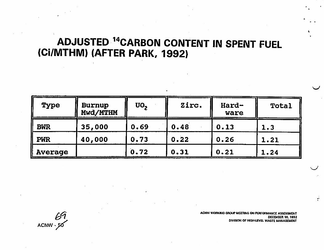
ADJUSTED 14CARBON CONTENT IN SPENT FUEL(Ci/MTHM) (AFTER PARK, 1992)
I Type | Burnup U02 Zirc. Hard- TotalMwd/HTHM ware
BWR 35,000 0.69 0.48 0.13 1.3
PWR 40,000 0.73 0.22 0.26 1.21
Average I 0.72 0.31 0. 21 1.24
b6 iACNW -d'
ANW WORKING GROUP MEETING ON PEIUORMANCE ASSESSMENTDECEMBER 16. 1992
DISION OF HIGH-LEVEL WASTE MANAGEMENT
.,
MODEL FOR RELEASE OF 14 CARBON
* '4Carbon released quickly from grain boundaries, cladding/fuel gap, and initial zirconiumoxide
* Minor releases from oxidation of cladding and other metals
* Major releasable inventory from U02 fuel
ACNW WORKING GROUP MEETING ON PERFORMANCE ASSESSMENTDECEMBER 16. 1992
DIVISION OF HIGH-LEVEL WASTE MANAGEMENT
ACNW - 70

)II-I-
;u.
I-G
0Iiw
wION)�ZZK�
I-
NU
U
had Rod
14 140
C C&
'calose
08,
4Cla 1
. 1
usshb
nls
Ao2ms cw
a m,,s, UC
ACMM "Pswea
Locaton of Radlknucides h Spen Fuel and Potnl Reim of C-14(AptWd, l. l, 189) '11� �-Z
zu-

SHRINKING CORE MODEL FOR FUEL OXIDATION
Low conversion High conversionOxide Layer* Unoxided Fuel
m 6 ~ me> X Tim* 0 aS*
1Reactionl I.111 *il ~~~~~iI zone ;
R 0 R R 0 R R 0 RRadial position
ACNW WORKING GROUP MEETING ON PERFOFMANCE ASSESSMENTWG E E M B R l . WN 92DFVISION OF HIGH-UEL WASTE MLAGENT
ACNW -
7;Zi

C-14 Gaseous Release Model v
oxygen
ACtNW WORKNG GROUP MEETING ON PERFOfMANCE ASSESSMENTDECEMBER la. 1992
DISION OF N*GH-LEVEL WASTE MANAGEMENT
ACNW -4

FUEL OXIDATION MODEL ASSUMPTIONS:
* No oxidation until canister fails
* No protection of fuel by cladding
* Oxygen diffuses through two layers:o outer layer representing grain boundarieso inner layer representing oxidized fuel
* Oxide is U 307 stoichiometrically
* Oxygen concentration zero at inner boundary
* Oxygen profiles in layers are at steady state
AMNW WORKING GROUP MEETING ON PERFORMANCE ASSESSMENTDECEMBER 16, 1992
DIVISION OF HIGH-LEVEL WASTE MANAGEMENT
ACNW - 74

PARAMETER IDENTIFICATION AND MODELVERIFICATION
* Grain diameter from micrographs of fuel (20 microns)
* Outer layer diameter taken as fragment size (2mm)
* Weight gain from thermal gravimetric analysis and dry bath experiments between 1 10 and250 degrees C (PNL)
* Activation energy and diffusion coefficients adjusted for best fit to oxidation data on fuelfragments in 8 temperature ranges
* Little data found on 14Carbon releases from fuel oxidation
ACNW WORKING GROUP MEETING ON PERFORMANCE ASSESSMENTDECEMBER 18. 1992
DIVISION OF HIGH-LEVEL WASTE MANAGEMENT
ACNW - 75

a
o Data ~ ~ ~ ~ ~ ~ ~ ~ ~ ~ ~ ~ ~ ~ ~ ~ ~ ~ ~ a DtModel~ ~ ~ ~ ~ ~ ~ ~ ~ ~ ~ ~ ~~~~~~~~oe
0~~~~~~
,,600ata0~~~~
Tm, hours Ti me, hours 1,000
TIme hours n . o rsT
1.00
0~~~~~~~~~~~~
0 0~~~~~~~~~~~~~~~~0
Dab 0~~~~~~~
0~~~~~~~~0 400~~~~0 I . Tie0o r
*1Unu rIgurw

Transient Oxidation Effects
C0
@ 0.10C0:-
0 5 10 15A, hours
Not included in fuel oxidation model
9 'I'lI II IC C

25.00
U)0-
W- 20.00
1 15.00
0w 10.00
I 5.00
Release from Engineered Barrier- -* -- * W_ O -
* ,!,- -
o .is TOTAL F.|t Ij~~~~~AP A t t-,
bf L^^|FUEL*-*~*^* CLADDI NO
EPA Limit Canis~X ~- 200:
Affer a' @ -t _ -t
w ~ ~ ~ ~ ~ ~ ~ ~ ~ ~ ~ ~ ~ I t. .................. b ~.. i
4*1 tj,-PA I N
HIE 1 RC l t- *'t-
ter Lifetime± 100 years*,,hl
,,-. .- -.
0.00
0. 0I' r z iP . . . . ii,1' * * I I *s * * I | 1I Ir- r, T r .
6,^1( 0 0. 0I . . . . T- . -, , . , , . I , I- I , . I T-
4 0 0 0. ()
TIME, YEARSIs(()(.( I ()()0.(
- 25.00
C)
= 20.00
15.00
00w 10.00U)4:
- 50
94 5.00
oe4c TOTAL F1 c.Io t I C C TONSGAP AND GRAINFUEL
***.* CLADDINO
Release from Engineered Barrier
I .. s ... .. _
EPA Limit Cani1000Aflrsi
- - ~- - +
.
--- ---
ster Lifetime± 300 years
ceSdn'"i, . .II-- -
0.00 _ __^s
.. ^b
., , , , , , , . . I . . . . I
l.....T-Tr
0.0 2000.0 4000() (; (.(TriNE, YEAWI'i
, . .., .
.1H)00.( I (f)0()).0... ... I.... --
,$0
. C (1. .

1
GAS FLOW AND 14CARBON TRANSPORT MODEL
* Based on model of Ross et al. (TGIF)
* 2-D Finite difference modelo Quasi steady state; transient temperature field but steady gas flow
* Equivalent porous medium combines fractures and matrix
* Single phase -- water-saturated gas only
* 4Carbon transport by advection with retardation factor
ACNW WORKING GROUP MEETING ON PERFORMANCE ASSESSMENTDECEMBER 16. 1992
DIVISION OF HIGH-LEVEE' WASTE MANAGEMENT
ACNW - 78

J= 1
JHETA=N 14
REPOSITORY CROSS SECTION FOR GAS FLOW MODEL

I .
J=. I-ILEFT+NC1=1 ILEFT b. lNCT
_ ~ ~ ~ ~ ~ ~ ~ ~ ~ ~ ~ ~ ~~. _+~ _ _ _ _. _ _ _ _ _ _ -;. - -. - -- -- - - -
_ __ , REPOSITORY fLUX.i- - - --- - - - Kw REPOSITORY LuxII . .. . . . .. .. . . .. ... . .. ... .. .. . . . . . . .
- - - - --- J---=N - --- ............ .. . JT
GEOTHERMAL FLUX
REPRESENTATION OF REPOSITORY X-SECTION FOR HEAT TRANSFER
(6;e

=
TYPICAL X-SECTION 500 YRS
.001 M/YR
V Sowv v v A V V' V v V vV ~~ V V V vvv v v V ~~~ . 'V V .VA.V V.
.A. %*.... v,. v....IAO.NZ O D
t,
I-
WEAKNESSES OF '4CARBON FLOW AND TRANSPORT MODEL
* Does not include 2-phase flow
* 2-D Steady state only - Cannot include third dimension or time
* Retardation coefficient may not adequately capture interaction of '4Carbon with water androck
ACNW WORKING GROUP MEETING ON PERFORMANCE ASSESSMENTDECEMBER 16. 1992
DIVISION OF HIGH-LEVEL WASTE MANAGEMENT
ACNW - 80

a
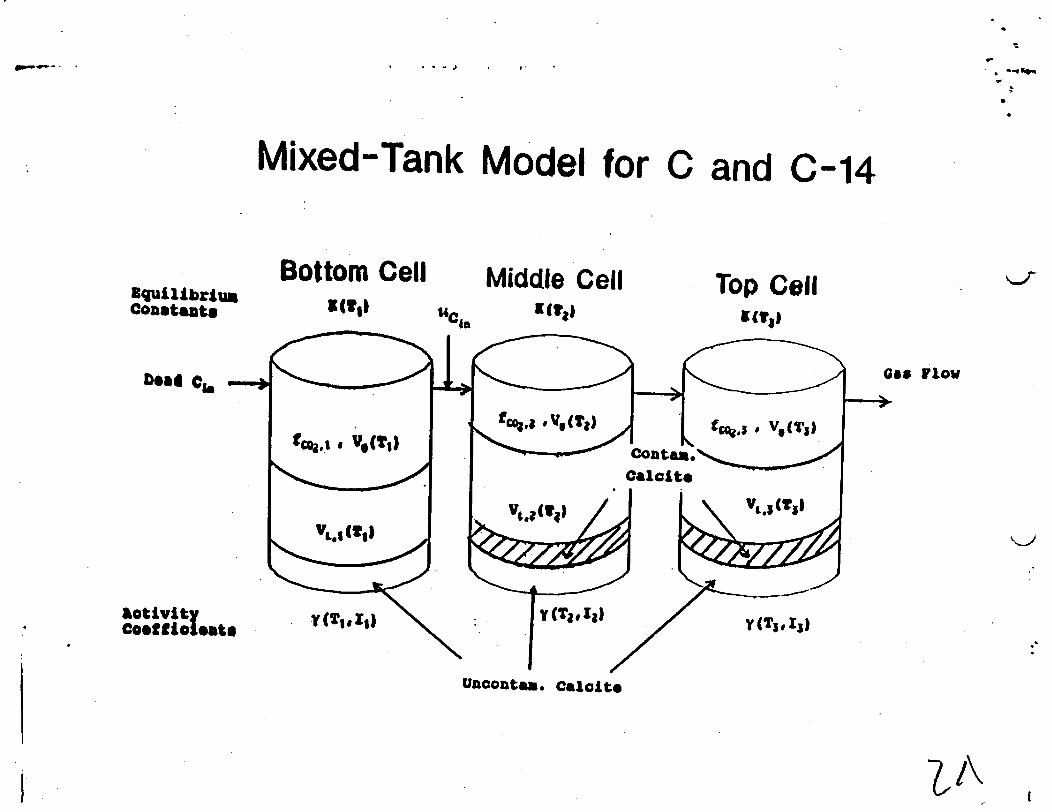
GEOCHEMICAL MODEL FOR TOTAL CARBON
* Calculate chemical equilibrium in each tank
* Determine output from tank to next tank in gaseous phase (no water moves)
* Sum new inventories of carbon and recompute coefficientso Eq. Coefficients function of To Activity coefficients function of T and ionic strength
* Repeat calculations of chemical equilibrium for next time step
K>
ACNW WORKING GROUP MEETING ON PERFORAANCE ASSESSMENTDECEMBER 16. 1992
ODVISION OF Hm-LHEVEL WASTE MANAGEMENT
ACNW - 83
I XI^ .
Mixed-Tank Model for
1
C and C-14
Bottom CellquillbrIu
Cotants
Middle Cella(t,,x(1II
Top CellITa1"cift
Gas lowDead C -
activityCo9tol lat.
uncotea. Calcite
LI\I

i C)
140
130
120-
.110-
k
0
0o"
o
0
0:c;._
s0"
100-
90
80
70-
60-
50-
40-
30-
20-
10-A'-
* e-- 10 yearsA-- 100*-" 500
1000-- 2000
nwwo4000OS)OO~~~~~~~~~~~
A :~~~~
.~~~~~~~~~~~~~~~~~~~~~~~~~~~~~~~~~~~~~~~~~~~~~~~~~~~~~~~~~~~~~~~~~~~~~~~~~~~~~~~~~~~~~~~~~~~A ;~~~~~~~~~~~~~~~~~~~~~~~~~~~~
0
a - a=
- _ _ _~~~~~~~~
0.2 0.4 0.6Saturation
4.
0.8 1.0
Figure 4 - Water Saturation for Example
.*Ia
a

- _+~ - .. -. _- . . *.* - a * . a -,____
C.)
lSm 0.35- ;
to ~025
4i 0.20 /
0.150.10
N 0.05
Cd .00 . . .. .. ,
0 0 1 000 2000 3000 {1000Time, years

IMPACT OF ' 4CARBON RELEASE
* Cumulative Release at Accessible Environment
* Lifetime doses to regional and global populations, and average dose to individuals
o Near field concentrations in air v
o Water from Wells
ACNW WORKING GROUP MEETING ON PERFORMANCE ASSESSMENTDECEMBER 10. 1992
DIVISION OF HIGH-LEVEL WASTE MANAGEMENT
ACNW - 85

4
.1p
T
SUMMARY
* NRC is developing a suite of models for the release and transport of "4Carbon
o Release from waste form
o Gas flow and advective transport
o Geochemical interaction of 4Carbon
* Models are simplified and preliminary, but allow experimentation with parameter variationsto determine sensitivities
ACNW WORKING GROUP MEETING ON PERFORMANCE ASSESSMENTDECEMBER 16, 1992
DIVISION OF HIGH-LEVEL WASTE MANAGEMENT
ACNW - 86

-'V
TENTATIVE CONCLUSIONS
* Significant concerns exist about likely size of gaseous 4Carbon releases and theuncertainty in estimates of those releases
* Even after substantial research and analysis, the remaining uncertainties may make itdifficult to evaluate compliance with EPA's '4Carbon release limit
* Direct exposure to airborne '4Carbon probably insignificant dose
k-I
ACNW WORKING GROUP MEETING ON PERFORMANCE ASSESSMENTDECEMBER 16. 1992
DIVISION OF HIGH-LEVEL WASTE MANAGEMENT
ACNW - 87