Embed Size (px)
Citation preview
Live Tank Circuit BreakersApplication Guide
2 Application Guide | ABB Circuit Breakers
Edited byABB AB High Voltage Products Department: Marketing & Sales Text: Tomas Roininen, Carl Ejnar Sölver, Helge Nordli, Anne Bosma, Per Jonsson, Anders Alfredsson Layout, 3D and images: Mats Findell, Karl-Ivan Gustavsson SE-771 80 LUDVIKA, Sweden
ABB Circuit Breakers | Application Guide 3
Table of contents
1. Introduction 81.1 What is a circuit breaker? 81.2 Why do we need circuit breakers? 91.3 Different types of switching 91.4 Disconnecting and withdrawable circuit breakers 91.5 Circuit switcher 111.6 Environmental aspects 11
2. Live tank circuit breaker designs and operating principles 122.1 Historical development 122.2 Main components 13
2.2.1 Breaking unit 142.2.2 Support insulator 142.2.3 Operating mechanism 142.2.4 Support structure 14
2.3 Additional components 152.3.1 Grading capacitors 152.3.2 Preinsertion resistors 152.3.3 Cabinets for central control 15
2.4 SF6 Interrupters 162.4.1 SF6 gas 162.4.2 Principles of arc extinction 162.4.2.1 Thermal regime 172.4.2.2 Dielectric regime 182.4.3 Earlier interrupter designs 192.4.4 SF6 puffer circuit breakers 192.4.5 SF6 self-blast circuit breakers 222.4.6 Configuration of the moving contacts 25
2.5 Operating mechanisms 262.5.1 General 262.5.2 Spring-operated mechanism 272.5.3 Motor Drive 302.5.4 Pneumatic-operated mechanism 312.5.5 Hydraulic-operated mechanism 312.5.6 Hydraulic spring-operated mechanism 312.5.7 Other types of operating mechanisms 32
3. Current switching and network stresses 333.1 Short-circuit currents 33
3.1.1 Standardized time constant and asymmetry 353.1.2 Peak withstand current 36
3.2 Terminal faults 373.2.1 Transient Recovery Voltage (TRV) in single-phase networks 373.2.2 TRV in three-phase networks 40
3.3 Short-line faults 433.4 Initial Transient Recovery Voltage (ITRV) 453.5 Out-of-phase conditions 463.6 Switching of capacitive currents 47
3.6.1 De-energizing of capacitive loads 47
4 Application Guide | ABB Circuit Breakers
3.6.2 Recovery voltage 503.6.3 Energizing of capacitor banks 51
3.7 Inductive load switching 533.7.1 Switching of shunt reactors 533.7.1.1 Current chopping and resulting overvoltages 543.7.1.2 Reignitions 573.7.1.3 Overvoltages and overvoltage limitation 583.7.2 Switching of no-load transformers 59
4. Mechanical stresses and environmental effects
60
4.1 Mechanical loads 604.1.1 Static loads 604.1.1.1 Dead weight 604.1.1.2 Static terminal load 604.1.1.3 Ice load 624.1.1.4 Wind load 624.1.2 Dynamic loads 634.1.2.1 Dynamic loads due to operation 634.1.2.2 Dynamic current loads 644.1.3 Seismic load 654.1.3.1 Measures to increase seismic withstand levels 67
4.2 Combination of loads 674.3 Influence of extreme ambient temperatures 684.4 Gas properties 69
4.4.1 Effect of ambient temperature 694.4.2 Moisture content in SF6 gas 70
4.5 Sound effects of circuit breaker operation 714.5.1 Standards 714.5.2 Sound level as function of distance 71
5. Thermal stresses 725.1 Thermal limits 72
5.1.1 Derating of rated current due to temperature 725.2 Temperature rise test 735.3 Temperature rise at current overload 745.4 Influence of site altitude 76 6. Insulation requirements
78
6.1 Insulation co-ordination 786.2 Overvoltages 78
6.2.1 Short-duration power frequency voltage 786.2.2 Lightning impulse 786.2.3 Chopped impulse 806.2.4 Switching impulse 80
6.3 Insulation levels 816.4 Dielectric tests on circuit breakers 84
6.4.1 General 846.4.2 Combined voltage test 846.4.3 Other voltage tests 85
Table of contents
ABB Circuit Breakers | Application Guide 5
6.4.3.1 RIV (Radio Interference Voltage) tests 866.4.3.2 Partial discharge test 866.4.3.3 Pollution test 866.4.3.4 Tests on low-voltage circuits 86
6.5 Atmospheric correction factor 876.6 Installation at high altitudes 886.7 Environmental effects and insulator shapes 89
6.7.1 Creepage distance and pollution 896.7.2 Environmental classes according to IEC 906.7.3 Environmental classes according to IEEE 91
6.8 Clearances in air 926.9 Insulating material 93 7. Application
94
7.1 Transmission line circuit breakers 947.1.1 Faults on overhead lines 947.1.2 Switching of no-load transmission lines 957.1.2.1 Voltage factor 957.1.2.2 Line charging current 957.1.2.3 Reclosing 967.1.2.4 Shunt compensated transmission lines 967.1.2.5 Series compensated transmission lines 967.1.3 Classification 96
7.2 Power transformer circuit breakers 977.2.1 Asymmetry and d.c. time constant 987.2.2 No-load switching conditions 987.2.3 Synchronization 997.2.4 Classification 99
7.3 Capacitor/filter circuit breakers 997.3.1 Recovery voltage and voltage factors 1007.3.2 Inrush current 1007.3.3 Rating and classification 101
7.4 Shunt reactor circuit breakers 1017.4.1 Operating conditions 1027.4.2 Reignitions 1037.4.3 Elimination of reignitions 1037.4.4 Shunt reactor switching tests 1037.4.5 Classification 104
7.5 Bus couplers 1047.6 Special applications 104
7.6.1 Railway applications 1057.6.1.1 Railway applications with a power frequency less than 50 Hz 1057.6.2 Series capacitor by-pass switches 1057.6.3 HVDC filters 1067.6.4 SVC (Static Var Compensator) 107
7.7 Instrument transformers and relays in combination with live tank circuit breakers
107
7.8 Controlled switching 108
6 Application Guide | ABB Circuit Breakers
8. Standards and tests 1098.1 Standards 109
8.1.1 IEC 1098.1.1.1 Time definitions according to IEC 1108.1.2 ANSI/IEEE 111
8.2 Circuit breaker testing 1118.3 Type tests 112
8.3.1 Dielectric tests 1128.3.2 Radio Interference Voltage (RIV) tests 1138.3.3 Temperature rise tests 1138.3.4 Measurement of the resistance of the main circuit 1138.3.5 Short-time withstand current and peak withstand current tests 1138.3.6. Mechanical and environmental tests 1148.3.6.1 Mechanical operation test at ambient temperature 1148.3.6.2 Low and high temperatures tests/tightness tests 1158.3.6.3 High temperature test 1168.3.6.4 Humidity tests 1178.3.6.5 Ice tests 1178.3.6.6 Static terminal load test 1178.3.7 Making and breaking tests 1188.3.7.1 Preparation for tests 1188.3.7.2 Single-phase/three-phase testing 1188.3.7.3 Unit test/full pole test 1198.3.7.4 Direct tests 1198.3.7.5 Synthetic testing 1208.3.7.6 Summary of test duties 1218.3.7.7 Terminal fault 1218.3.7.8 Short-line fault 1218.3.7.9 Out-of-phase making and breaking tests 1228.3.7.10 Capacitive current switching 1228.3.7.11 Shunt reactor current switching tests 123
8.4 Routine tests 1238.5 Test reports 123
8.5.1 Type test reports 1248.5.2 Type test reports of independent laboratories 1248.5.3 STL organization 1248.5.4 SATS organization 125
9. Reliability, maintenance and life cycle costs
126
9.1 Failure statistics 1269.2 Electrical and mechanical life 1269.3 Maintenance 1289.4 Condition monitoring 1289.5 Life cycle costs 1299.6 Environmental aspects 129
10. Selection of circuit breakers 131
Table of contents
ABB Circuit Breakers | Application Guide 7
This document gives background information for selection of the best possible circuit breaker solution for each particular application.
The guide addresses utility, consultant and project engineers who specify and apply high-voltage circuit breakers.
The guide addresses live tank circuit breakers in general for voltages up to 800 kV.
The most usual requirements on a circuit breaker are mentioned, such as the capabilities to handle network stresses, insulation levels, mechanical forces and ambient conditions.
The construction of circuit breaker poles and operating mechanisms will be mentioned only briefly since these parts are described in ABB Buyer’s Guide for Live Tank Circuit Breakers.
Scope
8 Application Guide | ABB Circuit Breakers
1. Introduction
1.1 What is a circuit breaker?A circuit breaker is an apparatus in electrical systems that has the capability to, in the shortest possible time, switch from being an ideal conductor to an ideal insula-tor and vice versa.
Furthermore, the circuit breaker should be able to fulfill the following requirements: 1. In the stationary closed position, conduct its rated current without producing
impermissible heat rise in any of its components.
2. In its stationary positions, open as well as closed, the circuit breaker must be able to withstand any type of overvoltages within its rating.
3. The circuit breaker shall, at its rated voltage, be able to make and break any pos-sible current within its rating, without becoming unsuitable for further operation.
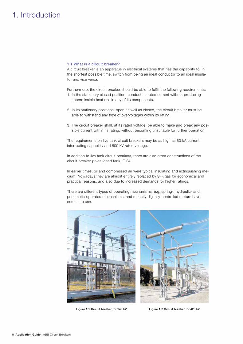
The requirements on live tank circuit breakers may be as high as 80 kA current interrupting capability and 800 kV rated voltage.
In addition to live tank circuit breakers, there are also other constructions of the circuit breaker poles (dead tank, GIS).
In earlier times, oil and compressed air were typical insulating and extinguishing me-dium. Nowadays they are almost entirely replaced by SF6 gas for economical and practical reasons, and also due to increased demands for higher ratings.
There are different types of operating mechanisms, e.g. spring-, hydraulic- and pneumatic-operated mechanisms, and recently digitally-controlled motors have come into use.
Figure 1.1 Circuit breaker for 145 kV Figure 1.2 Circuit breaker for 420 kV
ABB Circuit Breakers | Application Guide 9
1.2 Why do we need circuit breakers?The circuit breaker is a crucial component in the substation, where it is used for coupling of busbars, transformers, transmission lines, etc.
The most important task of a circuit breaker is to interrupt fault currents and thus protect electric and electronic equipment.
The interruption and the subsequent reconnection should be carried out in such a way that normal operation of the network is quickly restored, in order to maintain system stability.
In addition to the protective function, the circuit breakers are also applied for intentional switching such as energizing and de-energizing of shunt reactors and capacitor banks.
For maintenance or repair of electrical equipment and transmission lines, the circuit breakers, together with the disconnectors, earthing switches or disconnecting cir-cuit breakers with built-in disconnecting function, will ensure personnel safety.
1.3 Different types of switchingThe requirement to switch any current within the circuit breaker’s rating includes dif-ferent making and breaking conditions:
− Terminal faults, short-circuits in the vicinity of or near the circuit breaker. − Short-line faults, short-circuits to ground along the transmission line within a few
kilometers of the circuit breaker. − Out-of-phase conditions at which different parts of the network are out of
synchronism. − Intentional switching of capacitor banks, shunt reactor banks, no-load
transformers, no-load lines and cables. In this connection controlled switching ought to be mentioned. This is described in ABB Controlled Switching, Buyer’s and Application Guide.
The different switching conditions will be explained in Section 3, Current switching and network stresses.
1.4 Disconnecting and withdrawable circuit breakersIt has been mentioned that the circuit breaker is an important element in the sys-tem, either as a ”stand-alone circuit breaker” in a conventional substation or as an integrated part of a compact switchgear assembly.
The modern solutions with Disconnecting Circuit Breakers (DCB) and Withdraw-able Circuit Breakers (WCB) make it possible to develop new types of switchgear constructions.
The purpose of the compact switchgear assembly is to simplify the switchgear and at the same time to improve the reliability of the system.

10 Application Guide | ABB Circuit Breakers
The different types of compact switchgears have one thing in common elimination of the conventional disconnectors in the system. Disconnectors have basically the same failure rate as circuit breakers, but need more frequent maintenance.
The DCB is a circuit breaker that satisfies the requirements for a circuit breaker as well as a disconnector. This is described in IEC 62271-108.
Ratings for current and voltage are the same as for a circuit breaker, while the insulating levels comply with those for disconnectors. Disconnecting circuit break-ers are normally combined with remotely-operated earthing switches and inter-locking systems to provide increased safety. A DCB for rated voltage 145 kV is shown in Figure 1.3.
In the WCB, the circuit breaker poles are mounted on a movable trolley and provided with additional contacts for the disconnector function. The movement of the trolley replaces the close/open function of the conventional disconnectors. See Figure 1.4.
A WCB can be extended with a complete gantry and busbars. It is even possible to equip the WCB with current transformers or earthing switches.
Availability studies have shown that in substations with DCB or WCB, the availabil-ity is considerably improved over that of conventional solutions. In addition to the low failure rate and long periods between maintenance, another advantage is the substantial reduction in space.
Figure 1.3
Disconnecting Circuit Breaker (DCB) for 145 kV.
The earthing switch is painted in red and yellow.
Figure 1.4
Withdrawable Circuit Breaker (WCB)
for 145 kV with busbars and gantry.
1. Introduction
ABB Circuit Breakers | Application Guide 11
1.5 Circuit switcherThe circuit switcher is a lighter “economy variant” of the live tank circuit breaker.
The construction is similar and it can be applied for interruption of short-circuit currents, protection and switching of capacitor- and reactor-banks, transformers, lines and cables in accordance with IEC and IEEE/ANSI standards. The fault clear-ing rating is somewhat lower than that of the corresponding circuit breaker, and the operating times are longer.
IEEE C37.016 specifies the requirements for circuit switches.
1.6 Environmental aspectsCircuit breakers are installed in all kinds of environments and must be able to with-stand and operate in any type of climatic conditions, such as extreme high and low temperatures, high humidity, ice loads and high wind velocities.
Other important requirements are the capability to withstand seismic activity and to maintain correct function in areas with high pollution as well as in installations at high altitudes.
12 Application Guide | ABB Circuit Breakers
2. Live tank circuit breaker designs and operating principles
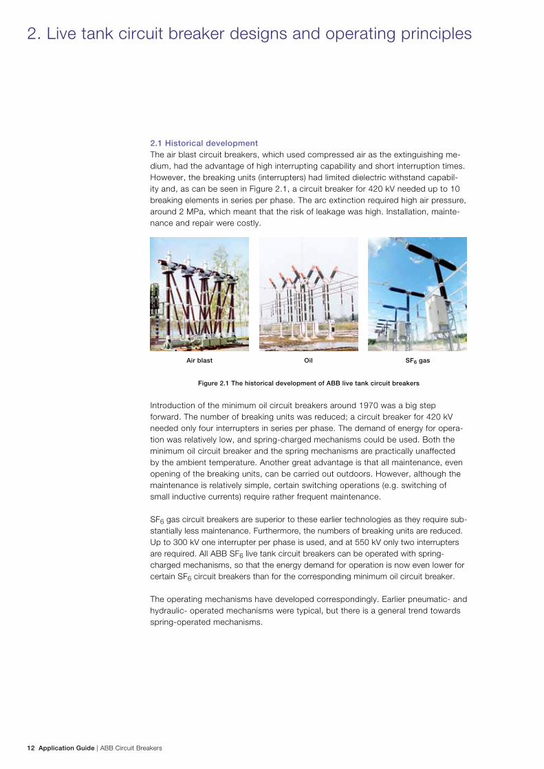
2.1 Historical developmentThe air blast circuit breakers, which used compressed air as the extinguishing me-dium, had the advantage of high interrupting capability and short interruption times. However, the breaking units (interrupters) had limited dielectric withstand capabil-ity and, as can be seen in Figure 2.1, a circuit breaker for 420 kV needed up to 10 breaking elements in series per phase. The arc extinction required high air pressure, around 2 MPa, which meant that the risk of leakage was high. Installation, mainte-nance and repair were costly.
Air blast Oil SF6 gas
Figure 2.1 The historical development of ABB live tank circuit breakers
Introduction of the minimum oil circuit breakers around 1970 was a big step forward. The number of breaking units was reduced; a circuit breaker for 420 kV needed only four interrupters in series per phase. The demand of energy for opera-tion was relatively low, and spring-charged mechanisms could be used. Both the minimum oil circuit breaker and the spring mechanisms are practically unaffected by the ambient temperature. Another great advantage is that all maintenance, even opening of the breaking units, can be carried out outdoors. However, although the maintenance is relatively simple, certain switching operations (e.g. switching of small inductive currents) require rather frequent maintenance.
SF6 gas circuit breakers are superior to these earlier technologies as they require sub-stantially less maintenance. Furthermore, the numbers of breaking units are reduced. Up to 300 kV one interrupter per phase is used, and at 550 kV only two interrupters are required. All ABB SF6 live tank circuit breakers can be operated with spring-charged mechanisms, so that the energy demand for operation is now even lower for certain SF6 circuit breakers than for the corresponding minimum oil circuit breaker.
The operating mechanisms have developed correspondingly. Earlier pneumatic- and hydraulic- operated mechanisms were typical, but there is a general trend towards spring-operated mechanisms.
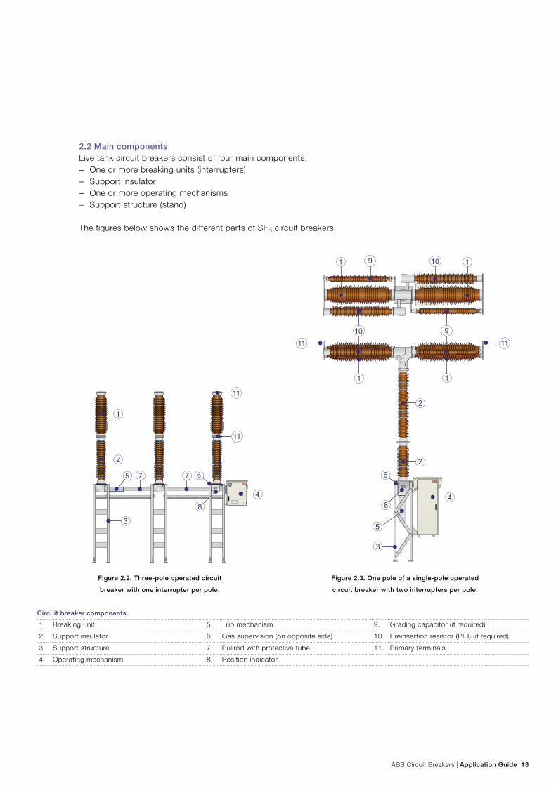
ABB Circuit Breakers | Application Guide 13
2.2 Main componentsLive tank circuit breakers consist of four main components:
− One or more breaking units (interrupters) − Support insulator − One or more operating mechanisms − Support structure (stand)
The figures below shows the different parts of SF6 circuit breakers.
Figure 2.2. Three-pole operated circuit
breaker with one interrupter per pole.
Figure 2.3. One pole of a single-pole operated
circuit breaker with two interrupters per pole.
Circuit breaker components
1. Breaking unit 5. Trip mechanism 9. Grading capacitor (if required)
2. Support insulator 6. Gas supervision (on opposite side) 10. Preinsertion resistor (PIR) (if required)
3. Support structure 7. Pullrod with protective tube 11. Primary terminals
4. Operating mechanism 8. Position indicator
14 Application Guide | ABB Circuit Breakers
2.2.1 Breaking unitThe insulating housing is made of porcelain or composite material and is filled with pressurized SF6 gas. The breaking unit is subjected to potential, i.e. it is “live”, hence the term “live tank” circuit breaker.
One circuit breaker pole can even consist of two or more breaking units in series. The number of breaking units is dependent on the system voltage and the require-ments on interrupting capability.
The function of the extinction chamber is described under 2.4.2 “Principles of arc extinction.”
2.2.2 Support insulator The main function of the support insulator is to ensure sufficient insulation from the HV-terminals and the breaking unit(s) to ground. The support insulator is a hollow housing made of porcelain or composite material and contains SF6 gas at the same pressure as the gas in the breaking units; the support insulator and the breaking unit(s) have a common gas atmosphere.
The insulated pull rod, (also called operating insulator) which is part of the link-age system between the operating mechanism and the main contacts, is mounted inside the support insulator.
2.2.3 Operating mechanismThe operating mechanism, together with the trip spring, stores the necessary en-ergy for the closing and opening operation of the circuit breaker. Located at ground potential, the operating mechanism also includes secondary wiring, which acts as an interface to a network’s control and protection system.
2.2.4 Support structureThere are two versions of support structures (or support stand) for live tank circuit breakers:
− Three-column supports, i.e. each circuit breaker pole is mounted on its individual support.
− Pole-beam support, i.e. the three poles mounted on one common beam with two support legs.
The supports are usually made of hot-dip galvanized steel.
2. Live tank circuit breaker designs and operating principles
ABB Circuit Breakers | Application Guide 15
2.3 Additional components
2.3.1 Grading capacitorsFor circuit breakers with two or more breaking units in series, the voltage (rated voltage as well as transient switching and lightning overvoltages) will usually not be evenly distributed across the interrupters. In order to avoid high voltage stresses across one of the breaking units, capacitors are often mounted in parallel with the interrupters. The capacitance is usually on the order of 900 – 1,600 pF per breaking unit.
The performance of circuit breakers is gradually improving, and nowadays grad-ing capacitors are generally not needed at rated voltages up to 420 kV. The ABB circuit breaker of the HPL type has recently been verified by type tests to handle 550 kV without grading capacitors. This offers several advantages: easier trans-port and installation; lower mass, which improves the seismic withstand capabil-ity; decreases in leakage currents; and a reduced risk of ferroresonance in nearby inductive voltage transformers.
2.3.2 Preinsertion resistorsPreinsertion resistors on line circuit breakers are used occasionally at rated volt-ages 362 – 420 kV and more often at 550 – 800 kV. Their purpose is to reduce the voltage transients generated when a no-load transmission line is energized, or re-energized after a line fault.
The resistors are operated by the same operating mechanism as the main contacts.
Preinsertion resistors were previously sometimes used on circuit breakers for capacitor banks, reactor banks and transformers. For these applications, however, controlled switching is now widely used as a powerful means to reduce the switch-ing transients. Modern SF6 circuit breakers also have better switching properties than old circuit breaker types. This has generally made preinsertion resistors super-fluous for these applications.
New technologies may also eliminate the need for preinsertion resistors for line circuit breakers. In many cases controlled switching can replace the resistors and reduce the voltage transients to the same extent as, or even better than, resistors. See ABB Controlled Switching, Buyer’s and Application Guide.
2.3.3 Cabinets for central controlCircuit breakers for single-pole operation can be provided with cabinets for central control. These are convenient for local three-pole operation.
In some cases one of the operating mechanism cabinets is expanded to handle integration of the functions of the central control cabinet. This solution is sometimes referred to as “Master-slave” or ICC, Integrated Control Cubicle.
16 Application Guide | ABB Circuit Breakers
2.4 SF6 Interrupters
2.4.1 SF6 gasHigh-voltage circuit breakers with SF6 gas as the insulation and quenching medium have been in use throughout the world for more than 30 years. This gas is particu-larly suitable because of its high dielectric strength and thermal conductivity.
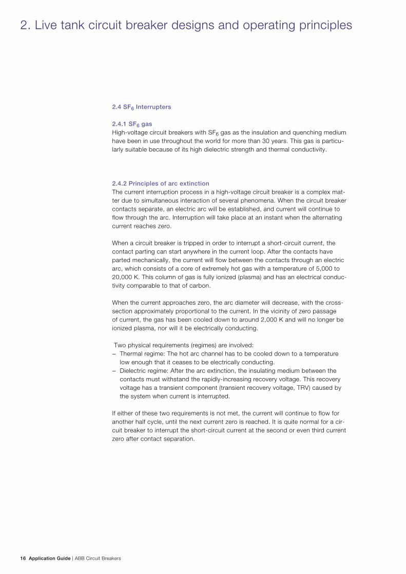
2.4.2 Principles of arc extinctionThe current interruption process in a high-voltage circuit breaker is a complex mat-ter due to simultaneous interaction of several phenomena. When the circuit breaker contacts separate, an electric arc will be established, and current will continue to flow through the arc. Interruption will take place at an instant when the alternating current reaches zero.
When a circuit breaker is tripped in order to interrupt a short-circuit current, the contact parting can start anywhere in the current loop. After the contacts have parted mechanically, the current will flow between the contacts through an electric arc, which consists of a core of extremely hot gas with a temperature of 5,000 to 20,000 K. This column of gas is fully ionized (plasma) and has an electrical conduc-tivity comparable to that of carbon.
When the current approaches zero, the arc diameter will decrease, with the cross-section approximately proportional to the current. In the vicinity of zero passage of current, the gas has been cooled down to around 2,000 K and will no longer be ionized plasma, nor will it be electrically conducting.
Two physical requirements (regimes) are involved: − Thermal regime: The hot arc channel has to be cooled down to a temperature
low enough that it ceases to be electrically conducting. − Dielectric regime: After the arc extinction, the insulating medium between the
contacts must withstand the rapidly-increasing recovery voltage. This recovery voltage has a transient component (transient recovery voltage, TRV) caused by the system when current is interrupted.
If either of these two requirements is not met, the current will continue to flow for another half cycle, until the next current zero is reached. It is quite normal for a cir-cuit breaker to interrupt the short-circuit current at the second or even third current zero after contact separation.
2. Live tank circuit breaker designs and operating principles
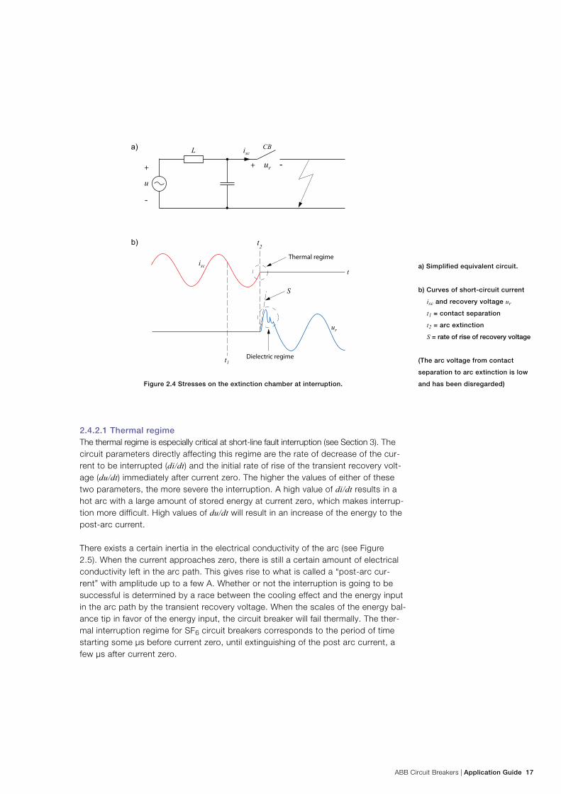
ABB Circuit Breakers | Application Guide 17
Figure 2.4 Stresses on the extinction chamber at interruption.
2.4.2.1 Thermal regimeThe thermal regime is especially critical at short-line fault interruption (see Section 3). The circuit parameters directly affecting this regime are the rate of decrease of the cur-rent to be interrupted (di/dt) and the initial rate of rise of the transient recovery volt-age (du/dt) immediately after current zero. The higher the values of either of these two parameters, the more severe the interruption. A high value of di/dt results in a hot arc with a large amount of stored energy at current zero, which makes interrup-tion more difficult. High values of du/dt will result in an increase of the energy to the post-arc current.
There exists a certain inertia in the electrical conductivity of the arc (see Figure 2.5). When the current approaches zero, there is still a certain amount of electrical conductivity left in the arc path. This gives rise to what is called a “post-arc cur-rent” with amplitude up to a few A. Whether or not the interruption is going to be successful is determined by a race between the cooling effect and the energy input in the arc path by the transient recovery voltage. When the scales of the energy bal-ance tip in favor of the energy input, the circuit breaker will fail thermally. The ther-mal interruption regime for SF6 circuit breakers corresponds to the period of time starting some µs before current zero, until extinguishing of the post arc current, a few µs after current zero.
a) Simplified equivalent circuit.
b) Curves of short-circuit current
isc and recovery voltage ur
t1 = contact separation
t2 = arc extinction
S = rate of rise of recovery voltage
(The arc voltage from contact
separation to arc extinction is low
and has been disregarded)
18 Application Guide | ABB Circuit Breakers
Figure 2.5 Current shape at interruption (the time scale is in the microsecond range).
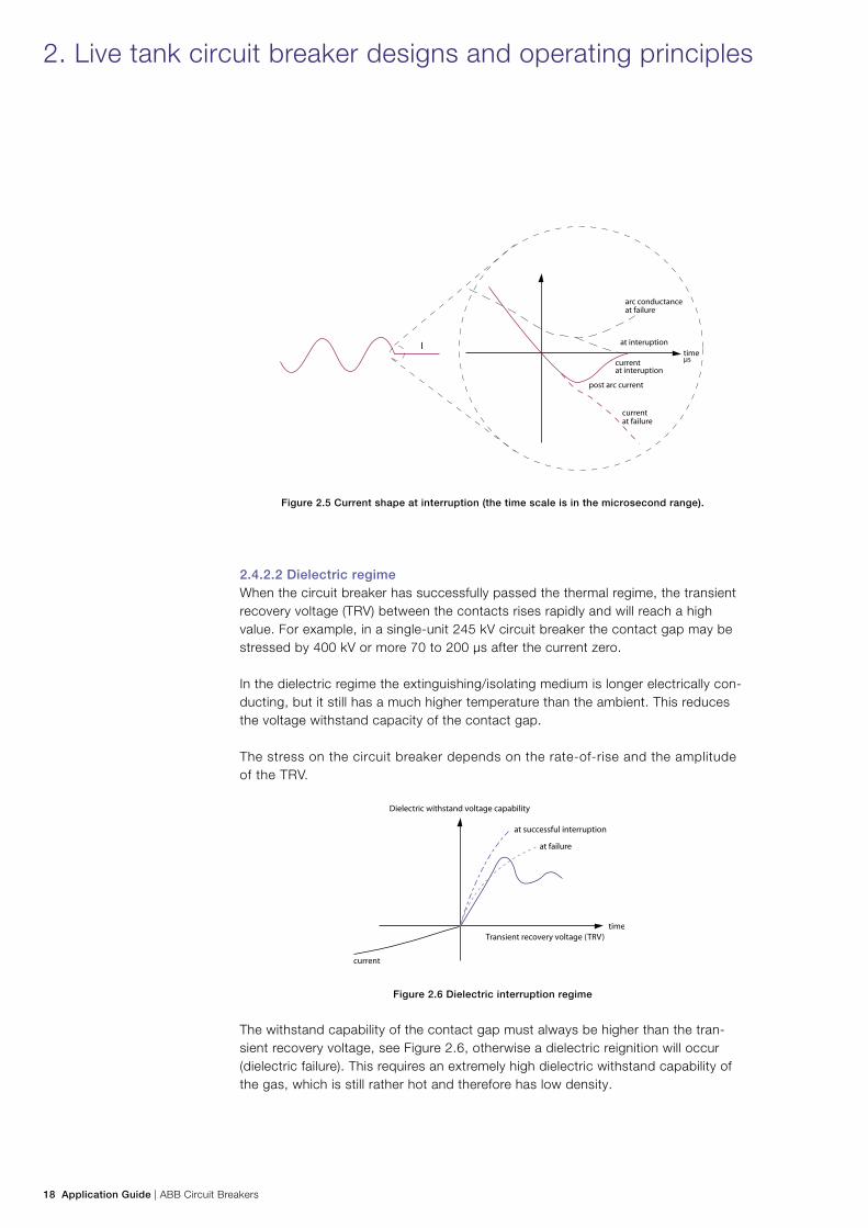
2.4.2.2 Dielectric regimeWhen the circuit breaker has successfully passed the thermal regime, the transient recovery voltage (TRV) between the contacts rises rapidly and will reach a high value. For example, in a single-unit 245 kV circuit breaker the contact gap may be stressed by 400 kV or more 70 to 200 µs after the current zero.
In the dielectric regime the extinguishing/isolating medium is longer electrically con-ducting, but it still has a much higher temperature than the ambient. This reduces the voltage withstand capacity of the contact gap.
The stress on the circuit breaker depends on the rate-of-rise and the amplitude of the TRV.
Figure 2.6 Dielectric interruption regime
The withstand capability of the contact gap must always be higher than the tran-sient recovery voltage, see Figure 2.6, otherwise a dielectric reignition will occur (dielectric failure). This requires an extremely high dielectric withstand capability of the gas, which is still rather hot and therefore has low density.
2. Live tank circuit breaker designs and operating principles
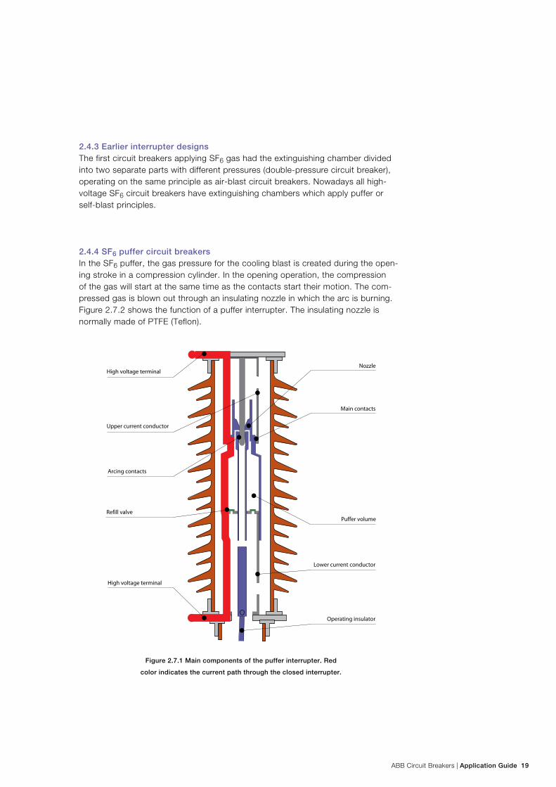
ABB Circuit Breakers | Application Guide 19
2.4.3 Earlier interrupter designsThe first circuit breakers applying SF6 gas had the extinguishing chamber divided into two separate parts with different pressures (double-pressure circuit breaker), operating on the same principle as air-blast circuit breakers. Nowadays all high-voltage SF6 circuit breakers have extinguishing chambers which apply puffer or self-blast principles.
2.4.4 SF6 puffer circuit breakersIn the SF6 puffer, the gas pressure for the cooling blast is created during the open-ing stroke in a compression cylinder. In the opening operation, the compression of the gas will start at the same time as the contacts start their motion. The com-pressed gas is blown out through an insulating nozzle in which the arc is burning. Figure 2.7.2 shows the function of a puffer interrupter. The insulating nozzle is normally made of PTFE (Teflon).
Figure 2.7.1 Main components of the puffer interrupter. Red
color indicates the current path through the closed interrupter.
20 Application Guide | ABB Circuit Breakers
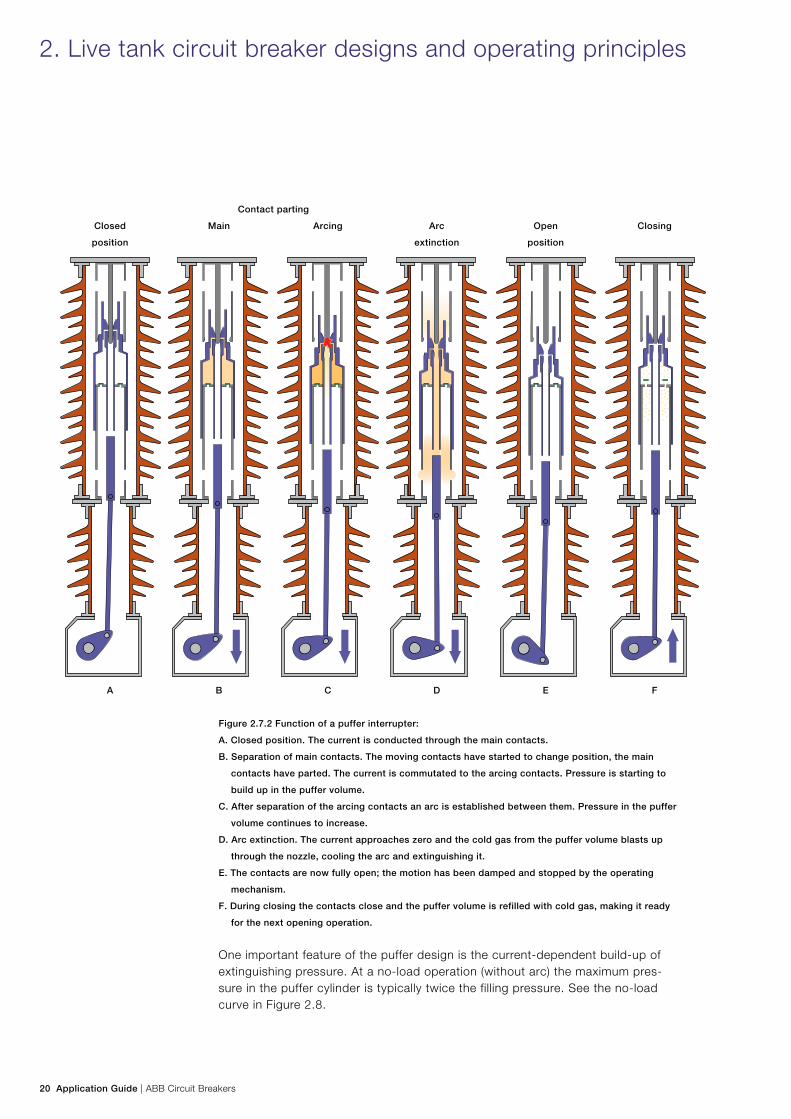
Figure 2.7.2 Function of a puffer interrupter:
A. Closed position. The current is conducted through the main contacts.
B. Separation of main contacts. The moving contacts have started to change position, the main
contacts have parted. The current is commutated to the arcing contacts. Pressure is starting to
build up in the puffer volume.
C. After separation of the arcing contacts an arc is established between them. Pressure in the puffer
volume continues to increase.
D. Arc extinction. The current approaches zero and the cold gas from the puffer volume blasts up
through the nozzle, cooling the arc and extinguishing it.
E. The contacts are now fully open; the motion has been damped and stopped by the operating
mechanism.
F. During closing the contacts close and the puffer volume is refilled with cold gas, making it ready
for the next opening operation.
One important feature of the puffer design is the current-dependent build-up of extinguishing pressure. At a no-load operation (without arc) the maximum pres-sure in the puffer cylinder is typically twice the filling pressure. See the no-load curve in Figure 2.8.
Contact parting
Closed
position
Main Arcing Arc
extinction
Open
position
Closing
A B C D E F
2. Live tank circuit breaker designs and operating principles
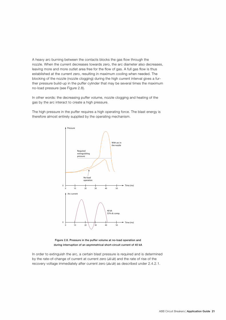
ABB Circuit Breakers | Application Guide 21
A heavy arc burning between the contacts blocks the gas flow through the nozzle. When the current decreases towards zero, the arc diameter also decreases, leaving more and more outlet area free for the flow of gas. A full gas flow is thus established at the current zero, resulting in maximum cooling when needed. The blocking of the nozzle (nozzle clogging) during the high current interval gives a fur-ther pressure build-up in the puffer cylinder that may be several times the maximum no-load pressure (see Figure 2.8).
In other words: the decreasing puffer volume, nozzle clogging and heating of the gas by the arc interact to create a high pressure.
The high pressure in the puffer requires a high operating force. The blast energy is therefore almost entirely supplied by the operating mechanism.
Figure 2.8. Pressure in the puffer volume at no-load operation and
during interruption of an asymmetrical short-circuit current of 40 kA
In order to extinguish the arc, a certain blast pressure is required and is determined by the rate-of-change of current at current zero (di/dt) and the rate of rise of the recovery voltage immediately after current zero (du/dt) as described under 2.4.2.1.
22 Application Guide | ABB Circuit Breakers
2.4.5 SF6 self-blast circuit breakers Service experience has shown that circuit breaker failures due to insufficient inter-rupting capacity are rare. The majority of the failures reported are of a mechanical nature, which is why efforts are made to improve the overall reliability of the op-erating mechanisms. Because of the fact that puffer circuit breakers require high operating energy, the manufacturers were forced to use pneumatic mechanisms, hydraulic mechanisms or high-energy spring mechanisms.
In a normal puffer circuit breaker, the major part of the blast pressure is created with energy from the operating mechanism. The ideal situation would be to let the arc produce the blast pressure. In this way, the operating mechanism only needs to deliver energy necessary for the movement of the contact. However, this ideal situation cannot currently not be reached at higher voltages. Problems will arise when interrupting small currents, since there is only a limited amount of energy available for the pressure rise. For this rea-son a compromise has been reached: a self-blast circuit breaker with pre-compression.
The self-blast principles represented a large step forward on the way to reducing the operating energy.
The self-blast technology has several designations: auto-puffer, arc-assisted circuit breaker, thermal-assisted circuit breaker or simply self-blast circuit breaker.
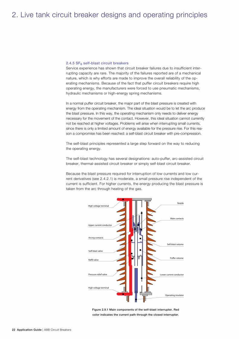
Because the blast pressure required for interruption of low currents and low cur-rent derivatives (see 2.4.2.1) is moderate, a small pressure rise independent of the current is sufficient. For higher currents, the energy producing the blast pressure is taken from the arc through heating of the gas.
Figure 2.9.1 Main components of the self-blast interrupter. Red
color indicates the current path through the closed interrupter.
2. Live tank circuit breaker designs and operating principles
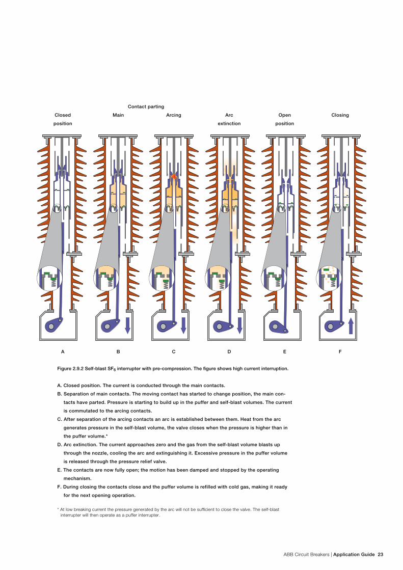
ABB Circuit Breakers | Application Guide 23
Contact parting
Closed
position
Main Arcing Arc
extinction
Open
position
Closing
A B C D E F
Figure 2.9.2 Self-blast SF6 interrupter with pre-compression. The figure shows high current interruption.
A. Closed position. The current is conducted through the main contacts.
B. Separation of main contacts. The moving contact has started to change position, the main con-
tacts have parted. Pressure is starting to build up in the puffer and self-blast volumes. The current
is commutated to the arcing contacts.
C. After separation of the arcing contacts an arc is established between them. Heat from the arc
generates pressure in the self-blast volume, the valve closes when the pressure is higher than in
the puffer volume.*
D. Arc extinction. The current approaches zero and the gas from the self-blast volume blasts up
through the nozzle, cooling the arc and extinguishing it. Excessive pressure in the puffer volume
is released through the pressure relief valve.
E. The contacts are now fully open; the motion has been damped and stopped by the operating
mechanism.
F. During closing the contacts close and the puffer volume is refilled with cold gas, making it ready
for the next opening operation.
* At low breaking current the pressure generated by the arc will not be sufficient to close the valve. The self-blast interrupter will then operate as a puffer interrupter.
24 Application Guide | ABB Circuit Breakers
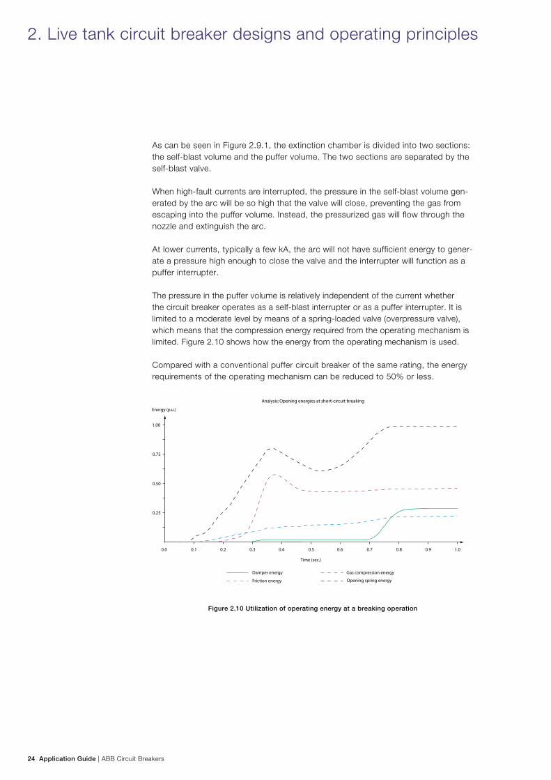
As can be seen in Figure 2.9.1, the extinction chamber is divided into two sections: the self-blast volume and the puffer volume. The two sections are separated by the self-blast valve.
When high-fault currents are interrupted, the pressure in the self-blast volume gen-erated by the arc will be so high that the valve will close, preventing the gas from escaping into the puffer volume. Instead, the pressurized gas will flow through the nozzle and extinguish the arc.
At lower currents, typically a few kA, the arc will not have sufficient energy to gener-ate a pressure high enough to close the valve and the interrupter will function as a puffer interrupter.
The pressure in the puffer volume is relatively independent of the current whether the circuit breaker operates as a self-blast interrupter or as a puffer interrupter. It is limited to a moderate level by means of a spring-loaded valve (overpressure valve), which means that the compression energy required from the operating mechanism is limited. Figure 2.10 shows how the energy from the operating mechanism is used.
Compared with a conventional puffer circuit breaker of the same rating, the energy requirements of the operating mechanism can be reduced to 50% or less.
Figure 2.10 Utilization of operating energy at a breaking operation
2. Live tank circuit breaker designs and operating principles
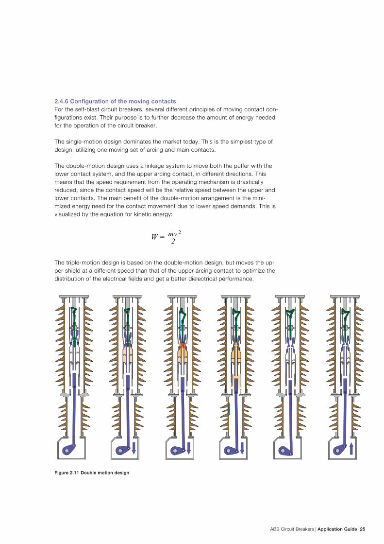
ABB Circuit Breakers | Application Guide 25
2.4.6 Configuration of the moving contactsFor the self-blast circuit breakers, several different principles of moving contact con-figurations exist. Their purpose is to further decrease the amount of energy needed for the operation of the circuit breaker.
The single-motion design dominates the market today. This is the simplest type of design, utilizing one moving set of arcing and main contacts.
The double-motion design uses a linkage system to move both the puffer with the lower contact system, and the upper arcing contact, in different directions. This means that the speed requirement from the operating mechanism is drastically reduced, since the contact speed will be the relative speed between the upper and lower contacts. The main benefit of the double-motion arrangement is the mini-mized energy need for the contact movement due to lower speed demands. This is visualized by the equation for kinetic energy:
The triple-motion design is based on the double-motion design, but moves the up-per shield at a different speed than that of the upper arcing contact to optimize the distribution of the electrical fields and get a better dielectrical performance.
Figure 2.11 Double motion design
26 Application Guide | ABB Circuit Breakers
2.5 Operating mechanisms
2.5.1 General The main requirement of the operating mechanism is to open and close the con-tacts of the circuit breaker within a specified time. The operating mechanism shall provide the following consecutive functions:
− Charging and storing of energy − Release of energy − Transmission of energy − Operation of the contacts
In addition, an operating mechanism shall provide control and signaling interface to a network’s control and protection system.
Figures 2.2 and 2.3 show the location of the operating mechanism.
A requirement common to most circuit breakers, regardless of the type of operating mechanisms, is to carry out an open-close-open (O - 0.3 s - CO) sequence with no external power supply to the operating mechanism. The circuit breaker shall, after a closing operation, always be able to trip immediately without intentional time delay.
For circuit breakers intended for rapid auto-reclosing, the operating duty cycle in accordance with IEC 62271-100 is:
O - 0.3 s - CO - 3 min - CO
The time of 3 min is the time needed for the operating mechanism to restore its power after a O - 0.3 s - CO. Modern spring and hydraulic operating mechanisms do not need 3 min to restore their power, as an alternative IEC specifies that the time val-ues 15 s. or 1 min. can also be used. The dead time of 0.3 s is based on the recovery time of the air surrounding an external arc in the system (i.e. a short-circuit).
Sometimes the operating sequence CO - 15 s - CO is specified.
2. Live tank circuit breaker designs and operating principles
ABB Circuit Breakers | Application Guide 27
2.5.2 Spring-operated mechanismIn the spring mechanism, the energy for open and close operation is stored in springs. When the mechanism’s control system receives an open or close command, the energy stored in the spring will be released and transmitted through a system of levers and links and the contacts will move to the open or closed position.
In most designs the closing spring has two tasks: to close the contacts, and at the same time to charge the opening spring (or springs). Thus the criteria stated above are fulfilled; the circuit breaker in closed position is always ready to trip.
After the O - 0.3 s - CO operation, the closing spring will be recharged by an elec-tric motor, a procedure that lasts 10-20 seconds. The circuit breaker will then be ready for another CO operation.
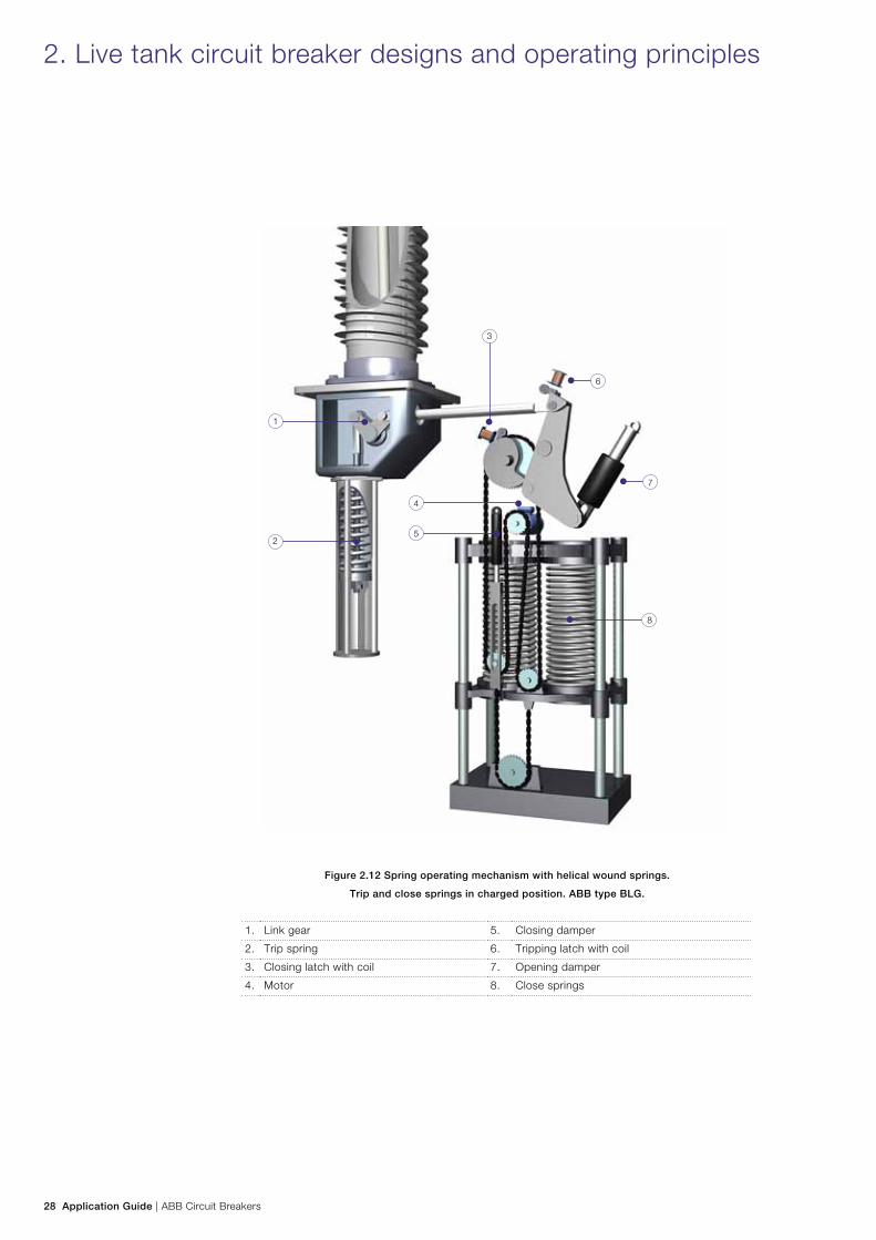
One example of a spring mechanism is shown in Figure 2.12. This type of mecha-nism has a set of parallel helical wound springs with linear motion. The electric motor charges the springs via an endless chain. When the closing latch is released, the energy stored in the springs is transmitted via a rotating cam disc and a system of levers and links to the circuit breaker pole or poles. The trip spring is in this case located outside the operating mechanism.
Instead of helical springs, clock springs may be applied. The function is the same as for the helical springs described above. Figure 2.13 shows a system with clock spring for closing operation.
The advantage of the spring-operated mechanism is that the system is purely mechanical; there is no risk of leakage of oil or gas, which could jeopardize the reli-ability. A well-balanced latching system provides stable operating times.
Furthermore, the spring system is less sensitive to variations in temperature than pneumatic or hydraulic mechanisms are. This ensures stability even at extreme temperatures.
The spring mechanism has fewer components than hydraulic and pneumatic mechanisms, which improves its reliability.
28 Application Guide | ABB Circuit Breakers
Figure 2.12 Spring operating mechanism with helical wound springs.
Trip and close springs in charged position. ABB type BLG.
1. Link gear 5. Closing damper
2. Trip spring 6. Tripping latch with coil
3. Closing latch with coil 7. Opening damper
4. Motor 8. Close springs
2. Live tank circuit breaker designs and operating principles
1
2
7
6
8
4
5
3
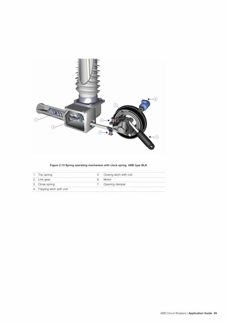
ABB Circuit Breakers | Application Guide 29
Figure 2.13 Spring operating mechanism with clock spring. ABB type BLK.
1. Trip spring 5. Closing latch with coil
2. Link gear 6. Motor
3. Close spring 7. Opening damper
4. Tripping latch with coil
1
5
4
3
2
6
7
30 Application Guide | ABB Circuit Breakers
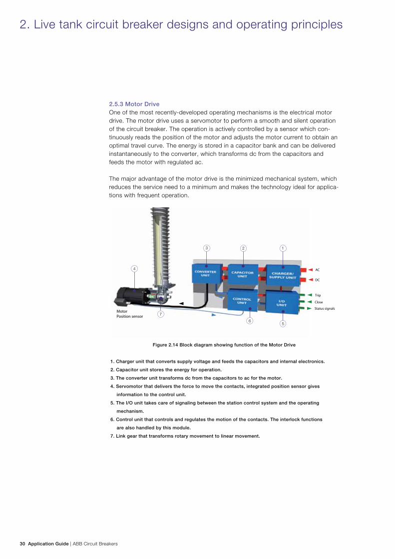
2.5.3 Motor DriveOne of the most recently-developed operating mechanisms is the electrical motor drive. The motor drive uses a servomotor to perform a smooth and silent operation of the circuit breaker. The operation is actively controlled by a sensor which con-tinuously reads the position of the motor and adjusts the motor current to obtain an optimal travel curve. The energy is stored in a capacitor bank and can be delivered instantaneously to the converter, which transforms dc from the capacitors and feeds the motor with regulated ac.
The major advantage of the motor drive is the minimized mechanical system, which reduces the service need to a minimum and makes the technology ideal for applica-tions with frequent operation.
Figure 2.14 Block diagram showing function of the Motor Drive
1. Charger unit that converts supply voltage and feeds the capacitors and internal electronics.
2. Capacitor unit stores the energy for operation.
3. The converter unit transforms dc from the capacitors to ac for the motor.
4. Servomotor that delivers the force to move the contacts, integrated position sensor gives
information to the control unit.
5. The I/O unit takes care of signaling between the station control system and the operating
mechanism.
6. Control unit that controls and regulates the motion of the contacts. The interlock functions
are also handled by this module.
7. Link gear that transforms rotary movement to linear movement.
2. Live tank circuit breaker designs and operating principles
Trip
Close
Status signals
AC
DC
MotorPosition sensor
6
7
5
4
3 2 1
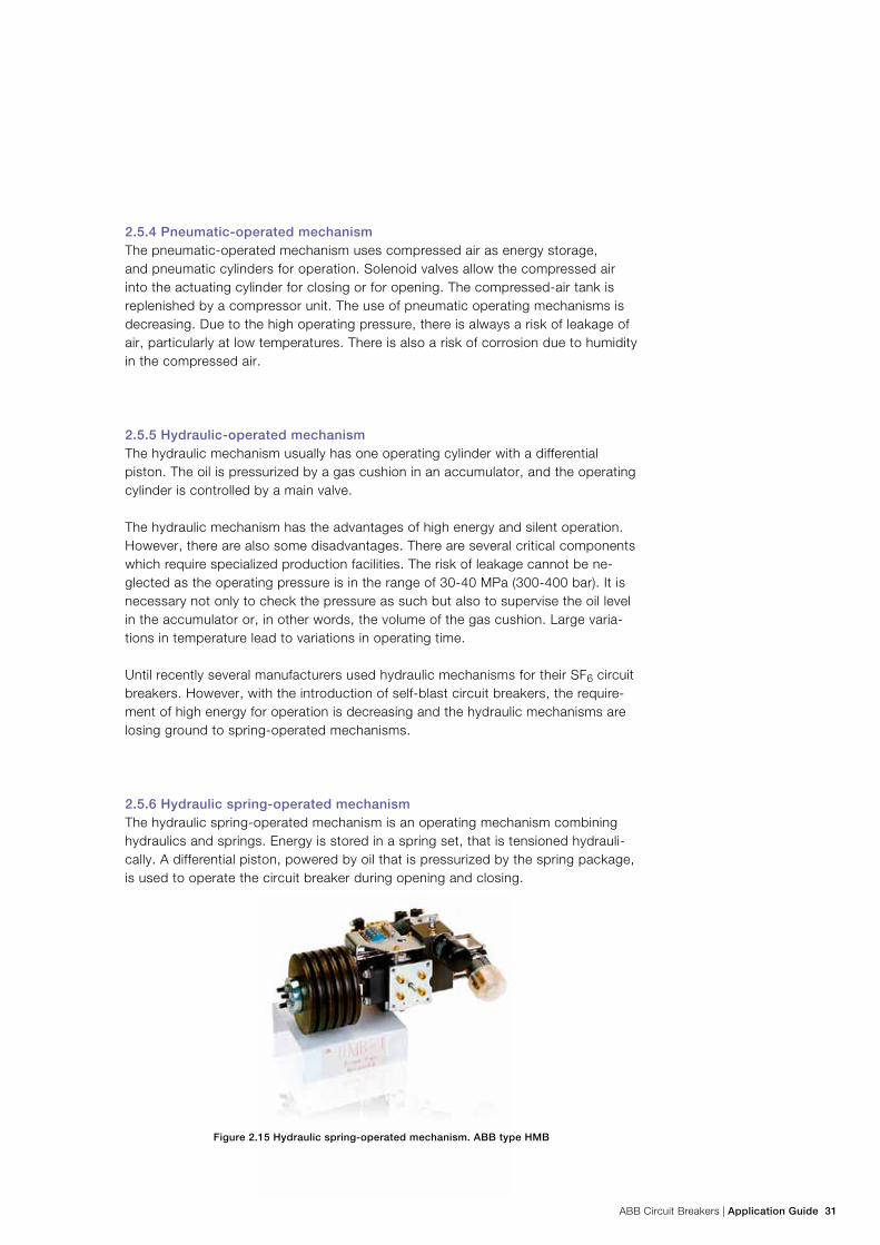
ABB Circuit Breakers | Application Guide 31
2.5.4 Pneumatic-operated mechanismThe pneumatic-operated mechanism uses compressed air as energy storage, and pneumatic cylinders for operation. Solenoid valves allow the compressed air into the actuating cylinder for closing or for opening. The compressed-air tank is replenished by a compressor unit. The use of pneumatic operating mechanisms is decreasing. Due to the high operating pressure, there is always a risk of leakage of air, particularly at low temperatures. There is also a risk of corrosion due to humidity in the compressed air.
2.5.5 Hydraulic-operated mechanism The hydraulic mechanism usually has one operating cylinder with a differential piston. The oil is pressurized by a gas cushion in an accumulator, and the operating cylinder is controlled by a main valve.
The hydraulic mechanism has the advantages of high energy and silent operation. However, there are also some disadvantages. There are several critical components which require specialized production facilities. The risk of leakage cannot be ne-glected as the operating pressure is in the range of 30-40 MPa (300-400 bar). It is necessary not only to check the pressure as such but also to supervise the oil level in the accumulator or, in other words, the volume of the gas cushion. Large varia-tions in temperature lead to variations in operating time.
Until recently several manufacturers used hydraulic mechanisms for their SF6 circuit breakers. However, with the introduction of self-blast circuit breakers, the require-ment of high energy for operation is decreasing and the hydraulic mechanisms are losing ground to spring-operated mechanisms.
2.5.6 Hydraulic spring-operated mechanismThe hydraulic spring-operated mechanism is an operating mechanism combining hydraulics and springs. Energy is stored in a spring set, that is tensioned hydrauli-cally. A differential piston, powered by oil that is pressurized by the spring package, is used to operate the circuit breaker during opening and closing.
Figure 2.15 Hydraulic spring-operated mechanism. ABB type HMB
32 Application Guide | ABB Circuit Breakers
2.5.7 Other types of operating mechanismsIn addition to the types of operating mechanisms mentioned above, there are other variants, e.g. a design which basically applies the same technology as the pneu-matic mechanisms but with SF6 gas instead of air.
Another design is the magnetic actuator mechanism, which is applied only for cer-tain medium-voltage circuit breakers.
2. Live tank circuit breaker designs and operating principles
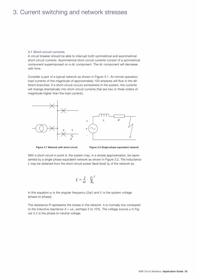
ABB Circuit Breakers | Application Guide 33
3. Current switching and network stresses
3.1 Short-circuit currentsA circuit breaker should be able to interrupt both symmetrical and asymmetrical short-circuit currents. Asymmetrical short-circuit currents consist of a symmetrical component superimposed on a dc component. The dc component will decrease with time.
Consider a part of a typical network as shown in Figure 3.1. At normal operation, load currents of the magnitude of approximately 100 amperes will flow in the dif-ferent branches. If a short-circuit occurs somewhere in the system, the currents will change dramatically into short-circuit currents that are two or three orders of magnitude higher than the load currents.
Figure 3.1 Network with short-circuit Figure 3.2 Single-phase equivalent network
With a short-circuit in point A, the system may, in a simple approximation, be repre-sented by a single-phase equivalent network as shown in Figure 3.2. The inductance L may be obtained from the short-circuit power (fault level) Sk of the network as:
In this equation ω is the angular frequency (2πf ) and U is the system voltage (phase-to-phase).
The resistance R represents the losses in the network. It is normally low compared to the inductive reactance X = ωL, perhaps 5 to 10%. The voltage source u in Fig-ure 3.2 is the phase-to-neutral voltage.
34 Application Guide | ABB Circuit Breakers
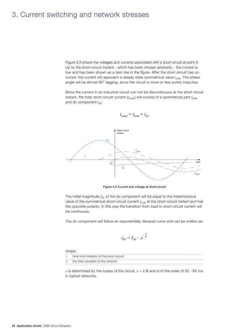
Figure 3.3 shows the voltages and currents associated with a short-circuit at point A. Up to the short-circuit instant - which has been chosen arbitrarily - the current is low and has been shown as a zero line in the figure. After the short-circuit has oc-curred, the current will approach a steady state symmetrical value isym. The phase angle will be almost 90° lagging, since the circuit is more or less purely inductive.
Since the current in an inductive circuit can not be discontinuous at the short-circuit instant, the total short-circuit current (itotal) will consist of a symmetrical part isym and dc component idc:
Figure 3.3 Current and voltage at short-circuit
The initial magnitude Idc of the dc component will be equal to the instantaneous value of the symmetrical short-circuit current isym at the short-circuit instant and has the opposite polarity. In this way the transition from load to short-circuit current will be continuous.
The dc component will follow an exponentially damped curve and can be written as:
where:t time from initiation of the short-circuit
τ the time constant of the network
τ is determined by the losses of the circuit, τ = L/R and is of the order of 20 - 60 ms in typical networks.
3. Current switching and network stresses
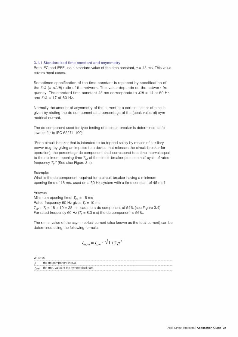
ABB Circuit Breakers | Application Guide 35
3.1.1 Standardized time constant and asymmetryBoth IEC and IEEE use a standard value of the time constant, τ = 45 ms. This value covers most cases.
Sometimes specification of the time constant is replaced by specification of the X/R (= ωL/R) ratio of the network. This value depends on the network fre-quency. The standard time constant 45 ms corresponds to X/R = 14 at 50 Hz, and X/R = 17 at 60 Hz.
Normally the amount of asymmetry of the current at a certain instant of time is given by stating the dc component as a percentage of the (peak value of) sym-metrical current.
The dc component used for type testing of a circuit breaker is determined as fol-lows (refer to IEC 62271-100):
“For a circuit-breaker that is intended to be tripped solely by means of auxiliary power (e.g. by giving an impulse to a device that releases the circuit-breaker for operation), the percentage dc component shall correspond to a time interval equal to the minimum opening time Top of the circuit-breaker plus one half-cycle of rated frequency Tr.” (See also Figure 3.4).
Example: What is the dc component required for a circuit breaker having a minimum opening time of 18 ms, used on a 50 Hz system with a time constant of 45 ms? Answer: Minimum opening time: Top = 18 ms Rated frequency 50 Hz gives Tr = 10 ms Top + Tr = 18 + 10 = 28 ms leads to a dc component of 54% (see Figure 3.4) For rated frequency 60 Hz (Tr = 8.3 ms) the dc component is 56%.
The r.m.s. value of the asymmetrical current (also known as the total current) can be determined using the following formula:
where:p the dc component in p.u.
Isym the rms. value of the symmetrical part
36 Application Guide | ABB Circuit Breakers
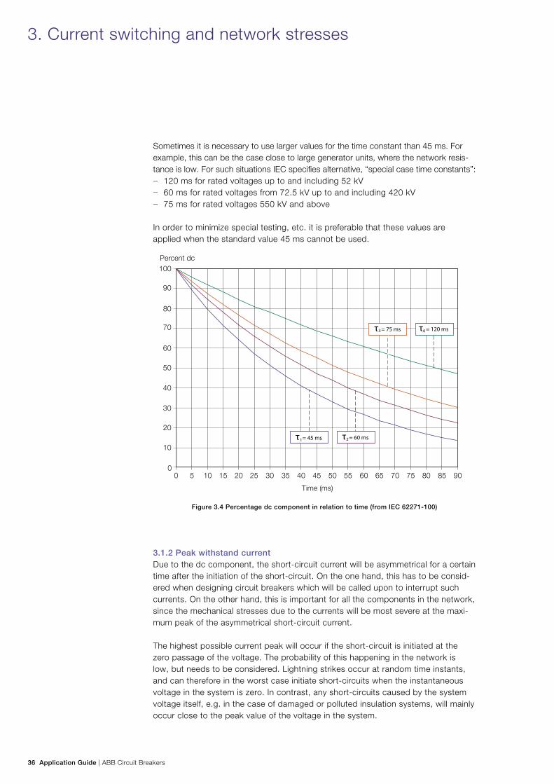
Sometimes it is necessary to use larger values for the time constant than 45 ms. For example, this can be the case close to large generator units, where the network resis-tance is low. For such situations IEC specifies alternative, “special case time constants”:
− 120 ms for rated voltages up to and including 52 kV − 60 ms for rated voltages from 72.5 kV up to and including 420 kV − 75 ms for rated voltages 550 kV and above
In order to minimize special testing, etc. it is preferable that these values are applied when the standard value 45 ms cannot be used.
Figure 3.4 Percentage dc component in relation to time (from IEC 62271-100)
3.1.2 Peak withstand currentDue to the dc component, the short-circuit current will be asymmetrical for a certain time after the initiation of the short-circuit. On the one hand, this has to be consid-ered when designing circuit breakers which will be called upon to interrupt such currents. On the other hand, this is important for all the components in the network, since the mechanical stresses due to the currents will be most severe at the maxi-mum peak of the asymmetrical short-circuit current.
The highest possible current peak will occur if the short-circuit is initiated at the zero passage of the voltage. The probability of this happening in the network is low, but needs to be considered. Lightning strikes occur at random time instants, and can therefore in the worst case initiate short-circuits when the instantaneous voltage in the system is zero. In contrast, any short-circuits caused by the system voltage itself, e.g. in the case of damaged or polluted insulation systems, will mainly occur close to the peak value of the voltage in the system.
3. Current switching and network stresses
10
20
30
40
50
60
70
80
90
100Percent dc
Time (ms)
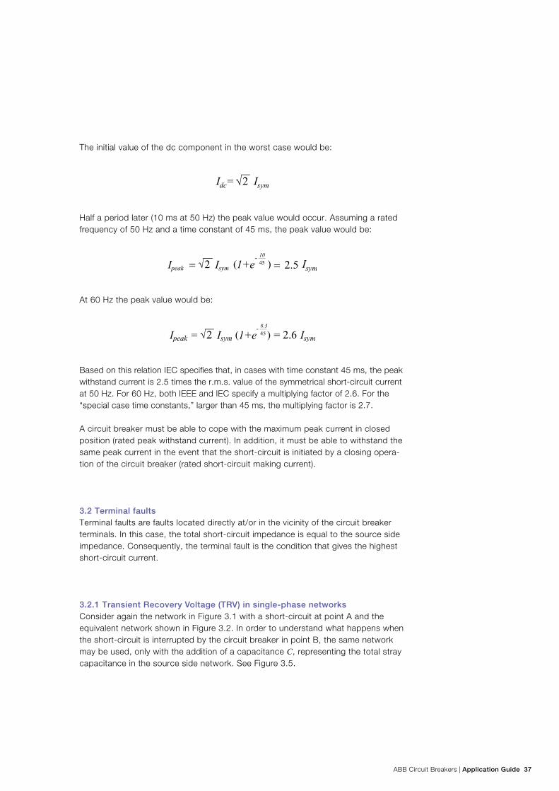
ABB Circuit Breakers | Application Guide 37
The initial value of the dc component in the worst case would be:
Half a period later (10 ms at 50 Hz) the peak value would occur. Assuming a rated frequency of 50 Hz and a time constant of 45 ms, the peak value would be:
At 60 Hz the peak value would be:
Based on this relation IEC specifies that, in cases with time constant 45 ms, the peak withstand current is 2.5 times the r.m.s. value of the symmetrical short-circuit current at 50 Hz. For 60 Hz, both IEEE and IEC specify a multiplying factor of 2.6. For the “special case time constants,” larger than 45 ms, the multiplying factor is 2.7.
A circuit breaker must be able to cope with the maximum peak current in closed position (rated peak withstand current). In addition, it must be able to withstand the same peak current in the event that the short-circuit is initiated by a closing opera-tion of the circuit breaker (rated short-circuit making current).
3.2 Terminal faults Terminal faults are faults located directly at/or in the vicinity of the circuit breaker terminals. In this case, the total short-circuit impedance is equal to the source side impedance. Consequently, the terminal fault is the condition that gives the highest short-circuit current.
3.2.1 Transient Recovery Voltage (TRV) in single-phase networksConsider again the network in Figure 3.1 with a short-circuit at point A and the equivalent network shown in Figure 3.2. In order to understand what happens when the short-circuit is interrupted by the circuit breaker in point B, the same network may be used, only with the addition of a capacitance C, representing the total stray capacitance in the source side network. See Figure 3.5.
38 Application Guide | ABB Circuit Breakers
Figure 3.5 Single-phase equivalent
network for determination of the TRV
Figure 3.6 Current and voltage at interruption
Figure 3.6 shows the current and the voltage at interruption of the current. The circuit breaker will only interrupt the current at a current zero. At this instant the supply voltage u of the network is close to its peak value, since the circuit is almost purely inductive. The voltage across the circuit breaker is low (equal to the arc volt-age) as long as the current has not been interrupted. After interruption, this voltage will approach the value of the supply voltage through a transient oscillation with a frequency determined by L and C of the network. The overshoot will typically be of the order of 40 - 60%. (Had the circuit been entirely without losses, R = 0, the overshoot would have been 100%).
The voltage across the circuit breaker after interruption is called the recovery volt-age. The first oscillatory part of it is referred to as the Transient Recovery Voltage (TRV), while the later part is called power frequency recovery voltage. The power frequency recovery voltage is equal to the open-circuit voltage of the network at the location of the circuit breaker.
Both the Rate of Rise of Recovery Voltage (RRRV) and the peak value of the TRV are important parameters. Together with the magnitude of the current, these param-eters determine the severity of the switching case. The ratio of the peak of the TRV and the peak of the source side voltage is called the amplitude factor.
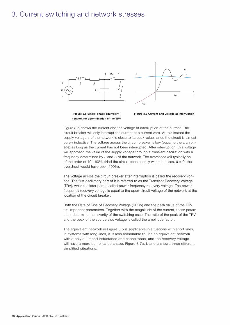
The equivalent network in Figure 3.5 is applicable in situations with short lines. In systems with long lines, it is less reasonable to use an equivalent network with a only a lumped inductance and capacitance, and the recovery voltage will have a more complicated shape. Figure 3.7a, b and c shows three different simplified situations.
3. Current switching and network stresses
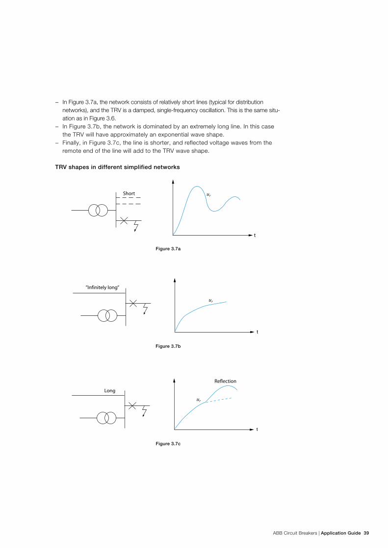
ABB Circuit Breakers | Application Guide 39
− In Figure 3.7a, the network consists of relatively short lines (typical for distribution networks), and the TRV is a damped, single-frequency oscillation. This is the same situ-ation as in Figure 3.6.
− In Figure 3.7b, the network is dominated by an extremely long line. In this case the TRV will have approximately an exponential wave shape.
− Finally, in Figure 3.7c, the line is shorter, and reflected voltage waves from the remote end of the line will add to the TRV wave shape.
TRV shapes in different simplified networks
Figure 3.7a
Figure 3.7b
Figure 3.7c
40 Application Guide | ABB Circuit Breakers
Typical networks with relatively high rated voltage will have TRV wave shapes that are combinations of the single-frequency response of Figure 3.7a and the exponen-tial (with reflection) of Figure 3.7c.
Both IEC and IEEE have the same approach for specification of the standard tran-sient recovery voltages:
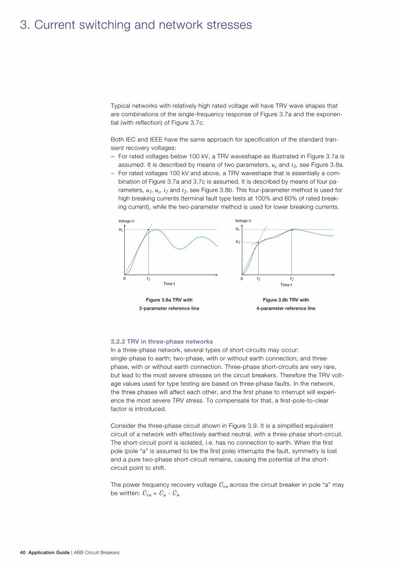
− For rated voltages below 100 kV, a TRV waveshape as illustrated in Figure 3.7a is assumed. It is described by means of two parameters, uc and t3, see Figure 3.8a.
− For rated voltages 100 kV and above, a TRV waveshape that is essentially a com-bination of Figure 3.7a and 3.7c is assumed. It is described by means of four pa-rameters, u1, uc, t1 and t2, see Figure 3.8b. This four-parameter method is used for high breaking currents (terminal fault type tests at 100% and 60% of rated break-ing current), while the two-parameter method is used for lower breaking currents.
Figure 3.8a TRV with
2-parameter reference line
Figure 3.8b TRV with
4-parameter reference line
3.2.2 TRV in three-phase networksIn a three-phase network, several types of short-circuits may occur: single-phase to earth; two-phase, with or without earth connection; and three-phase, with or without earth connection. Three-phase short-circuits are very rare, but lead to the most severe stresses on the circuit breakers. Therefore the TRV volt-age values used for type testing are based on three-phase faults. In the network, the three phases will affect each other, and the first phase to interrupt will experi-ence the most severe TRV stress. To compensate for that, a first-pole-to-clear factor is introduced.
Consider the three-phase circuit shown in Figure 3.9. It is a simplified equivalent circuit of a network with effectively earthed neutral, with a three-phase short-circuit. The short-circuit point is isolated, i.e. has no connection to earth. When the first pole (pole “a” is assumed to be the first pole) interrupts the fault, symmetry is lost and a pure two-phase short-circuit remains, causing the potential of the short-circuit point to shift.
The power frequency recovery voltage Ūra across the circuit breaker in pole “a” may be written: Ūra = Ūa - Ūn
3. Current switching and network stresses
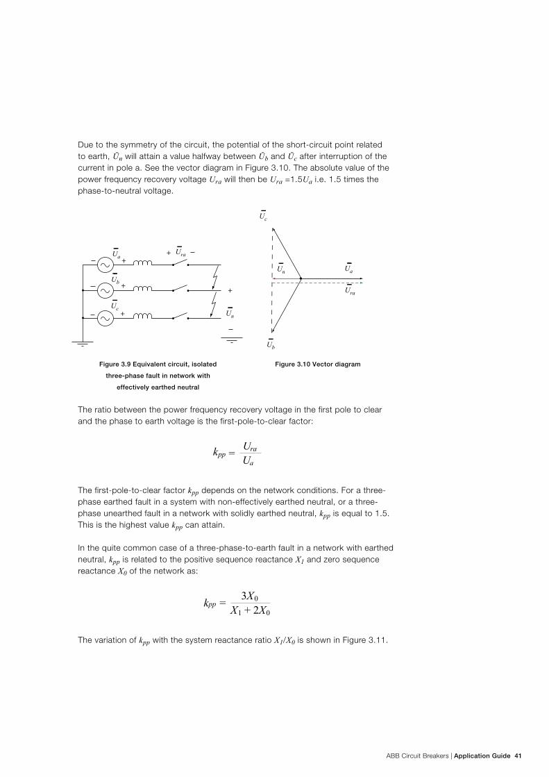
ABB Circuit Breakers | Application Guide 41
Due to the symmetry of the circuit, the potential of the short-circuit point related to earth, Ūn will attain a value halfway between Ūb and Ūc after interruption of the current in pole a. See the vector diagram in Figure 3.10. The absolute value of the power frequency recovery voltage Ura will then be Ura =1.5Ua i.e. 1.5 times the phase-to-neutral voltage.
Figure 3.9 Equivalent circuit, isolated
three-phase fault in network with
effectively earthed neutral
Figure 3.10 Vector diagram
The ratio between the power frequency recovery voltage in the first pole to clear and the phase to earth voltage is the first-pole-to-clear factor:
The first-pole-to-clear factor kpp depends on the network conditions. For a three-phase earthed fault in a system with non-effectively earthed neutral, or a three-phase unearthed fault in a network with solidly earthed neutral, kpp is equal to 1.5. This is the highest value kpp can attain.
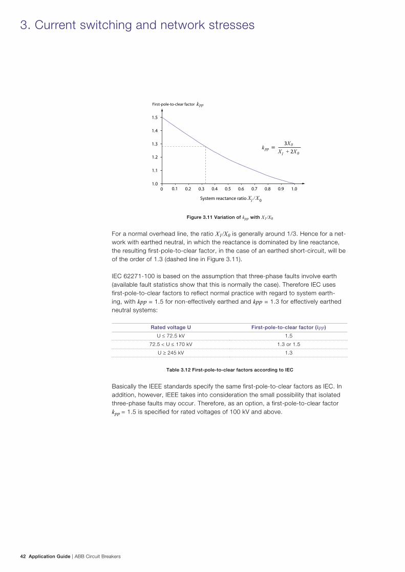
In the quite common case of a three-phase-to-earth fault in a network with earthed neutral, kpp is related to the positive sequence reactance X1 and zero sequence reactance X0 of the network as:
The variation of kpp with the system reactance ratio X1/X0 is shown in Figure 3.11.
42 Application Guide | ABB Circuit Breakers
Figure 3.11 Variation of kpp with X1/X0
For a normal overhead line, the ratio X1/X0 is generally around 1/3. Hence for a net-work with earthed neutral, in which the reactance is dominated by line reactance, the resulting first-pole-to-clear factor, in the case of an earthed short-circuit, will be of the order of 1.3 (dashed line in Figure 3.11).
IEC 62271-100 is based on the assumption that three-phase faults involve earth (available fault statistics show that this is normally the case). Therefore IEC uses first-pole-to-clear factors to reflect normal practice with regard to system earth-ing, with kpp = 1.5 for non-effectively earthed and kpp = 1.3 for effectively earthed neutral systems:
Rated voltage U First-pole-to-clear factor (kpp)
U ≤ 72.5 kV 1.5
72.5 < U ≤ 170 kV 1.3 or 1.5
U ≥ 245 kV 1.3
Table 3.12 First-pole-to-clear factors according to IEC
Basically the IEEE standards specify the same first-pole-to-clear factors as IEC. In addition, however, IEEE takes into consideration the small possibility that isolated three-phase faults may occur. Therefore, as an option, a first-pole-to-clear factor kpp = 1.5 is specified for rated voltages of 100 kV and above.
3. Current switching and network stresses
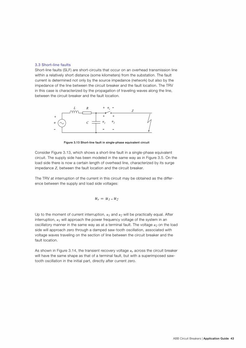
ABB Circuit Breakers | Application Guide 43
3.3 Short-line faultsShort-line faults (SLF) are short-circuits that occur on an overhead transmission line within a relatively short distance (some kilometers) from the substation. The fault current is determined not only by the source impedance (network) but also by the impedance of the line between the circuit breaker and the fault location. The TRV in this case is characterized by the propagation of traveling waves along the line, between the circuit breaker and the fault location.
Figure 3.13 Short-line fault in single-phase equivalent circuit
Consider Figure 3.13, which shows a short-line fault in a single-phase equivalent circuit. The supply side has been modeled in the same way as in Figure 3.5. On the load side there is now a certain length of overhead line, characterized by its surge impedance Z, between the fault location and the circuit breaker.
The TRV at interruption of the current in this circuit may be obtained as the differ-ence between the supply and load side voltages:
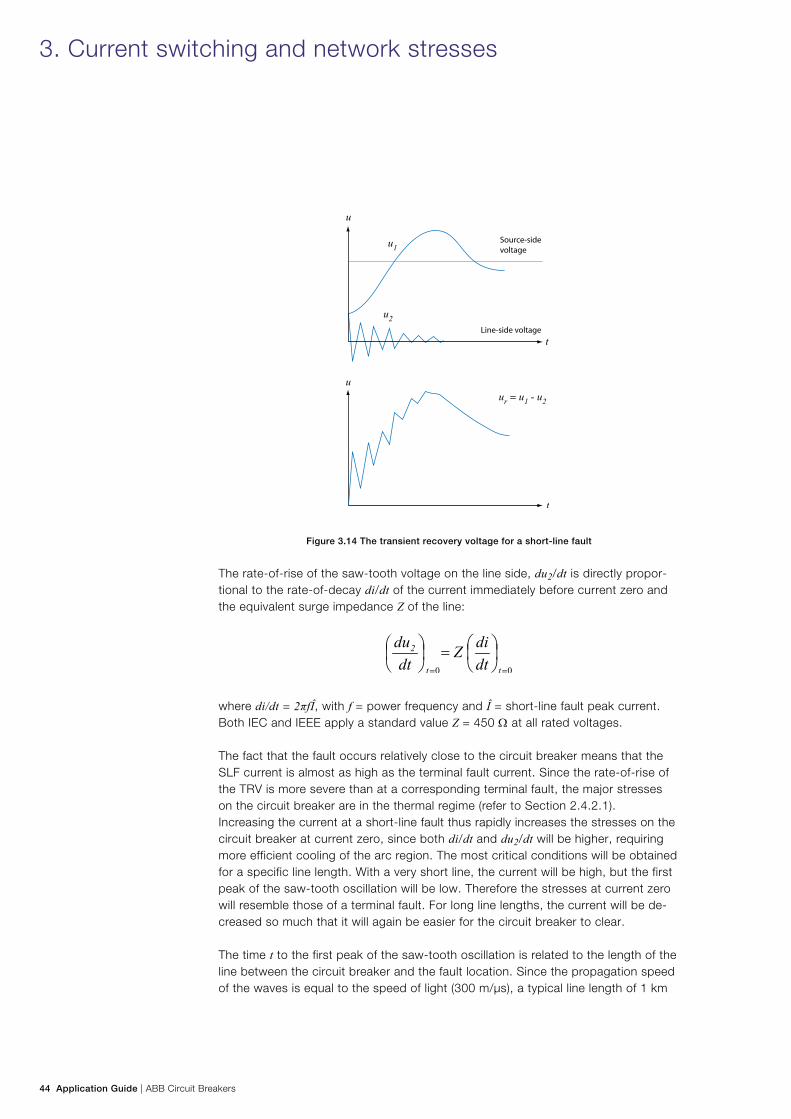
Up to the moment of current interruption, u1 and u2 will be practically equal. After interruption, u1 will approach the power frequency voltage of the system in an oscillatory manner in the same way as at a terminal fault. The voltage u2 on the load side will approach zero through a damped saw-tooth oscillation, associated with voltage waves traveling on the section of line between the circuit breaker and the fault location.
As shown in Figure 3.14, the transient recovery voltage ur across the circuit breaker will have the same shape as that of a terminal fault, but with a superimposed saw-tooth oscillation in the initial part, directly after current zero.
44 Application Guide | ABB Circuit Breakers
Figure 3.14 The transient recovery voltage for a short-line fault
The rate-of-rise of the saw-tooth voltage on the line side, du2/dt is directly propor-tional to the rate-of-decay di/dt of the current immediately before current zero and the equivalent surge impedance Z of the line:
where di/dt = 2πfÎ, with f = power frequency and Î = short-line fault peak current. Both IEC and IEEE apply a standard value Z = 450 Ω at all rated voltages.
The fact that the fault occurs relatively close to the circuit breaker means that the SLF current is almost as high as the terminal fault current. Since the rate-of-rise of the TRV is more severe than at a corresponding terminal fault, the major stresses on the circuit breaker are in the thermal regime (refer to Section 2.4.2.1). Increasing the current at a short-line fault thus rapidly increases the stresses on the circuit breaker at current zero, since both di/dt and du2/dt will be higher, requiring more efficient cooling of the arc region. The most critical conditions will be obtained for a specific line length. With a very short line, the current will be high, but the first peak of the saw-tooth oscillation will be low. Therefore the stresses at current zero will resemble those of a terminal fault. For long line lengths, the current will be de-creased so much that it will again be easier for the circuit breaker to clear.
The time t to the first peak of the saw-tooth oscillation is related to the length of the line between the circuit breaker and the fault location. Since the propagation speed of the waves is equal to the speed of light (300 m/µs), a typical line length of 1 km
3. Current switching and network stresses
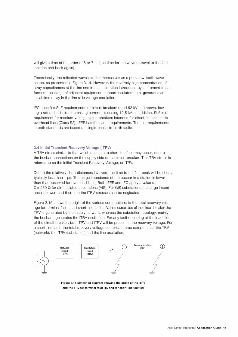
ABB Circuit Breakers | Application Guide 45
will give a time of the order of 6 or 7 µs (the time for the wave to travel to the fault location and back again).
Theoretically, the reflected waves exhibit themselves as a pure saw-tooth wave shape, as presented in Figure 3.14. However, the relatively high concentration of stray capacitances at the line end in the substation introduced by instrument trans-formers, bushings of adjacent equipment, support insulators, etc. generates an initial time delay in the line side voltage oscillation.
IEC specifies SLF requirements for circuit breakers rated 52 kV and above, hav-ing a rated short-circuit breaking current exceeding 12.5 kA. In addition, SLF is a requirement for medium-voltage circuit breakers intended for direct connection to overhead lines (Class S2). IEEE has the same requirements. The test requirements in both standards are based on single-phase-to-earth faults.
3.4 Initial Transient Recovery Voltage (ITRV)A TRV stress similar to that which occurs at a short-line fault may occur, due to the busbar connections on the supply side of the circuit breaker. This TRV stress is referred to as the Initial Transient Recovery Voltage, or ITRV.
Due to the relatively short distances involved, the time to the first peak will be short, typically less than 1 µs. The surge impedance of the busbar in a station is lower than that observed for overhead lines. Both IEEE and IEC apply a value of Z = 260 Ω for air-insulated substations (AIS). For GIS substations the surge imped-ance is lower, and therefore the ITRV stresses can be neglected.
Figure 3.15 shows the origin of the various contributions to the total recovery volt-age for terminal faults and short-line faults. At the source side of the circuit breaker the TRV is generated by the supply network, whereas the substation topology, mainly the busbars, generates the ITRV oscillation. For any fault occurring at the load side of the circuit breaker, both TRV and ITRV will be present in the recovery voltage. For a short-line fault, the total recovery voltage comprises three components: the TRV (network), the ITRV (substation) and the line oscillation.
Figure 3.15 Simplified diagram showing the origin of the ITRV
and the TRV for terminal fault (1), and for short-line fault (2)
46 Application Guide | ABB Circuit Breakers
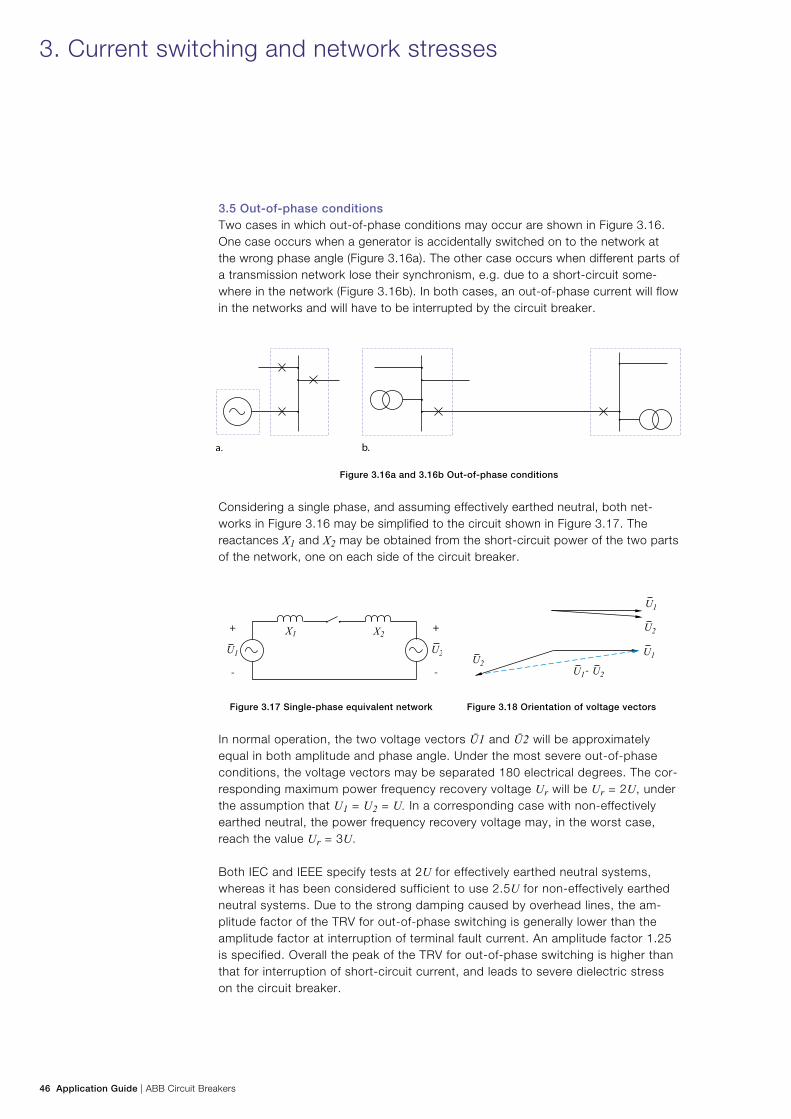
3.5 Out-of-phase conditionsTwo cases in which out-of-phase conditions may occur are shown in Figure 3.16. One case occurs when a generator is accidentally switched on to the network at the wrong phase angle (Figure 3.16a). The other case occurs when different parts of a transmission network lose their synchronism, e.g. due to a short-circuit some-where in the network (Figure 3.16b). In both cases, an out-of-phase current will flow in the networks and will have to be interrupted by the circuit breaker.
Figure 3.16a and 3.16b Out-of-phase conditions
Considering a single phase, and assuming effectively earthed neutral, both net-works in Figure 3.16 may be simplified to the circuit shown in Figure 3.17. The reactances X1 and X2 may be obtained from the short-circuit power of the two parts of the network, one on each side of the circuit breaker.
Figure 3.17 Single-phase equivalent network Figure 3.18 Orientation of voltage vectors
In normal operation, the two voltage vectors Ū1 and Ū2 will be approximately equal in both amplitude and phase angle. Under the most severe out-of-phase conditions, the voltage vectors may be separated 180 electrical degrees. The cor-responding maximum power frequency recovery voltage Ur will be Ur = 2U, under the assumption that U1 = U2 = U. In a corresponding case with non-effectively earthed neutral, the power frequency recovery voltage may, in the worst case, reach the value Ur = 3U.
Both IEC and IEEE specify tests at 2U for effectively earthed neutral systems, whereas it has been considered sufficient to use 2.5U for non-effectively earthed neutral systems. Due to the strong damping caused by overhead lines, the am-plitude factor of the TRV for out-of-phase switching is generally lower than the amplitude factor at interruption of terminal fault current. An amplitude factor 1.25 is specified. Overall the peak of the TRV for out-of-phase switching is higher than that for interruption of short-circuit current, and leads to severe dielectric stress on the circuit breaker.
3. Current switching and network stresses
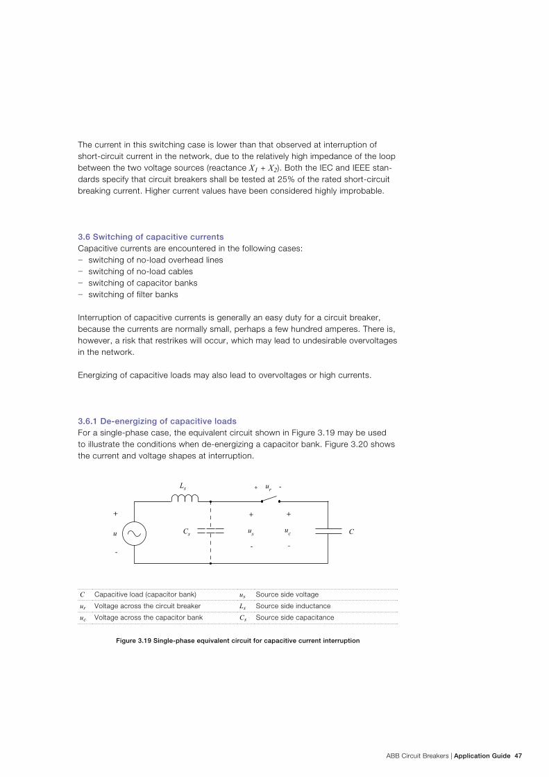
ABB Circuit Breakers | Application Guide 47
The current in this switching case is lower than that observed at interruption of short-circuit current in the network, due to the relatively high impedance of the loop between the two voltage sources (reactance X1 + X2). Both the IEC and IEEE stan-dards specify that circuit breakers shall be tested at 25% of the rated short-circuit breaking current. Higher current values have been considered highly improbable.
3.6 Switching of capacitive currentsCapacitive currents are encountered in the following cases:
− switching of no-load overhead lines − switching of no-load cables − switching of capacitor banks − switching of filter banks
Interruption of capacitive currents is generally an easy duty for a circuit breaker, because the currents are normally small, perhaps a few hundred amperes. There is, however, a risk that restrikes will occur, which may lead to undesirable overvoltages in the network.
Energizing of capacitive loads may also lead to overvoltages or high currents.
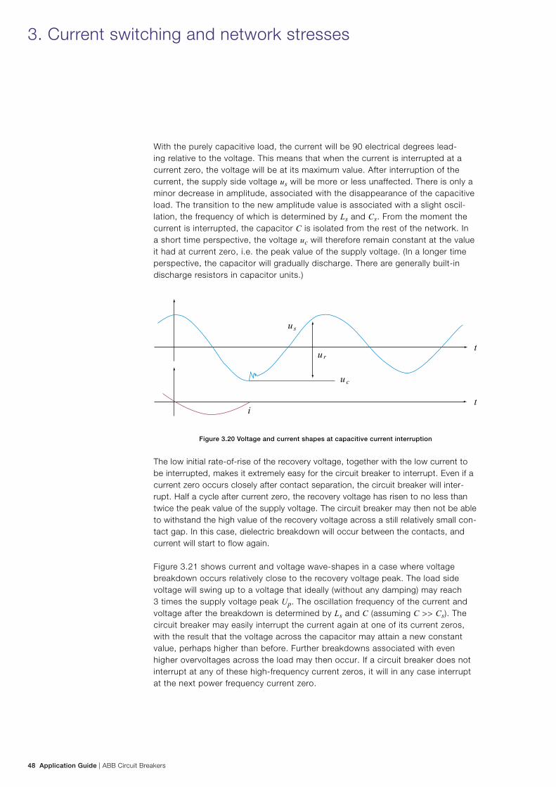
3.6.1 De-energizing of capacitive loadsFor a single-phase case, the equivalent circuit shown in Figure 3.19 may be used to illustrate the conditions when de-energizing a capacitor bank. Figure 3.20 shows the current and voltage shapes at interruption.
C Capacitive load (capacitor bank) us Source side voltage
ur Voltage across the circuit breaker Ls Source side inductance
uc Voltage across the capacitor bank Cs Source side capacitance
Figure 3.19 Single-phase equivalent circuit for capacitive current interruption
48 Application Guide | ABB Circuit Breakers
With the purely capacitive load, the current will be 90 electrical degrees lead-ing relative to the voltage. This means that when the current is interrupted at a current zero, the voltage will be at its maximum value. After interruption of the current, the supply side voltage us will be more or less unaffected. There is only a minor decrease in amplitude, associated with the disappearance of the capacitive load. The transition to the new amplitude value is associated with a slight oscil-lation, the frequency of which is determined by Ls and Cs. From the moment the current is interrupted, the capacitor C is isolated from the rest of the network. In a short time perspective, the voltage uc will therefore remain constant at the value it had at current zero, i.e. the peak value of the supply voltage. (In a longer time perspective, the capacitor will gradually discharge. There are generally built-in discharge resistors in capacitor units.)
Figure 3.20 Voltage and current shapes at capacitive current interruption
The low initial rate-of-rise of the recovery voltage, together with the low current to be interrupted, makes it extremely easy for the circuit breaker to interrupt. Even if a current zero occurs closely after contact separation, the circuit breaker will inter-rupt. Half a cycle after current zero, the recovery voltage has risen to no less than twice the peak value of the supply voltage. The circuit breaker may then not be able to withstand the high value of the recovery voltage across a still relatively small con-tact gap. In this case, dielectric breakdown will occur between the contacts, and current will start to flow again.
Figure 3.21 shows current and voltage wave-shapes in a case where voltage breakdown occurs relatively close to the recovery voltage peak. The load side voltage will swing up to a voltage that ideally (without any damping) may reach 3 times the supply voltage peak Up. The oscillation frequency of the current and voltage after the breakdown is determined by Ls and C (assuming C >> Cs). The circuit breaker may easily interrupt the current again at one of its current zeros, with the result that the voltage across the capacitor may attain a new constant value, perhaps higher than before. Further breakdowns associated with even higher overvoltages across the load may then occur. If a circuit breaker does not interrupt at any of these high-frequency current zeros, it will in any case interrupt at the next power frequency current zero.
3. Current switching and network stresses
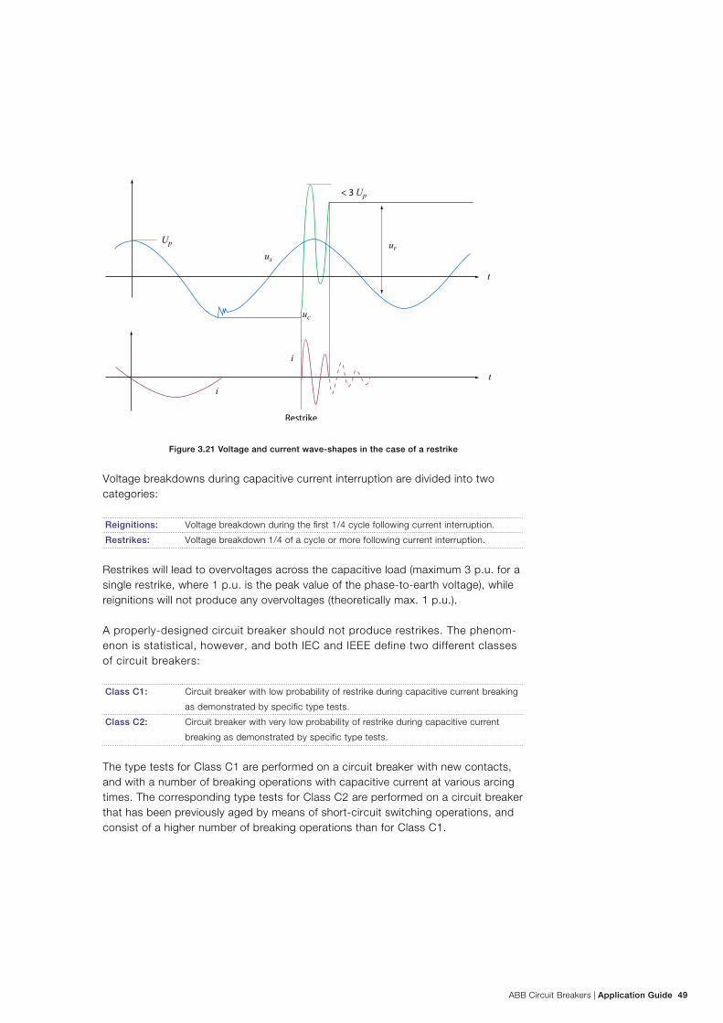
ABB Circuit Breakers | Application Guide 49
Figure 3.21 Voltage and current wave-shapes in the case of a restrike
Voltage breakdowns during capacitive current interruption are divided into two categories:
Reignitions: Voltage breakdown during the first 1/4 cycle following current interruption.
Restrikes: Voltage breakdown 1/4 of a cycle or more following current interruption.
Restrikes will lead to overvoltages across the capacitive load (maximum 3 p.u. for a single restrike, where 1 p.u. is the peak value of the phase-to-earth voltage), while reignitions will not produce any overvoltages (theoretically max. 1 p.u.).
A properly-designed circuit breaker should not produce restrikes. The phenom-enon is statistical, however, and both IEC and IEEE define two different classes of circuit breakers:
Class C1: Circuit breaker with low probability of restrike during capacitive current breaking
as demonstrated by specific type tests.
Class C2: Circuit breaker with very low probability of restrike during capacitive current
breaking as demonstrated by specific type tests.
The type tests for Class C1 are performed on a circuit breaker with new contacts, and with a number of breaking operations with capacitive current at various arcing times. The corresponding type tests for Class C2 are performed on a circuit breaker that has been previously aged by means of short-circuit switching operations, and consist of a higher number of breaking operations than for Class C1.
50 Application Guide | ABB Circuit Breakers
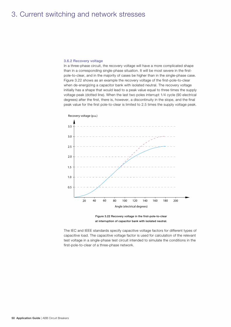
3.6.2 Recovery voltageIn a three-phase circuit, the recovery voltage will have a more complicated shape than in a corresponding single-phase situation. It will be most severe in the first-pole-to-clear, and in the majority of cases be higher than in the single-phase case. Figure 3.22 shows as an example the recovery voltage of the first-pole-to-clear when de-energizing a capacitor bank with isolated neutral. The recovery voltage initially has a shape that would lead to a peak value equal to three times the supply voltage peak (dotted line). When the last two poles interrupt 1/4 cycle (90 electrical degrees) after the first, there is, however, a discontinuity in the slope, and the final peak value for the first pole-to-clear is limited to 2.5 times the supply voltage peak.
Figure 3.22 Recovery voltage in the first-pole-to-clear
at interruption of capacitor bank with isolated neutral.
The IEC and IEEE standards specify capacitive voltage factors for different types of capacitive load. The capacitive voltage factor is used for calculation of the relevant test voltage in a single-phase test circuit intended to simulate the conditions in the first-pole-to-clear of a three-phase network.
3. Current switching and network stresses
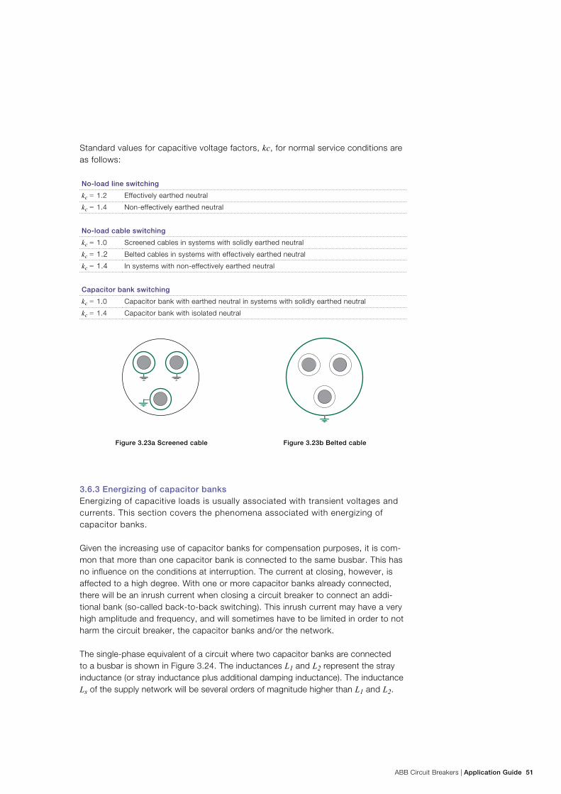
ABB Circuit Breakers | Application Guide 51
Standard values for capacitive voltage factors, kc, for normal service conditions are as follows:
No-load line switching
kc = 1.2 Effectively earthed neutral
kc = 1.4 Non-effectively earthed neutral
No-load cable switching
kc = 1.0 Screened cables in systems with solidly earthed neutral
kc = 1.2 Belted cables in systems with effectively earthed neutral
kc = 1.4 In systems with non-effectively earthed neutral
Capacitor bank switching
kc = 1.0 Capacitor bank with earthed neutral in systems with solidly earthed neutral
kc = 1.4 Capacitor bank with isolated neutral
Figure 3.23a Screened cable Figure 3.23b Belted cable
3.6.3 Energizing of capacitor banksEnergizing of capacitive loads is usually associated with transient voltages and currents. This section covers the phenomena associated with energizing of capacitor banks.
Given the increasing use of capacitor banks for compensation purposes, it is com-mon that more than one capacitor bank is connected to the same busbar. This has no influence on the conditions at interruption. The current at closing, however, is affected to a high degree. With one or more capacitor banks already connected, there will be an inrush current when closing a circuit breaker to connect an addi-tional bank (so-called back-to-back switching). This inrush current may have a very high amplitude and frequency, and will sometimes have to be limited in order to not harm the circuit breaker, the capacitor banks and/or the network.
The single-phase equivalent of a circuit where two capacitor banks are connected to a busbar is shown in Figure 3.24. The inductances L1 and L2 represent the stray inductance (or stray inductance plus additional damping inductance). The inductance Ls of the supply network will be several orders of magnitude higher than L1 and L2.
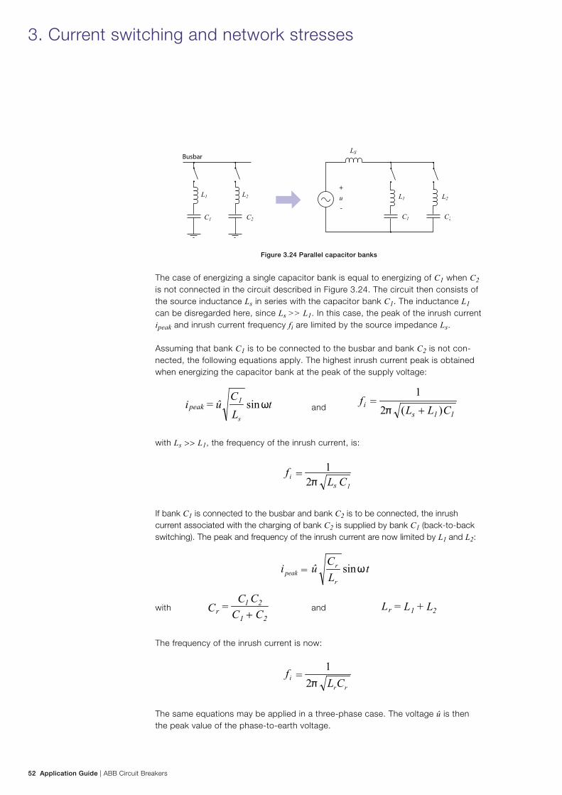
52 Application Guide | ABB Circuit Breakers
Figure 3.24 Parallel capacitor banks
The case of energizing a single capacitor bank is equal to energizing of C1 when C2 is not connected in the circuit described in Figure 3.24. The circuit then consists of the source inductance Ls in series with the capacitor bank C1. The inductance L1 can be disregarded here, since Ls >> L1. In this case, the peak of the inrush current ipeak and inrush current frequency fi are limited by the source impedance Ls.
Assuming that bank C1 is to be connected to the busbar and bank C2 is not con-nected, the following equations apply. The highest inrush current peak is obtained when energizing the capacitor bank at the peak of the supply voltage:
and
with Ls >> L1, the frequency of the inrush current, is:
If bank C1 is connected to the busbar and bank C2 is to be connected, the inrush current associated with the charging of bank C2 is supplied by bank C1 (back-to-back switching). The peak and frequency of the inrush current are now limited by L1 and L2:
with and
The frequency of the inrush current is now:
The same equations may be applied in a three-phase case. The voltage û is then the peak value of the phase-to-earth voltage.
3. Current switching and network stresses
ABB Circuit Breakers | Application Guide 53
Typical amplitudes of the inrush currents for back-to-back energizing of capacitor banks are several kA, with frequencies of 2 - 5 kHz. Capacitor banks can normally withstand amplitudes up to 100 times their rated normal current. For circuit breakers, IEC suggests 20 kA peak at 4.25 kHz as standard withstand capability.
Controlled switching is an attractive and well-proven means of limiting the inrush current amplitude and associated stresses on the equipment. See ABB Controlled Switching, Buyer’s and Application Guide 1HSM 9543 22-01en. In addition, the inrush current amplitude and frequency can be decreased by insertion of additional series inductance in the circuit.
3.7 Inductive load switchingInductive load switching will occur in the following cases:
− switching of shunt reactors − switching of unloaded transformers
The currents to be interrupted are low compared to the short-circuit current, and range from a few amperes to some hundred amperes. Therefore, they are often referred to as “small inductive currents.” After opening of the circuit breaker, the current flows through the arc between the contacts. This arc is stable at high cur-rents, but becomes unstable at low currents in the order of 5 - 10 A, and is usually forced to a premature current zero. This phenomenon of current interruption prior to the natural current zero is usually referred to as current chopping. The resulting chopping overvoltages, and particularly overvoltages due to subsequent reignitions, may be a concern. Controlled switching of the circuit breaker is an efficient way to eliminate the reignition overvoltages. See ABB Controlled Switching, Buyer’s and Application Guide.
3.7.1 Switching of shunt reactorsThe most clear-cut case of inductive load switching is the interruption of a reactor current. The reactor may be directly connected to the network (shunt reactor) or through a transformer (e.g. connected to a tertiary winding). In both cases the load consists of an approximately linear inductance.
A three-phase shunt reactor configuration may differ considerably. The following configurations exist:
− a bank of single-phase reactors − a three-phase unit with a 3-legged core − a three-phase unit with a 5-legged core − a three-phase unit of the shell type
The earthing conditions also may vary:
− solidly earthed neutral − earthing through a neutral reactor − isolated neutral
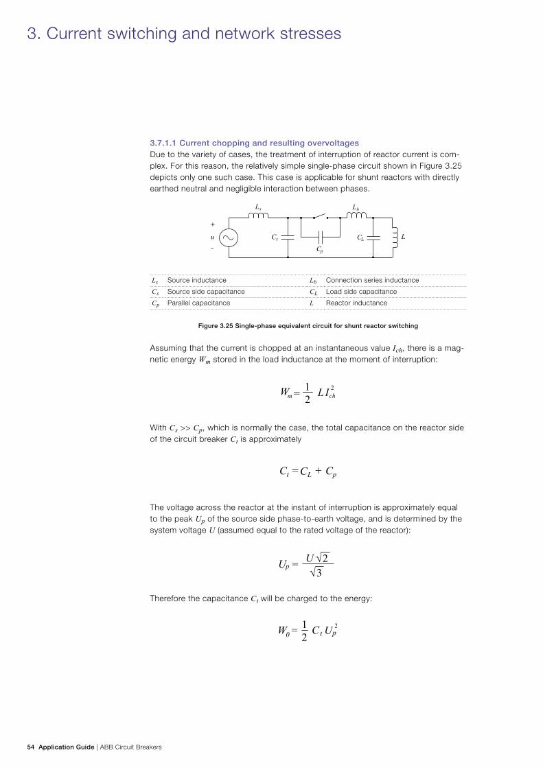
54 Application Guide | ABB Circuit Breakers
3.7.1.1 Current chopping and resulting overvoltagesDue to the variety of cases, the treatment of interruption of reactor current is com-plex. For this reason, the relatively simple single-phase circuit shown in Figure 3.25 depicts only one such case. This case is applicable for shunt reactors with directly earthed neutral and negligible interaction between phases.
Ls Source inductance Lb Connection series inductance
Cs Source side capacitance CL Load side capacitance
Cp Parallel capacitance L Reactor inductance
Figure 3.25 Single-phase equivalent circuit for shunt reactor switching
Assuming that the current is chopped at an instantaneous value Ich, there is a mag-netic energy Wm stored in the load inductance at the moment of interruption:
With Cs >> Cp, which is normally the case, the total capacitance on the reactor side of the circuit breaker Ct is approximately
The voltage across the reactor at the instant of interruption is approximately equal to the peak Up of the source side phase-to-earth voltage, and is determined by the system voltage U (assumed equal to the rated voltage of the reactor):
Therefore the capacitance Ct will be charged to the energy:
3. Current switching and network stresses
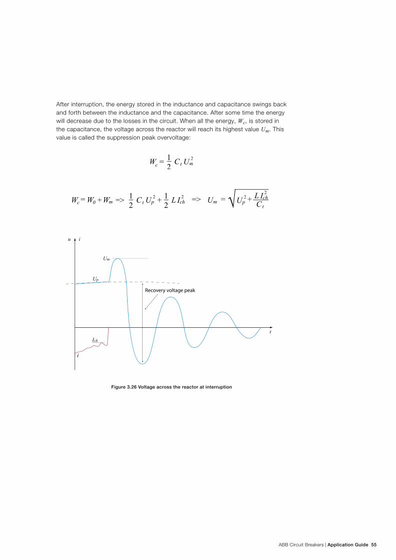
ABB Circuit Breakers | Application Guide 55
After interruption, the energy stored in the inductance and capacitance swings back and forth between the inductance and the capacitance. After some time the energy will decrease due to the losses in the circuit. When all the energy, Wc, is stored in the capacitance, the voltage across the reactor will reach its highest value Um. This value is called the suppression peak overvoltage:
Figure 3.26 Voltage across the reactor at interruption
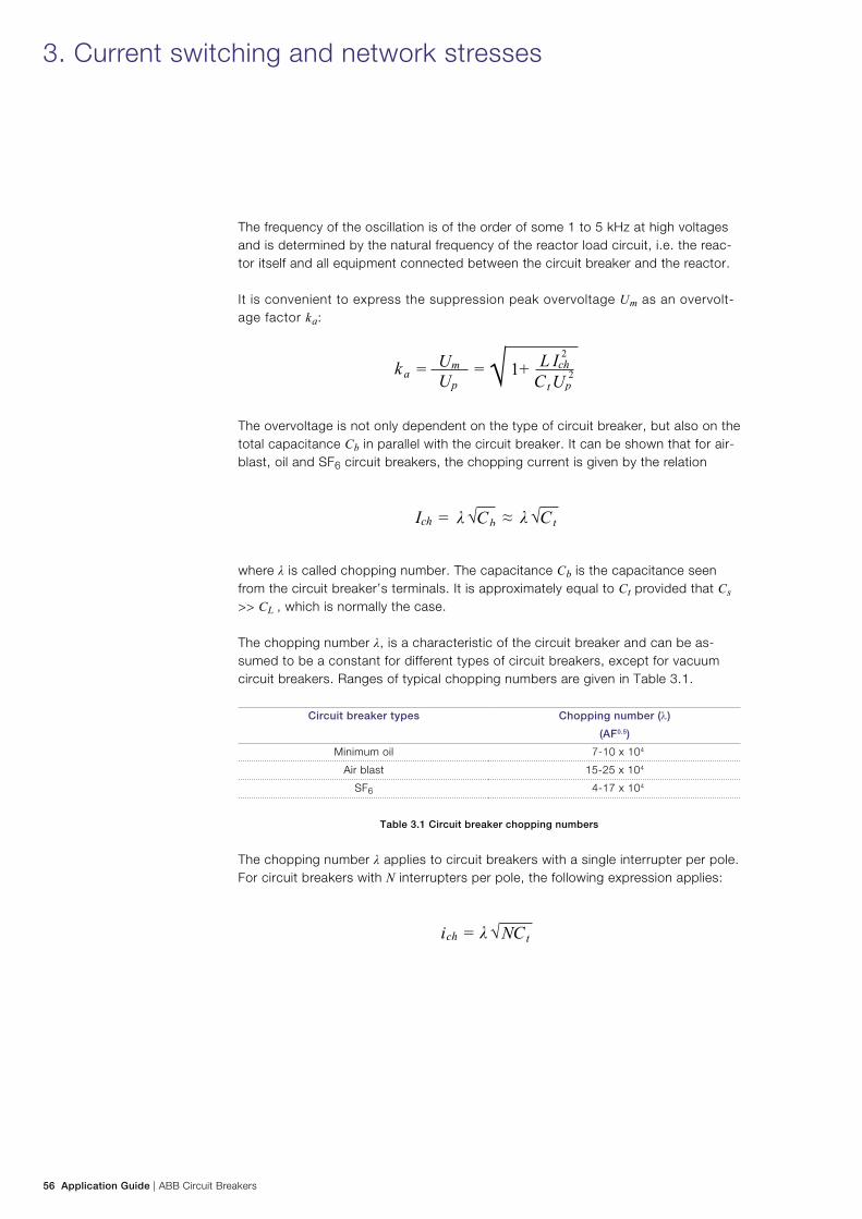
56 Application Guide | ABB Circuit Breakers
The frequency of the oscillation is of the order of some 1 to 5 kHz at high voltages and is determined by the natural frequency of the reactor load circuit, i.e. the reac-tor itself and all equipment connected between the circuit breaker and the reactor.
It is convenient to express the suppression peak overvoltage Um as an overvolt-age factor ka:
The overvoltage is not only dependent on the type of circuit breaker, but also on the total capacitance Cb in parallel with the circuit breaker. It can be shown that for air-blast, oil and SF6 circuit breakers, the chopping current is given by the relation
where λ is called chopping number. The capacitance Cb is the capacitance seen from the circuit breaker’s terminals. It is approximately equal to Ct provided that Cs >> CL , which is normally the case.
The chopping number λ, is a characteristic of the circuit breaker and can be as-sumed to be a constant for different types of circuit breakers, except for vacuum circuit breakers. Ranges of typical chopping numbers are given in Table 3.1.
Circuit breaker types Chopping number (λ)
(AF0.5)
Minimum oil 7-10 x 104
Air blast 15-25 x 104
SF6 4-17 x 104
Table 3.1 Circuit breaker chopping numbers
The chopping number λ applies to circuit breakers with a single interrupter per pole. For circuit breakers with N interrupters per pole, the following expression applies:
3. Current switching and network stresses
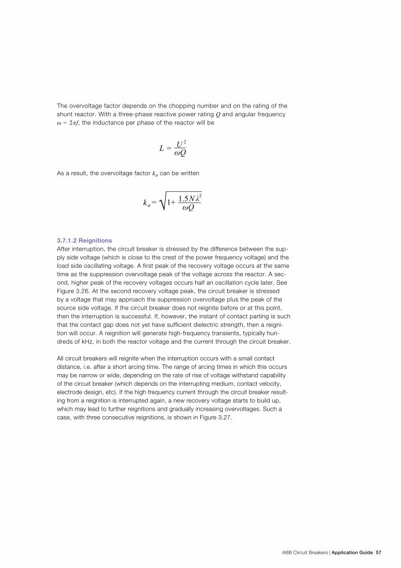
ABB Circuit Breakers | Application Guide 57
The overvoltage factor depends on the chopping number and on the rating of the shunt reactor. With a three-phase reactive power rating Q and angular frequency ω = 2f, the inductance per phase of the reactor will be
As a result, the overvoltage factor ka can be written
3.7.1.2 Reignitions After interruption, the circuit breaker is stressed by the difference between the sup-ply side voltage (which is close to the crest of the power frequency voltage) and the load side oscillating voltage. A first peak of the recovery voltage occurs at the same time as the suppression overvoltage peak of the voltage across the reactor. A sec-ond, higher peak of the recovery voltages occurs half an oscillation cycle later. See Figure 3.26. At the second recovery voltage peak, the circuit breaker is stressed by a voltage that may approach the suppression overvoltage plus the peak of the source side voltage. If the circuit breaker does not reignite before or at this point, then the interruption is successful. If, however, the instant of contact parting is such that the contact gap does not yet have sufficient dielectric strength, then a reigni-tion will occur. A reignition will generate high-frequency transients, typically hun-dreds of kHz, in both the reactor voltage and the current through the circuit breaker.
All circuit breakers will reignite when the interruption occurs with a small contact distance, i.e. after a short arcing time. The range of arcing times in which this occurs may be narrow or wide, depending on the rate of rise of voltage withstand capability of the circuit breaker (which depends on the interrupting medium, contact velocity, electrode design, etc). If the high frequency current through the circuit breaker result-ing from a reignition is interrupted again, a new recovery voltage starts to build up, which may lead to further reignitions and gradually increasing overvoltages. Such a case, with three consecutive reignitions, is shown in Figure 3.27.
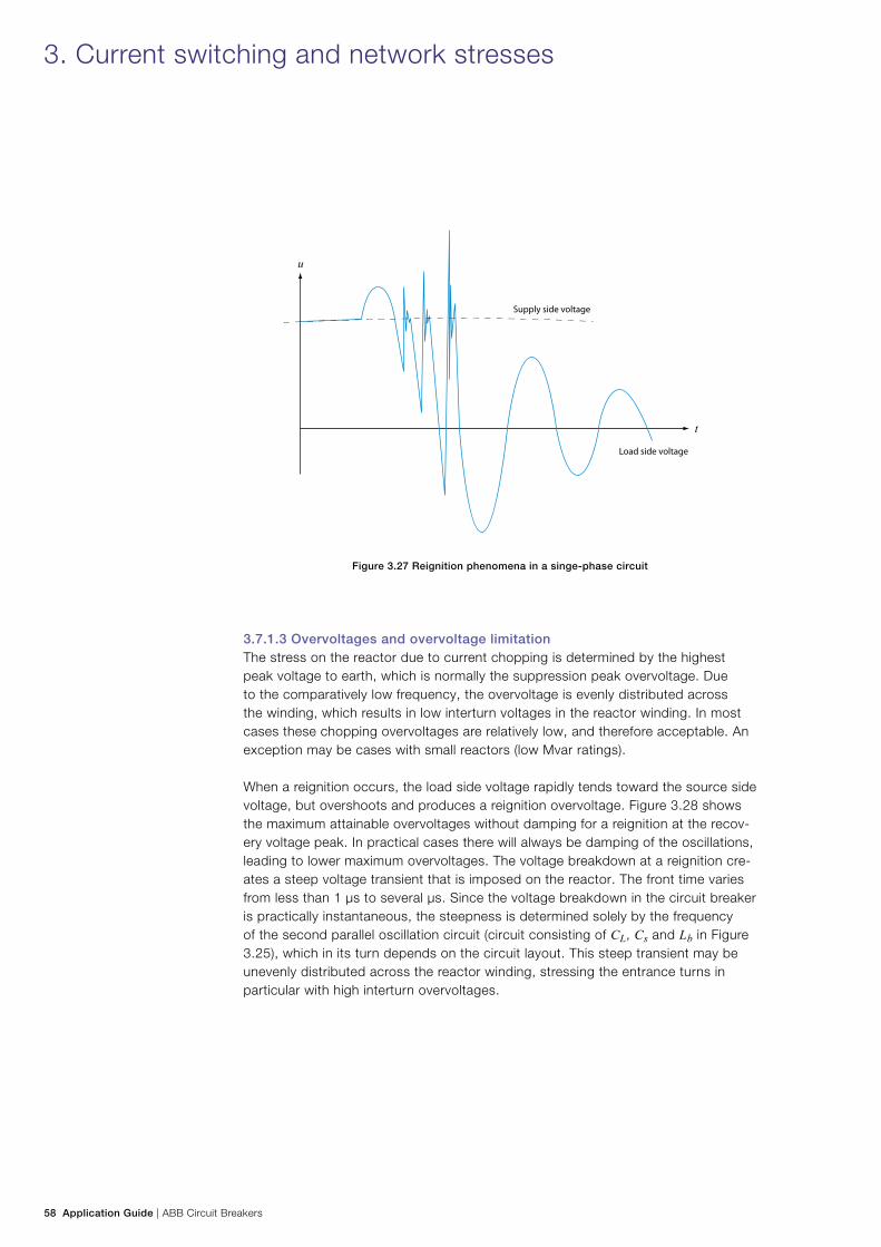
58 Application Guide | ABB Circuit Breakers
Figure 3.27 Reignition phenomena in a singe-phase circuit
3.7.1.3 Overvoltages and overvoltage limitationThe stress on the reactor due to current chopping is determined by the highest peak voltage to earth, which is normally the suppression peak overvoltage. Due to the comparatively low frequency, the overvoltage is evenly distributed across the winding, which results in low interturn voltages in the reactor winding. In most cases these chopping overvoltages are relatively low, and therefore acceptable. An exception may be cases with small reactors (low Mvar ratings).
When a reignition occurs, the load side voltage rapidly tends toward the source side voltage, but overshoots and produces a reignition overvoltage. Figure 3.28 shows the maximum attainable overvoltages without damping for a reignition at the recov-ery voltage peak. In practical cases there will always be damping of the oscillations, leading to lower maximum overvoltages. The voltage breakdown at a reignition cre-ates a steep voltage transient that is imposed on the reactor. The front time varies from less than 1 µs to several µs. Since the voltage breakdown in the circuit breaker is practically instantaneous, the steepness is determined solely by the frequency of the second parallel oscillation circuit (circuit consisting of CL, Cs and Lb in Figure 3.25), which in its turn depends on the circuit layout. This steep transient may be unevenly distributed across the reactor winding, stressing the entrance turns in particular with high interturn overvoltages.
3. Current switching and network stresses
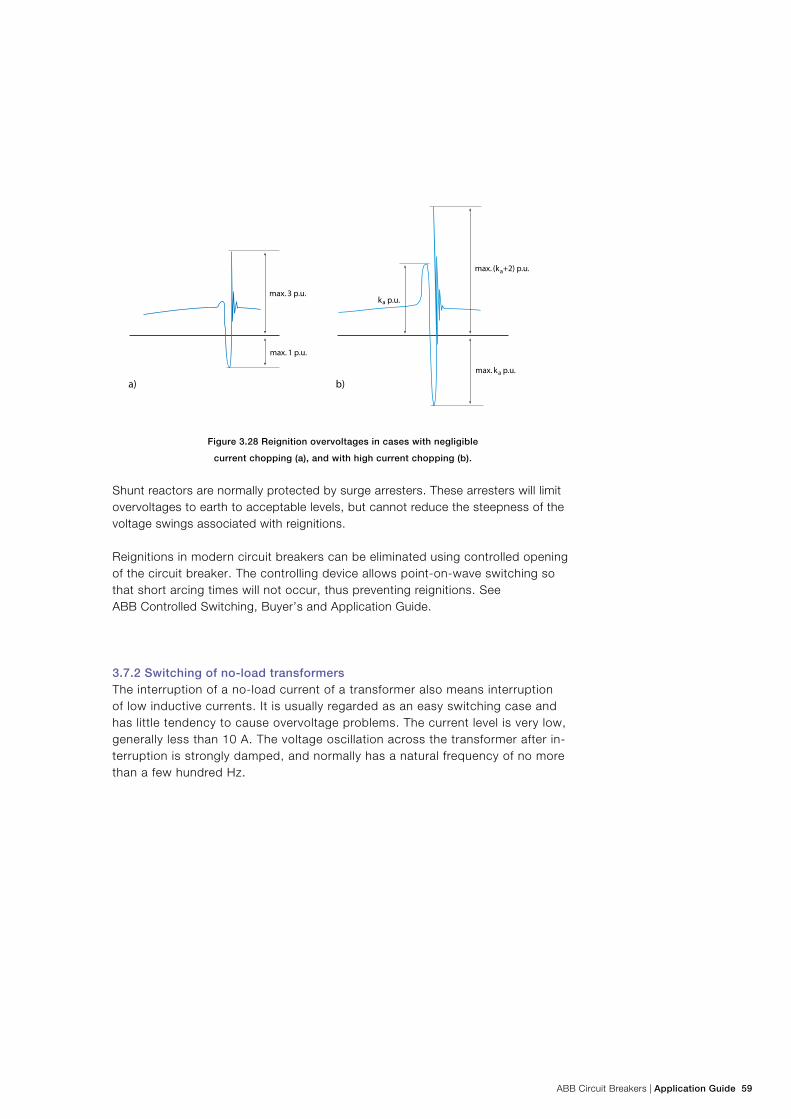
ABB Circuit Breakers | Application Guide 59
Figure 3.28 Reignition overvoltages in cases with negligible
current chopping (a), and with high current chopping (b).
Shunt reactors are normally protected by surge arresters. These arresters will limit overvoltages to earth to acceptable levels, but cannot reduce the steepness of the voltage swings associated with reignitions.
Reignitions in modern circuit breakers can be eliminated using controlled opening of the circuit breaker. The controlling device allows point-on-wave switching so that short arcing times will not occur, thus preventing reignitions. See ABB Controlled Switching, Buyer’s and Application Guide.
3.7.2 Switching of no-load transformersThe interruption of a no-load current of a transformer also means interruption of low inductive currents. It is usually regarded as an easy switching case and has little tendency to cause overvoltage problems. The current level is very low, generally less than 10 A. The voltage oscillation across the transformer after in-terruption is strongly damped, and normally has a natural frequency of no more than a few hundred Hz.
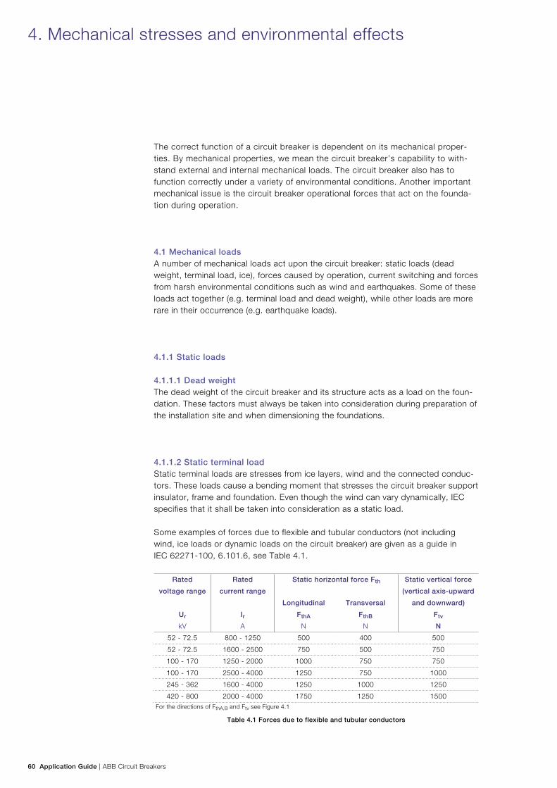
60 Application Guide | ABB Circuit Breakers
4. Mechanical stresses and environmental effects
The correct function of a circuit breaker is dependent on its mechanical proper-ties. By mechanical properties, we mean the circuit breaker’s capability to with-stand external and internal mechanical loads. The circuit breaker also has to function correctly under a variety of environmental conditions. Another important mechanical issue is the circuit breaker operational forces that act on the founda-tion during operation.
4.1 Mechanical loadsA number of mechanical loads act upon the circuit breaker: static loads (dead weight, terminal load, ice), forces caused by operation, current switching and forces from harsh environmental conditions such as wind and earthquakes. Some of these loads act together (e.g. terminal load and dead weight), while other loads are more rare in their occurrence (e.g. earthquake loads).
4.1.1 Static loads 4.1.1.1 Dead weightThe dead weight of the circuit breaker and its structure acts as a load on the foun-dation. These factors must always be taken into consideration during preparation of the installation site and when dimensioning the foundations.
4.1.1.2 Static terminal loadStatic terminal loads are stresses from ice layers, wind and the connected conduc-tors. These loads cause a bending moment that stresses the circuit breaker support insulator, frame and foundation. Even though the wind can vary dynamically, IEC specifies that it shall be taken into consideration as a static load.
Some examples of forces due to flexible and tubular conductors (not including wind, ice loads or dynamic loads on the circuit breaker) are given as a guide in IEC 62271-100, 6.101.6, see Table 4.1.
Rated
voltage range
Ur
kV
Rated
current range
IrA
Static horizontal force Fth Static vertical force
(vertical axis-upward
and downward)
Ftv
N
Longitudinal
FthA
N
Transversal
FthB
N
52 - 72.5 800 - 1250 500 400 500
52 - 72.5 1600 - 2500 750 500 750
100 - 170 1250 - 2000 1000 750 750
100 - 170 2500 - 4000 1250 750 1000
245 - 362 1600 - 4000 1250 1000 1250
420 - 800 2000 - 4000 1750 1250 1500For the directions of FthA,B and Ftv see Figure 4.1
Table 4.1 Forces due to flexible and tubular conductors
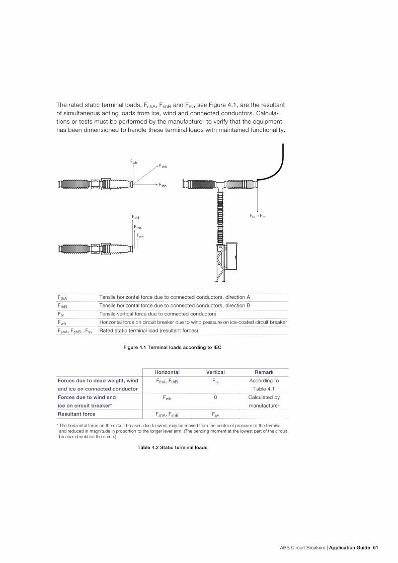
ABB Circuit Breakers | Application Guide 61
The rated static terminal loads, FshA, FshB and Fsv, see Figure 4.1, are the resultant of simultaneous acting loads from ice, wind and connected conductors. Calcula-tions or tests must be performed by the manufacturer to verify that the equipment has been dimensioned to handle these terminal loads with maintained functionality.
FthA Tensile horizontal force due to connected conductors, direction A
FthB Tensile horizontal force due to connected conductors, direction B
Ftv Tensile vertical force due to connected conductors
Fwh Horizontal force on circuit breaker due to wind pressure on ice-coated circuit breaker
FshA, FshB , Fsv Rated static terminal load (resultant forces)
Figure 4.1 Terminal loads according to IEC
Horizontal Vertical Remark
Forces due to dead weight, wind
and ice on connected conductor
FthA, FthB Ftv According to
Table 4.1
Forces due to wind and
ice on circuit breaker*
Fwh 0 Calculated by
manufacturer
Resultant force FshA, FshB Fsv
* The horizontal force on the circuit breaker, due to wind, may be moved from the centre of pressure to the terminal and reduced in magnitude in proportion to the longer lever arm. (The bending moment at the lowest part of the circuit breaker should be the same.)
Table 4.2 Static terminal loads
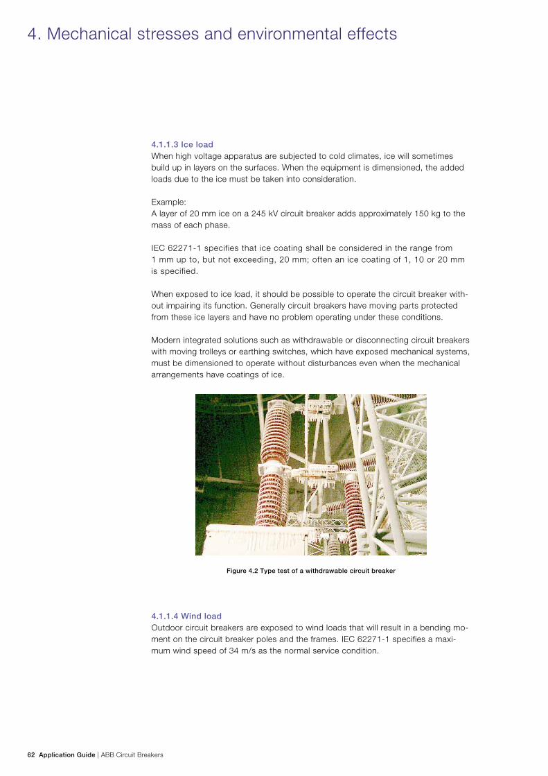
62 Application Guide | ABB Circuit Breakers
4.1.1.3 Ice load When high voltage apparatus are subjected to cold climates, ice will sometimes build up in layers on the surfaces. When the equipment is dimensioned, the added loads due to the ice must be taken into consideration.
Example: A layer of 20 mm ice on a 245 kV circuit breaker adds approximately 150 kg to the mass of each phase.
IEC 62271-1 specifies that ice coating shall be considered in the range from 1 mm up to, but not exceeding, 20 mm; often an ice coating of 1, 10 or 20 mm is specified.
When exposed to ice load, it should be possible to operate the circuit breaker with-out impairing its function. Generally circuit breakers have moving parts protected from these ice layers and have no problem operating under these conditions.
Modern integrated solutions such as withdrawable or disconnecting circuit breakers with moving trolleys or earthing switches, which have exposed mechanical systems, must be dimensioned to operate without disturbances even when the mechanical arrangements have coatings of ice.
Figure 4.2 Type test of a withdrawable circuit breaker
4.1.1.4 Wind loadOutdoor circuit breakers are exposed to wind loads that will result in a bending mo-ment on the circuit breaker poles and the frames. IEC 62271-1 specifies a maxi-mum wind speed of 34 m/s as the normal service condition.
4. Mechanical stresses and environmental effects
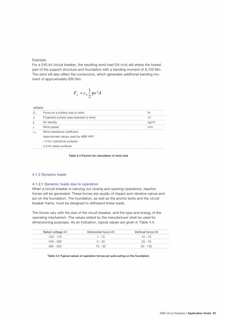
ABB Circuit Breakers | Application Guide 63
Example: For a 245 kV circuit breaker, the resulting wind load (34 m/s) will stress the lowest part of the support structure and foundation with a bending moment of 9,100 Nm. The wind will also affect the conductors, which generates additional bending mo-ment of approximately 650 Nm.
where:Fw Force on a surface due to wind N
A Projected surface area exposed to wind m2
ρ Air density kg/m3
v Wind speed m/s
cw Wind resistance coefficient
Approximate values used by ABB HVP:
1.0 for cylindrical surfaces
2.0 for plane surfaces
Table 4.3 Factors for calculation of wind load
4.1.2 Dynamic loads
4.1.2.1 Dynamic loads due to operationWhen a circuit breaker is carrying out closing and opening operations, reaction forces will be generated. These forces are usually of impact and vibrative nature and act on the foundation. The foundation, as well as the anchor bolts and the circuit breaker frame, must be designed to withstand these loads.
The forces vary with the size of the circuit breaker, and the type and energy of the operating mechanism. The values stated by the manufacturer shall be used for dimensioning purposes. As an indication, typical values are given in Table 4.4.
Rated voltage kV Horizontal force kN Vertical force kN
123 - 170 1 - 15 10 - 75
245 - 300 5 - 20 25 - 75
362 - 550 10 - 30 50 - 120
Table 4.4 Typical values of operation forces per pole acting on the foundation
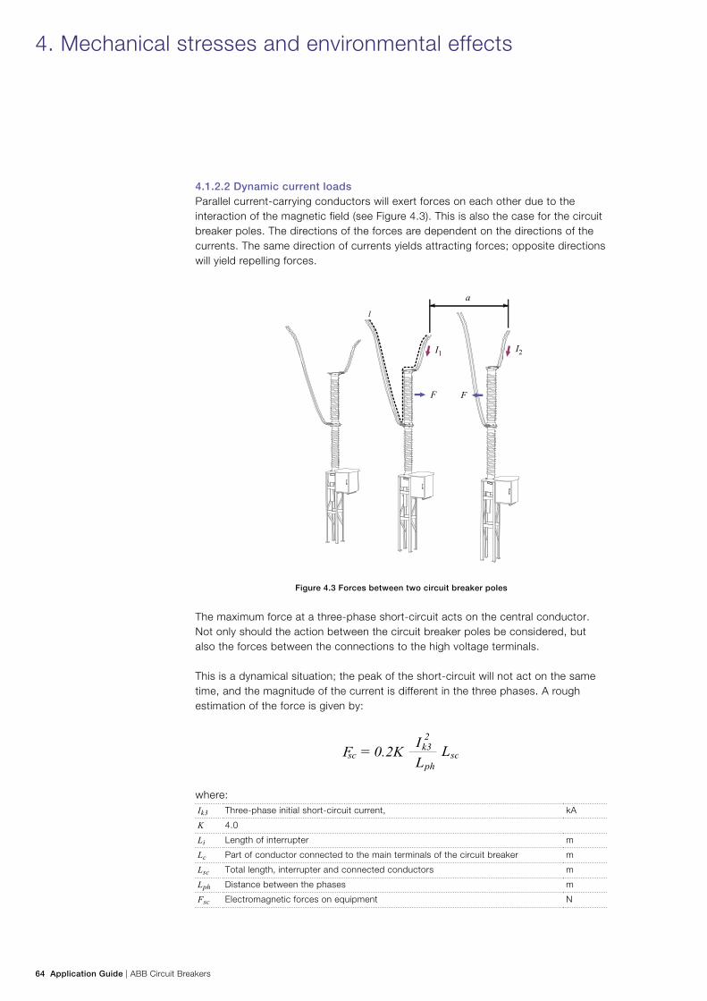
64 Application Guide | ABB Circuit Breakers
4.1.2.2 Dynamic current loadsParallel current-carrying conductors will exert forces on each other due to the interaction of the magnetic field (see Figure 4.3). This is also the case for the circuit breaker poles. The directions of the forces are dependent on the directions of the currents. The same direction of currents yields attracting forces; opposite directions will yield repelling forces.
Figure 4.3 Forces between two circuit breaker poles
The maximum force at a three-phase short-circuit acts on the central conductor. Not only should the action between the circuit breaker poles be considered, but also the forces between the connections to the high voltage terminals.
This is a dynamical situation; the peak of the short-circuit will not act on the same time, and the magnitude of the current is different in the three phases. A rough estimation of the force is given by:
where:Ik3 Three-phase initial short-circuit current, kA
K 4.0
Li Length of interrupter m
Lc Part of conductor connected to the main terminals of the circuit breaker m
Lsc Total length, interrupter and connected conductors m
Lph Distance between the phases m
Fsc Electromagnetic forces on equipment N
4. Mechanical stresses and environmental effects
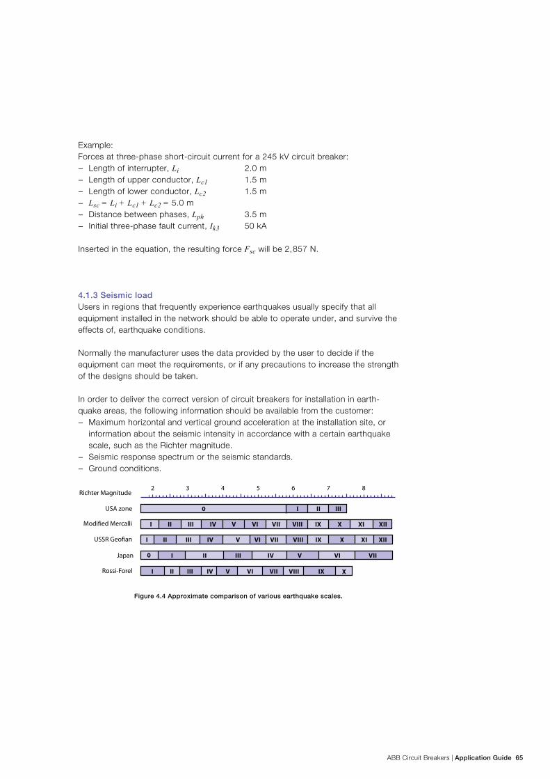
ABB Circuit Breakers | Application Guide 65
Example: Forces at three-phase short-circuit current for a 245 kV circuit breaker:
− Length of interrupter, Li 2.0 m − Length of upper conductor, Lc1 1.5 m − Length of lower conductor, Lc2 1.5 m − Lsc = Li + Lc1 + Lc2 = 5.0 m − Distance between phases, Lph 3.5 m − Initial three-phase fault current, Ik3 50 kA
Inserted in the equation, the resulting force Fsc will be 2, 857 N.
4.1.3 Seismic load Users in regions that frequently experience earthquakes usually specify that all equipment installed in the network should be able to operate under, and survive the effects of, earthquake conditions.
Normally the manufacturer uses the data provided by the user to decide if the equipment can meet the requirements, or if any precautions to increase the strength of the designs should be taken.
In order to deliver the correct version of circuit breakers for installation in earth-quake areas, the following information should be available from the customer:
− Maximum horizontal and vertical ground acceleration at the installation site, or information about the seismic intensity in accordance with a certain earthquake scale, such as the Richter magnitude.
− Seismic response spectrum or the seismic standards. − Ground conditions.
Figure 4.4 Approximate comparison of various earthquake scales.
0 I II III
I II III IV V VI VII VIII IX X XI XII
I II III IV V VI VII VIII IX X XI XII
I II III IV V VI VII
I II III IV V VI VII
0
VIII IX X
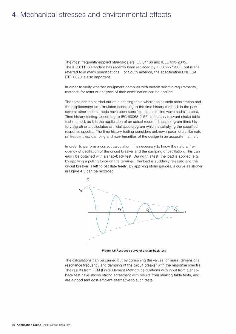
66 Application Guide | ABB Circuit Breakers
The most frequently-applied standards are IEC 61166 and IEEE 693-2005. The IEC 61166 standard has recently been replaced by IEC 62271-300, but is still referred to in many specifications. For South America, the specification ENDESA ETG1.020 is also important.
In order to verify whether equipment complies with certain seismic requirements, methods for tests or analyses of their combination can be applied.
The tests can be carried out on a shaking table where the seismic acceleration and the displacement are simulated according to the time history method. In the past several other test methods have been specified, such as sine wave and sine beat. Time history testing, according to IEC 60068-2-57, is the only relevant shake table test method, as it is the application of an actual recorded accelerogram (time his-tory signal) or a calculated artificial accelerogram which is satisfying the specified response spectra. The time history testing considers unknown parameters like natu-ral frequencies, damping and non-linearities of the design in an accurate manner.
In order to perform a correct calculation, it is necessary to know the natural fre-quency of oscillation of the circuit breaker and the damping of oscillation. This can easily be obtained with a snap-back test. During this test, the load is applied (e.g. by applying a pulling force on the terminal), the load is suddenly released and the circuit breaker is left to oscillate freely. By applying strain gauges, a curve as shown in Figure 4.5 can be recorded.
Figure 4.5 Response curve of a snap-back test
The calculations can be carried out by combining the values for mass, dimensions, resonance frequency and damping of the circuit breaker with the response spectra. The results from FEM (Finite Element Method) calculations with input from a snap-back test have shown strong agreement with results from shaking table tests, and are a good and cost-efficient alternative to such tests.
4. Mechanical stresses and environmental effects
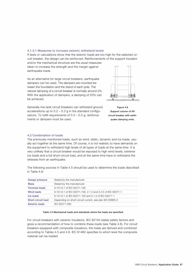
ABB Circuit Breakers | Application Guide 67
4.1.3.1 Measures to increase seismic withstand levelsIf tests or calculations show that the seismic loads are too high for the selected cir-cuit breaker, the design can be reinforced. Reinforcements of the support insulator and/or the mechanical structure are the usual measures taken to increase the strength and the margin against earthquake loads.
As an alternative for large circuit breakers, earthquake dampers can be used. The dampers are mounted be-tween the foundation and the stand of each pole. The natural damping of a circuit breaker is normally around 2%. With the application of dampers, a damping of 20% can be achieved.
Generally live tank circuit breakers can withstand ground accelerations up to 0.2 – 0.3 g in the standard configu-rations. To fulfill requirements of 0.3 – 0.5 g, reinforce-ments or dampers must be used.
4.2 Combination of loadsThe previously-mentioned loads, such as wind, static, dynamic and ice loads, usu-ally act together at the same time. Of course, it is not realistic to have demands on the equipment to withstand high levels of all types of loads at the same time. It is very unlikely that a circuit breaker would be exposed to high wind levels, extreme ice loads and a full short-circuit load, and at the same time have to withstand the stresses from an earthquake.
The following sources in Table 4.5 should be used to determine the loads described in Table 4.6:
Design pressure Stated by the manufacturer
Mass Stated by the manufacturer
Terminal loads 6.101.6.1 of IEC 62271-100
Wind loads 6.101.6.1 of IEC 62271-100, 2.1.2 and 2.2.5 of IEC 62271-1
Ice loads 6.101.6.1 of IEC 62271-100 and 2.1.2 of IEC 62271-1
Short-circuit load Depending on short-circuit current, see also IEC 60865-2
Seismic loads IEC 62271-300
Table 4.5 Mechanical loads and standards where the loads are specified.
For circuit breakers with ceramic insulators, IEC 62155 states safety factors and gives a recommendation of how to combine these loads (see Table 4.6). For circuit breakers equipped with composite insulators, the loads are derived and combined according to Tables 4.5 and 4.6. IEC 61462 specifies to which level the composite material can be loaded.
Figure 4.6
Support column of HV
circuit breaker with earth-
quake damping units.
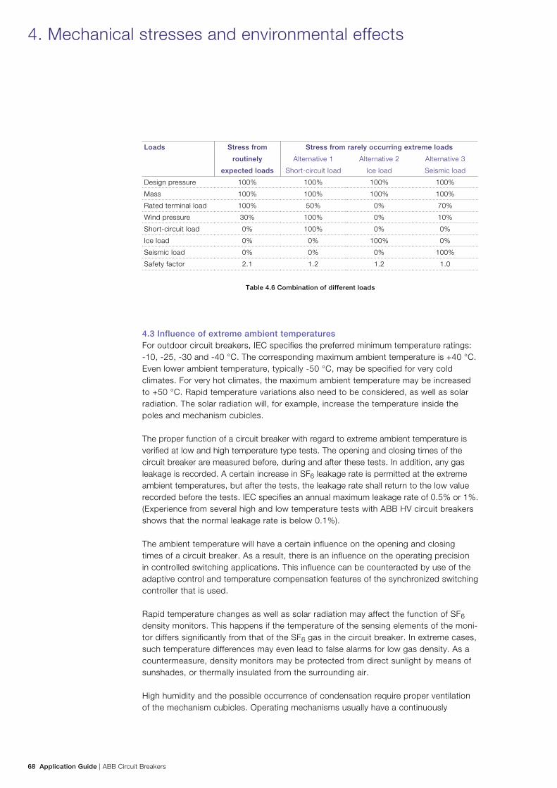
68 Application Guide | ABB Circuit Breakers
Loads Stress from
routinely
expected loads
Stress from rarely occurring extreme loads
Alternative 1
Short-circuit load
Alternative 2
Ice load
Alternative 3
Seismic load
Design pressure 100% 100% 100% 100%
Mass 100% 100% 100% 100%
Rated terminal load 100% 50% 0% 70%
Wind pressure 30% 100% 0% 10%
Short-circuit load 0% 100% 0% 0%
Ice load 0% 0% 100% 0%
Seismic load 0% 0% 0% 100%
Safety factor 2.1 1.2 1.2 1.0
Table 4.6 Combination of different loads
4.3 Influence of extreme ambient temperaturesFor outdoor circuit breakers, IEC specifies the preferred minimum temperature ratings: -10, -25, -30 and -40 °C. The corresponding maximum ambient temperature is +40 °C. Even lower ambient temperature, typically -50 °C, may be specified for very cold climates. For very hot climates, the maximum ambient temperature may be increased to +50 °C. Rapid temperature variations also need to be considered, as well as solar radiation. The solar radiation will, for example, increase the temperature inside the poles and mechanism cubicles.
The proper function of a circuit breaker with regard to extreme ambient temperature is verified at low and high temperature type tests. The opening and closing times of the circuit breaker are measured before, during and after these tests. In addition, any gas leakage is recorded. A certain increase in SF6 leakage rate is permitted at the extreme ambient temperatures, but after the tests, the leakage rate shall return to the low value recorded before the tests. IEC specifies an annual maximum leakage rate of 0.5% or 1%. (Experience from several high and low temperature tests with ABB HV circuit breakers shows that the normal leakage rate is below 0.1%).
The ambient temperature will have a certain influence on the opening and closing times of a circuit breaker. As a result, there is an influence on the operating precision in controlled switching applications. This influence can be counteracted by use of the adaptive control and temperature compensation features of the synchronized switching controller that is used.
Rapid temperature changes as well as solar radiation may affect the function of SF6 density monitors. This happens if the temperature of the sensing elements of the moni-tor differs significantly from that of the SF6 gas in the circuit breaker. In extreme cases, such temperature differences may even lead to false alarms for low gas density. As a countermeasure, density monitors may be protected from direct sunlight by means of sunshades, or thermally insulated from the surrounding air.
High humidity and the possible occurrence of condensation require proper ventilation of the mechanism cubicles. Operating mechanisms usually have a continuously
4. Mechanical stresses and environmental effects
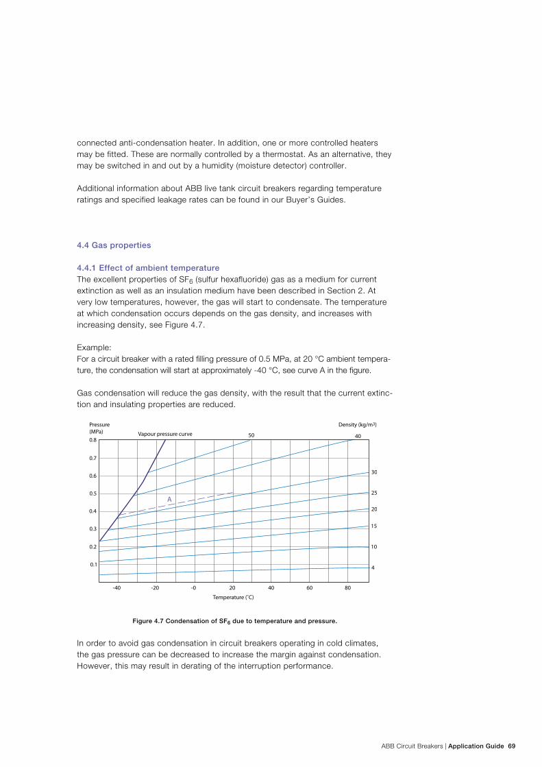
ABB Circuit Breakers | Application Guide 69
connected anti-condensation heater. In addition, one or more controlled heaters may be fitted. These are normally controlled by a thermostat. As an alternative, they may be switched in and out by a humidity (moisture detector) controller.
Additional information about ABB live tank circuit breakers regarding temperature ratings and specified leakage rates can be found in our Buyer’s Guides.
4.4 Gas properties
4.4.1 Effect of ambient temperatureThe excellent properties of SF6 (sulfur hexafluoride) gas as a medium for current extinction as well as an insulation medium have been described in Section 2. At very low temperatures, however, the gas will start to condensate. The temperature at which condensation occurs depends on the gas density, and increases with increasing density, see Figure 4.7.
Example: For a circuit breaker with a rated filling pressure of 0.5 MPa, at 20 °C ambient tempera-ture, the condensation will start at approximately -40 °C, see curve A in the figure.
Gas condensation will reduce the gas density, with the result that the current extinc-tion and insulating properties are reduced.
Figure 4.7 Condensation of SF6 due to temperature and pressure.
In order to avoid gas condensation in circuit breakers operating in cold climates, the gas pressure can be decreased to increase the margin against condensation. However, this may result in derating of the interruption performance.
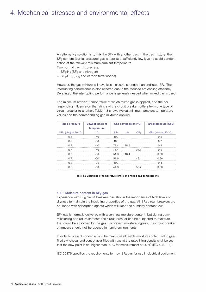
70 Application Guide | ABB Circuit Breakers
An alternative solution is to mix the SF6 with another gas. In the gas mixture, the SF6 content (partial pressure) gas is kept at a sufficiently low level to avoid conden-sation at the relevant minimum ambient temperature. Two normal gas mixtures are:
− SF6/N2 (SF6 and nitrogen) − SF6/CF4 (SF6 and carbon tetrafluoride)
However, the gas mixture will have less dielectric strength than undiluted SF6. The interrupting performance is also affected due to the reduced arc cooling efficiency. Derating of the interrupting performance is generally needed when mixed gas is used.
The minimum ambient temperature at which mixed gas is applied, and the cor-responding influence on the ratings of the circuit breaker, differs from one type of circuit breaker to another. Table 4.8 shows typical minimum ambient temperature values and the corresponding gas mixtures applied.
Rated pressure Lowest ambient
temperature
Gas composition (%) Partial pressure (SF6)
MPa (abs) at 20 °C °C SF6 N2 CF4 MPa (abs) at 20 °C
0.5 -40 100 0.5
0.7 -30 100 0.7
0.7 -40 71.4 28.6 0.5
0.7 -40 71.4 28.6 0.5
0.7 -50 51.6 48.4 0.36
0.7 -50 51.6 48.4 0.36
0.8 -25 100 0.8
0.8 -50 44.3 55.7 0.36
Table 4.8 Examples of temperature limits and mixed gas compositions
4.4.2 Moisture content in SF6 gas Experience with SF6 circuit breakers has shown the importance of high levels of dryness to maintain the insulating properties of the gas. All SF6 circuit breakers are equipped with adsorption agents which will keep the humidity content low.
SF6 gas is normally delivered with a very low moisture content, but during com-missioning and refurbishments the circuit breaker can be subjected to moisture that could be absorbed by the gas. To prevent moisture ingress, the circuit breaker chambers should not be opened in humid environments.
In order to prevent condensation, the maximum allowable moisture content within gas-filled switchgear and control gear filled with gas at the rated filling density shall be such that the dew-point is not higher than -5 °C for measurement at 20 °C (IEC 62271-1).
IEC 60376 specifies the requirements for new SF6 gas for use in electrical equipment.
4. Mechanical stresses and environmental effects
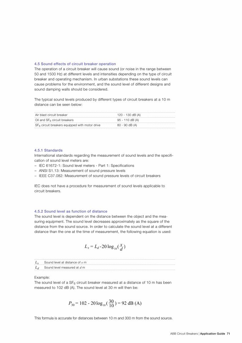
ABB Circuit Breakers | Application Guide 71
4.5 Sound effects of circuit breaker operationThe operation of a circuit breaker will cause sound (or noise in the range between 50 and 1500 Hz) at different levels and intensities depending on the type of circuit breaker and operating mechanism. In urban substations these sound levels can cause problems for the environment, and the sound level of different designs and sound damping walls should be considered.
The typical sound levels produced by different types of circuit breakers at a 10 m distance can be seen below:
Air blast circuit breaker 120 - 130 dB (A)
Oil and SF6 circuit breakers 95 - 110 dB (A)
SF6 circuit breakers equipped with motor drive 80 - 90 dB (A)
4.5.1 Standards International standards regarding the measurement of sound levels and the specifi-cation of sound level meters are:
− IEC 61672-1: Sound level meters - Part 1: Specifications − ANSI S1.13: Measurement of sound pressure levels − IEEE C37.082: Measurement of sound pressure levels of circuit breakers
IEC does not have a procedure for measurement of sound levels applicable to circuit breakers.
4.5.2 Sound level as function of distanceThe sound level is dependent on the distance between the object and the mea-suring equipment. The sound level decreases approximately as the square of the distance from the sound source. In order to calculate the sound level at a different distance than the one at the time of measurement, the following equation is used:
Lx Sound level at distance of x m
Ld Sound level measured at d m
Example: The sound level of a SF6 circuit breaker measured at a distance of 10 m has been measured to 102 dB (A). The sound level at 30 m will then be:
This formula is accurate for distances between 10 m and 300 m from the sound source.
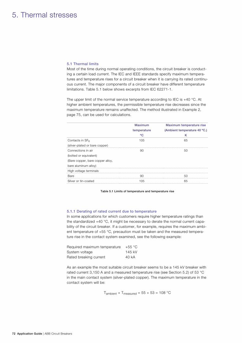
72 Application Guide | ABB Circuit Breakers
5. Thermal stresses
5.1 Thermal limitsMost of the time during normal operating conditions, the circuit breaker is conduct-ing a certain load current. The IEC and IEEE standards specify maximum tempera-tures and temperature rises for a circuit breaker when it is carrying its rated continu-ous current. The major components of a circuit breaker have different temperature limitations. Table 5.1 below shows excerpts from IEC 62271-1.
The upper limit of the normal service temperature according to IEC is +40 °C. At higher ambient temperatures, the permissible temperature rise decreases since the maximum temperature remains unaffected. The method illustrated in Example 2, page 75, can be used for calculations.
Maximum
temperature
Maximum temperature rise
(Ambient temperature 40 ºC.)
ºC K
Contacts in SF6
(silver-plated or bare copper)
105 65
Connections in air
(bolted or equivalent)
(Bare copper, bare copper alloy,
bare aluminum alloy)
90 50
High voltage terminals
Bare 90 50
Silver or tin-coated 105 65
Table 5.1 Limits of temperature and temperature rise
5.1.1 Derating of rated current due to temperatureIn some applications for which customers require higher temperature ratings than the standardized +40 °C, it might be necessary to derate the normal current capa-bility of the circuit breaker. If a customer, for example, requires the maximum ambi-ent temperature of +55 °C, precaution must be taken and the measured tempera-ture rise in the contact system examined, see the following example: Required maximum temperature +55 °C System voltage 145 kV Rated breaking current 40 kA
As an example the most suitable circuit breaker seems to be a 145 kV breaker with rated current 3,150 A and a measured temperature rise (see Section 5.2) of 53 °C in the main contact system (silver-plated copper). The maximum temperature in the contact system will be:
Tambient + Tmeasured = 55 + 53 = 108 °C
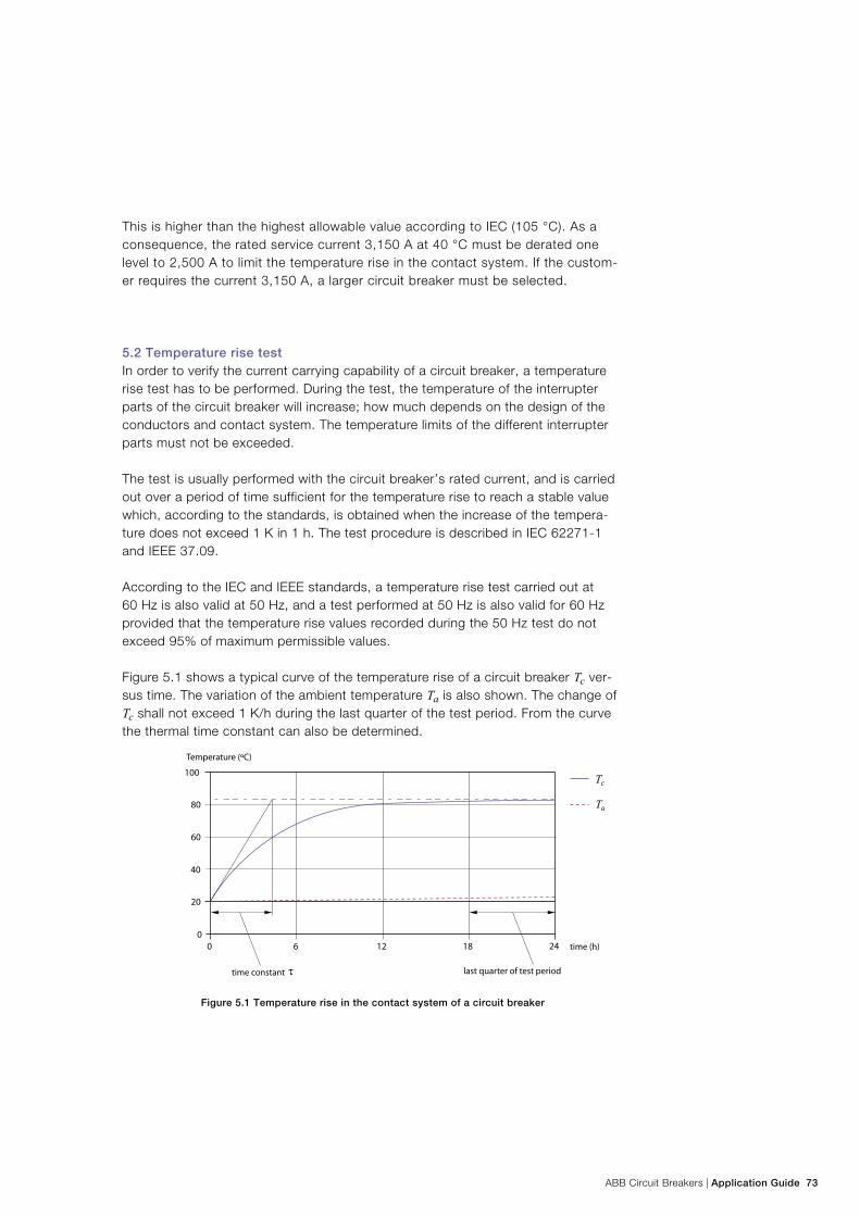
ABB Circuit Breakers | Application Guide 73
This is higher than the highest allowable value according to IEC (105 °C). As a consequence, the rated service current 3,150 A at 40 °C must be derated one level to 2,500 A to limit the temperature rise in the contact system. If the custom-er requires the current 3,150 A, a larger circuit breaker must be selected.
5.2 Temperature rise testIn order to verify the current carrying capability of a circuit breaker, a temperature rise test has to be performed. During the test, the temperature of the interrupter parts of the circuit breaker will increase; how much depends on the design of the conductors and contact system. The temperature limits of the different interrupter parts must not be exceeded.
The test is usually performed with the circuit breaker’s rated current, and is carried out over a period of time sufficient for the temperature rise to reach a stable value which, according to the standards, is obtained when the increase of the tempera-ture does not exceed 1 K in 1 h. The test procedure is described in IEC 62271-1 and IEEE 37.09.
According to the IEC and IEEE standards, a temperature rise test carried out at 60 Hz is also valid at 50 Hz, and a test performed at 50 Hz is also valid for 60 Hz provided that the temperature rise values recorded during the 50 Hz test do not exceed 95% of maximum permissible values.
Figure 5.1 shows a typical curve of the temperature rise of a circuit breaker Tc ver-sus time. The variation of the ambient temperature Ta is also shown. The change of Tc shall not exceed 1 K/h during the last quarter of the test period. From the curve the thermal time constant can also be determined.
Figure 5.1 Temperature rise in the contact system of a circuit breaker
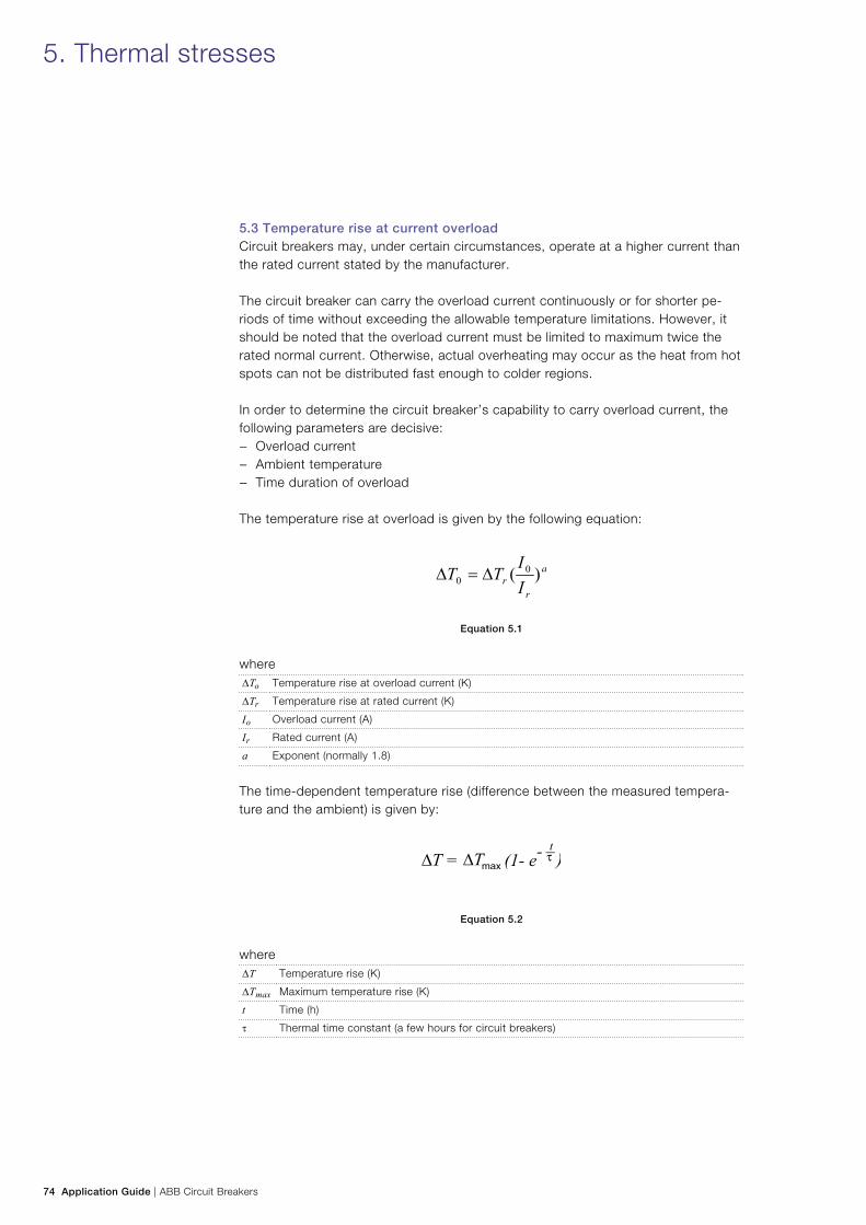
74 Application Guide | ABB Circuit Breakers
5.3 Temperature rise at current overloadCircuit breakers may, under certain circumstances, operate at a higher current than the rated current stated by the manufacturer.
The circuit breaker can carry the overload current continuously or for shorter pe-riods of time without exceeding the allowable temperature limitations. However, it should be noted that the overload current must be limited to maximum twice the rated normal current. Otherwise, actual overheating may occur as the heat from hot spots can not be distributed fast enough to colder regions.
In order to determine the circuit breaker’s capability to carry overload current, the following parameters are decisive:
− Overload current − Ambient temperature − Time duration of overload
The temperature rise at overload is given by the following equation:
Equation 5.1
where ∆To Temperature rise at overload current (K)
∆Tr Temperature rise at rated current (K)
Io Overload current (A)
Ir Rated current (A)
a Exponent (normally 1.8)
The time-dependent temperature rise (difference between the measured tempera-ture and the ambient) is given by:
Equation 5.2
where∆T Temperature rise (K)
∆Tmax Maximum temperature rise (K)
t Time (h)
τ Thermal time constant (a few hours for circuit breakers)
5. Thermal stresses
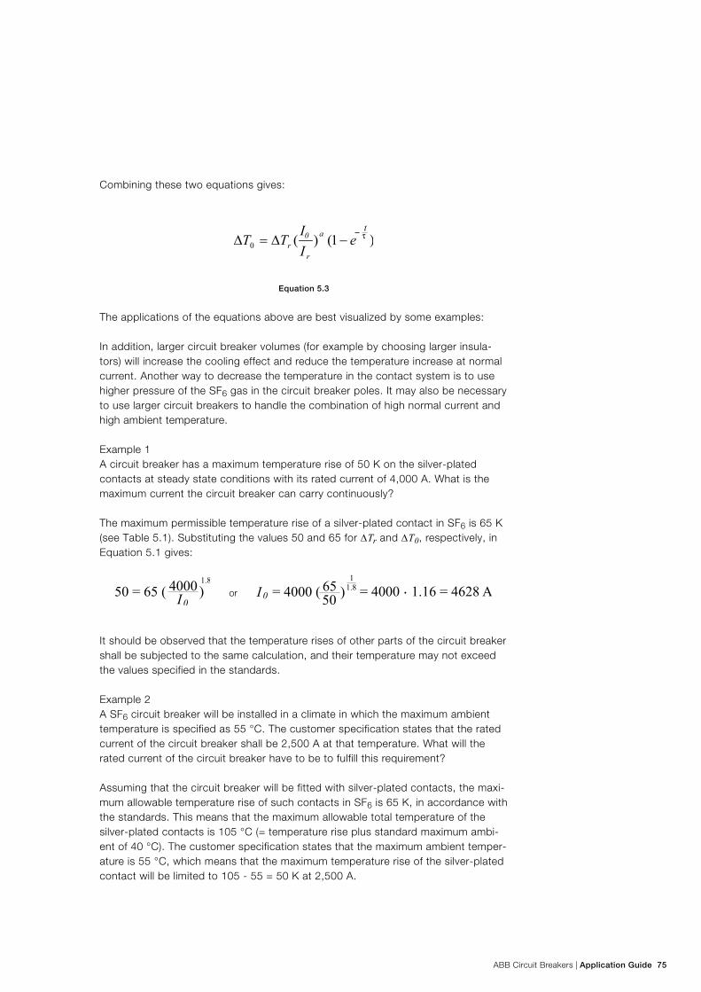
ABB Circuit Breakers | Application Guide 75
Combining these two equations gives:
Equation 5.3
The applications of the equations above are best visualized by some examples:
In addition, larger circuit breaker volumes (for example by choosing larger insula-tors) will increase the cooling effect and reduce the temperature increase at normal current. Another way to decrease the temperature in the contact system is to use higher pressure of the SF6 gas in the circuit breaker poles. It may also be necessary to use larger circuit breakers to handle the combination of high normal current and high ambient temperature.
Example 1A circuit breaker has a maximum temperature rise of 50 K on the silver-plated contacts at steady state conditions with its rated current of 4,000 A. What is the maximum current the circuit breaker can carry continuously?
The maximum permissible temperature rise of a silver-plated contact in SF6 is 65 K (see Table 5.1). Substituting the values 50 and 65 for DTr and DT0, respectively, in Equation 5.1 gives:
or
It should be observed that the temperature rises of other parts of the circuit breaker shall be subjected to the same calculation, and their temperature may not exceed the values specified in the standards.
Example 2A SF6 circuit breaker will be installed in a climate in which the maximum ambient temperature is specified as 55 °C. The customer specification states that the rated current of the circuit breaker shall be 2,500 A at that temperature. What will the rated current of the circuit breaker have to be to fulfill this requirement?
Assuming that the circuit breaker will be fitted with silver-plated contacts, the maxi-mum allowable temperature rise of such contacts in SF6 is 65 K, in accordance with the standards. This means that the maximum allowable total temperature of the silver-plated contacts is 105 °C (= temperature rise plus standard maximum ambi-ent of 40 °C). The customer specification states that the maximum ambient temper-ature is 55 °C, which means that the maximum temperature rise of the silver-plated contact will be limited to 105 - 55 = 50 K at 2,500 A.
76 Application Guide | ABB Circuit Breakers
Substituting 65 K for DT0, and 50 K for DTr in Equation 5.1 will give:
= 2892 AI 0 ( ) 65 50
1.81
= 2500 => I 0or
The current rating closest to the current of 2,892 A is 3,150 A, in accordance with IEC 62271-1, and 3,000 A in accordance with IEEE C37.06.
Example 3:A SF6 circuit breaker with a rated current of 2,500 A is normally run at 2,000 A, except during a certain period of the day, when the current is increased to 3,000 A. How long can this circuit breaker be run at this elevated current without overheat-ing, assuming the ambient temperature is 40 °C ?
Assuming that the circuit breaker reaches a maximum temperature rise at 2,500 A of 65 K (silver-plated contacts), the maximum temperature rise at 2,000 A can be found using Equation 5.1.
Inserting this value in Equation 5.3, we get:
This means that the circuit breaker can be run at 3,000 A for a period of 1 hour and 54 minutes before the temperature rise of the contacts will exceed 65 K.
When doing calculations as above, the uncertainties of the calculations must be taken into consideration; use margins at the calculated results to ensure proper functioning of the system.
5.4 Influence of site altitudeThe measured temperature rise from a test at altitudes below 2,000 m should be reconsidered, according to IEC, for a circuit breaker located at an altitude between 2,000 and 4,000 meters. The measured temperature at normal conditions shall not exceed the limits given in Table 3 of IEC 662271-1, reduced by 1% for every 100 m in excess of 2,000 m.
5. Thermal stresses
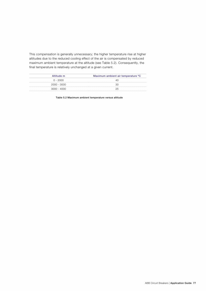
ABB Circuit Breakers | Application Guide 77
This compensation is generally unnecessary; the higher temperature rise at higher altitudes due to the reduced cooling effect of the air is compensated by reduced maximum ambient temperature at the altitude (see Table 5.2). Consequently, the final temperature is relatively unchanged at a given current.
Altitude m Maximum ambient air temperature ºC
0 - 2000 40
2000 - 3000 30
3000 - 4000 25
Table 5.2 Maximum ambient temperature versus altitude
78 Application Guide | ABB Circuit Breakers
6. Insulation requirements
This chapter presents the requirements on the circuit breaker to operate at its rated voltage and within its ratings of insulation data. Other factors which have influence on the insulation, such as ambient conditions, creepage distance and flash-over distance, are mentioned.
6.1 Insulation co-ordinationIEC defines insulation co-ordination as “the selection of the dielectric strength of equipment in relation to the voltages which can appear on the system for which the equipment is intended and taking into account the characteristics of the available protective devices.”) This means that circuit breakers and other electrical equipment must withstand the operational system voltage as well as the overvoltages occurring in the network. Therefore certain insulation requirements are specified for each level of system voltage. Voltage withstand requirements given in today’s standards are based on experience, calculations and statistics. The withstand capability has to be verified by type tests and routine tests in accordance with the relevant standards.
The overvoltages can be atmospheric discharges (lightning) and switching surges, or they can be temporary overvoltages at power frequency.
6.2 Overvoltages 6.2.1 Short-duration power frequency voltageUnder certain conditions, temporary overvoltages may occur in a power system. A typical reason is single-phase earth faults, which will lead to increased power frequency voltage on the healthy phases. The standard voltage for the temporary over-voltage is the short-duration power-frequency voltage, a normal alternating voltage with a frequency in the range of 48 to 62 Hz. It is normally referred to as the power-frequency voltage.
6.2.2 Lightning impulseLightning strokes, e.g. to an overhead line, will lead to overvoltages in the power system. The highest amplitudes that can occur depend on the dielectric withstand capability of the insulation and of the surge arresters in the system. Therefore there is a relationship between the rated voltage of the system and the lightning impulse amplitude specified by the standards.
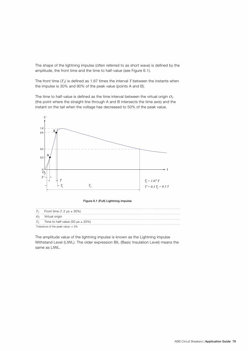
ABB Circuit Breakers | Application Guide 79
The shape of the lightning impulse (often referred to as short wave) is defined by the amplitude, the front time and the time to half-value (see Figure 6.1).
The front time (T1) is defined as 1.67 times the interval T between the instants when the impulse is 30% and 90% of the peak value (points A and B).
The time to half-value is defined as the time interval between the virtual origin O1 (the point where the straight line through A and B intersects the time axis) and the instant on the tail when the voltage has decreased to 50% of the peak value.
Figure 6.1 (Full) Lightning impulse
T1 Front time (1.2 µs ± 30%)
O1 Virtual origin
T2 Time to half-value (50 µs ± 20%)
Tolerance of the peak value: ± 3%
The amplitude value of the lightning impulse is known as the Lightning Impulse Withstand Level (LIWL). The older expression BIL (Basic Insulation Level) means the same as LIWL.
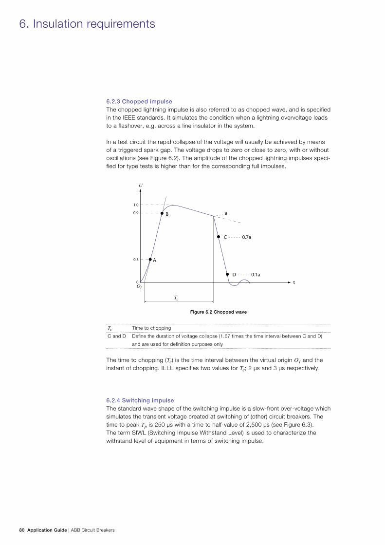
80 Application Guide | ABB Circuit Breakers
6. Insulation requirements
6.2.3 Chopped impulseThe chopped lightning impulse is also referred to as chopped wave, and is specified in the IEEE standards. It simulates the condition when a lightning overvoltage leads to a flashover, e.g. across a line insulator in the system.
In a test circuit the rapid collapse of the voltage will usually be achieved by means of a triggered spark gap. The voltage drops to zero or close to zero, with or without oscillations (see Figure 6.2). The amplitude of the chopped lightning impulses speci-fied for type tests is higher than for the corresponding full impulses.
Figure 6.2 Chopped wave
Tc Time to chopping
C and D Define the duration of voltage collapse (1.67 times the time interval between C and D)
and are used for definition purposes only
The time to chopping (Tc) is the time interval between the virtual origin O1 and the instant of chopping. IEEE specifies two values for Tc; 2 µs and 3 µs respectively.
6.2.4 Switching impulseThe standard wave shape of the switching impulse is a slow-front over-voltage which simulates the transient voltage created at switching of (other) circuit breakers. The time to peak Tp is 250 µs with a time to half-value of 2,500 µs (see Figure 6.3). The term SIWL (Switching Impulse Withstand Level) is used to characterize the withstand level of equipment in terms of switching impulse.
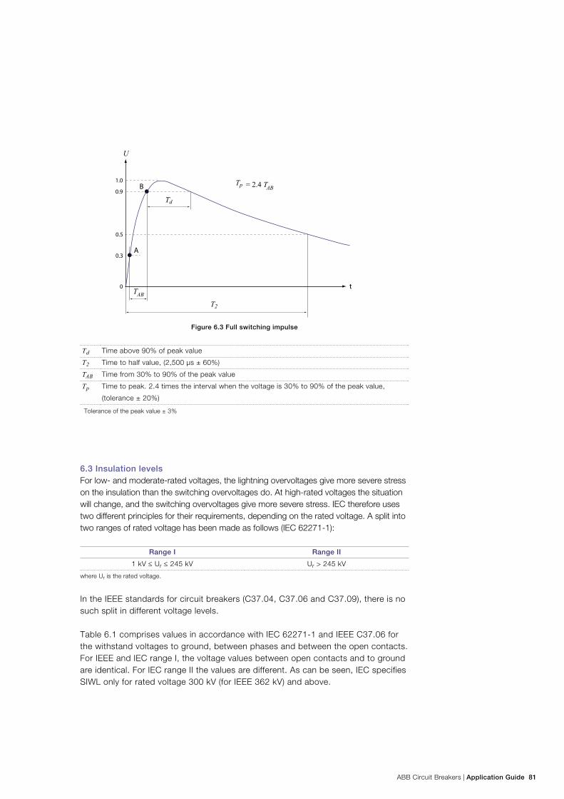
ABB Circuit Breakers | Application Guide 81
Figure 6.3 Full switching impulse
Td Time above 90% of peak value
T2 Time to half value, (2,500 µs ± 60%)
TAB Time from 30% to 90% of the peak value
Tp Time to peak. 2.4 times the interval when the voltage is 30% to 90% of the peak value,
(tolerance ± 20%)
Tolerance of the peak value ± 3%
6.3 Insulation levelsFor low- and moderate-rated voltages, the lightning overvoltages give more severe stress on the insulation than the switching overvoltages do. At high-rated voltages the situation will change, and the switching overvoltages give more severe stress. IEC therefore uses two different principles for their requirements, depending on the rated voltage. A split into two ranges of rated voltage has been made as follows (IEC 62271-1):
Range I Range II
1 kV ≤ Ur ≤ 245 kV Ur > 245 kV
where Ur is the rated voltage.
In the IEEE standards for circuit breakers (C37.04, C37.06 and C37.09), there is no such split in different voltage levels.
Table 6.1 comprises values in accordance with IEC 62271-1 and IEEE C37.06 for the withstand voltages to ground, between phases and between the open contacts. For IEEE and IEC range I, the voltage values between open contacts and to ground are identical. For IEC range II the values are different. As can be seen, IEC specifies SIWL only for rated voltage 300 kV (for IEEE 362 kV) and above.
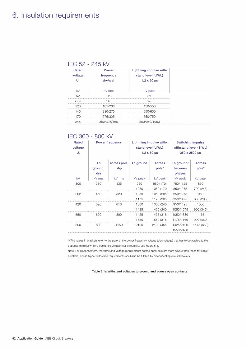
82 Application Guide | ABB Circuit Breakers
6. Insulation requirements
IEC 52 - 245 kVRated
voltage
Ur
kV
Power
frequency
dry/wet
kV rms
Lightning impulse with-
stand level (LIWL)
1.2 x 50 µs
kV peak
52 95 250
72.5 140 325
123 185/230 450/550
145 230/275 550/650
170 275/325 650/750
245 360/395/460 850/950/1050
IEC 300 - 800 kVRated
voltage
Ur
Power frequency Lightning impulse with-
stand level (LIWL)
1.2 x 50 µs
Switching impulse
withstand level (SIWL)
250 x 2500 µs
To
ground,
dry
Across pole,
dry
To ground Across
pole*
To ground/
between
phases
Across
pole*
kV kV rms kV rms kV peak kV peak kV peak kV peak
300 380 435 950
1050
950 (170)
1050 (170)
750/1125
850/1275
850
700 (245)
362 450 520 1050
1175
1050 (205)
1175 (205)
850/1275
950/1425
950
800 (295)
420 520 610 1300
1425
1300 (240)
1425 (240)
950/1425
1050/1575
1050
900 (345)
550 620 800 1425
1550
1425 (315)
1550 (315)
1050/1680
1175/1760
1175
900 (450)
800 830 1150 2100 2100 (455) 1425/2420
1550/2480
1175 (650)
*) The values in brackets refer to the peak of the power frequency voltage (bias voltage) that has to be applied to the
opposite terminal when a combined voltage test is required, see Figure 6.4.
Note: For disconnectors, the withstand voltage requirements across open pole are more severe than those for circuit
breakers. These higher withstand requirements shall also be fulfilled by disconnecting circuit breakers.
Table 6.1a Withstand voltages to ground and across open contacts
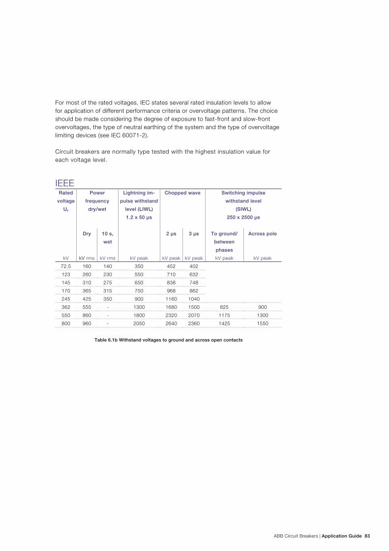
ABB Circuit Breakers | Application Guide 83
For most of the rated voltages, IEC states several rated insulation levels to allow for application of different performance criteria or overvoltage patterns. The choice should be made considering the degree of exposure to fast-front and slow-front overvoltages, the type of neutral earthing of the system and the type of overvoltage limiting devices (see IEC 60071-2).
Circuit breakers are normally type tested with the highest insulation value for each voltage level.
IEEE Rated
voltage
Ur
Power
frequency
dry/wet
Lightning im-
pulse withstand
level (LIWL)
1.2 x 50 µs
Chopped wave Switching impulse
withstand level
(SIWL)
250 x 2500 µs
Dry 10 s,
wet
2 µs 3 µs To ground/
between
phases
Across pole
kV kV rms kV rms kV peak kV peak kV peak kV peak kV peak
72.5 160 140 350 452 402
123 260 230 550 710 632
145 310 275 650 838 748
170 365 315 750 968 862
245 425 350 900 1160 1040
362 555 - 1300 1680 1500 825 900
550 860 - 1800 2320 2070 1175 1300
800 960 - 2050 2640 2360 1425 1550
Table 6.1b Withstand voltages to ground and across open contacts
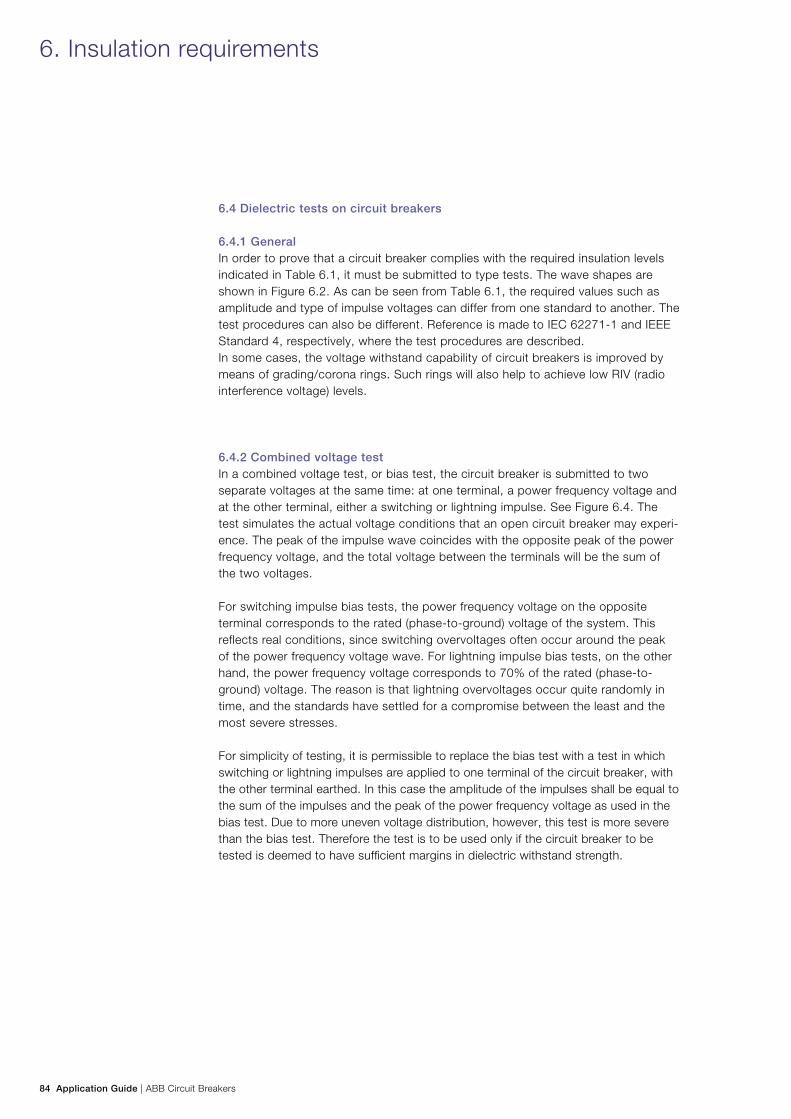
84 Application Guide | ABB Circuit Breakers
6. Insulation requirements
6.4 Dielectric tests on circuit breakers
6.4.1 GeneralIn order to prove that a circuit breaker complies with the required insulation levels indicated in Table 6.1, it must be submitted to type tests. The wave shapes are shown in Figure 6.2. As can be seen from Table 6.1, the required values such as amplitude and type of impulse voltages can differ from one standard to another. The test procedures can also be different. Reference is made to IEC 62271-1 and IEEE Standard 4, respectively, where the test procedures are described. In some cases, the voltage withstand capability of circuit breakers is improved by means of grading/corona rings. Such rings will also help to achieve low RIV (radio interference voltage) levels.
6.4.2 Combined voltage testIn a combined voltage test, or bias test, the circuit breaker is submitted to two separate voltages at the same time: at one terminal, a power frequency voltage and at the other terminal, either a switching or lightning impulse. See Figure 6.4. The test simulates the actual voltage conditions that an open circuit breaker may experi-ence. The peak of the impulse wave coincides with the opposite peak of the power frequency voltage, and the total voltage between the terminals will be the sum of the two voltages.
For switching impulse bias tests, the power frequency voltage on the opposite terminal corresponds to the rated (phase-to-ground) voltage of the system. This reflects real conditions, since switching overvoltages often occur around the peak of the power frequency voltage wave. For lightning impulse bias tests, on the other hand, the power frequency voltage corresponds to 70% of the rated (phase-to-ground) voltage. The reason is that lightning overvoltages occur quite randomly in time, and the standards have settled for a compromise between the least and the most severe stresses.
For simplicity of testing, it is permissible to replace the bias test with a test in which switching or lightning impulses are applied to one terminal of the circuit breaker, with the other terminal earthed. In this case the amplitude of the impulses shall be equal to the sum of the impulses and the peak of the power frequency voltage as used in the bias test. Due to more uneven voltage distribution, however, this test is more severe than the bias test. Therefore the test is to be used only if the circuit breaker to be tested is deemed to have sufficient margins in dielectric withstand strength.
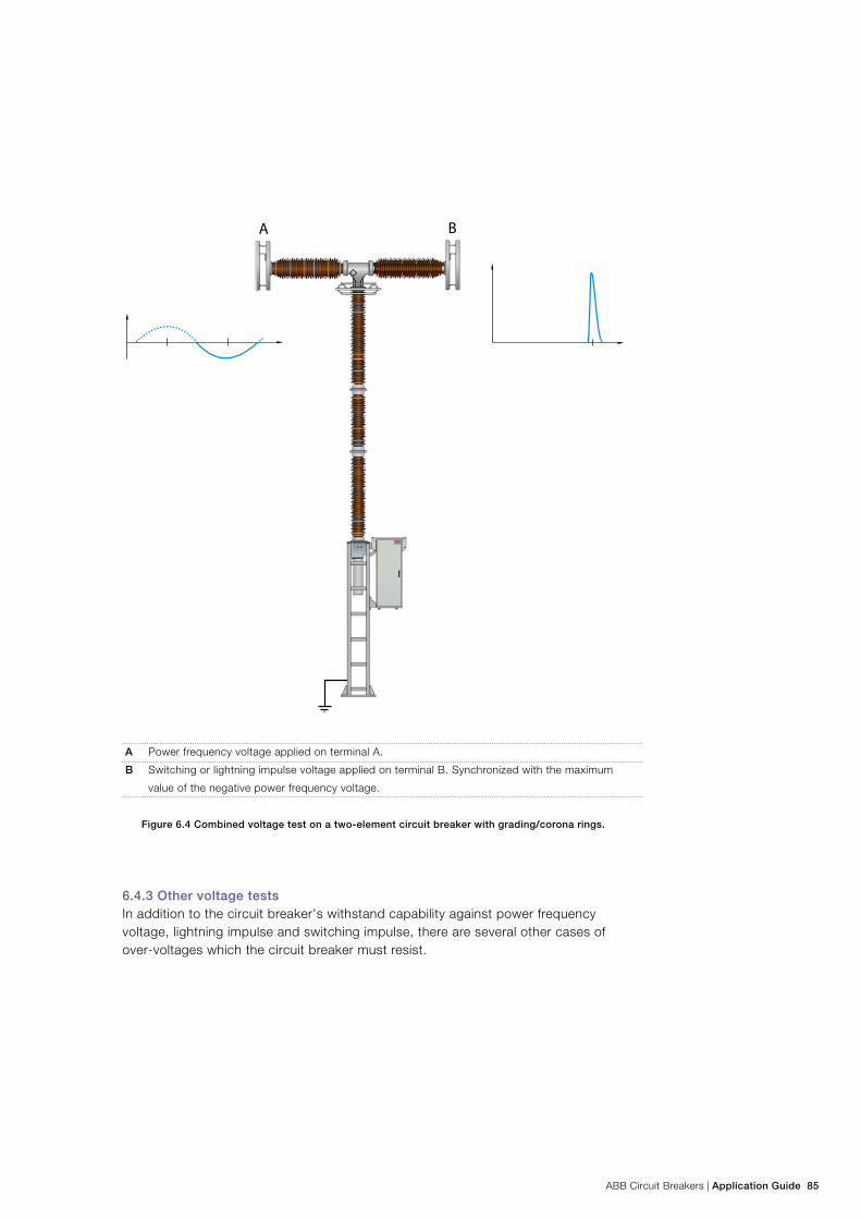
ABB Circuit Breakers | Application Guide 85
ON
A B
A Power frequency voltage applied on terminal A.
B Switching or lightning impulse voltage applied on terminal B. Synchronized with the maximum
value of the negative power frequency voltage.
Figure 6.4 Combined voltage test on a two-element circuit breaker with grading/corona rings.
6.4.3 Other voltage testsIn addition to the circuit breaker’s withstand capability against power frequency voltage, lightning impulse and switching impulse, there are several other cases of over-voltages which the circuit breaker must resist.
86 Application Guide | ABB Circuit Breakers
6.4.3.1 RIV (Radio Interference Voltage) tests As with all other types of HV equipment, an energized circuit breaker may generate radio interference voltages, RIV. These are high-frequency disturbances, typically caused by electrical discharges (corona) from sharp edges of terminals, etc. IEC 62271-100 specifies that RIV tests are applicable to circuit breakers having a rated voltage of 123 kV and above. The required test procedure is in accordance with CISPR Publication 16 and is described in detail in IEC 62271-1. The RIV level shall not exceed 2,500 µV at a test voltage 10% above the rated phase-to-ground voltage. The test voltage is applied for 5 minutes and the measurement is per-formed at a frequency of 500 - 2,000 kHz.
The corresponding values according to IEEE C37.09 are given in NEMA Publica-tion 107. The test voltage is 1.05 times the rated phase-to-ground voltage. The allowable values of the interference level are given in NEMA Standards Publication SG 4, Table 4-1. The highest allowable interference level from 123 kV and up-wards is 2,500 µV at 1,000 kHz.
6.4.3.2 Partial discharge testA partial discharge tests will reveal the same kind of disturbances as an RIV test, but is mainly used for detection of weaknesses in the internal insulation of compo-nents such as bushings and grading capacitors. This test is normally not required for live tank circuit breakers. IEC 62271-100 states that the test should be performed only if the circuit breaker uses components for which a rel-evant standard exists (for example bushings). For the sake of interest, it is worth noting that the test is carried out with a test voltage 10% above the rated phase-ground voltage. The partial discharge should not exceed 5 pC.
6.4.3.3 Pollution testThe intention with this artificial test is to simulate the operating conditions at a certain degree of pollution (see Section 6.7.1). However, in most cases this test is not required. If the creepage distance complies with the requirement mentioned in Table 6.3, the artificial pollution test is not necessary (see IEC 60507).
The test procedure and requirements are described in IEC 60060-1 and IEC 60507 respectively. In short, the circuit breaker covered by a layer of salt solution corre-sponding to the specified contamination is submitted to a test voltage equal to its rated phase-to-ground voltage.
6.4.3.4 Tests on low-voltage circuitsEven the low-voltage circuits (control, motor, heater, etc.) must be submitted to voltage tests. The requirement according to IEC 62271-1 is:
− Power frequency voltage: 2 kV rms 1 min.
6. Insulation requirements
ABB Circuit Breakers | Application Guide 87
6.5 Atmospheric correction factorThe withstand capability of external insulation is affected by the atmospheric pres-sure, temperature and humidity. The withstand values given in Table 6.1 are valid for standard atmospheric conditions, which are defined as:
− temperature t0 = 20 ºC − pressure b0 = 101,3 kPa (older expression 1013 mbar) − humidity h0 = 11 g/m3
If the atmospheric conditions at the testing site deviate from the standard, correc-tion factors may be applied for air density and humidity. The voltage applied during a test on external insulation is then determined by multiplying the specified test volt-age by the atmospheric correction factor, which is defined in IEC 60060-1: Kt = k1 k2 where
k1 air density correction factor
b atmospheric pressure at test occasion
t temperature at test occasion
m exponent defined in IEC 60060-1
k2 humidity correction factor
k factor depending on the type of test voltage
w exponent defined in IEC 60060-1
A test report on dielectric tests normally states absolute voltages in accordance with the standard requirements. To obtain the actual stresses on the circuit break-ers, external insulation should be applied during the test correction. The maximum allowable correction factor for any test is 5%; the values given in the report may be divided by max 1.05 or 0.95 (whichever is applicable) in order to obtain the correct impulse level.
Example: For a test on a 245 kV circuit breaker, the test voltage used at the test was 1050 kV. The correction factor Kt during the test was 0.95 or lower, but was not applied. This means that the external insulation was stressed at a voltage of at least 1050/0.95 = 1105 kV. This knowledge can sometimes be used for installations at high altitude, or when a customer requires insulation levels slightly higher than the standardized values. RIV tests and low-voltage tests are not affected by the atmo-spheric correction factor.
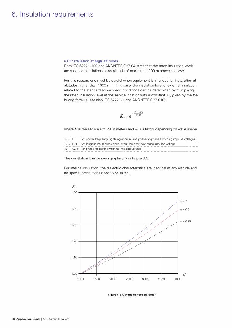
88 Application Guide | ABB Circuit Breakers
6.6 Installation at high altitudes Both IEC 62271-100 and ANSI/IEEE C37.04 state that the rated insulation levels are valid for installations at an altitude of maximum 1000 m above sea level.
For this reason, one must be careful when equipment is intended for installation at altitudes higher than 1000 m. In this case, the insulation level of external insulation related to the standard atmospheric conditions can be determined by multiplying the rated insulation level at the service location with a constant Ka, given by the fol-lowing formula (see also IEC 62271-1 and ANSI/IEEE C37.010):
where H is the service altitude in meters and m is a factor depending on wave shape
m = 1 for power frequency, lightning impulse and phase-to-phase switching impulse voltages
m = 0.9 for longitudinal (across open circuit breaker) switching impulse voltage
m = 0.75 for phase-to-earth switching impulse voltage
The correlation can be seen graphically in Figure 6.5.
For internal insulation, the dielectric characteristics are identical at any altitude and no special precautions need to be taken.
Figure 6.5 Altitude correction factor
6. Insulation requirements
1.50
1.40
1.30
1.20
1.10
1.00
1000 1500 2000 2500 3000 3500 4000
m = 1
m = 0.9
m = 0.75
ABB Circuit Breakers | Application Guide 89
Example:A 170 kV circuit breaker is going to be installed at an altitude of 2,200 m above sea level. The customer specification calls for an insulation level of 750 kV at site level.
Which circuit breaker will fulfill the requirements?
The required insulation level at sea level will be obtained using the formula for Ka given above, and the following considerations:
− For lightning impulse and power frequency m = 1, hence Ka = 1.16. This means that the circuit breaker needs to be tested at sea level with a voltage of 750 · Ka = 870 kV.
− The nearest standardized impulse voltage is 1050 kV, which belongs to a system voltage of 245 kV.
− The requirement for the power frequency withstand at sea level is 377 kV (325 · 1.16) (dry and wet). This is covered by the requirements, (460 kV) for a 245 kV circuit breaker.
Conclusion: The circuit breaker fulfilling the requirements for the high altitude will be a breaker with insulation levels belonging to a system voltage of 245 kV.
6.7 Environmental effects and insulator shapes
6.7.1 Creepage distance and pollutionDepending on the site conditions, insulator surfaces of outdoor equipment will sooner or later collect deposits. When the deposits mainly consist of salt, which is normal in coastal regions, the surface resistance of the insulator decreases. The insulation withstand capability of the insulator is therefore essentially reduced, especially in periods of dew or fog. Heating due to the leakage current resulting in uneven drying of the surface can cause partial discharges (streamers), which might lead to a disruptive discharge across the insulator (flashover).
During periods of rain, the insulators are naturally washed. Substations in, for example, coastal areas often have routines established to prevent the build up of heavy deposits of salt on the insulators. These routines range from manual cleaning to fully automatic cleaning.
In areas with heavy pollution, composite insulators with silicone sheds can be used to minimize or even eliminate the need for cleaning. Due to the chemical nature of silicone rubber, the insulator surface is hydrophobic (non-wetting). Water on the sur-face stays as droplets and does not form a continuous water film. This means that any leakage current along the insulator surface is strongly suppressed.
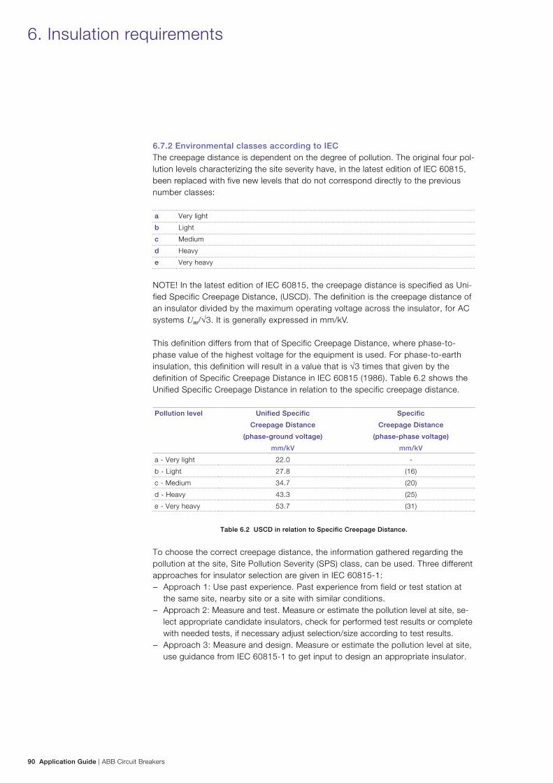
90 Application Guide | ABB Circuit Breakers
6. Insulation requirements
6.7.2 Environmental classes according to IECThe creepage distance is dependent on the degree of pollution. The original four pol-lution levels characterizing the site severity have, in the latest edition of IEC 60815, been replaced with five new levels that do not correspond directly to the previous number classes:
a Very light
b Light
c Medium
d Heavy
e Very heavy
NOTE! In the latest edition of IEC 60815, the creepage distance is specified as Uni-fied Specific Creepage Distance, (USCD). The definition is the creepage distance of an insulator divided by the maximum operating voltage across the insulator, for AC systems Um/√3. It is generally expressed in mm/kV.
This definition differs from that of Specific Creepage Distance, where phase-to-phase value of the highest voltage for the equipment is used. For phase-to-earth insulation, this definition will result in a value that is √3 times that given by the definition of Specific Creepage Distance in IEC 60815 (1986). Table 6.2 shows the Unified Specific Creepage Distance in relation to the specific creepage distance.
Pollution level Unified Specific
Creepage Distance
(phase-ground voltage)
Specific
Creepage Distance
(phase-phase voltage)
mm/kV mm/kV
a - Very light 22.0 -
b - Light 27.8 (16)
c - Medium 34.7 (20)
d - Heavy 43.3 (25)
e - Very heavy 53.7 (31)
Table 6.2 USCD in relation to Specific Creepage Distance.
To choose the correct creepage distance, the information gathered regarding the pollution at the site, Site Pollution Severity (SPS) class, can be used. Three different approaches for insulator selection are given in IEC 60815-1:
− Approach 1: Use past experience. Past experience from field or test station at the same site, nearby site or a site with similar conditions.
− Approach 2: Measure and test. Measure or estimate the pollution level at site, se-lect appropriate candidate insulators, check for performed test results or complete with needed tests, if necessary adjust selection/size according to test results.
− Approach 3: Measure and design. Measure or estimate the pollution level at site, use guidance from IEC 60815-1 to get input to design an appropriate insulator.
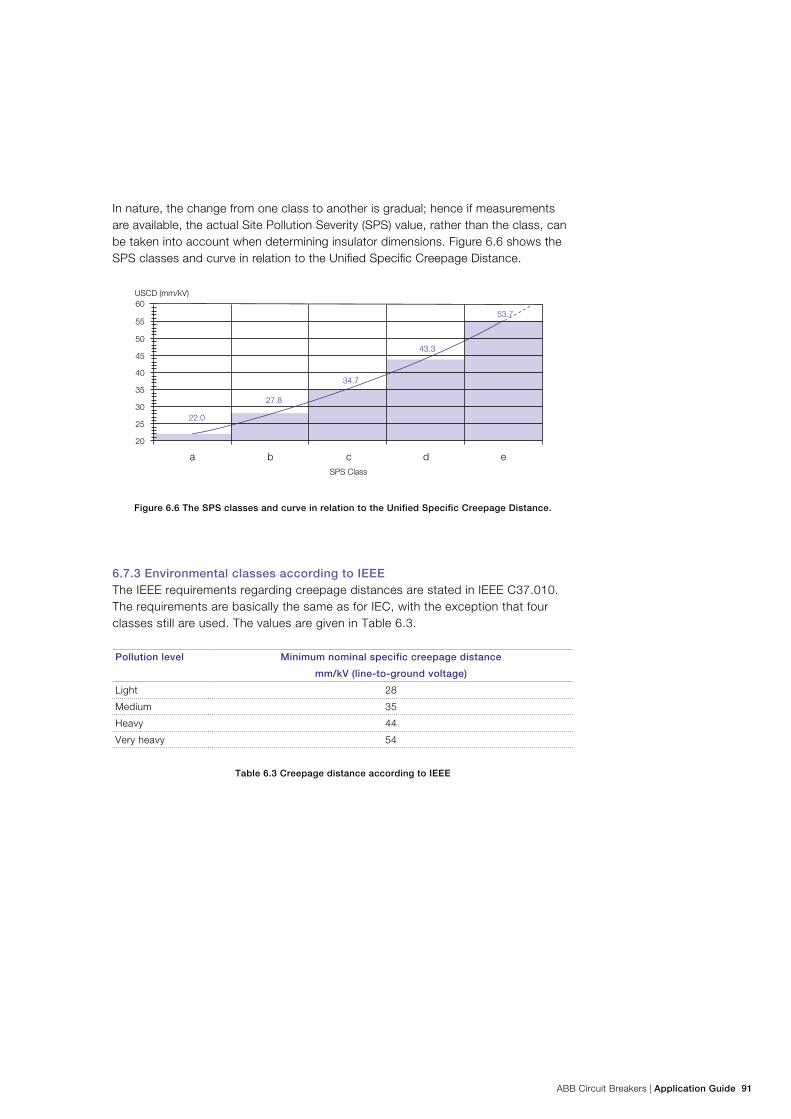
ABB Circuit Breakers | Application Guide 91
In nature, the change from one class to another is gradual; hence if measurements are available, the actual Site Pollution Severity (SPS) value, rather than the class, can be taken into account when determining insulator dimensions. Figure 6.6 shows the SPS classes and curve in relation to the Unified Specific Creepage Distance.
Figure 6.6 The SPS classes and curve in relation to the Unified Specific Creepage Distance.
6.7.3 Environmental classes according to IEEE The IEEE requirements regarding creepage distances are stated in IEEE C37.010. The requirements are basically the same as for IEC, with the exception that four classes still are used. The values are given in Table 6.3.
Pollution level Minimum nominal specific creepage distance
mm/kV (line-to-ground voltage)
Light 28
Medium 35
Heavy 44
Very heavy 54
Table 6.3 Creepage distance according to IEEE
20
25
30
35
40
45
50
55
60
a b c d e
22.0
27.8
34.7
43.3
53.7
USCD (mm/kV)
SPS Class
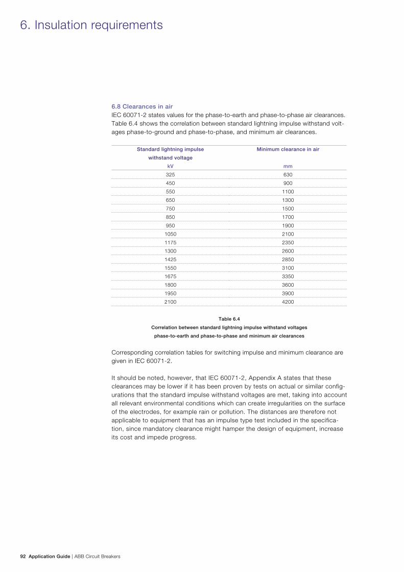
92 Application Guide | ABB Circuit Breakers
6.8 Clearances in air IEC 60071-2 states values for the phase-to-earth and phase-to-phase air clearances. Table 6.4 shows the correlation between standard lightning impulse withstand volt-ages phase-to-ground and phase-to-phase, and minimum air clearances.
Standard lightning impulse
withstand voltage
Minimum clearance in air
kV mm
325 630
450 900
550 1100
650 1300
750 1500
850 1700
950 1900
1050 2100
1175 2350
1300 2600
1425 2850
1550 3100
1675 3350
1800 3600
1950 3900
2100 4200
Table 6.4
Correlation between standard lightning impulse withstand voltages
phase-to-earth and phase-to-phase and minimum air clearances
Corresponding correlation tables for switching impulse and minimum clearance are given in IEC 60071-2.
It should be noted, however, that IEC 60071-2, Appendix A states that these clearances may be lower if it has been proven by tests on actual or similar config-urations that the standard impulse withstand voltages are met, taking into account all relevant environmental conditions which can create irregularities on the surface of the electrodes, for example rain or pollution. The distances are therefore not applicable to equipment that has an impulse type test included in the specifica-tion, since mandatory clearance might hamper the design of equipment, increase its cost and impede progress.
6. Insulation requirements
ABB Circuit Breakers | Application Guide 93
6.9 Insulating material Porcelain is the traditional material for outdoor insulation, but in recent years several types of composite material have become more and more common.
ABB can now deliver composite insulators with silicone rubber (SIR) sheds for all high-voltage equipment. (See our Buyer’s Guide for Live Tank Circuit Breakers, chapter on Composite Insulators).
Several field tests indicate that pollution performance and the short-term and long-term hydrophobicity characteristics of composite insulators with silicone rubber are better than those of porcelain insulators.
Considering both aging and pollution performance, in most cases it is possible to reduce creepage distance in coastal areas by a minimum one pollution level accord-ing to ABB experiences when composite insulators are used.
94 Application Guide | ABB Circuit Breakers
7. Application
7.1 Transmission line circuit breakersApproximately 50% of all circuit breakers installed are used for transmission line appli-cation, i.e. they are directly connected to a transmission line. Transmission line circuit breakers normally switch currents associated with the following switching cases:
− Terminal faults (see 3.2) − Short-line faults (see 3.3) − Out-of-phase faults (see 3.5) − No-load transmission line (see 3.6)
Normally rapid auto-reclosing is specified for line circuit breakers. The operating duty cycle in accordance with IEC 62271-100 is:
O - 0.3 s - CO - 3 min - CO
Normally the time 3 minutes between the two close-open operations is valid, but as an alternative IEC specifies that the time values 15 s or 1 min can also be used. The dead time of 0.3 s is based on the recovery time of the air surrounding an external arc in the system (i.e. a short-circuit). The time of 3 min is the time needed for the operating mechanism to restore its power after a O - 0.3 s - CO. Modern spring and hydraulic operating mechanisms do not need 3 min to restore their power. However, shortening of the restore time and expanding the duty cycle beyond the standard duty cycle should be approached with caution.
7.1.1 Faults on overhead lines Faults can appear anywhere in the network, at any given time. They can be single-phase, two-phase or three-phase. In almost all cases faults include earth. That fact is also the basis of the rating used in IEC 62271-100.
Most faults occur on transmission lines, which means that transmission line circuit breakers are exposed to wear caused by short-circuits. However, the average fre-quency of occurrence of short-circuits is low, and the magnitude is normally below 60% of the capability of the circuit breaker. Extended electrical endurance is not required for transmission line circuit breakers.
There can be several causes for faults on a transmission line:a. Lightning: One of the most common causes. A lightning flash can hit the tower
and cause a backflash across one of the string insulators. Another cause can be a direct flash on one of the phase conductors. This may happen when the trans-mission line is not protected by shield wire or after a shield wire failure. One particular aspect of lightning is the occurrence of multiple stroke lightning flashes. Although their occurrence has a low probability, they need to be consid-ered. When a circuit breaker is in the process of interrupting a short-circuit that is the result of a lightning flash and there is a second or third stroke, the opening contact gap is exposed to a voltage wave with a steep front. This voltage may exceed the dielectric withstand of the contact gap and a flashover may occur
ABB Circuit Breakers | Application Guide 95
across the contact gap. If multiple stroke lightning flashes are expected, the circuit breaker should be protected by means of surge arresters, located on the line side of the circuit breaker. Such surge arresters will also protect other HV equipment on the line side, such as voltage transformers.
b. Wind: During periods of strong winds in combination with an unfavorable direc-tion, galloping of lines my occur. Under those conditions two phase conductors may touch, causing a two-phase fault.
c. Nature: Trees may fall on a line or sagging of the phase conductors, causing flashovers to trees located under the mid span during extremely warm weather.
d. Bushfires: Bushfires may be caused by lightning or human intervention. When a firestorm passes under a transmission line, the hot air may cause phase-to-phase or phase-to-ground flashovers.
7.1.2 Switching of no-load transmission lines
7.1.2.1 Voltage factorThe switching of no-load transmission lines is treated in Section 3.6. Section 3.6 also contains information regarding the capacitive voltage factor kc to be used when performing single-phase tests as a substitute for three-phase tests. The following applies for transmission lines during normal service conditions (i.e. without faults present): kc = 1.2 for transmission lines in effectively earthed systems
kc = 1.4 for transmission line in non-effectively earthed systems
In effectively earthed systems in the presence of single or two-phase earth faults: kc = 1.4 applies
There are special cases, for example with multiple overhead line constructions having parallel circuits, where due to the capacitive coupling between the systems, a voltage factor of 1.2 is not sufficient. For such systems a voltage factor of 1.3 is considered sufficient.
7.1.2.2 Line charging currentThe preferred values of line charging current given in IEC 62271-100 are covering applications where the line length does not exceed 400 km at 362 kV to 550 kV. For longer lines, the current is higher. This does not pose a problem for modern SF6 circuit breakers.
96 Application Guide | ABB Circuit Breakers
7.1.2.3 ReclosingIn the case of a fault on the transmission line, the circuit breakers at both ends of the line are opened and one of the two circuit breakers interrupts the fault. Provided that the circuit breakers are single-pole operated, the protection system may be arranged to open only the faulted phase(s), and leave the healthy phase(s) unaffected. As a result, the line will still have some transmission capability left. This will help to maintain stability in large, heavily loaded transmission systems. If all three poles of the circuit breaker are opened, the poles not interrupting the fault are switching a no-load transmission line. When the circuit breaker recloses, the poles switching the no-load transmission line are now energizing the transmis-sion line. As a worst case, this energizing may occur when the trapped charge on the line is at opposite polarity. The poles energizing the faulted line are energiz-ing a transmission line without trapped charge. One way of limiting the voltage transients associated with the energizing of no-load transmission lines is by using preinsertion resistors. The value of the resistance is in the order of the surge im-pedance of the line (a typical resistance value is 400 Ω) and the preinsertion time 8 – 12 ms to guarantee that the voltage wave has traveled out and back a couple of times before the main contacts close.
Another way of limiting the voltage transients is using controlled switching. This is described in ABB Controlled Switching, Buyer’s and Application Guide.
7.1.2.4 Shunt compensated transmission linesLong transmission lines may be equipped with shunt compensation (directly con-nected shunt reactors) that is used to compensate the reactive power generation in times when the transmission line is lightly loaded. The presence of shunt reactors will result in less severe interrupting conditions for the circuit breaker when switch-ing the no-load transmission line current. This is due to the fact that the load side of the circuit breaker no longer sees a dc voltage due to trapped charge, but a rather low frequency ac voltage, the frequency depending on the degree of compensation.
7.1.2.5 Series compensated transmission linesTo increase the transmitted power of long transmission lines, series compensation (series capacitor) may be used. The presence of series capacitors may increase the severity of the TRV imposed on the line circuit breakers during fault interruption. Un-der special fault conditions, delayed current zeros may occur and the circuit breaker may need to be adapted for this special duty.
7.1.3 ClassificationThe normal operating frequency of transmission line circuit breakers is low, perhaps a few times per year. That means that a class M1 circuit breaker is sufficient. Only in rare cases where frequent switching of transmission lines is anticipated is a class M2 circuit breaker recommended.
7. Application
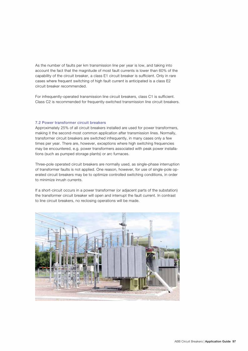
ABB Circuit Breakers | Application Guide 97
As the number of faults per km transmission line per year is low, and taking into account the fact that the magnitude of most fault currents is lower than 60% of the capability of the circuit breaker, a class E1 circuit breaker is sufficient. Only in rare cases where frequent switching of high fault current is anticipated is a class E2 circuit breaker recommended.
For infrequently-operated transmission line circuit breakers, class C1 is sufficient. Class C2 is recommended for frequently-switched transmission line circuit breakers.
7.2 Power transformer circuit breakersApproximately 25% of all circuit breakers installed are used for power transformers, making it the second-most common application after transmission lines. Normally, transformer circuit breakers are switched infrequently, in many cases only a few times per year. There are, however, exceptions where high switching frequencies may be encountered, e.g. power transformers associated with peak power installa-tions (such as pumped storage plants) or arc furnaces.
Three-pole operated circuit breakers are normally used, as single-phase interruption of transformer faults is not applied. One reason, however, for use of single-pole op-erated circuit breakers may be to optimize controlled switching conditions, in order to minimize inrush currents.
If a short-circuit occurs in a power transformer (or adjacent parts of the substation) the transformer circuit breaker will open and interrupt the fault current. In contrast to line circuit breakers, no reclosing operations will be made.
98 Application Guide | ABB Circuit Breakers
An extreme case may occur for circuit breakers close to centers of generation, typically placed on the high-voltage side of large generator step-up (GSU) trans-formers. In this location the ac component of the short-circuit current may decrease more quickly than in the normal case. The short-circuit current may then not have a current zero for a number of cycles, preventing interruption of the current. In such circumstances the duty of the circuit breaker can be eased, for example, by delay-ing its opening. Alternatively, it may be proven by tests or calculations that the arc voltage of the circuit breaker is high enough to damp the dc component of the cur-rent so much that a current zero will occur.
7.2.1 Asymmetry and dc time constant Power transformers generally have higher X/R ratios than lines and cables. There-fore, in situations where the impedances of power transformers have a dominating influence on the short circuit current level, the dc time constant may be higher than the standard value 45 ms. A typical case is a busbar of a substation with power infeed solely through power transformers. In most cases, however, this situation is also associated with short-circuit current levels far below the rated short-circuit cur-rent of the associated circuit breakers. Therefore, the stresses will still be adequate-ly covered by circuit breakers with standard time constant 45 ms. An exception to this general situation may occur in medium-voltage networks (≤52 kV), where the infeed through power transformers may approach the rated short circuit current of the circuit breakers. For this situation an alternative time constant 120 ms is speci-fied in the IEC standards.
An extreme case may occur for circuit breakers close to centers of generation, typically placed on the high-voltage side of large generator step-up (GSU) trans-formers. In this location the ac component of the short-circuit current may decrease more quickly than in the normal case. The short-circuit current may then not have a current zero for a number of cycles, preventing interruption of the current. In such circumstances the duty of the circuit breaker can be eased, for example, by delay-ing its opening. Alternatively, it may be proven by tests or calculations that the arc voltage of the circuit breaker is high enough to damp the dc component of the cur-rent so much that a current zero will occur.
7.2.2 No-load switching conditionsWhen a power transformer is energized by closing of the circuit breaker, quite severe inrush currents may occur. The magnitude will depend on the point-on-wave energizing instant and on the amount of residual flux in the transformer core. It is often important to limit the inrush current magnitude, and one efficient method to do that is by controlled switching of the circuit breaker. Refer to ABB Controlled Switching, Buyer’s and Application Guide for further information on this subject.
Interruption of the no-load current of a power transformer is a case of interrup-tion of low inductive currents. Due to the strong damping of the voltage transients resulting from interruption, this is generally regarded as an easy switching case. See also Section 3.7.2.
7. Application
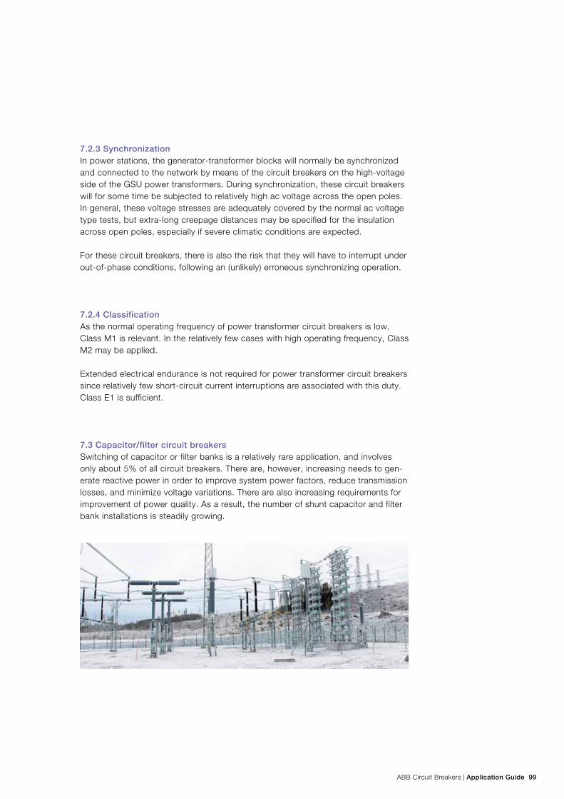
ABB Circuit Breakers | Application Guide 99
7.2.3 SynchronizationIn power stations, the generator-transformer blocks will normally be synchronized and connected to the network by means of the circuit breakers on the high-voltage side of the GSU power transformers. During synchronization, these circuit breakers will for some time be subjected to relatively high ac voltage across the open poles. In general, these voltage stresses are adequately covered by the normal ac voltage type tests, but extra-long creepage distances may be specified for the insulation across open poles, especially if severe climatic conditions are expected.
For these circuit breakers, there is also the risk that they will have to interrupt under out-of-phase conditions, following an (unlikely) erroneous synchronizing operation.
7.2.4 ClassificationAs the normal operating frequency of power transformer circuit breakers is low, Class M1 is relevant. In the relatively few cases with high operating frequency, Class M2 may be applied.
Extended electrical endurance is not required for power transformer circuit breakers since relatively few short-circuit current interruptions are associated with this duty. Class E1 is sufficient.
7.3 Capacitor/filter circuit breakersSwitching of capacitor or filter banks is a relatively rare application, and involves only about 5% of all circuit breakers. There are, however, increasing needs to gen-erate reactive power in order to improve system power factors, reduce transmission losses, and minimize voltage variations. There are also increasing requirements for improvement of power quality. As a result, the number of shunt capacitor and filter bank installations is steadily growing.
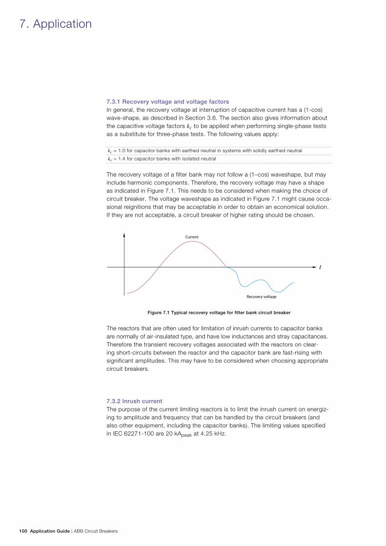
100 Application Guide | ABB Circuit Breakers
7.3.1 Recovery voltage and voltage factorsIn general, the recovery voltage at interruption of capacitive current has a (1-cos) wave-shape, as described in Section 3.6. The section also gives information about the capacitive voltage factors kc to be applied when performing single-phase tests as a substitute for three-phase tests. The following values apply: kc = 1.0 for capacitor banks with earthed neutral in systems with solidly earthed neutral
kc = 1.4 for capacitor banks with isolated neutral
The recovery voltage of a filter bank may not follow a (1–cos) waveshape, but may include harmonic components. Therefore, the recovery voltage may have a shape as indicated in Figure 7.1. This needs to be considered when making the choice of circuit breaker. The voltage waveshape as indicated in Figure 7.1 might cause occa-sional reignitions that may be acceptable in order to obtain an economical solution. If they are not acceptable, a circuit breaker of higher rating should be chosen.
Figure 7.1 Typical recovery voltage for filter bank circuit breaker
The reactors that are often used for limitation of inrush currents to capacitor banks are normally of air-insulated type, and have low inductances and stray capacitances. Therefore the transient recovery voltages associated with the reactors on clear-ing short-circuits between the reactor and the capacitor bank are fast-rising with significant amplitudes. This may have to be considered when choosing appropriate circuit breakers.
7.3.2 Inrush currentThe purpose of the current limiting reactors is to limit the inrush current on energiz-ing to amplitude and frequency that can be handled by the circuit breakers (and also other equipment, including the capacitor banks). The limiting values specified in IEC 62271-100 are 20 kApeak at 4.25 kHz.
7. Application
ABB Circuit Breakers | Application Guide 101
If a fault (short-circuit) occurs on the network in the vicinity of a capacitor bank, there will be outrush current flowing from the capacitor bank to the fault, of simi-lar magnitude and frequency as the inrush current. Such outrush current needs to be considered for all other circuit breakers connected to the same busbar as the capacitor bank(s).
Controlled switching is an efficient method for limitation of inrush currents at energizing, making the current limiting reactors superfluous. However, since the outrush currents are not related to any switching action of the capacitor bank circuit breaker, they are not affected by controlled switching schemes. For this reason cur-rent limiting reactors are often used, even when controlled switching is applied.
7.3.3 Rating and classificationThe network frequency has a major influence on the (1-cos) recovery voltage, and therefore on the risk of restrikes. 60 Hz applications are considerably more severe than 50 Hz applications.
The standard value of rated normal current for capacitor bank circuit breakers is 400 A. Higher values than 400 A do not pose a problem for modern circuit breakers.
Capacitor banks and filters provide a low-impedance path for the flow of harmonic currents, and therefore the power frequency current is normally modified to include the effect of the harmonics. A multiplier of 1.1 is generally used for a solidly earthed neutral bank and 1.05 for isolated neutral.
Circuit breakers for capacitor banks and filters are often switched regularly, e.g. on a daily basis. This means that the circuit breaker will have to cope with many opera-tions, and Class M2 and C2 are recommended. The expected number of short-cir-cuit interruptions is low, and electrical endurance class E1 is generally appropriate.
7.4 Shunt reactor circuit breakersFrom a system point of view, an overhead transmission line conducting low current will behave as a capacitive load, and generate reactive power. For networks with long EHV (Extra High Voltage > 245 kV) transmission lines the result may be unac-ceptably high system voltages and power losses. In order to avoid this situation, shunt reactors are often used in such systems. The shunt reactors will consume re-active power and thereby counteract the effect of the lightly loaded overhead lines. In large systems the optimal solution is often some permanently connected shunt reactors, together with some shunt reactors that are energized only during periods with low active power flow in the system (typically night time and weekends).
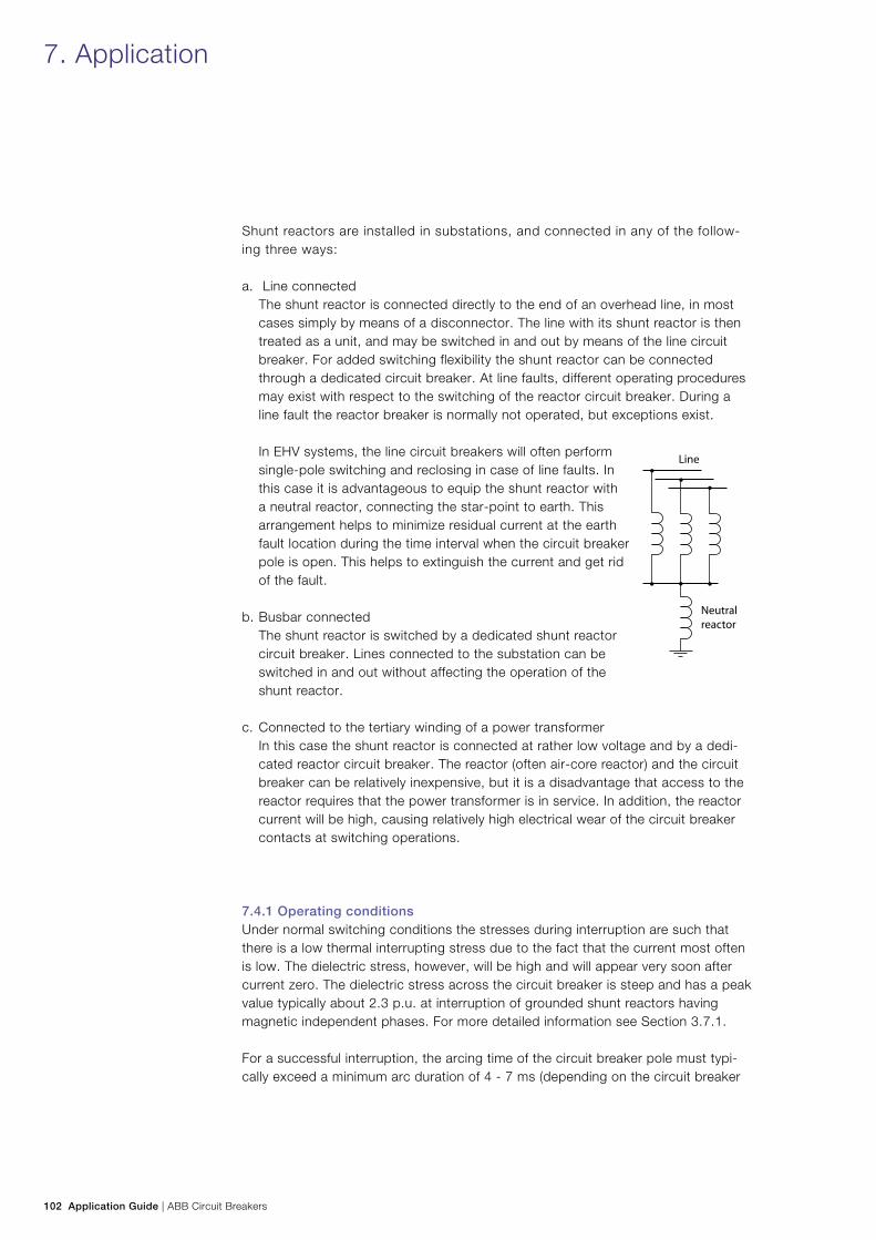
102 Application Guide | ABB Circuit Breakers
7. Application
Shunt reactors are installed in substations, and connected in any of the follow-ing three ways:
a. Line connected The shunt reactor is connected directly to the end of an overhead line, in most cases simply by means of a disconnector. The line with its shunt reactor is then treated as a unit, and may be switched in and out by means of the line circuit breaker. For added switching flexibility the shunt reactor can be connected through a dedicated circuit breaker. At line faults, different operating procedures may exist with respect to the switching of the reactor circuit breaker. During a line fault the reactor breaker is normally not operated, but exceptions exist. In EHV systems, the line circuit breakers will often perform single-pole switching and reclosing in case of line faults. In this case it is advantageous to equip the shunt reactor with a neutral reactor, connecting the star-point to earth. This arrangement helps to minimize residual current at the earth fault location during the time interval when the circuit breaker pole is open. This helps to extinguish the current and get rid of the fault.
b. Busbar connected The shunt reactor is switched by a dedicated shunt reactor circuit breaker. Lines connected to the substation can be switched in and out without affecting the operation of the shunt reactor.
c. Connected to the tertiary winding of a power transformer In this case the shunt reactor is connected at rather low voltage and by a dedi-cated reactor circuit breaker. The reactor (often air-core reactor) and the circuit breaker can be relatively inexpensive, but it is a disadvantage that access to the reactor requires that the power transformer is in service. In addition, the reactor current will be high, causing relatively high electrical wear of the circuit breaker contacts at switching operations.
7.4.1 Operating conditionsUnder normal switching conditions the stresses during interruption are such that there is a low thermal interrupting stress due to the fact that the current most often is low. The dielectric stress, however, will be high and will appear very soon after current zero. The dielectric stress across the circuit breaker is steep and has a peak value typically about 2.3 p.u. at interruption of grounded shunt reactors having magnetic independent phases. For more detailed information see Section 3.7.1.
For a successful interruption, the arcing time of the circuit breaker pole must typi-cally exceed a minimum arc duration of 4 - 7 ms (depending on the circuit breaker
ABB Circuit Breakers | Application Guide 103
properties in combination with the actual load conditions). For arc durations shorter than the application-specific minimum arcing time, the circuit breaker will reignite at the first current zero after contact separation.
Due to the very high frequency in the reignition loop it is most likely that the reignit-ing pole will not interrupt until the very next power frequency current zero.
7.4.2 ReignitionsReignitions may lead to high overvoltages, and due to their steepness, especially in SF6 circuit breakers, they are judged much worse to the system compared to chop-ping overvoltages. Fast voltage changes are also causing additional stresses on the reactor insulation due to an uneven voltage distribution. Circuit breakers must be designed to withstand reignitions, that can never be avoided at random operation.
7.4.3 Elimination of reignitionsA well-proven method to avoid reignitions is to control the contact opening of the circuit breaker with respect to the phase shift of the current (see ABB Controlled Switching, Buyer’s and Application Guide). By means of controlled opening, all poles of the shunt reactor circuit breaker can be given a sufficiently long arcing time to ensure reignition-free interruption.
In addition to controlled opening, controlled closing can also be implemented to minimize the zero sequence current during energizing of the shunt reactor.
It is strongly recommended to use controlled switching for dedicated shunt reac-tor circuit breakers. The switching transients will be minimized at the same time the circuit breaker maintenance intervals will be prolonged, compared to the situation without controlled switching.
The preferred values of shunt reactor current given in IEC 62271-110 cover typical reactor sizes for the applicable voltage levels. For smaller reactors, the chopping overvoltage will increase and therefore cause longer arc duration to ensure re-igni-tion free interruption. For implementation of controlled switching, it is necessary to treat any installation with reactors smaller than 50 Mvar separately.
7.4.4 Shunt reactor switching testsShunt reactor switching tests are described in IEC 62271-110 and give guide-lines for testing. When performing single-phase tests as a substitute for three-phase tests, the following voltage multiplying factors apply:
− 1.0 for full pole tests of circuit breakers rated 245 kV and above − 1.5 for full pole tests of circuit breakers rated 170 kV and below
104 Application Guide | ABB Circuit Breakers
7. Application
7.4.5 ClassificationThe normal operating frequency of shunt reactor circuit breakers is high, often daily. This means that the circuit breaker shall be tested for class M2.
For circuit breakers switching shunt reactors connected to a tertiary winding of a transformer, it may be wise to ensure that the circuit breaker complies with the requirements for electrical endurance class E2.
7.5 Bus couplersIn many substation configurations, circuit breakers are placed between different busbars, or between different sections of the same busbar. These bus couplers are normally switched relatively seldom, and are mainly used for transfer of current from one busbar (section) to another, e.g. in connection with maintenance activities. Short-circuit interruption will only occur in case of busbar faults or in backup situa-tions, if the primary circuit breaker fails to interrupt.
Generally, Classes M1, C1 and E1 are sufficient for circuit breakers used for bus coupler applications. The rated normal current may need to be relatively high (same as for the busbar).
7.6 Special applicationsIn addition to the applications indicated under Sections 7.1 – 7.5, special applica-tions may exist for other types of systems or for other types of switching condi-tions in normal systems. These applications are not within the scope of the circuit breaker standard IEC 62271-100. The technical requirements and specifications for these applications are therefore often subject to agreement between the manufacturer and the user.
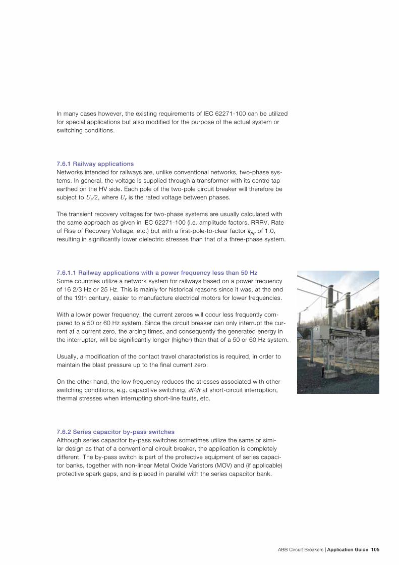
ABB Circuit Breakers | Application Guide 105
In many cases however, the existing requirements of IEC 62271-100 can be utilized for special applications but also modified for the purpose of the actual system or switching conditions.
7.6.1 Railway applicationsNetworks intended for railways are, unlike conventional networks, two-phase sys-tems. In general, the voltage is supplied through a transformer with its centre tap earthed on the HV side. Each pole of the two-pole circuit breaker will therefore be subject to Ur/2, where Ur is the rated voltage between phases.
The transient recovery voltages for two-phase systems are usually calculated with the same approach as given in IEC 62271-100 (i.e. amplitude factors, RRRV, Rate of Rise of Recovery Voltage, etc.) but with a first-pole-to-clear factor kpp of 1.0, resulting in significantly lower dielectric stresses than that of a three-phase system.
7.6.1.1 Railway applications with a power frequency less than 50 HzSome countries utilize a network system for railways based on a power frequency of 16 2/3 Hz or 25 Hz. This is mainly for historical reasons since it was, at the end of the 19th century, easier to manufacture electrical motors for lower frequencies.
With a lower power frequency, the current zeroes will occur less frequently com-pared to a 50 or 60 Hz system. Since the circuit breaker can only interrupt the cur-rent at a current zero, the arcing times, and consequently the generated energy in the interrupter, will be significantly longer (higher) than that of a 50 or 60 Hz system.
Usually, a modification of the contact travel characteristics is required, in order to maintain the blast pressure up to the final current zero.
On the other hand, the low frequency reduces the stresses associated with other switching conditions, e.g. capacitive switching, di/dt at short-circuit interruption, thermal stresses when interrupting short-line faults, etc.
7.6.2 Series capacitor by-pass switchesAlthough series capacitor by-pass switches sometimes utilize the same or simi-lar design as that of a conventional circuit breaker, the application is completely different. The by-pass switch is part of the protective equipment of series capaci-tor banks, together with non-linear Metal Oxide Varistors (MOV) and (if applicable) protective spark gaps, and is placed in parallel with the series capacitor bank.
106 Application Guide | ABB Circuit Breakers
The main purpose with the by-pass switch is to deliberately by-pass and insert the series capacitor (planned operation) and for protective by-passing of the series capacitor in case of faults.
Hence, under normal service conditions when the series capacitor is connected in se-ries with the overhead line, the by-pass switch is in open position and always prepared to by-pass the series capacitor bank in case of faults or any planned operations.
The main stresses related to switching of by-pass switches are the following:a. By-pass making of series capacitor
The by-pass switch must be able to by-pass the series capacitor bank when it is precharged to its protective level (limiting voltage of the overvoltage protector) and consequently withstand the associated inrush current from the capacitor bank superimposed on the line fault current.
b. Insertion of the series capacitor The by-pass switch must be able to transfer the load current from the by-pass circuit path to the series capacitor path and withstand the associated recovery voltage, with peak values of up to its protective level, without restriking. In addition, the by-pass switch must be able to carry the rated current and the rated short-circuit current in closed position, as well as to withstand the overvolt-ages specified across open gap and phase-to-earth. It should be noted, however, that the by-pass switch is not intended to interrupt short-circuit currents which may occur in the system. IEC 62271-109 is applicable for ac series capacitor by-pass switches.
7.6.3 HVDC filtersHVDC ac filters are intended to supply reactive power to the network and to reduce the amplitude of harmonics on the voltage of the ac network.
The filter circuit breakers may therefore be subjected to frequent operation since the need for reactive power compensation may change several times per day.
During these planned operations (normal conditions), the stress on the circuit breaker is similar to that of switching of a capacitor bank with earthed neutral, i.e. a moderate recovery voltage when de-energizing the filter bank. The inrush currents during energizing are usually fairly low since the filters contain inductances in order to tune the filters for the correct frequencies. Furthermore, it is common to utilize controlled switching for energizing of filter banks.
Significantly higher stresses may be obtained when a fault occurs on the ac line with a consequent tripping of the converter and disconnecting of the faulty line. In this case, overvoltages may appear which makes it necessary to disconnect the filters from the bus. The overvoltages on the bus will naturally result in significantly higher recovery voltages than those seen during normal switching conditions.
7. Application
ABB Circuit Breakers | Application Guide 107
In addition, the high amount of harmonics on the supply voltage may create higher RRRV (Rate of Rise of Recovery Voltage).
Typical values of the highest peak of the recovery voltage are in the range of 2.8 – 3.2 p.u.
System studies are usually performed as the basis for the technical requirements for filter bank circuit breakers. The results should be subject to a statistical evaluation in order to define the probability of the most severe switching cases.
7.6.4 SVC (Static Var Compensator)The SVC can dynamically provide reactive power compensation to the network by means of Thyristor Controlled Reactors (TCR) or Thyristor Switched Capacitors (TSC). The SVC is usually installed at a significantly lower voltage than the main bus, fed through an SVC transformer.
In some cases circuit breakers are installed in the TCR or TSC branches. These cir-cuit breakers are generally infrequently operated, but the low voltage will result in very high requirements for the rated current, usually in the range of 2,000 – 4,000 A, and very high short-circuit current carrying capability. In addition, the harmonics should be taken into account for the continuous current capability.
Some installations also require Mechanically Switched Capacitor banks (MSC) in parallel to the thyristor controlled branches. The combination of frequent operations and high load currents (including high frequent inrush currents) may require signifi-cantly higher capability than that normally required for these voltages.
7.7 Instrument transformers and relays in combination with live tank circuit breakersWhen comparing the properties of live tank and dead tank circuit breakers, the location of adjacent current transformers is sometimes a concern.
For a dead tank circuit breaker, ring-core current transformers are placed on the bush-ings. Normally there are current transformers on both sides of the circuit breaker, and the two sets of transformers are applied to give overlapping protection zones. With the two sets it is also possible to detect earth faults/short-circuits within the dead tank circuit breaker itself, in the same manner as for a power transformer (differential protection). The possibility of such internal faults cannot be ruled out.
For a live tank circuit breaker, a single set of current transformers is used, and placed on either side of the circuit breaker. In a live tank design, the risk of earth faults or internal short-circuits may be ruled out, and there is no need for a duplica-tion of the transformers.
108 Application Guide | ABB Circuit Breakers
A thorough comparison of the two alternatives shows that a dead tank circuit breaker with current transformers on both sides, and a live tank circuit breaker with current transformers on one side, have identical, or almost identical, function with regard to the relay protection.
7.8 Controlled switchingThere are several important circuit breaker applications where random closing or opening instants may lead to severe voltage and current switching transients. These transients occur in the main circuits, but may also induce transients in control and auxiliary circuits, as well as in adjacent low voltage systems. The switching transients are associated with a variety of dielectric and mechanical stresses on the high-voltage equipment, and may cause gradual or immediate damage to the system or the equipment. Induced transients may lead to a variety of disturbances, e.g. in substation control and protection systems, computers and processors, or telecommunications.
Controlled switching is a method for eliminating harmful transients via time-con-trolled switching operations. Closing or opening commands to the circuit breaker are delayed in such a way that making or contact separation will occur at the opti-mum time instant related to the phase angle. By means of Switchsync™ controllers, both energizing and de-energizing operations can be controlled with regard to the point-on-wave position, and no harmful transients will be generated.
The subject of controlled switching is dealt with in detail in ABB Controlled Switching, Buyer’s and Application Guide.
7. Application
ABB Circuit Breakers | Application Guide 109
8.1 StandardsThe major international standards for circuit breakers are IEC1 and ANSI2/IEEE3. In addition to these standards, there also exist several region-specific standards often based on IEC and ANSI requirements.
The USA-based standards were originally developed and intended for use in the USA. Over the last 15 years a gradual change has taken place in the IEEE, and now there is a genuine interest in harmonizing the IEC and IEEE standards.
1. International Electrotechnical Commission2. American National Standards Institute3. The Institute of Electrical and Electronics Engineers, Inc.
8.1.1 IECSome years ago, the former standard IEC 60056 was replaced by the now valid IEC 62271-100 “High-voltage alternating current circuit-breakers.” One main objective when forming the -100 circuit breaker standard was to raise the require-ments related to switching of capacitive loads, since service experiences had shown they were insufficient. Other changes were implemented at the same time. The capacitive switching classes C1 and C2 were introduced together with the mechanical endurance classes M1 and M2.
IEC has published several standard parts with the number IEC 62271 as a base. The list below shows some of the standard parts most relevant for the circuit break-ers, old names are also listed:
IEC 62271- Title Old name
Part
-1 Common specifications IEC 60694
-100 High-voltage alternating current circuit breakers IEC 60056
-101 Synthetic testing IEC 60427
-108 High-voltage ac disconnecting circuit breakers for rated
voltages of 72.5 kV and above
-
-110 Inductive load switching IEC 61233
-300 Guide for seismic qualification IEC 61166
-302 Guide for short-circuit and switching test procedures for
metal-enclosed and dead tank circuit breakers
IEC 61633
-303 Use and handling of sulphur hexafluoride (SF6) in high-voltage
switchgear and Controlgear
IEC 61634
Table 8.1 Examples of IEC Standards for high voltage circuit breakers
IEC refers to CIGRE Technical Brochures 304 and 305 to provide background information concerning facts and figures, and to give a basis for specifications. In a similar manner, the American standards refer to IEEE application guides.
8. Standards and tests
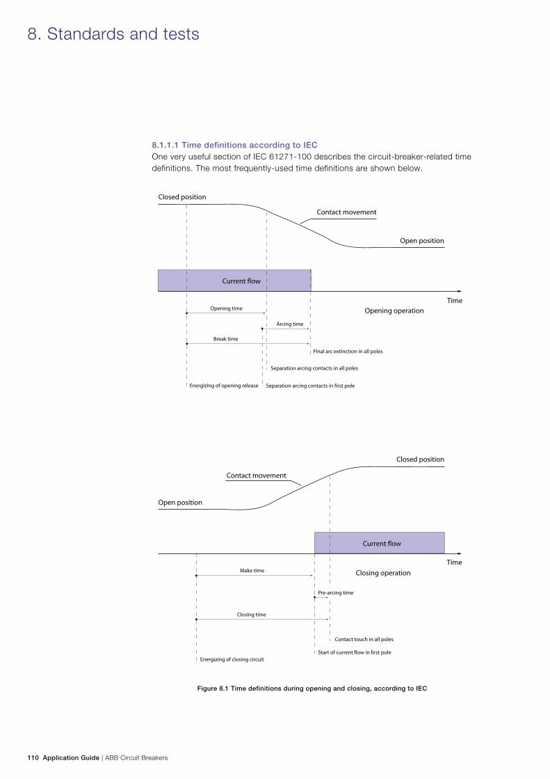
110 Application Guide | ABB Circuit Breakers
8.1.1.1 Time definitions according to IECOne very useful section of IEC 61271-100 describes the circuit-breaker-related time definitions. The most frequently-used time definitions are shown below.
Figure 8.1 Time definitions during opening and closing, according to IEC
8. Standards and tests
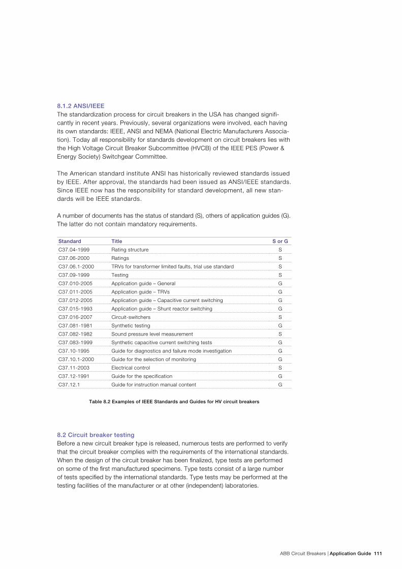
ABB Circuit Breakers | Application Guide 111
8.1.2 ANSI/IEEEThe standardization process for circuit breakers in the USA has changed signifi-cantly in recent years. Previously, several organizations were involved, each having its own standards: IEEE, ANSI and NEMA (National Electric Manufacturers Associa-tion). Today all responsibility for standards development on circuit breakers lies with the High Voltage Circuit Breaker Subcommittee (HVCB) of the IEEE PES (Power & Energy Society) Switchgear Committee.
The American standard institute ANSI has historically reviewed standards issued by IEEE. After approval, the standards had been issued as ANSI/IEEE standards. Since IEEE now has the responsibility for standard development, all new stan-dards will be IEEE standards.
A number of documents has the status of standard (S), others of application guides (G). The latter do not contain mandatory requirements.
Standard Title S or G
C37.04-1999 Rating structure S
C37.06-2000 Ratings S
C37.06.1-2000 TRVs for transformer limited faults, trial use standard S
C37.09-1999 Testing S
C37.010-2005 Application guide – General G
C37.011-2005 Application guide – TRVs G
C37.012-2005 Application guide – Capacitive current switching G
C37.015-1993 Application guide – Shunt reactor switching G
C37.016-2007 Circuit-switchers S
C37.081-1981 Synthetic testing G
C37.082-1982 Sound pressure level measurement S
C37.083-1999 Synthetic capacitive current switching tests G
C37.10-1995 Guide for diagnostics and failure mode investigation G
C37.10.1-2000 Guide for the selection of monitoring G
C37.11-2003 Electrical control S
C37.12-1991 Guide for the specification G
C37.12.1 Guide for instruction manual content G
Table 8.2 Examples of IEEE Standards and Guides for HV circuit breakers
8.2 Circuit breaker testingBefore a new circuit breaker type is released, numerous tests are performed to verify that the circuit breaker complies with the requirements of the international standards. When the design of the circuit breaker has been finalized, type tests are performed on some of the first manufactured specimens. Type tests consist of a large number of tests specified by the international standards. Type tests may be performed at the testing facilities of the manufacturer or at other (independent) laboratories.
112 Application Guide | ABB Circuit Breakers
8. Standards and tests
Type testing is a “must” for circuit breakers. It is a verification that the circuit break-er will be able to handle the stresses in the network in which it will be installed. At the same time it is an official verification of the ratings that the manufacturer has assigned to the circuit breaker.
Type tests consist of the following tests (IEC 62271-100): − Dielectric tests − Radio Interference Voltage (RIV) tests − Temperature rise tests − Measurement of the resistance of the main circuit − Short-time current and peak withstand current tests − Mechanical and environmental tests − Making and breaking tests
Of the type tests, the making and breaking tests are the most comprehensive, since they involve tests on the circuit breaker at different current levels and different TRV’s to cover the different fault cases as described in Section 3. Because of the electri-cal power required and the special equipment involved in these tests, making and breaking tests are the most expensive tests performed on a circuit breaker.
Most of the type tests lead to significant wear and the circuit breakers cannot be delivered to customers after the tests. Several circuit breakers will be needed to complete one set of type tests for a circuit breaker type.
Routine tests are performed on each circuit breaker manufactured, with the pur-pose of revealing faults in material or assembly.
8.3 Type testsIn this section a brief description is given of the different type tests that are required by IEC 62271-100. Major differences between IEC and IEEE standard C37.09 are highlighted.
8.3.1 Dielectric testsIn a dielectric test, the circuit breaker is exposed to the different types of overvoltages as described in Section 6 (lightning impulse, switching impulse and power frequency).
In addition to the tests on the circuit breaker pole, the control wiring shall be sub-jected to a 2 kV, 1 min. power frequency withstand test in accordance with IEC. The test voltage in accordance with IEEE is 1,500 V during one minute, or alternatively 1,800 V during one second.
ABB Circuit Breakers | Application Guide 113
8.3.2 Radio Interference Voltage (RIV) testsRIV tests are performed in order to establish the degree to which the circuit breaker interferes with radio communication when energized. For further details see Section 6.4.3.1.
8.3.3 Temperature rise testsIn a temperature rise test on the main circuit, the rated normal current is conduct-ed through the circuit breaker and the temperature rise (difference between the measured and the ambient temperature) of the crucial parts (contacts, connec-tions and terminals) is measured by means of suitable temperature sensors. See also Section 5.2.
The test duration is dependent on when the temperature of the circuit breaker has stabilized and reached a steady state condition. This requirement is, according to IEC, considered to be fulfilled when the temperature increase is less than 1 K per hour. IEEE states that the temperature shall not change by more than 1 K as indi-cated by three successive readings at 30 min. intervals.
Gas-filled circuit breakers should be filled to a pressure equal to the specified mini-mum pressure (lock-out pressure) in accordance with IEC 62271-1. IEEE states that the test shall be performed under usual service conditions (i.e. rated pressure).
The limits of the temperature rise of the parts of the circuit breaker are given in IEC 62271-1, Table 3 and in IEEE C37.04 Table 1.
In addition to the temperature rise test on the main circuit, IEC requires a temperature rise test to be performed on the auxiliary equipment (coils, motors etc.). The circuit breaker is operated 10 times in rapid succession (minimal time between operations), after which the temperature rise is measured through resistance measurement.
8.3.4 Measurement of the resistance of the main circuitResistance measurement of the main circuit is performed before and after the tem-perature rise test. A dc-current of at least 50 A is fed through the circuit breaker and the voltage drop between the terminals is measured. The difference between the resistance measured before and after the temperature rise test is limited to ± 20%.
8.3.5 Short-time withstand current and peak withstand current testsThis test is performed with the circuit breaker in the closed position. The full short-circuit current is conducted through the circuit breaker for a specified duration. The circuit breaker is considered to have passed the test successfully if there is no me-chanical damage and if the circuit breaker opens at the first attempt after the test with no significant change in opening time (i.e. no contact welding has taken place).
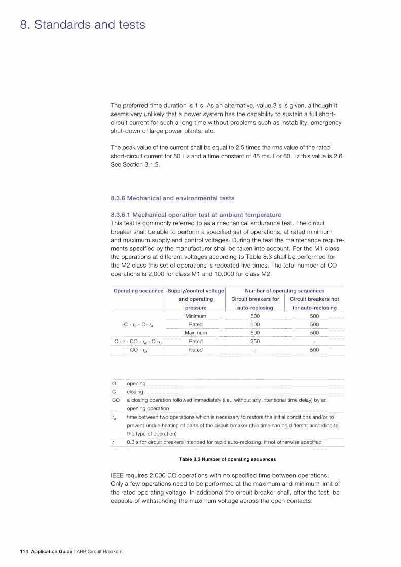
114 Application Guide | ABB Circuit Breakers
The preferred time duration is 1 s. As an alternative, value 3 s is given, although it seems very unlikely that a power system has the capability to sustain a full short-circuit current for such a long time without problems such as instability, emergency shut-down of large power plants, etc.
The peak value of the current shall be equal to 2.5 times the rms value of the rated short-circuit current for 50 Hz and a time constant of 45 ms. For 60 Hz this value is 2.6. See Section 3.1.2.
8.3.6 Mechanical and environmental tests 8.3.6.1 Mechanical operation test at ambient temperatureThis test is commonly referred to as a mechanical endurance test. The circuit breaker shall be able to perform a specified set of operations, at rated minimum and maximum supply and control voltages. During the test the maintenance require-ments specified by the manufacturer shall be taken into account. For the M1 class the operations at different voltages according to Table 8.3 shall be performed for the M2 class this set of operations is repeated five times. The total number of CO operations is 2,000 for class M1 and 10,000 for class M2.
Operating sequence Supply/control voltage
and operating
pressure
Number of operating sequences
Circuit breakers for
auto-reclosing
Circuit breakers not
for auto-reclosing
C - ta - O- ta
Minimum 500 500
Rated 500 500
Maximum 500 500
C - t - CO - ta - C -ta Rated 250 -
CO - ta Rated - 500
O opening
C closing
CO a closing operation followed immediately (i.e., without any intentional time delay) by an
opening operation
ta time between two operations which is necessary to restore the initial conditions and/or to
prevent undue heating of parts of the circuit breaker (this time can be different according to
the type of operation)
t 0.3 s for circuit breakers intended for rapid auto-reclosing, if not otherwise specified
Table 8.3 Number of operating sequences
IEEE requires 2,000 CO operations with no specified time between operations. Only a few operations need to be performed at the maximum and minimum limit of the rated operating voltage. In additional the circuit breaker shall, after the test, be capable of withstanding the maximum voltage across the open contacts.
8. Standards and tests
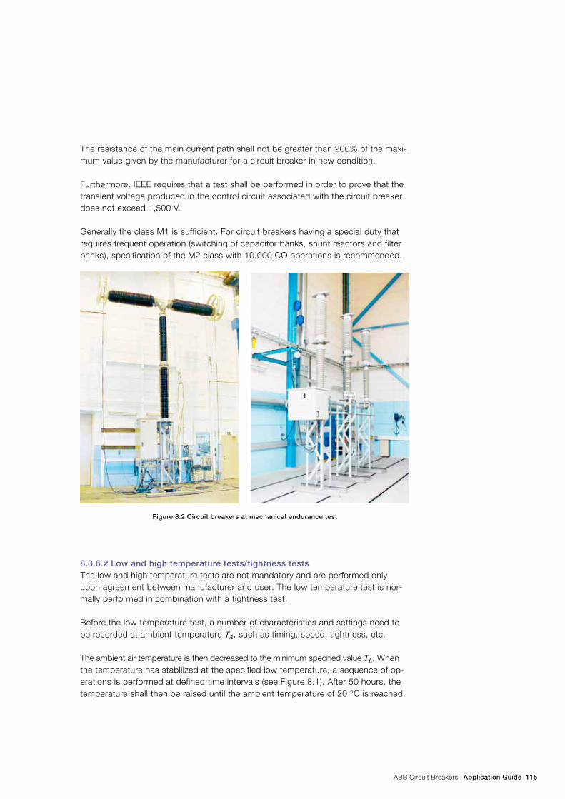
ABB Circuit Breakers | Application Guide 115
The resistance of the main current path shall not be greater than 200% of the maxi-mum value given by the manufacturer for a circuit breaker in new condition.
Furthermore, IEEE requires that a test shall be performed in order to prove that the transient voltage produced in the control circuit associated with the circuit breaker does not exceed 1,500 V.
Generally the class M1 is sufficient. For circuit breakers having a special duty that requires frequent operation (switching of capacitor banks, shunt reactors and filter banks), specification of the M2 class with 10,000 CO operations is recommended.
Figure 8.2 Circuit breakers at mechanical endurance test
8.3.6.2 Low and high temperature tests/tightness testsThe low and high temperature tests are not mandatory and are performed only upon agreement between manufacturer and user. The low temperature test is nor-mally performed in combination with a tightness test.
Before the low temperature test, a number of characteristics and settings need to be recorded at ambient temperature TA, such as timing, speed, tightness, etc.
The ambient air temperature is then decreased to the minimum specified value TL. When the temperature has stabilized at the specified low temperature, a sequence of op-erations is performed at defined time intervals (see Figure 8.1). After 50 hours, the temperature shall then be raised until the ambient temperature of 20 °C is reached.
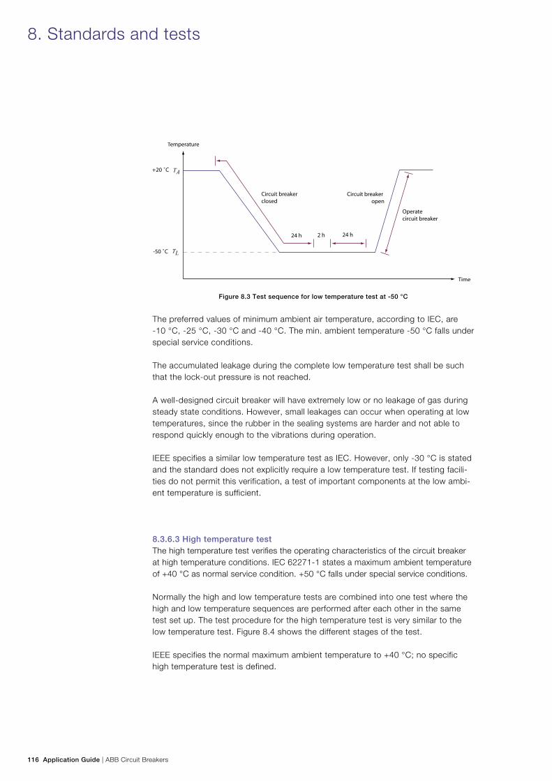
116 Application Guide | ABB Circuit Breakers
8. Standards and tests
Figure 8.3 Test sequence for low temperature test at -50 °C
The preferred values of minimum ambient air temperature, according to IEC, are -10 °C, -25 °C, -30 °C and -40 °C. The min. ambient temperature -50 °C falls under special service conditions.
The accumulated leakage during the complete low temperature test shall be such that the lock-out pressure is not reached.
A well-designed circuit breaker will have extremely low or no leakage of gas during steady state conditions. However, small leakages can occur when operating at low temperatures, since the rubber in the sealing systems are harder and not able to respond quickly enough to the vibrations during operation.
IEEE specifies a similar low temperature test as IEC. However, only -30 °C is stated and the standard does not explicitly require a low temperature test. If testing facili-ties do not permit this verification, a test of important components at the low ambi-ent temperature is sufficient.
8.3.6.3 High temperature testThe high temperature test verifies the operating characteristics of the circuit breaker at high temperature conditions. IEC 62271-1 states a maximum ambient temperature of +40 °C as normal service condition. +50 °C falls under special service conditions.
Normally the high and low temperature tests are combined into one test where the high and low temperature sequences are performed after each other in the same test set up. The test procedure for the high temperature test is very similar to the low temperature test. Figure 8.4 shows the different stages of the test.
IEEE specifies the normal maximum ambient temperature to +40 °C; no specific high temperature test is defined.
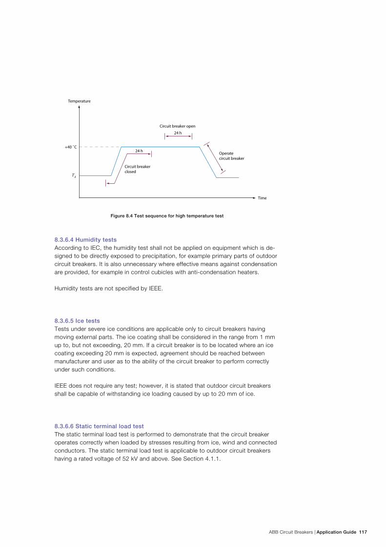
ABB Circuit Breakers | Application Guide 117
Figure 8.4 Test sequence for high temperature test
8.3.6.4 Humidity testsAccording to IEC, the humidity test shall not be applied on equipment which is de-signed to be directly exposed to precipitation, for example primary parts of outdoor circuit breakers. It is also unnecessary where effective means against condensation are provided, for example in control cubicles with anti-condensation heaters.
Humidity tests are not specified by IEEE.
8.3.6.5 Ice testsTests under severe ice conditions are applicable only to circuit breakers having moving external parts. The ice coating shall be considered in the range from 1 mm up to, but not exceeding, 20 mm. If a circuit breaker is to be located where an ice coating exceeding 20 mm is expected, agreement should be reached between manufacturer and user as to the ability of the circuit breaker to perform correctly under such conditions.
IEEE does not require any test; however, it is stated that outdoor circuit breakers shall be capable of withstanding ice loading caused by up to 20 mm of ice.
8.3.6.6 Static terminal load testThe static terminal load test is performed to demonstrate that the circuit breaker operates correctly when loaded by stresses resulting from ice, wind and connected conductors. The static terminal load test is applicable to outdoor circuit breakers having a rated voltage of 52 kV and above. See Section 4.1.1.
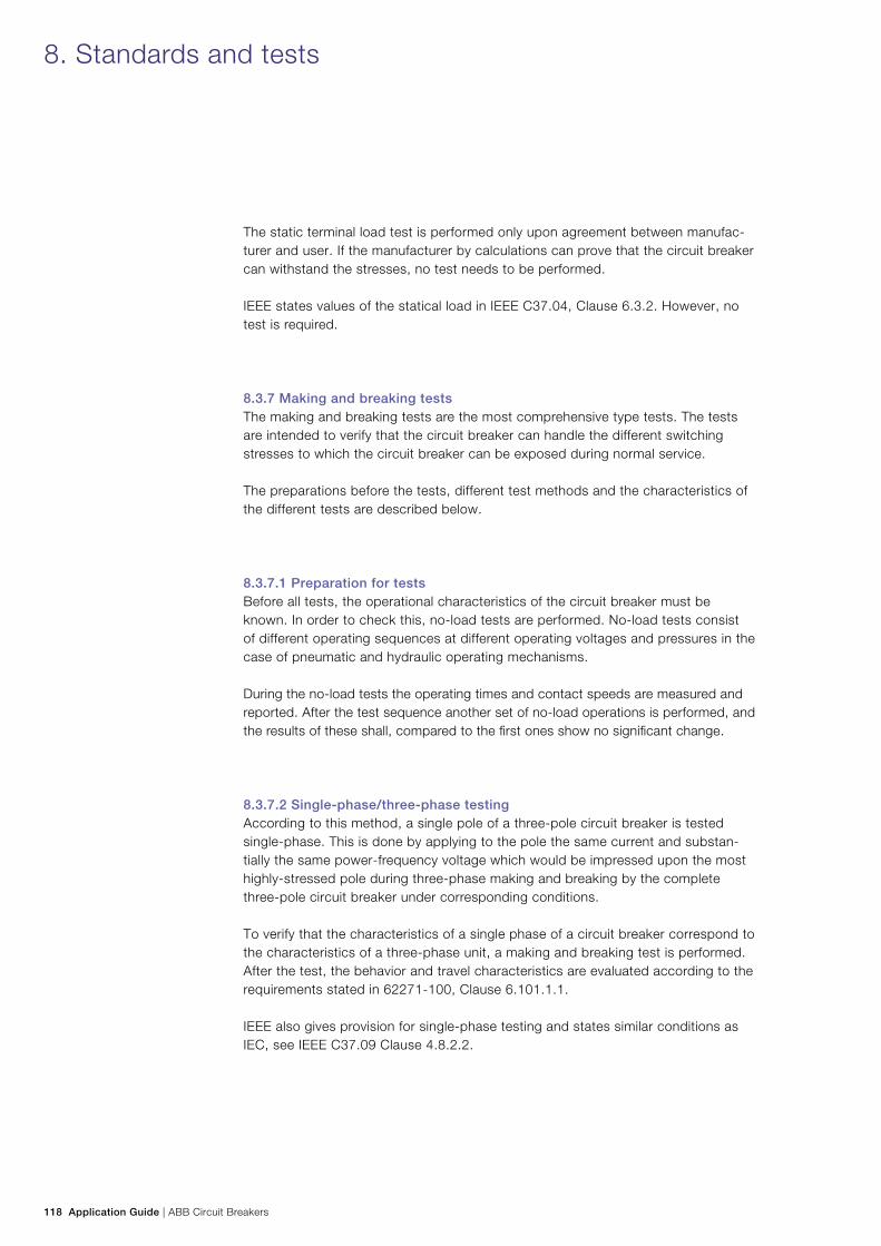
118 Application Guide | ABB Circuit Breakers
The static terminal load test is performed only upon agreement between manufac-turer and user. If the manufacturer by calculations can prove that the circuit breaker can withstand the stresses, no test needs to be performed.
IEEE states values of the statical load in IEEE C37.04, Clause 6.3.2. However, no test is required.
8.3.7 Making and breaking testsThe making and breaking tests are the most comprehensive type tests. The tests are intended to verify that the circuit breaker can handle the different switching stresses to which the circuit breaker can be exposed during normal service.
The preparations before the tests, different test methods and the characteristics of the different tests are described below.
8.3.7.1 Preparation for testsBefore all tests, the operational characteristics of the circuit breaker must be known. In order to check this, no-load tests are performed. No-load tests consist of different operating sequences at different operating voltages and pressures in the case of pneumatic and hydraulic operating mechanisms.
During the no-load tests the operating times and contact speeds are measured and reported. After the test sequence another set of no-load operations is performed, and the results of these shall, compared to the first ones show no significant change.
8.3.7.2 Single-phase/three-phase testingAccording to this method, a single pole of a three-pole circuit breaker is tested single-phase. This is done by applying to the pole the same current and substan-tially the same power-frequency voltage which would be impressed upon the most highly-stressed pole during three-phase making and breaking by the complete three-pole circuit breaker under corresponding conditions.
To verify that the characteristics of a single phase of a circuit breaker correspond to the characteristics of a three-phase unit, a making and breaking test is performed. After the test, the behavior and travel characteristics are evaluated according to the requirements stated in 62271-100, Clause 6.101.1.1.
IEEE also gives provision for single-phase testing and states similar conditions as IEC, see IEEE C37.09 Clause 4.8.2.2.
8. Standards and tests
ABB Circuit Breakers | Application Guide 119
8.3.7.3 Unit test/full pole test Owing to limitations in the high power laboratories, full pole testing is not always possible, especially with the recent development of breaking units with a high volt-age rating. In such cases unit tests, or half pole tests, may be performed. Unit tests are allowed if the requirements according to IEC 62271-100, 6.102.4.2 are fulfilled. For example, the following requirements must be fulfilled:
− the units of the circuit breaker shall be identical in shape, dimension and operat-ing conditions
− the operating energy shall be adjusted in such a way that the contact movement does not differ from that of the full pole
− the voltage distribution between the breaking units must be considered. The test voltage shall be the voltage of the most highly-stressed breaking unit of the complete pole of the circuit breaker.
IEEE C37.09, Section 4.8.2.3.1 specifies the corresponding requirements for unit testing.
8.3.7.4 Direct testsDirect tests are characterized by one source giving the correct current before inter-ruption and the correct voltage stresses after the interruption (see Figure 8.5).
The nature of direct testing is rather simple. In the case of direct testing, the circuit breaker chooses the best current zero in which to interrupt. The setting of the initia-tion of the short-circuit as well as the contact separation is well-defined.
Figure 8.5 Single phase test circuit for direct test
G Short-circuit generator
MB Master circuit breaker
MS Making switch
L Reactor for limitation of short-circuit current
R, C Oscillatory circuit for TRV
TB Test circuit breaker
T Transformer
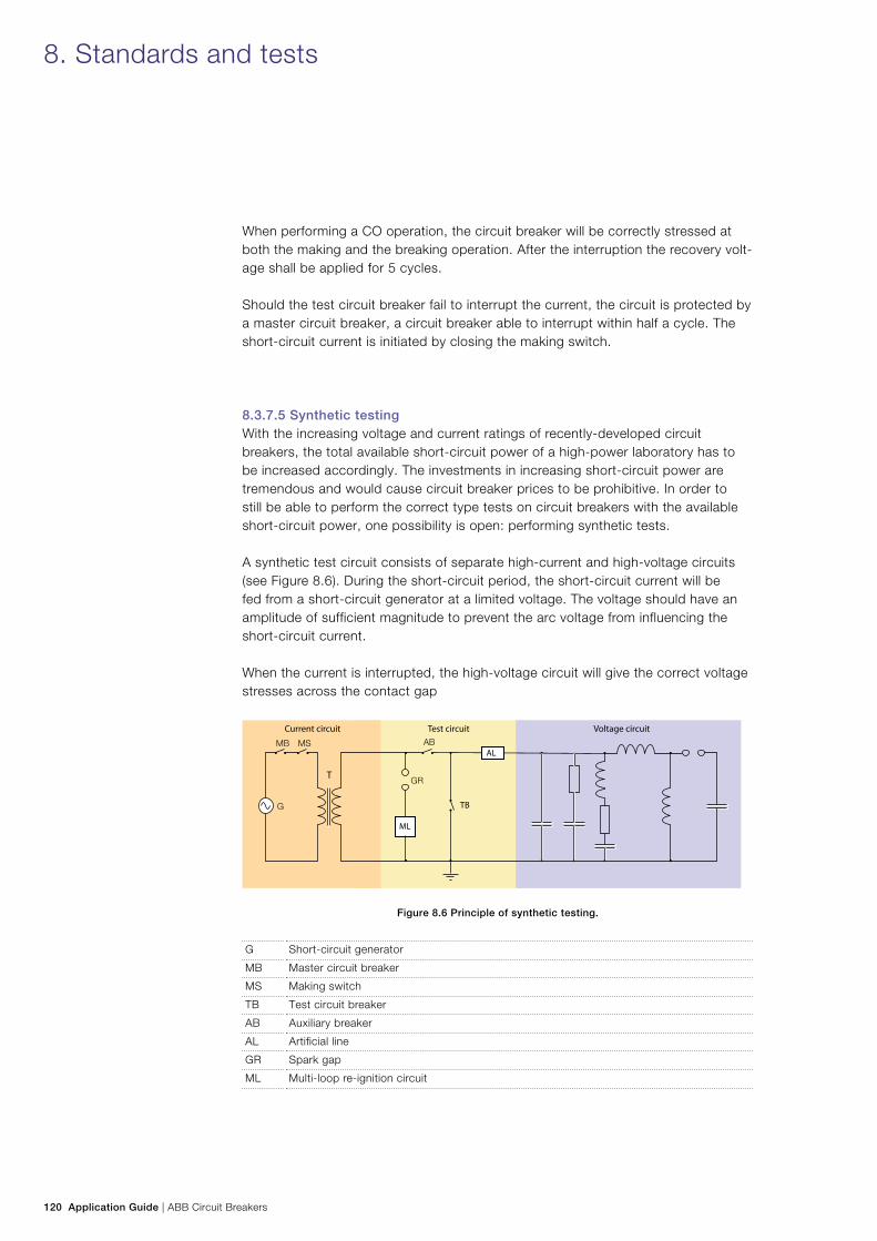
120 Application Guide | ABB Circuit Breakers
When performing a CO operation, the circuit breaker will be correctly stressed at both the making and the breaking operation. After the interruption the recovery volt-age shall be applied for 5 cycles.
Should the test circuit breaker fail to interrupt the current, the circuit is protected by a master circuit breaker, a circuit breaker able to interrupt within half a cycle. The short-circuit current is initiated by closing the making switch.
8.3.7.5 Synthetic testingWith the increasing voltage and current ratings of recently-developed circuit breakers, the total available short-circuit power of a high-power laboratory has to be increased accordingly. The investments in increasing short-circuit power are tremendous and would cause circuit breaker prices to be prohibitive. In order to still be able to perform the correct type tests on circuit breakers with the available short-circuit power, one possibility is open: performing synthetic tests.
A synthetic test circuit consists of separate high-current and high-voltage circuits (see Figure 8.6). During the short-circuit period, the short-circuit current will be fed from a short-circuit generator at a limited voltage. The voltage should have an amplitude of sufficient magnitude to prevent the arc voltage from influencing the short-circuit current.
When the current is interrupted, the high-voltage circuit will give the correct voltage stresses across the contact gap
Figure 8.6 Principle of synthetic testing.
G Short-circuit generator
MB Master circuit breaker
MS Making switch
TB Test circuit breaker
AB Auxiliary breaker
AL Artificial line
GR Spark gap
ML Multi-loop re-ignition circuit
8. Standards and tests
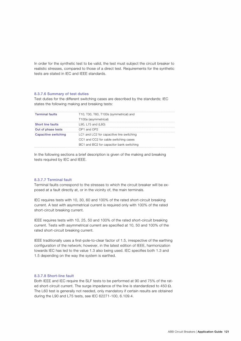
ABB Circuit Breakers | Application Guide 121
In order for the synthetic test to be valid, the test must subject the circuit breaker to realistic stresses, compared to those of a direct test. Requirements for the synthetic tests are stated in IEC and IEEE standards.
8.3.7.6 Summary of test dutiesTest duties for the different switching cases are described by the standards; IEC states the following making and breaking tests:
Terminal faults T10, T30, T60, T100s (symmetrical) and
T100a (asymmetrical)
Short line faults L90, L75 and (L60)
Out of phase tests OP1 and OP2
Capacitive switching LC1 and LC2 for capacitive line switching
CC1 and CC2 for cable switching cases
BC1 and BC2 for capacitor bank switching
In the following sections a brief description is given of the making and breaking tests required by IEC and IEEE.
8.3.7.7 Terminal faultTerminal faults correspond to the stresses to which the circuit breaker will be ex-posed at a fault directly at, or in the vicinity of, the main terminals.
IEC requires tests with 10, 30, 60 and 100% of the rated short-circuit breaking current. A test with asymmetrical current is required only with 100% of the rated short-circuit breaking current.
IEEE requires tests with 10, 25, 50 and 100% of the rated short-circuit breaking current. Tests with asymmetrical current are specified at 10, 50 and 100% of the rated short-circuit breaking current.
IEEE traditionally uses a first-pole-to-clear factor of 1.5, irrespective of the earthing configuration of the network; however, in the latest edition of IEEE, harmonization towards IEC has led to the value 1.3 also being used. IEC specifies both 1.3 and 1.5 depending on the way the system is earthed.
8.3.7.8 Short-line faultBoth IEEE and IEC require the SLF tests to be performed at 90 and 75% of the rat-ed short-circuit current. The surge impedance of the line is standardized to 450 Ω. The L60 test is generally not needed, only mandatory if certain results are obtained during the L90 and L75 tests, see IEC 62271-100, 6.109.4.
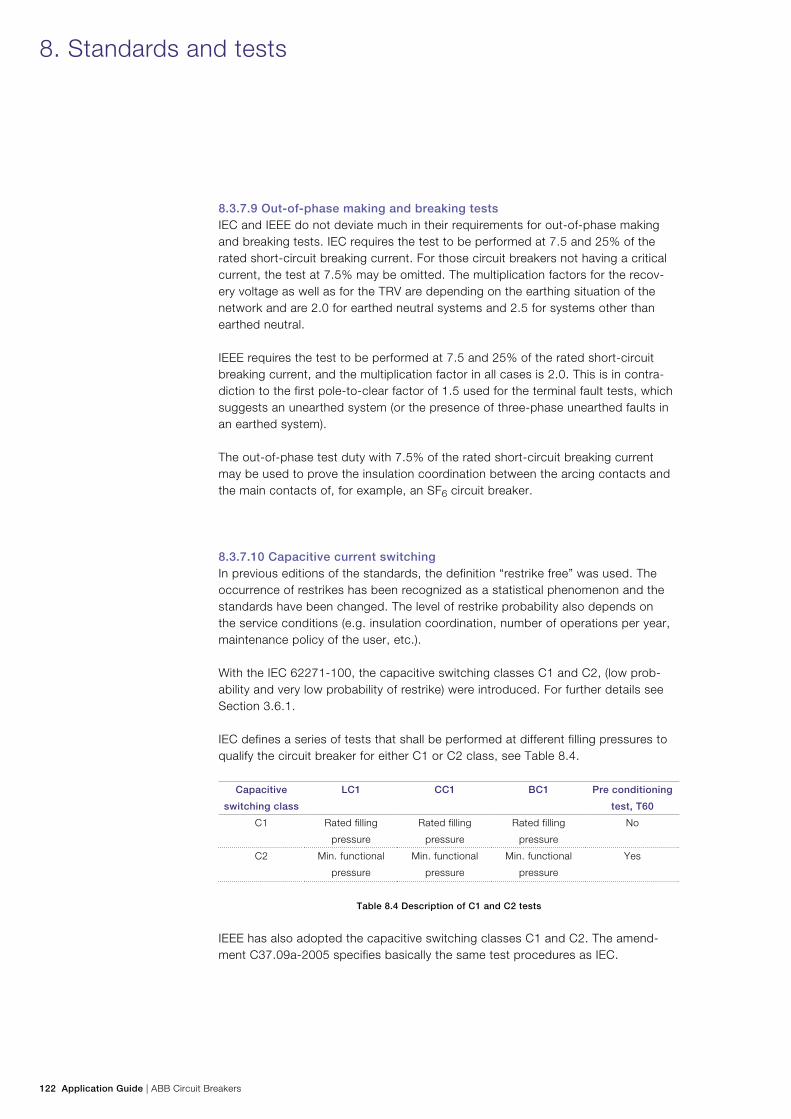
122 Application Guide | ABB Circuit Breakers
8.3.7.9 Out-of-phase making and breaking testsIEC and IEEE do not deviate much in their requirements for out-of-phase making and breaking tests. IEC requires the test to be performed at 7.5 and 25% of the rated short-circuit breaking current. For those circuit breakers not having a critical current, the test at 7.5% may be omitted. The multiplication factors for the recov-ery voltage as well as for the TRV are depending on the earthing situation of the network and are 2.0 for earthed neutral systems and 2.5 for systems other than earthed neutral.
IEEE requires the test to be performed at 7.5 and 25% of the rated short-circuit breaking current, and the multiplication factor in all cases is 2.0. This is in contra-diction to the first pole-to-clear factor of 1.5 used for the terminal fault tests, which suggests an unearthed system (or the presence of three-phase unearthed faults in an earthed system).
The out-of-phase test duty with 7.5% of the rated short-circuit breaking current may be used to prove the insulation coordination between the arcing contacts and the main contacts of, for example, an SF6 circuit breaker.
8.3.7.10 Capacitive current switchingIn previous editions of the standards, the definition “restrike free” was used. The occurrence of restrikes has been recognized as a statistical phenomenon and the standards have been changed. The level of restrike probability also depends on the service conditions (e.g. insulation coordination, number of operations per year, maintenance policy of the user, etc.).
With the IEC 62271-100, the capacitive switching classes C1 and C2, (low prob-ability and very low probability of restrike) were introduced. For further details see Section 3.6.1.
IEC defines a series of tests that shall be performed at different filling pressures to qualify the circuit breaker for either C1 or C2 class, see Table 8.4.
Capacitive
switching class
LC1 CC1 BC1 Pre conditioning
test, T60
C1 Rated filling
pressure
Rated filling
pressure
Rated filling
pressure
No
C2 Min. functional
pressure
Min. functional
pressure
Min. functional
pressure
Yes
Table 8.4 Description of C1 and C2 tests
IEEE has also adopted the capacitive switching classes C1 and C2. The amend-ment C37.09a-2005 specifies basically the same test procedures as IEC.
8. Standards and tests
ABB Circuit Breakers | Application Guide 123
8.3.7.11 Shunt reactor current switching testsThe test procedure and theory about the interruption of small inductive currents is given in more detail in IEC 62271-110. The aim of the laboratory tests is to deter-mine the chopping number of the circuit breaker as well as the reignition behavior. The chopping number can be used to determine the overvoltages that will occur in an actual situation.
For shunt reactor applications with controlled switching, the reignition behavior of the circuit breaker will give information on how to properly set up the Switchsync™ controller.
IEEE Std C37.015-1993, “IEEE Application Guide for Shunt Reactor Current Switching,” gives the IEEE requirements for shunt reactor switching.
8.4 Routine testsRoutine or production tests are for the purpose of revealing faults in material or as-sembly of the daily production of circuit breakers. Routine tests shall be performed on each apparatus manufactured. Routine tests consist, among others, of the fol-lowing tests:
− Power frequency voltage withstand dry test on the main circuit − Voltage withstand tests on the control and auxiliary circuits. IEC requires the test
to be performed at 2,000 V, 1 min., IEEE requires the test to be performed at 1,500 V, 1 min
− Measurement of the resistance of the main circuit. The resistance of the main circuit is limited by IEC to 1.2 times the value obtained at the type test. IEEE states that the limit of the resistance of the main circuit shall be specified by the manufacturer.
− Mechanical operating times. The circuit breaker is operated a number of times at the limits of the control voltage, and during these tests the timing, speed etc. are checked against the values given by the manufacturer.
Furthermore, a number of other things are checked: compliance with the order specification, tightness, resistance of heaters and coils, etc. After verification the routine test report is provided to the customer as part of the order documentation.
8.5 Test reportsThis section contains information regarding type and routine test reports. A brief description is given about the different independent test organizations.
124 Application Guide | ABB Circuit Breakers
8.5.1 Type test reportsThe type test report shall describe the conditions during the test, the performance of the test and the result of the test. A summary of the tests by the manufacturer-assigned ratings and a specification of the tested object shall also be included.
A type test report shall contain the following minimum information: − A general section containing the date of the test(s), report numbers, oscillogram
numbers, etc. − An identification of the tested apparatus (type, type designation, manufacture,
dimension print, serial number, drawings, etc.). − Ratings assigned by the manufacturer. − Test conditions for each test. − Description of test circuits, applied voltages, breaking currents, operational times
of the circuit breaker, behavior and condition after the test.
8.5.2 Type test reports of independent laboratoriesSometimes a manufacturer may decide to have the circuit breaker performance verified by an independent test laboratory. This will give an official confirmation of the guaranteed performance of the circuit breaker. The tests performed at such laboratories are mainly short-circuit making and breaking tests.
8.5.3 STL organizationType test reports from independent laboratories have different formats, depend-ing on which laboratory issues them. Even the interpretation of the standards may differ from one laboratory to another. For this reason a number of laboratories have formed an organization with the objective of harmonizing test report formats, obtaining a uniform interpretation of IEC standards and harmonizing the measuring methods.
8. Standards and tests
ABB Circuit Breakers | Application Guide 125
This organization is named STL, which stands for Short-Circuit Testing Liaison. The full members of this organization are:
ASTA BEAB Certification Services UK
CESI Centro Elletrotecnico Sperimentale Italiano S.p.A. Italy
CPRI Central Power Research Institute India
ESEF Ensemble des Stations d’Essais à Grande Puissance Française France
JSTC Japanese Short-Circuit Testing Committee Japan
KEMA Netherlands
PEHLA Gesellschaft für Elektrische Hochleistungsprüfungen Germany and
Switzerland
SATS Scandinavian Association for Testing of Electric Power Equipment Sweden and
Norway
STLNA Short-Circuit Testing Liaison of the Nations of the Americas Canada, Mexico
and USA
8.5.4 SATS organizationSATS Certification is an association of Scandinavian manufacturers, independent test laboratories and end user organizations. The objective of SATS Certification is to issue Type Test Certificates and Certificates of Type Conformity for electric power equipment based on tests carried out in laboratories accredited to ISO/IEC 17025.
SATS Certification is a signatory member to the STL Agreement and is thereby authorised to issue STLA Certificates. The following laboratories are members of SATS:
ABB High Power Laboratory Ludvika, Sweden
NEFI Skien, Norway
NEXANS Halden, Norway
SINTEF Energy Research Trondheim, Norway
STRI AB Ludvika, Sweden
126 Application Guide | ABB Circuit Breakers
9.1 Failure statisticsInformation about failures and failure statistics is important for both system opera-tors and asset managers. Two types of statistics are used:
− System interruptions, i.e. loss of electrical power delivered to customers − Equipment failures.
An equipment failure may or may not lead to a system interruption.
International (equipment) failure statistics for circuit breakers are collected and published by Cigré. Two types of failures are considered: major failures and minor failures. A major failure will result in an immediate change in the system operating conditions, e.g. the backup protective equipment will be required to remove the fault, or will result in mandatory removal from service within 30 minutes for un-scheduled maintenance. A minor failure is a failure other than a major failure.
Examples of major failure categories are “does not open on command,” “opens without command,” “fails to carry current,” etc. Typical minor failures are small leak-ages of SF6 or hydraulic oil.
The overall average major failure rate for SF6 single pressure circuit breakers and rated voltages 63 – 800 kV published by Cigré is 0.67 failures/100 circuit breaker years (Final report of the second international enquiry on high voltage circuit breaker failures and defects in service, Cigré Technical Brochure No 83, 1994). A substan-tial share of the failures was caused by the operating mechanisms. Hydraulic and spring mechanisms had almost the same major failure rates, while the minor failure rate was much higher for the hydraulic mechanisms, due to oil leaks. The statistics do not give information about the performance of circuit breakers from individual manufacturers.
In general we recommend use of the Cigré failure statistics. They are based on a large population of circuit breakers from many countries around the world. The failures have been reported by the users (utilities, etc.) giving confidence that all failures are included.
9.2 Electrical and mechanical lifeAssuming that the recommended inspection intervals have been adhered to and that the appropriate measures have been implemented, ABB circuit breakers will have a service life exceeding 30 years and 2,000 (Class M1) or 10,000 (Class M2) mechanical operations.
9. Reliability, maintenance and life cycle costs
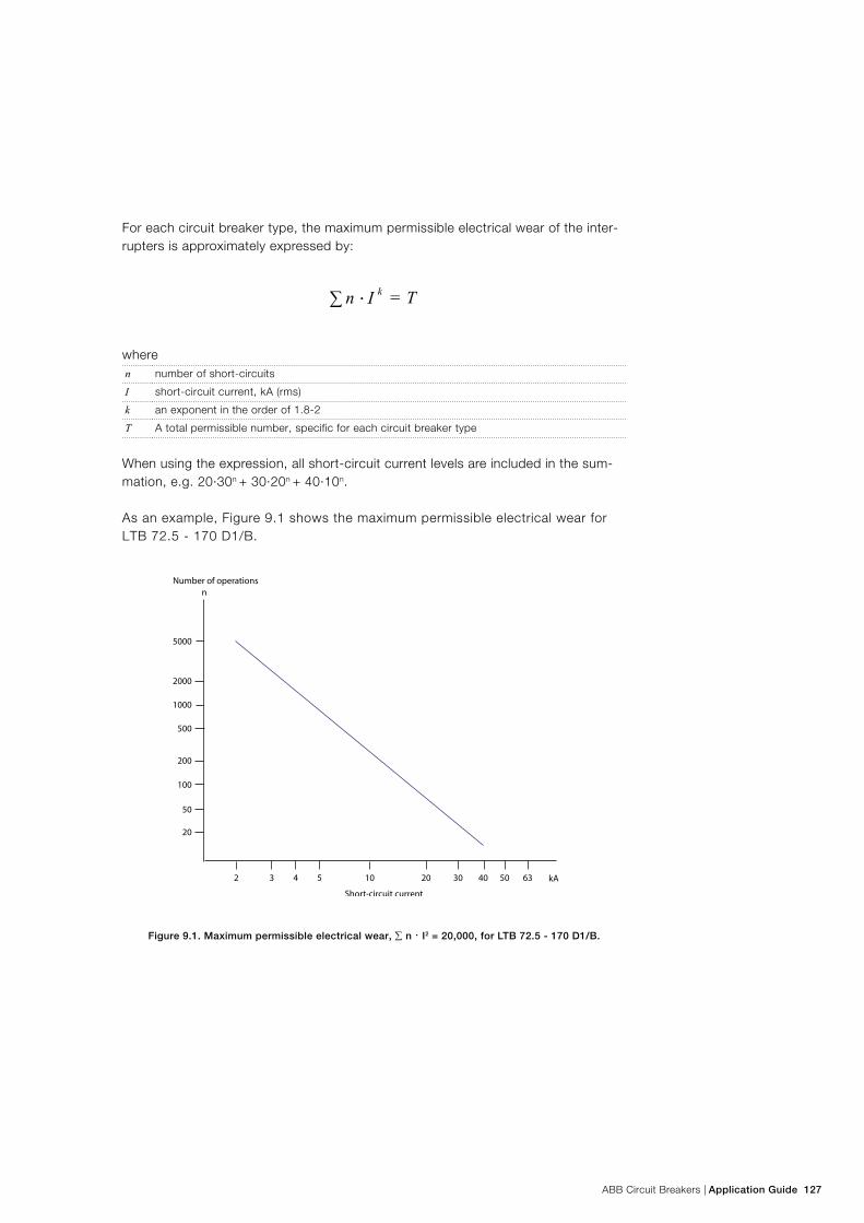
ABB Circuit Breakers | Application Guide 127
For each circuit breaker type, the maximum permissible electrical wear of the inter-rupters is approximately expressed by:
wheren number of short-circuits
I short-circuit current, kA (rms)
k an exponent in the order of 1.8-2
T A total permissible number, specific for each circuit breaker type
When using the expression, all short-circuit current levels are included in the sum-mation, e.g. 20·30n + 30·20n + 40·10n.
As an example, Figure 9.1 shows the maximum permissible electrical wear for LTB 72.5 - 170 D1/B.
Figure 9.1. Maximum permissible electrical wear, ∑ n · I2 = 20,000, for LTB 72.5 - 170 D1/B.
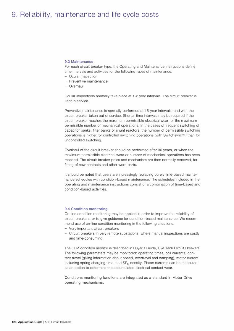
128 Application Guide | ABB Circuit Breakers
9.3 MaintenanceFor each circuit breaker type, the Operating and Maintenance Instructions define time intervals and activities for the following types of maintenance:
− Ocular inspection − Preventive maintenance − Overhaul
Ocular inspections normally take place at 1-2 year intervals. The circuit breaker is kept in service.
Preventive maintenance is normally performed at 15-year intervals, and with the circuit breaker taken out of service. Shorter time intervals may be required if the circuit breaker reaches the maximum permissible electrical wear, or the maximum permissible number of mechanical operations. In the cases of frequent switching of capacitor banks, filter banks or shunt reactors, the number of permissible switching operations is higher for controlled switching operations (with Switchsync™) than for uncontrolled switching.
Overhaul of the circuit breaker should be performed after 30 years, or when the maximum permissible electrical wear or number of mechanical operations has been reached. The circuit breaker poles and mechanism are then normally removed, for fitting of new contacts and other worn parts.
It should be noted that users are increasingly replacing purely time-based mainte-nance schedules with condition-based maintenance. The schedules included in the operating and maintenance instructions consist of a combination of time-based and condition-based activities.
9.4 Condition monitoringOn-line condition monitoring may be applied in order to improve the reliability of circuit breakers, or to give guidance for condition-based maintenance. We recom-mend use of on-line condition monitoring in the following situations:
− Very important circuit breakers − Circuit breakers in very remote substations, where manual inspections are costly
and time-consuming. The OLM condition monitor is described in Buyer’s Guide, Live Tank Circuit Breakers. The following parameters may be monitored: operating times, coil currents, con-tact travel (giving information about speed, overtravel and damping), motor current including spring charging time, and SF6-density. Phase currents can be measured as an option to determine the accumulated electrical contact wear.
Conditions monitoring functions are integrated as a standard in Motor Drive operating mechanisms.
9. Reliability, maintenance and life cycle costs
ABB Circuit Breakers | Application Guide 129
9.5 Life Cycle CostsFor a user, a circuit breaker has a certain purchase cost. In addition there will be costs for installation and commissioning, and maintenance during the lifetime. A life cycle cost (LCC) calculation considers all of these cost elements, and calculates a resulting present value. Costs for repairs after failures are also sometimes included, based on estimated failure rates. LCC calculations are useful, e.g. for comparison between different circuit breaker technologies.
Typical LCC calculations for ABB circuit breakers show that the cost contribution from maintenance and repair is relatively small compared to the initial cost (pur-chasing and installation). Figure 9.2 shows as an example the result of calculations for a circuit breaker type HPL 420B2. The time span was assumed to be 30 years, and the interest rate 5%. The maintenance portion includes the overhaul performed after 30 years.
Figure 9.2. Result of LCC calculation for circuit breaker type HPL 420B2.
9.6 Environmental aspectsIt is important that electrical equipment has the lowest possible impact on the envi-ronment and the surroundings.
In this context, the SF6 gas in the circuit breakers and its possible contribution to the greenhouse effect, should be noted. SF6 is a strong greenhouse gas, and its release to the atmosphere should be minimized. It is advantageous to decrease gas volumes and leakage rates as much as possible. Therefore, from an environmental point of view, a live tank circuit breaker, with its relatively small volume of SF6 gas, is a better solution than a dead tank circuit breaker or GIS.
When a circuit breaker is overhauled or finally scrapped, the SF6 gas should be care-fully pumped out and stored. Such used gas from circuit breakers can, in the large majority of cases, be cleaned and recycled, either at site or at a gas manufacturer. In very rare cases, with extremely heavy contamination of the gas, it may be necessary to destroy the gas. Processes for such destruction of gas are well-established.
130 Application Guide | ABB Circuit Breakers
10. Selection of circuit breakers
Switchgear Specification Manager (SSM)ABB can provide a tool for creation of HV apparatus specifications, the Switchgear Specification Manager. SSM is a simple and safe software based on Microsoft Office. The program is divided in two parts: Input module and processing, based on Excel and output module based on Word.
SSM generates a complete specification, with: − introductory, general parts − technical description − data schedule
Since the technical specification is generated in MS Word it can easily after-wards be edited to suit your own purpose.
Supported productsSSM supports high voltage AIS applications up to 800 kV. Supported products are:
− Surge arresters − Instrument transformers − Capacitors − Circuit breakers − Disconnectors − Withdrawable & disconnecting circuit breakers
More informationPlease contact your local sales representative for more information about SSM.
ABB Circuit Breakers | Application Guide 131
Selection of circuit breakersTo get optimal function of a circuit breaker for the actual stresses it will see during its life time, relevant data for the specific application must be taken into consider-ation at the specification and selection of the circuit breaker. The selection diagrams on next page are provided as a tool and guide to identify the relevant information for the most common circuit breaker applications.
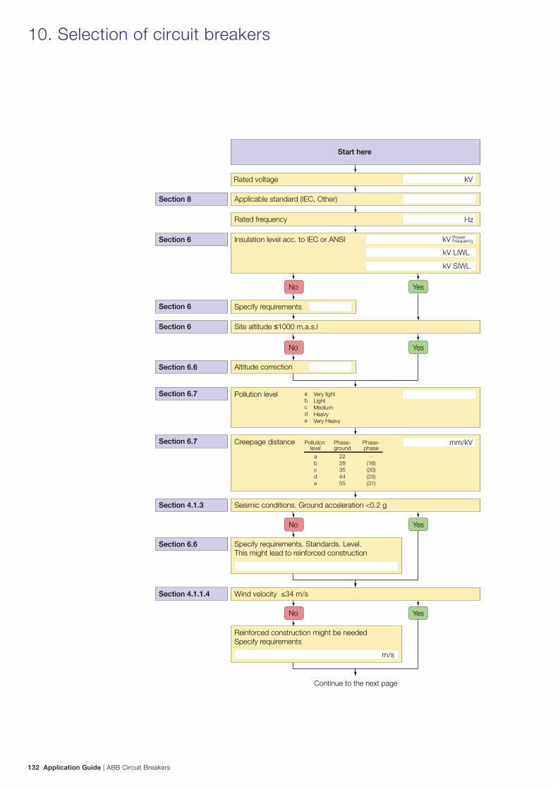
132 Application Guide | ABB Circuit Breakers
10. Selection of circuit breakers
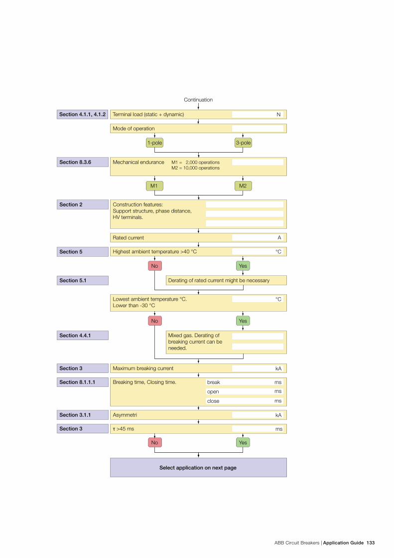
ABB Circuit Breakers | Application Guide 133
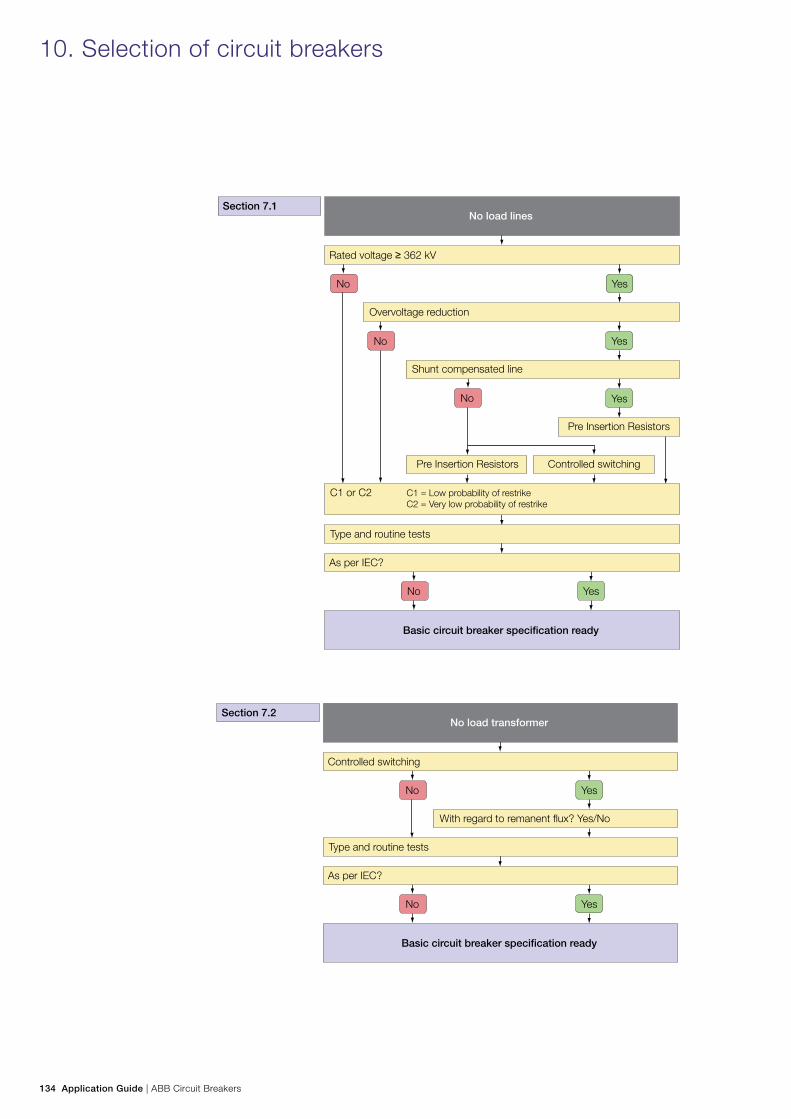
134 Application Guide | ABB Circuit Breakers
10. Selection of circuit breakers
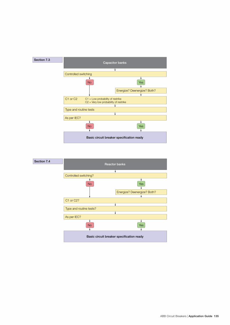
ABB Circuit Breakers | Application Guide 135
Contact us
Pub
licat
ion
1HS
M 9
543
23-0
2en,
Edi
tion
1.2,
201
3-02
Liv
e Ta
nk C
ircui
t Bre
aker
s, A
pplic
atio
n G
uideABB AB
High Voltage Products SE-771 80 LUDVIKA, SWEDEN Phone: +46 (0)240 78 20 00 Fax: +46 (0)240 78 36 50 E-Mail: [email protected] www.abb.comwww.abb.com/highvoltage
©Copyright 2013 ABB. All rights reserved
NOTE! ABB AB is working continuously to improve
the products. We therefore reserve the right to change
designs, dimensions and data without prior notice.