Embed Size (px)
Citation preview
htt
p:/
/ww
w.h
ach
.ulg
.ac.
be
Sophia Antipolis, France2 - 4 juin / 2 – 4 June
1D NUMERICAL APPROACH TO MODEL THE FLOW OVER A PIANO KEY WEIR (PKW)
S. Erpicum, O.Machiels, P. Archambeau, B. Dewals*, M. Pirotton
Research unit HACH, Department ArGEnCo, University of Liege (Belgium)*F.R.S.-FNRS – Belgian National Fund for Scientific Research
email: [email protected]
4th June 2010
htt
p:/
/ww
w.h
ach
.ulg
.ac.
be
Sophia Antipolis, France2 - 4 juin / 2 – 4 June
Introduction Modeling principles Math/num model ConclusionsApplications
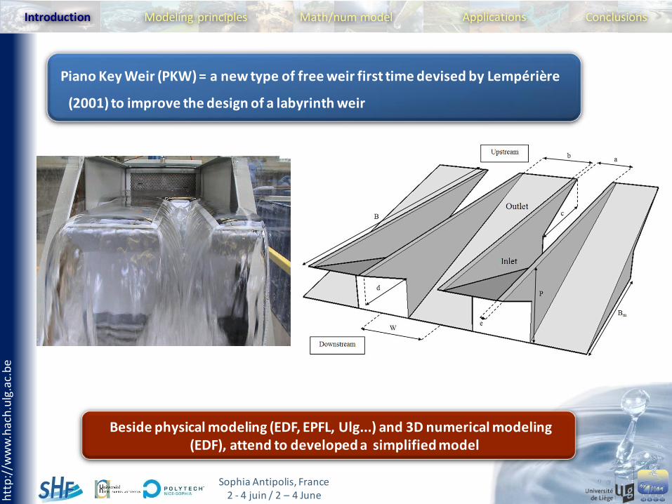
Beside physical modeling (EDF, EPFL, Ulg...) and 3D numerical modeling(EDF), attend to developed a simplified model
Piano Key Weir (PKW) = a new type of free weir first time devised by Lempérière
(2001) to improve the design of a labyrinth weir
htt
p:/
/ww
w.h
ach
.ulg
.ac.
be
Sophia Antipolis, France2 - 4 juin / 2 – 4 June
Introduction Modeling principles Math/num model ConclusionsApplications
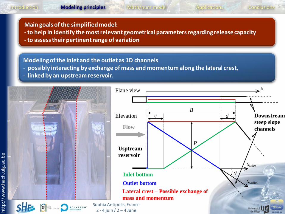
Main goals of the simplified model: - to help in identify the most relevant geometrical parameters regarding release capacity- to assess their pertinent range of variation
Modeling of the inlet and the outlet as 1D channels- possibly interacting by exchange of mass and momentum along the lateral crest, - linked by an upstream reservoir.
Figure 2: Basic element of a PKW (left) and numerical model layout with main geometric parameters (right)
Inlet bottom
Outlet bottom
Lateral crest – Possible exchange of
mass and momentum
Downstream
steep slope
channels
Usptream
reservoir
B
P
c d
Flow
Plane view
Elevation
x
xoutlet
xinlet
htt
p:/
/ww
w.h
ach
.ulg
.ac.
be
Sophia Antipolis, France2 - 4 juin / 2 – 4 June
Introduction Modeling principles Math/num model ConclusionsApplications
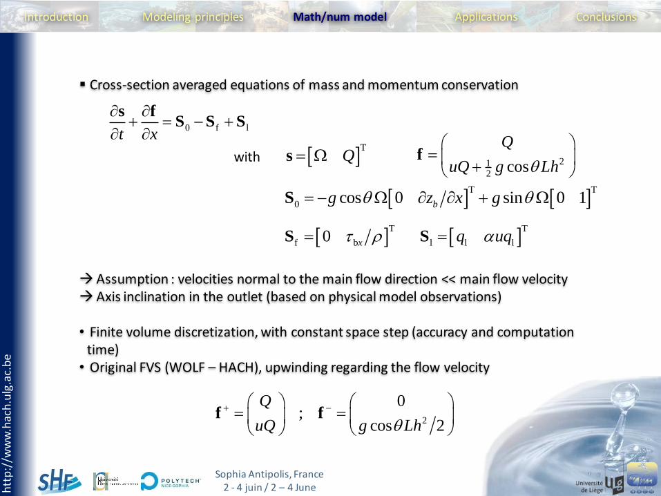
Cross-section averaged equations of mass and momentum conservation
Assumption : velocities normal to the main flow direction << main flow velocityAxis inclination in the outlet (based on physical model observations)
• Finite volume discretization, with constant space step (accuracy and computation time)
• Original FVS (WOLF – HACH), upwinding regarding the flow velocity
0 f lt x
s fS S S
T
Q s 212
cos
Q
uQ g Lh
f
T T
0 cos 0 sin 0 1bg z x g S
T
f b0 x S T
l l lq uqS
with
2
0;
cos 2
Q
uQ g Lh
f f
htt
p:/
/ww
w.h
ach
.ulg
.ac.
be
Sophia Antipolis, France2 - 4 juin / 2 – 4 June
Introduction Modeling principles Math/num model ConclusionsApplications
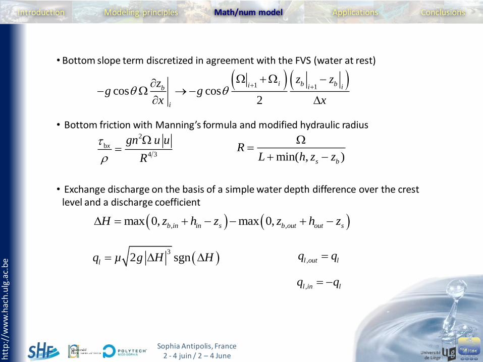
• Bottom slope term discretized in agreement with the FVS (water at rest)
• Bottom friction with Manning’s formula and modified hydraulic radius
• Exchange discharge on the basis of a simple water depth difference over the crest level and a discharge coefficient
1 1cos cos
2
i b bi i ib
i
z zzg g
x x
2
b
4 3
xgn u u
R
min( , )s b
RL h z z
, ,max 0, max 0,b in in s b out out sH z h z z h z
3
2 sgnlq µ g H H
,l in lq q
,l out lq q
htt
p:/
/ww
w.h
ach
.ulg
.ac.
be
Sophia Antipolis, France2 - 4 juin / 2 – 4 June
Introduction Modeling principles Math/num model ConclusionsApplications
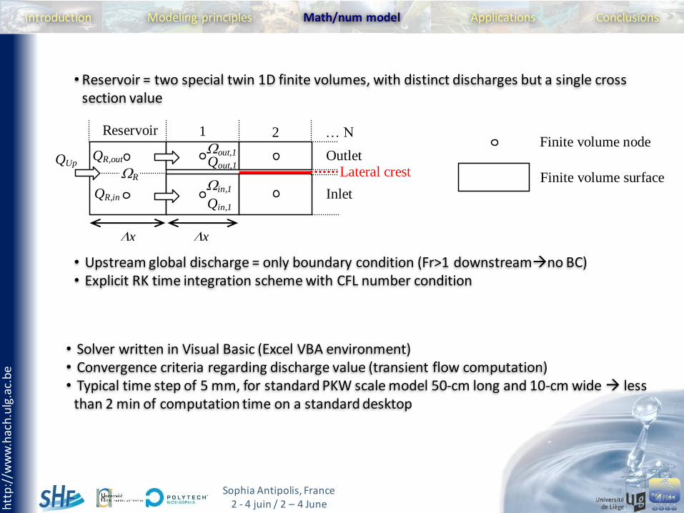
• Reservoir = two special twin 1D finite volumes, with distinct discharges but a single cross section value
• Upstream global discharge = only boundary condition (Fr>1 downstreamno BC)• Explicit RK time integration scheme with CFL number condition
Figure 3: Modeling of the upstream reservoir and links with the inlet and the outlet
Reservoir 1 2 … N
Outlet
Inlet
Lateral crest QUp QR,out
Finite volume surface
Finite volume node
x x
QR,in
R Qout,1
Qin,1
out,1
in,1
• Solver written in Visual Basic (Excel VBA environment)• Convergence criteria regarding discharge value (transient flow computation)• Typical time step of 5 mm, for standard PKW scale model 50-cm long and 10-cm wide less
than 2 min of computation time on a standard desktop
htt
p:/
/ww
w.h
ach
.ulg
.ac.
be
Sophia Antipolis, France2 - 4 juin / 2 – 4 June
Introduction Modeling principles Math/num model Conclusions
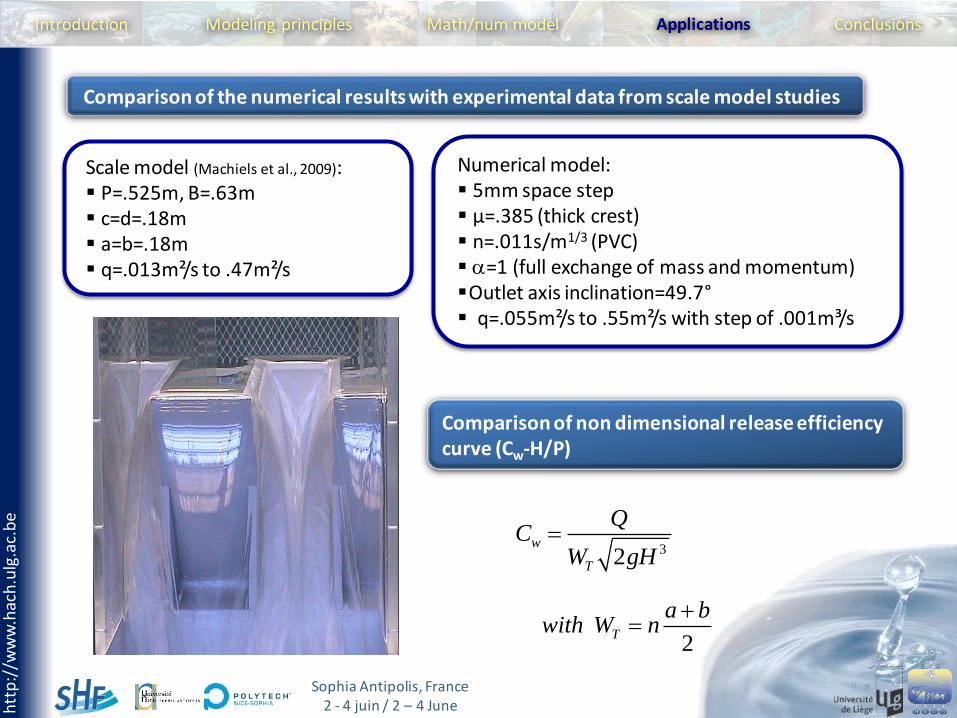
Numerical model: 5mm space step µ=.385 (thick crest) n=.011s/m1/3 (PVC) =1 (full exchange of mass and momentum)Outlet axis inclination=49.7° q=.055m²/s to .55m²/s with step of .001m³/s
Applications
Comparison of the numerical results with experimental data from scale model studies
Scale model (Machiels et al., 2009): P=.525m, B=.63m c=d=.18m a=b=.18m q=.013m²/s to .47m²/s
32w
T
QC
W gH
Comparison of non dimensional release efficiency curve (Cw-H/P)
2T
a bwith W n
htt
p:/
/ww
w.h
ach
.ulg
.ac.
be
Sophia Antipolis, France2 - 4 juin / 2 – 4 June
Introduction Modeling principles Math/num model ConclusionsApplications
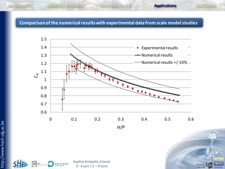
Comparison of the numerical results with experimental data from scale model studies
0.6
0.7
0.8
0.9
1
1.1
1.2
1.3
1.4
1.5
0 0.1 0.2 0.3 0.4 0.5 0.6
Cw
H/P
Experimental results
Numerical results
Numerical results +/-10%
htt
p:/
/ww
w.h
ach
.ulg
.ac.
be
Sophia Antipolis, France2 - 4 juin / 2 – 4 June
Introduction Modeling principles Math/num model ConclusionsApplications
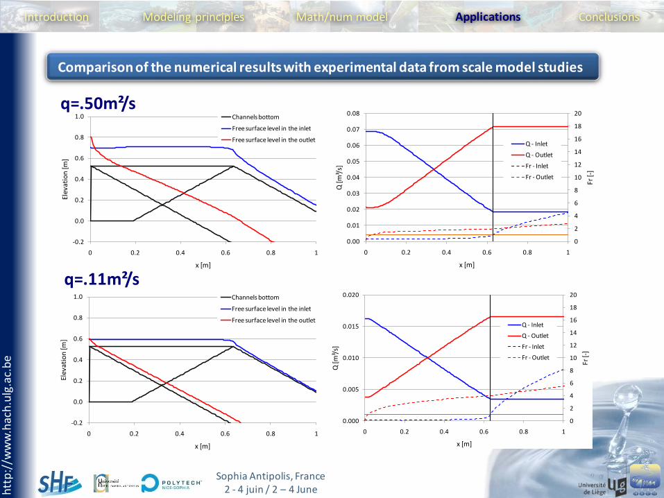
Comparison of the numerical results with experimental data from scale model studies
0
2
4
6
8
10
12
14
16
18
20
0.000
0.005
0.010
0.015
0.020
0 0.2 0.4 0.6 0.8 1
Fr [-
]
Q [m
³/s]
x [m]
Q - Inlet
Q - Outlet
Fr - Inlet
Fr - Outlet
-0.2
0.0
0.2
0.4
0.6
0.8
1.0
0 0.2 0.4 0.6 0.8 1
Elev
atio
n [m
]
x [m]
Channels bottom
Free surface level in the inlet
Free surface level in the outlet
0
2
4
6
8
10
12
14
16
18
20
0.00
0.01
0.02
0.03
0.04
0.05
0.06
0.07
0.08
0 0.2 0.4 0.6 0.8 1
Fr [-
]
Q [m
³/s]
x [m]
Q - Inlet
Q - Outlet
Fr - Inlet
Fr - Outlet
-0.2
0.0
0.2
0.4
0.6
0.8
1.0
0 0.2 0.4 0.6 0.8 1
Elev
atio
n [m
]
x [m]
Channels bottom
Free surface level in the inlet
Free surface level in the outlet
q=.50m²/s
q=.11m²/s
htt
p:/
/ww
w.h
ach
.ulg
.ac.
be
Sophia Antipolis, France2 - 4 juin / 2 – 4 June
Introduction
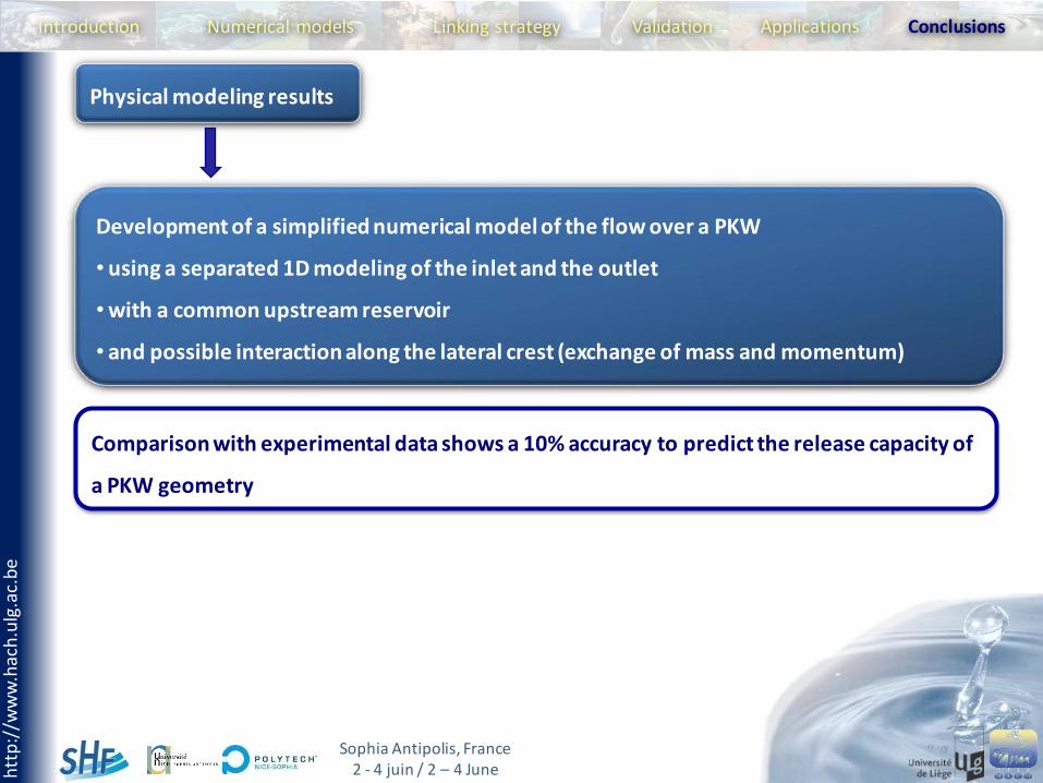
Comparison with experimental data shows a 10% accuracy to predict the release capacity of
a PKW geometry
Development of a simplified numerical model of the flow over a PKW
• using a separated 1D modeling of the inlet and the outlet
• with a common upstream reservoir
• and possible interaction along the lateral crest (exchange of mass and momentum)
Physical modeling results
Numerical models ValidationLinking strategy ConclusionsApplications
htt
p:/
/ww
w.h
ach
.ulg
.ac.
be
Sophia Antipolis, France2 - 4 juin / 2 – 4 June
Introduction
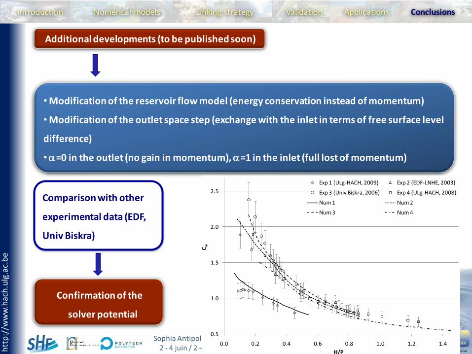
Comparison with other
experimental data (EDF,
Univ Biskra)
• Modification of the reservoir flow model (energy conservation instead of momentum)
• Modification of the outlet space step (exchange with the inlet in terms of free surface level
difference)
•=0 in the outlet (no gain in momentum), =1 in the inlet (full lost of momentum)
Additional developments (to be published soon)
Numerical models ValidationLinking strategy ConclusionsApplications
0.5
1.0
1.5
2.0
2.5
0.0 0.2 0.4 0.6 0.8 1.0 1.2 1.4
Cw
H/P
Exp 1 (ULg-HACH, 2009) Exp 2 (EDF-LNHE, 2003)
Exp 3 (Univ Biskra, 2006) Exp 4 (ULg-HACH, 2008)
Num 1 Num 2
Num 3 Num 4
Confirmation of the
solver potential