Embed Size (px)
Citation preview
2
Steel Bridge Design
BDDMSP560 and SP250Electronic Shop DrawingsMathCAD WorksheetsLesson Learned

3
BDDMAASHTO (bolted field splice connections)NCHRP 12-79Shear ConnectorsNo weight limit, check with fabricatorsSteel members cast in concreteRecoating of existing Metal StructuresCross FramesModular Steel Bridge Workshop
4
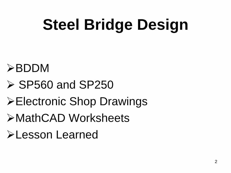
LRFD Specifications C6.13.6.1.4aFor a flexural member, it is recommended that the smaller section at the point of splice be taken as the side of the splice that has the flange with the smallest nominal flexural resistance.
Replaced with:For flexural members, it is recommended that the smaller section at the point of splice be taken as the side of the splice that has the smaller calculated moment of inertia for the noncomposite steel section.

5
BDDMAASHTO (bolted field splice connections)NCHRP 12-79Shear ConnectorsNo weight limit, check with fabricatorsSteel members cast in concreteRecoating of existing Metal StructuresCross FramesModular Steel Bridge Workshop

6
Out of plumb Web

7
BDDMAASHTO (bolted field splice connections)NCHRP 12-79Shear ConnectorsNo weight limit, check with fabricatorsSteel members cast in concreteRecoating of existing Metal StructuresCross FramesModular Steel Bridge Workshop

8
Shear Connectors, BDDM 1.2.1.7
Flange thickness transition not shown

9
BDDMAASHTO (bolted field splice connections)NCHRP 12-79Shear ConnectorsNo weight limit, check with fabricatorsSteel members cast in concreteRecoating of existing Metal StructuresModular Steel Bridge Workshop

10
BDDMAASHTO (bolted field splice connections)NCHRP 12-79Shear ConnectorsNo weight limit, check with fabricatorsSteel members cast in concreteRecoating of existing Metal StructuresCross FramesModular Steel Bridge Workshop

11
BDDM Figure 1.2.1.10C

12
BDDMAASHTO (bolted field splice connections)NCHRP 12-79Shear ConnectorsNo weight limit, check with fabricatorsSteel members cast in concreteRecoating of existing Metal StructuresCross FramesModular Steel Bridge Workshop

13
BDDM 1.2.4.5 (new section) “Process for recoating of an existing metal structure”
• Check latest load rating• Check last inspection report• Check for missed rivet or bolt• Consider remedy for structural deficiencies• Consider bolts and rivets outside normal
paint area

14
BDDMAASHTO (bolted field splice connections)NCHRP 12-79Shear ConnectorsNo weight limit, check with fabricatorsSteel members cast in concreteRecoating of existing Metal StructuresCross FramesModular Steel Bridge Workshop

15
Cross FramesCross Frames at Bents
BDDM, Fig1.2.1.6

16
Cross FramesCross Frames at Bents
AASHTO LRFD 6.7.4.2 I-Section Members
“Diaphragms or cross-frames are not required along skewed interior supports if diaphragms or cross-frames normal to the girders are provided at bearings that resist lateral forces.”
17
Cross FramesCross Frames at BentsIntermediate Cross Frames
Differential deflection

18
1.2.1.3 Intermediate Cross Frames
Do not stagger intermediate cross frames in skewed or curved steel plate girders where two adjacent steel plate girders have significant differential deflection. Where two adjacent plate girders have significant differential deflection, such as the first row of cross frame from the end bents, do not use the “K” or “X” type of cross frames. Use details similar to Figure 1.2.1.13B.

19
Figure 1.2.1.13B

20
Cross FramesCross Frames at BentsIntermediate Cross Frames
Differential deflectionBox girders

21
BDDMAASHTO (bolted field splice connections)NCHRP 12-79Shear ConnectorsNo weight limit, check with fabricatorsSteel members cast in concreteCross FramesModular Steel Bridge Workshop

22
Modular Steel Bridge WorkshopOBJECTIVE:
• Develop a plan that will enable us to place the modular steel bridges into mainstream.
TARGET OUTCOMES:• A list of practical concepts of modular steel bridges• Recommendations to develop a design detailing manual
fabrication• Recommendations to develop fabrication and
construction guidelines• Recommendations to develop a testing requirement plan• Recommendations for owners, fabricators, industry,
academia

23
Owner’s Perspective
• Methods to provide rapid construction with no sacrifices in quality, redundancy,continuity, and future maintenance costs
• Ability to replace the deck in the future• Details that are acceptable for seismic
regions

24
Fabricator’s Perspective promising concepts that High Steel has been investigating. They include:• Full depth pre-topped composite decked girders• Partial depth pre-topped composite sub-deck girder units• Modular orthotropic steel deck girder systems• Decked steel tub girders

25
Modular Steel Bridge Workshop
Pre-topped Composite Decked Girders

26
Rapid Construction using steel stringer/girder systems
Report of Current PracticeDescription:Two different types of steel stringer systems were
discussed. The two systems include:• Multi-span girders designed as simple span for
dead load and continuous for live load• Multi-span girders designed as continuous for all
loads, but spliced at interior piers.• Pre-topped deck/girder systems

27
Rapid Construction using steel stringer/girder systems
Report of Current PracticeLead Team Members:
– Ed Wasserman (Tennessee DOT)– Hormoz Seradj (Oregon DOT)– Dennis Mertz (University of Delaware)– Richard Sause (Lehigh University)– Karl Frank (University of Texas)– Atorod Azizinamini (University of Nebraska,
Lincoln)

28
Steel Bridge Design
BDDMSP560 and SP250Electronic Shop DrawingsLesson Learned

29
Steel Erection claims00560.46 Erection:a) General - Erect the metalwork, remove
temporary construction and do all work required to complete the structure(s), including the removal of the old structure(s) according to Section 00501, if specified.
b) Methods and Equipment - Before starting the erection work, the erection method proposed and the amount and character of equipment to be used will be reviewed. This review will not relieve the Contractor of the responsibility for the safety of the method or equipment, or from carrying out the work in full accordance with the plans and specifications. Do not perform work until approval has been obtained.

30
• 00560.46 Erection: continued
c) Field Inspection and Testingd) Handling and Storing Materialse) Bearings and Anchoragesf) Pin Connectiong) Misfits
Steel Erection claims

31
Temporary Detour Bridges, SP25000250.10 Material - Provide material for temporary detour bridges according to the applicable Sections of Part 00500.
Quality of Material, Section 00165

32
Backfill Material 00510.10, 00510.11, 00510.12, 0510.13
Drilled Shafts 00512.10, 00512.12, 00512.13, 00512.14, 00512.15, 00512.18
Piling 00520.10
Steel Reinforcement 00530.10, 00530.11, 00530.12, 00530.13, 00530.14
Resin Bonded Anchor Systems 00535.10
Structural Concrete 00540.10, 00540.11, 00540.14, 00540 .15

33
Reinforced Concrete Bridge End Panel
00545.10
Post-Tensioning 00555.10, 00555.11, 00555,12, 555.13
Structural Steel 00560.10
Timber Structures 00570.10, 00570,11, 00570.13, 00570.13
Bridge Bearings 00582.10
Bridge Rails 00587.10

34
Temporary Detour Bridges00250.43 Construction - Construct temporary detour bridges according to the applicable Sections of Part 00500, the requirements of applicable permitting agencies and the following:
• Weld structural steel according to AWS D1.5
• Weld steel piling according to AWS D1.1
35
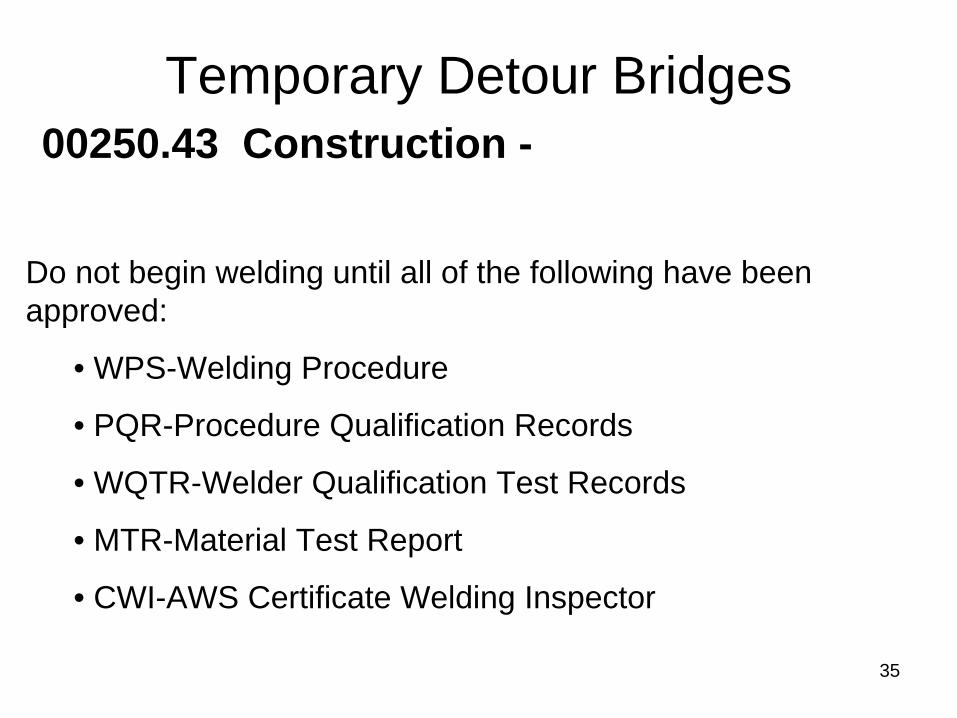
Temporary Detour Bridges
Do not begin welding until all of the following have been approved:
• WPS-Welding Procedure
• PQR-Procedure Qualification Records
• WQTR-Welder Qualification Test Records
• MTR-Material Test Report
• CWI-AWS Certificate Welding Inspector
00250.43 Construction -

36
Steel Bridge Design
BDDMSP560 and SP250Electronic Shop DrawingsMathCAD WorksheetsLesson Learned

37

38

39
Steel Bridge Design
BDDMSP560 and SP250Electronic Shop DrawingsMathCAD WorksheetsLesson Learned

40
MathCAD Worksheets
Deck Design
Filed Splice Connection Design
Bearing Design

41
Steel Bridge Design
BDDMSP560 and SP250Electronic Shop DrawingsMathCAD WorksheetsLesson Learned

42
Workmanship

43
Workmanship
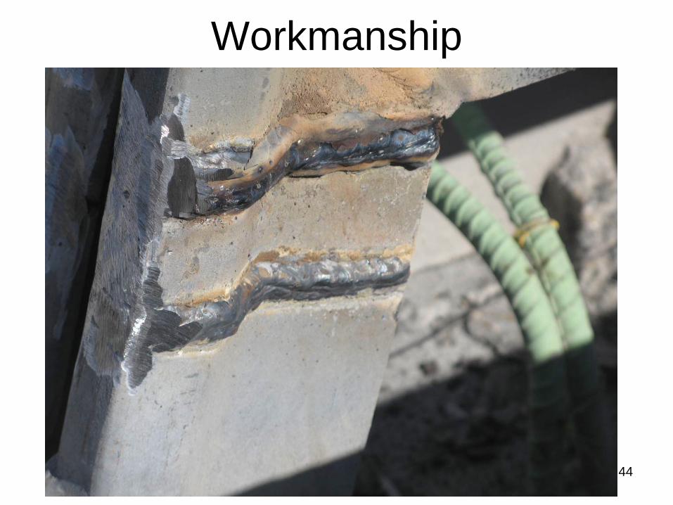
44
Workmanship
45
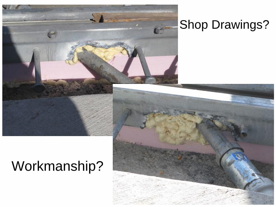
Workmanship?
Shop Drawings?

46
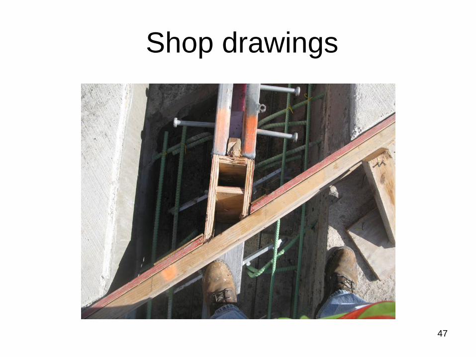
Shop drawings
47
Shop drawings

48
Shop drawings

49
Anchor Detail BR. 145

50
Long span Bridges

51
Buldging

52

53

54

55
Disk Bearings

56
57
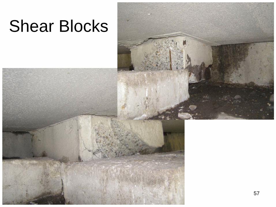
Shear Blocks

58
New Bridge

59
New Bridge

60

61
Question?