Embed Size (px)
Citation preview

1.9E PRG
I-Joist Compatible Depths
Framing Lumber Depths
Full 3 1/2" and 5 1/2" Widths
One Piece Installation
Balanced Lay-up with No Camber
Excellent Fire Performance

8 0 0 . 2 2 1 . 2 3 2 6 w w w . a n t h o n y f o r e s t . c o m
ANTHONY FOREST PRODUCTS
Canfor is one of the world’s largest producers of sustainable lumber, pulp and paper and is also a North American leader in green energy production. We’ve built our reputation on the quality of our products, the reliability of our supply and our superior customer service.
Canfor Southern Pine Inc., headquartered in Mobile, Alabama, is the operating company for all of Canfor’s operations in the southern United States.
Canfor’s presence in the US dates back to 2006 and has continued to grow over the past decade. This includes the 2015 acquisition of Anthony Forest Products Company LLC and its sawmill in Urbana, Arkansas and engineered wood laminating plants in El Dorado, Arkansas and Washington, Georgia.
The Urbana sawmill has undergone considerable capital improvements over the past couple of years to increase production and efficiencies. It has increased the volume of quality laminating stock along with the other Canfor Southern Pine sawmills to ensure both glulam plants are fully integrated with an uninterrupted supply of laminating stock lumber from our own sawmills.
Not only has our sawmill diversified with changing markets, our laminating plants have diversified to create new products like PRG® to meet customer demands.
NEW DESIGN VALUESThe lowering of design values for visually graded Southern Pine lumber on June 1, 2013 opened up new opportunities for Anthony Power Products® like PRG®. Shorter spans for dimension lumber and built up lumber headers and beams gave way to more PRG®, Power Beam®, and stock 24F glulam being used in the same project. Although Southern Pine visual design values were reduced effecting lumber spans, Anthony Forest Products glulam Power Products® were not affected by lower design values since special grading rules and MSR machines are in place to mechanically grade the lumber.
POWER PRODUCTS® CERTIFIED BY SFI The Sustainable Forestry Initiative® (SFI) program is a comprehensive system of principles, objectives, and performance measures developed by professional foresters, conservationists and scientists, among others that combines the perpetual growing and harvesting of trees with the
long term protection of wildlife, plants, soil and water quality. There are currently close to 285 million acres/115 million hectares of forestland in North America enrolled in the SFI® program, making it among the world’s largest sustainable forestry programs.
Lion's Club Golf Course Club House
SFI Beam Stamp
PRG® Beam End Tag
APA PRG® Stamp

8 0 0 . 2 2 1 . 2 3 2 6 w w w . a n t h o n y f o r e s t . c o m
SOFTWARE All Power Products®, like PRG®, can be sized for loading and spans using our free Power Sizer® software downloadable from our website or from the load tables on pages 5, 6 and 7. For sizes not shown in this brochure, use our Power Sizer® software or 24F Glulam brochure.
TECHNICAL SUPPORTIf you need technical assistance, a skilled member of the Anthony EWP Team can be reached at 800.221.2326, 870-862-3414 or at [email protected].
WARRANTY Power Products® are warranted for the life of the structure against defects in materials and workmanship. We guarantee prompt and courteous customer service. For a detailed copy of our limited warranty, call us at 800.221.2326 or visit our website at www.anthonyforest.com to download a copy.
Austin, Texas
Georgia Laminating Plant

8 0 0 . 2 2 1 . 2 3 2 6 w w w . a n t h o n y f o r e s t . c o m
• Protect the glulam products from direct exposure to weather
conditions (i.e. sun, wind, rain, snow) by storing under cover
or by leaving the paper wrap intact until they are installed.
• Store on stickers or racks above ground moisture and in
orderly stacks at heights that may be handled safely.
• Use care in moving and storing with forklifts to prevent
damage with forks.
• To minimize checking, seal ends of beams after trimming
or cutting.
• Do not install damaged glulam. Notify Anthony Forest
Products or your local distributor for assistance.
• Once beams are installed, remove protective wrap. Allow
them to gradually season and adjust to the temperature and
moisture conditions of the structure.
• Do not directly expose glulam members to rapid changes in
moisture and temperature, typical of temporary heating units.
Such exposure may result in excessive surface checking.
In the field, glulam is subject to humidity and moisture that can affect critical size tolerance and appearance. To maintain the dimensional stability and minimize checking of beams, each beam is surface sealed with a special protective wax emulsion coating for wood.
Our sealers are environmentally friendly, water-based products that help to stabilize the moisture content of wood. Not only does the seal protect the glulam from environmental moisture, but it allows the glulam to adjust to the environment slowly.
PRG® should be stored and handled in accordance with the following guidelines to maximize performance and to minimize necessary field adjustments.
HANDLING & STORAGE
CANFOR
SOUTHERN
PINEMADE
IN
USA
Arkansas Laminating Plant

8 0 0 . 2 2 1 . 2 3 2 6 w w w . a n t h o n y f o r e s t . c o m
• Full 3 ½” and 5 ½” widths at IJC depths for flush framing• Easily substitutable for SCL in most applications• Eliminates the issues of cupped and/or swollen SCL• Fast, easy one piece installation with conventional wood framing tools• Takes the confusion out of proper connections of multi-ply SCL or lumber
• Readily available and an economical alternative to other engineered wood products• Balanced layup makes PRG® a natural choice for simple, multi and cantilever span applications• PRG® falls under the building code category of heavy timber, therefore, it has excellent fire performance• Free Power Sizer® software for easy to use single member sizing
Code Evaluations/Standards: APA ICC-ESR 1940, ANSI/APA A190.1 and ASTM D-3737.
AFP Power Sizer® Software: An easy-to-use structural analysis program of sizing AFP Power Products®. Power Products® data bases also included in Mitek Sapphire, iStruct™ and Alpine Software.
Quality Assurance: Power Rated Glulam is manufactured in accordance with ANSI/APA A190.1 (Structural Glued
Laminated Timber) with appropriate modifications. Plant implemented Total Quality Management, statistical process control procedures and APA-The Engineered Wood Association as our third party quality assurance program; ensures consistent quality and performance in every Power Rated Glulam.
Warranty: All Power Rated Glulam are covered under a limited lifetime warranty.
WHY POWER RATED GLULAM?
20' SpanGrade
MOE x 106 - Fb 18' SpanProduct
14' Span 16' Span 18' Span 20' Span
3 1/2" x 11 7/8" 3 1/2" x 14"
PRG®/SCL Load Comparison Table1 (LDF = 1.00)(Total Load/Live Load in PLF)
SCL 2.0 - 3100 779/527 518/353 360/248 259/181 590/407 430/296
SCL 2.0 - 2900 723/490 489/334 344/237 250/174 560/382 409/282
SCL 1.9 - 2600 685/465 475/325 330/228 236/165 537/368 387/267
PRG® 1.9 - 2400 661/475 467/318 325/223 234/163 537/366 388/267
LSL 1.75 1.8 - 2500 628/428 424/290 296/203 214/152 484/334 352/246
1Notes:• Three grades of SCL shown representing majority range of USA production.• PRG® within 90% of allowable total load comparison for deflection and 80+% on bending control with all SCL shown.• When drawing in PRG®, the same size PRG® works for the same size SCL 90% of the time.• Bottom Line - PRG® comes in at lower installed cost.

8 0 0 . 2 2 1 . 2 3 2 6 w w w . a n t h o n y f o r e s t . c o m
9 1/4 8.5 231 9,982 11,479 12,478 6,475 7,446 8,094 9 1/2 8.8 250 10,858 12,487 13,573 6,650 7,648 8,313 11 1/4 10.4 415 15,099 17,364 18,874 7,875 9,056 9,844 3 1/2 11 7/8 11.0 489 16,791 19,310 20,989 8,316 9,563 10,395 14 12.9 800 23,128 26,597 28,910 9,800 11,270 12,250 16 14.8 1,195 30,007 34,508 37,509 11,200 12,880 14,000 18 16.6 1,701 37,800 43,470 47,250 12,600 14,490 15,750 9 1/4 13.4 363 15,686 18,039 19,608 10,175 11,701 12,719 9 1/2 13.8 393 16,681 19,183 20,851 10,450 12,018 13,063 11 1/4 16.3 653 23,133 26,603 28,916 12,375 14,231 15,469 5 1/2 11 7/8 17.2 768 25,585 29,423 31,981 13,068 15,028 16,335 14 20.3 1,258 35,532 40,862 44,415 15,400 17,710 22,138 16 23.2 1,877 46,400 53,360 58,000 17,600 20,240 25,300 18 26.1 2,673 58,725 67,534 73,406 19,800 22,770 24,750
Weight Moment of Width (in.) Depth (in.) (lbf/ft.)1 Inertia (in4) 100% 115% 125% 100% 115% 125%
PRG 24F-1.9E Dry-Use Fb=2,400 psi Fv=300psi E=1.9 x 10⁶ psi FC =740 psiPower Rated Glulam Section Properties and Allowable Capacities
Maximum Resistive Moment (ft.-lbf)2 Maximum Resistive Shear (lbf)
1.9E POWER RATED GLULAM (PRG®)
(1) The tabulated E values include True E (also known as "shear free" E), apparent E, and E for beam stability calculation (NDS 3.4.3.8). For calculating beam deflections, the tabulated Eapp
values shall be used unless the shear deflection is determined in addition to bending deflection based on the tablulated Etrue.
The axial modulus of elasticity, Eaxial and Eaxial min, shall be equal to the tabulated Ey true and Ey min values.
(2) Fb shall be adjusted by the volume effect factor using the following formula: Cv = (5.125/b)1/20 x (12/d)1/20 x (21/L)1/20 ≤ 1.0 where: b = beam width (in.) d = beam depth (in.) L = beam length (ft.) (3) Power Rated Glulam combination symbol is 24F-V5M1 SYP, balanced layup and no camber.
(1) Beam weight is assumed to be 38 pcf.(2) Maximum resistive moment shall be adjusted by the volume factor in foot note 2 for spans over 21'. All spans under 21’ have already been adjusted to the volume effect factor above.
Modulus of Elasticity (106 psi)1
Compression Perpendicular
to Grain Fc (psi)Grade True Apparent
BeamStability
Horizontal ShearFv (psi)Product Tension Zone Compression
Zone
Flexural Stress Fb (psi)2
Power Rated Glulam Design Properties
Power Rated Glulam3 (PRG) 1.9 E 1.9 1.8 0.95 2,400 2,400 300 740
31/2
51/2

8 0 0 . 2 2 1 . 2 3 2 6 w w w . a n t h o n y f o r e s t . c o m
VERTICAL 1/2" DIAMETER HOLES IN GLULAM BEAMS
*TECHNICAL NOTE
FIELD NOTCHING AND DRILLING OF GLUED LAMINATED TIMBER BEAMSEWS S560H • NOVEMBER 2014Please download Technical Note at www.anthonyforest.com
Figure 1. Hole in Glulam Beam
While field-drilling vertical holes in glulam beams should be
avoided, there are situations where they may be required. This
Technical Note* provides guidance on the drilling of a single 1/2"
vertical hole in simple span glulam beams of various thicknesses.
These recommendations are based on a "worst case" scenario
that assumes the beam is placed at its maximum span and is fully
loaded with uniformly distributed loads. Concentrated or other
non-uniform loads have not been considered, and for such loads
or other situations, the effect of drilling a vertical hole should be
checked by a qualified design professional.
Drilling the hole:These holes must be carefully drilled along the vertical axis of the
beam. (See Figure 1.) If the beam is deep, it is recommended to
use a drill guide and a sharp bit to preclude the bit from wandering
as it passes through the beam depth. In addition, the beam should
be inspected at the possible hole location to ensure that there are
no knots, knot-holes, finger joints or other allowable defects in
the vicinity of the hole (within the width of the beam on either side
of the hole).
Arkansas Laminating Plant

8 0 0 . 2 2 1 . 2 3 2 6 w w w . a n t h o n y f o r e s t . c o m
Notes:1. The maximum size horizontal hole (through the width of the beam) should not exceed 1 1/2 inches. Larger hole may be possible; contact our sales office for customer support. 2. Edge and End Spacing: Any horizontal hole must be a minimum of 4 hole diameters from the top or bottom surface of the glued laminated timber member and 8 hole diameters from the member ends. The distance is measured from the edge of the member to the centerline of the hole.
3. Spacing between holes: Field added open or access holes not shown on the contract drawings shall be a minimum of 8 hole diameters from any hole in the member. The distance is measured from the edge of the hole to the nearest edge of the existing hole.
4. Number of holes: Determine the number of field added holes allowed by allowing one hole per each 5 foot length of the member. (This rule does not apply to spacing of holes.)
L = length of beam d = depth of beam
TYPICAL CONNECTIONS
DO NOT DRILL IN CRITICAL ZONESUNIFORMLY LOADED SINGLE SPAN BEAM GLUED LAMINATED TIMBER
GUIDELINES FOR DRILLING HORIZONTAL HOLES
8 0 0 . 2 2 1 . 2 3 2 6 w w w . a n t h o n y f o r e s t . c o m
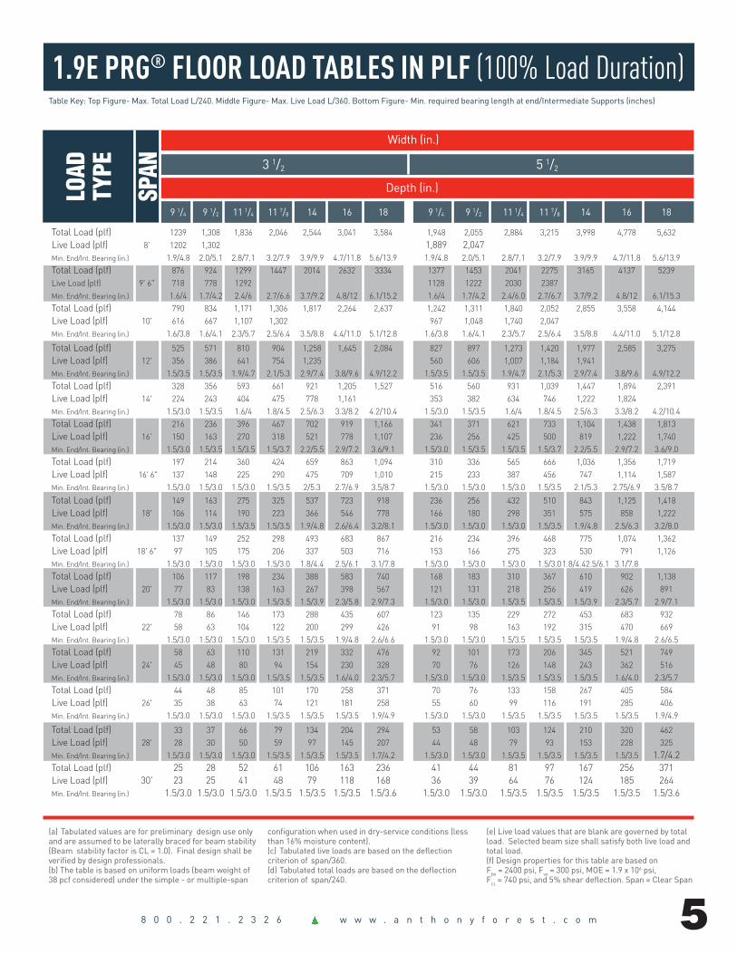
1.9E PRG® FLOOR LOAD TABLES IN PLF (100% Load Duration)
SPAN
(a) Tabulated values are for preliminary design use only and are assumed to be laterally braced for beam stability (Beam stability factor is CL = 1.0). Final design shall be verified by design professionals. (b) The table is based on uniform loads (beam weight of 38 pcf considered) under the simple - or multiple-span
configuration when used in dry-service conditions (less than 16% moisture content).(c) Tabulated live loads are based on the deflection criterion of span/360. (d) Tabulated total loads are based on the deflection criterion of span/240.
(e) Live load values that are blank are governed by total load. Selected beam size shall satisfy both live load and total load. (f) Design properties for this table are based on Fbx = 2400 psi, Fvx = 300 psi, MOE = 1.9 x 10⁶ psi, Fc = 740 psi, and 5% shear deflection. Span = Clear Span
Table Key: Top Figure- Max. Total Load L/240. Middle Figure- Max. Live Load L/360. Bottom Figure- Min. required bearing length at end/Intermediate Supports (inches)
LOAD
TY
PE Width (in.) 3 1/2 5 1/2 Depth (in.) 9 1/4 9 1/2 11 1/4 11 7/8 14 16 18 9 1/4 9 1/2 11 1/4 11 7/8 14 16 18
Total Load (plf) 1239 1,308 1,836 2,046 2,544 3,041 3,584 1,948 2,055 2,884 3,215 3,998 4,778 5,632 Live Load (plf) 8' 1202 1,302 1,889 2,047 Min. End/Int. Bearing (in.) 1.9/4.8 2.0/5.1 2.8/7.1 3.2/7.9 3.9/9.9 4.7/11.8 5.6/13.9 1.9/4.8 2.0/5.1 2.8/7.1 3.2/7.9 3.9/9.9 4.7/11.8 5.6/13.9 Total Load (plf) 876 924 1299 1447 2014 2632 3334 1377 1453 2041 2275 3165 4137 5239 Live Load (plf) 9' 6" 718 778 1292 1128 1222 2030 2387 Min. End/Int. Bearing (in.) 1.6/4 1.7/4.2 2.4/6 2.7/6.6 3.7/9.2 4.8/12 6.1/15.2 1.6/4 1.7/4.2 2.4/6.0 2.7/6.7 3.7/9.2 4.8/12 6.1/15.3 Total Load (plf) 790 834 1,171 1,306 1,817 2,264 2,637 1,242 1,311 1,840 2,052 2,855 3,558 4,144 Live Load (plf) 10' 616 667 1,107 1,302 967 1,048 1,740 2,047 Min. End/Int. Bearing (in.) 1.6/3.8 1.6/4.1 2.3/5.7 2.5/6.4 3.5/8.8 4.4/11.0 5.1/12.8 1.6/3.8 1.6/4.1 2.3/5.7 2.5/6.4 3.5/8.8 4.4/11.0 5.1/12.8
Total Load (plf) 525 571 810 904 1,258 1,645 2,084 827 897 1,273 1,420 1,977 2,585 3,275 Live Load (plf) 12' 356 386 641 754 1,235 560 606 1,007 1,184 1,941 Min. End/Int. Bearing (in.) 1.5/3.5 1.5/3.5 1.9/4.7 2.1/5.3 2.9/7.4 3.8/9.6 4.9/12.2 1.5/3.5 1.5/3.5 1.9/4.7 2.1/5.3 2.9/7.4 3.8/9.6 4.9/12.2 Total Load (plf) 328 356 593 661 921 1,205 1,527 516 560 931 1,039 1,447 1,894 2,391 Live Load (plf) 14' 224 243 404 475 778 1,161 353 382 634 746 1,222 1,824 Min. End/Int. Bearing (in.) 1.5/3.0 1.5/3.5 1.6/4 1.8/4.5 2.5/6.3 3.3/8.2 4.2/10.4 1.5/3.0 1.5/3.5 1.6/4 1.8/4.5 2.5/6.3 3.3/8.2 4.2/10.4 Total Load (plf) 216 236 396 467 702 919 1,166 341 371 621 733 1,104 1,438 1,813 Live Load (plf) 16' 150 163 270 318 521 778 1,107 236 256 425 500 819 1,222 1,740 Min. End/Int. Bearing (in.) 1.5/3.0 1.5/3.5 1.5/3.5 1.5/3.7 2.2/5.5 2.9/7.2 3.6/9.1 1.5/3.0 1.5/3.5 1.5/3.5 1.5/3.7 2.2/5.5 2.9/7.2 3.6/9.0 Total Load (plf) 197 214 360 424 659 863 1,094 310 336 565 666 1,036 1,356 1,719 Live Load (plf) 16' 6" 137 148 225 290 475 709 1,010 215 233 387 456 747 1,114 1,587 Min. End/Int. Bearing (in.) 1.5/3.0 1.5/3.0 1.5/3.0 1.5/3.5 2/5.3 2.7/6.9 3.5/8.7 1.5/3.0 1.5/3.0 1.5/3.0 1.5/3.5 2.1/5.3 2.75/6.9 3.5/8.7
Total Load (plf) 149 163 275 325 537 723 918 236 256 432 510 843 1,125 1,418 Live Load (plf) 18' 106 114 190 223 366 546 778 166 180 298 351 575 858 1,222 Min. End/Int. Bearing (in.) 1.5/3.0 1.5/3.0 1.5/3.5 1.5/3.5 1.9/4.8 2.6/6.4 3.2/8.1 1.5/3.0 1.5/3.0 1.5/3.0 1.5/3.5 1.9/4.8 2.5/6.3 3.2/8.0 Total Load (plf) 137 149 252 298 493 683 867 216 234 396 468 775 1,074 1,362 Live Load (plf) 18' 6" 97 105 175 206 337 503 716 153 166 275 323 530 791 1,126 Min. End/Int. Bearing (in.) 1.5/3.0 1.5/3.0 1.5/3.0 1.5/3.0 1.8/4.4 2.5/6.1 3.1/7.8 1.5/3.0 1.5/3.0 1.5/3.0 1.5/3.0 1.8/4.42.5/6.1 3.1/7.8 Total Load (plf) 106 117 198 234 388 583 740 168 183 310 367 610 902 1,138 Live Load (plf) 20' 77 83 138 163 267 398 567 121 131 218 256 419 626 891 Min. End/Int. Bearing (in.) 1.5/3.0 1.5/3.0 1.5/3.0 1.5/3.5 1.5/3.9 2.3/5.8 2.9/7.3 1.5/3.0 1.5/3.0 1.5/3.5 1.5/3.5 1.5/3.9 2.3/5.7 2.9/7.1 Total Load (plf) 78 86 146 173 288 435 607 123 135 229 272 453 683 932 Live Load (plf) 22' 58 63 104 122 200 299 426 91 98 163 192 315 470 669 Min. End/Int. Bearing (in.) 1.5/3.0 1.5/3.0 1.5/3.0 1.5/3.5 1.5/3.5 1.9/4.8 2.6/6.6 1.5/3.0 1.5/3.0 1.5/3.5 1.5/3.5 1.5/3.5 1.9/4.8 2.6/6.5 Total Load (plf) 58 63 110 131 219 332 476 92 101 173 206 345 521 749 Live Load (plf) 24' 45 48 80 94 154 230 328 70 76 126 148 243 362 516 Min. End/Int. Bearing (in.) 1.5/3.0 1.5/3.0 1.5/3.0 1.5/3.5 1.5/3.5 1.6/4.0 2.3/5.7 1.5/3.0 1.5/3.0 1.5/3.5 1.5/3.5 1.5/3.5 1.6/4.0 2.3/5.7 Total Load (plf) 44 48 85 101 170 258 371 70 76 133 158 267 405 584 Live Load (plf) 26' 35 38 63 74 121 181 258 55 60 99 116 191 285 406 Min. End/Int. Bearing (in.) 1.5/3.0 1.5/3.0 1.5/3.0 1.5/3.5 1.5/3.5 1.5/3.5 1.9/4.9 1.5/3.0 1.5/3.0 1.5/3.5 1.5/3.5 1.5/3.5 1.5/3.5 1.9/4.9
Total Load (plf) 33 37 66 79 134 204 294 53 58 103 124 210 320 462 Live Load (plf) 28' 28 30 50 59 97 145 207 44 48 79 93 153 228 325 Min. End/Int. Bearing (in.) 1.5/3.0 1.5/3.0 1.5/3.0 1.5/3.5 1.5/3.5 1.5/3.5 1.7/4.2 1.5/3.0 1.5/3.0 1.5/3.5 1.5/3.5 1.5/3.5 1.5/3.5 1.7/4.2 Total Load (plf) 25 28 52 61 106 163 236 41 44 81 97 167 256 371 Live Load (plf) 30' 23 25 41 48 79 118 168 36 39 64 76 124 185 264 Min. End/Int. Bearing (in.) 1.5/3.0 1.5/3.0 1.5/3.0 1.5/3.5 1.5/3.5 1.5/3.5 1.5/3.6 1.5/3.0 1.5/3.0 1.5/3.5 1.5/3.5 1.5/3.5 1.5/3.5 1.5/3.6

8 0 0 . 2 2 1 . 2 3 2 6 w w w . a n t h o n y f o r e s t . c o m
1.9E PRG® ROOF LOAD TABLES IN PLF (115% Load Duration) SHEAR DESIGN EQUATIONS FOR NOTCHED & TAPERED BEAMS
(a) Tabulated values are for preliminary design use only and are assumed to be laterally braced for beam stability (Beam stability factor is CL = 1.0). Final design shall be verified by design professionals. (b) The table is based on uniform loads (beam weight of 38 pcf considered) under the simple - or multiple-span
configuration when used in dry-service conditions (less than 16% moisture content).(c) Tabulated live loads are based on the deflection criterion of span/240. (d) Tabulated total loads are based on the deflection criterion of span/180.
(e) Live load values that are blank are governed by total Load. Selected beam size shall satisfy both live load and total load.(f) Design properties for this table are based on Fbx = 2400 psi, Fvx = 300 psi, MOE = 1.9 x 10⁶ psi, Fc = 740 psi, and 5% shear deflection. Span = Clear Span
LOAD
TY
PE
SPAN
Table Key: Top Figure- Max. Total Load L/180. Middle Figure- Max. Live Load L/240. Bottom Figure- Min. required bearing length at end/Intermediate Supports (inches)
Width (in.) 3 1/2 5 1/2 Depth (in.) 9 1/4 9 1/2 11 1/4 11 7/8 14 16 18 9 1/4 9 1/2 11 1/4 11 7/8 14 16 18
Total Load (plf) 1,426 1,505 2,113 2,355 2,928 3,499 4,124 2,242 2,365 3,319 3,700 4,601 5,498 6,481 Live Load (plf) 8' Min. End/Int. Bearing (in.) 2.2/5.5 2.3/5.8 3.7/8.2 3.7/9.1 4.5/11.4 5.4/13.6 6.4/16.0 2.2/5.5 2.3/5.85 3.7/8.2 3.7/9.1 4.5/11.4 5.4/13.6 6.4/16.0 Total Load (plf) 1,009 1,064 1,495 1,666 2,318 3,030 3,836 1,586 1,673 2,349 2,618 3,643 4,761 6,029 Live Load (plf) 9' 6" Min. End/Int. Bearing (in.) 1.9/4.6 2/4.9 2.7/6.9 3/7.6 4.3/10.6 5.6/14 7/17.5 1.9/4.6 2/4.9 2.7/6.9 3/7.6 4.3/10.6 5.6/14 7/17.6 Total Load (plf) 909 960 1,348 1,503 2,091 2,606 3,035 1,430 1,509 2,119 2,362 3,287 4,095 4,769 Live Load (plf) 10' Min. End/Int. Bearing (in.) 1.8/4.4 1.9/4.7 2.6/6.5 2.9/7.3 4.1/10.2 5.1/12.6 5.9/14.7 1.8/4.4 1.9/4.7 2.6/6.5 2.9/7.3 4.1/10.2 5.1/12.6 5.9/14.7 Total Load (plf) 629 664 933 1,041 1,449 1,894 2,399 989 1,044 1,466 1,635 2,276 2,977 3,770 Live Load (plf) 12' 534 579 840 910 Min. End/Int. Bearing (in.) 1.5/3.6 1.6/3.9 2.2/5.4 2.4/6.1 3.4/8.5 4.4/11.1 5.6/14.0 1.5/3.7 1.6/3.9 2.2/5.4 2.4/6.1 3.4/8.5 4.4/11.1 5.6/14.0 Total Load (plf) 440 478 683 762 1,061 1,388 1,759 692 751 1,073 1,197 1,667 2,181 2,754 Live Load (plf) 14' 337 365 605 712 529 573 951 1,119 Min. End/Int. Bearing (in.) 1.5/3.0 1.5/3.5 1.9/4.6 2.1/5.2 2.9/7.3 3.8/9.5 4.8/12.0 1.5/3.0 1.5/3.5 1.9/4.6 2.1/5.2 2.9/7.3 3.8/9.5 4.8/11.9 Total Load (plf) 292 317 521 581 810 1,059 1,343 459 499 810 913 1,272 1,657 2,088 Live Load (plf) 16' 225 244 406 477 782 254 384 637 750 1,228 Min. End/Int. Bearing (in.) 1.5/3.0 1.5/3.5 1.6/4 1.8/4.6 2.5/6.3 3.3/8.3 4.2/10.5 1.5/3.0 1.5/3.5 1.6/4 1.8/4.6 2.5/6.3 3.3/8.3 4.2/10.4 Total Load (plf) 265 288 483 545 760 994 1,260 418 453 759 857 1,194 1,563 1,981 Live Load (plf) 16' 6" 206 223 370 435 713 323 350 581 683 1,120 Min. End/Int. Bearing (in.) 1.5/3.0 1.5/3.0 1.6/3.9 1.75/4.3 2.4/6 3.2/8 4/10.1 1.5/3 1.5/3 1.6/3.9 1.8/4.4 2.5/6 3.2/8 4.0/10.0 Total Load (plf) 202 220 370 436 637 834 1,058 319 346 581 686 997 1,297 1,635 Live Load (plf) 18' 158 172 285 335 549 819 249 270 448 526 863 1,288 Min. End/Int. Bearing (in.) 1.5/3.0 1.5/3.0 1.5/3.3 1.6/3.9 2.3/5.6 2.9/7.4 3.7/9.3 1.5/3.0 1.5/3.5 1.5/3.3 1.6/3.9 2.2/5.6 2.9/7.3 3.7/9.2 Total Load (plf) 185 202 340 400 602 788 999 293 317 534 629 946 1,239 1,571 Live Load (plf) 18' 6" 146 158 262 309 506 755 229 248 412 485 795 1,186 Min. End/Int. Bearing (in.) 1.5/3 1.5/3 1.5/3.1 1.5/3.6 2.2/5.4 2.8/7 3.6/9 1.5/3 1.5/3 1.5/3 1.5/3.6 2.2/5.4 2.9/7 3.6/9 Total Load (plf) 145 158 267 315 514 673 854 229 249 419 495 800 1,041 1,313 Live Load (plf) 20' 115 125 208 244 400 597 851 181 196 326 384 629 939 Min. End/Int. Bearing (in.) 1.5/3 1.5/3.0 1.5/3.0 1.5/3.5 2.0/5.1 2.7/6.6 3.4/8.4 1.5/3 1.5/3.0 1.5/3.5 1.5/3.5 2.0/5.0 2.6/6.5 3.3/8.2 Total Load (plf) 107 117 198 234 389 554 700 169 184 311 368 611 852 1,075 Live Load (plf) 22' 87 94 156 183 301 449 639 136 148 245 288 472 705 1,004 Min. End/Int. Bearing (in.) 1.5/3 1.5/3.0 1.5/3.0 1.5/3.5 1.7/4.3 2.4/6.0 3.0/7.6 1.5/3 1.5/3.0 1.5/3.5 1.5/3.5 1.7/4.3 2.4/5.9 3.0/7.4 Total Load (plf) 80 88 150 178 297 447 583 127 139 236 280 466 702 896 Live Load (plf) 24' 67 72 120 141 232 346 492 105 114 189 222 364 543 773 Min. End/Int. Bearing (in.) 1.5/3 1.5/3.0 1.5/3.0 1.5/3.5 1.5/3.6 2.1/5.3 2.8/6.9 1.5/3 1.5/3.0 1.5/3.5 1.5/3.5 1.5/3.6 2.1/5.3 2.7/6.8 Total Load (plf) 61 68 116 138 231 349 493 97 106 182 217 362 548 756 Live Load (plf) 26' 53 57 95 111 182 272 387 83 89 149 175 286 427 608 Min. End/Int. Bearing (in.) 1.5/3 1.5/3.0 1.5/3.0 1.5/3.5 1.5/3.5 1.8/4.5 2.6/6.4 1.5/3 1.5/3 1.5/3.5 1.5/3.5 1.5/3.5 1.8/4.5 2.5/6.2 Total Load (plf) 47 52 91 108 182 276 398 75 82 143 170 286 434 625 Live Load (plf) 28' 42 46 76 89 146 218 310 66 72 119 140 229 342 487 Min. End/Int. Bearing (in.) 1.5/3 1.5/3.0 1.5/3.0 1.5/3.5 1.5/3.5 1.6/3.9 2.2/5.6 1.5/3 1.5/3.0 1.5/3.5 1.5/3.5 1.5/3.5 1.6/3.9 2.2/5.6 Total Load (plf) 37 40 72 86 146 222 320 59 65 113 135 229 349 503 Live Load (plf) 30' 34 37 62 72 119 177 252 54 58 97 114 186 278 396 Min. End/Int. Bearing (in.) 1.5/3 1.5/3.0 1.5/3.0 1.5/3.5 1.5/3.5 1.5/3.5 1.9/4.9 1.5/3 1.5/3.0 1.5/3.5 1.5/3.5 1.5/3.5 1.5/3.5 1.9/4.9

8 0 0 . 2 2 1 . 2 3 2 6 w w w . a n t h o n y f o r e s t . c o m
d
BearingLength
Lag screw extends past the neutral axis into the upper portion of the beam
(f ) Reinforcement Technique to Minimize Crack Propagation at the End Bearing Notches
Neutral Axis
Potentialcrack zoneUse one or more fully
threaded lag screws
Washer
O.1dDepth of notch <
or 3 inches whichever is less
*Power Sizer® Software can be used to evaluate notched slope cutting based on these formulas.
SHEAR DESIGN EQUATIONS FOR NOTCHED & TAPERED BEAMS

8 0 0 . 2 2 1 . 2 3 2 6 w w w . a n t h o n y f o r e s t . c o m
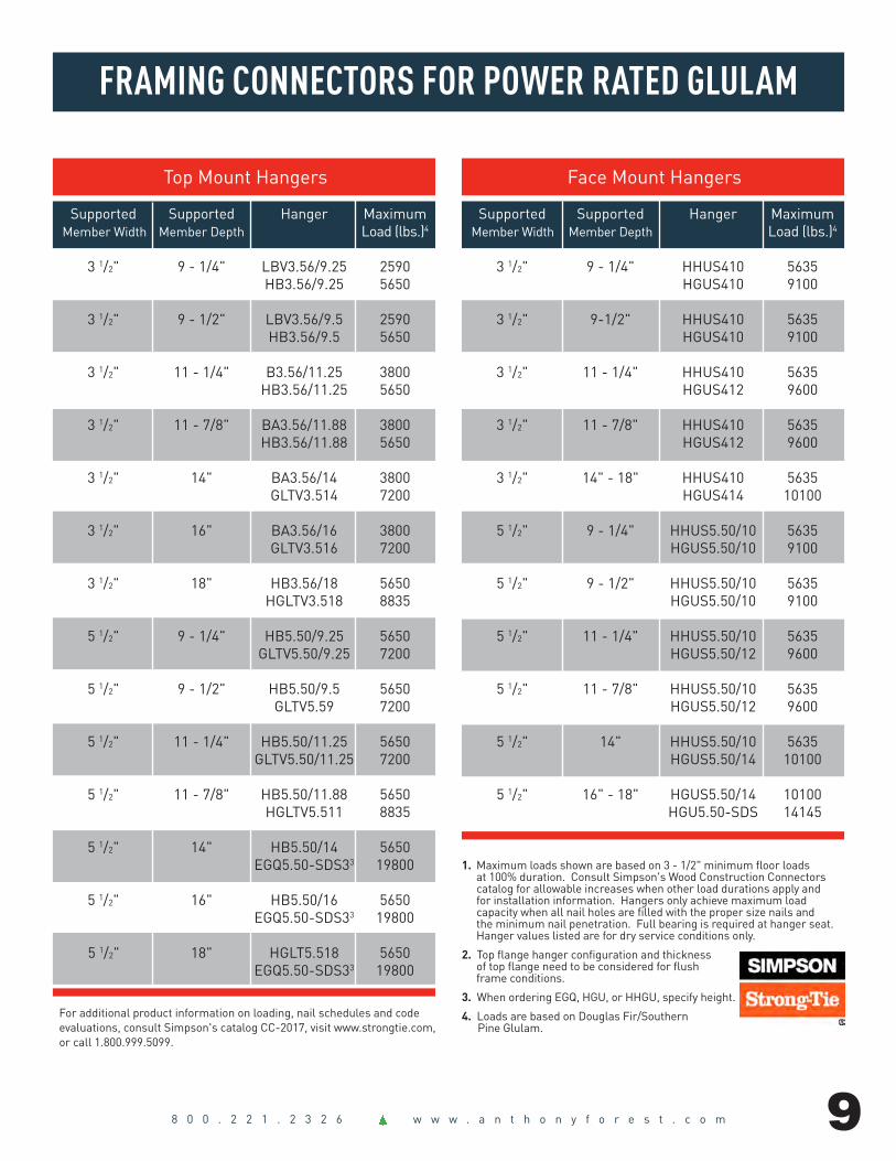
FRAMING CONNECTORS FOR POWER RATED GLULAM
Top Mount Hangers 1. Listed loads are based on hanger attachment to a glulam header.2. Uplift loads have been increased 60% for wind or seismic loads; no further increase shall be permitted.3. Top Mount Hangers require a minimum 3-1/2-in minimum header thickness. 4. Nails: 10d nails are 0.148-in dia. x 3-in long; NA16D-RS nails are 0.148-in dia. x 3-1/2-in long; 16d nails are 0.162-in dia. x 3-1/2-in long.
Top Mount Hangers3
Fastener Allowable Schedule4 Loads (lbs).1
USP Uplift2 Beam Size Stock No. Header Joist 100% 160%
For additional product information on loading, nail schedules, and code evaluations, consult USP’s Product Catalog, visit our website at www.USPconnectors.com, or call 1-800-328-5934.
Face Mount Hangers Fastener Allowable Schedule4 Loads (lbs).1
USP Uplift2
Beam Size Stock No. Header Joist 100% 125% 160%3 1/2" x 9 1/4"-14" THD410 (38) 16d (20) 10d 5145 5680 3435
THDH4103 (46) 16d (12) 16d 7190 7190 2620
3 1/2" x 14"-18" THD414 (58) 16d (20) 10d 5680 5680 3435
THDH4143 (66) 16d (16) 16d 9705 9705 3365
5 1/2" x 9 1/4"-11 7/8" THD610 (38) 16d (20) 10d 5750 6085 2730
THDH6103 (46) 16d (16) 16d 8295 8300 3365
5 1/2" x 14"-18" THD614 (58) 16d (20) 10d 6735 6735 3745
THDH6143 (66) 16d (22) 16d 9685 9685 4625
3 1/2" x 9 1/4" PHXU35925 (8) 16d (6) 10d 5285 1290
HLBH35925 (15) NA16D-RS (6) 16d 9600 1420
3 1/2" x 9 1/2" PHXU3595 (8) 16d (6) 10d 5285 1290
HLBH3595 (15) NA16D-RS (6) 16d 9600 1420
3 1/2" x 11 1/4" PHXU35112 (8) 16d (6) 10d 5285 1290
HLBH35112 (15) NA16D-RS (6) 16d 9600 1420
3 1/2" x 11 7/8" PHXU35118 (8) 16d (6) 10d 5285 1290
HLBH35118 (15) NA16D-RS (6) 16d 9600 1420
3 1/2" x 14" PHXU3514 (8) 16d (6) 10d 5285 1290
HLBH3514 (15) NA16D-RS (6) 16d 9600 1420
3 1/2" x 16" PHXU3516 (8) 16d (6) 10d 5285 1290
HLBH3516 (15) NA16D-RS (6) 16d 9600 1420
3 1/2" x 18" PHXU3518 (8) 16d (6) 10d 5285 1290
HLBH3518 (15) NA16D-RS (6) 16d 9600 1420
5 1/2" x 9 1/4" PHXU55925 (8) 16d (6) 10d 5285 1290
HLBH55925 (15) NA16D-RS (6) 16d 9600 1605
5 1/2" x 9 1/2" PHXU5595 (8) 16d (6) 10d 5285 1290
HLBH5595 (15) NA16D-RS (6) 16d 9600 1605
5 1/2" x 11 1/4" PHXU55112 (8) 16d (6) 10d 5285 1290
HLBH55112 (15) NA16D-RS (6) 16d 9600 1605
5 1/2" x 11 7/8" PHXU55118 (8) 16d (6) 10d 5285 1290
HLBH55118 (15) NA16D-RS (6) 16d 9600 1605
5 1/2" x 14" PHXU5514 (8) 16d (6) 10d 5285 1290
HLBH5514 (15) NA16D-RS (6) 16d 9600 1605
5 1/2" x 16" PHXU5516 (8) 16d (6) 10d 5285 1290
HLBH5516 (15) NA16D-RS (6) 16d 9600 1605
5 1/2" x 18" PHXU5518 (8) 16d (6) 10d 5285 1290
HLBH5518 (15) NA16D-RS (6) 16d 9600 1605
Face Mount Hangers1. Listed loads are based on hanger attachment to a glulam header.2. Uplift loads have been increased 60% for wind or seismic loads; no further increase shall be permitted.3. Full length joist nails need to be toenailed at a 30° to 45° angle to achieve listed loads for the THDH hangers. 4. Nails: 10d nails are 0.148-in dia. x 3-in long; 16d nails are 0.162-in dia. x 3-1/2-in long.

8 0 0 . 2 2 1 . 2 3 2 6 w w w . a n t h o n y f o r e s t . c o m
1.9E PRG® ROOF LOAD TABLES IN PLF (125% LOAD DURATION)
(a) Tabulated values are for preliminary design use only and are assumed to be laterally braced for beam stability (Beam stability factor is CL = 1.0). Final design shall be verified by design professionals. (b) The table is based on uniform loads (beam weight of 38 pcf considered) under the simple - or multiple-span
configuration when used in dry-service conditions (less than 16% moisture content). (c) Tabulated live loads are based on the deflection criterion of span/240. (d) Tabulated total loads are based on the deflection criterion of span/180.
e) Live load values that are blank are governed by total load. Selected beam size shall satisfy both live load and total load. (f) Design properties for this table are based on Fbx =2400psi, Fvx = 300 psi, MOE = 1.9 x 10⁶ psi, Fc = 740 psi, and 5% shear deflection. Span = Clear Span
Table Key: Top Figure- Max. Total Load L/180. Middle Figure- Max. Live Load L/240. Bottom Figure- Min. required bearing length at end/Intermediate Supports (inches)
SPAN
LOAD
TY
PE Width (in.) 3 1/2 5 1/2 Depth (in.) 9 1/4 9 1/2 11 1/4 11 7/8 14 16 18 9 1/4 9 1/2 11 1/4 11 7/8 14 16 18
Total Load (plf) 1,551 1,637 2,297 2,560 3,183 3,804 4,484 2,438 2,572 3,609 4,023 5,002 5,978 7,047 Live Load (plf) 8' Min. End/Int. Bearing (in.) 2.4/6 2.5/6.4 3.5/9 4.0/9.9 4.9/123 5.9/14.7 6.9/17.4 2.4/6 2.5/6.4 3.5/9 4.0/9.9 4.9/12.3 5.9/14.7 6.9/17.4 Total Load (plf) 1,097 1,547 1,626 1,812 2,521 3,294 4,171 1,725 1,819 2,555 2,848 3,962 5,177 6,556 Live Load (plf) 9' 6" 1,077 1,167 1,692 Min. End/Int. Bearing (in.) 2.0/5 2.8/7 4.2/10.5 4.7/11.7 6/14.6 7/17.4 7.6/19 2.0/5 2.1/5.3 3/7.5 3.3/8.3 4.6/11.6 6/15.1 7.7/19 Total Load (plf) 989 1,045 1,467 1,635 2,274 2,833 3,300 1,556 1,642 2,304 2,569 3,574 4,453 5,186 Live Load (plf) 10' 923 1,000 1,451 1,572 Min. End/Int. Bearing (in.) 2/4.8 2.0/5.1 2.8/7.1 3.2/7.9 4.4/11.0 5.5/13.7 6.4/16.0 2/4.5 2.0/5.1 3/7.1 3.2/7.9 4.4/11.0 5.5/13.7 6.4/16.0 Total Load (plf) 684 723 1,015 1,132 1,576 2,060 2,609 1,076 1,136 1,595 1,779 2,476 3,237 4,100 Live Load (plf) 12' 534 579 961 1,131 840 910 1,511 1,777 Min. End/Int. Bearing (in.) 1.6/4 1.7/4.2 2.4/5.6 2.6/6.6 3.7/9.2 4.8/12.0 6.1/15.2 1.6/4 1.7/4.2 2.4/5.9 2.6/6.6 3.7/9.2 4.8/12.0 6.1/15.2 Total Load (plf) 440 478 743 829 1,154 1,510 1,913 692 751 1,168 1,303 1,814 2,373 2,995 Live Load (plf) 14' 337 365 605 712 529 573 951 1,119 Min. End/Int. Bearing (in.) 1.5/3 1.5/3.5 2.1/5 2.3/5.7 3.2/7.9 4.1/10.3 5.2/13.0 1.5/3 1.5/3.5 2.1/5 2.3/5.7 3.2/7.9 4.1/10.3 5.2/13.0 Total Load (plf) 292 317 531 626 881 1,153 1,461 459 499 834 983 1,384 1,803 2,272 Live Load (plf) 16' 225 244 406 477 782 354 384 637 750 1,228 Min. End/Int. Bearing (in.) 1.5/3 1.5/3.5 1.7/4.1 2.0/4.9 2.8/6.9 3.6/9.0 4.6/11.4 1.5/3 1.5/3.5 1.6/4 2.0/4.9 2.8/6.9 3.6/9.0 4.5/11.3 Total Load (plf) 265 288 483 569 827 1,082 1,371 418 453 759 894 1,300 1,701 2,156 Live Load (plf) 16' 6" 206 223 370 435 713 1,064 323 350 581 683 1,120 1,672 Min. End/Int. Bearing (in.) 1.5/3 1.5/3 1.5/4 2/4.5 3.0/6.6 3.5/8.6 4.4/11 1.5/3 1.5/3 1.5/4 2/4.5 2.7/6.6 3.5/8.6 4.4/11 Total Load (plf) 202 220 370 436 694 908 1,151 319 346 581 686 1,086 1,412 1,779 Live Load (plf) 18' 158 172 285 335 549 819 249 270 448 526 863 1,288 Min. End/Int. Bearing (in.) 1.5/3 1.5/3.5 1.5/3.2 1.6/3.9 2.5/6.1 3.2/8.0 4.1/10.1 1.5/3 1.5/3.5 1.5/3.5 1.6/3.9 2.4/6.1 3.2/7.9 4.0/10.0 Total Load (plf) 185 202 340 400 655 858 1,087 293 317 534 629 1,030 1,348 1,710 Live Load (plf) 18' 6" 146 158 262 309 506 755 1,075 229 248 412 485 795 1,186 1,689 Min. End/Int. Bearing (in.) 1.5/3 1.5/3 1.5/3 1.5/3.6 2.4/6 3.1/7.7 4/9.8 1.5/3 1.5/3 1.5/3.5 1.5/3.6 2.4/6 3.1/7.7 3.9/9.7 Total Load (plf) 145 158 267 315 521 733 929 229 249 419 495 819 1,133 1,429 Live Load (plf) 20' 115 125 208 244 400 597 851 181 196 326 384 629 939 1,337 Min. End/Int. Bearing (in.) 1.5/3 1.5/3.5 1.5/3 1.5/3.5 2.1/5.2 2.9/7.2 3.6/9.1 1.5/3 1.5/3.5 1.5/3.5 1.5/3.5 2.1/5.2 2.8/7.1 3.6/8.9 Total Load (plf) 107 117 198 234 389 584 762 169 184 311 368 611 918 1,171 Live Load (plf) 22' 87 94 156 183 301 449 639 136 148 245 288 472 705 1,004 Min. End/Int. Bearing (in.) 1.5/3 1.5/3.5 1.5/3 1.5/3.5 1.7/4.3 2.5/6.4 3.3/8.3 1.5/3 1.5/3.5 1.5/3.5 1.5/3.5 1.7/4.3 2.5/6.4 3.2/8.1 Total Load (plf) 80 88 150 178 297 447 635 127 139 236 280 466 702 976 Live Load (plf) 24' 67 72 120 141 232 346 492 105 114 189 222 364 543 773 Min. End/Int. Bearing (in.) 1.5/3 1.5/3.5 1.5/3 1.5/3.5 1.5/3.6 2.1/5.3 3.0/7.5 1.5/3 1.5/3.5 1.5/3.5 1.5/3.5 1.5/3.6 2.1/5.3 2.9/7.4 Total Load (plf) 61 68 116 138 231 349 500 97 106 182 217 362 548 786 Live Load (plf) 26' 53 57 95 111 182 272 387 83 89 149 175 286 427 608 Min. End/Int. Bearing (in.) 1.5/3 1.5/3.5 1.5/3 1.5/3.5 1.5/3.5 1.8/4.5 2.6/6.5 1.5/3 1.5/3.5 1.5/3.5 1.5/3.5 1.5/3.5 1.8/4.5 2.6/6.5 Total Load (plf) 47 52 91 108 182 276 398 75 82 143 170 286 434 625 Live Load (plf) 28' 42 46 76 89 146 218 310 66 72 119 140 229 342 487 Min. End/Int. Bearing (in.) 1.5/3 1.5/3 1.5/3 1.5/3.5 1.5/3.5 1.6/3.9 2.2/5.6 1.5/3 1.5/3 1.5/3 1.5/3.5 1.5/3.5 1.6/3.9 2.2/5.6 Total Load (plf) 37 40 72 86 146 222 320 59 65 113 135 229 349 503 Live Load (plf) 30' 34 37 62 72 119 177 252 54 58 97 114 186 278 396 Min. End/Int. Bearing (in.) 1.5/3 1.5/3 1.5/3 1.5/3.5 1.5/3.5 1.5/3.5 1.9/4.9 1.5/3 1.5/3 1.5/3 1.5/3.5 1.5/3.5 1.5/3.5 1.9/4.9

8 0 0 . 2 2 1 . 2 3 2 6 w w w . a n t h o n y f o r e s t . c o m
PROCEDURES FOR USING SIMPLE SPAN BEAM TABLES
1. To size beams from the Floor and Roof PLF Tables, it is required to have the following. a. Live load determined by the governing Building Code b. The dead load c. The beam span or clear opening d. Span carried or tributary width
2. These tables may be used to size a simple span uniformly distributed loaded beam or to determine the maximum load capacity of a specific size glulam beam. The allowable loads shown in PLF tables include the beam weight. A simple span condition exists when the beam is supported on each end without overhangs. A continuous or cantilever loading application may require a balanced layup and an engineering or design review.
Garage Door Header: Single Story Example ProblemDetermine the header size for the conditions below.
Roof Load Conditions: Live (LL) = 30 psf Dead (DL) = 10 psfBuilding Width: = 24'Overhang: = 2'Header Actual Span (L): = 20'Formula: Total Load = (B/2+2') x (LL+DL) = total applied load in PLFLive Load = (B/2+2') x LL = total live load in PLFExample:Total Load = (24/2+2) x (30+10) = 560 PLFLive Load = (24/2+2) x 30 = 420 PLF
TO SIZE: 1. Go to allowable roof load tables on page 6. LDF = 1.15 and find the 20' actual span row.2. Using the top row, find a total load greater than 560 PLF (3 ½" x 16")3. Using the middle row, find a live load greater than 420 PLF. Beam to select: 3 ½" x 16" - 20' (bearing required = 3")
NOTES1. Local code may require an engineered system of wall bracing for wall sections less than 4’ in length adjacent to door openings. A glulam garage door header extended continuously over these shorter walls adjacent to the garage door opening is an integral part of these engineered systems.
2. If attic loading is anticipated, additional floor loading must be considered. Example: Add Floor LL = 25, DL = 10 Revised Total Load = 980 PLF, Live Load = 720 PLF (5 ½" x 16" required)
Window Headers
Floor Girder Beam
Roof Rafters
Garage Door Header
8 0 0 . 2 2 1 . 2 3 2 6 w w w . a n t h o n y f o r e s t . c o m
FRAMING CONNECTORS FOR POWER RATED GLULAM
Face Mount Hangers
Supported Supported Hanger MaximumMember Width Member Depth Load (lbs.)4
3 1/2" 9 - 1/4" HHUS410 5635 HGUS410 9100
3 1/2" 9-1/2" HHUS410 5635 HGUS410 9100
3 1/2" 11 - 1/4" HHUS410 5635 HGUS412 9600
3 1/2" 11 - 7/8" HHUS410 5635 HGUS412 9600
3 1/2" 14" - 18" HHUS410 5635 HGUS414 10100
5 1/2" 9 - 1/4" HHUS5.50/10 5635 HGUS5.50/10 9100
5 1/2" 9 - 1/2" HHUS5.50/10 5635 HGUS5.50/10 9100
5 1/2" 11 - 1/4" HHUS5.50/10 5635 HGUS5.50/12 9600
5 1/2" 11 - 7/8" HHUS5.50/10 5635 HGUS5.50/12 9600
5 1/2" 14" HHUS5.50/10 5635 HGUS5.50/14 10100
5 1/2" 16" - 18" HGUS5.50/14 10100 HGU5.50-SDS 14145
1. Maximum loads shown are based on 3 - 1/2" minimum floor loads at 100% duration. Consult Simpson's Wood Construction Connectors catalog for allowable increases when other load durations apply and for installation information. Hangers only achieve maximum load capacity when all nail holes are filled with the proper size nails and the minimum nail penetration. Full bearing is required at hanger seat. Hanger values listed are for dry service conditions only. 2. Top flange hanger configuration and thickness of top flange need to be considered for flush frame conditions.
3. When ordering EGQ, HGU, or HHGU, specify height.
4. Loads are based on Douglas Fir/Southern Pine Glulam.
For additional product information on loading, nail schedules and code evaluations, consult Simpson's catalog CC-2017, visit www.strongtie.com, or call 1.800.999.5099.
Top Mount Hangers
Supported Supported Hanger MaximumMember Width Member Depth Load (lbs.)4
3 1/2" 9 - 1/4" LBV3.56/9.25 2590 HB3.56/9.25 5650
3 1/2" 9 - 1/2" LBV3.56/9.5 2590 HB3.56/9.5 5650
3 1/2" 11 - 1/4" B3.56/11.25 3800 HB3.56/11.25 5650
3 1/2" 11 - 7/8" BA3.56/11.88 3800 HB3.56/11.88 5650
3 1/2" 14" BA3.56/14 3800 GLTV3.514 7200
3 1/2" 16" BA3.56/16 3800 GLTV3.516 7200
3 1/2" 18" HB3.56/18 5650 HGLTV3.518 8835
5 1/2" 9 - 1/4" HB5.50/9.25 5650 GLTV5.50/9.25 7200
5 1/2" 9 - 1/2" HB5.50/9.5 5650 GLTV5.59 7200
5 1/2" 11 - 1/4" HB5.50/11.25 5650 GLTV5.50/11.25 7200
5 1/2" 11 - 7/8" HB5.50/11.88 5650 HGLTV5.511 8835
5 1/2" 14" HB5.50/14 5650 EGQ5.50-SDS33 19800
5 1/2" 16" HB5.50/16 5650 EGQ5.50-SDS33 19800 5 1/2" 18" HGLT5.518 5650 EGQ5.50-SDS33 19800

1.9E PRG
Power Beam® Power Column® SYP Lumber Power Preserved Glulam®
309 North Washington El Dorado, AR 71730 800.221.2326 www.anthonyforest.com©Anthony Forest Products Company, LLC - 8/2017
Distributed by:
Certified Building Products
Power Beam®
SYP Lumber
Power Preserved Glulam®
Power Column®
Power Header®
Power Sizer® Software
POWER PRODUCTS ® FAMILY
Anthony ForestProducts Website
Follow Us OnFacebook!
PRG® Beam End Tag