Embed Size (px)
Citation preview

AUTUMN1997
The Official Publication of the
NATIONAL LOCKSMITHAUTOMOBILE ASSOCIATION™
1997 Ford Expedition XLT...............................................page 1
Director's Page ..................................................................page 3
BMW Ignition Removal After Attempted Theft ......page 18
1996 Toyota Avalon.........................................................page 22
1995 Lexus LS400 Alarm Reset.....................................page 36
™
1. This time out we take a look at the 1997 Ford Expedition XLT.
(Continued on page 4)
1997 Ford Expedition XLT
by Michael Hyde
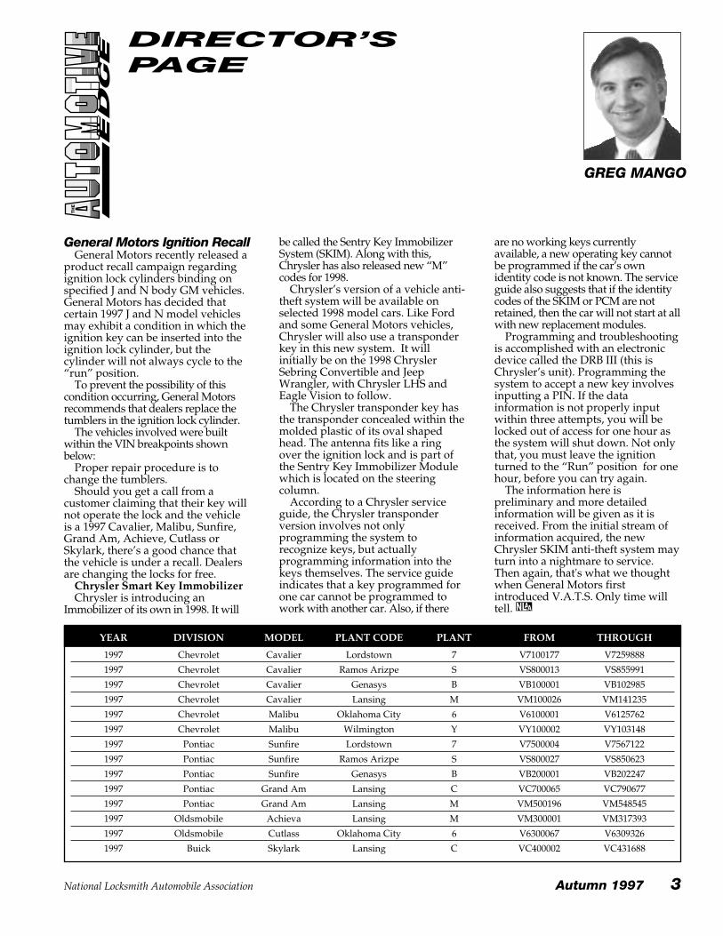
General Motors Ignition RecallGeneral Motors recently released a
product recall campaign regardingignition lock cylinders binding onspecified J and N body GM vehicles.General Motors has decided thatcertain 1997 J and N model vehiclesmay exhibit a condition in which theignition key can be inserted into theignition lock cylinder, but thecylinder will not always cycle to the“run” position.
To prevent the possibility of thiscondition occurring, General Motorsrecommends that dealers replace thetumblers in the ignition lock cylinder.
The vehicles involved were builtwithin the VIN breakpoints shownbelow:
Proper repair procedure is tochange the tumblers.
Should you get a call from acustomer claiming that their key willnot operate the lock and the vehicleis a 1997 Cavalier, Malibu, Sunfire,Grand Am, Achieve, Cutlass orSkylark, there’s a good chance thatthe vehicle is under a recall. Dealersare changing the locks for free.
Chrysler Smart Key ImmobilizerChrysler is introducing an
Immobilizer of its own in 1998. It will
be called the Sentry Key ImmobilizerSystem (SKIM). Along with this,Chrysler has also released new “M”codes for 1998.
Chrysler’s version of a vehicle anti-theft system will be available onselected 1998 model cars. Like Fordand some General Motors vehicles,Chrysler will also use a transponderkey in this new system. It willinitially be on the 1998 ChryslerSebring Convertible and JeepWrangler, with Chrysler LHS andEagle Vision to follow.
The Chrysler transponder key hasthe transponder concealed within themolded plastic of its oval shapedhead. The antenna fits like a ringover the ignition lock and is part ofthe Sentry Key Immobilizer Modulewhich is located on the steeringcolumn.
According to a Chrysler serviceguide, the Chrysler transponderversion involves not onlyprogramming the system torecognize keys, but actuallyprogramming information into thekeys themselves. The service guideindicates that a key programmed forone car cannot be programmed towork with another car. Also, if there
are no working keys currentlyavailable, a new operating key cannotbe programmed if the car’s ownidentity code is not known. The serviceguide also suggests that if the identitycodes of the SKIM or PCM are notretained, then the car will not start at allwith new replacement modules.
Programming and troubleshootingis accomplished with an electronicdevice called the DRB III (this isChrysler’s unit). Programming thesystem to accept a new key involvesinputting a PIN. If the datainformation is not properly inputwithin three attempts, you will belocked out of access for one hour asthe system will shut down. Not onlythat, you must leave the ignitionturned to the “Run” position for onehour, before you can try again.
The information here ispreliminary and more detailedinformation will be given as it isreceived. From the initial stream ofinformation acquired, the newChrysler SKIM anti-theft system mayturn into a nightmare to service.Then again, that's what we thoughtwhen General Motors firstintroduced V.A.T.S. Only time willtell.
DIRECTOR’SPAGE
GREG MANGO
YEAR DIVISION MODEL PLANT CODE PLANT FROM THROUGH
1997 Chevrolet Cavalier Lordstown 7 V7100177 V7259888
1997 Chevrolet Cavalier Ramos Arizpe S VS800013 VS855991
1997 Chevrolet Cavalier Genasys B VB100001 VB102985
1997 Chevrolet Cavalier Lansing M VM100026 VM141235
1997 Chevrolet Malibu Oklahoma City 6 V6100001 V6125762
1997 Chevrolet Malibu Wilmington Y VY100002 VY103148
1997 Pontiac Sunfire Lordstown 7 V7500004 V7567122
1997 Pontiac Sunfire Ramos Arizpe S VS800027 VS850623
1997 Pontiac Sunfire Genasys B VB200001 VB202247
1997 Pontiac Grand Am Lansing C VC700065 VC790677
1997 Pontiac Grand Am Lansing M VM500196 VM548545
1997 Oldsmobile Achieva Lansing M VM300001 VM317393
1997 Oldsmobile Cutlass Oklahoma City 6 V6300067 V6309326
1997 Buick Skylark Lansing C VC400002 VC431688
National Locksmith Automobile Association Autumn 1997 3
4 Autumn 1997 National Locksmith Automobile Association
1997 Ford Expedition XLT (continued from front cover)
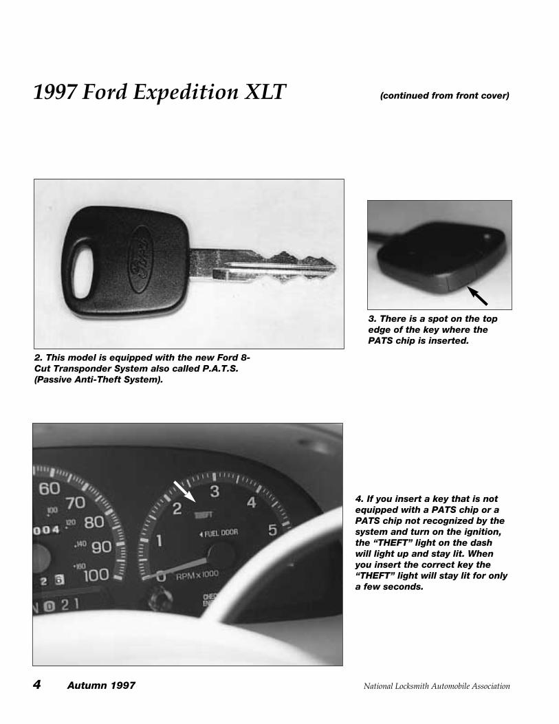
2. This model is equipped with the new Ford 8-Cut Transponder System also called P.A.T.S.(Passive Anti-Theft System).
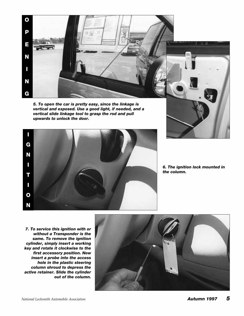
3. There is a spot on the topedge of the key where thePATS chip is inserted.
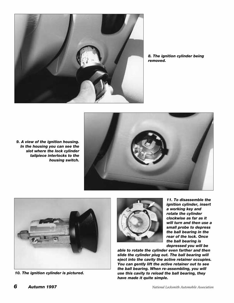
4. If you insert a key that is notequipped with a PATS chip or aPATS chip not recognized by thesystem and turn on the ignition,the “THEFT” light on the dashwill light up and stay lit. Whenyou insert the correct key the“THEFT” light will stay lit for onlya few seconds.
National Locksmith Automobile Association Autumn 1997 5
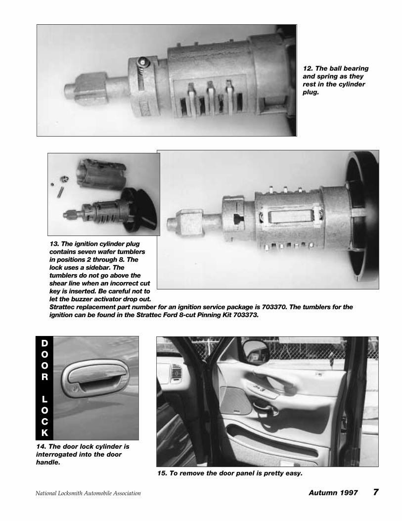
5. To open the car is pretty easy, since the linkage isvertical and exposed. Use a good light, if needed, and avertical slide linkage tool to grasp the rod and pullupwards to unlock the door.
O
P
E
N
I
N
G
6. The ignition lock mounted inthe column.
7. To service this ignition with orwithout a Transponder is thesame. To remove the ignition
cylinder, simply insert a workingkey and rotate it clockwise to the
first accessory position. Nowinsert a probe into the access
hole in the plastic steeringcolumn shroud to depress the
active retainer. Slide the cylinderout of the column.
I
G
N
I
T
I
O
N
6 Autumn 1997 National Locksmith Automobile Association
11. To disassemble theignition cylinder, inserta working key androtate the cylinderclockwise as far as itwill turn and then use asmall probe to depressthe ball bearing in therear of the lock. Oncethe ball bearing isdepressed you will be
able to rotate the cylinder even farther and thenslide the cylinder plug out. The ball bearing willeject into the cavity the active retainer occupies.You can gently lift the active retainer out to seethe ball bearing. When re-assembling, you willuse this cavity to reload the ball bearing, theyhave made it quite simple.
8. The ignition cylinder beingremoved.
9. A view of the ignition housing.In the housing you can see the
slot where the lock cylindertailpiece interlocks to the
housing switch.
10. The ignition cylinder is pictured.
13. The ignition cylinder plugcontains seven wafer tumblersin positions 2 through 8. Thelock uses a sidebar. Thetumblers do not go above theshear line when an incorrect cutkey is inserted. Be careful not tolet the buzzer activator drop out. Strattec replacement part number for an ignition service package is 703370. The tumblers for theignition can be found in the Strattec Ford 8-cut Pinning Kit 703373.
National Locksmith Automobile Association Autumn 1997 7
12. The ball bearingand spring as theyrest in the cylinderplug.
14. The door lock cylinder isinterrogated into the doorhandle.
DOOR
LOCK
15. To remove the door panel is pretty easy.
8 Autumn 1997 National Locksmith Automobile Association
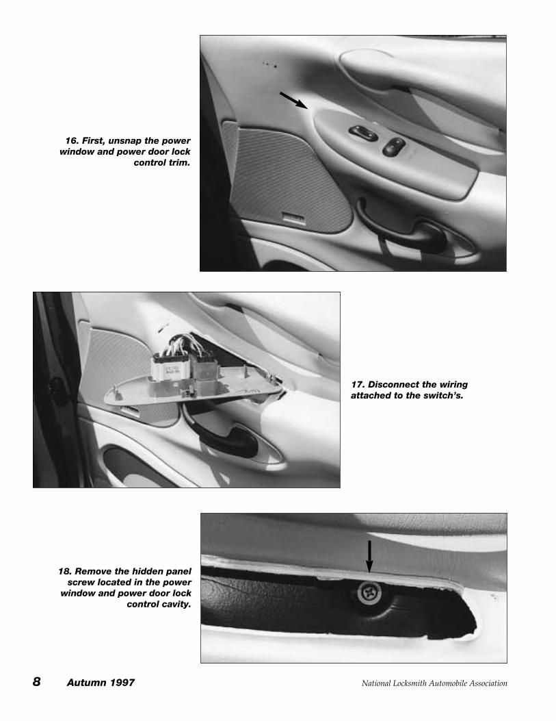
16. First, unsnap the powerwindow and power door lock
control trim.
17. Disconnect the wiringattached to the switch’s.
18. Remove the hidden panelscrew located in the power
window and power door lockcontrol cavity.
National Locksmith Automobile Association Autumn 1997 9
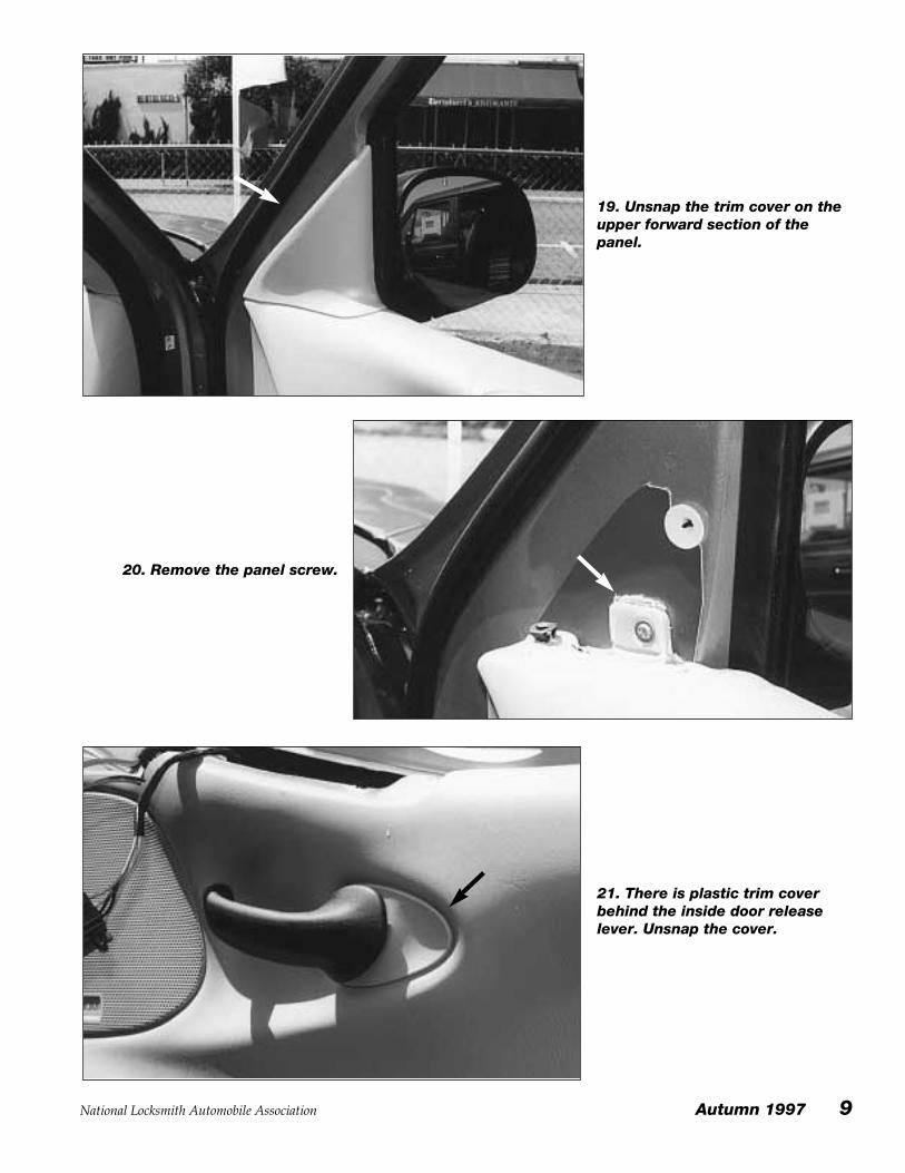
19. Unsnap the trim cover on theupper forward section of thepanel.
20. Remove the panel screw.
21. There is plastic trim coverbehind the inside door releaselever. Unsnap the cover.
10 Autumn 1997 National Locksmith Automobile Association
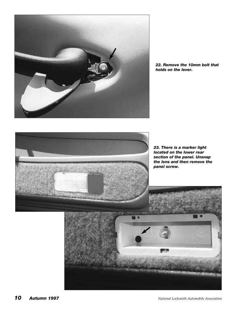
22. Remove the 10mm bolt thatholds on the lever.
23. There is a marker lightlocated on the lower rearsection of the panel. Unsnapthe lens and then remove thepanel screw.
National Locksmith Automobile Association Autumn 1997 11
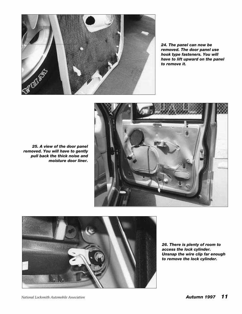
24. The panel can now beremoved. The door panel usehook type fasteners. You willhave to lift upward on the panelto remove it.
25. A view of the door panelremoved. You will have to gently
pull back the thick noise andmoisture door liner.
26. There is plenty of room toaccess the lock cylinder.Unsnap the wire clip far enoughto remove the lock cylinder.
12 Autumn 1997 National Locksmith Automobile Association
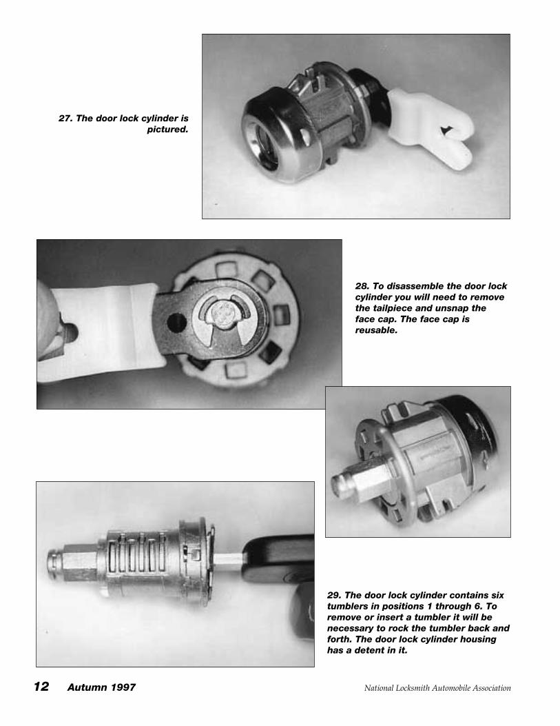
27. The door lock cylinder ispictured.
28. To disassemble the door lockcylinder you will need to removethe tailpiece and unsnap theface cap. The face cap isreusable.
29. The door lock cylinder contains sixtumblers in positions 1 through 6. Toremove or insert a tumbler it will benecessary to rock the tumbler back andforth. The door lock cylinder housinghas a detent in it.
National Locksmith Automobile Association Autumn 1997 13
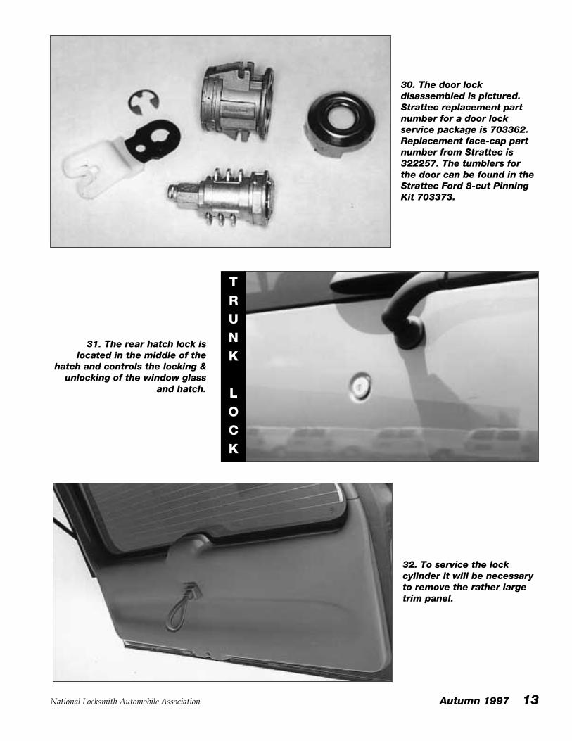
30. The door lockdisassembled is pictured.Strattec replacement partnumber for a door lockservice package is 703362.Replacement face-cap partnumber from Strattec is322257. The tumblers forthe door can be found in theStrattec Ford 8-cut PinningKit 703373.
31. The rear hatch lock islocated in the middle of the
hatch and controls the locking &unlocking of the window glass
and hatch.
TRUNK
LOCK
32. To service the lockcylinder it will be necessaryto remove the rather largetrim panel.
14 Autumn 1997 National Locksmith Automobile Association
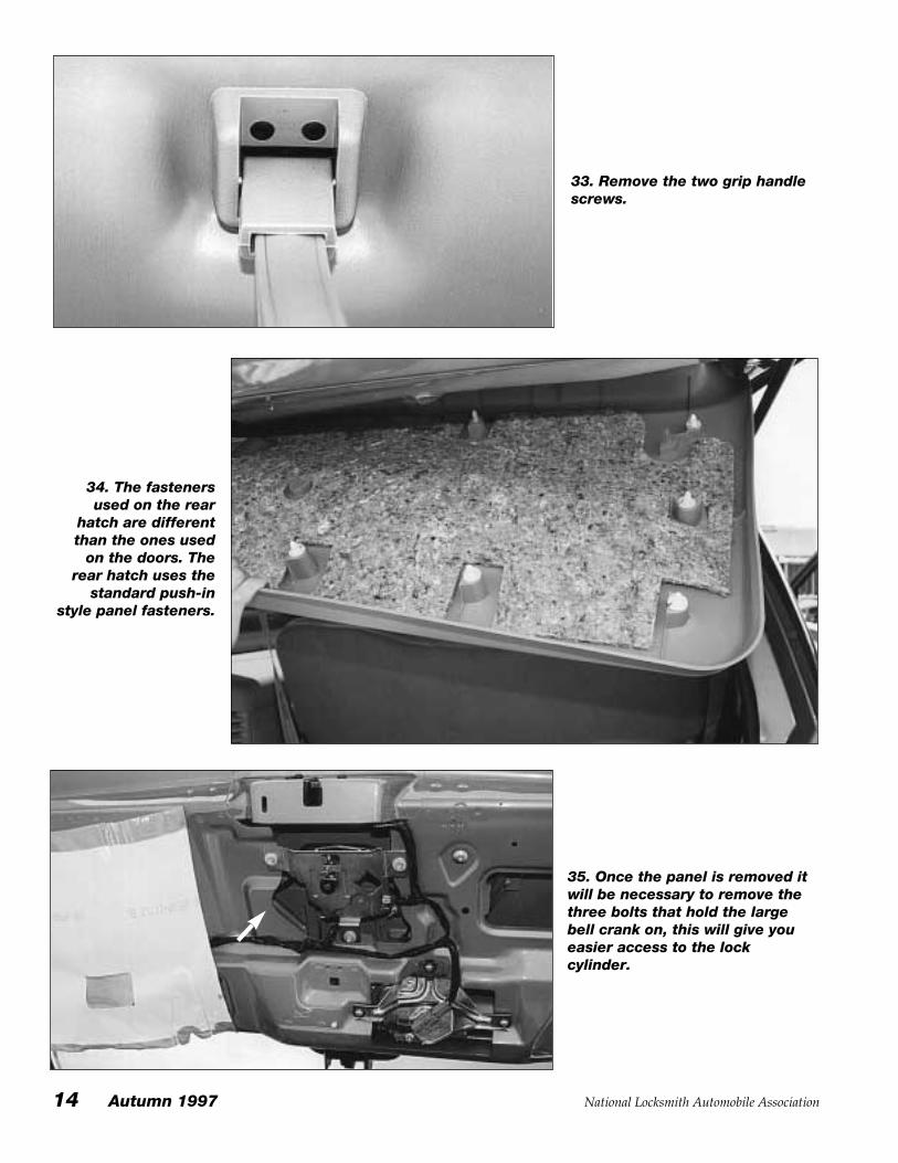
33. Remove the two grip handlescrews.
34. The fastenersused on the rear
hatch are differentthan the ones used
on the doors. Therear hatch uses the
standard push-instyle panel fasteners.
35. Once the panel is removed itwill be necessary to remove thethree bolts that hold the largebell crank on, this will give youeasier access to the lockcylinder.
National Locksmith Automobile Association Autumn 1997 15
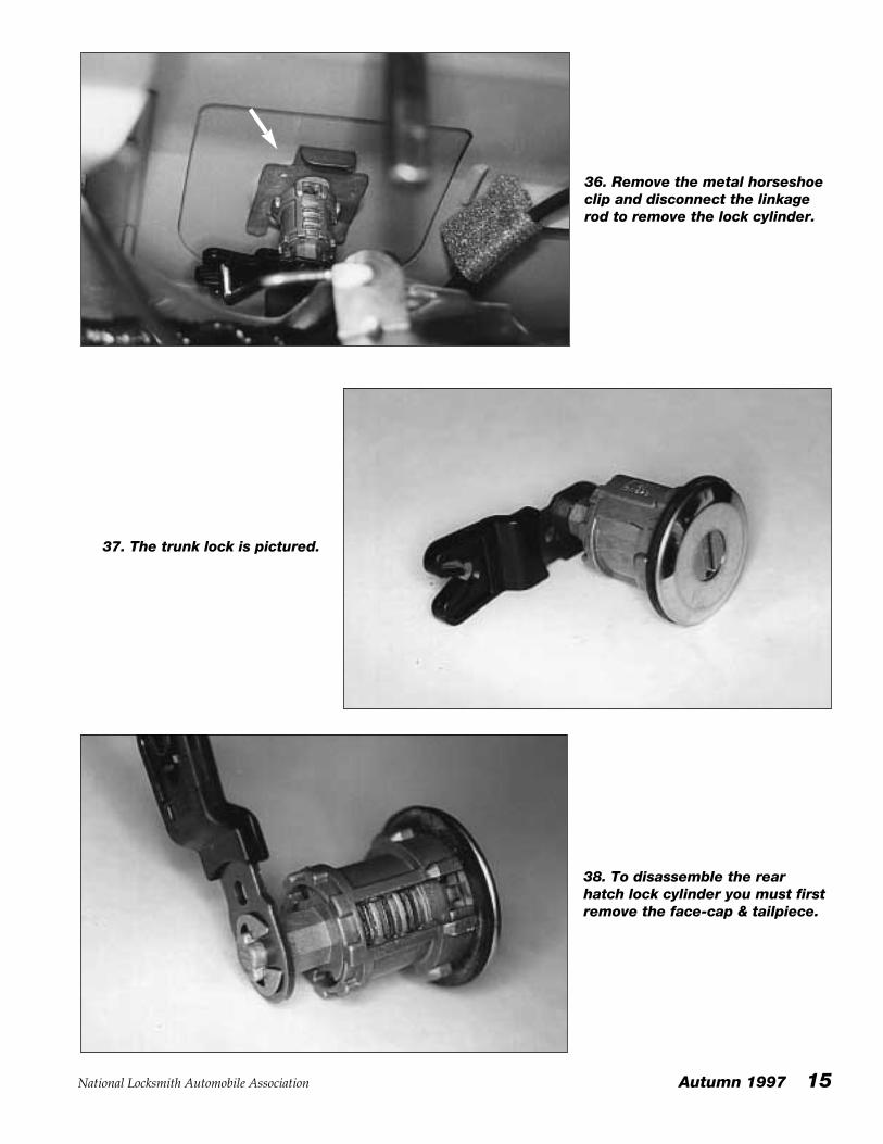
36. Remove the metal horseshoeclip and disconnect the linkagerod to remove the lock cylinder.
37. The trunk lock is pictured.
38. To disassemble the rearhatch lock cylinder you must firstremove the face-cap & tailpiece.
16 Autumn 1997 National Locksmith Automobile Association
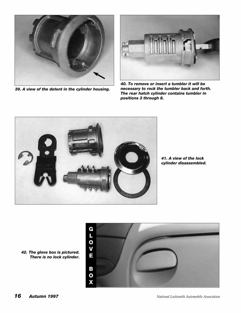
41. A view of the lockcylinder disassembled.
42. The glove box is pictured.There is no lock cylinder.
GLOVE
BOX
39. A view of the detent in the cylinder housing.40. To remove or insert a tumbler it will benecessary to rock the tumbler back and forth.The rear hatch cylinder contains tumbler inpositions 3 through 8.
National Locksmith Automobile Association Autumn 1997 17
Making First Key:There are two steps, first you
must make a mechanical key andthen program in the new PATS(Transponder) code.
Step One / Mechanical Key:Method #1 — Use EEZ-Reader in
door lock, to determine cuts inpositions 1 through 6, and thenprogression the two remainingcuts in the ignition, for positions 7& 8. Or, impression/progressionthe remaining two cuts in the trunklock. (The EEZ-Reader is sold byH.E. Mitchell Co.)
Method #2 — Remove the doorcylinder and disassemble todecode the tumblers. Progressionthe two remaining cuts in theignition, for positions 7 & 8. Or,impression/progression theremaining two cuts in the rearhatch lock.
Step Two / Transponder: Programming Replacement
Keys. (No other working key forcar is available.)
1) Put the newly cut key into thekeyway and turn it to the ON(RUN) position. A theft indicatorlight on the dashboard will flashfor 15 minutes.
2) Within 5 minutes after theindicator light stops flashing, turnthe ignition to OFF, then return tothe ON (RUN) position. The
indicator light again will flash for15 minutes.
3) Again, within 5 minutes afterthe indicator light stops flashing,turn the ignition to OFF, thenreturn to the ON (RUN) position.The indicator light again will flashfor 15 minutes.
When the light stops flashing forthe third time, the new key isprogrammed into the computerand will start the car. Allpreviously stored codes will beerased. To stop the process at anytime, simply remove the key anduse an existing key to start the car.
To Create Just A Spare Key:As many as 16 keys, each with its
own individual electronic code,can be programmed into thecomputer for a vehicle equippedwith PATS. The system will ignoreattempts to enter a 17th code. If akey already programmed into thecomputer is available,programming another key onlytakes seconds.
1) Place an already programmedkey in the keyway. Cycle theignition from OFF to ON(RUN) toOFF.
2) Within 15 seconds, insert thenew, properly cut PATS key in theignition. Turn the key to ON(RUN)or START. The theft indicator lightwill go on for two seconds, after
which the key will start the vehicle.
3) Repeat the second step foreach new key to be programmed.
4) If the light flashes for 15minutes, too much time elapsedbetween cycling of the alreadyprogrammed key and the new key.If this happens, simply start over.If the light flashes for 1 minute, thenew key is defective or is not aPATS key. Start again with adifferent key. To stop the processat any time, simply remove the keyand use the pre-existing key tostart the car.
5) To remove any key code fromthe system, erase all stored codesusing the programming mode andre-enter the desired spare keys.
Code Series: FORD 8-Cut,0001X-1706XKey Blank: Ilco: H72-PTSilca: FO38RT3Curtis: H72-PTM.A.C.S.: 2Framon: First cut: .405
Use spacing clip, align tip of keywith left side of vise. Lay clipFLAT on left side of vise and slidekey in from right.
Cut to Cut: .092
Depths: 1=.354, 2=.329, 3=.304,4=.279, 5=.254
NOTES:
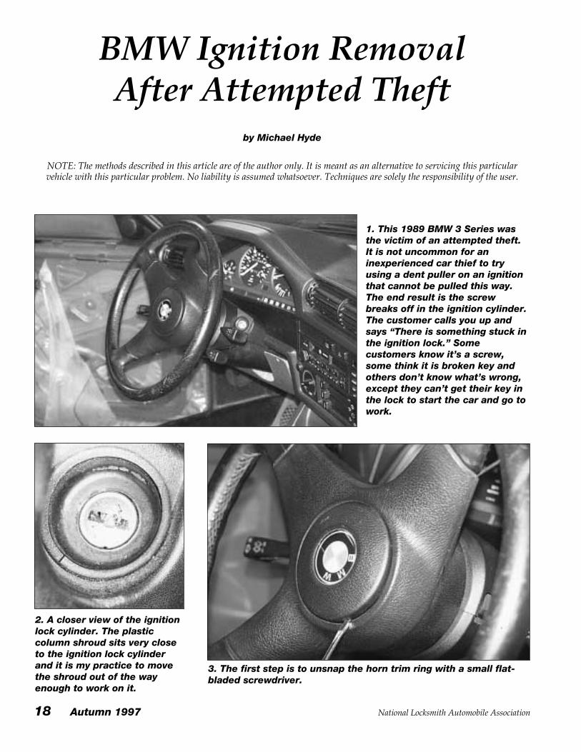
BMW Ignition Removal After Attempted Theft
by Michael Hyde
NOTE: The methods described in this article are of the author only. It is meant as an alternative to servicing this particularvehicle with this particular problem. No liability is assumed whatsoever. Techniques are solely the responsibility of the user.
1. This 1989 BMW 3 Series wasthe victim of an attempted theft.It is not uncommon for aninexperienced car thief to tryusing a dent puller on an ignitionthat cannot be pulled this way.The end result is the screwbreaks off in the ignition cylinder.The customer calls you up andsays “There is something stuck inthe ignition lock.” Somecustomers know it’s a screw,some think it is broken key andothers don’t know what’s wrong,except they can’t get their key inthe lock to start the car and go towork.
2. A closer view of the ignitionlock cylinder. The plasticcolumn shroud sits very closeto the ignition lock cylinderand it is my practice to movethe shroud out of the wayenough to work on it.
3. The first step is to unsnap the horn trim ring with a small flat-bladed screwdriver.
18 Autumn 1997 National Locksmith Automobile Association
National Locksmith Automobile Association Autumn 1997 19
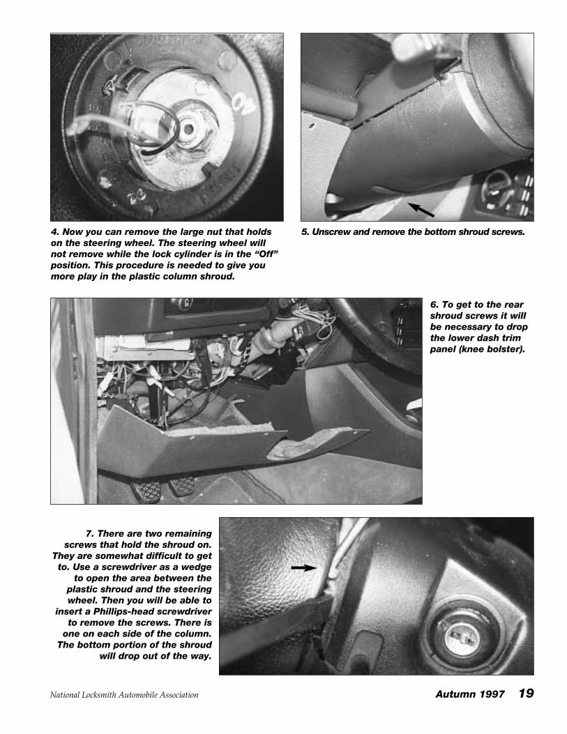
4. Now you can remove the large nut that holdson the steering wheel. The steering wheel willnot remove while the lock cylinder is in the “Off”position. This procedure is needed to give youmore play in the plastic column shroud.
5. Unscrew and remove the bottom shroud screws.
6. To get to the rearshroud screws it willbe necessary to dropthe lower dash trimpanel (knee bolster).
7. There are two remainingscrews that hold the shroud on.
They are somewhat difficult to getto. Use a screwdriver as a wedge
to open the area between theplastic shroud and the steeringwheel. Then you will be able to
insert a Phillips-head screwdriverto remove the screws. There is
one on each side of the column.The bottom portion of the shroud
will drop out of the way.
20 Autumn 1997 National Locksmith Automobile Association
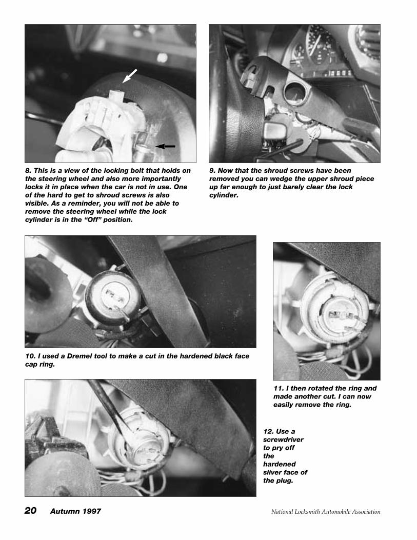
8. This is a view of the locking bolt that holds onthe steering wheel and also more importantlylocks it in place when the car is not in use. Oneof the hard to get to shroud screws is alsovisible. As a reminder, you will not be able toremove the steering wheel while the lockcylinder is in the “Off” position.
9. Now that the shroud screws have beenremoved you can wedge the upper shroud pieceup far enough to just barely clear the lockcylinder.
10. I used a Dremel tool to make a cut in the hardened black facecap ring.
11. I then rotated the ring andmade another cut. I can noweasily remove the ring.
12. Use ascrewdriverto pry offthehardenedsliver face ofthe plug.
National Locksmith Automobile Association Autumn 1997 21
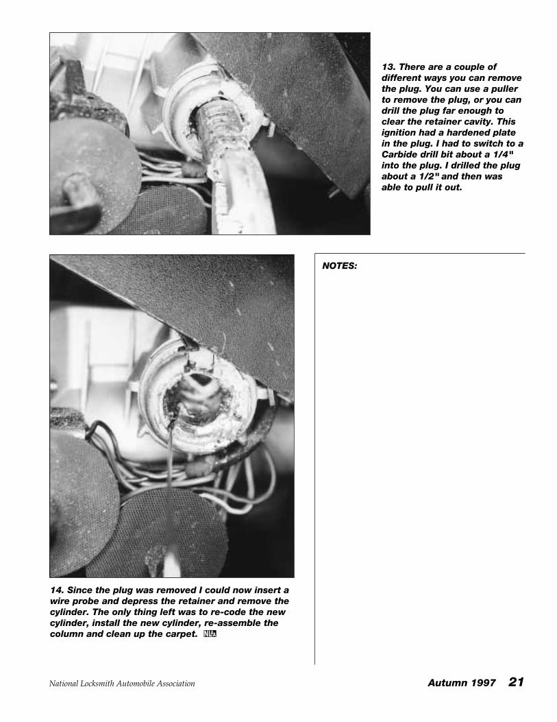
13. There are a couple ofdifferent ways you can removethe plug. You can use a pullerto remove the plug, or you candrill the plug far enough toclear the retainer cavity. Thisignition had a hardened platein the plug. I had to switch to aCarbide drill bit about a 1/4"into the plug. I drilled the plugabout a 1/2" and then wasable to pull it out.
14. Since the plug was removed I could now insert awire probe and depress the retainer and remove thecylinder. The only thing left was to re-code the newcylinder, install the new cylinder, re-assemble thecolumn and clean up the carpet.
NOTES:
22 Autumn 1997 National Locksmith Automobile Association
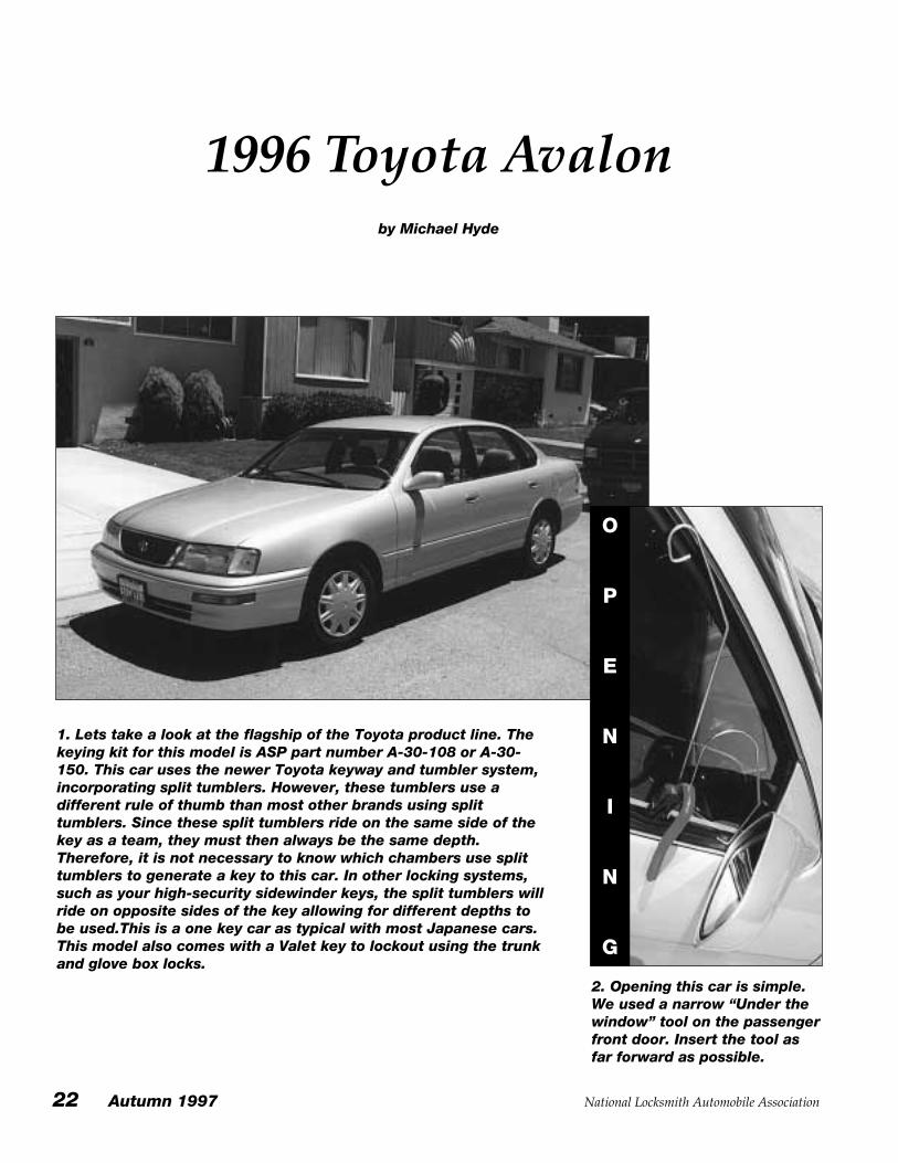
1. Lets take a look at the flagship of the Toyota product line. Thekeying kit for this model is ASP part number A-30-108 or A-30-150. This car uses the newer Toyota keyway and tumbler system,incorporating split tumblers. However, these tumblers use adifferent rule of thumb than most other brands using splittumblers. Since these split tumblers ride on the same side of thekey as a team, they must then always be the same depth.Therefore, it is not necessary to know which chambers use splittumblers to generate a key to this car. In other locking systems,such as your high-security sidewinder keys, the split tumblers willride on opposite sides of the key allowing for different depths tobe used.This is a one key car as typical with most Japanese cars.This model also comes with a Valet key to lockout using the trunkand glove box locks.
1996 Toyota Avalonby Michael Hyde
2. Opening this car is simple.We used a narrow “Under thewindow” tool on the passengerfront door. Insert the tool asfar forward as possible.
O
P
E
N
I
N
G
National Locksmith Automobile Association Autumn 1997 23
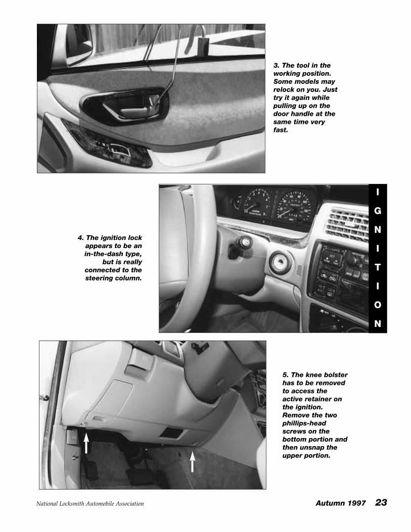
3. The tool in theworking position.Some models mayrelock on you. Justtry it again whilepulling up on thedoor handle at thesame time veryfast.
I
G
N
I
T
I
O
N
4. The ignition lockappears to be anin-the-dash type,
but is reallyconnected to thesteering column.
5. The knee bolsterhas to be removedto access theactive retainer onthe ignition.Remove the twophillips-headscrews on thebottom portion andthen unsnap theupper portion.
24 Autumn 1997 National Locksmith Automobile Association
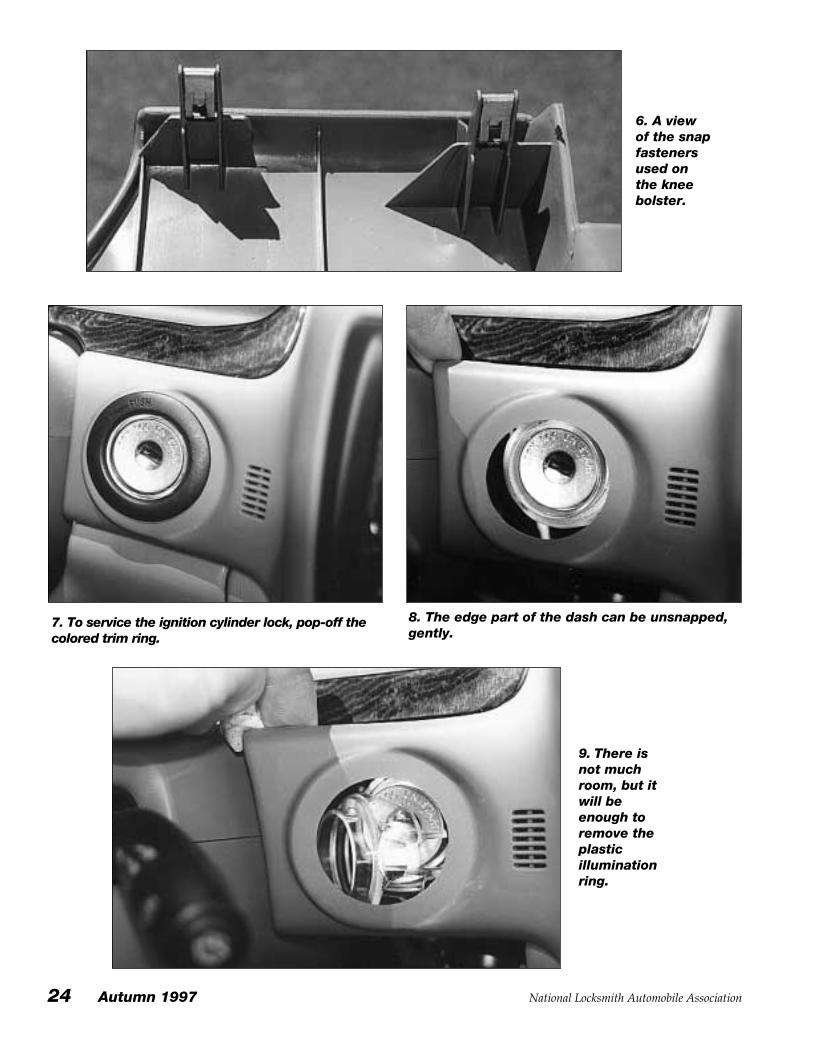
6. A viewof the snapfastenersused onthe kneebolster.
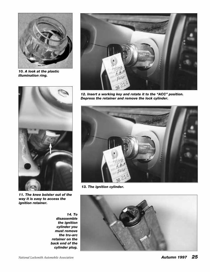
7. To service the ignition cylinder lock, pop-off thecolored trim ring.
8. The edge part of the dash can be unsnapped,gently.
9. There isnot muchroom, but itwill beenough toremove theplasticilluminationring.
National Locksmith Automobile Association Autumn 1997 25
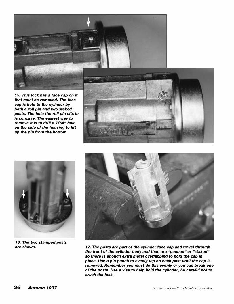
10. A look at the plasticillumination ring.
11. The knee bolster out of theway it is easy to access theignition retainer.
12. Insert a working key and rotate it to the “ACC” position.Depress the retainer and remove the lock cylinder.
13. The ignition cylinder.
14. Todisassemblethe ignition
cylinder youmust remove
the tru-arcretainer on theback end of the
cylinder plug.
26 Autumn 1997 National Locksmith Automobile Association
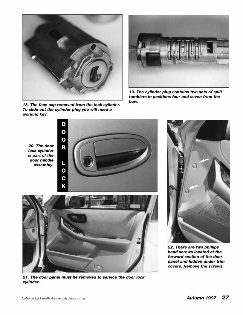
15. This lock has a face cap on itthat must be removed. The facecap is held to the cylinder byboth a roll pin and two stakedposts. The hole the roll pin sits inis concave. The easiest way toremove it is to drill a 7/64” holeon the side of the housing to liftup the pin from the bottom.
16. The two stamped postsare shown. 17. The posts are part of the cylinder face cap and travel through
the front of the cylinder body and then are “peened” or “staked”so there is enough extra metal overlapping to hold the cap inplace. Use a pin punch to evenly tap on each post until the cap isremoved. Remember you must do this evenly or you can break oneof the posts. Use a vise to help hold the cylinder, be careful not tocrush the lock.
National Locksmith Automobile Association Autumn 1997 27
18. The face cap removed from the lock cylinder.To slide out the cylinder plug you will need aworking key.
19. The cylinder plug contains two sets of splittumblers in positions four and seven from thebow.
20. The doorlock cylinderis part of thedoor handle
assembly.
DOOR
LOCK
21. The door panel must be removed to service the door lockcylinder.
22. There are two phillipshead screws located at theforward section of the doorpanel and hidden under trimcovers. Remove the screws.
28 Autumn 1997 National Locksmith Automobile Association
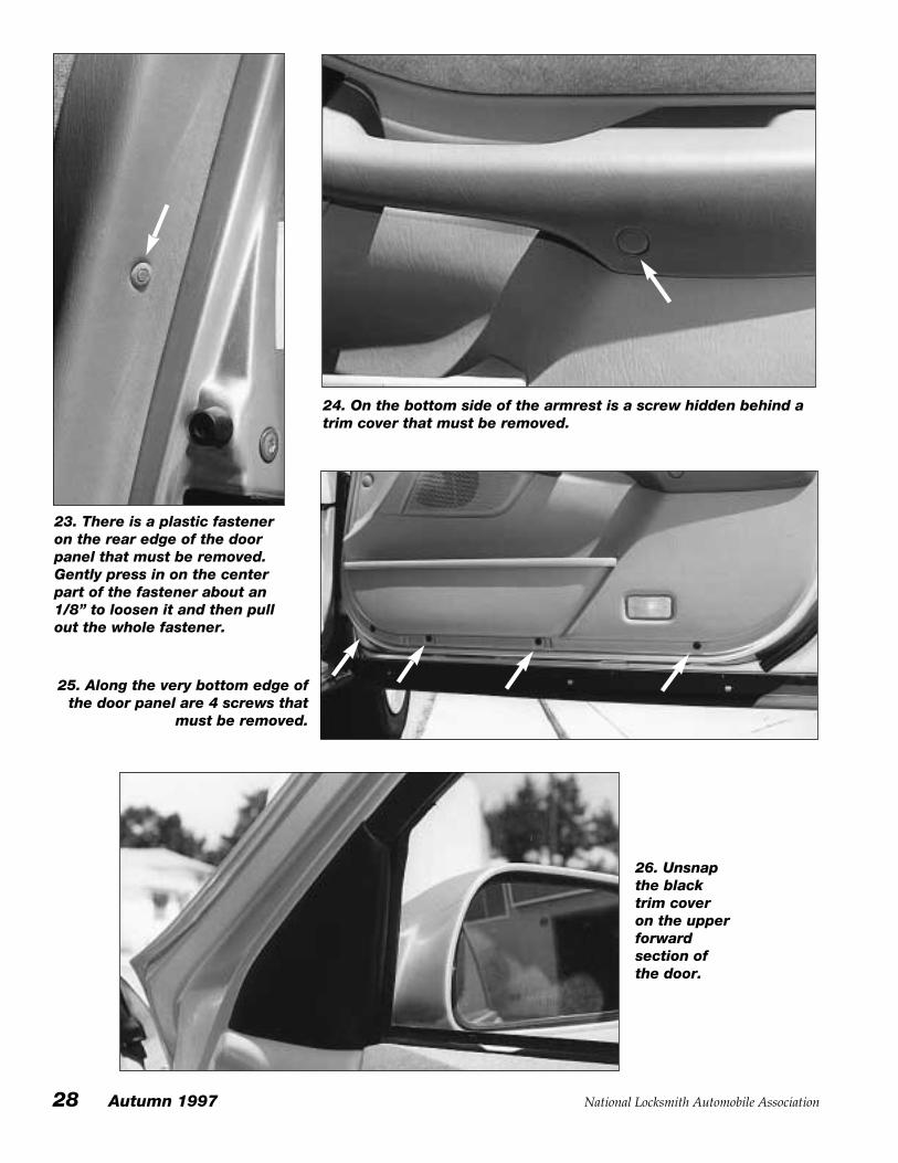
23. There is a plastic fasteneron the rear edge of the doorpanel that must be removed.Gently press in on the centerpart of the fastener about an1/8” to loosen it and then pullout the whole fastener.
24. On the bottom side of the armrest is a screw hidden behind atrim cover that must be removed.
25. Along the very bottom edge ofthe door panel are 4 screws that
must be removed.
26. Unsnapthe blacktrim coveron the upperforwardsection ofthe door.
National Locksmith Automobile Association Autumn 1997 29
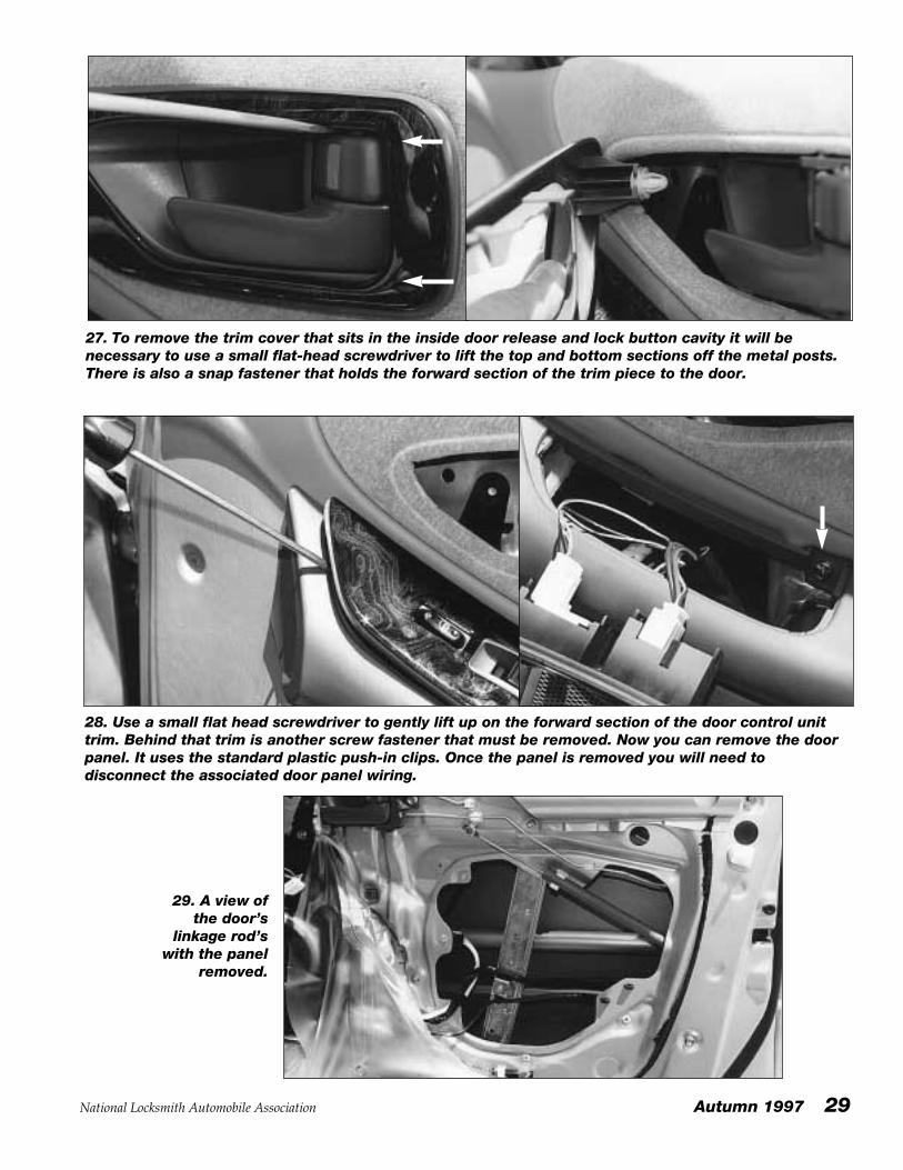
27. To remove the trim cover that sits in the inside door release and lock button cavity it will benecessary to use a small flat-head screwdriver to lift the top and bottom sections off the metal posts.There is also a snap fastener that holds the forward section of the trim piece to the door.
28. Use a small flat head screwdriver to gently lift up on the forward section of the door control unittrim. Behind that trim is another screw fastener that must be removed. Now you can remove the doorpanel. It uses the standard plastic push-in clips. Once the panel is removed you will need todisconnect the associated door panel wiring.
29. A view ofthe door’s
linkage rod’swith the panel
removed.
30 Autumn 1997 National Locksmith Automobile Association
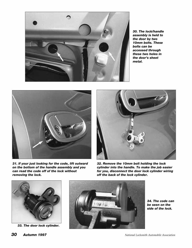
30. The lock/handleassembly is held tothe door by two10mm bolts. Thesebolts can beaccessed throughthese two holes inthe door’s sheetmetal.
31. If your just looking for the code, lift outwardon the bottom of the handle assembly and youcan read the code off of the lock withoutremoving the lock.
32. Remove the 10mm bolt holding the lockcylinder into the handle. To make the job easierfor you, disconnect the door lock cylinder wiringoff the back of the lock cylinder.
33. The door lock cylinder.
34. The code canbe seen on theside of the lock.
National Locksmith Automobile Association Autumn 1997 31
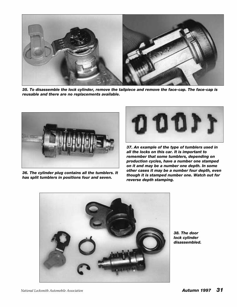
35. To disassemble the lock cylinder, remove the tailpiece and remove the face-cap. The face-cap isreusable and there are no replacements available.
36. The cylinder plug contains all the tumblers. Ithas split tumblers in positions four and seven.
37. An example of the type of tumblers used inall the locks on this car. It is important toremember that some tumblers, depending onproduction cycles, have a number one stampedon it and may be a number one depth. In someother cases it may be a number four depth, eventhough it is stamped number one. Watch out forreverse depth stamping.
38. The doorlock cylinderdisassembled.
32 Autumn 1997 National Locksmith Automobile Association
T
R
U
N
K
L
O
C
K
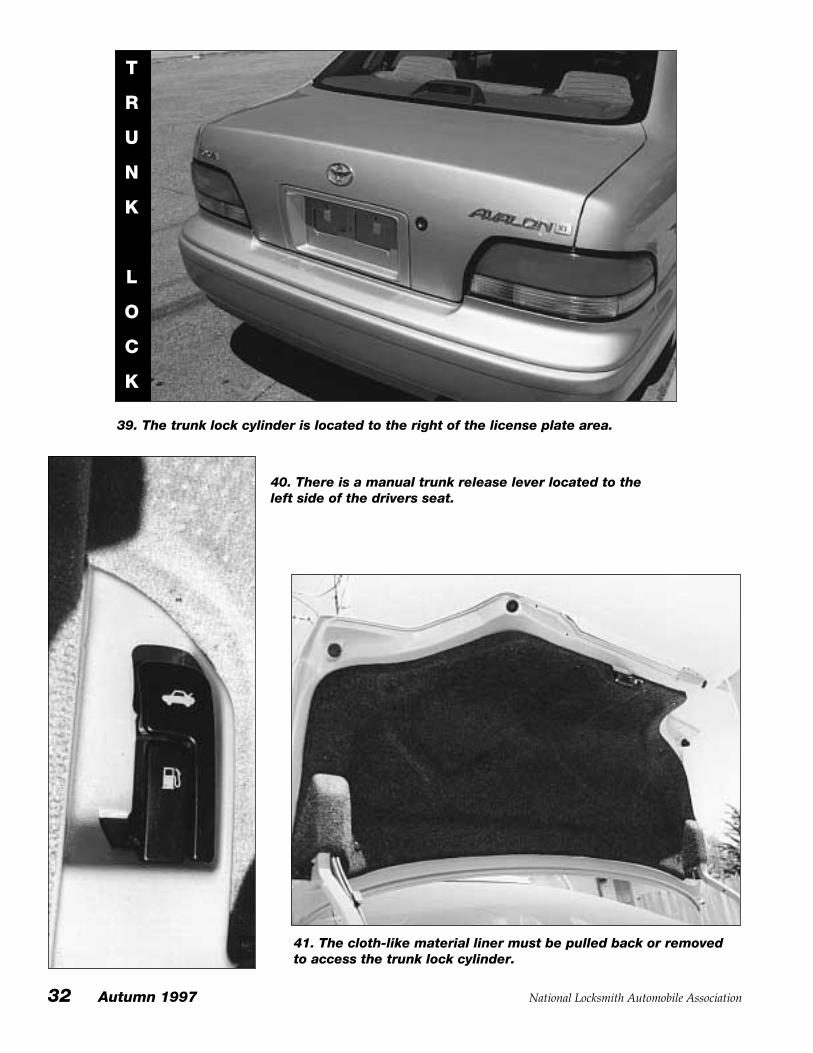
39. The trunk lock cylinder is located to the right of the license plate area.
40. There is a manual trunk release lever located to theleft side of the drivers seat.
41. The cloth-like material liner must be pulled back or removedto access the trunk lock cylinder.
National Locksmith Automobile Association Autumn 1997 33
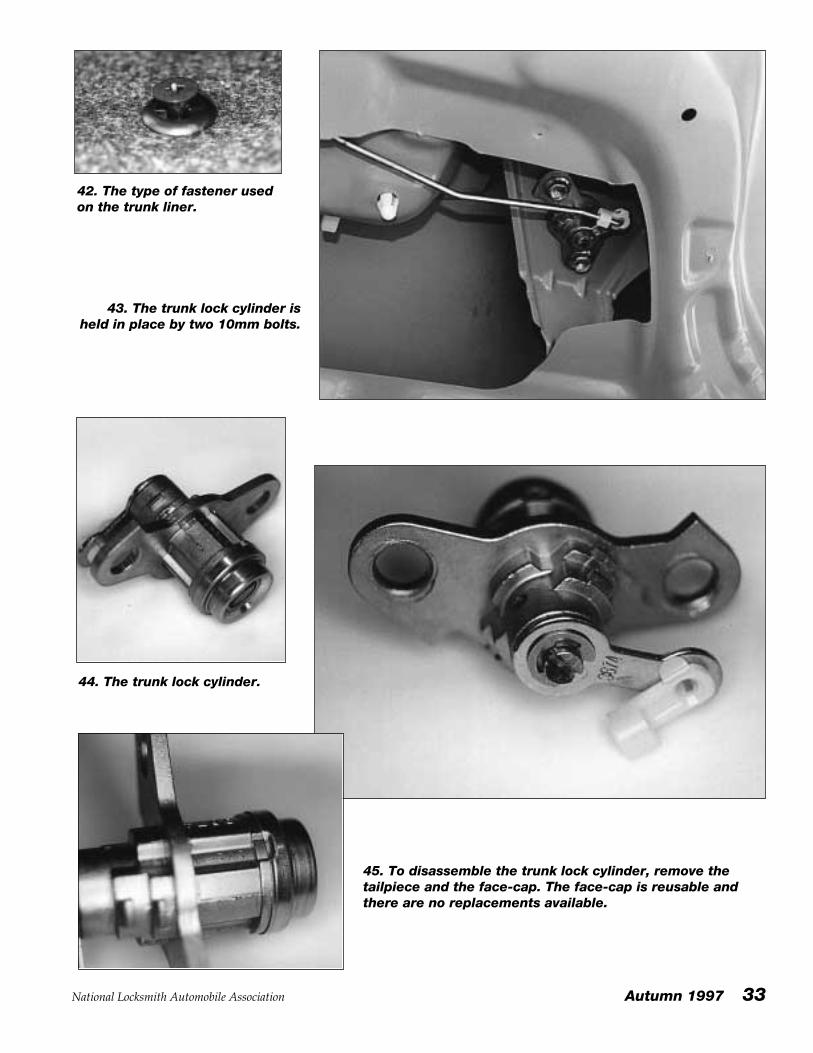
42. The type of fastener usedon the trunk liner.
43. The trunk lock cylinder isheld in place by two 10mm bolts.
44. The trunk lock cylinder.
45. To disassemble the trunk lock cylinder, remove thetailpiece and the face-cap. The face-cap is reusable andthere are no replacements available.
34 Autumn 1997 National Locksmith Automobile Association
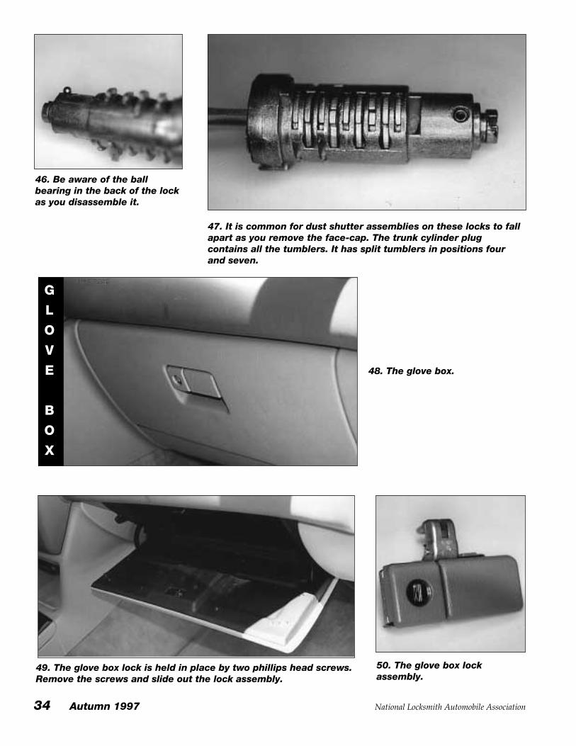
49. The glove box lock is held in place by two phillips head screws.Remove the screws and slide out the lock assembly.
50. The glove box lockassembly.
46. Be aware of the ballbearing in the back of the lockas you disassemble it.
47. It is common for dust shutter assemblies on these locks to fallapart as you remove the face-cap. The trunk cylinder plugcontains all the tumblers. It has split tumblers in positions fourand seven.
48. The glove box.
G
L
O
V
E
B
O
X
National Locksmith Automobile Association Autumn 1997 35
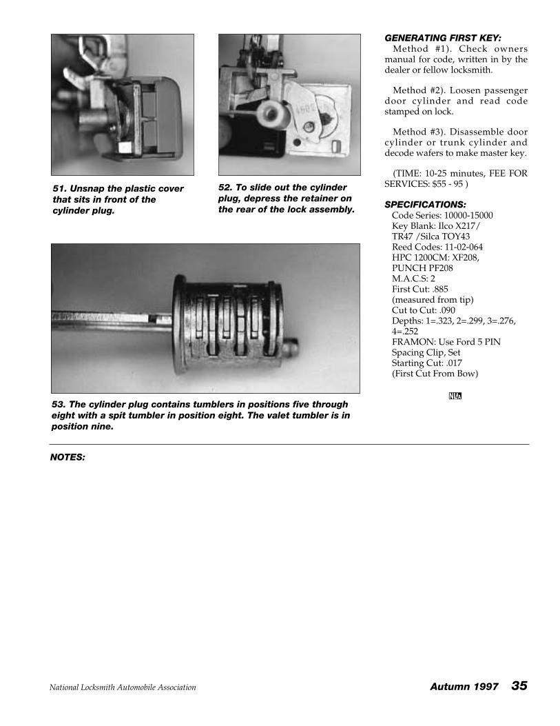
51. Unsnap the plastic coverthat sits in front of thecylinder plug.
52. To slide out the cylinderplug, depress the retainer onthe rear of the lock assembly.
53. The cylinder plug contains tumblers in positions five througheight with a spit tumbler in position eight. The valet tumbler is inposition nine.
GENERATING FIRST KEY:Method #1). Check owners
manual for code, written in by thedealer or fellow locksmith.
Method #2). Loosen passengerdoor cylinder and read codestamped on lock.
Method #3). Disassemble doorcylinder or trunk cylinder anddecode wafers to make master key.
(TIME: 10-25 minutes, FEE FORSERVICES: $55 - 95 )
SPECIFICATIONS:Code Series: 10000-15000Key Blank: Ilco X217/TR47 /Silca TOY43Reed Codes: 11-02-064HPC 1200CM: XF208, PUNCH PF208M.A.C.S: 2First Cut: .885(measured from tip)Cut to Cut: .090Depths: 1=.323, 2=.299, 3=.276,4=.252FRAMON: Use Ford 5 PINSpacing Clip, SetStarting Cut: .017 (First Cut From Bow)
NOTES:
36 Autumn 1997 National Locksmith Automobile Association
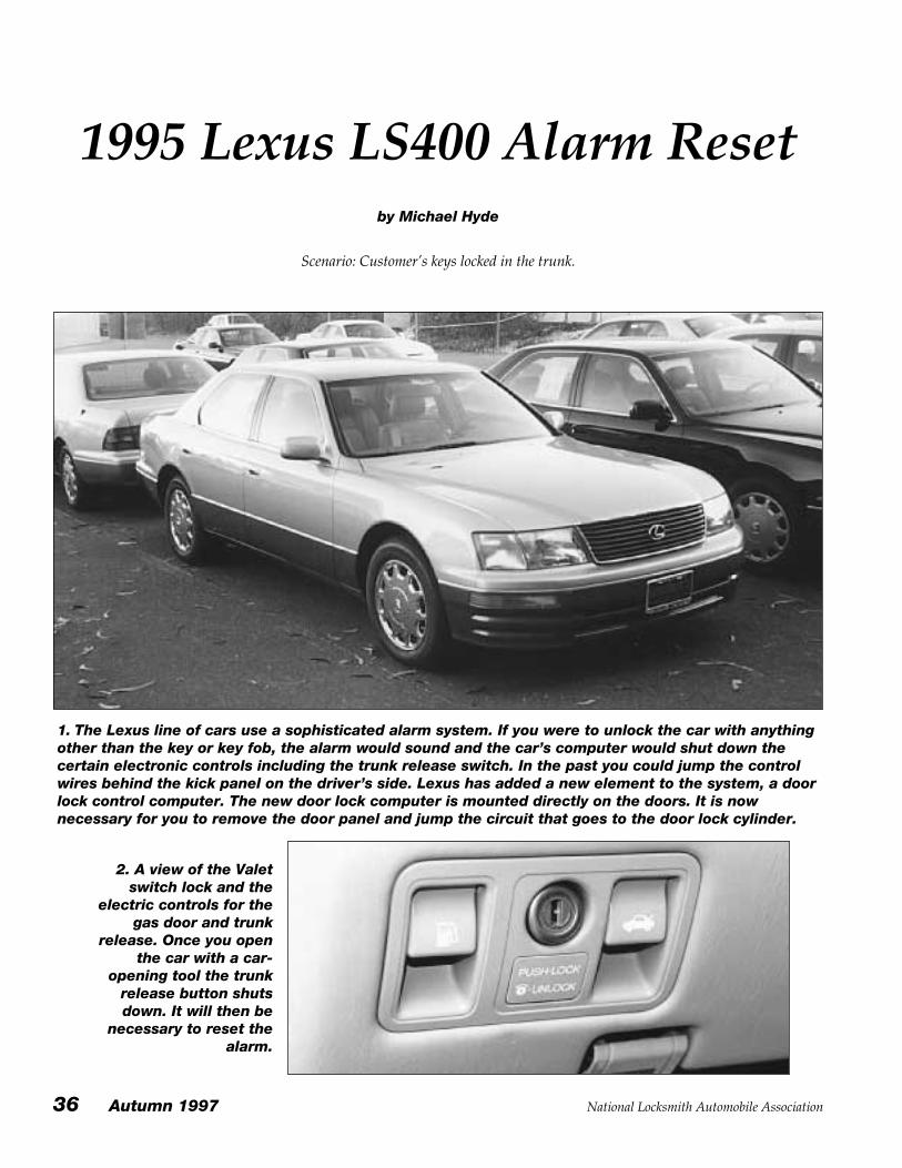
1995 Lexus LS400 Alarm Resetby Michael Hyde
Scenario: Customer’s keys locked in the trunk.
1. The Lexus line of cars use a sophisticated alarm system. If you were to unlock the car with anythingother than the key or key fob, the alarm would sound and the car’s computer would shut down thecertain electronic controls including the trunk release switch. In the past you could jump the controlwires behind the kick panel on the driver’s side. Lexus has added a new element to the system, a doorlock control computer. The new door lock computer is mounted directly on the doors. It is nownecessary for you to remove the door panel and jump the circuit that goes to the door lock cylinder.
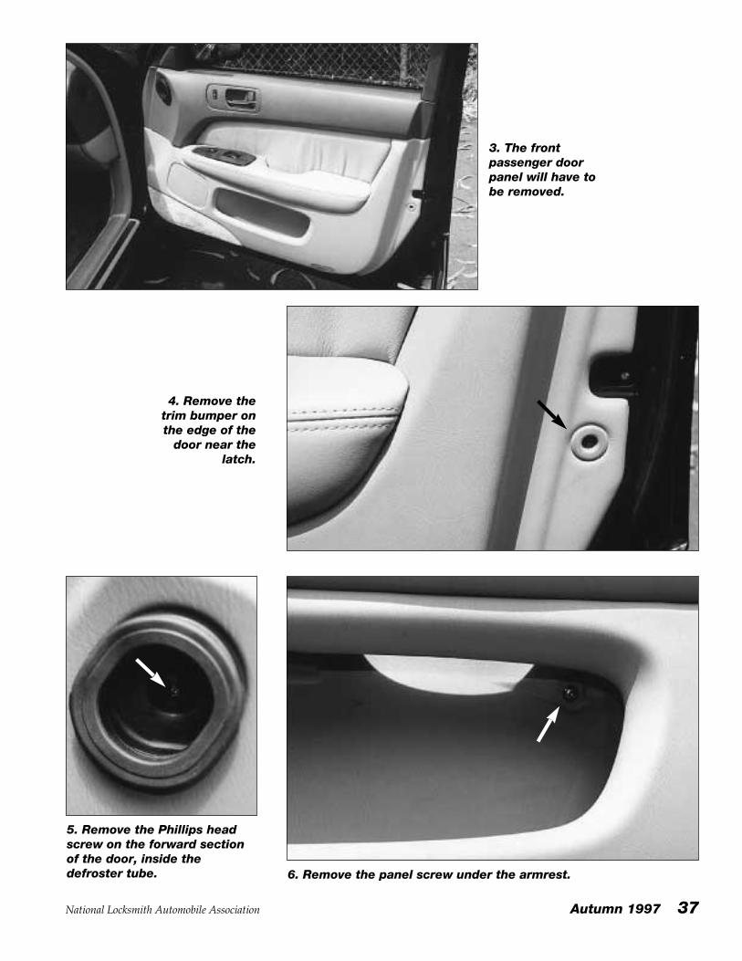
2. A view of the Valetswitch lock and the
electric controls for thegas door and trunk
release. Once you openthe car with a car-
opening tool the trunkrelease button shutsdown. It will then be
necessary to reset thealarm.
National Locksmith Automobile Association Autumn 1997 37
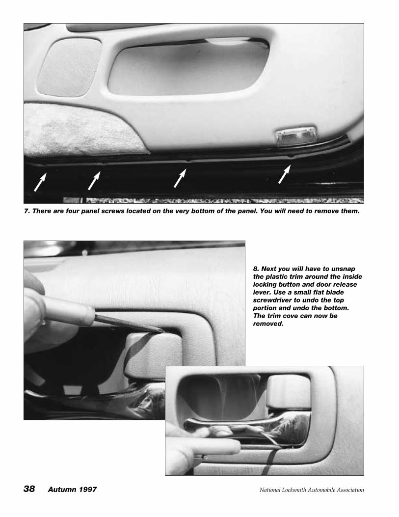
3. The frontpassenger doorpanel will have tobe removed.
4. Remove thetrim bumper onthe edge of the
door near thelatch.
5. Remove the Phillips headscrew on the forward sectionof the door, inside thedefroster tube. 6. Remove the panel screw under the armrest.
38 Autumn 1997 National Locksmith Automobile Association
7. There are four panel screws located on the very bottom of the panel. You will need to remove them.
8. Next you will have to unsnapthe plastic trim around the insidelocking button and door releaselever. Use a small flat bladescrewdriver to undo the topportion and undo the bottom.The trim cove can now beremoved.
National Locksmith Automobile Association Autumn 1997 39
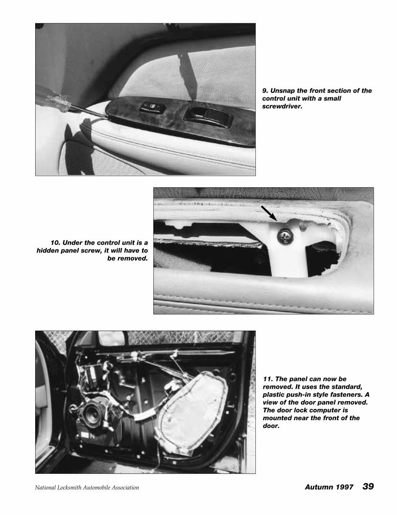
9. Unsnap the front section of thecontrol unit with a smallscrewdriver.
10. Under the control unit is ahidden panel screw, it will have to
be removed.
11. The panel can now beremoved. It uses the standard,plastic push-in style fasteners. Aview of the door panel removed.The door lock computer ismounted near the front of thedoor.
40 Autumn 1997 National Locksmith Automobile Association
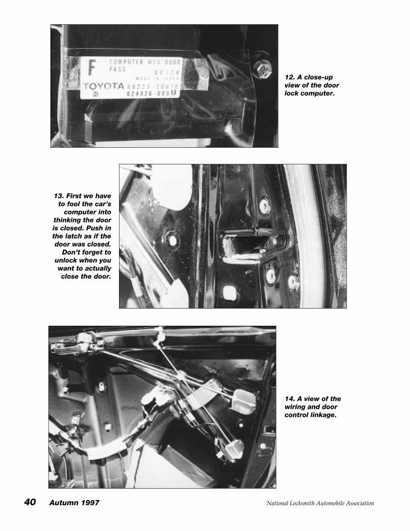
12. A close-upview of the doorlock computer.
13. First we haveto fool the car’s
computer intothinking the dooris closed. Push inthe latch as if thedoor was closed.
Don’t forget tounlock when youwant to actuallyclose the door.
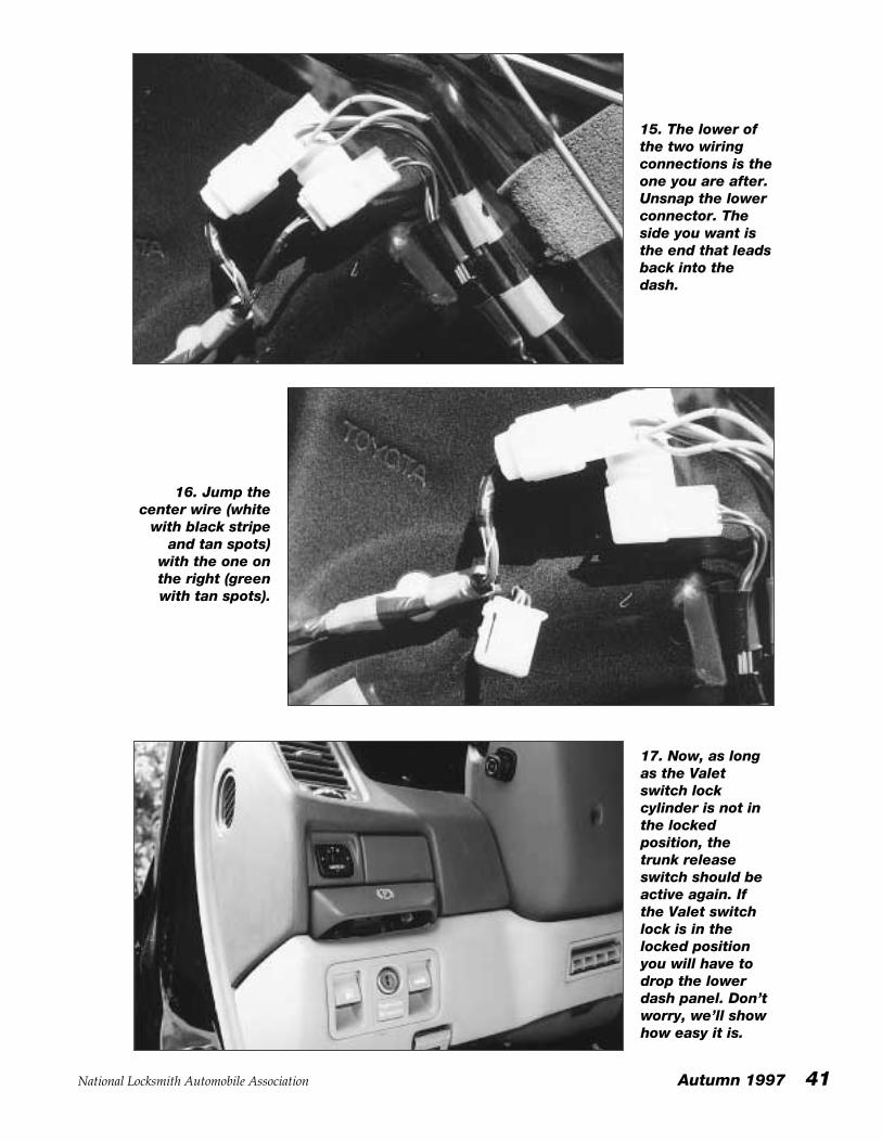
14. A view of thewiring and doorcontrol linkage.
National Locksmith Automobile Association Autumn 1997 41
15. The lower ofthe two wiringconnections is theone you are after.Unsnap the lowerconnector. Theside you want isthe end that leadsback into thedash.
16. Jump thecenter wire (white
with black stripeand tan spots)
with the one onthe right (greenwith tan spots).
17. Now, as longas the Valetswitch lockcylinder is not inthe lockedposition, thetrunk releaseswitch should beactive again. Ifthe Valet switchlock is in thelocked positionyou will have todrop the lowerdash panel. Don’tworry, we’ll showhow easy it is.
42 Autumn 1997 National Locksmith Automobile Association
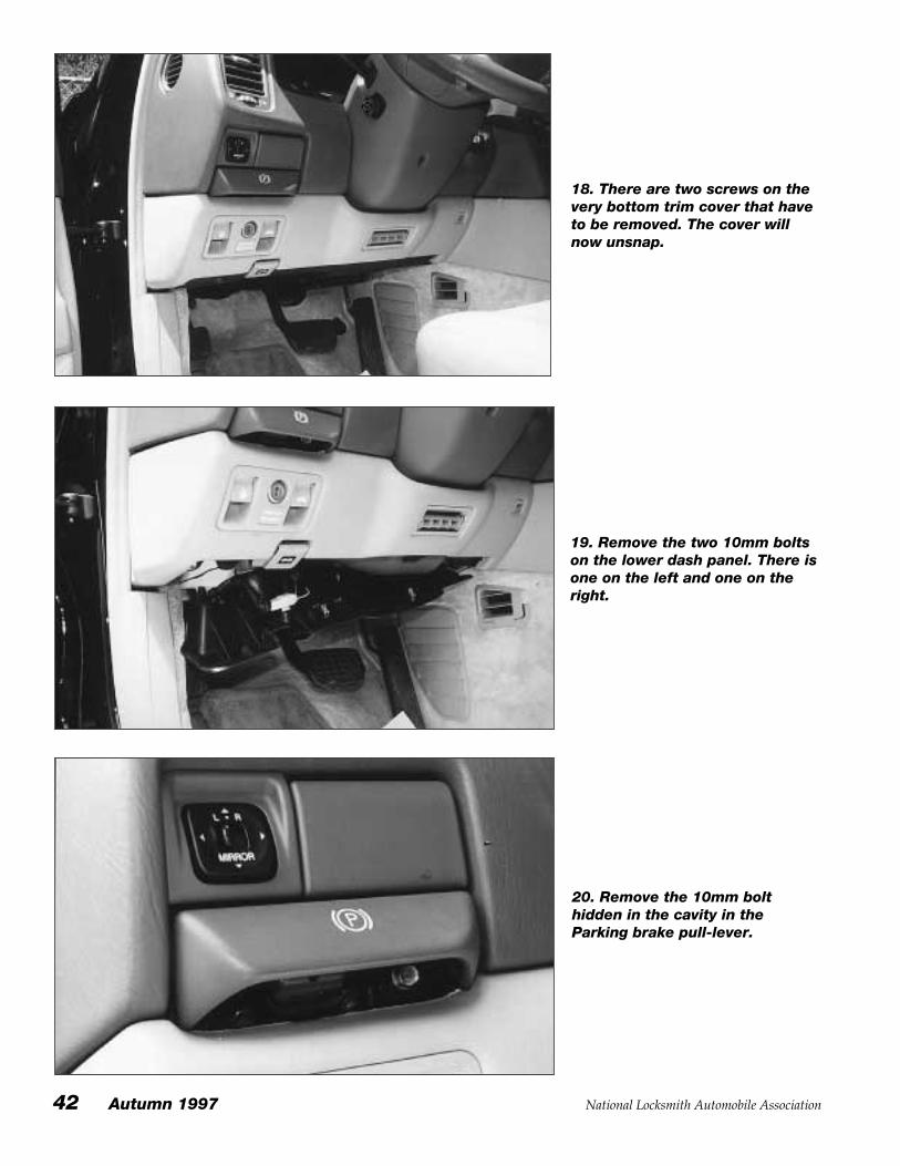
18. There are two screws on thevery bottom trim cover that haveto be removed. The cover willnow unsnap.
20. Remove the 10mm bolthidden in the cavity in theParking brake pull-lever.
19. Remove the two 10mm boltson the lower dash panel. There isone on the left and one on theright.
National Locksmith Automobile Association Autumn 1997 43
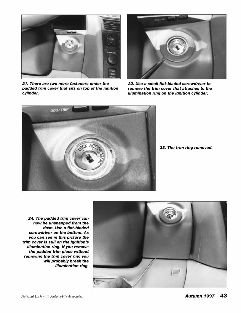
21. There are two more fasteners under thepadded trim cover that sits on top of the ignitioncylinder.
22. Use a small flat-bladed screwdriver toremove the trim cover that attaches to theillumination ring on the ignition cylinder.
23. The trim ring removed.
24. The padded trim cover cannow be unsnapped from the
dash. Use a flat-bladedscrewdriver on the bottom. Asyou can see in this picture the
trim cover is still on the ignition’sillumination ring. If you removethe padded trim piece without
removing the trim cover ring youwill probably break the
illumination ring.
44 Autumn 1997 National Locksmith Automobile Association
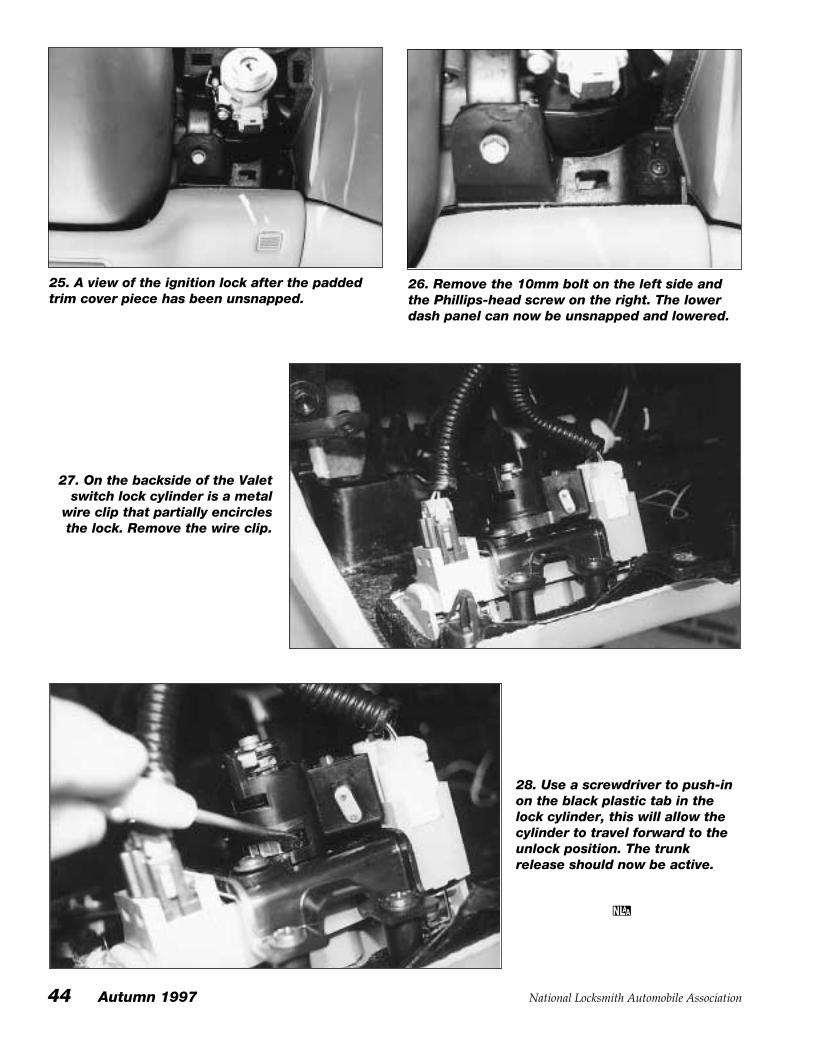
25. A view of the ignition lock after the paddedtrim cover piece has been unsnapped.
26. Remove the 10mm bolt on the left side andthe Phillips-head screw on the right. The lowerdash panel can now be unsnapped and lowered.
27. On the backside of the Valetswitch lock cylinder is a metal
wire clip that partially encirclesthe lock. Remove the wire clip.
28. Use a screwdriver to push-inon the black plastic tab in thelock cylinder, this will allow thecylinder to travel forward to theunlock position. The trunkrelease should now be active.