Embed Size (px)
Citation preview
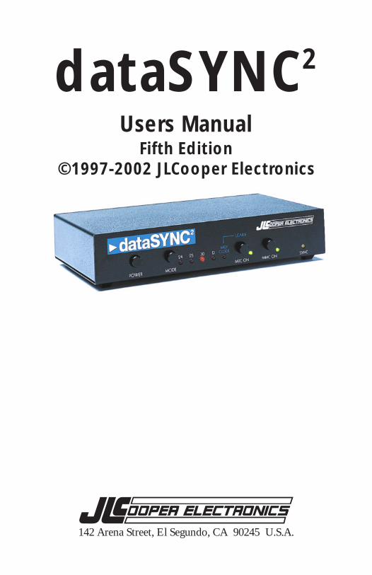
dataSYNC2
Users ManualFifth Edition
©1997-2002 JLCooper Electronics
142 Arena Street, El Segundo, CA 90245 U.S.A.
JLCooper Electronics Limited Factory WarrantyJLCooper Electronics (“JLCooper”) warrants this product to be free of defects in materialsor workmanship for a period of 12 months from the date of purchase.
This warranty is non-transferable and the benefits apply to the original owner. Proof ofpurchase in the form of an itemized sales receipt is required for warranty coverage.
To receive service under this warranty, customers in the United States should contact theJLCooper factory at (310) 322-9990 and talk to a service technician.If necessary, a Return Authorization number may be issued.
For our customers outside the United States, it is recommended that you first contact yourDealer or Distributor, since they may offer their own service or support policy.
If local support is not obtainable, please send a FAX to JLCooper’s Service Department at(310) 335-0110, with a detailed description of the service required.
Upon issuance of return authorization, the product should be properly packed and shippedto Service Department, JLCooper Electronics, 142 Arena St., El Segundo, CA 90245.
Please include the following: copy of the sales receipt, your name and address (no P.O.Boxes, please), a brief description of the problem, and any other related items discussed withthe service department and considered necessary to evaluate the product or effect a repair.The return authorization number must be clearly written on the outside of the package.
JLCooper will, without charge for parts or labor, either repair or replace the defective part(s).Shipping costs are not covered by this warranty.
JLCooper’s normal repair turn around time at the factory is approximately 15 business days,from receipt of product to shipping. Your actual turn around time will include returnshipping.
Actual turn around time will vary depending upon many factors including the repeatability ofthe customer’s reported complaint, the availability of parts required for repair, the availabilityof related products needed to evaluate the product if necessary.
Priority services are available. These should be discussed with the service technician at thetime the return authorization is issued.
This warranty provides only the benefits specified and does not cover defects or repairsneeded as result of acts beyond the control of JLCooper including but not limited to: abuse,damage by accident/negligence, modification, alteration, improper use, unauthorizedservicing, tampering, or failure to operate in accordance with the procedures outlined in theowner’s manual; nor for acts of God such as flooding, lightning, tornadoes, etc.
THE DURATION OF ANY OTHER WARRANTIES, WHETHER IMPLIED OREXPRESS, INCLUDING BUT NOT LIMITED TO THE IMPLIED WARRANTY OFMERCHANTABILITY, IS LIMITED TO THE DURATION OF THE EXPRESSWARRANTY HEREIN. JLCOOPER HEREBY EXCLUDES INCIDENTAL ANDCONSEQUENTIAL DAMAGES, INCLUDING BUT NOT LIMITED TO: LOSS OFTIME, INCONVENIENCE, DELAY IN PERFORMANCE OF THIS WARRANTY,THE LOSS OF USE OF THE PRODUCT OR COMMERCIAL LOSS, AND FORBREACH OF ANY EXPRESS OR IMPLIED WARRANTY OF MERCHANTABILITY,APPLICABLE TO THIS PRODUCT. JLCOOPER SHALL NOT BE LIABLE FORDAMAGES OR LOSS RESULTING FROM THE NEGLIGENT OR INTENTIONALACTS OF THE SHIPPER OR HIS CONTRACT AFFILIATES. THE CUSTOMERSHOULD CONTACT THE SHIPPER FOR PROPER CLAIMS PROCEDURES INTHE EVENT OF DAMAGE OR LOSS RESULTING FROM SHIPMENT.
2
GreetingsThank you for purchasing JLCooper’s dataSYNC2. The dataSYNC2
converts the Alesis ADAT Sync into a variety of time code formats.The dataSYNC2 is “bit-accurate”, precisely synchronizing to theADATs sample clock output, converting it into SMPTE, MTC, orMIDI Clock.
This lets your ADAT control sequencers, hard disk recorders, drummachines, and workstation keyboards. You get accurate chase lock,and there’s no need to waste a valuable digital audio tape track withSMPTE time code.
dataSYNC2 sends MIDI Time Code (MTC), SMPTE Time Code andMIDI Clock with Song Position Pointer. dataSYNC2 also acts as anMMC interface between your computer and the ADAT. This allowsyou to control ADAT transport and track arming remotely from acomputer.
JLCooper’s dataSYNC2 is easy to set up and use. A Merging Inputsimplifies the MIDI setup allowing you to leave a MIDI controllerkeyboard connected to your sequencer, so you can record new trackswithout pulling and rearranging MIDI cables.
dataSYNC2 also features selectable SMPTE and MTC frame rates, abattery backed memory for storing tempo information, and the abilityto perform a MIDI data dump for saving the memory.
Please fill out and send in your registration card so that we can notifyyou of any related products as they become available.
JLCooper Electronics dataSYNC2 Owners Manual by Eli Slawson.dataSYNC2™, Synapse™, and Sync•Link™ are registeredtrademarks of JLCooper Electronics. All other product namesare the property of their respective holders.Part Number for this manual: 932057
35
SMPTE, MTC or MIDI Clock: Which is Better?Your JLCooper dataSYNC2 can be setup to send MIDI Clock withSong Position Pointer, or SMPTE, or MIDI Time Code. In otherwords, it can cover just about any synchronization need.
Though the dataSYNC2 owners manual gives you very detailedinformation on choosing and using these different sync methods, weare often asked simply, "which is better."
The answer is very much dependent upon your application, that is,what is connected to the dataSYNC2. For example, keyboardworkstations, drum machines, and "hardware" sequencers almostwithout exception cannot recognize or respond to SMPTE or MIDITime Code. This kind of musical equipment synchronizes by meansof MIDI Clocks only. If you are using the dataSYNC2 to synchronizea keyboard workstation to the ADAT, then MIDI Clock is your onlychoice.
Most software sequencing applications permit synchronizing to eitherMIDI Clock or MTC. If you have a choice, then setup your softwarefor MTC. Setting the software to sync to MTC has severaladvantages, including the fact that the tempo is usually saved as partof the sequence. This makes your work more "portable" to otherstudios and other synchronizers.
If you are using a computer MIDI interface with a built-in SMPTEreader, then set your software to read MTC, but connect thedataSYNC2 to the interface using SMPTE instead of MTC. In otherwords, an audio cable instead of a MIDI cable carries the sync signal.This allows you to "free up" one more MIDI input on your computerinterface. And some interfaces seem work more efficiently when theyare doing their own SMPTE-to-MTC conversion, rather than simplyreading MTC straight from a MIDI cable.
Lastly, if you are syncing an analogue machine synchronizer, these aremost likely to use SMPTE only, and not MTC.
Whichever synchronization method that you decide to use, you willfind that the dataSYNC2 is fast, accurate, and reliable.
3
Table of ContentsFront Panel Switches and LEDs ........................................................4Rear Panel Connectors ........................................................................5Read This Before Getting Started! ..................................................... 6Hookup .................................................................................................. 8Power On Sequence .......................................................................... 14Sample Rate Selection ....................................................................... 15MTC and SMPTE Operation .......................................................... 16Frame Rate Selection ........................................................................ 16MMC On/Off and MTC On/Off .................................................. 17Setting Software Start Time ............................................................. 18MIDI Clock Operation ..................................................................... 19To Clear Memory .............................................................................. 20To Record Tempos (Learn the Tempo Map) ............................... 20Full Memory Indication .................................................................... 22To Playback in Sync .......................................................................... 23To Backup the dataSYNC2 Memory ............................................... 24System Exclusive Implementation .................................................. 25Troubleshooting ................................................................................ 26Synchronization Terms ..................................................................... 30Appendix: Important Information ........................................... 34Warranty and Service ........................................................................ 36
34
Appendix: Important InformationHere is additional useful information regarding using the dataSYNC2,including answers to some frequently asked questions.
When You Should First Try a Data DumpWhen you are operating the dataSYNC2 using MIDI Clock, thetempo, tempo changes and length of the songs are actually storedinside the dataSYNC2 memory. This information, called "the tempomap data" will be different for each tape.
This data can be backed up by performing a MIDI "data dump" to asuitable storage medium, usually saving the data to a disk, much inthe same way that you would save patch data from a sound module.
Unfortunately, this is not always as easy as it seems it should be.Some sequencers and workstations have a procedure for recordingMIDI data dumps that is entirely different from the way yourecord a MIDI musical performance.
Based on past experience, if you are using MIDI Clock and plan onmaking backup copies of your dataSYNC2 tempo map data, it isstrongly recommended that you practice first.
This would be better than learning how to back up while under timepressure, risking a mistake and possible loss of valuable data.
Try doing a backup on non-critical data, and verify that youcan successfully re-load the data back into the dataSYNC2. That wayyou can familiarize yourself with the technique and becomecomfortable with it.
4
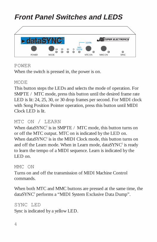
Front Panel Switches and LEDS
POWERWhen the switch is pressed in, the power is on.
MODEThis button steps the LEDs and selects the mode of operation. ForSMPTE / MTC mode, press this button until the desired frame rateLED is lit: 24, 25, 30, or 30 drop frames per second. For MIDI clockwith Song Position Pointer operation, press this button until MIDIClock LED is lit.
MTC ON / LEARNWhen dataSYNC2 is in SMPTE / MTC mode, this button turns onor off the MTC output. MTC on is indicated by the LED on.When dataSYNC2 is in the MIDI Clock mode, this button turns onand off the Learn mode. When in Learn mode, dataSYNC2 is readyto learn the tempo of a MIDI sequence. Learn is indicated by theLED on.
MMC ONTurns on and off the transmission of MIDI Machine Controlcommands.
When both MTC and MMC buttons are pressed at the same time, thedataSYNC2 performs a “MIDI System Exclusive Data Dump”.
SYNC LEDSync is indicated by a yellow LED.
33
Choosing MIDI Clock or SMPTE / MTCIf your sequencer reads MIDI Clock, but cannot read MTC, thenchoose MIDI Clock. MIDI Clock is used for hardware sequencers,workstations, and drum machines, including devices by Alesis,Roland, Kawai, Yamaha, Korg, Ensoniq, Emu, etc. This allows theADAT to control these devices starting at any place in tape.dataSYNC2 will synchronize these machines during tape play back,overdubs, and mix down.
dataSYNC2 decodes the previously learned tempo map and sends aMIDI Song Position Pointer. The sequencer responds by chasing tothe appropriate measure in the song. Then dataSYNC2 will generateMIDI Clocks, so that the sequencer stays in perfect sync.
If your sequencer or hard disk recorder reads MTC, then chooseSMPTE / MTC. SMPTE and MTC are used for nearly all sequencingsoftware packages and hard disk recorders.
SMPTE / MTC allows greater flexibility in that you can makechanges to the starting time, length and tempo of a song or sequenceeven after the your project is well under way.
POWER MODE
MIDICLOCK
LEARN
MTC ON
25 3024 D
MMC ON SYNC
5
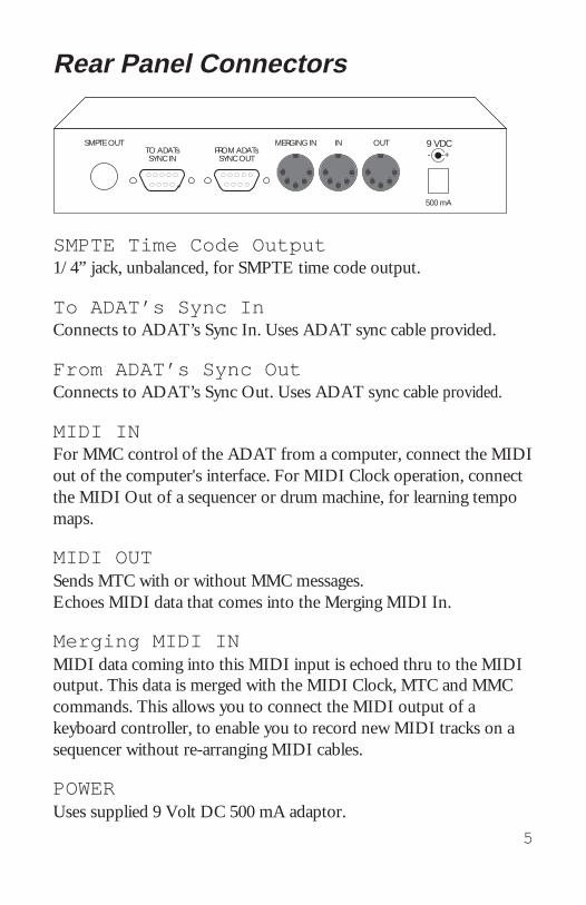
Rear Panel Connectors
SMPTE Time Code Output1/4” jack, unbalanced, for SMPTE time code output.
To ADAT’s Sync InConnects to ADAT’s Sync In. Uses ADAT sync cable provided.
From ADAT’s Sync OutConnects to ADAT’s Sync Out. Uses ADAT sync cable provided.
MIDI INFor MMC control of the ADAT from a computer, connect the MIDIout of the computer's interface. For MIDI Clock operation, connectthe MIDI Out of a sequencer or drum machine, for learning tempomaps.
MIDI OUTSends MTC with or without MMC messages.Echoes MIDI data that comes into the Merging MIDI In.
Merging MIDI INMIDI data coming into this MIDI input is echoed thru to the MIDIoutput. This data is merged with the MIDI Clock, MTC and MMCcommands. This allows you to connect the MIDI output of akeyboard controller, to enable you to record new MIDI tracks on asequencer without re-arranging MIDI cables.
POWERUses supplied 9 Volt DC 500 mA adaptor.
32
SMPTE FormatThe frame rate may be either 24 frames per second (used for 35 mmfilm), 25 frames per second (European and Australian video), 30frames per second (general purpose tape sync), or 30 drop-frame(U.S. video). The 30 drop-frame format selectively removes certainframes to create an average of 29.97 frames per second.
The dataSYNC2 generates any of these forms of SMPTE. When thedataSYNC2 is generating SMPTE, it also may send MIDI Time Code.
MIDI Time Code (MTC)MTC is a way of sending SMPTE time on a MIDI cable. Whilegenerating SMPTE, the dataSYNC2 can directly convert the hour,minute, second, frame data into MTC, which your computer in turncan decode and sync to.
MTC is very different from ordinary MIDI Clock. This is becauseMIDI Clock messages are sent out at a rate that varies with thetempo. That is to say, the faster the sequence, the faster the MIDIClock messages are transmitted. MTC however does not varyin tempo. Rather, it represents a steadily “upcounting” numberstream that can be decoded by a computer to represent a time.
For this reason, sequencers and hard disk recorders that read MTCmust also allow the user to specify a start time. In addition,sequencers (but not hard disk recorders) allow the user to entertempos. So the software is providing the "tempo map" saved as partof a sequence.
In SMPTE / MTC Mode, as soon as the tape begins to play, thedataSYNC2 immediately converts the 48 K sample clock into SMPTEand MTC. But the sequencer or hard disk recorder will not start untilthe SMPTE time equals the pre-programmed starting time.
MERGING IN IN OUTSMPTE OUTTO ADATsSYNC IN
FROM ADATsSYNC OUT
9 VDC+-
500 mA
6
Read This Before Getting Started!The dataSYNC2 produces several kinds of synchronization formats.To get started using the dataSYNC2, you must first determine yoursynchronization requirements.
Regarding MIDI synchronization, it is vitally important to understandthat MIDI Time Code (MTC) is not the same thing as MIDI Clockand Song Position Pointer. Some sequencers read only MIDI Clock,other sequencers read both MIDI Clock and MIDI Time Code.Fortunately, the dataSYNC2 produces both!
But the way that the two synchronization methods are used areradically different. You must be certain which kind of MIDIcommands are required for your application before starting to workwith the dataSYNC2.
Fortunately again, its not really a matter of guess work. The kind ofMIDI synchronization required is usually clearly documented. But doyour research first, which usually starts by reading the chapters onsynchronization in the owners manual for the software or hardwarethat you want to synchronize.
Here are some pointers to help out. For a much more detaileddiscussion of the synchronization terms that are used in this manual,turn to the appendix at the end of the manual.
MIDI Clock and Song Position Pointer.This is the means of synchronizing drum machines, keyboardworkstation sequencers, “hardware” sequencers, and a few software-based sequencers to the ADAT.
Select this dataSYNC2 mode of operation by pressing the Modebutton until the MIDI Clock led is lit.
31
Song Position PointerSong Position Pointer is a MIDI message that indicates how manysixteenth notes have elapsed since the beginning of a song.
MIDI Song Position Pointer by itself cannot synchronize anything. Itmust be used along with MIDI Continue and MIDI Clock messagesto be useful.
The MIDI Song Position Pointer message is sent out only once whenthe dataSYNC2 is in MIDI Clock mode and the ADAT is put intoplay at some location other than the beginning of the song. MIDISong Position Pointer is never sentcontinually.
A sequencer that has been set up to receive MIDI Clock will slave itstempo to MIDI Clocks coming from the dataSYNC2. When the tapeis started, dataSYNC2 sends a Song Position Pointer message into thesequencer. If the sequencer can recognize the message, it willinternally prepare to playback at the right location within the song.
SMPTESMPTE was developed in the 1960’s as a way to uniquely numbereach frame of a video tape for the purposes of editing. On audiotape, SMPTE consists of an sync tone that is recorded onto onetrack. One might say that the tone is recorded along the length of thetape. For this reason, it is known as Longitudinal Time Code orsimply LTC. (There are other ways of encoding SMPTE onto variousmedia, but we will limit the scope of our discussion to LTC.)
7
SMPTE and MIDI Time Code (MTC)This is the means of synchronizing most software sequencers andhard disk-based digital audio workstations. You may also use SMPTEor MTC to synchronize other modular digital multitrack taperecorders, or “machine synchronizers” that lock up analoguemachines and video tape recorders.
Select this dataSYNC2 mode of operation by pressing the Modebutton until the one of the frame rate LEDs is lit. The dataSYNC2
defaults to 30 frames per second, which is fine in the U.S. for mostaudio work that does not involve video.
If you need SMPTE output, but do not want MTC, you may disablethe dataSYNC2’s MTC output by pressing the MTC ON button sothat the MTC LED is not lit.
Syncing with Both SMPTE / MTC and MIDIClockThe dataSYNC2 cannot produce both MTC and MIDI Clock at thesame time. However, some software sequencers, such as Mark of theUnicorn’s Performer™, and Opcode’s Vision™, have the ability tosend MIDI Clock commands while reading MTC.
Therefore, if you have a sequencer with this capability, it is possibleto simultaneously synchronize both a software sequencer and ahardware drum machine. Use the SMPTE / MTC mode of thedataSYNC2. Also connect the MIDI Output of the computer’s MIDIInterface to the MIDI input of a hardware sequencer or drummachine. Follow the instructions for the sequencer with regard tosending out MIDI Clock while receiving MIDI Time Code.
If the sequencer does not have this capability, you may send theSMPTE output of the dataSYNC2 into a SMPTE to MIDI Clockconverter, such as the JLCooper PPS-100 SMPTE Synchronizer /Event Generator.
30
Synchronization TermsThis chapter provides you with definitions of the synchronizationterms that relate to the dataSYNC2. We will conclude with adiscussion of the criteria for choosing the ideal synchronizationprocedure for your application.
Although you probably already have an application for thedataSYNC2 in mind, you might find it helpful to review this chapterbecause there still seems to be a good deal of confusion in theindustry over the differences between MIDI Clock and MIDI TimeCode.
We have for the most part avoided the use of the term “MIDI Sync”in this manual. Although that term used to refer to MIDI Clock,these days it may refer to anything, and thus has become almostuseless as an expression! This confusion is not helped by the fact thatmore than one popular sequencer manufacturer invents their ownsync terminology, using words not even found in the Detailed MIDISpecification. This leaves many musicians, engineers, and producersjustifiably perplexed.
Definition of TermsMIDI Clock with Song Position PointerGenerally, these terms are also used to refer to a whole group ofMIDI messages, including Start, Stop, and Continue.
MIDI Clock is known as a Real Time MIDI message. It is sent andreceived by most sequencers and drum machines continually,24 times each quarter note. Thus the clock rate varies with thetempo. Nearly all sequencers can read MIDI Clock. (Continued.)

8
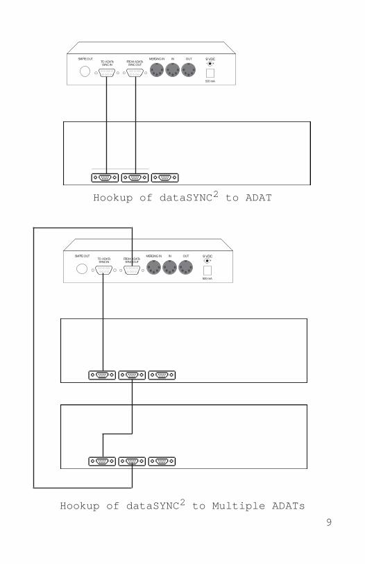
HookupConnect both ADAT Sync Cables� Connect a sync cable. One end plugs into the dataSYNC2
connector labeled TO ADATs SYNC IN.The other end of the cable plugs into the SYNC INconnector on the back of the ADAT.
� Connect a sync cable. One end plugs into the dataSYNC2
connector labeled FROM ADATs SYNC OUT.The other end of the cable plugs into the SYNC OUTconnector on the back of the ADAT.
With Multiple ADATsFor multiple ADAT systems, the ADATs are chained together byconnecting the SYNC OUT of the first ADAT to the SYNC IN ofthe next ADAT.
The dataSYNC2’s TO ADATs SYNC IN connects to SYNC IN onthe first ADAT.
The dataSYNC2’s FROM ADATs SYNC OUT connects to theSYNC OUT of the last ADAT in the chain.
Up to 16 ADATs may be chained in this manner.
Refer to the illustrations.
29
For the most accurate timing, it is recommended that MTC be sentinto a different computer port than the keyboard.
Another solution is to temporarily set the sequencer to internal clock.Then record the new keyboard track on the sequencer, without thetape playing. Then, set the sequencer back to external MIDI Clock orMTC.
No ResponseIf none of the buttons do anything, and none of the LEDs are on,check that the unit is connected to the correct transformer. If theLEDs just stay on, this may indicate that the internal microprocessoris not running. Perhaps the unit has received an AC surge. Turn thepower off and on once to see if the unit returns to life.
ServiceThe most common cause of mysterious problems is a “noisy” ACoutlet. We recommend the use of a AC surge suppressor and linefilter with all computer-related equipment. These can be purchased atany hardware or computer store, and many music stores also nowcarry them.
Your dataSYNC2 is covered in the United States by a one year limitedwarranty. As you might expect, there are no user-serviceable partsinside the dataSYNC2. Refer to the really fine print at the end of thismanual for detailed warranty and service information.
928
The SYNC LED Turns Off (“Drops Out”) During LearnThe minimum tempo must not be below 25 quarter-notes perminute.
If the LED is steadily flashing after the drop out, you have exceededthe memory of the dataSYNC2 and the last tempo map was notrecorded.
Inaccurate ChasingFirst verify that the sequencer or drum machine is indeed set toexternal MIDI Clock. If you have inadvertently left the sequencer ordrum machine set to internal clock, it may still give the illusion oflocking to MIDI Clock. But it will not chase or sync properly.
(This is not a concern with Alesis sequencers and drum machines.These have a single setting for both internal and MIDI clock.)
The Sequencer is Not Playing BackIf the tape is playing and the SYNC LED is on, check that thesequencer has been set up to read external MIDI Clock (sometimescalled “standard beat clocks”). If using a Macintosh computer, checkthe software for correct MIDI port configurations and interface clockrate.
Timing Inaccuracies When Using the Merging InputA keyboard performance with after touch may produce large volumesof MIDI data. If this data comes into a sequencer at the same time asMIDI Clock or MTC, timing inaccuracies may result as the MIDIband width becomes full.
Also, some sequencing software packages do not permit you tosimultaneously send keyboard performance data and MTC into thesame computer port.
MERGING IN IN OUTSMPTE OUTTO ADATsSYNC IN
FROM ADATsSYNC OUT
9 VDC+-
500 mA
Hookup of dataSYNC2 to Multiple ADATs
MERGING IN IN OUTSMPTE OUTTO ADATsSYNC IN
FROM ADATsSYNC OUT
9 VDC+-
500 mA
Hookup of dataSYNC2 to ADAT

10 27
MMCIf the symptom is that the ADAT is responding intermittently toMMC commands coming from a computer, the dataSYNC2 may havebeen turned on first instead of last. Turn the ADAT on first, andthen turn on the dataSYNC2.
If you have more than one ADAT, after turning them on, let them gothrough their automatic ID process. Then turn on the dataSYNC2.
This is necessary because the dataSYNC2 sends some importantcommands to the ADAT at the moment that the dataSYNC2 isturned on. If the units are powered up in the wrong order, theADATs will never receive these important commands, and somefeatures of the dataSYNC2 will appear to not operate correctly.
MIDI Clock and Song Position PointerThe SYNC LED Does Not Flicker When Attempting to Learn theTempo Map.Check that the sequencer or drum machine is really set up to put outMIDI Clocks. A surprising number of devices need to be “told” todo this.
The MIDI cable should go from the MIDI out of the sequencer tothe MIDI in of the dataSYNC2, and the LEDs should indicate MIDIClock and LEARN.
If the memory is full, all the LEDs will flash and you will not be ableto learn additional tempo maps.
The SYNC LED Does Not Come On When Playing Back.Make sure that you are playing a section of the tape that falls withinthe start and end of the tempo map.
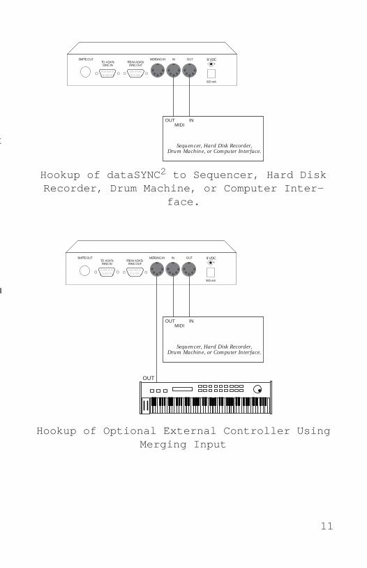
MIDI ConnectionsBasic System� Connect a MIDI cable from the dataSYNC2 MIDI Out to the
MIDI input of the sequencer, drum machine or hard diskrecorder. If the system you are synchronizing is software based,this cable will usually be connected to a MIDI Interface on acomputer.
You might also connect this cable to a MIDI Patch Bay, such as theJLCooper Synapse™. This would allow you to programmablydistribute the MTC and MMC data to any suitable MIDI equipmentin the studio. (The Synapse also provides a large, easy to read MTCdisplay.)
� Connect a MIDI cable from the dataSYNC2 MIDI In to theMIDI output of the sequencer, drum machine or hard diskrecorder. If the system you are synchronizing is software based,this cable will usually be connected to a MIDI Interface on acomputer.
With an External MIDI Controller (Optional)� Connect a MIDI cable from the output of a keyboard or fader
controller to the dataSYNC2 Merging In.
Notes played on the keyboard, or Controller commands from a fadercontroller, will pass through the dataSYNC2 and into the sequencer.This is useful for recording new sequencer tracks, without having topull and re-arrange MIDI cables.
To Allow Sequencer to Play a Keyboard / Tone Module� Start with either hookup diagram on opposite page.
Connect the MIDI Out of the sequencer or computer to theMIDI In of the keyboard. Connect the MIDI Thru of thekeyboard to the dataSYNC2 MIDI In.
Set the keyboard to "local off" to avoid a loop.
1126
MERGING IN IN OUTSMPTE OUTTO ADATsSYNC IN
FROM ADATsSYNC OUT
9 VDC+-
500 mA
Sequencer, Hard Disk Recorder,Drum Machine, or Computer Interface.
OUT INMIDI
Sequencer, Hard Disk Recorder,Drum Machine, or Computer Interface.
OUT INMIDI
MERGING IN IN OUTSMPTE OUTTO ADATsSYNC IN
FROM ADATsSYNC OUT
9 VDC+-
500 mA
OUT
Hookup of dataSYNC2 to Sequencer, Hard DiskRecorder, Drum Machine, or Computer Inter-
face.
Hookup of Optional External Controller UsingMerging Input
TroubleshootingIf you have followed the directions, but things still are not going quite as youexpected, take a few minutes to do some troubleshooting.
Here are some clues to solve common problems.
Flashing LEDs (Full Memory Indication)In MIDI Clock mode, when memory becomes full, all the LEDs will flash. Atthat point, the tempo of the last song has not been recorded.
This flashing memory full warning keeps going even if you stop the tape. Tocontinue to use the dataSYNC2, turn it off and back on again.
SMPTE and MIDI Time CodeThe symptom is that the sequence immediately chases to the wrong measurenumber as soon as the tape is started.
The Start Time of the sequencer has probably not been set correctly. (This issometimes called Offset Time.) Let the tape run for a few seconds so that youcan observe the SMPTE time display on your sequencer.
If the sequence skips ahead only a few measures, then you did not enter anadditional arbitrary offset to allow for some tape leader. That is, if you wantthe sequenced song to start when the ADAT's counter reads, say, 20 seconds,then your SMPTE or MTC driven device requires an offset time of00:00:20:00.
12 25
System Exclusive ImplementationFor those of you writing or customizing your own librarian software,here are more technical details about the MIDI System Exclusiveimplementation of the dataSYNC2.
To request a dump of system exclusive data, the storage device mustsend the following commands into the dataSYNC2:(MIDI data is shown in hexadecimal notation, as indicated by the “$”before each number.)
$F0 $15 $20 $00 $F7This is the “dump request” command.
The dataSYNC2 will reply with:$F0 $15 $20 $01 <data> $F7This is a dump of all the tempo maps in memory.
The data is “nibblized”, and may be as long as 16258 bytes.
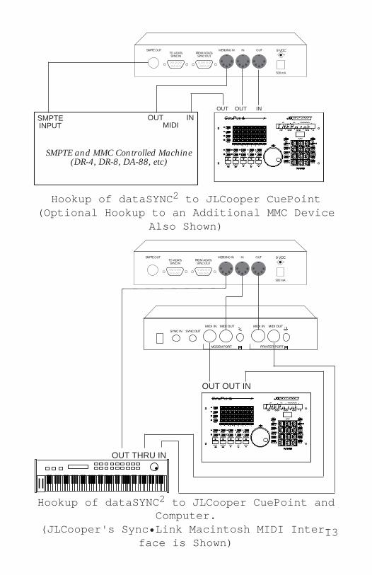
Connecting a JLCooper CuePoint Universal Autolocator� Connect CuePoint to the dataSYNC2 using 2 MIDI cables.
CuePoint MIDI Out to dataSYNC2 MIDI In.CuePoint MIDI In to dataSYNC2 MIDI Out.
Connecting Additional MMC Device (DR-4, DR-8, DA-88)� Connect MIDI Out of CuePoint to MIDI In of the additional
MMC controlled device. Connect the MIDI Out of the additionalMMC device to the dataSYNC2's Merging MIDI In.
Using the Merging In allows CuePoint to receive merged MMC"tallyback" data. This allows CuePoint to keep track of the locationof the ADAT and the additional device.
� Connect SMPTE Time Code Out of dataSYNC2 to the SMPTEtime code input of the additional MMC controlled device.
DA-88s and DR-4s and DR-8s require optional Sync Cards to be ableto read SMPTE time code to slave to the ADAT.
Connecting CuePoint, Computer, and MIDI ControllerThis hookup diagram, though complicated in appearance, allowseither CuePoint or a Computer to control the ADAT.A dual port MIDI interface is required, such as JLCooper's Sync•LinkMacintosh MIDI interface.
The software must have the ability to send MMC commands.The software's MIDI Echo (or "thru) feature must also be turned onfor both ports. The keyboard controller must be set to "local off".
A keyboard performance passes through dataSYNC2 and is recordedon the sequencer, via the interface's "Printer In".The performance is played back from the "Printer Out".
CuePoint's commands go into the interface's "Modem In".The "Modem Out" sends both CuePoint and Computer commandsinto the dataSYNC2 to control the ADAT.
1324
To Backup the dataSYNC2 MemoryIf you are working in MIDI Clock, it is possible to backup the tempomap memory of the dataSYNC2. Backup is not necessary if you areworking in SMPTE / MTC mode.
To backup the memory of the dataSYNC2 requires a computerrunning a MIDI System Exclusive librarian program, or a MIDI datadisk, or a sequencer that can record System Exclusive data.
If you have the necessary equipment, backup is recommend forseveral reasons. For one thing, you can only program the tempomaps for one tape at a time into the dataSYNC2 . You have to clearmemory every time you want to work with a new tape. Thus it isuseful to have an “archive” copy of the tempo maps in case you wantto remix the songs in the future. A backup also protects you againstdata loss in case of equipment failure or power surges.
To backup the memory, connect the MIDI input of the data storagedevice to the MIDI output of dataSYNC2.
Set up the data storage device to receive dataSYNC2’s data dump.
Press both the MTC and the MMC switches at the same time toinitiate the data dump.
To load the data back into the dataSYNC2, simply send the data intothe dataSYNC2’s MIDI input. It doesn’t matter what the switchsettings are. The dataSYNC2 will receive the data at any time,provided that it is not in a SYNC condition.
Hookup of dataSYNC2 to JLCooper CuePoint(Optional Hookup to an Additional MMC Device
Also Shown)
SMPTE and MMC Controlled Machine(DR-4, DR-8, DA-88, etc)
OUT INMIDI
SMPTEINPUT
MERGING IN IN OUTSMPTE OUTTO ADATsSYNC IN
FROM ADATsSYNC OUT
9 VDC+-
500 mA
OUT OUT IN
Hookup of dataSYNC2 to JLCooper CuePoint andComputer.
(JLCooper's Sync•Link Macintosh MIDI Inter-face is Shown)
MERGING IN IN OUTSMPTE OUTTO ADATsSYNC IN
FROM ADATsSYNC OUT
9 VDC+-
500 mA
SYNC IN SYNC OUT
MIDI IN MIDI OUT
MODEM PORT
MIDI IN
PRINTER PORT
MIDI OUT
OUT THRU IN
OUT OUT IN
14 23
To Playback in Sync� After the dataSYNC2 has learned the tempo maps of yoursequences, set your sequencer for external MIDI clock.
� Check that the dataSYNC2 mode is still set to MIDI Clock.If not, press the Mode button until the MIDI Clock LED is lit.
� Take the dataSYNC2 out of Learn mode by pressing theMTC / LEARN button so the LED is off.
� Start the ADAT tape, either from just ahead of the start ofthe song, or from where ever within the song you desire.
The SYNC LED will flash slowly if you start the tape before the songbegins. When the song starts, the SYNC LED will come on solid,and the sequencer will start.
If this is at the very beginning of the track, a MIDI Start command,followed by MIDI Clocks will be sent from the dataSYNC2 into thesequencer or drum machine.
If the tape is started anywhere later than the very start, a MIDI SongPosition Pointer command will be sent, followed by a MIDIContinue command, and then MIDI Clocks.
The sequencer/drum machine will “chase” to the appropriate placein the song. From there, it will stay in perfect sync.
Power On SequenceTurn the ADAT on first, and then turn on the dataSYNC2.
If you have more than one ADAT, after turning them on, let them gothrough their automatic ID process. Then turn on the dataSYNC2.
This is necessary because the dataSYNC2 sends some importantcommands to the ADAT at the moment that the dataSYNC2 isturned on. If the units are powered up in the wrong order, theADATs will never receive these commands, and some features of thedataSYNC2 will appear to not operate correctly.
15
Sample Rate SelectionThe dataSYNC2 version 2.0 supports both 44.1 K and 48 K samplerates. On the original ADAT, the sample rate was 48 K. On theADAT XT, the sample rate is user selectable to either 44.1 K or 48K.
Automatic Sample Rate SelectiondataSYNC2 will automatically detect the sample rate of the ADAT orADAT XT. It is not necessary to set anything on the dataSYNC2,unless you plan on using pitch shift.
Manual Sample Rate Selection and PitchShiftThe dataSYNC2 maintains sync even when the pitch is shifted.
Changing the pitch on the ADAT or ADAT XT actually changes thesample rate. When the pitch is shifted more than about 3%, the twosample rates cannot be distinguished. (In other words, you can slowdown 48 K enough so it appears to be 44.1 K, and vice versa.) Thisproblem is easily overcome by setting the dataSYNC2’s sample ratemanually.
If you plan on using pitch shift, then you should set the dataSYNC2’ssample rate manually as follows:
• To manually set the dataSYNC2 to 44.1 K sample rate operation,press and hold the MTC button on power up.
• To manually set the dataSYNC2 to 48 K sample rate operation,press and hold the MMC button on power up.
Once the sample rate has been manually set, you can use pitch shiftwithout the dataSYNC2 automatically changing sample rates.
It will remain in the selected rate until the unit is powered-down.
22
Full Memory IndicationWhen memory becomes full, the SYNC LED with no longer blinkrapidly at a rate related to the tempo of the song. Instead, all theLEDs will flash. At that point, the tempo of the last song has notbeen recorded.
This flashing memory full warning keeps going even if you stop thetape. This way you are sure to not miss this memory full conditionindicator. To continue to use the dataSYNC2, turn it off and back onagain.
To free up memory, you can replace a song at any point in the tape.Simply cue up the ADAT tape and start the sequencer. If you startthe sequencer at a point in tape where a tempo map already exists,the new tempo map will replace the older one.
16
MTC and SMPTE OperationThe dataSYNC2 outputs SMPTE time code, with or without MTC.MTC is used to synchronize MIDI sequencers and digital audioworkstations. SMPTE time code may be used to drive any devicewith a SMPTE time code input, including mixing console automationsystems and machine synchronizers.
The time code is equal to the tape counter of the ADAT.
In the 2 minute "dAtA" section of the beginning of the tape, the timecode output counts up from 23:58:00:00.
When the ADAT’s counter reads 00:00, the SMPTE and MTCoutput of the dataSYNC2 is equal to 00:00:00:00.
Important!Set dataSYNC2 to SMPTE / MTC mode by selecting a frame rate withthe Mode button.
To set the dataSYNC2 to output SMPTE and MTC, make sure thatone of the frame rate LEDs is lit.
Frame rate selectionPress the button until desired frame rate LED is lit.� 24 frames per second (used for 35 mm film)� 25 frames per second (European Video)� 30 frames per second (General purpose audio sync)� 30-drop frames per second (U.S. Video)
This is actually 29.97 drop frames per second.
21
If the sequencer is the kind that doesn’t stop itself, but rather it keepsrunning after there are no more notes, then stop the sequenceyourself. Then stop the ADAT tape.
The dataSYNC2 has now recorded the “tempo map” of the sequence.That is, it knows when the sequence starts, every tempo change, andwhen the sequence stops. All of this information is carefullycalculated to line up exactly with the ADAT tape.
To learn the tempo of additional sequences, simply cue the ADATtape to the place on the tape where you want the next song to start.This can be anytime after the end of the first song. Again, press Playon the ADAT, followed by Play on the sequencer.
Continue to repeat this procedure for each sequence.
The dataSYNC2 holds multiple song tempo maps in itsbattery-backed memory. It holds up to a maximum of 16 songs forone ADAT tape.
The actual available memory will vary with the meter, tempo, andnumber of tempo changes in each song.
For example, if a 5 minute song has almost continuous rubato tempochanges, you might be only able to get 5 or 6 songs on tape beforethe memory becomes full. Fast tempos eat up more memory thanslow tempos.
17
MMC ON / OFFThis button only affects whether the dataSYNC2 sends MMC.When MMC is on, MMC commands generated by the ADAT aresent out of the dataSYNC2’s MIDI output.
If you are not specifically using MMC, leave this control set to off.MMC is a recent addition to the MIDI specification. So some oldersequencers may not react to it predictably.
MMC commands sent by dataSYNC2 initiated by ADAT’s transportcontrols.� Deferred Play� Pause� Record� Rewind� Fast Forward� Search
The MMC Button Only Affects the dataSYNC2 MIDI OutThe state of the MMC button does not affect the ability of thedataSYNC2 to receive MMC. It is not necessary to turn "MMCON" in order to receive MMC from, for example, a softwareapplication or a JLCooper CuePoint.
MTC ON / OFFEnables or disables the output of MTC from the dataSYNC2.
NoteWhile the ADAT is playing, the buttons are temporarily disabled andthe state of the MMC and the MTC functions cannot be changed.
20
To Clear dataSYNC2 MemorydataSYNC2 holds tempo information for one ADAT tape.When you change tapes to start on a new project, clear thedataSYNC2's memory by doing the following:� Check that the dataSYNC2 is in MIDI Clock mode.
Press the Learn button so the LED is lit.
� Press and do not release the Learn and MMC buttons.While holding in Learn and MMC, press the Mode button.Release all three buttons.
� The LEDs blink quickly three times to confirm that thememory has been cleared.
To Record Tempos (“LEARN the TempoMap”)� After recording your sequencer tracks (or drum machinetracks), leave your sequencer set for internal clock.
� Also be certain that your sequencer is set up to transmit(send) MIDI clocks.
� Check that the dataSYNC2 has been set to MIDI Clock.If not, press the Mode button until the MIDI Clock LED is lit.
� Set the dataSYNC2 to Learn mode by pressing the MTC /Learn button so the LED is lit.
� Cue the ADAT tape to any location after 00.00.
� Start the tape. The SYNC LED on dataSYNC2 flashes slowly.That indicates that the dataSYNC2 is in Learn mode and isprepared to learn the tempo of the sequence.
� Start the Sequencer. You should immediately see the SYNCled begin to flash rapidly. (If the tempo of the song changes,the flash rate will change, too.)
� A few seconds after the sequence stops, stop the ADAT.
18 19
Setting Software Start TimeA sequencer or hard disk recorder that receives MTC must be told atwhat SMPTE time to start. This is usually called MTC offset time,though sometimes it is simply called start time, or in the case of Markof the Unicorn’s Performer, “Chunk Start”.
The dataSYNC2 starts generating MTC at 23:58:00:00. This happensduring the two minutes when the ADAT displays the word dAtA.When the ADAT’s time indicator reads 00:00, the dataSYNC’s MTCoutput is at 00:00:00:00.
Your sequencer start time should be later than 00.For example, use a start time of, say, 00:00:20:00.
This allows 20 seconds of ADAT tape to play before the sequencestarts.
On the MIDI software, set it to slave to MTC.
Verify that your software is set up to communicate to the computer’sMIDI interface on the correct serial port.
MIDI Clock OperationThe dataSYNC2 outputs MIDI Clock and Song Position Pointer.This mode is required to synchronize hardware sequencers, drummachines, and workstation keyboards, as well as some older softwaresequencers.
Important!Set the Mode to MIDI Clock for MIDI Clock OperationTo set the dataSYNC2 to output MIDI Clock and Song PositionPointer, press the Mode button until the MIDI Clock LED is lit.
Some Requirements before proceeding:A Completed Sequenced Song is NeededThe dataSYNC2 needs to learn the tempo and length of a sequence. Itdoes this by reading the MIDI Clocks as they come out of thesequencer. Therefore, the sequence must be recorded first, before thedataSYNC2 can learn the tempo of the sequence.
Suppose that you want to sync up a sequence to the ADAT, but youhaven’t yet finished working on the sequence. In that case, you needat least one sequencer track that runs the length of the song, at thecorrect tempo.
If you do not have even one track completed yet, then make adummy (blank) track on your sequencer of the correct length andtempo.
The Sequencer Must be Set to Send MIDI ClocksBe certain that your sequencer is set up to transmit (send) MIDIclocks. It doesn’t matter whether or not it is set up to transmit MIDISong Pointer, since it is the MIDI Clocks that the dataSYNC2 needsto receive to learn the tempo of the song.
Stay Above the Minimum TempoThe minimum tempo of the sequence must not be below 25 quarter-notes per minute.
17
MMC ON / OFFThis button only affects whether the dataSYNC2 sends MMC.When MMC is on, MMC commands generated by the ADAT aresent out of the dataSYNC2’s MIDI output.
If you are not specifically using MMC, leave this control set to off.MMC is a recent addition to the MIDI specification. So some oldersequencers may not react to it predictably.
MMC commands sent by dataSYNC2 initiated by ADAT’s transportcontrols.� Deferred Play� Pause� Record� Rewind� Fast Forward� Search
The MMC Button Only Affects the dataSYNC2 MIDI OutThe state of the MMC button does not affect the ability of thedataSYNC2 to receive MMC. It is not necessary to turn "MMCON" in order to receive MMC from, for example, a softwareapplication or a JLCooper CuePoint.
MTC ON / OFFEnables or disables the output of MTC from the dataSYNC2.
NoteWhile the ADAT is playing, the buttons are temporarily disabled andthe state of the MMC and the MTC functions cannot be changed.
20
To Clear dataSYNC2 MemorydataSYNC2 holds tempo information for one ADAT tape.When you change tapes to start on a new project, clear thedataSYNC2's memory by doing the following:� Check that the dataSYNC2 is in MIDI Clock mode.
Press the Learn button so the LED is lit.
� Press and do not release the Learn and MMC buttons.While holding in Learn and MMC, press the Mode button.Release all three buttons.
� The LEDs blink quickly three times to confirm that thememory has been cleared.
To Record Tempos (“LEARN the TempoMap”)� After recording your sequencer tracks (or drum machinetracks), leave your sequencer set for internal clock.
� Also be certain that your sequencer is set up to transmit(send) MIDI clocks.
� Check that the dataSYNC2 has been set to MIDI Clock.If not, press the Mode button until the MIDI Clock LED is lit.
� Set the dataSYNC2 to Learn mode by pressing the MTC /Learn button so the LED is lit.
� Cue the ADAT tape to any location after 00.00.
� Start the tape. The SYNC LED on dataSYNC2 flashes slowly.That indicates that the dataSYNC2 is in Learn mode and isprepared to learn the tempo of the sequence.
� Start the Sequencer. You should immediately see the SYNCled begin to flash rapidly. (If the tempo of the song changes,the flash rate will change, too.)
� A few seconds after the sequence stops, stop the ADAT.
16
MTC and SMPTE OperationThe dataSYNC2 outputs SMPTE time code, with or without MTC.MTC is used to synchronize MIDI sequencers and digital audioworkstations. SMPTE time code may be used to drive any devicewith a SMPTE time code input, including mixing console automationsystems and machine synchronizers.
The time code is equal to the tape counter of the ADAT.
In the 2 minute "dAtA" section of the beginning of the tape, the timecode output counts up from 23:58:00:00.
When the ADAT’s counter reads 00:00, the SMPTE and MTCoutput of the dataSYNC2 is equal to 00:00:00:00.
Important!Set dataSYNC2 to SMPTE / MTC mode by selecting a frame rate withthe Mode button.
To set the dataSYNC2 to output SMPTE and MTC, make sure thatone of the frame rate LEDs is lit.
Frame rate selectionPress the button until desired frame rate LED is lit.� 24 frames per second (used for 35 mm film)� 25 frames per second (European Video)� 30 frames per second (General purpose audio sync)� 30-drop frames per second (U.S. Video)
This is actually 29.97 drop frames per second.
21
If the sequencer is the kind that doesn’t stop itself, but rather it keepsrunning after there are no more notes, then stop the sequenceyourself. Then stop the ADAT tape.
The dataSYNC2 has now recorded the “tempo map” of the sequence.That is, it knows when the sequence starts, every tempo change, andwhen the sequence stops. All of this information is carefullycalculated to line up exactly with the ADAT tape.
To learn the tempo of additional sequences, simply cue the ADATtape to the place on the tape where you want the next song to start.This can be anytime after the end of the first song. Again, press Playon the ADAT, followed by Play on the sequencer.
Continue to repeat this procedure for each sequence.
The dataSYNC2 holds multiple song tempo maps in itsbattery-backed memory. It holds up to a maximum of 16 songs forone ADAT tape.
The actual available memory will vary with the meter, tempo, andnumber of tempo changes in each song.
For example, if a 5 minute song has almost continuous rubato tempochanges, you might be only able to get 5 or 6 songs on tape beforethe memory becomes full. Fast tempos eat up more memory thanslow tempos.
15
Sample Rate SelectionThe dataSYNC2 version 2.0 supports both 44.1 K and 48 K samplerates. On the original ADAT, the sample rate was 48 K. On theADAT XT, the sample rate is user selectable to either 44.1 K or 48K.
Automatic Sample Rate SelectiondataSYNC2 will automatically detect the sample rate of the ADAT orADAT XT. It is not necessary to set anything on the dataSYNC2,unless you plan on using pitch shift.
Manual Sample Rate Selection and PitchShiftThe dataSYNC2 maintains sync even when the pitch is shifted.
Changing the pitch on the ADAT or ADAT XT actually changes thesample rate. When the pitch is shifted more than about 3%, the twosample rates cannot be distinguished. (In other words, you can slowdown 48 K enough so it appears to be 44.1 K, and vice versa.) Thisproblem is easily overcome by setting the dataSYNC2’s sample ratemanually.
If you plan on using pitch shift, then you should set the dataSYNC2’ssample rate manually as follows:
• To manually set the dataSYNC2 to 44.1 K sample rate operation,press and hold the MTC button on power up.
• To manually set the dataSYNC2 to 48 K sample rate operation,press and hold the MMC button on power up.
Once the sample rate has been manually set, you can use pitch shiftwithout the dataSYNC2 automatically changing sample rates.
It will remain in the selected rate until the unit is powered-down.
22
Full Memory IndicationWhen memory becomes full, the SYNC LED with no longer blinkrapidly at a rate related to the tempo of the song. Instead, all theLEDs will flash. At that point, the tempo of the last song has notbeen recorded.
This flashing memory full warning keeps going even if you stop thetape. This way you are sure to not miss this memory full conditionindicator. To continue to use the dataSYNC2, turn it off and back onagain.
To free up memory, you can replace a song at any point in the tape.Simply cue up the ADAT tape and start the sequencer. If you startthe sequencer at a point in tape where a tempo map already exists,the new tempo map will replace the older one.
14 23
To Playback in Sync� After the dataSYNC2 has learned the tempo maps of yoursequences, set your sequencer for external MIDI clock.
� Check that the dataSYNC2 mode is still set to MIDI Clock.If not, press the Mode button until the MIDI Clock LED is lit.
� Take the dataSYNC2 out of Learn mode by pressing theMTC / LEARN button so the LED is off.
� Start the ADAT tape, either from just ahead of the start ofthe song, or from where ever within the song you desire.
The SYNC LED will flash slowly if you start the tape before the songbegins. When the song starts, the SYNC LED will come on solid,and the sequencer will start.
If this is at the very beginning of the track, a MIDI Start command,followed by MIDI Clocks will be sent from the dataSYNC2 into thesequencer or drum machine.
If the tape is started anywhere later than the very start, a MIDI SongPosition Pointer command will be sent, followed by a MIDIContinue command, and then MIDI Clocks.
The sequencer/drum machine will “chase” to the appropriate placein the song. From there, it will stay in perfect sync.
Power On SequenceTurn the ADAT on first, and then turn on the dataSYNC2.
If you have more than one ADAT, after turning them on, let them gothrough their automatic ID process. Then turn on the dataSYNC2.
This is necessary because the dataSYNC2 sends some importantcommands to the ADAT at the moment that the dataSYNC2 isturned on. If the units are powered up in the wrong order, theADATs will never receive these commands, and some features of thedataSYNC2 will appear to not operate correctly.
1324
To Backup the dataSYNC2 MemoryIf you are working in MIDI Clock, it is possible to backup the tempomap memory of the dataSYNC2. Backup is not necessary if you areworking in SMPTE / MTC mode.
To backup the memory of the dataSYNC2 requires a computerrunning a MIDI System Exclusive librarian program, or a MIDI datadisk, or a sequencer that can record System Exclusive data.
If you have the necessary equipment, backup is recommend forseveral reasons. For one thing, you can only program the tempomaps for one tape at a time into the dataSYNC2 . You have to clearmemory every time you want to work with a new tape. Thus it isuseful to have an “archive” copy of the tempo maps in case you wantto remix the songs in the future. A backup also protects you againstdata loss in case of equipment failure or power surges.
To backup the memory, connect the MIDI input of the data storagedevice to the MIDI output of dataSYNC2.
Set up the data storage device to receive dataSYNC2’s data dump.
Press both the MTC and the MMC switches at the same time toinitiate the data dump.
To load the data back into the dataSYNC2, simply send the data intothe dataSYNC2’s MIDI input. It doesn’t matter what the switchsettings are. The dataSYNC2 will receive the data at any time,provided that it is not in a SYNC condition.
Hookup of dataSYNC2 to JLCooper CuePoint(Optional Hookup to an Additional MMC Device
Also Shown)
SMPTE and MMC Controlled Machine(DR-4, DR-8, DA-88, etc)
OUT INMIDI
SMPTEINPUT
MERGING IN IN OUTSMPTE OUTTO ADATsSYNC IN
FROM ADATsSYNC OUT
9 VDC+-
500 mA
OUT OUT IN
Hookup of dataSYNC2 to JLCooper CuePoint andComputer.
(JLCooper's Sync•Link Macintosh MIDI Inter-face is Shown)
MERGING IN IN OUTSMPTE OUTTO ADATsSYNC IN
FROM ADATsSYNC OUT
9 VDC+-
500 mA
SYNC IN SYNC OUT
MIDI IN MIDI OUT
MODEM PORT
MIDI IN
PRINTER PORT
MIDI OUT
OUT THRU IN
OUT OUT IN
12 25
System Exclusive ImplementationFor those of you writing or customizing your own librarian software,here are more technical details about the MIDI System Exclusiveimplementation of the dataSYNC2.
To request a dump of system exclusive data, the storage device mustsend the following commands into the dataSYNC2:(MIDI data is shown in hexadecimal notation, as indicated by the “$”before each number.)
$F0 $15 $20 $00 $F7This is the “dump request” command.
The dataSYNC2 will reply with:$F0 $15 $20 $01 <data> $F7This is a dump of all the tempo maps in memory.
The data is “nibblized”, and may be as long as 16258 bytes.
Connecting a JLCooper CuePoint Universal Autolocator� Connect CuePoint to the dataSYNC2 using 2 MIDI cables.
CuePoint MIDI Out to dataSYNC2 MIDI In.CuePoint MIDI In to dataSYNC2 MIDI Out.
Connecting Additional MMC Device (DR-4, DR-8, DA-88)� Connect MIDI Out of CuePoint to MIDI In of the additional
MMC controlled device. Connect the MIDI Out of the additionalMMC device to the dataSYNC2's Merging MIDI In.
Using the Merging In allows CuePoint to receive merged MMC"tallyback" data. This allows CuePoint to keep track of the locationof the ADAT and the additional device.
� Connect SMPTE Time Code Out of dataSYNC2 to the SMPTEtime code input of the additional MMC controlled device.
DA-88s and DR-4s and DR-8s require optional Sync Cards to be ableto read SMPTE time code to slave to the ADAT.
Connecting CuePoint, Computer, and MIDI ControllerThis hookup diagram, though complicated in appearance, allowseither CuePoint or a Computer to control the ADAT.A dual port MIDI interface is required, such as JLCooper's Sync•LinkMacintosh MIDI interface.
The software must have the ability to send MMC commands.The software's MIDI Echo (or "thru) feature must also be turned onfor both ports. The keyboard controller must be set to "local off".
A keyboard performance passes through dataSYNC2 and is recordedon the sequencer, via the interface's "Printer In".The performance is played back from the "Printer Out".
CuePoint's commands go into the interface's "Modem In".The "Modem Out" sends both CuePoint and Computer commandsinto the dataSYNC2 to control the ADAT.
1126
MERGING IN IN OUTSMPTE OUTTO ADATsSYNC IN
FROM ADATsSYNC OUT
9 VDC+-
500 mA
Sequencer, Hard Disk Recorder,Drum Machine, or Computer Interface.
OUT INMIDI
Sequencer, Hard Disk Recorder,Drum Machine, or Computer Interface.
OUT INMIDI
MERGING IN IN OUTSMPTE OUTTO ADATsSYNC IN
FROM ADATsSYNC OUT
9 VDC+-
500 mA
OUT
Hookup of dataSYNC2 to Sequencer, Hard DiskRecorder, Drum Machine, or Computer Inter-
face.
Hookup of Optional External Controller UsingMerging Input
TroubleshootingIf you have followed the directions, but things still are not going quite as youexpected, take a few minutes to do some troubleshooting.
Here are some clues to solve common problems.
Flashing LEDs (Full Memory Indication)In MIDI Clock mode, when memory becomes full, all the LEDs will flash. Atthat point, the tempo of the last song has not been recorded.
This flashing memory full warning keeps going even if you stop the tape. Tocontinue to use the dataSYNC2, turn it off and back on again.
SMPTE and MIDI Time CodeThe symptom is that the sequence immediately chases to the wrong measurenumber as soon as the tape is started.
The Start Time of the sequencer has probably not been set correctly. (This issometimes called Offset Time.) Let the tape run for a few seconds so that youcan observe the SMPTE time display on your sequencer.
If the sequence skips ahead only a few measures, then you did not enter anadditional arbitrary offset to allow for some tape leader. That is, if you wantthe sequenced song to start when the ADAT's counter reads, say, 20 seconds,then your SMPTE or MTC driven device requires an offset time of00:00:20:00.
10 27
MMCIf the symptom is that the ADAT is responding intermittently toMMC commands coming from a computer, the dataSYNC2 may havebeen turned on first instead of last. Turn the ADAT on first, andthen turn on the dataSYNC2.
If you have more than one ADAT, after turning them on, let them gothrough their automatic ID process. Then turn on the dataSYNC2.
This is necessary because the dataSYNC2 sends some importantcommands to the ADAT at the moment that the dataSYNC2 isturned on. If the units are powered up in the wrong order, theADATs will never receive these important commands, and somefeatures of the dataSYNC2 will appear to not operate correctly.
MIDI Clock and Song Position PointerThe SYNC LED Does Not Flicker When Attempting to Learn theTempo Map.Check that the sequencer or drum machine is really set up to put outMIDI Clocks. A surprising number of devices need to be “told” todo this.
The MIDI cable should go from the MIDI out of the sequencer tothe MIDI in of the dataSYNC2, and the LEDs should indicate MIDIClock and LEARN.
If the memory is full, all the LEDs will flash and you will not be ableto learn additional tempo maps.
The SYNC LED Does Not Come On When Playing Back.Make sure that you are playing a section of the tape that falls withinthe start and end of the tempo map.
MIDI ConnectionsBasic System� Connect a MIDI cable from the dataSYNC2 MIDI Out to the
MIDI input of the sequencer, drum machine or hard diskrecorder. If the system you are synchronizing is software based,this cable will usually be connected to a MIDI Interface on acomputer.
You might also connect this cable to a MIDI Patch Bay, such as theJLCooper Synapse™. This would allow you to programmablydistribute the MTC and MMC data to any suitable MIDI equipmentin the studio. (The Synapse also provides a large, easy to read MTCdisplay.)
� Connect a MIDI cable from the dataSYNC2 MIDI In to theMIDI output of the sequencer, drum machine or hard diskrecorder. If the system you are synchronizing is software based,this cable will usually be connected to a MIDI Interface on acomputer.
With an External MIDI Controller (Optional)� Connect a MIDI cable from the output of a keyboard or fader
controller to the dataSYNC2 Merging In.
Notes played on the keyboard, or Controller commands from a fadercontroller, will pass through the dataSYNC2 and into the sequencer.This is useful for recording new sequencer tracks, without having topull and re-arrange MIDI cables.
To Allow Sequencer to Play a Keyboard / Tone Module� Start with either hookup diagram on opposite page.
Connect the MIDI Out of the sequencer or computer to theMIDI In of the keyboard. Connect the MIDI Thru of thekeyboard to the dataSYNC2 MIDI In.
Set the keyboard to "local off" to avoid a loop.
928
The SYNC LED Turns Off (“Drops Out”) During LearnThe minimum tempo must not be below 25 quarter-notes perminute.
If the LED is steadily flashing after the drop out, you have exceededthe memory of the dataSYNC2 and the last tempo map was notrecorded.
Inaccurate ChasingFirst verify that the sequencer or drum machine is indeed set toexternal MIDI Clock. If you have inadvertently left the sequencer ordrum machine set to internal clock, it may still give the illusion oflocking to MIDI Clock. But it will not chase or sync properly.
(This is not a concern with Alesis sequencers and drum machines.These have a single setting for both internal and MIDI clock.)
The Sequencer is Not Playing BackIf the tape is playing and the SYNC LED is on, check that thesequencer has been set up to read external MIDI Clock (sometimescalled “standard beat clocks”). If using a Macintosh computer, checkthe software for correct MIDI port configurations and interface clockrate.
Timing Inaccuracies When Using the Merging InputA keyboard performance with after touch may produce large volumesof MIDI data. If this data comes into a sequencer at the same time asMIDI Clock or MTC, timing inaccuracies may result as the MIDIband width becomes full.
Also, some sequencing software packages do not permit you tosimultaneously send keyboard performance data and MTC into thesame computer port.
MERGING IN IN OUTSMPTE OUTTO ADATsSYNC IN
FROM ADATsSYNC OUT
9 VDC+-
500 mA
Hookup of dataSYNC2 to Multiple ADATs
MERGING IN IN OUTSMPTE OUTTO ADATsSYNC IN
FROM ADATsSYNC OUT
9 VDC+-
500 mA
Hookup of dataSYNC2 to ADAT
8
HookupConnect both ADAT Sync Cables� Connect a sync cable. One end plugs into the dataSYNC2
connector labeled TO ADATs SYNC IN.The other end of the cable plugs into the SYNC INconnector on the back of the ADAT.
� Connect a sync cable. One end plugs into the dataSYNC2
connector labeled FROM ADATs SYNC OUT.The other end of the cable plugs into the SYNC OUTconnector on the back of the ADAT.
With Multiple ADATsFor multiple ADAT systems, the ADATs are chained together byconnecting the SYNC OUT of the first ADAT to the SYNC IN ofthe next ADAT.
The dataSYNC2’s TO ADATs SYNC IN connects to SYNC IN onthe first ADAT.
The dataSYNC2’s FROM ADATs SYNC OUT connects to theSYNC OUT of the last ADAT in the chain.
Up to 16 ADATs may be chained in this manner.
Refer to the illustrations.
29
For the most accurate timing, it is recommended that MTC be sentinto a different computer port than the keyboard.
Another solution is to temporarily set the sequencer to internal clock.Then record the new keyboard track on the sequencer, without thetape playing. Then, set the sequencer back to external MIDI Clock orMTC.
No ResponseIf none of the buttons do anything, and none of the LEDs are on,check that the unit is connected to the correct transformer. If theLEDs just stay on, this may indicate that the internal microprocessoris not running. Perhaps the unit has received an AC surge. Turn thepower off and on once to see if the unit returns to life.
ServiceThe most common cause of mysterious problems is a “noisy” ACoutlet. We recommend the use of a AC surge suppressor and linefilter with all computer-related equipment. These can be purchased atany hardware or computer store, and many music stores also nowcarry them.
Your dataSYNC2 is covered in the United States by a one year limitedwarranty. As you might expect, there are no user-serviceable partsinside the dataSYNC2. Refer to the really fine print at the end of thismanual for detailed warranty and service information.

7
SMPTE and MIDI Time Code (MTC)This is the means of synchronizing most software sequencers andhard disk-based digital audio workstations. You may also use SMPTEor MTC to synchronize other modular digital multitrack taperecorders, or “machine synchronizers” that lock up analoguemachines and video tape recorders.
Select this dataSYNC2 mode of operation by pressing the Modebutton until the one of the frame rate LEDs is lit. The dataSYNC2
defaults to 30 frames per second, which is fine in the U.S. for mostaudio work that does not involve video.
If you need SMPTE output, but do not want MTC, you may disablethe dataSYNC2’s MTC output by pressing the MTC ON button sothat the MTC LED is not lit.
Syncing with Both SMPTE / MTC and MIDIClockThe dataSYNC2 cannot produce both MTC and MIDI Clock at thesame time. However, some software sequencers, such as Mark of theUnicorn’s Performer™, and Opcode’s Vision™, have the ability tosend MIDI Clock commands while reading MTC.
Therefore, if you have a sequencer with this capability, it is possibleto simultaneously synchronize both a software sequencer and ahardware drum machine. Use the SMPTE / MTC mode of thedataSYNC2. Also connect the MIDI Output of the computer’s MIDIInterface to the MIDI input of a hardware sequencer or drummachine. Follow the instructions for the sequencer with regard tosending out MIDI Clock while receiving MIDI Time Code.
If the sequencer does not have this capability, you may send theSMPTE output of the dataSYNC2 into a SMPTE to MIDI Clockconverter, such as the JLCooper PPS-100 SMPTE Synchronizer /Event Generator.
30
Synchronization TermsThis chapter provides you with definitions of the synchronizationterms that relate to the dataSYNC2. We will conclude with adiscussion of the criteria for choosing the ideal synchronizationprocedure for your application.
Although you probably already have an application for thedataSYNC2 in mind, you might find it helpful to review this chapterbecause there still seems to be a good deal of confusion in theindustry over the differences between MIDI Clock and MIDI TimeCode.
We have for the most part avoided the use of the term “MIDI Sync”in this manual. Although that term used to refer to MIDI Clock,these days it may refer to anything, and thus has become almostuseless as an expression! This confusion is not helped by the fact thatmore than one popular sequencer manufacturer invents their ownsync terminology, using words not even found in the Detailed MIDISpecification. This leaves many musicians, engineers, and producersjustifiably perplexed.
Definition of TermsMIDI Clock with Song Position PointerGenerally, these terms are also used to refer to a whole group ofMIDI messages, including Start, Stop, and Continue.
MIDI Clock is known as a Real Time MIDI message. It is sent andreceived by most sequencers and drum machines continually,24 times each quarter note. Thus the clock rate varies with thetempo. Nearly all sequencers can read MIDI Clock. (Continued.)

6
Read This Before Getting Started!The dataSYNC2 produces several kinds of synchronization formats.To get started using the dataSYNC2, you must first determine yoursynchronization requirements.
Regarding MIDI synchronization, it is vitally important to understandthat MIDI Time Code (MTC) is not the same thing as MIDI Clockand Song Position Pointer. Some sequencers read only MIDI Clock,other sequencers read both MIDI Clock and MIDI Time Code.Fortunately, the dataSYNC2 produces both!
But the way that the two synchronization methods are used areradically different. You must be certain which kind of MIDIcommands are required for your application before starting to workwith the dataSYNC2.
Fortunately again, its not really a matter of guess work. The kind ofMIDI synchronization required is usually clearly documented. But doyour research first, which usually starts by reading the chapters onsynchronization in the owners manual for the software or hardwarethat you want to synchronize.
Here are some pointers to help out. For a much more detaileddiscussion of the synchronization terms that are used in this manual,turn to the appendix at the end of the manual.
MIDI Clock and Song Position Pointer.This is the means of synchronizing drum machines, keyboardworkstation sequencers, “hardware” sequencers, and a few software-based sequencers to the ADAT.
Select this dataSYNC2 mode of operation by pressing the Modebutton until the MIDI Clock led is lit.
31
Song Position PointerSong Position Pointer is a MIDI message that indicates how manysixteenth notes have elapsed since the beginning of a song.
MIDI Song Position Pointer by itself cannot synchronize anything. Itmust be used along with MIDI Continue and MIDI Clock messagesto be useful.
The MIDI Song Position Pointer message is sent out only once whenthe dataSYNC2 is in MIDI Clock mode and the ADAT is put intoplay at some location other than the beginning of the song. MIDISong Position Pointer is never sentcontinually.
A sequencer that has been set up to receive MIDI Clock will slave itstempo to MIDI Clocks coming from the dataSYNC2. When the tapeis started, dataSYNC2 sends a Song Position Pointer message into thesequencer. If the sequencer can recognize the message, it willinternally prepare to playback at the right location within the song.
SMPTESMPTE was developed in the 1960’s as a way to uniquely numbereach frame of a video tape for the purposes of editing. On audiotape, SMPTE consists of an sync tone that is recorded onto onetrack. One might say that the tone is recorded along the length of thetape. For this reason, it is known as Longitudinal Time Code orsimply LTC. (There are other ways of encoding SMPTE onto variousmedia, but we will limit the scope of our discussion to LTC.)
5
Rear Panel Connectors
SMPTE Time Code Output1/4” jack, unbalanced, for SMPTE time code output.
To ADAT’s Sync InConnects to ADAT’s Sync In. Uses ADAT sync cable provided.
From ADAT’s Sync OutConnects to ADAT’s Sync Out. Uses ADAT sync cable provided.
MIDI INFor MMC control of the ADAT from a computer, connect the MIDIout of the computer's interface. For MIDI Clock operation, connectthe MIDI Out of a sequencer or drum machine, for learning tempomaps.
MIDI OUTSends MTC with or without MMC messages.Echoes MIDI data that comes into the Merging MIDI In.
Merging MIDI INMIDI data coming into this MIDI input is echoed thru to the MIDIoutput. This data is merged with the MIDI Clock, MTC and MMCcommands. This allows you to connect the MIDI output of akeyboard controller, to enable you to record new MIDI tracks on asequencer without re-arranging MIDI cables.
POWERUses supplied 9 Volt DC 500 mA adaptor.
32
SMPTE FormatThe frame rate may be either 24 frames per second (used for 35 mmfilm), 25 frames per second (European and Australian video), 30frames per second (general purpose tape sync), or 30 drop-frame(U.S. video). The 30 drop-frame format selectively removes certainframes to create an average of 29.97 frames per second.
The dataSYNC2 generates any of these forms of SMPTE. When thedataSYNC2 is generating SMPTE, it also may send MIDI Time Code.
MIDI Time Code (MTC)MTC is a way of sending SMPTE time on a MIDI cable. Whilegenerating SMPTE, the dataSYNC2 can directly convert the hour,minute, second, frame data into MTC, which your computer in turncan decode and sync to.
MTC is very different from ordinary MIDI Clock. This is becauseMIDI Clock messages are sent out at a rate that varies with thetempo. That is to say, the faster the sequence, the faster the MIDIClock messages are transmitted. MTC however does not varyin tempo. Rather, it represents a steadily “upcounting” numberstream that can be decoded by a computer to represent a time.
For this reason, sequencers and hard disk recorders that read MTCmust also allow the user to specify a start time. In addition,sequencers (but not hard disk recorders) allow the user to entertempos. So the software is providing the "tempo map" saved as partof a sequence.
In SMPTE / MTC Mode, as soon as the tape begins to play, thedataSYNC2 immediately converts the 48 K sample clock into SMPTEand MTC. But the sequencer or hard disk recorder will not start untilthe SMPTE time equals the pre-programmed starting time.
MERGING IN IN OUTSMPTE OUTTO ADATsSYNC IN
FROM ADATsSYNC OUT
9 VDC+-
500 mA
4
Front Panel Switches and LEDS
POWERWhen the switch is pressed in, the power is on.
MODEThis button steps the LEDs and selects the mode of operation. ForSMPTE / MTC mode, press this button until the desired frame rateLED is lit: 24, 25, 30, or 30 drop frames per second. For MIDI clockwith Song Position Pointer operation, press this button until MIDIClock LED is lit.
MTC ON / LEARNWhen dataSYNC2 is in SMPTE / MTC mode, this button turns onor off the MTC output. MTC on is indicated by the LED on.When dataSYNC2 is in the MIDI Clock mode, this button turns onand off the Learn mode. When in Learn mode, dataSYNC2 is readyto learn the tempo of a MIDI sequence. Learn is indicated by theLED on.
MMC ONTurns on and off the transmission of MIDI Machine Controlcommands.
When both MTC and MMC buttons are pressed at the same time, thedataSYNC2 performs a “MIDI System Exclusive Data Dump”.
SYNC LEDSync is indicated by a yellow LED.
33
Choosing MIDI Clock or SMPTE / MTCIf your sequencer reads MIDI Clock, but cannot read MTC, thenchoose MIDI Clock. MIDI Clock is used for hardware sequencers,workstations, and drum machines, including devices by Alesis,Roland, Kawai, Yamaha, Korg, Ensoniq, Emu, etc. This allows theADAT to control these devices starting at any place in tape.dataSYNC2 will synchronize these machines during tape play back,overdubs, and mix down.
dataSYNC2 decodes the previously learned tempo map and sends aMIDI Song Position Pointer. The sequencer responds by chasing tothe appropriate measure in the song. Then dataSYNC2 will generateMIDI Clocks, so that the sequencer stays in perfect sync.
If your sequencer or hard disk recorder reads MTC, then chooseSMPTE / MTC. SMPTE and MTC are used for nearly all sequencingsoftware packages and hard disk recorders.
SMPTE / MTC allows greater flexibility in that you can makechanges to the starting time, length and tempo of a song or sequenceeven after the your project is well under way.
POWER MODE
MIDICLOCK
LEARN
MTC ON
25 3024 D
MMC ON SYNC
3
Table of ContentsFront Panel Switches and LEDs ........................................................4Rear Panel Connectors ........................................................................5Read This Before Getting Started! ..................................................... 6Hookup .................................................................................................. 8Power On Sequence .......................................................................... 14Sample Rate Selection ....................................................................... 15MTC and SMPTE Operation .......................................................... 16Frame Rate Selection ........................................................................ 16MMC On/Off and MTC On/Off .................................................. 17Setting Software Start Time ............................................................. 18MIDI Clock Operation ..................................................................... 19To Clear Memory .............................................................................. 20To Record Tempos (Learn the Tempo Map) ............................... 20Full Memory Indication .................................................................... 22To Playback in Sync .......................................................................... 23To Backup the dataSYNC2 Memory ............................................... 24System Exclusive Implementation .................................................. 25Troubleshooting ................................................................................ 26Synchronization Terms ..................................................................... 30Appendix: Important Information ........................................... 34Warranty and Service ........................................................................ 36
34
Appendix: Important InformationHere is additional useful information regarding using the dataSYNC2,including answers to some frequently asked questions.
When You Should First Try a Data DumpWhen you are operating the dataSYNC2 using MIDI Clock, thetempo, tempo changes and length of the songs are actually storedinside the dataSYNC2 memory. This information, called "the tempomap data" will be different for each tape.
This data can be backed up by performing a MIDI "data dump" to asuitable storage medium, usually saving the data to a disk, much inthe same way that you would save patch data from a sound module.
Unfortunately, this is not always as easy as it seems it should be.Some sequencers and workstations have a procedure for recordingMIDI data dumps that is entirely different from the way yourecord a MIDI musical performance.
Based on past experience, if you are using MIDI Clock and plan onmaking backup copies of your dataSYNC2 tempo map data, it isstrongly recommended that you practice first.
This would be better than learning how to back up while under timepressure, risking a mistake and possible loss of valuable data.
Try doing a backup on non-critical data, and verify that youcan successfully re-load the data back into the dataSYNC2. That wayyou can familiarize yourself with the technique and becomecomfortable with it.
2
GreetingsThank you for purchasing JLCooper’s dataSYNC2. The dataSYNC2
converts the Alesis ADAT Sync into a variety of time code formats.The dataSYNC2 is “bit-accurate”, precisely synchronizing to theADATs sample clock output, converting it into SMPTE, MTC, orMIDI Clock.
This lets your ADAT control sequencers, hard disk recorders, drummachines, and workstation keyboards. You get accurate chase lock,and there’s no need to waste a valuable digital audio tape track withSMPTE time code.
dataSYNC2 sends MIDI Time Code (MTC), SMPTE Time Code andMIDI Clock with Song Position Pointer. dataSYNC2 also acts as anMMC interface between your computer and the ADAT. This allowsyou to control ADAT transport and track arming remotely from acomputer.
JLCooper’s dataSYNC2 is easy to set up and use. A Merging Inputsimplifies the MIDI setup allowing you to leave a MIDI controllerkeyboard connected to your sequencer, so you can record new trackswithout pulling and rearranging MIDI cables.
dataSYNC2 also features selectable SMPTE and MTC frame rates, abattery backed memory for storing tempo information, and the abilityto perform a MIDI data dump for saving the memory.
Please fill out and send in your registration card so that we can notifyyou of any related products as they become available.
JLCooper Electronics dataSYNC2 Owners Manual by Eli Slawson.dataSYNC2™, Synapse™, and Sync•Link™ are registeredtrademarks of JLCooper Electronics. All other product namesare the property of their respective holders.Part Number for this manual: 932057
35
SMPTE, MTC or MIDI Clock: Which is Better?Your JLCooper dataSYNC2 can be setup to send MIDI Clock withSong Position Pointer, or SMPTE, or MIDI Time Code. In otherwords, it can cover just about any synchronization need.
Though the dataSYNC2 owners manual gives you very detailedinformation on choosing and using these different sync methods, weare often asked simply, "which is better."
The answer is very much dependent upon your application, that is,what is connected to the dataSYNC2. For example, keyboardworkstations, drum machines, and "hardware" sequencers almostwithout exception cannot recognize or respond to SMPTE or MIDITime Code. This kind of musical equipment synchronizes by meansof MIDI Clocks only. If you are using the dataSYNC2 to synchronizea keyboard workstation to the ADAT, then MIDI Clock is your onlychoice.
Most software sequencing applications permit synchronizing to eitherMIDI Clock or MTC. If you have a choice, then setup your softwarefor MTC. Setting the software to sync to MTC has severaladvantages, including the fact that the tempo is usually saved as partof the sequence. This makes your work more "portable" to otherstudios and other synchronizers.
If you are using a computer MIDI interface with a built-in SMPTEreader, then set your software to read MTC, but connect thedataSYNC2 to the interface using SMPTE instead of MTC. In otherwords, an audio cable instead of a MIDI cable carries the sync signal.This allows you to "free up" one more MIDI input on your computerinterface. And some interfaces seem work more efficiently when theyare doing their own SMPTE-to-MTC conversion, rather than simplyreading MTC straight from a MIDI cable.
Lastly, if you are syncing an analogue machine synchronizer, these aremost likely to use SMPTE only, and not MTC.
Whichever synchronization method that you decide to use, you willfind that the dataSYNC2 is fast, accurate, and reliable.

dataSYNC2
Users ManualFifth Edition
©1997-2002 JLCooper Electronics
142 Arena Street, El Segundo, CA 90245 U.S.A.
JLCooper Electronics Limited Factory WarrantyJLCooper Electronics (“JLCooper”) warrants this product to be free of defects in materialsor workmanship for a period of 12 months from the date of purchase.
This warranty is non-transferable and the benefits apply to the original owner. Proof ofpurchase in the form of an itemized sales receipt is required for warranty coverage.
To receive service under this warranty, customers in the United States should contact theJLCooper factory at (310) 322-9990 and talk to a service technician.If necessary, a Return Authorization number may be issued.
For our customers outside the United States, it is recommended that you first contact yourDealer or Distributor, since they may offer their own service or support policy.
If local support is not obtainable, please send a FAX to JLCooper’s Service Department at(310) 335-0110, with a detailed description of the service required.
Upon issuance of return authorization, the product should be properly packed and shippedto Service Department, JLCooper Electronics, 142 Arena St., El Segundo, CA 90245.
Please include the following: copy of the sales receipt, your name and address (no P.O.Boxes, please), a brief description of the problem, and any other related items discussed withthe service department and considered necessary to evaluate the product or effect a repair.The return authorization number must be clearly written on the outside of the package.
JLCooper will, without charge for parts or labor, either repair or replace the defective part(s).Shipping costs are not covered by this warranty.
JLCooper’s normal repair turn around time at the factory is approximately 15 business days,from receipt of product to shipping. Your actual turn around time will include returnshipping.
Actual turn around time will vary depending upon many factors including the repeatability ofthe customer’s reported complaint, the availability of parts required for repair, the availabilityof related products needed to evaluate the product if necessary.
Priority services are available. These should be discussed with the service technician at thetime the return authorization is issued.
This warranty provides only the benefits specified and does not cover defects or repairsneeded as result of acts beyond the control of JLCooper including but not limited to: abuse,damage by accident/negligence, modification, alteration, improper use, unauthorizedservicing, tampering, or failure to operate in accordance with the procedures outlined in theowner’s manual; nor for acts of God such as flooding, lightning, tornadoes, etc.
THE DURATION OF ANY OTHER WARRANTIES, WHETHER IMPLIED OREXPRESS, INCLUDING BUT NOT LIMITED TO THE IMPLIED WARRANTY OFMERCHANTABILITY, IS LIMITED TO THE DURATION OF THE EXPRESSWARRANTY HEREIN. JLCOOPER HEREBY EXCLUDES INCIDENTAL ANDCONSEQUENTIAL DAMAGES, INCLUDING BUT NOT LIMITED TO: LOSS OFTIME, INCONVENIENCE, DELAY IN PERFORMANCE OF THIS WARRANTY,THE LOSS OF USE OF THE PRODUCT OR COMMERCIAL LOSS, AND FORBREACH OF ANY EXPRESS OR IMPLIED WARRANTY OF MERCHANTABILITY,APPLICABLE TO THIS PRODUCT. JLCOOPER SHALL NOT BE LIABLE FORDAMAGES OR LOSS RESULTING FROM THE NEGLIGENT OR INTENTIONALACTS OF THE SHIPPER OR HIS CONTRACT AFFILIATES. THE CUSTOMERSHOULD CONTACT THE SHIPPER FOR PROPER CLAIMS PROCEDURES INTHE EVENT OF DAMAGE OR LOSS RESULTING FROM SHIPMENT.
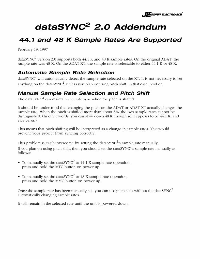
dataSYNC2 2.0 Addendum44.1 and 48 K Sample Rates Are Supported
February 19, 1997
dataSYNC2 version 2.0 supports both 44.1 K and 48 K sample rates. On the original ADAT, thesample rate was 48 K. On the ADAT XT, the sample rate is selectable to either 44.1 K or 48 K.
Automatic Sample Rate SelectiondataSYNC2 will automatically detect the sample rate selected on the XT. It is not necessary to setanything on the dataSYNC2, unless you plan on using pitch shift. In that case, read on.
Manual Sample Rate Selection and Pitch ShiftThe dataSYNC2 can maintain accurate sync when the pitch is shifted.
It should be understood that changing the pitch on the ADAT or ADAT XT actually changes thesample rate. When the pitch is shifted more than about 3%, the two sample rates cannot bedistinguished. (In other words, you can slow down 48 K enough so it appears to be 44.1 K, andvice versa.)
This means that pitch shifting will be interpreted as a change in sample rates. This wouldprevent your project from syncing correctly.
This problem is easily overcome by setting the dataSYNC2’s sample rate manually.If you plan on using pitch shift, then you should set the dataSYNC2’s sample rate manually asfollows:
• To manually set the dataSYNC2 to 44.1 K sample rate operation,press and hold the MTC button on power up.
• To manually set the dataSYNC2 to 48 K sample rate operation,press and hold the MMC button on power up.
Once the sample rate has been manually set, you can use pitch shift without the dataSYNC2
automatically changing sample rates.
It will remain in the selected rate until the unit is powered-down.