Embed Size (px)
Citation preview
Commissioning of World's LargestOxygen Blown Secondary Reformers
Technical difficulties and incidents associated with burner failure, refractory defects,and waste heat boiler fouling are described. Measures to identify and control problems
are discussed in detail, highlighting successes.
Gareth Shaw and Henry de WetMossgas, Mossel Bay, South Africa
Friedrich HohmannLurgi, Frankfurt, Germany
Introduction
The MOSSGAS synthetic oil from gas projectat Mossel Bay, a harbour town 390 km east ofCape Town, was undertaken in 1987 as astrategic project for South Africa. It is one offour synthetic oil installations in the countrybut is the only facility based on natural gas.The others are the Sasol oil-from-coal plants,respectively south-west and south-east ofJohannesburg.
i
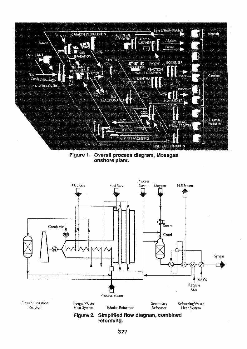
MOSSGAS ranks third in capacity, producing35 000 barrels/day, and is the most recent ofthe synthetic fuel projects. Natural gas as wellas associated light condensate is supplied to theonshore plant from a dedicated drilling andproduction platform some 85 kilometres (53miles) offshore. A process diagram of theoverall facility is shown in Figure 1.
The entire project, including the offshoreplatform and onshore production facility,represents a major achievement for the SouthAfrican engineering and management sector.The commissioning of the onshore plant inparticular represented an excellentaccomplishment with first gas arriving onshoreon 31 March 1992 and full production beingachieved by the 2 January 1993.
This short commissioning phase was notwithout difficulties, including thoseexperienced in the Methane Reforming plant.Overcoming those difficulties whilemaintaining production was achieved throughsheer hard work by the MOSSGAS teamworking in close co-operation with theengineering contractor, LURGI.
315
The methane reformer plant
The Methane Reforming unit is made up of threeidentical trains using LURGFS CombinedReforming process (Figure 2). It supplies thefeed for the downstream SyntholFischer-Tropsch synthetic fuel plant operatedunder licence from Sasol (Pty) Ltd.
A relatively small Primary Reformer is followedby an oxygen blown Secondary Reformer,similar to that used in methanol plants. Half ofthe natural gas feedstock is fed directly to theinlet of the Secondary Reformer along with thePrimary Reformer effluent and a recycle streamfrom the downstream Synthol plant. Thiscombination allows overall steam-to-carbonratios of down to 1.4 to be used producingsyngas with a H2/CO ratios of about 2.8. Longterm operation has to date been able to sustain850 000 Nm3/hr (500 000 scfm) successfully,being about 103% of guaranteed capacity.
This plant represents LURGFS largest oxygenblown Secondary Reformer to date. The recyclestream from a Fischer-Tropsch synthesis ishowever an order-of-magnitude larger than thatof a methanol plant, which not only enlarges theSecondary Reformer significantly in comparisonwith the Primary Reformer but also increases thedemands on its control system.
In terms of mass flow the three MOSSGASreformers each represent a scale-up of 140%over and above LURGFS (and the world's)previous largest oxygen-blown SecondaryReformer operational in Sabah, Malaysia. Thepressure of the Fischer-Tropsch syngasgenerating scheme is substantially lower thanthat of a methanol plant, so that the physical sizescale-up factor for the burner of the SecondaryReformer was about 2 (diameter).
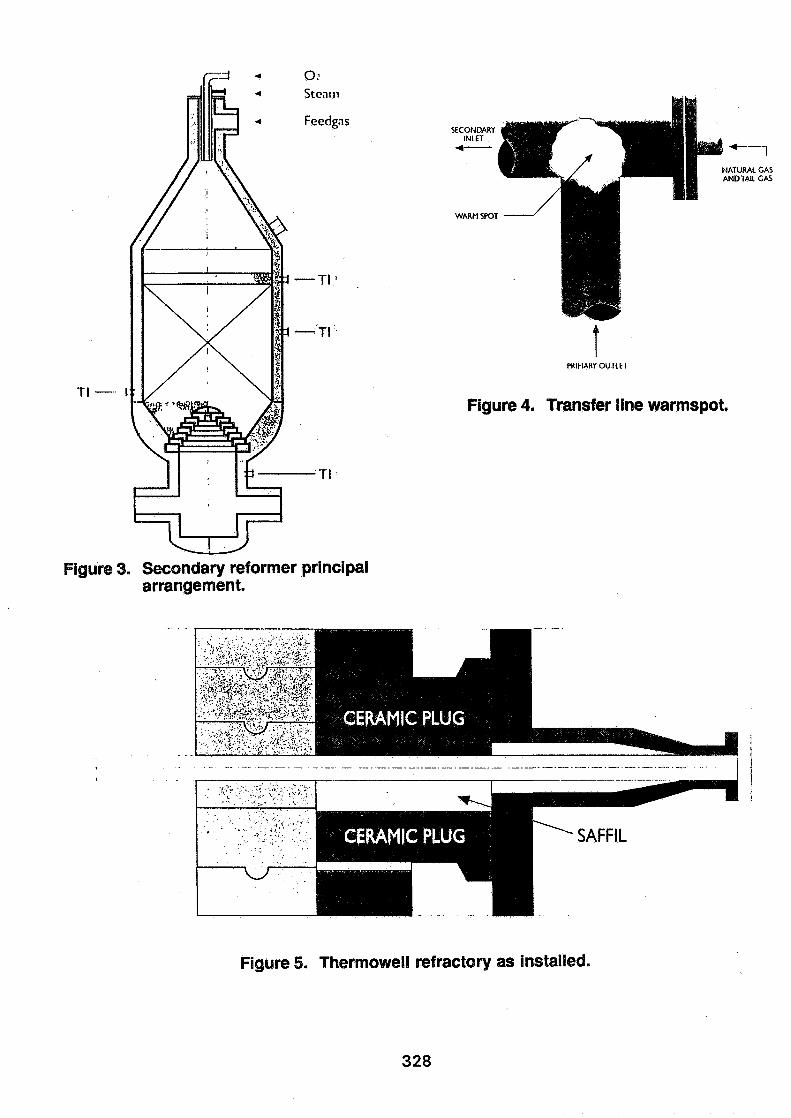
The Secondary Reformer (Figure 3) is a verticalrefractory-lined fixed-bed reactor with a conicalupper part. The catalyst bed only fills thereactor part way up the cylindrical shell. Aboveit is a free space in which the incoming gas,steam and oxygen react in a flame. The feedgas, that is to say the mix of Primary Reformer
effluent, the natural gas by-pass stream and theSynthol tail gas enters the burner from the sidevia the refractory lined transfer line. The otherreactants enter centrally through the single-topmounted burner. The catalyst bed is supportedabove the outlet by an inverted cone ofrefractory shapes. It is covered by a layer ofalumina lumps.
In view of the scale-up involved and on the basisof experience in the above-mentioned plant inSabah, specific attention was paid during thedesign phase to a number of issues, inparticular: '
» Secondary Reformer burner lifetime.
• Secondary Reformer refractory.
• Secondary Reformer shell temperaturemeasurement.
® Burner related process monitoring.
® Metal dusting of Waste Heat Boiler inletferrules and by- pass valve withconsequent gas phase carbon formation.
• Secondary Reformer Control andsafeguarding system, including sequenceof event recorder and two-out-of-threevoting for trip signals.
• Syngas compressor fouling.
316
Overview of commissioning
The reforming plant was commissionedmid-1992 achieving fall production by thebeginning of 1993. Detailed handover andcheck-out procedures were employed tostreamline ongoing construction, punching,handover and early commissioning activities.Assistance from LURGI and a local Sasolstart-up team allowed successful integration ofthe staggered commissioning and finalconstruction activities.
Operator training was initiated well in advancethrough other South African refineries andcomplimented with a locally developed DCSsimulator.
The Primary Reformers were classic LURGIpig-tail design and have given excellent servicefrom the very start. An interesting point tonotice is that under a technology-transferarrangement, these units contained the first-everSouth African reformer tubes. Despite initialdifficulties during the manufacture, productionof a total of 684 tubes was accomplished onschedule and in accordance with internationalquality standards. In fact the manufacturer hasalready succeeded in securing his first exportorders.
Many of the measures included in the specialattention areas mentioned above were sufficientlysuccessful that they were simply 'not an issue'during the start-up. These included the WasteHeat Boiler inlet ferrules, the sophisticatedcontrol and safeguarding system and the syngascompressor fouling. Other items on the listproved more difficult as described in this paper.
The initial start-up was delayed because of thenecessity to rebuild poorly erected refractories inthe secondary reformers. Mechanical problemsassociated with the scale-up of the secondaryreformer burners resulted in a shorted burnerlife than anticipated. Fouling of the waste heatboiler downstream of the secondary reformerwith sodium carbonate persisted over the wholestart-up period, forcing load restrictions andshut-downs for boiler-tube cleaning as well as
secondary damage due to metal dusting.
Each of the incidents brought about a number oftechnical efforts to identify and control theproblems. These are discussed below in moredetail.
Refractory
Refractory lining in the Secondary Reformercomprises three layers, two of which the hotface and the intermediate layer, are brick, withthe final insulating layer a castable refractoryanchored to the shell. The transfer line wasdelivered to site in sections, pre-lined withrefractory complete with the accompanyingmetal liner.
Transfer line
Initial concerns were encountered with thedrying out of the refractory of all three trains.Warm spots were identified with heat sensitivepaint on the tee piece in the transfer linebetween the Primary and Secondary Reformersduring dryout (Figure 4.)
Although the temperatures were still well withinthe transfer line design temperature of 350°C(662 °F) it was decided to make an inspection oncompletion of the dryout. No conclusive causefor the warm spots was revealed. Minorhairline cracks were evident but considered toonarrow to be the cause. One of the expansionjoints on the internal lining was welding up so asto provide a positive gas barrier and this wouldappear to have solved the problem.
Thermocouple entries
Feed was first introduced into the plant duringJuly 1992. Four days after the first start-up ofTrain 1, with the secondary reformer operatingat a load of about 90% a large hot spot appearedat one of the top bed thermocouple nozzles. Theloss of the temperature signal in the centralcontrol room, prompted inspection by theoperators who found the shell glowing in the
317
dark and beginning to distort. Shut-down wastoo late to prevent damage. The hot spot wasdetected by an experimental shell temperaturemonitoring system described below but was notreacted upon by operators because no alarms hadbeen implemented at that stage.
Immediate repair programs for Trains 2 and 3were organised and implemented once similarhot spots had begun appearing on one of the twoother trains. The cause for the hot spot at thethermocouple nozzle was put down to a gasby-pass from the thermocouple area to a gasbarrier about 3 metres (10 ft) lower, where itre-entered the interior of the reactor viaexpansion joints in the two inner brick layers.Both inlet and outlet to the by-pass could beattributed to incorrect installation of therefractory around the thermowell and of theexpansion joints. The problems identified wereas follows:
• The hole diameter through the hot facerefractory for the thermowell was toobig and not to design.
• Safil fibre (25 mm or 1 " thick) was usedto wrap around the thermowell insteadof masking tape. This bulkier, lessdense material produced a large voidaround the thermowell after casting ofthe thermowell refractory plug.
• As a result of the bulkier material,refractory anchors close to thethermowell had been removed duringrefractory installation, thus permitting agap to open up between the castable andthe shell.
• Expansion joints in the hot facerefractory and the second refractorylayer were in line with one anotherinstead of staggered. Furthermore theyboth passed through the thermocouplezone.
The two following diagrams reflect thedifferences between the installed refractory andthe design (Figs 5 and 6). Repairs were
conducted to all three trains as per the initialdesign. Thereafter there were no furtherproblems from this source.
Lower reactor
While Train 1 was being repaired, operationcontinued on Trains 2 and 3, as soon as thethermocouple area of the refractory had beenattended to. Unfortunately this had not been theonly installation problem with the refractory.Colour change in the heat sensitive paint beganindicating warm spots all over the barrel orlower section of the reactor. In the order of 25such warm spots were recorded per vessel.Checks with infrared detectors indicated thatmetal design materials had not been exceeded.Nonetheless it was decided to play safe andimplement air cooling of the shell. Air was usedin preference to steam to allow visual checks andcontinuation of infrared observation of any hotspot development. Operation of Trains 2 and 3with air cooling continued for about two monthsso as to maintain production while the Train 1reactor shell was being repaired. Refractoryrebuilding in Trains 2 and 3 permitted carefulevaluation of the cause of these warm spot in thelower reactor. The primary cause was put downto poor workmanship, with the followingdetailed reasons:
® The erection contractor had not placedany oil paper separation between theintermediate insulating fire brick (IFB)layer and the outer castable layer in thereformer. This caused bonding betweenthe two layers, which hindered thedifferential expansion between the twolayers. Cracks developed in both thelayers allowing gas by-passing behindthe castable. The following photographsshow the castable refractory with theIFB removed. (Figs 7 and 8).
• Void spaced in the castable refractorywere found due to poor compaction andwood shuttering since carbonized away.Interestingly some void spaces found didnot create warm spots on the shell.
318
Repair work on the reactors required unloadingof catalyst to allow for complete rebuilding ofthe refractory internals above the base. In thisprocess small design changes were incorporatedincluding a thicker castable layer, narrowerexpansion joints and Safil in the gaps. Re-use ofrefractory materials was accomplished whereever possible to reduce costs.
Both these problems caused considerable delayand additional expense - in one case actualdamage. The lesson learned here is that closeand continual monitoring of the refractoryinstallation by a specialist is essential duringinstallation. It is not a job for the generalerection supervisor and certainly not one onwhich either owner or contractor can afford toeconomize when setting up the contracts.
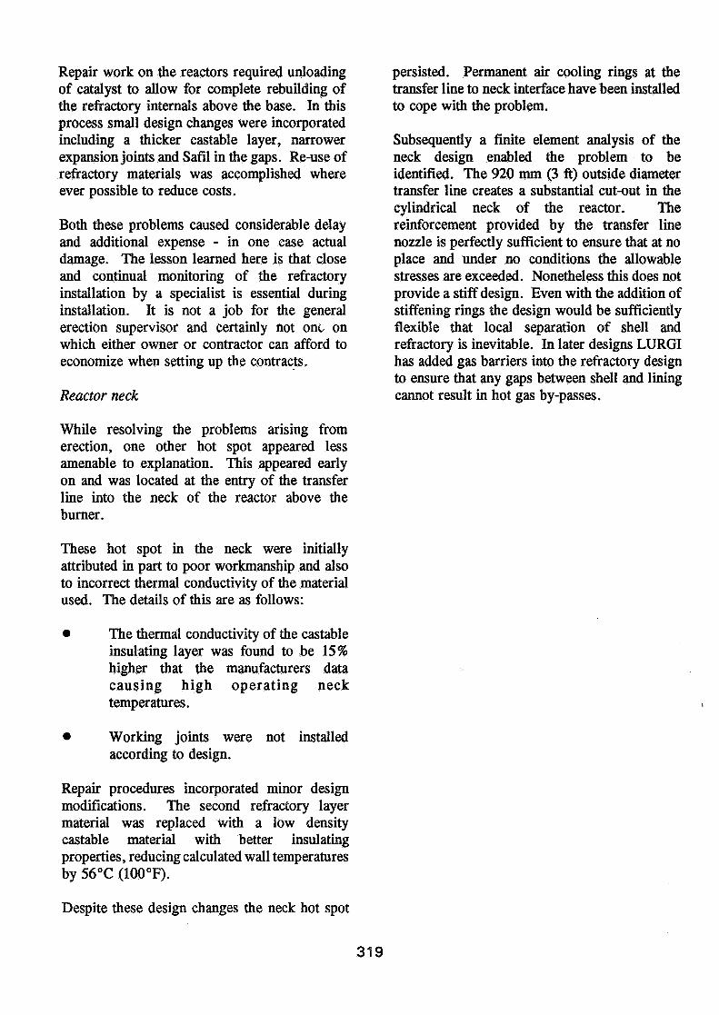
Reactor neck
While resolving the problems arising fromerection, one other hot spot appeared lessamenable to explanation. This appeared earlyon and was located at the entry of the transferline into the neck of the reactor above theburner.
These hot spot in the neck were initiallyattributed in part to poor workmanship and alsoto incorrect thermal conductivity of the materialused. The details of this are as follows:
• The thermal conductivity of the castableinsulating layer was found to be 15%higher that the manufacturers datacausing high operating necktemperatures.
• Working joints were not installedaccording to design.
Repair procedures incorporated minor designmodifications. The second refractory layermaterial was replaced with a low densitycastable material with better insulatingproperties, reducing calculated wall temperaturesby 56°C (100°F).
Despite these design changes the neck hot spot
persisted. Permanent air cooling rings at thetransfer line to neck interface have been installedto cope with the problem.
Subsequently a finite element analysis of theneck design enabled the problem to beidentified. The 920 mm (3 ft) outside diametertransfer line creates a substantial cut-out in thecylindrical neck of the reactor. Thereinforcement provided by the transfer linenozzle is perfectly sufficient to ensure that at noplace and under no conditions the allowablestresses are exceeded. Nonetheless this does notprovide a stiff design. Even with the addition ofstiffening rings the design would be sufficientlyflexible that local separation of shell andrefractory is inevitable. In later designs LURGIhas added gas barriers into the refractory designto ensure that any gaps between shell and liningcannot result in hot gas by-passes.
319
The Secondary Reformer Burner
Burner performance
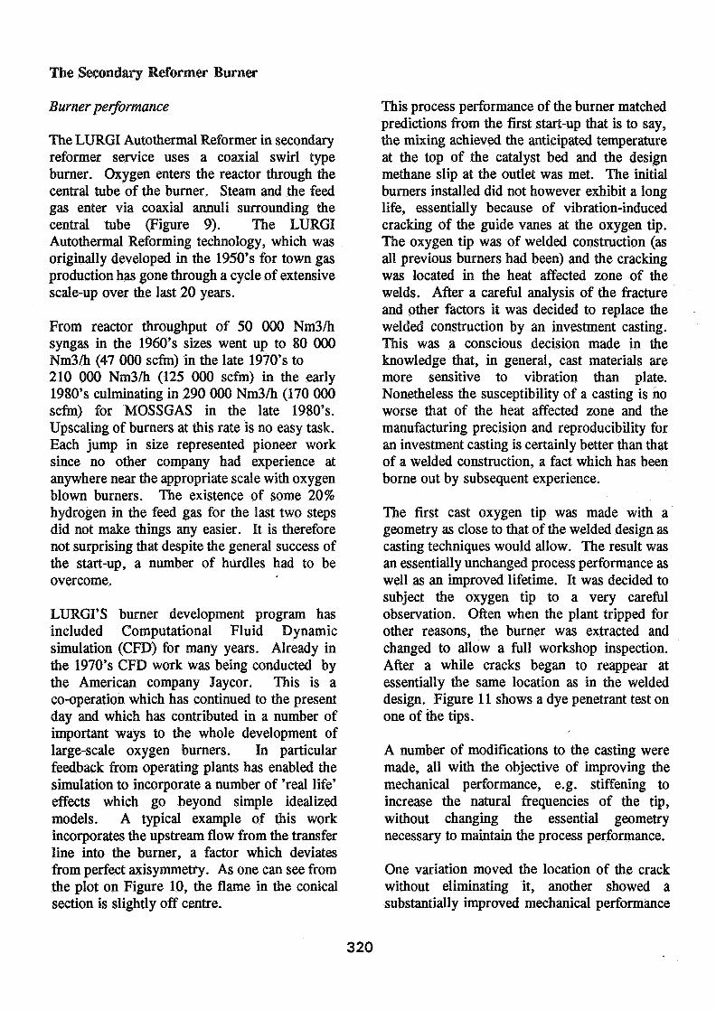
The LURGI Autothermal Reformer in secondaryreformer service uses a coaxial swirl typeburner. Oxygen enters the reactor through thecentral tube of the burner. Steam and the feedgas enter via coaxial annuli surrounding thecentral tube (Figure 9). The LURGIAutothermal Reforming technology, which wasoriginally developed in the 1950's for town gasproduction has gone through a cycle of extensivescale-up over the last 20 years.
From reactor throughput of 50 000 Nm3/hsyngas in the 1960's sizes went up to 80 000Nm3/h (47 000 scfm) in the late 1970's to210 000 Nm3/h (125 000 scfm) in the early1980's culminating in 290 000 Nm3/h (170 000scfm) for MOSSGAS in the late 1980's.Upscaling of burners at this rate is no easy task.Each jump in size represented pioneer worksince no other company had experience atanywhere near the appropriate scale with oxygenblown burners. The existence of some 20%hydrogen in the feed gas for the last two stepsdid not make things any easier. It is thereforenot surprising that despite the general success ofthe start-up, a number of hurdles had to beovercome.
LURGI'S burner development program hasincluded Computational Fluid Dynamicsimulation (CFD) for many years. Already inthe 1970's CFD work was being conducted bythe American company Jay cor. This is aco-operation which has continued to the presentday and which has contributed in a number ofimportant ways to the whole development oflarge-scale oxygen burners. In particularfeedback from operating plants has enabled thesimulation to incorporate a number of 'real life'effects which go beyond simple idealizedmodels. A typical example of this workincorporates the upstream flow from the transferline into the burner, a factor which deviatesfrom perfect axisymmetry. As one can see fromthe plot on Figure 10, the flame in the conicalsection is slightly off centre.
This process performance of the burner matchedpredictions from the first start-up that is to say,the mixing achieved the anticipated temperatureat the top of the catalyst bed and the designmethane slip at the outlet was met. The initialburners installed did not however exhibit a longlife, essentially because of vibration-inducedcracking of the guide vanes at the oxygen tip.The oxygen tip was of welded construction (asall previous burners had been) and the crackingwas located in the heat affected zone of thewelds. After a careful analysis of the fractureand other factors it was decided to replace thewelded construction by an investment casting.This was a conscious decision made in theknowledge that, in general, cast materials aremore sensitive to vibration than plate.Nonetheless the susceptibility of a casting is noworse that of the heat affected zone and themanufacturing precision and reproducibility foran investment casting is certainly better than thatof a welded construction, a fact which has beenborne out by subsequent experience.
The first cast oxygen tip was made with ageometry as close to that of the welded design ascasting techniques would allow. The result wasan essentially unchanged process performance aswell as an improved lifetime. It was decided tosubject the oxygen tip to a very carefulobservation. Often when the plant tripped forother reasons, the burner was extracted andchanged to allow a full workshop inspection.After a while cracks began to reappear atessentially the same location as in the weldeddesign. Figure 11 shows a dye penetrant test onone of the tips.
A number of modifications to the casting weremade, all with the objective of improving themechanical performance, e.g. stiffening toincrease the natural frequencies of the tip,without changing the essential geometrynecessary to maintain the process performance.
One variation moved the location of the crackwithout eliminating it, another showed asubstantially improved mechanical performance
320
but at the expense of increasing the catalyst topbed temperature beyond the set limit. Despite afairly rigid routine of inspection for the oxygentips, they have to date not actually caused asingle plant trip. The tips now in operation areimproved in mechanical performance withoutany process penalty.
The cracking of the guide vanes is clearly aresult of scale-up. This has been confirmed byretrospective analysis and comparison witholder, smaller designs. Considerable success hasbeen achieved in eliminating this problem.Nonetheless MOSSGAS and LURGI have anongoing program with the intention of achievingfurther improved performance.
Burner vibration monitoring
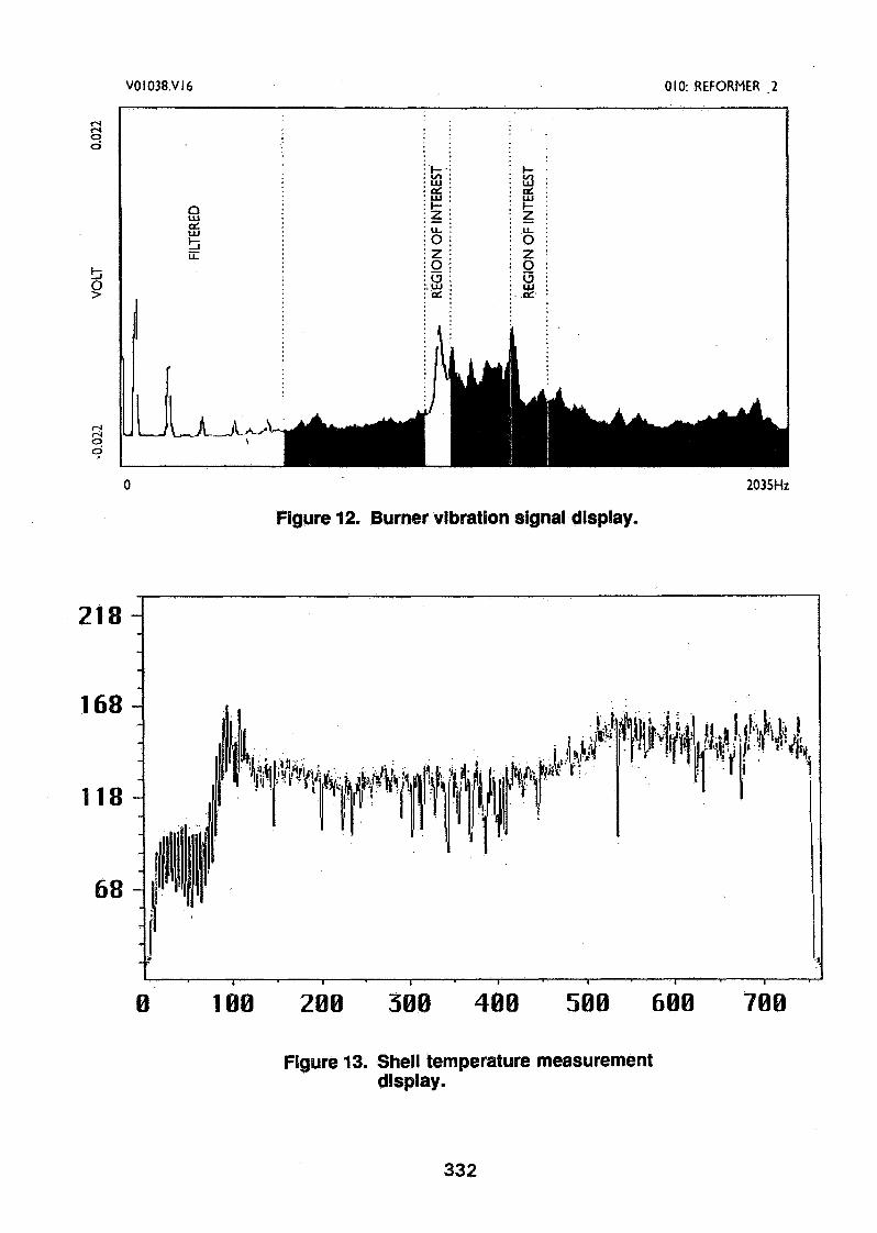
An integral part of this program is theinstallation of on-line burner vibrationmonitoring. After consultation with theUniversity of Cape Town, workshop and planttrials showed that the vibration of particularcomponents in the burner could be monitoredon-line. Conventional vibration monitoringequipment used for rotating machinery wasfound to be unsuitable. Equipment used formonitoring and analysing vibration changes ofnuclear reactors was set up to monitor thevibration signals from the three SecondaryReformer burners. The system monitors severalpredetermined regions of interest for changes invibration frequency and amplitude. Monitoringis based on the assumption that cracks in burnercomponents will drop natural vibrationfrequencies. A gradual drop in specificvibration frequencies would signal crackpropagation. The signal would then be used todetermine when the burner needs to be replaced.A typical trace of burner vibration signals withthe particular regions of interest highlighted, isshown in Figure 12.
Improvement of the oxygen tips has meant thatsince installation of the vibration monitoringequipment no further cracking of the tips hasoccurred so that the effectiveness of the systemstill has to be proved. Results to date havehowever shown that it is capable of detecting
changes in combustion-related vibration on loadchange in the Secondary Reformer.
Shell temperature measurement
During the design phase of the projectMOSSGAS and LURGI had reviewed a numberof systems to provide continuous shelltemperature measurement. Several systems wereconsidered including the conventional heatsensitive paint which was installed from thebeginning, infrared cameras, an electricalresistance wire system and a novel fibre optictemperature measurement system. Costs of thedifferent systems did affect the choice to someextent but the overriding factor affecting thedecision to go for the latter, as yet unprovensystem was its potential for differentiationbetween a small "hot" area and a large "warm"area, to localize the hot spot and to alarm theoperator to the existence of a hot spot. Othersystems could only fulfil part of theserequirements.
The U.K.-based suppliers, York, were able toprovide a unique optical fibre based systemcapable of measuring shell temperature overevery meter of fibre installed on the vessel,which totalled some 700 meters. The systeminstalled interfaces with a personal computer inthe control room providing the operator with anupdate of the shell temperatures every 2 to 4minutes. The operator is presented with ascreen shown in Figure 13.
The trends allow the operator to absorb the shelltemperature profile of three secondary reformersquickly. Alarms are set at 270°C (518°F) towarn the operator and provide a table of thehigh temperatures and their location on the shell.A second alarm at 350°C (662°F) is providedupon which the operator would trip theSecondary Reformer.
A limitation to the system was realised soonafter the order had been placed. The spatialresolution of 1 meter would not detect typicallysmall hot spots. To overcome this, Yorkprovided additional software designed to processincoming data for characteristic signs of small
321

hot spots. The software is designed to becapable of detecting down to a 300 mm (12")hot spot at 350°C (662 °F). The use of softwareto overcome the spatial resolution has proventroublesome as it is difficult to calibrate withnecessary accuracy.
Initial plant trials were conducted with roughly1 000 meters (3 280 ft)of fibre (in woven sleeve)taped to the vessel with polyamide tape. Thefibre was laid out vertically to start with, butsharp temperature gradients presented processingproblems. The fibre layout was changed tocircle the reactor and fitted into a steel sheathfor protection. After these preliminary trialsfixing to the shell was improved by using aceramic based cement which has recently beensuccessfully replaced by heat conductive cementof the type used for steam tracing. Despite thesteel protective sheath the fibre has been brokenby falling objects and scaffold piles.
Repair has been managed on-line but increasesin fibre background noise associated with therepairs is forcing better repair procedures to beconsidered.
Developments currently underway are to shortenthe update time by providing more machines andto increase the reliability of the hot spotdetection and temperature estimation. Withacceptable reliability the optical fibre system willbe connected directly to the BSD and will shutthe Secondary Reformer down on high shelltemperature. This represents the firstapplication of optic fibre technology for shelltemperature monitoring. This is a promisingsystem but does still have problems with smallhot spot detection software during start-up andwhen operating close to alarm levels.MOSSGAS and York are currently workingtogether to iron these problems out. Use of thissystem is recommended where shell operatingtemperatures are at least 150°C (270°F) belowdesign or trip levels. This novel hot spotdetection system does not yet have the capabilityof working on smaller operating margins.
322
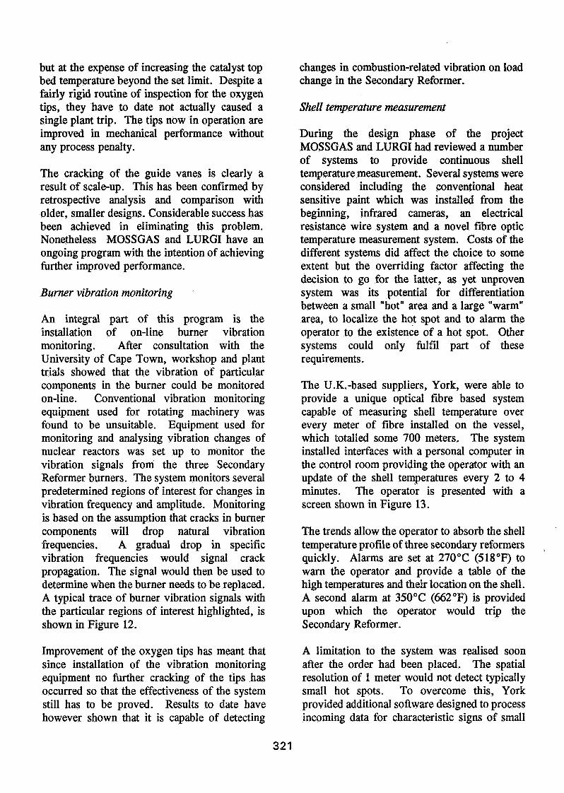
Sodium ingress
A number of phenomena appeared during thestart-up as a result of sodium ingress into theplant. The sodium quantities entering the planthave now receded to the point that the problemis no longer of major importance, although adefinitive conclusion as to the source has notbeen reached. Nonetheless the results of sodiumingress were clear enough and work iscontinuing on tracking down its origins.
Sodium is known to be detrimental to reformingplant performance. LURGI had experience withthe phenomenon of sodium carbonates foulingheat exchange surfaces in a number of otherplants with comparable gas composition, but inall cases the problem had been clearly attributedto sodium carry-over in the process steam.Another potential problem with high sodiumconcentrations in the hot face brick is thesoftening of the refractory caused by thestructural changes from a-alumina to b-alumina.This feature can also lower the melting point ofthe hot face refractory. These potential problemshad been addressed in the design by (a) limitingthe allowable sodium content of the processsteam to 10 ppb and (b) limiting the sodiumcontent in the refractory materials to 0.2 %.
Waste heat boiler fouling
Despite these precautions some time afterstart-up the waste Heat Boiler (WHB) by-passvalves were observed to be closing at a rate ofroughly 5% per day. Once the valve was fullyclosed, the outlet temperature of the WHBincreased up to the downstream exchangermechanical design temperature of 550°C(960°F) which is about 30°C (54°F) above theintended operating temperature. The only meansleft of controlling the temperature was byreducing load or oxygen flow to the SecondaryReformer Plant. Upsets, especially trips of thetrain were found to rectify the problem, i.e.removing the material fouling the WHB tubes.Regular shut-downs and steamouts were requiredto maintain heat transfer coefficients.
An aggravating side-effect associated with thehigher outlet temperatures was that this broughtthe metallic components of the WHB by-passvalve and part of the downstream heat exchangerinternals into the metal dusting range.By-products of metal dusting, carbon and metalcarbides contaminated the process condensateand plugging cage trim vent valves. Theprocess condensate filters originally provided incase it were necessary to remove metal dustingproducts from the inlet ferrules thereby gainedincreased importance and provided an immediatesolution to fouling by sodium carbonate.
An unplanned shut-down and inspection showedthe upstream tube sheet and tube inlets to beextremely clean, while the downstream tubes andtubesheet caked in a fine white powder. Thispowder was later identified as predominantly,sodium carbonate. The tubes were mechanicallycleaned by brushing but could probably havebeen suitably cleaned by blowing with air orsteam. The white powder was carefullyanalysed with the intention of tracing its origin.Physical examination of the powder under amicroscope is presented Figure 14.
Of particular note is the porous nature of thecompound explaining its insulating properties.The compound is also shown by the pictureabove to contain a number of differentsubstances in the matrix. Metallurgicalinspection of a tube removed from the WHBidentified a sodium layer along the entire lengthof the tube. This layer unlike that shown abovewas a hard dense coating, which gotprogressively thicker toward the hotter end. Itis assumed that this dense coating did not affectheat transfer as much as the low density powderaccumulating at the tube outlet side.
Discussions with ammonia plant operators,thanks to the Ammonia Symposium, confirmedthat the sodium fouling was fairly common.Selection of low sodium content refractorymaterials was recommended but this approachhad already been in place as described above.
323
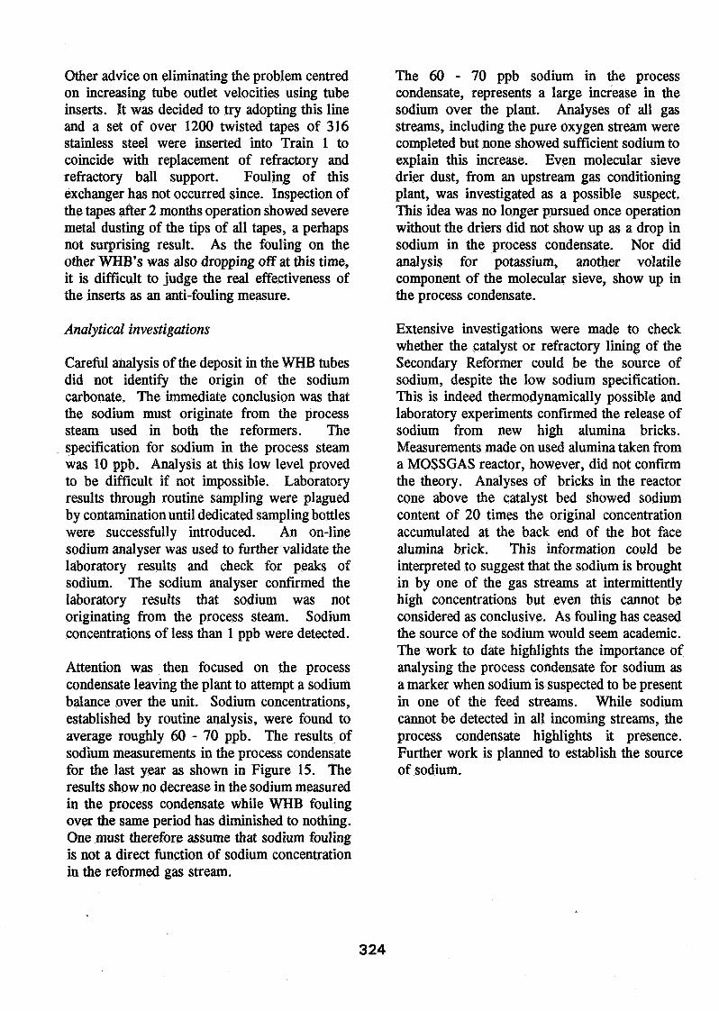
Other advice on eliminating the problem centredon increasing tube outlet velocities using tubeinserts. It was decided to try adopting this lineand a set of over 1200 twisted tapes of 316stainless steel were inserted into Train 1 tocoincide with replacement of refractory andrefractory ball support. Fouling of thisexchanger has not occurred since. Inspection ofthe tapes after 2 months operation showed severemetal dusting of the tips of all tapes, a perhapsnot surprising result. As the fouling on theother WHB's was also dropping off at this time,it is difficult to judge the real effectiveness ofthe inserts as an anti-fouling measure.
Analytical investigations
Careful analysis of the deposit in the WHB tubesdid not identify the origin of the sodiumcarbonate. The immediate conclusion was thatthe sodium must originate from the processsteam used in both the reformers. Thespecification for sodium in the process steamwas 10 ppb. Analysis at this low level provedto be difficult if not impossible. Laboratoryresults through routine sampling were plaguedby contamination until dedicated sampling bottleswere successfully introduced. An on-linesodium analyser was used to further validate thelaboratory results and check for peaks ofsodium. The sodium analyser confirmed thelaboratory results that sodium was notoriginating from the process steam. Sodiumconcentrations of less than 1 ppb were detected.
Attention was then focused on the processcondensate leaving the plant to attempt a sodiumbalance over the unit. Sodium concentrations,established by routine analysis, were found toaverage roughly 60-70 ppb. The results ofsodium measurements in the process condensatefor the last year as shown in Figure 15. Theresults show no decrease in the sodium measuredin the process condensate while WHB foulingover the same period has diminished to nothing.One must therefore assume that sodium foulingis not a direct function of sodium concentrationin the reformed gas stream.
The 6 0 - 7 0 ppb sodium in the processcondensate, represents a large increase in thesodium over the plant. Analyses of all gasstreams, including the pure oxygen stream werecompleted but none showed sufficient sodium toexplain this increase. Even molecular sievedrier dust, from an upstream gas conditioningplant, was investigated as a possible suspect.This idea was no longer pursued once operationwithout the driers did not show up as a drop insodium in the process condensate. Nor didanalysis for potassium, another volatilecomponent of the molecular sieve, show up inthe process condensate.
Extensive investigations were made to checkwhether the catalyst or refractory lining of theSecondary Reformer could be the source ofsodium, despite the low sodium specification.This is indeed thermodynamically possible andlaboratory experiments confirmed the release ofsodium from new high alumina bricks.Measurements made on used alumina taken froma MOSSGAS reactor, however, did not confirmthe theory. Analyses of bricks in the reactorcone above the catalyst bed showed sodiumcontent of 20 times the original concentrationaccumulated at the back end of the hot facealumina brick. This information could beinterpreted to suggest that the sodium is broughtin by one of the gas streams at intermittentlyhigh concentrations but even this cannot beconsidered as conclusive. As fouling has ceasedthe source of the sodium would seem academic.The work to date highlights the importance ofanalysing the process condensate for sodium asa marker when sodium is suspected to be presentin one of the feed streams. While sodiumcannot be detected in all incoming streams, theprocess condensate highlights it presence.Further work is planned to establish the sourceof sodium.
324
Metal dusting
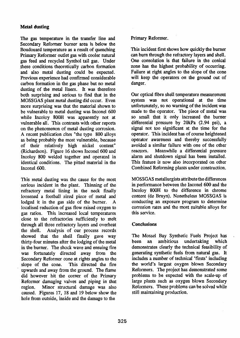
The gas temperature in the transfer line andSecondary Reformer burner area is below theBoudouard temperature as a result of quenchingPrimary Reformer outlet gas with cooler naturalgas feed and recycled Synthol tail gas. Underthese conditions theoretically carbon formationand also metal dusting could be expected.Previous experience had confirmed considerablecarbon formation in the gas phase but no metaldusting of the metal liners. It was thereforeboth surprising and serious to find that in theMOSSGAS plant metal dusting did occur. Evenmore surprising was that the material shown tobe vulnerable to metal dusting was Inconel 600while Incoloy 800H was apparently not atvulnerable all. This contrasts with other reportson the phenomenon of metal dusting corrosion.A recent publication cites "the type 800 alloysas being probably the most vulnerable, becauseof their relatively high nickel content"(Richardson). Figure 16 shows Inconel 600 andIncoloy 800 welded together and operated inidentical conditions. The pitted material in theInconel 600.
This metal dusting was the cause for the mostserious incident in the plant. Thinning of therefractory metal lining in the neck finallyloosened a football sized piece of metal andlodged it in the gas side of the burner. Alocalised reduction of gas flow raised oxygen togas ratios. This increased local temperaturesclose to the refractories sufficiently to meltthrough all three refractory layers and overheatthe shell. Analysis of our process recordsshowed that the shell finally gave waythirty-four minutes after the lodging of the metalin the burner. The shock wave and ensuing firewas fortunately directed away from theSecondary Reformer cone at rights angles to theslope of the cone. This directed the fireupwards and away from the ground. The flamedid however hit the corner of the PrimaryReformer damaging valves and piping in thatregion. Minor structural damage was alsocaused. Figures 17, 18 and 19 below show thehole from outside, inside and the damage to the
Primary Reformer.
This incident first shows how quickly the burnercan burn through the refractory layers and shell.One consolation is that failure in the conicalzone has the highest probability of occurring.Failure at right angles to the slope of the conewill keep the operators on the ground out ofdanger.
Our optical fibre shell temperature measurementsystem was not operational at the timeunfortunately, so no warning of the incident wasmade to the operator. The piece of metal wasso small that it only increased the burnerdifferential pressure by 20kPa (2.94 psi), asignal not too significant at the time for theoperator. This incident has of course heightenedoperator awareness and thereby successfullyavoided a similar failure with one of the otherreactors. Meanwhile a differential pressurealarm and shutdown signal has been installed.This feature is now also incorporated on otherCombined Reforming plants under construction.
MOSSGAS metallurgists attribute the differencesin performance between the Inconel 600 and theIncoloy 800H to the difference in chromecontent (de Bruyn). Nonetheless MOSSGAS isconducting an exposure program to determinecorrosion rates and the most suitable alloys forthis service.
Conclusions
The Mossel Bay Synthetic Fuels Project hasbeen an ambitious undertaking whichdemonstrates clearly the technical feasibility ofgenerating synthetic fuels from natural gas. Itincludes a number of technical 'firsts' includingthe world's largest oxygen blown SecondaryReformers. The project has demonstrated someproblems to be expected with the scale-up oflarge plants such as oxygen blown SecondaryReformers. These problems can be solved whilestill maintaining production.
325
References
T. van der Pas"Mossgas commissioned"Alternate Energy '93, Colorado Springs, April1993
Dr H.L. Roberts, R. de Bruyn andC. Higman"Syngas Production in the World's LargestInstallation at the Mossel Bay Synthetic FuelsProject", Eurogas '94, Trondheim, Norway,March 1994
J.A. Richardson"Boudouard carbon and metal dusting"Nitrogen, September/October 1993
R.G. St Leger" The Engineering Achievements of Mossgas"Chemical Processing S.A., April 1994
HJ. de Bruyn"Metal Dusting: Nickel Alloy Investigation"Mossgas Internal Report, June 1994
DISCUSSIONF.W. Hohmann, Lurgi: I would like to provide particular point where the metal dusting occurred?some additional information about metal dusting Shaw: Temperature would be 600 to 605°C. I willand Incoloy 800. Incoloy 800 is fully resistant, estimate gas composition.upstream of the secondary reformer where we have J. Korkhaus, BASF: Which welding materialsa gas that falls below the Boudouard equilibrium have been used for the weld you showed us?temperature of only 780°. It isn't resistant at all Hohmann: It's very simple. The weld also hasdownstream of the secondary reformer, where we been attacked, and the weld is Incoloy 625.have a Boudouard equilibrium temperature, if you Sometimes it's really surprising,take it as a measure for the severity of corrosion of Korkhaus: Obviously, there are only very specific835°. We have experienced from similar other solutions. In the superheater of our Antwerpplants, or from another plant where we experienced ammonia plant, Alloy 800 H suffered metal dust-failure, corrosion rates of Incoloy 800 downstream ing and the new bundle made of Alloy 600 did not.of the secondary reformer up to 50 mm per year. Shaw: That emphasizes while we don't knowThere is really a limited application. Incidentally,nobody knows exactly why that Incoloy 600 is farmore attacked than Incoloy 800, but only for thisspecial application. This can't be extended to othergases, other operating conditions, or anything.R.J.N. Gommans, DSM Services: Can you tell usthe temperature and the gas composition at this
enough about metal dusting, a program should beput in place before you start up.K. Nassauer, Deutsche Babcock-Borsig: Have youtested any other kind of material like 601 or 625regarding metal dusting ?Shaw: We have a running program right now cov-ering a number of materials including at least 601.
Henry de Wet Gareth Shaw
326
CATALYST PRpARATIQN ALdOHOLRECOVERY«f ALKY &
• • ' ' IfBUTAMERI
Lieht & Heavy Alcohols
IMG PLANT
'•Gas... ..• Condensât«'
Net RECOVERY
METHANE'RËFÇJRMIR;
Butylène." JSOMERISER
, isöperatej
fKPREATER
Figure 1. Overall process diagram, Mossgasonsliore plant.
Nnt.Gns Fuel GnsProcessStenm Oxygen H.P.Stenm
fr
DcsulphurizntionReactor
Fluegas WasteHeat System
Process Steam
Tubular ReformerSecondaryReformer
RecycleGas
Reforming WasteHeat System
Figure 2. Simplified flowreforming.
327
Tl — r
Feedgns
Tl
Tl
Figure 3. Secondary reformer principalarrangement.
WARM SPOT
NATURAL GASAND TAIL GAS
PRIMARY OU Tit I
Figure 4. Transfer line warmspot.
Figure 5. Thermo we n refractory as installed.
328
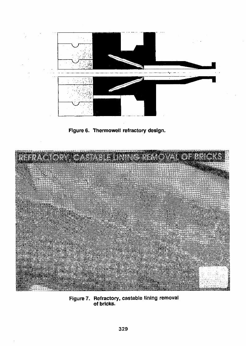
Figure 6. ThermoweU refractory design.
Figure 7. Refractory, eastable lining removalof bricks.
329
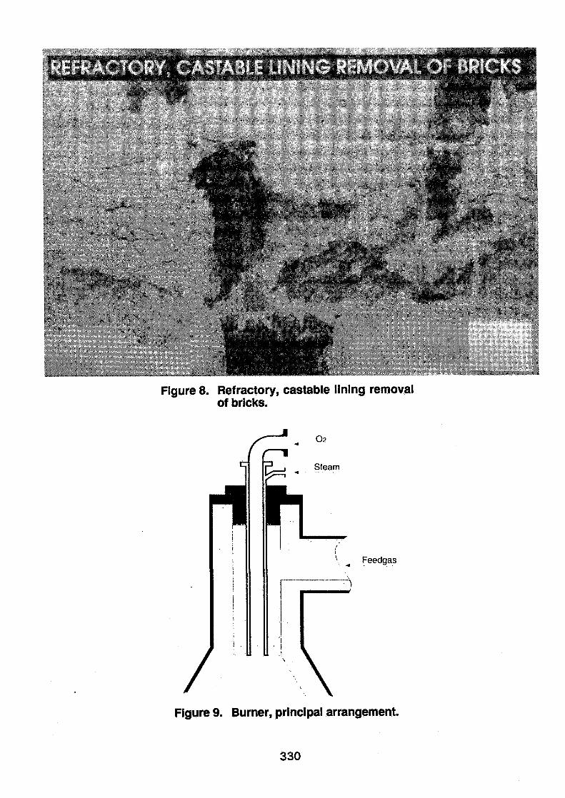
Figure 8. Refractory, castable lining removalof bricks.
Feedgas
Figure 9. Burner, principal arrangement.
330
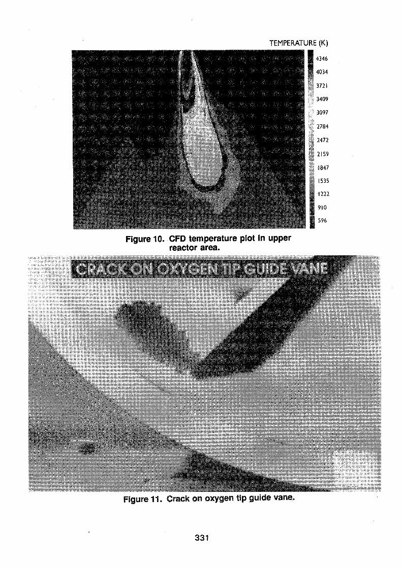
Figure 10. CFD temperature plot In upperreactor area.
Figure 11. Crack on oxygen tip guide vane.
331
VOI038.VI6 OIO: REFORMER 2
r-4r*po
b9
2035Hz
Figure 12. Burner vibration signal display.
218
168
118
68
0 100 200 300 400 500 600 700
Figure 13. Shell temperature measurementdisplay.
332
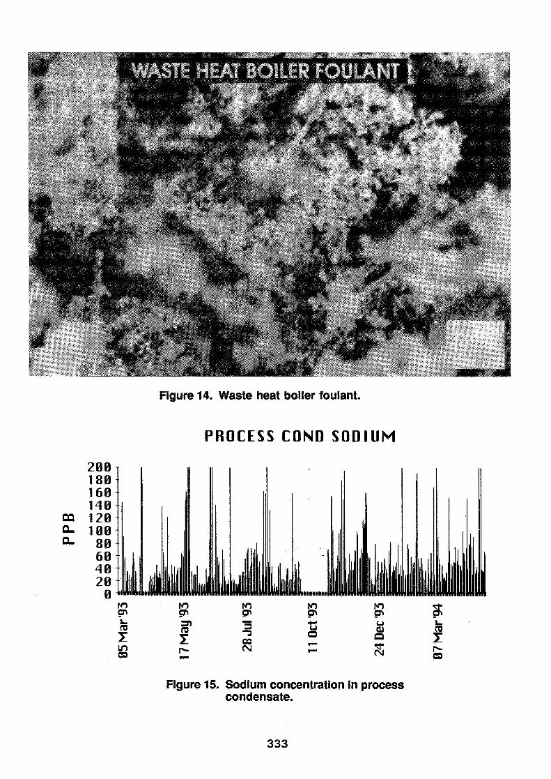
Figure 14. Waste heat boiler foulant.
PROCESS COND SODIUM
QQQ.Q.
Figure 15. Sodium concentration in processcondensate.
333
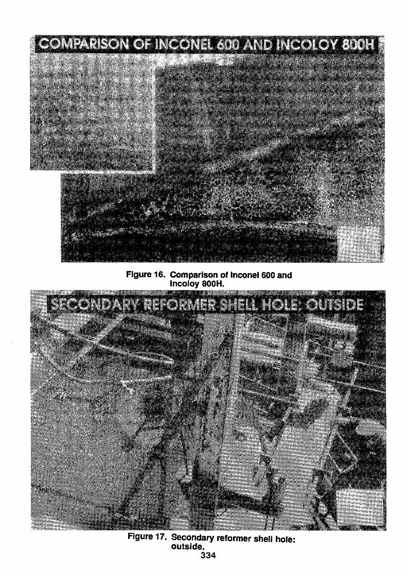
Figure 16. Comparison of Inconel 600 andIncoioy 800H.
Figure 17. Secondary reformer shell hole:outside.
334
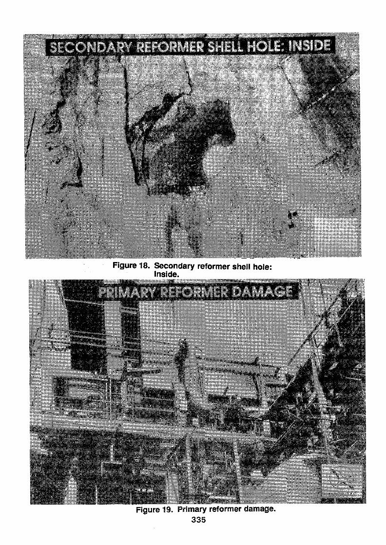
Figure 18. Secondary reformer shell hole:inside.
Figure 19. Primary reformer damage.335