Embed Size (px)
Citation preview
AD-A244 180
DTICSm~ EILECTE:JAMt 07? 1992'
dhj CI ha een approvedt'r ~ CO pihj.r!1 e rdsole its
DEPAR TMENT OF THE AIR FORCEAIR UNIVERSITY
AIR FORCE INSTITUTE OF TECHNOLOGY
Wright-Patterson Air Force Base, Ohici
0 C)9

AFIT/GCS/ENG/91D-08
JAN 0 7 1992 al
Design and Implementation of a Graphical User Interfaceand Database Management System for the Saber Wargame
THESIS
Andrew HortonCaptain, USAF
AFIT/GCS/ENG/91D-08
Approved for public release; distribution unlimited
AFIT/GCS/ENG/91D-08
Design and Implementation of a Graphical User Interface and Database
Management System for the Saber Wargame
THESIS
Presented to the Faculty of the School of Engineering
of the Air Force Institute of Technology
Air University
In Partial Fulfillment of the
Requirements for the Degree of
Master of Science (Computer Science) Acces1
........................... .....'..................
Andrew Horton, B.S.
Captain, USAF
i.~
December, 1991
Approved for public release; distribution unlimited
Preface
The goal of this thesis was to design and implement a graphical user interface and
database management system for the Saber theater-level wargame. It is a continuation of
two previous thesis efforts to develop an integrated wargame to teach tactical employment
concepts to future leaders in the United States armed forces.
This thesis documents the methodology, efforts and sofware products produced that
went into achieving these goals. My sincere hope is that this work proves beneficial to the
Air Force Wargaming Center and the United States Air Force in general.
I thank the Lord Jesus Christ for his grace, love, and countless undeserved blessings.
I am deeply indebted to Major Mark Roth, my thesis advisor, for his patience, direction,
and invaluable assistance during the development of this thesis effort. I wish to thank
the additional members of my thesis committee, Dr. Henry Potoczny and Major Michael
Garrambone, for their wisdom and assistance. Special recognition is given to my thesis
partners, Captain Gary Klabunde and Captain Christine Sherry, for their patience and
effort spent in the completion of this project. I cannot say thank you enough to Arlene
and Qiana Bryant for their undying love, selflessness and inspiration. I also thank the
entire class of GCS-91D, especially Dennis Rumbley and Tim Jacobs, for their friendship.
I must acknowledge my cat, Garfield, who kept me company on the many late evenings
I spent burning the midnight oil. Finally, extra-special thanks goes to Yulaunda Abram,
my future wife, for her unwavering support, prayers, and understanding during throughout
the course of this project.
Andrew Horton
Table of Contents
Page
Preface....... .... . ..... . . .... .. .. .. .. .. .. .. .. .. .. .. .
Table of Contents...... ..... . . .. ... .. .. .. .. .. .. .. .. .. .. . ....
List of Figures. .. .. .. .... ... ... ... ... ... ... ... ... ..... vii
List of Tables .. .. .. .. ... ... ... ... ... ... .... ... ... ..... ix
Abstract .. .. .. .. ... ... ... ... ... ... ... ... ... .... . ...
1. Introduction .. .. .. .. ... ... ... ... ... ... ... ... ... ....
1.1 Overview .. .. .. ... ... ... ... ... ... ... ... ... 1
1.2 Background .. .. .. .. ... ... ... ... ... ... ....... 1
1.3 Problem Statement. .. .. .. .. ... ... ... ... ... .... 3
1.4 Research Objectives and Constraints. .. .. .. .. ... ... ... 3
1.5 Methodology. .. .. .. ... ... ... ... ... ... ....... 4
1.6 Scope and Limitations .. .. .. .. ... ... ... ... ... ... 5
1.7 Materials and Equipment .. .. .. ... ... ... ... ... ... 6
1.8 Outline of Document. .. .. .. .. ... ... ... ... ....... 6
II. Summary of Current Knowledge. .. .. .. .... ... ..... ... ... 7
2.1 Overview .. .. .. ... ... ... ... ... ... ... ... ... 7
2.2 User Interface Issues .. .. .. .. ... ... ... ... ... .... 7
2.2.1 Background of User Interfaces and Their Design .. .. ... 7
2.2.2 User Interface Design Objectives .. .. .. .. .. .. .... 7
2.3 The X Window System. .. ... ... .... ... ... ..... 10
2.4 OSF/Motif .. .. .. .. ... ... ... .... ... ... ..... 10
iii
Page
2.5 Saber Database Management ...... .................... 11
2.5.1 Database Management Concerns ................... 11
2.5.2 The ORACLE Database Management System ...... ... 12
2.6 User Interface Applications of Existing Wargames ........... 12
2.6.1 Theater Analysis Model AirLand Campaign Model. . . 13
2.6.2 Theater War Exercise ......................... 14
2.7 Database Management Systems and Design ................ 15
2.8 Top Down Database Design Methodology ................. 15
2.9 Relational Database Design Considerations ................ 17
2.10 Summary ........ ............................... 18
III. Saber Database Implementation ........... . .................... 20
3.1 Saber Top Down Design ...... ....................... 20
3.2 Reducing Entity-Relationship Diagram to Relations .......... 22
3.3 SABER Database Implementation ..................... 29
3.3.1 The 11ex, Airhex, and Travel Relations .............. 29
3.3.2 The Assets Entity and Asset Visibility ........... ... 33
3.3.3 Hexside Assets Relation ......................... 35
3.3.4 Roads, Railroads, and Pipelines .................. 35
3.3.5 FEBA, Borders, Coasts, and Rivers ................ 36
3.3.6 The City Relation ............................ 37
3.3.7 The Weather and Cycle Relations ................. 37
3.3.8 The Airbase and Depot Relations ................. 39
3.3.9 Weapons and the Weapons-Class Relation ........... 40
3.3.10 Aircraft Type .............................. 41
3.3.11 Runways, Airbase Aircraft, Airbase Weapons, and Cross
Servicing .................................. 41
3.3.12 Aircraft Missions, Aircraft Packages, Targets ....... ... 44
iv
Page
3.3.13 Target Hardness ............................ 47
3.3.14 Preferred Weapons Loads ....................... 48
3.3.15 The Staging Base Relation ..................... 49
3.3.16 Land Units ................................ 49
3.3.17 Land Unit Movement .......................... 52
3.3.18 Supply Trains and Supply Movement ............... 52
3.3.19 Satellites .................................. 53
3.4 Database Uploading and Downloading ................... 54
3.4.1 ASCII Flat File Format ......................... 54
3.4.2 Downloading Oracle Relations to ASCII ............ 55
3.4.3 Uploading ASCII Files into Oracle with SQL*Loader. 56
3.5 Database Verification ....... ........................ 58
3.6 Summary ........ ............................... 59
IV. Saber User Interface Implementation ............................ 61
4.1 Overview ........ ............................... 61
4.2 Methodology ........ ............................. 62
4.3 Saber User Interface Design .......................... 65
4.3.1 Data Input ................................ 65
4.3.2 Help Facilities .............................. 65
4.3.3 Feedback, Dialogue, and Warning Messages ........ ... 66
4.3.4 Forgiveness ................................ 67
4.3.5 Error Prevention ............................ 68
4.4 Saber User Interface Implementation - User Input ........... 68
4.4.1 Aircraft Movement .......................... 68
4.4.2 Land Unit Instructions ........................ 72
4.4.3 Transportation of Supplies ..................... 73
4.4.4 Aircraft Mission Input ........................ 73
v
Page
4.5 X Window Implementation.......................... 76
4.6 Summary. .. .. .. ... ... ... .... ... ... ... .... 78
V. Summary and Conclusions. .. .. .. .. ... ... .... ... ... ...... 80
5.1 Summary of Work. .. .. .. ... ... .... ... ... ...... 80
5.2 Recommendations for Future Work .. .. .. .. ... ... ..... 81
5.3 Conclusion .. .. .. ... ... ... ... .... ... ... .... 81
Appendix A. Saber Relation Tables Dictionary. .. .. ... ... ... ..... 82
A.1 Dictionary Description. .. .. .. .. ... ... ... .... .... 82
A.2 Relation Table Dictionary. .. .. .. .. .... ... ... ...... 82
Appendix B. Saber Data Attributes Dictionary .. .. .. ... ... ... .... 103
B.1 Dictionary Description .. .. .. .. ... ... ... ... ... .. 103
B.2 Saber Data Attributes. .. .. .. ... ... ... ... ... .... 103
Appendix C. Saber Upload Flat Files to Oracle Program .. .. .. .. .. .... 131
Appendix D. Saber User Interface Input Screens. .. .. .. .. ... ... ... 134
Bibliography .. .. .. ... ... ... ... .... ... ... ... ... ... .... 137
Vita .. .. .. ... ... ... ... ... ... ... ... ... ... .... ... .. 140
vi
List of Figures
Figure Page
1. Typical Combat Model ....... ............................. 5
2. Different Stages of Normal Forms ...... ....................... 17
3. Saber Database ER Diagram (Part 1) ........................... 23
4. Saber Database ER Diagram (Part 2) ........................... 24
5. Saber Database ER Diagram (Part 3) ........................... 25
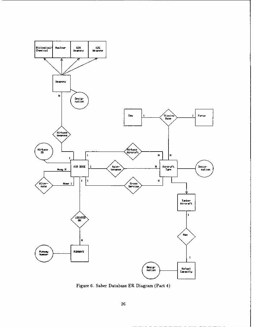
6. Saber Database ER Diagram (Part 4) ........................... 26
7. Saber Database ER Diagram (Part 5) ........................... 27
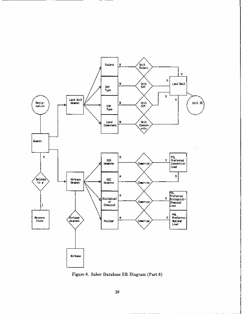
8. Saber Database ER Diagram (Part 6) ........................... 28
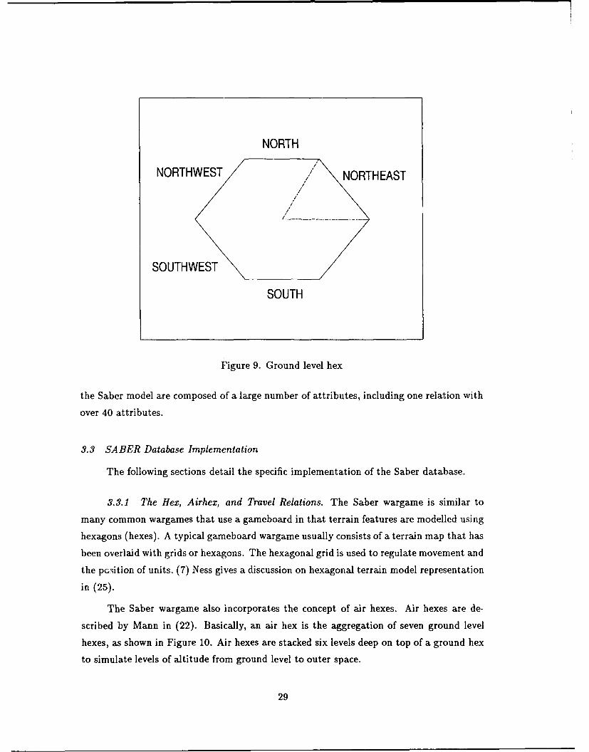
9. Ground level hex ........ ................................. 29
10. Airhex Grid ......... ................................... 30
11. Saber Ground Level Hex Grid System .......................... 30
12. Neighbor ID ......... ................................... 31
13. Center Hex ......... .................................... 32
14. Hex Assets ......... .................................... 34
15. Land Unit Hierarchy Chart ....... ........................... 51
16. SQL*Plus Download Code for A2AWeapons Relation ................ 56
17. Sample Control File for A2AWeapons Relation ................... 57
18. Sample User Input Icons ........ ............................ 63
19. User Interface Template .................................... 64
20. Valid Entries for Airbase Identification and Aircraft Designation ....... .. 67
21. Sample Warning Dialogue Window ............................. 68
22. Aircraft Movement Data Entry Template ........................ 69
23. Airbase Listing Selection ........ ............................ 70
24. Airbase Graphical Selection .................................. 71
25. Aircraft Mission Selection List ....... ......................... 72
vii
Figure Page
26. Airhex Selection ........ ................................. 74
27. Aircraft Package and Targets Interface Screen ..... ................ 75
28. Motif Widgets Used in the Saber GUI .......................... 77
29. Aircraft Movement Data Entry Template ..... ................... 134
30. Aircraft Mission Interface Screen ...... ........................ 135
31. Aircraft Package and Targets Interface Screen ..... ................ 135
32. Land Unit Movement Interface Screen .......................... 136
33. Supply Movement Interface Screen ............................ 136
viii
List of Tables
Table Page
1. Samples of the 162 data display guidelines from Smith and Mosier ..... 9
2. Saber Database Objects .................................... 20
3. Object Specializations ........ .............................. 21
4. Object Generalizations ........ ............................. 21
5. HexsideAssets Relation .................................... 35
6. The Roads Relation ........ ............................... 36
7. The City Relation ........ ................................ 37
8. The Weather Relation ........ .............................. 38
9. The Cycle Relation ........ ............................... 39
10. Weapon Specialization Relation Names ...... .................... 40
11. Sample Weapons-Class Relation ....... ........................ 41
12. The AirbaseAircraft and Airbase-Weapons Relations ................ 42
13. The Cross-Service Relation ....... ........................... 42
14. The Runways Relation ........ ............................. 43
15. The AlternateAirbase Relation ....... ........................ 43
16. Saber Mission Matrix ........ .............................. 44
17. The Aircraft_-Mission, Aircraft_-Package, and Targets Relations .......... 45
18. The ValidAC_-Missions Relation ....... ........................ 46
19. The Hardness Relation ........ ............................. 47
20. Weapons-Load Relation ....... ............................. 47
21. PCL - Preferred Conventional Load Relation ..................... 49
22. The Staging-Base Relation ....... ........................... 49
23. Unit-Supports Relation ........ ............................. 50
24. Subset of the Land Unit Relation ...... ....................... 51
25. Sample Move Relation ..................................... 52
ix
Table Page
26. Supply-Movement Relation .. .. .. ... ... ... ... ... ... ..... 53
27. A2A..Weapons Relation and Attribute Format. .. .. ... ... ... .... 55
28. Surface- to- Surface Missile Relation .. .. .. .. ... ... ... ... ..... 59
x
', AFIT/GCS/ENG/91D-08
Abstract
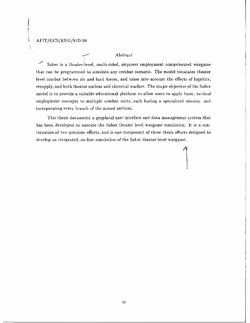
Saber is a theater'level, multi-sided, airpower employment computerized wargame
that can be programmed to simulate any combat scenario. The model simulates theater
level combat between air and land forces, and takes into account the effects of logistics,
resupply, and both theater nuclear and chemical warfare. The major objective of the Saber
model is to provide a suitable educational platform to allow users to apply basic, tactical
employment concepts to multiple combat units, each having a specialized missioil and
incorporating every branch of the armed services.
This thesis documents a graphical user interface and data management system that
has been developed to execute the Saber theater level wargame simulation. It is a con-
tinuation of two previous efforts, and is one component of three thesis efforts designed to
develop an integrated, on-line simulation of the SaLer theater-level wargame.
xi
Design and Implementation of a Graphical User Interface and Database
Management System for the Saber Wargame
I. Introduction
1.1 Overview
Saber is a theater-level, multi-sided, airpower employment computerized wargame
that can be programmed to simulate any combat scenario. The model simulates theater
level combat between air and land forces, and takes into account the effects of logistics,
resupply, and both theater nuclear and chemical warfare. The major objective of the
Saber model is to provide a suitable educational platform to allow users to apply basic,
tactical employment concepts to multiple combat units, each having a specialized mission,
and incorporating every branch of the armed services. (22) This thesis documents the
graphical user interface and data management system that has been developed to execute
the Saber theater level wargame simulation.
The Saber model was developed by Captain William F. Mann and Captain Mar-
lin A. Ness at the Air Force Institute of Technology for use by the Air Force Wargaming
Center at Maxwell AFB, Alabama (22). The game was originally designed to incorporate
current USAF and US Army doctrine into a new AirLand theater wargame.
The model currently supports both the land and air aspects of theater warfare, and
the model can be extended to incorporate naval operations as well. Air aspects that are
modelled include reconnaissance, close air support, interdiction, suppression of enemy air
defenses, combat air patrol, and many others (22). Fundamental land missions that are
simulated include, among others, exploitation, pursuit, and various offensive and defensive
combat movements and postures (25).
1.2 Background
The history of wargames is long. The need for accurate wargames is no secret, and
has been extensively documented. Several benefits of realistic computer war simulations
include:
" Provide training - Wargames are training platforms that can be used to instruct
future leaders in the art of conducting combat operations that encompass a wide va-
riety of scenarios. Lessons learned from mistakes made on a computerized battlefield
may eventually save lives on an actual battlefield.
" Save material and manpower - A computer simulation is less expensive to execute
than performing an actual theater-level war exercise using real people and equipment.
Resources that are used during actual training exercises are also saved. Furthermore,
exercise that include real people involve the inherent risk of injuries to personnel or
even loss of life.
" Repetition - A computer simulation allows users not only to recreate specific events,
but also to explore different outcomes that might occur if the players decide to do
things differently.
" Time compression - A battle scenario that spans several days or weeks can be sim-
ulated by a computer in a matter of hours.
Further information on the history, benefits, and importance of wargames can be found in
(7, 8, 22, 25).
In (25), Marlin Ness described the development of a theater level land combat model
that incorporated the latest land combat modeling theory, army operating procedures, and
tactical and strategic operations of units in the field. The model is a simulation of the
doctrinal planning and decision making operations that are conducted at the army group
level, providing credible land combat processes, unit movement and attrition, logistics, and
intelligence based on player inputs, airland unit interactions and terrain characteristics.
William Mann took the land battle model developed by Ness, redefined the ground
combat units, and integrated Air Force doctrine, producing a new model, known as Saber,
that incorporated both air and land battles. Saber introduced stochastic attrition between
aircraft, ground forces, and theater air defenses by joining together unclassified engineering
submodels to gain credible interactions between aggregated entities. The major compo-
nents of this new model are stochastic attrition, aircraft packages, logistics, intelligence,
and nuclear warfare. (22)
Both Mann and Ness dealt primarily with conceptual models of a wargame, concen-
trating on the playing pieces and the algorithms necessary for a realistic simulation. The
scopes of their theses did not contain the development of an appropriate data management
2
system or user interface for their models. However, they did provide guidelines and insight
into how additions to their models could be integrated into a complete package.
Mann defined four areas of player input necessary to implement the Saber theater
level wargame. These areas are aircraft beddown, transportation of supplies, instructions
to land units, and finally, aircraft and missile missions (22). Each of these areas of input
are addressed: in this thesis.
1.3 Problem Statement
Modern computerized wargames require a substantial amount of data to be input by
the players of the games. The large amount of data that is required as input to a wargame
can take a significant amount of time to be entered into a computer. Furthermore, for the
game to be as realistic and believable as possible, the instructions supplied to the wargame
should be in a format similar to the commands issued during actual armed conflicts. Not
only does a large volume of data need to be entered into a computer before a simulation
can begin, but the entered data also must be properly tracked and readily available for
manipulation. The problem addressed in this thesis is the input and storage of data
necessary for proper execution of the Saber theater level wargame.
1.4 Research Objectives and Constraints
After examining various alternatives, and considering the constraints set forth by
the sponsor of this thesis, it was determined that the input of data into the wargame
could be appropriately handled through the use of a graphical user interface. In addition,
it was determined that the management and manipulation of data for the Saber game
could best be handled through the use of a database management system. Therefore, the
purpose of this thesis effort is to document the design and implementation of a graphical
user interface and relational database management system for the Saber theater level
computerized wargame. The interface is capable of managing all data entered by the
players of the wargame, and the database management system has been designed to allow
fast and easy retrieval and manipulation of all data used in the wargame simulation.
The implementation constraints as set forth by the Air Force Wargaming Center
were:
1. The interface must allow fast, simple, and user-friendly input of information in a
format similar to the commands issued in war.
3
2. The user interface must be coded using the Open Systems Foundation (OSF) Motif
(27) toolkit in conjunction with the X Window System (39).
3. All input and wargame data must be stored in flat files that can be accessed by a
relational database.
4. The user interface and database implementation must execute on a Sun 386i and be
transportable to a Sun Sparc IIor compatible workstation.
1.5 Methodology
The major portion of this thesis effort was to implement a graphical user interface
and a database management system (DBMS) for the Saber theater level wargame. The
implementation followed these steps described below:
1. Determine all player inputs and database entities necessary to implement the wargame
simulation. This was accomplished by reviewing suggested player inputs listed in
previous theses (22, 25), and inputs requested in Air Force Wargaming Center re-
quirement documents (10). Reviews were accomplished by the Saber implementation
team, which consisted of Major Mark Roth, Major Michael Garrambone, Captain
Andrew Horton, Captain Gary Klabunde, and Captain Christine Sherry.
2. Classify related inputs by categories. This was also accomplished by iterative reviews
of the Saber implementation team.
3. Construct menu systems that allow input by category. The menu system was con-
structed to allow related information to be input as a unit.
4. Construct appropriate entity-relationship (ER) diagrams. ER diagrams were con-
structed to map the relationships between the various entities and attributes used in
the Saber model, and to display the overall logical structure of the database. The
ER models represent certain constraints to which the contents of the Saber database
must conform to. One such constraint is mapping cardinalities which express the
number of entities to which another entity can be associated via a relationship set.
(19)
5. Convert ER diagrams to database relations. For each entity set and for each rela-
tionship set in the Saber database, a unique relation table was created which was
assigned the name of the corresponding entity set or relationship set. The attributes
for each entity correspond to the column names of the relation table. (19)
4
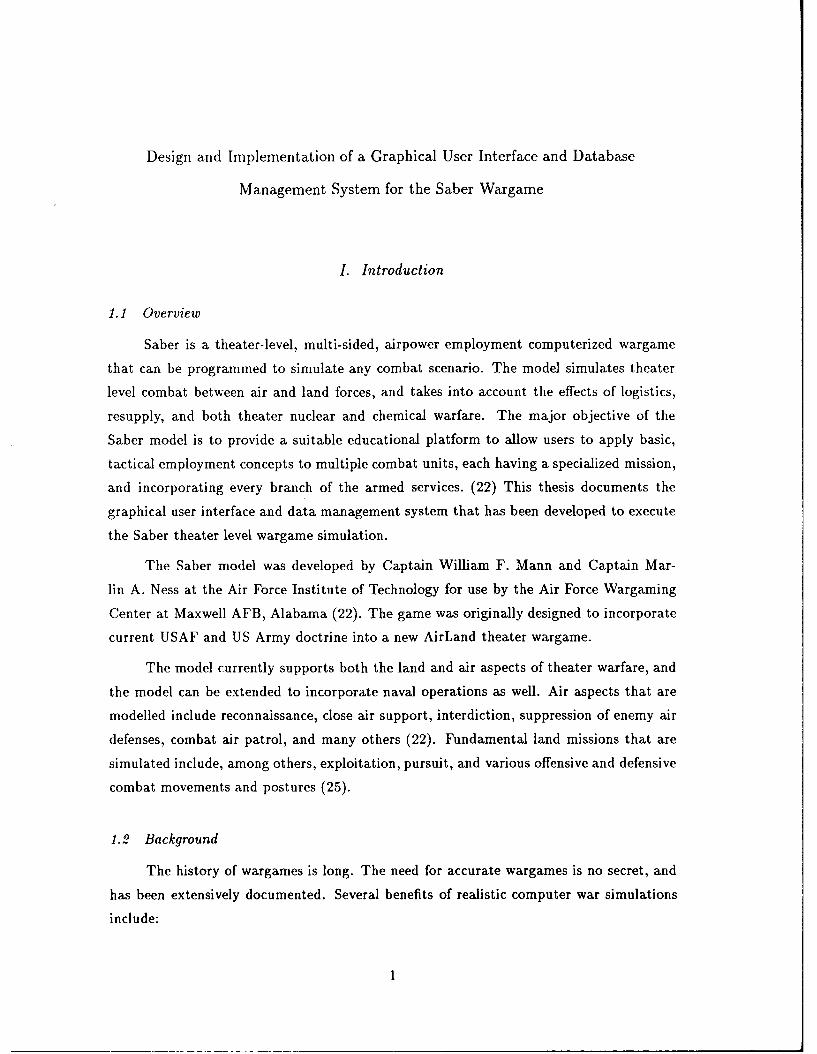
TYPICAL COMBAT MODEL
UFI PR EPROCESSOR FSMU~IN
OUTrPUT
GRAPHSBL3UIE R]ED CHAR'TS
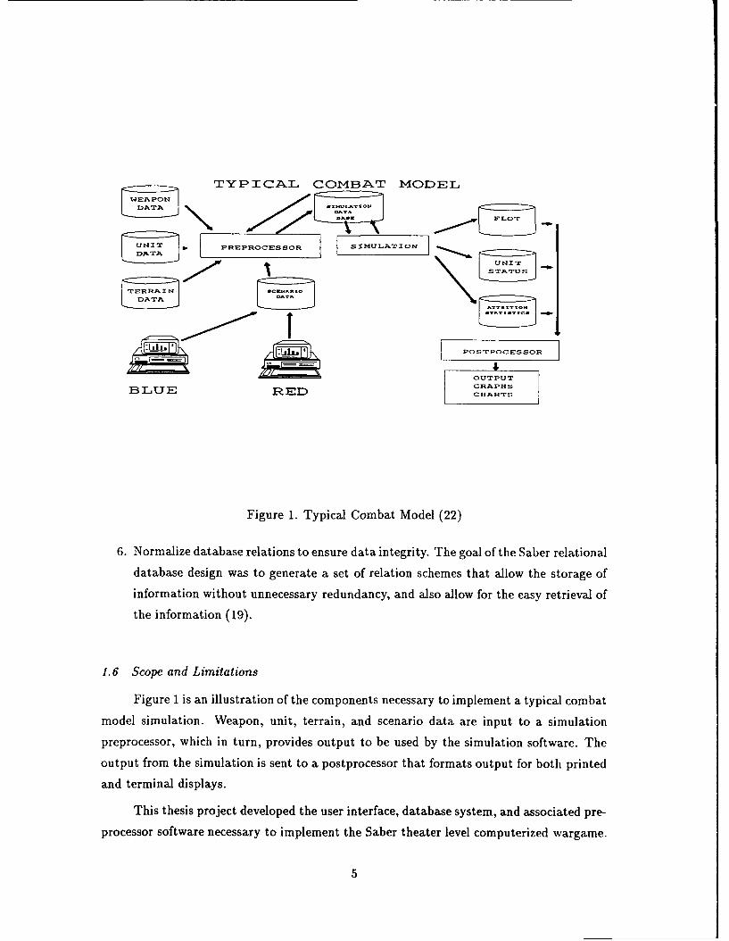
Figure 1. Typical Combat Model (22)
6. Normalize database relations to ensure data integrity. The goal of the Saber relational
database design was to generate a set of relation schemes that allow the storage of
information without unnecessary redundancy, and also allow for the easy retrieval of
the information (19).
1.6 Scope and Limitations
Figure I is an illustration of the components necessary to implement a typical combat
model simulation. Weapon, unit, terrain, and scenario data are input to a simulation
preprocessor, which in turn, provides output to be used by the simulation software. The
output from the simulation is sent to a postprocessor that formats output for both printed
and terminal displays.
This thesis project developed the user interface, database system, and associated pre-
processor software necessary to implement the Saber theater level computerized wargame.
DATA
Another thesis project (30) takes values stored in the Saber DBMS, and applies attrition
algorithms to simulate battlefield scenarios. A third thesis project (16) processes output
from both the Saber DBMS and the simulation results, producing a graphical represen-
tation of the theater war events, and documenting the results of battlefield simulations
through the generation of various reports in a computer printout format.
Verification and validation of the Saber model is to be accomplished by the Air Force
Wargaming Center.
1.7 Materials and Equipment
This thesis effort uses the OSF Motif toolkit along with the X Window System in its
implementation of the user interface. The Saber data management system was designed
and implemented using the Oracle (9) relational DBMS. The software generated as a
result of this thesis can be executed on both the Sun 386i, and on Sun Sparc II compatible
workstations.
1.8 Outline of Document
The remainder of this thesis is organized into 4 additional chapters. Chapter 2 of
this thesis is a summary of previous related research on computerized wargames, and the
interfaces and database management systems that are used to implement them. Chapter 3
describes the methodology used in designing the Saber DBMS, and presents a relational
system using the Oracle DBMS. Chapter 4 defines the implementation of the Saber graph-
ical user interface, and how this interface interacts with the Saber DBMS. Chapter 5
summarizes this thesis effort, gives concluding remarks, and recommends areas of further
research.
6
I. Summary of Current Knowledge
2.1 Overview
This chapter provides an overview of key research in the area of graphical user in-
terfaces and data base management systems as it pertains to computerized versions of
wargames. In the sections that follow, the motivation for the development of the Saber
wargame is discussed, followed by a brief summary of its historical development. Notable
advances in user interface theory are also presented, including a brief survey of comput-
erized wargames and their associated user interface implementations. This chapter then
presents a description of the X Window System, and how it used in the development of the
Saber user interface. Finally, this chapter concludes with a description of relational data-
base design using an object-oriented methodology. This design was used as the foundation
for the Saber data management system.
2.2 User Interface Issues
2.2.1 Background of User Interfaces and Their Design. User interface design has
been recognized as a critically important part of any software system. Kross (20) provides
an excellent summary of the history of user interfaces. In the early days of computers,
the only people who interacted with computers were computer programmers. They were
usually the only users of the computer system, since the interface consisted of hardware
components such as a punch card reader. Today, computers are used by vast numbers
of untrained users. This fact has increased the importance of user-friendly interfaces and
made it one of the highest concerns of the modern software engineer.
In today's modern computing age, the quality of the user interface is often the yard-
stick by which an entire system is judged. An interface which is difficult to use can result
in a high level of user errors, and may even cause the software system to be discarded,
irrespective of the functionality that the system offers (33). Therefore, the interface must
be designed with the needs of the user in mind.
2.2.2 User Interface Design Objectives. For most interactive systems, the screen
displays are a key component to successful user interface designs. A dense or cluttered
display can lead to user errors, and inconsistent formats can inhibit performance and lead
to user frustration. (31)
7
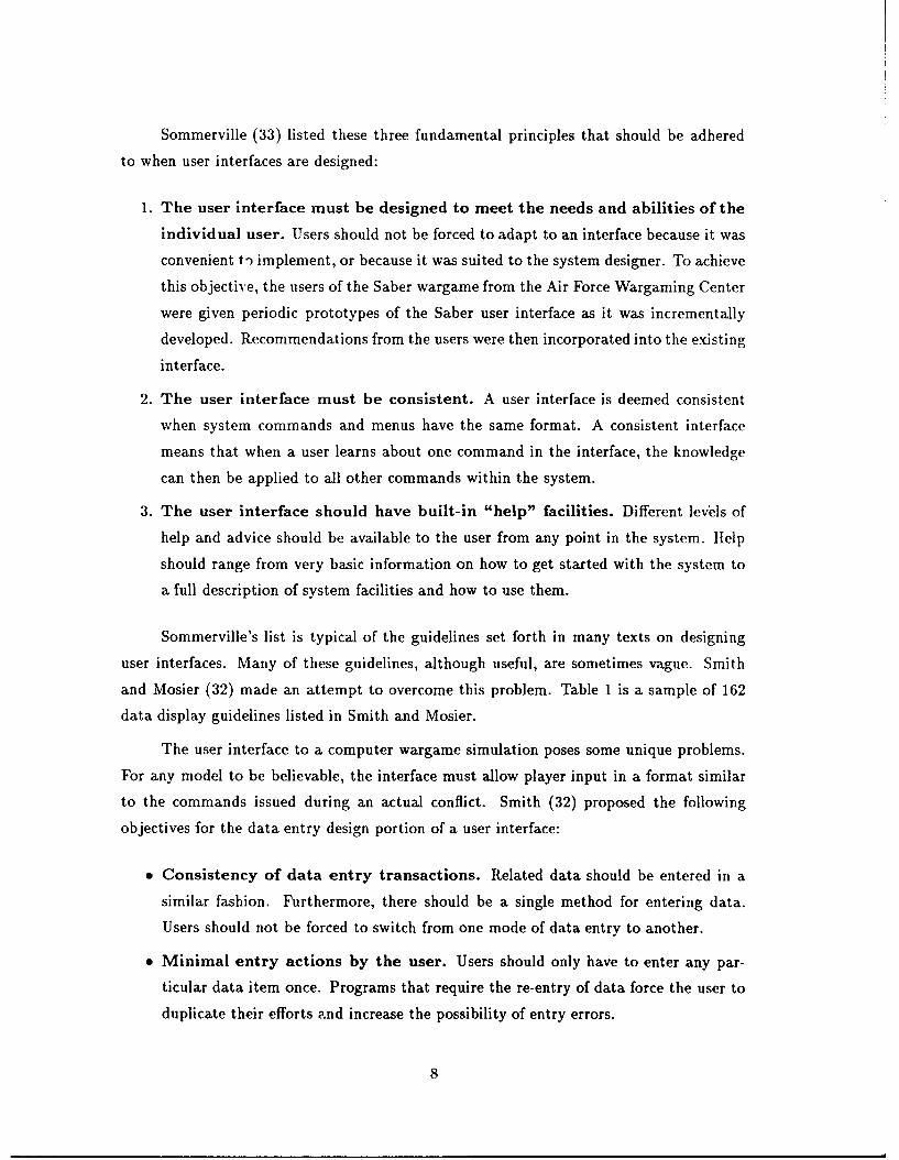
Sommerville (33) listed these three fundamental principles that should be adhered
to when user interfaces are designed:
1. The user interface must be designed to meet the needs and abilities of the
individual user. Users should not be forced to adapt to an interface because it was
convenient to implement, or because it was suited to the system designer. To achieve
this objective, the users of the Saber wargame from the Air Force Wargaming Center
were given periodic prototypes of the Saber user interface as it was incrementally
developed. Recommendations from the users were then incorporated into the existing
interface.
2. The user interface must be consistent. A user interface is deemed consistent
when system commands and menus have the same format. A consistent interface
means that when a user learns about one command in the interface, the knowledge
can then be applied to all other commands within the system.
3. The user interface should have built-in "help" facilities. Different levels of
help and advice should be available to the user from any point in the system. Help
should range from very basic information on how to get started with the system to
a full description of system facilities and how to use them.
Sommerville's list is typical of the guidelines set forth in many texts on designing
user interfaces. Many of these guidelines, although useful, are sometimes vague. Smith
and Mosier (32) made an attempt to overcome this problem. Table 1 is a sample of 162
data display guidelines listed in Smith and Mosier.
The user interface to a computer wargame simulation poses some unique problems.
For any model to be believable, the interface must allow player input in a format similar
to the commands issued during an actual conflict. Smith (32) proposed the following
objectives for the data entry design portion of a user interface:
" Consistency of data entry transactions. Related data should be entered in a
similar fashion. Furthermore, there should be a single method for entering data.
Users should not be forced to switch from one mode of data entry to another.
" Minimal entry actions by the user. Users should only have to enter any par-
ticular data item once. Programs that require the re-entry of data force the user to
duplicate their efforts ,and increase the possibility of entry errors.
8
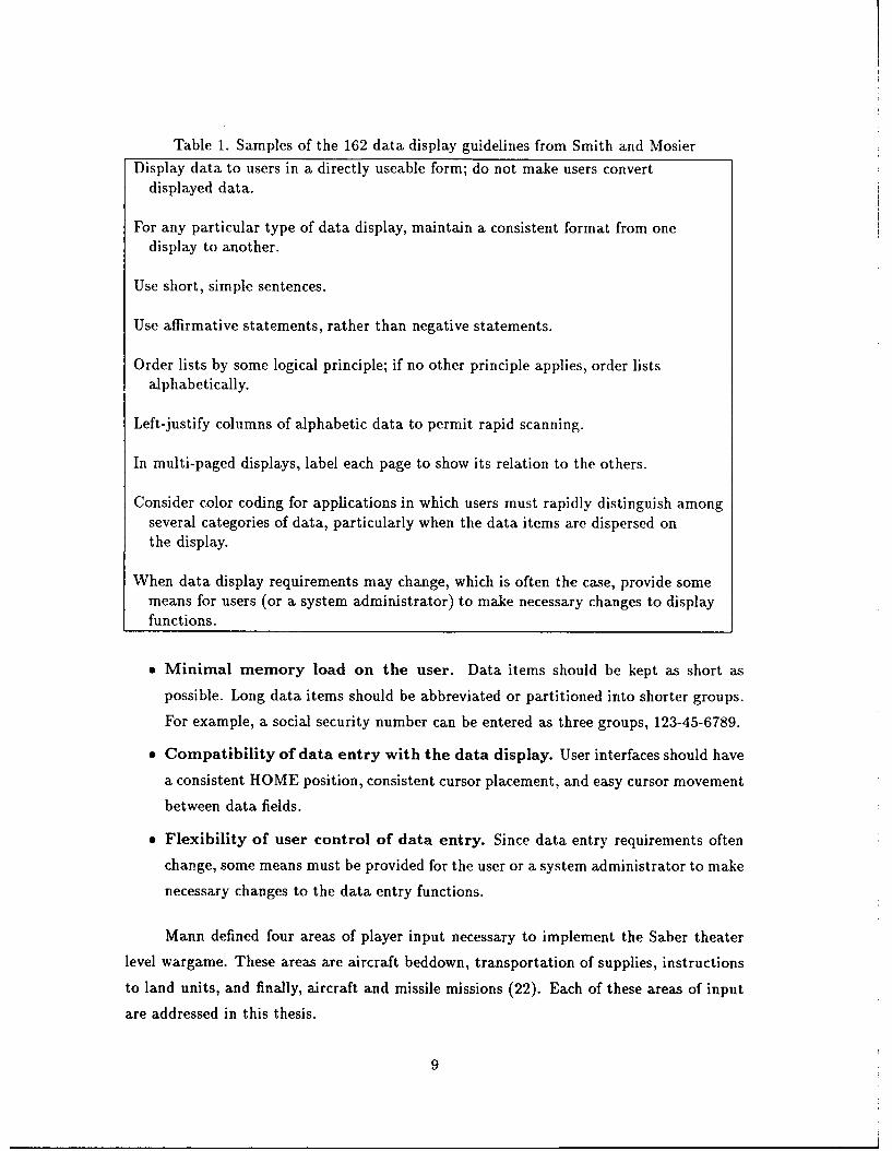
Table 1. Samples of the 162 data display guidelines from Smith and Mosier
Display data to users in a directly useable form; do not make users convertdisplayed data.
For any particular type of data display, maintain a consistent format from onedisplay to another.
Use short, simple sentences.
Use affirmative statements, rather than negative statements.
Order lists by some logical principle; if no other principle applies, order listsalphabetically.
Left-justify columns of alphabetic data to permit rapid scanning.
In multi-paged displays, label each page to show its relation to the others.
Consider color coding for applications in which users must rapidly distinguish amongseveral categories of data, particularly when the data items are dispersed onthe display.
When data display requirements may change, which is often the case, provide somemeans for users (or a system administrator) to make necessary changes to displayfunctions.
" Minimal memory load on the user. Data items should be kept as short as
possible. Long data items should be abbreviated or partitioned into shorter groups.
For example, a social security number can be entered as three groups, 123-45-6789.
" Compatibility of data entry with the data display. User interfaces should have
a consistent HOME position, consistent cursor placement, and easy cursor movement
between data fields.
" Flexibility of user control of data entry. Since data entry requirements often
change, some means must be provided for the user or a system administrator to make
necessary changes to the data entry functions.
Mann defined four areas of player input necessary to implement the Saber theater
level wargame. These areas are aircraft beddown, transportation of supplies, instructions
to land units, and finally, aircraft and missile missions (22). Each of these areas of input
are addressed in this thesis.
9
2.3 The X Window System
The design of user interfaces using windowing environments is relatively new in the
field of computer science. Windows have the advantage of allowing several pieces of infor-
mation or documents to be displayed at one time.
Graphical user interfaces that use some type of windowing system are a common
feature to many of the current software packages available in today's modern computer
age. As a result, users have come to expect all applications they work with to have a pro-
fessional, user-friendly interface (39). The X Window System, or simply X, is one software
system that provides the necessary facilities to allow programmers to efficiently develop
professional graphical user interfaces (39). A full description of X and its capabilities can
be found in (13, 14, 26, 29, 39).
X is a network-transparent window system that enables users to simultaneously run
multiple applications in separate windows (29). X was developed in 1984 at the Mas-
sachusetts Institute of Technology (MIT) to fulfill the need for a distributed, hardware-
independent graphical user interface platform (39). Since its version 10 release in 1986,
X has been adopted as a standard by nearly every workstation manufacturer, and should
eventually replace or be supported under their proprietary windowing systems(26). One of
the requirements for implementing Saber was for the software generated to execute on the
Sun 386i, and Sun Sparc H compatible workstations. Since X software packages can be
executed on several different types of incompatible machines, the X Window System has
proven to be an appropriate choice for building the graphical user interface for the Saber
theater level wargame.
2.4 OSE/Motif
One interface to X is a C language library known as Xlib (39). Although applications
can be built in their entirety using Xlib, the Xlib library can be tedious and difficult to use
correctly. The window manager conventions alone require the programming of hundreds of
lines of code. (39) To make X programming easier and less time consuming, Open Software
Foundation (OSF) developed a high-level toolkit known as Motif (27).
Motif allows X programmers to be more productive by hiding many X Windows
implementation details from the programmer. With Motif, creating and manipulating
windows on a screen is simpler and requires less lines of code to be programmed.
10
Motif increases user productivity by supplying the user with an application toolkit,
a window manager, and a user interface language. The Motif toolkit consists of a set
of functions and procedures, known as widgets and gadgets, that provide quick and easy
access to the lower levels of the X Window system. The window manager provides for the
direct manipulation of graphic objects. The placing and sizing of windows, icon definitions,
and communications between different applications are all handled by the window manager.
The Motif user interface language, or UIL, is a specification language for describing the
initial state of a user interface for a Motif application. The specification describes the
objects used in the interface, such as menus, form boxes, labels, and push buttons. The
specification also describes which functions are to be called when the interface changes
state as a result of user interaction. A detailed description of each of these productivity
tools can be found in (27).
2.5 Saber Database Management
2.5.1 Database Management Concerns. The data required to implement Saber will
be stored in fiat files that can be accessed by a relational database. Database management
systems offer a number of major advantages over directly manipulating flat files. Korth
(19) and Date (6) present these advantageous of using a DBMS to control data versus
using a file-processing system.
" Data redundancy and inconsistency can be reduced. Redundancy leads to
higher storage and access cost as well as potential data inconsistency. Any partic-
ular value of a data item should be stored in one location, if feasible. This can be
accomplished through proper normalization of the data items being stored.
" Data integrity can be maintained. The values stored in the database must
be accurate and must satisfy consistency constraints. For example, the number of
aircraft in a strike package can never be a negative number.
" Multiple users can share data. A DBMS usually has a built-in mechanism to
allow multiple users to access the same data simultaneously without sacrificing data
integrity.
" Standards can be enforced. A DBMS can aid in ensuring that data items are
stored in the proper format. For example, a DBMS can inform the users to input a
date in YYMMDD format if they attempt to enter the date in any other format.
11
e Security restrictions can be readily applied. Not every user of Saber should be
able to access all the data stored in the Saber DBMS. Since application programs,
such as report writers, are added to a system in an ad hoc manner, the use of DBMS
can aid in the enforcement of security constraints.
The goal of a DBMS is to provide an environment that is both convenient and efficient to
use in retrieving information from and storing information into a database (19).
2.5.2 The ORACLE Database Management System. ORACLE is a relational data-
base system produced by Oracle Corporation of Belmont, California. ORACLE includes
a complete set of integrated software productivity tools for application development and
data analysis. Versions of ORACLE exist that run on a wide range of machines, from
desktop personal computers mainframes. This flexibility allows organizations to use
heterogeneous hardware but still operate in a standard software environment for applica-
tions. (9) ORACLE has been used for development of the Saber DBMS at the request of
the Air Force Wargaming Center. ORACLE provides the following tools for programmers
to create and maintain their own applications (9).
" Application Generator and Screen Formatter.
" Report Writer.
" Color Graphics.
" Document Preparation and Text Merging.
" Integrated Data Dictionary.
Each of these tools were used in the development of the Saber DBMS. These software pro-
ductivity tools are run on both the Sun 386i and on Sun Sparc Hcompatible workstations,
which are the required hardware platforms for the Saber Theater level wargame. These
tools can continue to be used to modify and maintain the Saber DBMS as the need arises.
2.6 User Interface Applications of Existing Wargames
This section presents an overview of theses on user interfaces for wargames, and on
the user interfaces that currently exist on computerized versions of wargames.
12
2.6.1 Theatcr Analysis Model AirLand Campaign Model. The Theater Analysis
Model (TAM) system (11) is a set of wargame models used by the Joint Staff, Politico-
Military Assessment Division (PMAD). The TAM system currently consists of four compo-
nents, specifically, Maritime Canra aign, AirLand Campaign, Air Engagement, and Naval
Engagement Models. (11) The interface and data management system for the AirLand
Campaign Model are reviewed here.
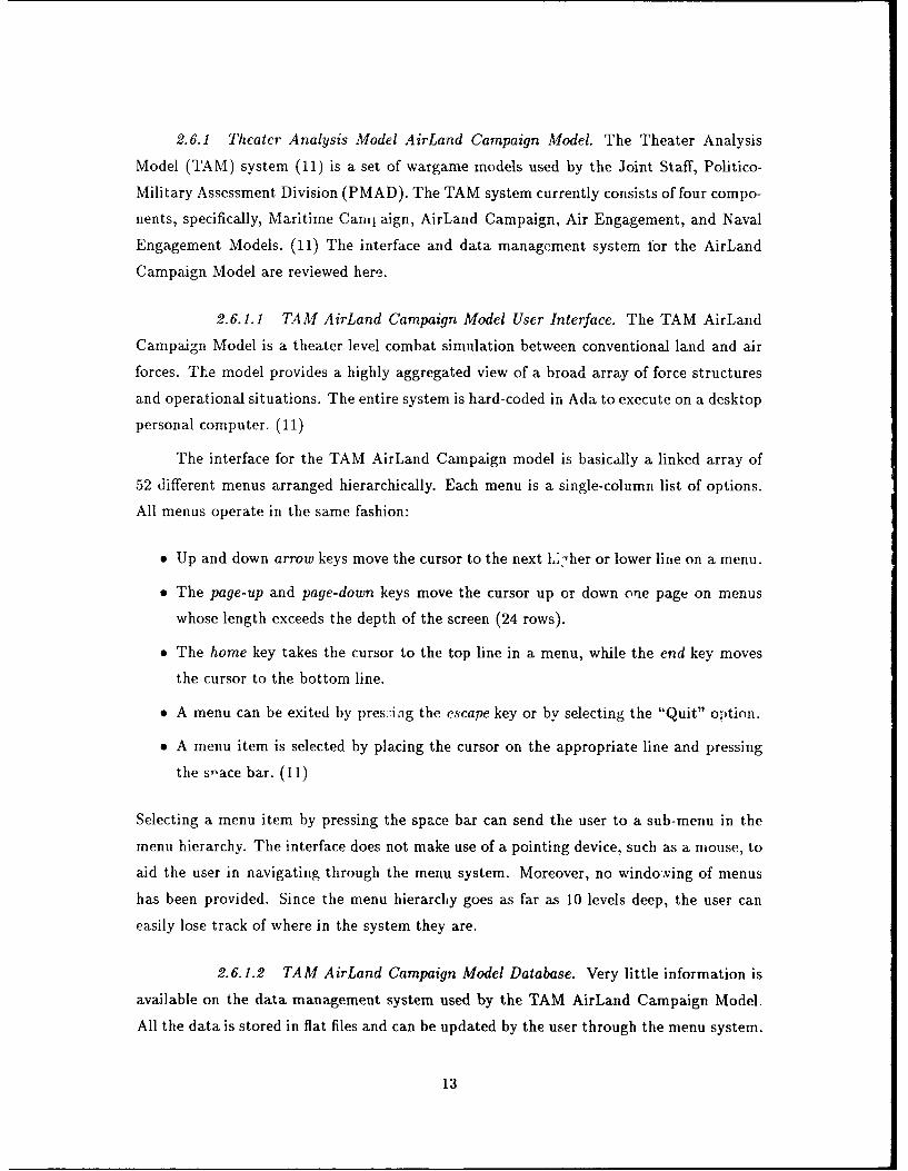
2.6.1.1 TAM AirLand Campaign Model User Interface. The TAM AirLand
Campaign Model is a theater level combat simulation between conventional land and air
forces. The model provides a highly aggregated view of a broad array of force structures
and operational situations. The entire system is hard-coded in Ada to execute on a desktop
personal computer. (11)
The interface for the TAM AirLand Campaign model is basically a linked array of
52 different menus arranged hierarchically. Each menu is a single-column list of options.
All menus operate in the same fashion:
" Up and down arrow keys move the cursor to the next L-her or lower line on a menu.
" The page-up and page-down keys move the cursor up or down one page on menus
whose length exceeds the depth of the screen (24 rows).
" The home key takes the cursor to the top line in a menu, while the end key moves
the cursor to the bottom line.
" A menu can be exited by pres7iag the escape key or by selecting the "Quit" option.
* A menu item is selected by placing the cursor on the appropriate line and pressing
the space bar. (11)
Selecting a menu item by pressing the space bar can send the user to a sub-menu in the
menu hierarchy. The interface does not make use of a pointing device, such as a mouse, to
aid the user in navigating through the menu system. Moreover, no windo.ving of menus
has been provided. Since the menu hierarchy goes as far as 10 levels deep, the user can
easily lose track of where in the system they are.
2.6.1.2 TAM AirLand Campaign Model Database. Very little information is
available on the data management system used by the TAM AirLand Campaign Model.
All the data is stored in flat files and can be updated by the user through the menu system.
13
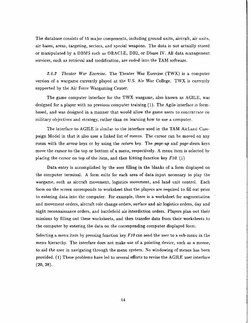
The database consists of 15 major components, including ground units, aircraft, air units,
air bases, areas, targeting, sectors, and special weapons. The data is not actually stored
or manipulated by a DBMS such as ORACLE, DB2, or Dbase IV. All data management
services, such as retrieval and modification, are coded into the TAM software.
2.6.2 Theater War Exercise. The Theater War Exercise (TWX) is a computer
version of a wargame currently played at the U.S. Air War College. TWX is currently
supported by the Air Force Wargaming Center.
The game computer interface for the TWX wargame, also known as AGILE, was
designed for a player with no previous computer training (1). The Agile interface is form-
based, and was designed in a manner that would allow the game users to concentrate on
military objectives and strategy, rather than on learning how to use a computer.
The interface to AGILE is similar to the interface used in the TAM AirLand Cam-
paign Model in that it also uses a linked list of menus. The cursor can be moved on any
menu with the arrow keys or by using the return key. The page-up and page-down keys
move the cursor to the top or bottom of a menu, respectively. A menu item is selected by
placing the cursor on top of the item, and then hitting function key F1O. (1)
Data entry is accomplished by the user filling in the blanks of a form displayed on
the computer terminal. A form exits for each area of data input necessary to play the
wargame, such as aircraft movement, logistics movement, and land unit control. Each
form on the screen corresponds to worksheet that the players are required to fill out prior
to entering data into the computer. For example, there is a worksheet for augmentation
and movement orders, aircraft role change orders, surface and air logistics orders, day and
night reconnaissance orders, and battlefield air interdiction orders. Players plan out their
missions by filling out these worksheets, and then transfer data from their worksheets to
the computer by entering the data on the corresponding computer displayed form.
Selecting a menu item by pressing function key F1O can send the user to a sub-menu in the
menu hierarchy. The interface does not make use of a pointing device, such as a mouse,
to aid the user in navigating through the menu system. No windowing of menus has been
provided. (1) These problems have led to several efforts to revise the AGILE user interface
(20,38).
14
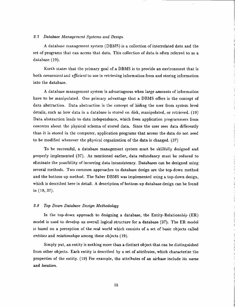
2.7 Database Management Systems and Design
A database management system (DBMS) is a collection of interrelated data and the
set of programs that can access that data. This collection of data is often referred to as a
database (19).
Korth states that the primary goal of a DBMS is to provide an environment that is
both convenient and efficient to use in retrieving information from and storing information
into the database.
A database management system is advantageous when large amounts of information
have to be manipulated. One primary advantage that a DBMS offers is the concept of
data abstraction. Data abstraction is the concept of hiding the user from system level
details, such as how data in a database is stored on disk, manipulated, or retrieved. (19)
Data abstraction leads to data independence, which frees application programmers from
concerns about the physical schema of stored data. Since the user sees data differently
than it is stored in the computer, application programs that access the data do not need
to be modified whenever the physical organization of the data is changed. (37)
To be successful, a database management system must be skillfully designed and
properly implemented (37). As mentioned earlier, data redundancy must be reduced to
eliminate the possibility of incurring data inconsistency. Databases can be designed using
several methods. Two common approaches to database design are the top-down method
and the bottom-up method. The Saber DBMS was implemented using a top-down design,
which is described here in detail. A description of bottom-up database design can be found
in (19, 37).
2.8 Top Down Database Design Methodology
In the top-down approach to designing a database, the Entity-Relationship (ER)
model is used to develop an overall logical structure for a database (37). The ER model
is based on a perception of the real world which consists of a set of basic objects called
entities and relationships among these objects (19).
Simply put, an entity is nothing more than a distinct object that can be distinguished
from other objects. Each entity is described by a set of attributes, which characterize the
properties of the entity. (19) For example, the attributes of an airbase include its name
and location.
15
Airbases, hexes, land units, and aircraft all represent entities in the Saber data-
base system. A relation is the affiliation, association, or connection between two or more
entities. An example of a relationship is the association of an aircraft to the airbase it is as-
signed to. Two special relationships between entities are generalization and specialization.
Specialization involves adapting or tailoring an entity to a specific function, or supplying
the entity with specific characteristics. For example, a helicopter is a specialization of a
generic aircraft entity. Generalization is the opposite of specialization. In generalization,
specific characteristics of an entity are hidden. (19)
One important constraint in the ER model is mapping cardinalities which describe
the number of entities from one entity set that can be associated with any given entity in
another entity set. There are four types of mapping cardinalities.
* One-to-one relationship, denoted (1:1).
" One-to-many relationship, denoted (1:N).
" Many-to-one relationship, denoted (N:1).
" Many-to-many relationship, denoted (M:N).
A one-to-one relationship states that one entity from one set can be associated with one
and only one entity from another set. Considering no land unit can be in more than one
place at a time, there is a one-to-one relationship between a land unit and the hex that it
resides in. A description of all four types of mapping cardinalities can be found in (19).
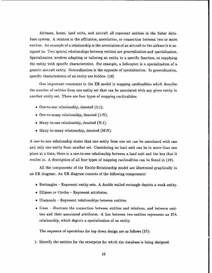
All the components of the Entity-Relationship model are illustrated graphically in
an ER diagram. An ER diagram consists of the following components:
* Rectangles - Represent entity sets. A double walled rectangle depicts a weak entity.
* Ellipses or Circles - Represent attributes.
" Diamonds - Represent relationships between entities.
" Lines - illustrate the connection between entities and relations, and between enti-
ties and their associated attributes. A line between two entities represents an ISA
relationship, which depicts a specialization of an entity.
The sequence of operations for top down design are as follows (37):
1. Identify the entities for the enterprise for which the database is being designed.
16
All Relations (Normalized and Unnormalized)
1 NF Relations
2NF Relations
3NF Relations
SBCNF Relations
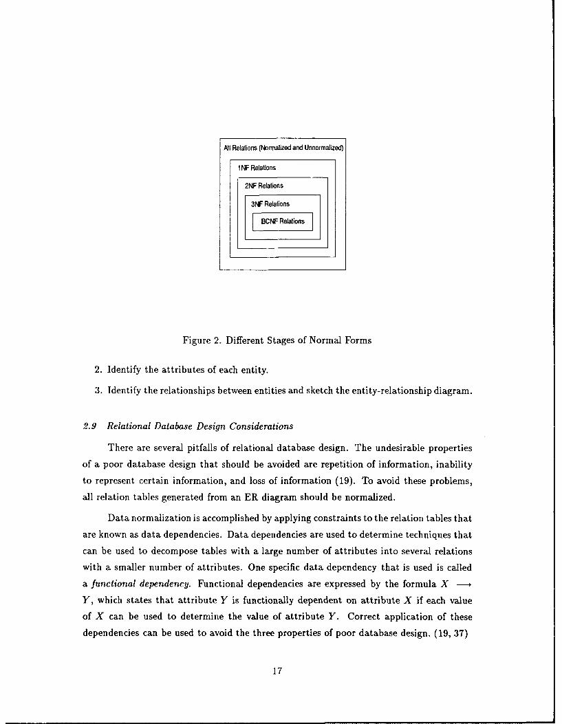
Figure 2. Different Stages of Normal Forms
2. Identify the attributes of each entity.
3. Identify the relationships between entities and sketch the entity-relationship diagram.
2.9 Relational Database Design Considerations
There are several pitfalls of relational database design. The undesirable properties
of a poor database design that should be avoided are repetition of information, inability
to represent certain information, and loss of information (19). To avoid these problems,
all relation tables generated from an ER diagram should be normalized.
Data normalization is accomplished by applying constraints to the relation tables that
are known as data dependencies. Data dependencies are used to determine techniques that
can be used to decompose tables with a large number of attributes into several relations
with a smaller number of attributes. One specific data dependency that is used is called
a functional dependency. Functional dependencies are expressed by the formula X
Y, which states that attribute Y is functionally dependent on attribute X if each value
of X can be used to determine the value of attribute Y. Correct application of these
dependencies can be used to avoid the three properties of poor database design. (19, 37)
17

In data normalization, functional dependencies are used to decompose tables into an
appropriate normal form. A normal form is the degree of data replication and redundancy
that exists within a given relation. Normal forms are usually characterized in levels known
as first, second, third, and Boyce Codd normal forms (BCNF), as depicted in Figure 2.
Certain undesirable features are eliminated from an unnormalized relation as the relation
is normalized to successive normal form stages.
Several different approaches can be taken to progress from one normal form stage
to the next. "The rules leading to and including third normal form can be summed up
in a single statement: Each attribute must be a fact about the key, the whole key, and
nothing but the key" (28). Rettig cites these five rules that should be followed for data
normalization (28).
1. Eliminate repeating groups. Make a separate relation table for each set of related
attributes, and give each table a primary key.
2. Eliminate redundant data. If an attribute depends on only part of a multi-valued
key, remove it to a separate table.
3. Eliminate columns not dependent on the primary key. If attributes do not contribute
to a description of the key, remove them to a separate table.
4. Isolate independent multiple relationships. No table may contain two or more 1:M
or N:M relationships that are not directly related. This applies only to relationships
that include one-to-many and many-to-many relationships.
5. Isolate semantically related multiple relationships. There may be practical con-
straints on information that justify separating logically related many-to-many re-
lations.
Normalization of data is used to avoid the pitfalls of bad database design. In sum-
mary, normalization ensures that relations are broken into simpler relations in which related
data items are grouped, and that duplication of data is kept at a minimum (37).
2.10 Summary
The goal of this chapter was to familiarize the reader with several key topics related
to this research. This chapter introduced graphical user interfaces and their implemen-
tations in computerized wargames. A relational database design using an object-oriented
18
methodology was also presented in this chapter. The following chapters describe in de-
tail the implementation of the Saber graphical user interface and database management
system.
19
III. Saber Database Implementation
This chapter gives a description of the process that was followed in implementing the
Saber database system. The first step in the design consisted of an analyis of the problem
domain to identify all the entities that needed to be modelled. The entities are described
in Section 3.1, along with the process that was followed to produce ER diagrams that
represented these entities. The second section details the steps taken to convert the Saber
ER diagrams to relation tables. The next section is a detailed description of the Saber
database tables that were created, and how they are used to store wargame information.
Section 3.4 gives a description of the files used to upload and download data from the Oracle
database to flat ASCII files. Finally, Section 3.5 discusses verification and validation issues
as they relate to the Saber DBMS.
3.1 Saber Top Down Design
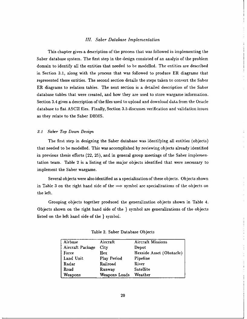
The first step in designing the Saber database was identifying all entities (objects)
that needed to be modelled. This was accomplished by reviewing objects already identified
in previous thesis efforts (22, 25), and in general group meetings of the Saber implemen-
tation team. Table 2 is a listing of the major objects identified that were necessary to
implement the Saber wargame.
Several objects were also identified as a specialization of these objects. Objects shown
in Table 3 on the right hand side of the ==* symbol are specializations of the objects on
the left.
Grouping objects together produced the generalization objects shown in Table 4.
Objects shown on the right hand side of the } symbol are generalizations of the objects
listed on the left hand side of the } symbol.
Table 2. Saber Database Objects
Airbase Aircraft Aircraft MissionsAircraft Package City DepotFbrce Hex Ilexside Asset (Obstacle)Land Unit Play Period PipelineRadar Railroad RiverRoad Runway SatelliteWeapons Weapons Loads Weather
20
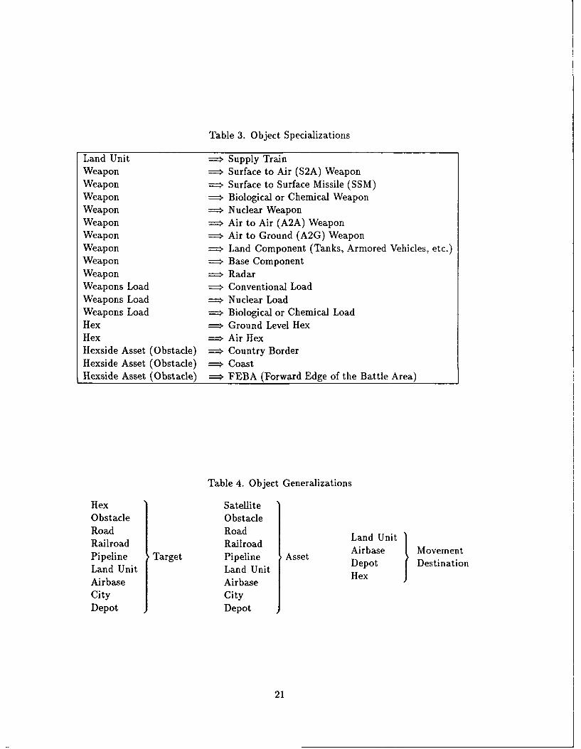
Table 3. Object Specializations
Land Unit = Supply TrainWeapon ==. Surface to Air (S2A) WeaponWeapon == Surface to Surface Missile (SSM)Weapon => Biological or Chemical WeaponWeapon = Nuclear WeaponWeapon == Air to Air (A2A) WeaponWeapon = Air to Ground (A2G) WeaponWeapon ==' Land Component (Tanks, Armored Vehicles, etc.)Weapon = Base ComponentWeapon ==. RadarWeapons Load == Conventional LoadWeapons Load == Nuclear LoadWeapons Load == Biological or Chemical LoadHex == Ground Level HexHex == Air HexHexside Asset (Obstacle) = Country BorderHexside Asset (Obstacle) == CoastHexside Asset (Obstacle) = FEBA (Forward Edge of the Battle Area)
Table 4. Object Generalizations
Hex SatelliteObstacle ObstacleRoad RoadRailroad RailroadLadUiRalradRarodAirbase MovementPipeline Target Pipeline Asset Depot DestinationLand Unit Land Unit HexAirbase AirbaseCity CityDepot Depot
21
The second step in designing the Saber database using the top-down approach was to
identify attributes for each of these entities. The complete relational design can be found
in Appendix A. Definitions of attributes and the legal range of values they can take on
can be found in the Saber Data Dictionary located in Appendix B.
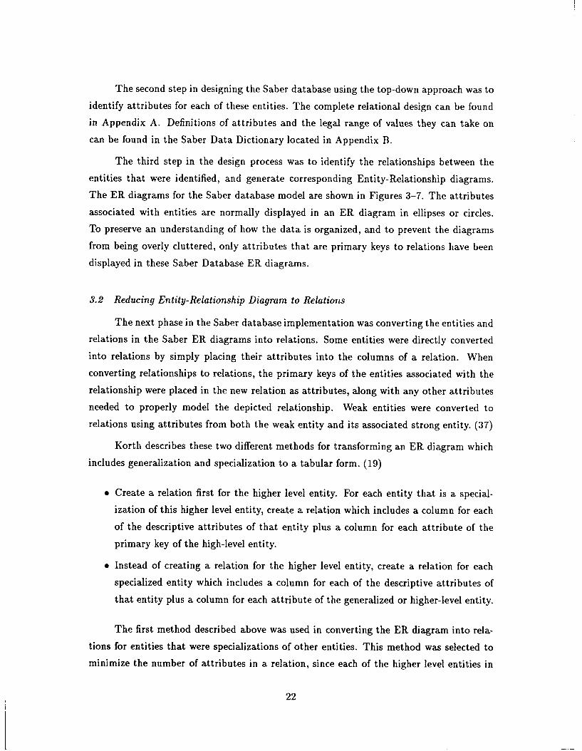
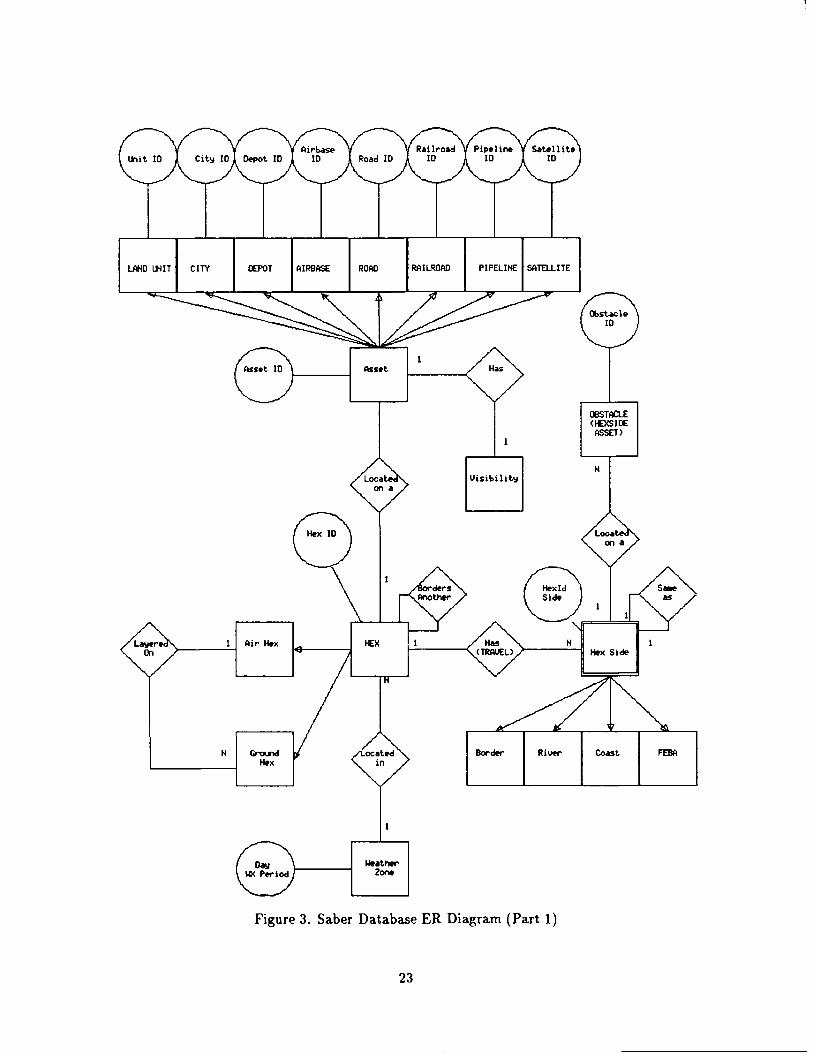
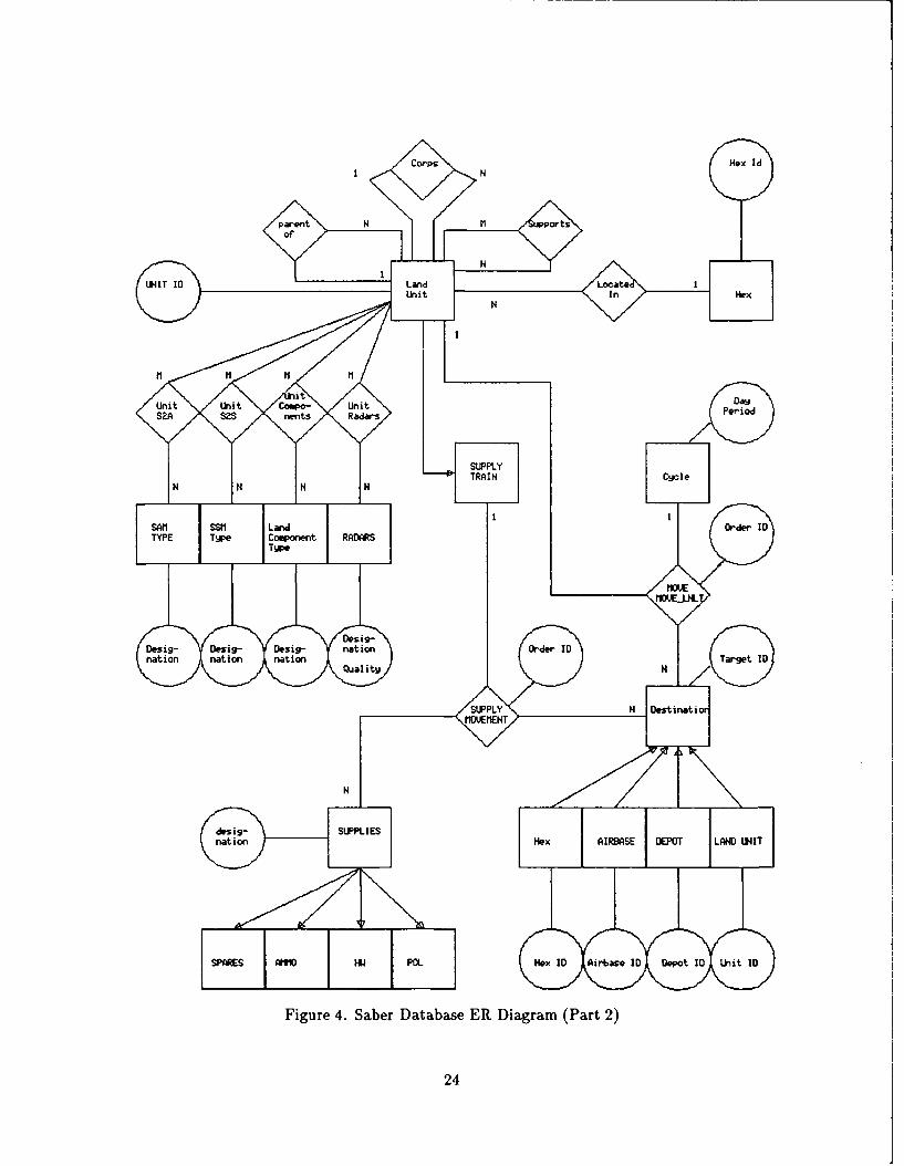
The third step in the design process was to identify the relationships between the
entities that were identified, and generate corresponding Entity-Relationship diagrams.
The ER diagrams for the Saber database model are shown in Figures 3-7. The attributes
associated with entities are normally displayed in an ER diagram in ellipses or circles.
To preserve an understanding of how the data is organized, and to prevent the diagrams
from being overly cluttered, only attributes that are primary keys to relations have been
displayed in these Saber Database ER diagrams.
3.2 Reducing Entity-Relationship Diagram to Relations
The next phase in the Saber database implementation was converting the entities and
relations in the Saber ER diagrams into relations. Some entities were directly converted
into relations by simply placing their attributes into the columns of a relation. When
converting relationships to relations, the primary keys of the entities associated with the
relationship were placed in the new relation as attributes, along with any other attributes
needed to properly model the depicted relationship. Weak entities were converted to
relations using attributes from both the weak entity and its associated strong entity. (37)
Korth describes these two different methods for transforming an ER diagram which
includes generalization and specialization to a tabular form. (19)
" Create a relation first for the higher level entity. For each entity that is a special-
ization of this higher level entity, create a relation which includes a column for each
of the descriptive attributes of that entity plus a column for each attribute of the
primary key of the high-level entity.
" Instead of creating a relation for the higher level entity, create a relation for each
specialized entity which includes a column for each of the descriptive attributes of
that entity plus a column for each attribute of the generalized or higher-level entity.
The first method described above was used in converting the ER diagram into rela-
tions for entities that were specializations of other entities. This method was selected to
minimize the number of attributes in a relation, since each of the higher level entities in
22
LANDO UNIT CITY DEPOT AIRBASE ROA RAILROAD IPIPELINE SATELLITE
10tc~
II
OBSTACLE(HEXSIDEASSET)
H
HexID oconn a
AnoherSidea
Lalee erio HexHasN
Figure 3. Saber Database ER Diagram (Part 1)
23
Corps Hex IdI N
parent N M ports04,
NI
UNIT ID Land LocateUnit In Hex
N
11 M M M
Unit Uni Daycompo- unit Period
2A SzS nents Radars
L SUPPLYTRAIN Cycle
N N N N
I ISAM SSM Land Order IDTYPE Type Component RADARS
Type
mowMDVEJHL
Desig-Desig- Desig- nation Order ID
)n nation nation Quality H Target ID
SUPPLY N DestinatiMOVEMENT
N
desig- SUPPLIESnation Hex AIRBASE WOT LAND UNIT
SPARES AM1MO HW POL :H..
_:ID)(Ai ID O,,ot 10 Unit ID
Figure 4. Saber Database ER Diagram (Part 2)
24
Mission Missg-ionTq'e Desig- designai
natonSeon4dar-mission
UalidMission
Mision ID
Primar Aiba. rc rradft ieie btal Ctafe
uiini Tqibae RadI aira Pipkaeln Obace Ct d eotD
Figurere 5. Sae DaaaeEIiarm(at3
Conven-Rend25
Biological, Nf uclear A2A A2G
Weapons
NDesig-nation
Figre6. abrataasE DIga (Part 4)rc
26
as
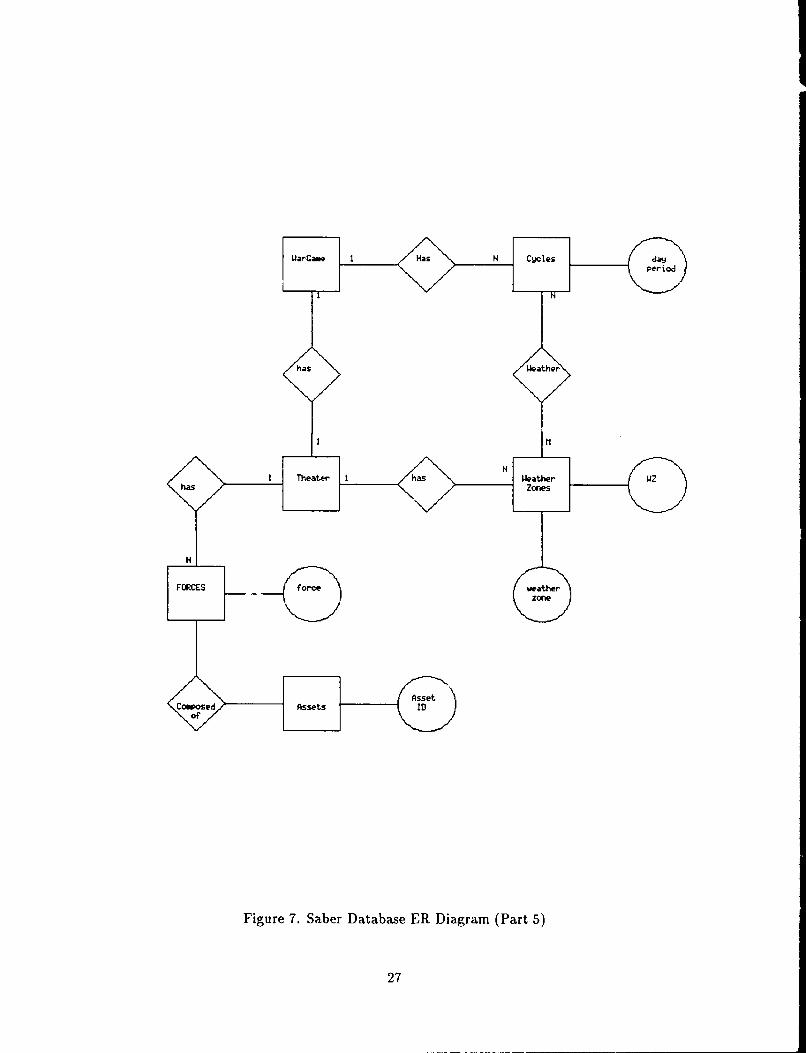
I Theae II ha ethrhas e
Figure 7. Saber Database ER Diagram (Part 5)
27
C p Net UonLnUi
Desig- Weaponeap NsUi ntI
Compoent Compoien-cla
Load
Figur 8.SbrDtbM RDarm(at6
to aWeapn Wapon Comr28
NORTH
NORTHWEST / NORTHEAST
NO RTHO
R
SOUTHWEST
- -
SOUTH
Figure 9. Ground level hex
the Saber model are composed of a large number of attributes, including one relation with
over 40 attributes.
3.3 SABER Database Implementation
The following sections detail the specific implementation of the Saber database.
3.3.1 The Hex, Airhex, and Travel Relations. The Saber wargame is similar to
many common wargames that use a gameboard in that terrain features are modelled using
hexagons (hexes). A typical gameboard wargame usually consists of a terrain map that has
been overlaid with grids or hexagons. The hexagonal grid is used to regulate movement and
the pcsition of units. (7) Ness gives a discussion on hexagonal terrain model representation
in (25).
The Saber wargame also incorporates the concept of air hexes. Air hexes are de-
scribed by Mann in (22). Basically, an air hex is the aggregation of seven ground level
hexes, as shown in Figure 10. Air hexes are stacked six levels deep on top of a ground hex
to simulate levels of altitude from ground level to outer space.
29
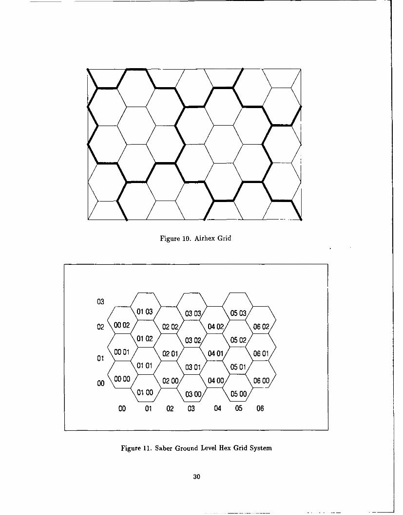
Figure 10. Airhex Grid
03
010 00 0200 040
0100300 0500
00 01 02 03 04 05 06
Figure 11. Saber Ground Level Hex Grid System
30
HX012712 N = HX012713 S
HX01 2712
Figure 12. Neighbor ID
The Saber model uses a ground level hex with vertices (points) that are oriented in
an east-west direction, as shown in Figure 9. The hex relation is the foundation for the
entire Saber computerized wargame. Most entities in the wargame can be mapped to a hex
position. Ground level hexes are labeled in accordance with an X-Y coordinate system, in
that the hex closest to a point of origin (for a given theater) is given a hex location of (0,0).
Hexes are labelled sequentially from the hex at location(0,0), or in other words, from left
to right and from bottom to top. The ground hex location due north of the origin hex has
an X-coordinate of 0 and a Y-coordinate of 1. Figure 11 depicts the Saber basic hexagonal
coordinate system and its numbering scheme.
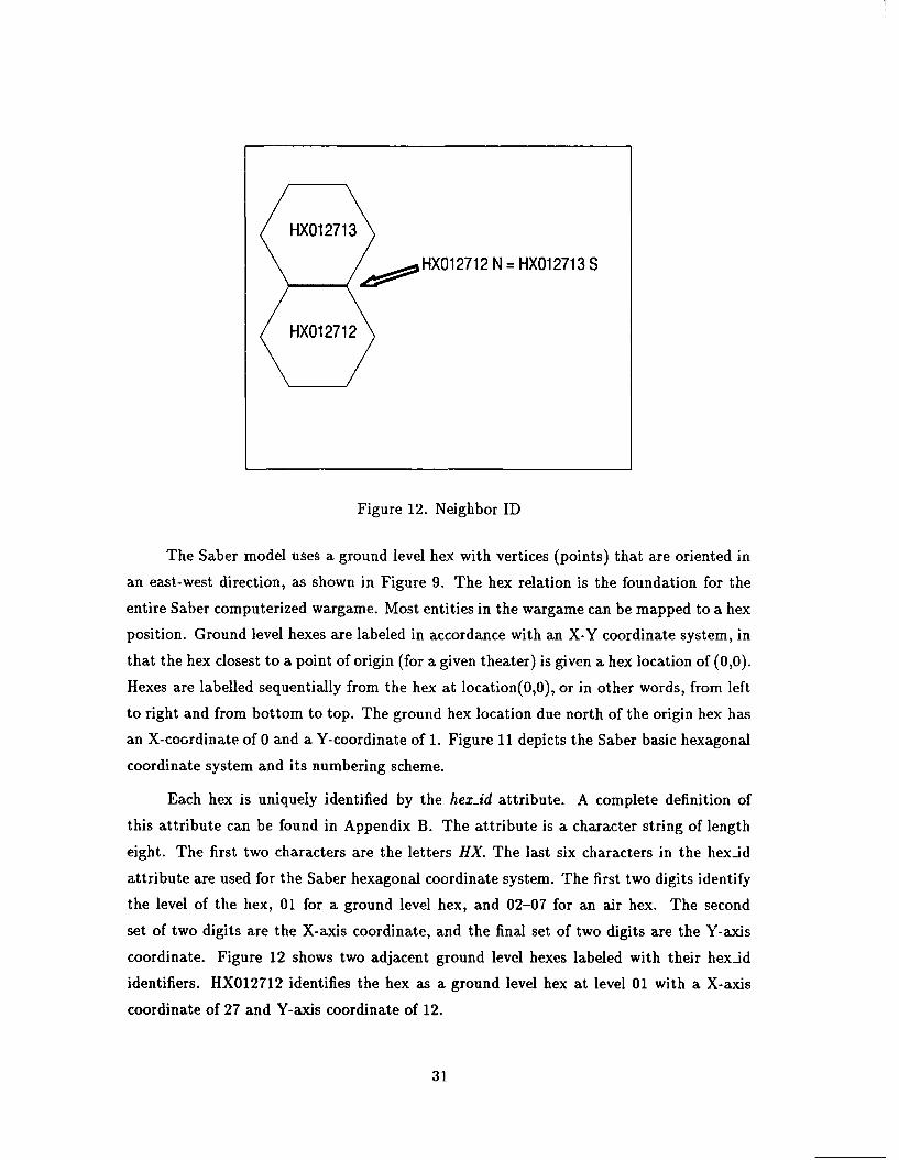
Each hex is uniquely identified by the hex-id attribute. A complete definition of
this attribute can be found in Appendix B. The attribute is a character string of length
eight. The first two characters are the letters HX. The last six characters in the hexid
attribute are used for the Saber hexagonal coordinate system. The first two digits identify
the level of the hex, 01 for a ground level hex, and 02-07 for an air hex. The second
set of two digits are the X-axis coordinate, and the final set of two digits are the Y-axis
coordinate. Figure 12 shows two adjacent ground level hexes labeled with their hexid
identifiers. HX012712 identifies the hex as a ground level hex at level 01 with a X-axis
coordinate of 27 and Y-axis coordinate of 12.
31
HX01 0912 .,,,'HX011112
HX011010/
Figure 13. Center Hex
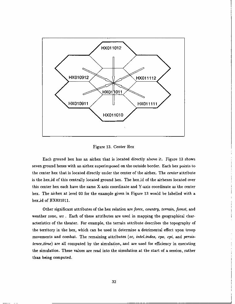
Each ground hex has an airhex that is located directly above it. Figure 13 shows
seven ground hexes with an airhex superimposed on the outside border. Each hex points to
the center hex that is located directly under the center of the airhex. The center attribute
is the hexad of this centrally located ground hex. The hexid of the airhexes located over
this center hex each have the same X-axis coordinate and Y-axis coordinate as the center
hex. The airhex at level 03 for the example given in Figure 13 would be labelled with a
hexid of HX031011.
Other significant attributes of the hex relation are force, country, terrain, forest, and
weather zone, wz. Each of these attributes are used in mapping the geographical char-
acteristics of the theater. For example, the terrain attribute describes the topography of
the territory in the hex, which can be used in determine a detrimental effect upon troop
movements and combat. The remaining attributes (ec, inteLindex, cpo, cpi, and persis-
tence-time) are all computed by the simulation, and are used for efficiency in executing
the simulation. These values are read into the simulation at the start of a session, rather
than being computed.
32
The airhex entity is actually a specialization of the hex entity, retaining only the
hexid, wz, and persistence-time attributes. The trafficability attribute was added to com-
pensate for mountains that might extend up into the lower levels of the airhexes. Aircraft
flying through airhexes with a trafficability value other than excellent are subject to a time
delay penalty. For example, aircraft flying through a hex with a trafficability of excellent
are assessed no time delays, while an airhex with a trafficability of fair are assessed a time
delay equivalent to 20 minutes.
The travel relation stores information on the amount of time it would take a land
unit to travel from the center of a hex to one of its borders. The key to the relation is
a combination of the hexjd identifier and its directional hexside (North, Northeast, etc.).
Each hex is divided into six pie pieces, formed by connecting opposite hex vertices with a
line. Figure 9 shows a ground level hex with the northeast pie piece highlighted. Each pie
piece within a hex has its own pie trafficability value. Hexes that have a mountain terrain
are given pie trafficability values of poor or very poor for all six pie pieces. A road that
bisects a pie piece can upgrade or improve the pie trafficability of a hex pie piece to a more
suitable (fair-excellent) condition for travel.
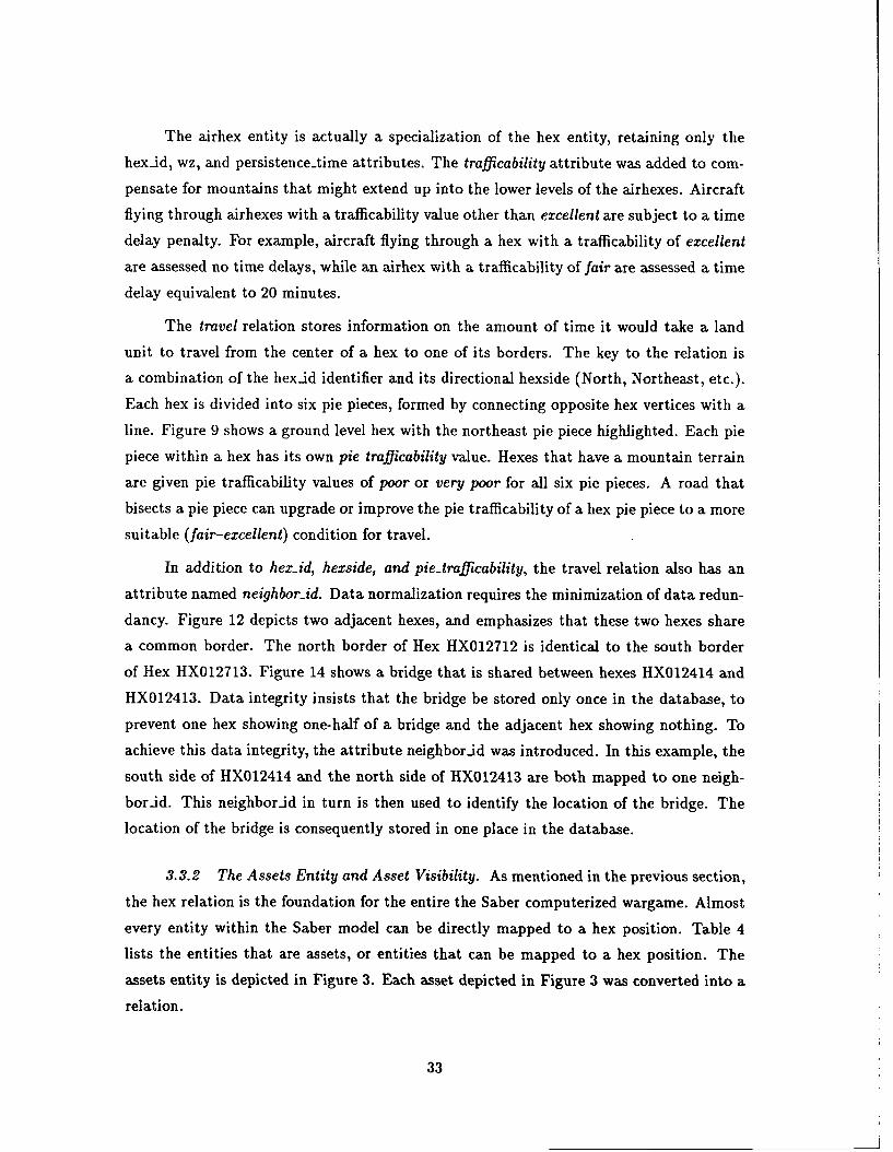
In addition to hex-id, hexside, and pie-trafficability, the travel relation also has an
attribute named neighborid. Data normalization requires the minimization of data redun-
dancy. Figure 12 depicts two adjacent hexes, and emphasizes that these two hexes share
a common border. The north border of Hex HX012712 is identical to the south border
of Hex HX012713. Figure 14 shows a bridge that is shared between hexes HX012414 and
HX012413. Data integrity insists that the bridge be stored only once in the database, to
prevent one hex showing one-half of a bridge and the adjacent hex showing nothing. To
achieve this data integrity, the attribute neighbor-id was introduced. In this example, the
south side of HX012414 and the north side of HX012413 are both mapped to one neigh-
bornd. This neighbor-id in turn is then used to identify the location of the bridge. The
location of the bridge is consequently stored in one place in the database.
3.3.2 The Assets Entity and Asset Visibility. As mentioned in the previous section,
the hex relation is the foundation for the entire the Saber computerized wargame. Almost
every entity within the Saber model can be directly mapped to a hex position. Table 4
lists the entities that are assets, or entities that can be mapped to a hex position. The
assets entity is depicted in Figure 3. Each asset depicted in Figure 3 was converted into a
relation.
33
MThis road segment isRiver X2Dayton } HX012414 North
Bridge
Airbase with 3 runways HX012413
Figure 14. Hex Assets
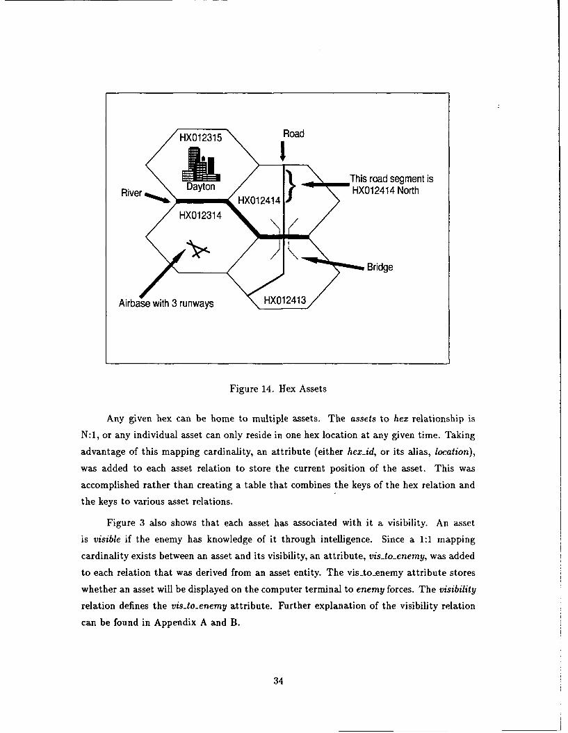
Any given hex can be home to multiple assets. The assets to hex relationship is
N:1, or any individual asset can only reside in one hex location at any given time. Taking
advantage of this mapping cardinality, an attribute (either hex-id, or its alias, location),
was added to each asset relation to store the current position of the asset. This was
accomplished rather than creating a table that combines the keys of the hex relation and
the keys to various asset relations.
Figure 3 also shows that each asset has associated with it a visibility. An asset
is visible if the enemy has knowledge of it through intelligence. Since a 1:1 mapping
cardinality exists between an asset and its visibility, an attribute, vis-to-enemy, was added
to each relation that was derived from an asset entity. The vis-to-enemy attribute stores
whether an asset will be displayed on the computer terminal to enemy forces. The visibility
relation defines the vis-to-enemy attribute. Further explanation of the visibility relation
can be found in Appendix A and B.
34
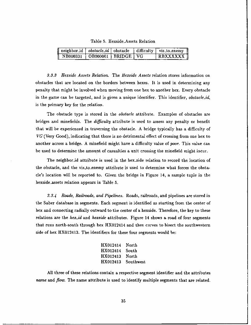
Table 5. Hexside-Assets Relation
neighbor-id obstacle-id obstacle difficulty vis-to-enemyNB000331 OB000001 BRIDGE VG RBXXXXXX
3.3.3 Hexside Assets Relation. The Hexside Assets relation stores information on
obstacles that are located on the borders between hexes. It is used in determining any
penalty that might be involved when moving from one hex to another hex. Every obstacle
in the game can be targeted, and is given a unique identifier. This identifier, obstacle-id,
is the primary key for the relation.
The obstacle type is stored in the obstacle attribute. Examples of obstacles are
bridges and minefields. The difficulty attribute is used to assess any penalty or benefit
that will be experienced in traversing the obstacle. A bridge typically has a difficulty of
VG (Very Good), indicating that there is no detrimental effect of crossing from one hex to
another across a bridge. A minefield might have a difficulty value of poor. This value can
be used to determine the amount of casualties a unit crossing the minefield might incur.
The neighbor-id attribute is used in the hex-side relation to record the location of
the obstacle, and the vis-to-enemy attribute is used to determine what forces the obsta-
cle's location will be reported to. Given the bridge in Figure 14, a sample tuple in the
hexside-assets relation appears in Table 5.
3.3.4 Roads, Railroads, and Pipelines. Roads, railroads, and pipelines are stored in
the Saber database in segments. Each segment is identified as starting from the center of
hex and connecting radially outward to the center of a hexside. Therefore, the key to these
relations are the hexzid and hexside attributes. Figure 14 shows a road of four segments
that runs north-south through hex HX012414 and then curves to bisect the southwestern
side of hex HX012413. The identifiers for these four segments would be:
HX012414 NorthHX012414 SouthHX012413 NorthHX012413 Southwest
All three of these relations contain a respective segment identifier and the attributes
name and flow. The name attribute is used to identify multiple segments that are related.
35
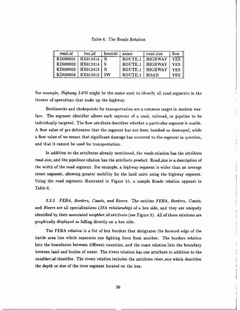
Table 6. The Roads Relation
RD008001 HX012414 N ROUTEI HIGHWAY YES
RD008002 HX012414 S ROUTEI HIGHWAY YESRD008003 HX012413 N ROUTEI HIGHWAY YESRD008004 HX012413 SW ROUTEI ROAD YES
For example, Highway 1-675 might be the name used to identify all road segments in the
theater of operations that make up the highway.
Bottlenecks and chokepoints for transportation are a common target in modern war-
fare. The segment identifier allows each segment of a road, railroad, or pipeline to be
individually targeted. The flow attribute describes whether a particular segment is usable.
A flow value of yes delineates that the segment has not been bombed or destroyed, while
a flow value of no means that significant damage has occurred to the segment in question,
and that it cannot be used for transportation.
In addition to the attributes already mentioned, the roads relation has the attribute
road-size, and the pipelines relation has the attribute product. Road-size is a description of
the width of the road segment. For example, a highway segment is wider than an average
street segment, allowing greater mobility for the land units using the highway segment.
Using the road segments illustrated in Figure 14, a sample Roads relation appears in
Table 6.
3.3.5 FEBA, Borders, Coasts, and Rivers. The entities FEBA, Borders, Coasts,
and Rivers are all specializations (ISA relationship) of a hex side, and they are uniquely
identified by their associated neighbor-id attribute (see Figure 3). All of these relations are
graphically displayed as falling directly on a hex side.
The FEBA relation is a list of hex borders that designates the forward edge of the
battle area line which separates one fighting force from another. The borders relation
lists the boundaries between different countries, and the coast relation lists the boundary
between land and bodies of water. The rivers relation has one attribute in addition to the
neiqhbor-id identifier. The rivers relation includes the attribute river-size which describes
the depth or size of the river segment located on the hex.
36
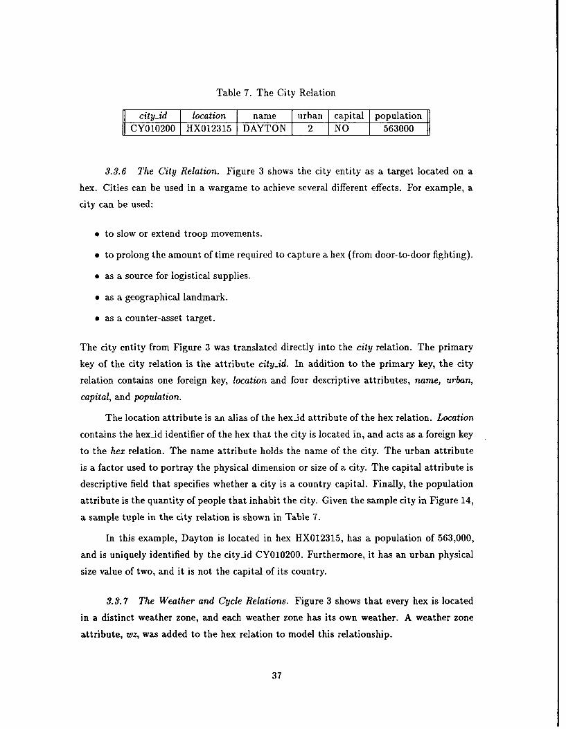
Table 7. The City Relation
fj city-id I location I name I urban capital populationCY010200 HX012315 DAYTON 2 NO 563000
3.3.6 The City Relation. Figure 3 shows the city entity as a target located on a
hex. Cities can be used in a wargame to achieve several different effects. For example, a
city can be used:
" to slow or extend troop movements.
" to prolong the amount of time required to capture a hex (from door-to-door fighting).
" as a source for logistical supplies.
" as a geographical landmark.
" as a counter-asset target.
The city entity from Figure 3 was translated directly into the city relation. The primary
key of the city relation is the attribute city.id. In addition to the primary key, the city
relation contains one foreign key, location and four descriptive attributes, name, urban,
capital, and population.
The location attribute is an alias of the hex-id attribute of the hex relation. Location
contains the hex-id identifier of the hex that the city is located in, and acts as a foreign key
to the hex relation. The name attribute holds the name of the city. The urban attribute
is a factor used to portray the physical dimension or size of a city. The capital attribute is
descriptive field that specifies whether a city is a country capital. Finally, the population
attribute is the quantity of people that inhabit the city. Given the sample city in Figure 14,
a sample tuple in the city relation is shown in Table 7.
In this example, Dayton is located in hex HX012315, has a population of 563,000,
and is uniquely identified by the city-id CY010200. Furthermore, it has an urban physical
size value of two, and it is not the capital of its country.
3.3.7 The Weather and Cycle Relations. Figure 3 shows that every hex is located
in a distinct weather zone, and each weather zone has its own weather. A weather zone
attribute, wz, was added to the hex relation to model this relationship.
37
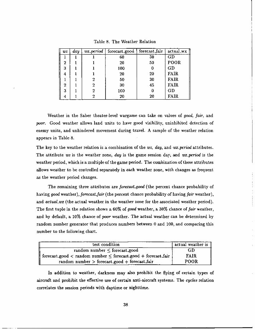
Table 8. The Weather Relation
wz day wx-period forecast-good forecastlair actual-wx1 1 1 60 30 GD2 1 1 20 50 POOR3 1 1 100 0 GD4 1 1 20 20 FAIR1 1 2 50 30 FAIR2 1 2 30 45 FAIR3 1 2 100 0 GD4 1 2 20 20 FAIR
Weather in the Saber theater-level wargame can take on values of good, fair, and
poor. Good weather allows land units to have good visibility, uninhibited detection of
enemy units, and unhindered movement during travel. A sample of the weather relation
appears in Table 8.
The key to the weather relation is a combination of the wz, day, and .wx-period attributes.
The attribute wz is the weather zone, day is the game session day, and wx-period is the
weather period, which is a multiple of the game period. The combination of these attributes
allows weather to be controlled separately in each weather zone, with changes as frequent
as the weather period changes.
The remaining three attributes are forecast-good (the percent chance probability of
having good weather), forecast-fair (the percent chance probability of having fair weather),
and actuaLwx (the actual weather in the weather zone for the associated weather period).
The first tuple in the relation shows a 60% of good weather, a 30% chance of fair weather,
and by default, a 10% chance of poor weather. The actual weather can be determined by
random number generator that produces numbers between 0 and 100, and comparing this
number to the following chart.
test condition actual weather israndom number < forecastgood GD
forecast-good < random number < forecast-good + forecastfair FAIRrandom number > forecast.good + forecast-fair POOR
In addition to weather, darkness may also prohibit the flying of certain types of
aircraft and prohibit the effective use of certain anti-aircraft systems. The cycles relation
correlates the session periods with daytime or nighttime.
38
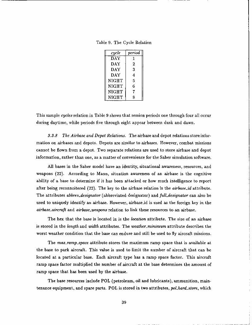
Table 9. The Cycle Relation
cycle periodDAY 1DAY 2DAY 3DAY 4
NIGHT 5NIGHT 6NIGHT 7NIGHT 8
This sample cycles relation in Table 9 shows that session periods one through four all occur
during daytime, while periods five through eight appear between dusk and dawn.
3.3.8 The Airbase and Depot Relations. The airbase and depot relations store infor-
mation on airbases and depots. Depots are similar to airbases. However, combat missions
cannot be flown from a depot. Two separate relations are used to store airbase and depot
information, rather than one, as a matter of convenience for the Saber simulation software.
All bases in the Saber model have an identity, situational awareness, resources, and
weapons (22). According to Mann, situation awareness of an airbase is the cognitive
ability of a base to determine if it has been attacked or how much intelligence to report
after being reconnoitered (22). The key to the airbase relation is the airbase.id attribute.
The attributes abbrev-designator (abbreviated designator) and full-designator can also be
used to uniquely identify an airbase. However, airbaseid is used as the foreign key in the
airbase-aircraft and airbase-weapons relation to link these resources to an airbase.
The hex that the base is located in is the location attribute. The size of an airbase
is stored in the length and width attributes. The weatherminrimum attribute describes the
worst weather condition that the base can endure and still be used to fly aircraft missions.
The max-rampspace attribute stores the maximum ramp space that is available at
the base to park aircraft. This value is used to limit the number of aircraft that can be
located at a particular base. Each aircraft type has a ramp space factor. This aircraft
ramp space factor multiplied the number of aircraft at the base determines the amount of
ramp space that has been used by the airbase.
The base resources include POL (petroleum, oil and lubricants), ammunition, main-
tenance equipment, and spare parts. POL is stored in two attributes, polhard-store, which
39
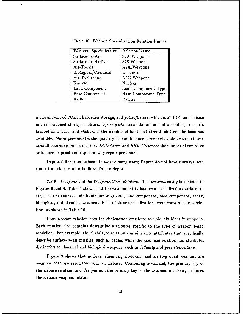
Table 10. Weapon Specialization Relation Names
Weapons Specialization Relation Name
Surface-To-Air S2AWeaponsSurface-To-Surface S2SWeaponsAir-To-Air A2AWeaponsBiological/Chemical ChemicalAir-To-Ground A2GWeaponsNuclear NuclearLand Component LandComponent-TypeBase-Component Base-ComponentTypeRadar Radars
is the amount of POL in hardened storage, and pol-soft-store, which is all POL on the base
not in hardened storage facilities. Spare-parts stores the amount of aircraft spare parts
located on a base, and shelters is the number of hardened aircraft shelters the base has
available. Maint-personnel is the quantity of maintenance personnel available to maintain
aircraft returning from a mission. EODCrews and RRRCrews are the number of explosive
ordinance disposal and rapid runway repair personnel.
Depots differ from airbases in two primary ways; Depots do not have runways, and
combat missions cannot be flown from a depot.
3.3.9 Weapons and the Weapons-Class Relation. The weapons entity is depicted in
Figures 6 and 8. Table 3 shows that the weapon entity has been specialized as surface-to-
air, surface-to-surface, air-to-air, air-to-ground, land component, base component, radar,
biological, and chemical weapons. Each of these specializations were converted to a rela-
tion, as shown in Table 10.
Each weapon relation uses the designation attribute to uniquely identify weapons.
Each relation also contains descriptive attributes specific to the type of weapon being
modelled. For example, the SAM-type relation contains only attributes that specifically
describe surface-to-air missiles, such as range, while the chemical relation has attributes
distinctive to chemical and biological weapons, such as lethality and persistence-time.
Figure 8 shows that nuclear; chemical, air-to-air, and air-to-ground weapons are
weapons that are associated with an airbase. Combining airbase-id, the primary key of
the airbase relation, and designation, the primary key to the weapons relations, produces
the airbase-weapons relation.
40
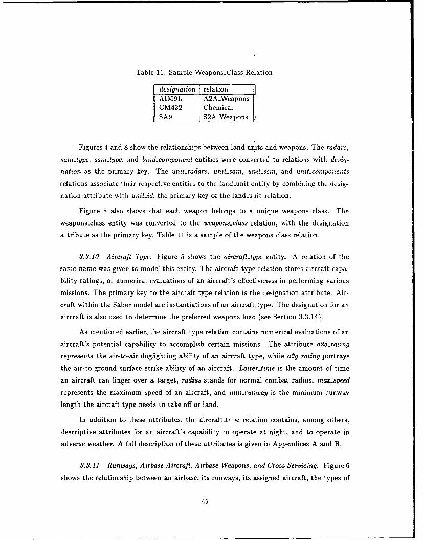
Table 11. Sample Weapons-Class Relation
designation relationAIM9L A2AWeaponsCM432 ChemicalSA9 S2AWeapons
Figures 4 and 8 show the relationships between land units and weapons. The radars,
sam-type, ssm-type, and land-component entities were converted to relations with desig-
nation as the primary key. The unit-radars, unit-sam, unit-ssm, and unit-components
relations associate their respective entitie to the land-unit entity by combining the desig-
nation attribute with unit-id, the primary key of the landu it relation.
Figure 8 also shows that each weapon belongs to a unique weapons class. The
weapons-class entity was converted to the weapons-class relation, with the designation
attribute as the primary key. Table 11 is a sample of the weapons-class relation.
3.3.10 Aircraft Type. Figure 5 shows the aircraft-type entity. A relation of the
same name was given to model this entity. The aircrafttype relation stores aircraft capa-
bility ratings, or numerical evaluations of an aircraft's effectiveness in performing various
missions. The primary key to the aircrafttype relation is the designation attribute. Air-
craft within the Saber model are instantiations of an aircraft-type. The designation for an
aircraft is also used to determine the preferred weapons load (see Section 3.3.14).
As mentioned earlier, the aircrafttype relation contains numerical evaluations of an
aircraft's potential capability to accomplish certain missions. The attribute a2a-rating
represents the air-to-air dogfighting ability of an aircraft type, while a2g-rating portrays
the air-to-ground surface strike ability of an aircraft. Loiter-time is the amount of time
an aircraft can linger over a target, radius stands for normal combat radius, max-speed
represents the maximum speed of an aircraft, and minrunway is the minimum runway
length the aircraft type needs to take off or land.
In addition to these attributes, the aircraft-t--e relation contains, among others,
descriptive attributes for an aircraft's capability to operate at night, and to operate in
adverse weather. A full description of these attributes is given in Appendices A and B.
3.3.11 Runways, Airbase Aircraft, Airbase Weapons, and Cross Servicing. Figure 6
shows the relationship between an airbase, its runways, its assigned aircraft, the types of
41
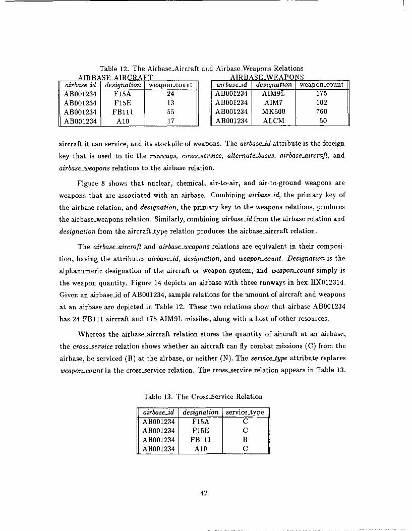
Table 12. The AirbaseAircraft and AirbaseWeapons RelationsAIRBASEAIRCRAFT AIRBASEWEAPONS
airbase-id designation weapon-count airbase-id designation weapon-countAB001234 F15A 24 AB001234 AIM9L 175AB001234 F15E 13 AB001234 AIM7 102AB001234 FB111 55 AB001234 MK500 760AB001234 A10 17 AB001234 ALCM 50
aircraft it can service, and its stockpile of weapons. The airbase-id attribute is the foreign
key that is used to tie the runways, cross-service, alternate-bases, airbase-aircraft, and
airbase-weapons relations to the airbase relation.
Figure 8 shows that nuclear, chemical, air-to-air, and air-to-ground weapons are
weapons that are associated with an airbase. Combining airbaseid, the primary key of
the airbase relation, and designation, the primary key to the weapons relations, produces
the airbase-weapons relation. Similarly, combining airbase-id from the airbase relation and
designation from the aircraft-type relation produces the airbase-aircraft relation.
The airbase-aircraft and airbase-weapons relations are equivalent in their composi-
tion, having the attribu~cs airbase_id, designation, and weapon-count. Designation is the
alphanumeric designation of the aircraft or weapon system, and weapon-count simply is
the weapon quantity. Figure 14 depicts an airbase with three runways in hex HX012314.
Given an airbaseid of AB001234, sample relations for the amount of aircraft and weapons
at an airbase are depicted in Table 12. These two relations show that airbase AB001234
has 24 FB111 aircraft and 175 AIM9L missiles, along with a host of other resources.
Whereas the airbase-aircraft relation stores the quantity of aircraft at an airbase,
the cross-service relation shows whether an aircraft can fly combat missions (C) from the
airbase, be serviced (B) at the airbase, or neither (N). The service-type attribute replaces
weapon-count in the cross-service relation. The cross-service relation appears in Table 13.
Table 13. The Cross-Service Relation
airbase-id designation service-typeAB001234 F15A CAB001234 F15E CAB001234 FB111 BAB001234 A10 C
42
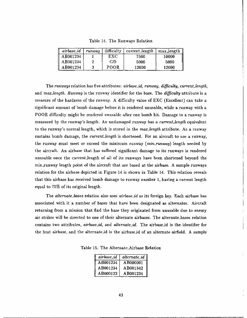
Table 14. The Runways Relation
airbase-id runway difficulty currentiength max-lengthAB001234 1 EXC 7500 10000AB001234 2 GD 5000 5000AB001234 3 POOR 12000 12000
The runways relation has five attributes: airbase-id, runway, difficulty, current-length,
and max-length. Runway is the runway identifier for the base. The difficulty attribute is a
measure of the hardness of the runway. A difficulty value of EXC (Excellent) can take a
significant amount of bomb damage before it is rendered unusable, while a runway with a
POOR difficulty might be rendered unusable after one bomb hit. Damage to a runway is
measured by the runway's length. An undamaged runway has a current-length equivalent
to the runway's normal length, which is stored in the max-length attribute. As a runway
sustains bomb damage, the current-length is shortened. For an aircraft to use a runway,
the runway must meet or exceed the minimum runway (min-runway) length needed by
the aircraft. An airbase that has suffered significant damage to its runways is rendered
unusable once the current-length of all of its runways have been shortened beyond the
min.runway length point of the aircraft that are based at the airbase. A sample runways
relation for the airbase depicted in Figure 14 is shown in Table 14. This relation reveals
that this airbase has received bomb damage to runway number 1, having a current length
equal to 75% of its original length.
The alternate-bases relation also uses airbase-id as its foreign key. Each airbase has
associated with it a number of bases that have been designated as alternates. Aircraft
returning from a mission that find the base they originated from unusable due to enemy
air strikes will be directed to one of their alternate airbases. The alternatebases relation
contains two attributes, airbase-id, and alternateid. The airbase-id is the identifier for
the host airbase, and the alternateid is the airbaseid of an alternate airfield. A sample
Table 15. The Alternate.Airbase Relation
airbase-id alternate-idAB001234 ABOO0001AB001234 AB001342AB000122 AB001234
43
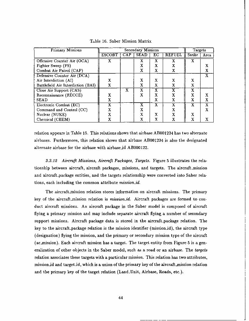
Thble 16. Saber Mission Matrix
Primary Missions _ _ Secondary Missions Targets_I ESCORT CAP SEAD EC REFUEL Strike Area
Offensive Counter Air (OCA) X X X X XFighter Sweep (FS) X X X XCombat Air Patrol (CAP) X X X XDefensive Counter Air (DCA) XAir Interdiction (AI) X X X X XBattlefield Air Interdiction (BAI) X X X X XClose Air Support (CAS) X X X X XReconnaissance (RECCE) X X X X X XSEAD X X X X XElectronic Combat (EC) X X X X X XCommand and Control (CC) X X X XNuclear (NUKE) X X X X XChemical (CHEM) X X X X X X
relation appears in Table 15. This relations shows that airbase AB001234 has two alternate
airbases. Furthermore, this relation shows that airbase AB001234 is also the designated
alternate airbase for the airbase with airbaseid AB000122.
3.3.12 Aircraft Missions, Aircraft Packages, Targets. Figure 5 illustrates the rela-
tionship between aircraft, aircraft packages, missions, and targets. The aircraftmission
and aircraft-package entities, and the targets relationship were converted into Saber rela-
tions, each including the common attribute mission-id.
The aircraft-mission relation stores information on aircraft missions. The primary
key of the aircraft-mission relation is mission-id. Aircraft packages are formed to con-
duct aircraft missions. An aircraft package in the Saber model is composed of aircraft
flying a primary mission and may include separate aircraft flying a number of secondary
support missions. Aircraft package data is stored in the aircraft-package relation. The
key to the aircraft-package relation is the mission identifier (mission-id), the aircraft type
(designation) flying the mission, and the primary or secondary mission type of the aircraft
(acmission). Each aircraft mission has a target. The target entity from Figure 5 is a gen-
eralization of other objects in the Saber model, such as a road or an airbase. The targets
relation associates these targets with a particular mission. This relation has two attributes,
missionid and target-id, which is a union of the primary key of the aircraft-mission relation
and the primary key of the target relation (Land-Unit, Airbase, Roads, etc.).
44
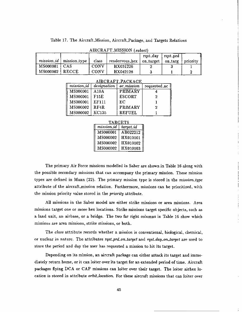
Table 17. The Aircraft-Mission, AircraftPackage, and Targets Relations
AIRCRAFT-MISSION (subset)rqst-day rqst-prd
mission-id mission-type class rendezvous-hex on-target on.targ priorityMS000001 CAS CONV HX031226 2 3 1MS000002 RECCE CONV HX042128 3 1 2
AIRCRAFT-PACKAGEmission-id designation ac-mission requested-acMS000001 A10A PRIMARY 4MS000001 F15E ESCORT 2MS000001 EFll EC 1MS000002 RF4R PRIMARY 2MS000002 KC135 REFUEL 1
TARGETSmission-id target-idMS000001 AB022212MS000002 HX010101MS000002 HX010102MS000002 IHX010103
The primary Air Force missions modelled in Saber are shown in Table 16 along with
the possible secondary missions that can accompany the primary mission. These mission
types are defined in Mann (22). The primary mission type is stored in the mission-type
attribute of the aircraft-mission relation. Furthermore, missions can be prioritized, with
the mission priority value stored in the priority attribute.
All missions in the Saber model are either strike missions or area missions. Area
missions target one or more hex locations. Strike missions target specific objects, such as
a land unit, an airbase, or a bridge. The two far right columns in Table 16 show which
missions are area missions, strike missions, or both.
The class attribute records whether a mission is conventional, biological, chemical,
or nuclear in nature. The attributes rqst-prd-ontarget and rqst-day-on-target are used to
store the period and day the user has requested a mission to hit its target.
Depending on its mission, an aircraft package can either attack its target and imme-
diately return home, or it can loiter over its target for an extended period of time. Aircraft
packages flying DCA or CAP missions can loiter over their target. The loiter airhex lo-
cation is stored in attribute orbit-location. For these aircraft missions that can loiter over
45
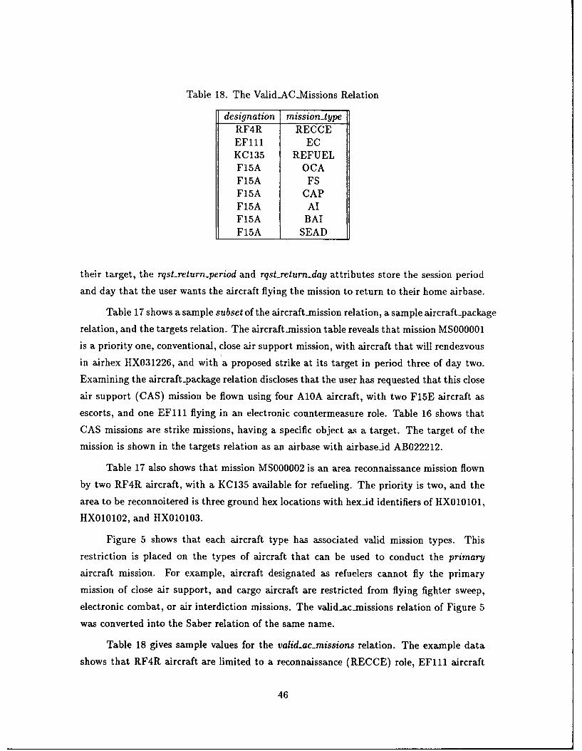
Table 18. The Valid-AClV-issions Relation
designation mission-typeRF4R RECCEEF111 ECKC135 REFUELF15A OCAF15A FSF15A CAPF15A AIF15A BAIF15A SEAD
their target, the rqst-return-period and rqst-returnday attributes store the session period
and day that the user wants the aircraft flying the mission to return to their home airbase.
Table 17 shows a sample subset of the aircraft-mission relation, a sample aircraft-package
relation, and the targets relation. The aircraft-mission table reveals that mission MS000001
is a priority one, conventional, close air support mission, with aircraft that will rendezvous
in airhex HX031226, and with a proposed strike at its target in period three of day two.
Examining the aircraft-package relation discloses that the user has requested that this close
air support (CAS) mission be flown using four A10A aircraft, with two F15E aircraft as
escorts, and one EF111 flying in an electronic countermeasure role. Table 16 shows that
CAS missions are strike missions, having a specific object as a target. The target of the
mission is shown in the targets relation as an airbase with airbase-id AB022212.
Table 17 also shows that mission MS000002 is an area reconnaissance mission flown
by two RF4R aircraft, with a KC135 available for refueling. The priority is two, and the
area to be reconnoitered is three ground hex locations with hexid identifiers of HX010101,
HX010102, and HX010103.
Figure 5 shows that each aircraft type has associated valid mission types. This
restriction is placed on the types of aircraft that can be used to conduct the primary
aircraft mission. For example, aircraft designated as refuelers cannot fly the primary
mission of close air support, and cargo aircraft are restricted from flying fighter sweep,
electronic combat, or air interdiction missions. The valid.ac-missions relation of Figure 5
was converted into the Saber relation of the same name.
Table 18 gives sample values for the valid-ac-missions relation. The example data
shows that RF4R aircraft are limited to a reconnaissance (RECCE) role, EF111 aircraft
46
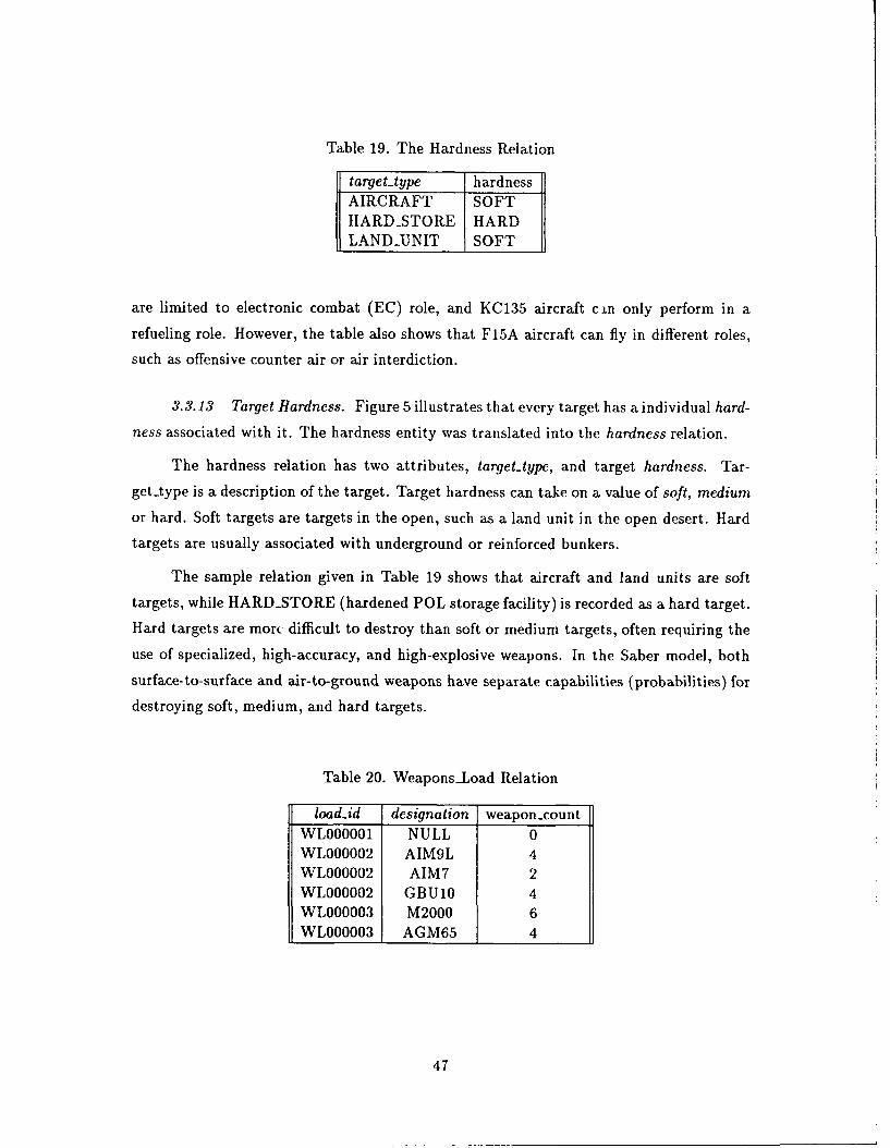
Table 19. The Hardness Relation
target-type hardnessAIRCRAFT SOFTHARD-STORE HARDLAND-UNIT SOFT
are limited to electronic combat (EC) role, and KC135 aircraft cin only perform in a
refueling role. However, the table also shows that F15A aircraft can fly in different roles,
such as offensive counter air or air interdiction.
3.3.13 Target Hardness. Figure 5 illustrates that every target has a individual hard-
ness associated with it. The hardness entity was translated into the hardness relation.
The hardness relation has two attributes, target-type, and target hardness. Tar-get type is a description of the target. Target hardness can take on a value of soft, medium
or hard. Soft targets are targets in the open, such as a land unit in the open desert. Hard
targets are usually associated with underground or reinforced bunkers.
The sample relation given in Table 19 shows that aircraft and land units are soft
targets, while HARD-STORE (hardened POL storage facility) is recorded as a hard target.
Hard targets are mort difficult to destroy than soft or medium targets, often requiring the
use of specialized, high-accuracy, and high-explosive weapons. In the Saber model, both
surface-to-surface and air-to-ground weapons have separate capabilities (probabilities) for
destroying soft, medium, and hard targets.
Table 20. Weapons-Load Relation
load-id designation weapon-countWL000001 NULL 0WL000002 AIM9L 4WL000002 AIM7 2WL000002 GBU10 4WL000003 M2000 6WL000003 AGM65 4
47
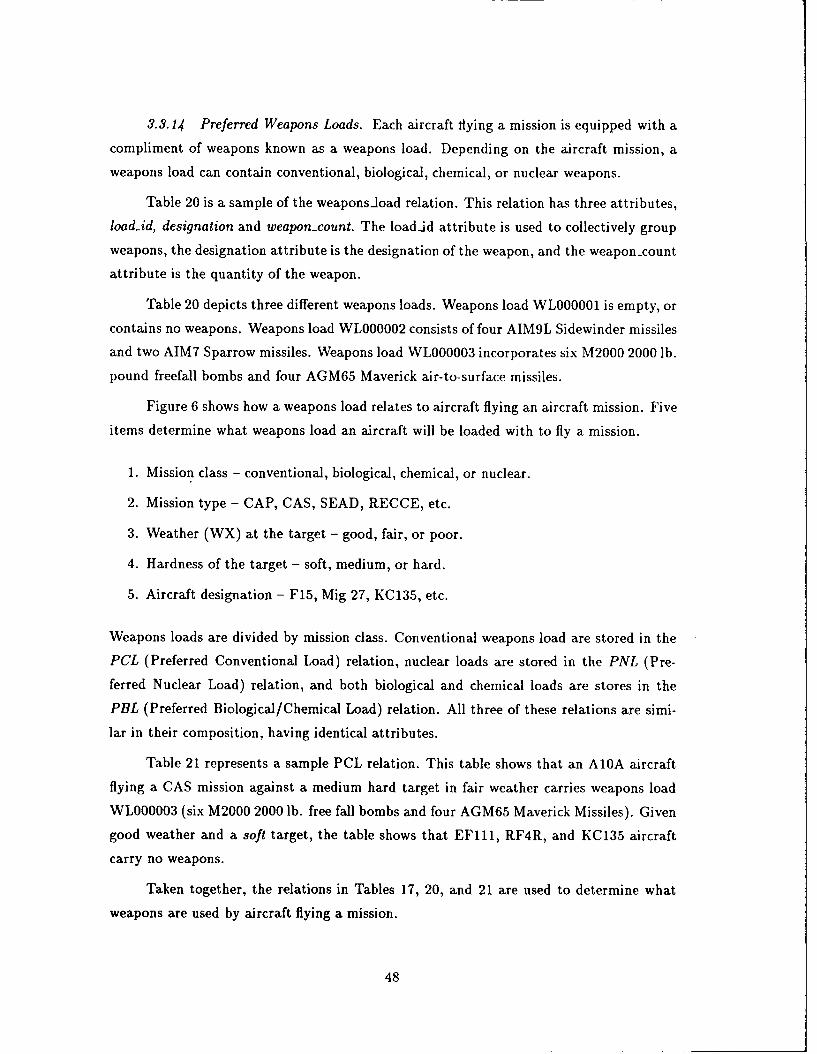
3.3.14 Preferred Weapons Loads. Each aircraft flying a mission is equipped with a
compliment of weapons known as a weapons load. Depending on the aircraft mission, a
weapons load can contain conventional, biological, chemical, or nuclear weapons.
Table 20 is a sample of the weaponsload relation. This relation has three attributes,
loadid, designation and weapon-count. The load-id attribute is used to collectively group
weapons, the designation attribute is the designation of the weapon, and the weapon-count
attribute is the quantity of the weapon.
Table 20 depicts three different weapons loads. Weapons load WL000001 is empty, or
contains no weapons. Weapons load WL000002 consists of four AIM9L Sidewinder missiles
and two AIM7 Sparrow missiles. Weapons load WL000003 incorporates six M2000 2000 lb.
pound freefall bombs and four AGM65 Maverick air-to-surface missiles.
Figure 6 shows how a weapons load relates to aircraft flying an aircraft mission. Five
items determine what weapons load an aircraft will be loaded with to fly a mission.
1. Mission class - conventional, biological, chemical, or nuclear.
2. Mission type - CAP, CAS, SEAD, RECCE, etc.
3. Weather (WX) at the target - good, fair, or poor.
4. Hardness of the target - soft, medium, or hard.
5. Aircraft designation - F15, Mig 27, KC135, etc.
Weapons loads are divided by mission class. Conventional weapons load are stored in the
PCL (Preferred Conventional Load) relation, nuclear loads are stored in the PNL (Pre-
ferred Nuclear Load) relation, and both biological and chemical loads are stores in the
PBL (Preferred Biological/Chemical Load) relation. All three of these relations are simi-
lar in their composition, having identical attributes.
Table 21 represents a sample PCL relation. This table shows that an A1OA aircraft
flying a CAS mission against a medium hard target in fair weather carries weapons load
WL000003 (six M2000 2000 lb. free fall bombs and four AGM65 Maverick Missiles). Given
good weather and a soft target, the table shows that EF111, RF4R, and KC135 aircraft
carry no weapons.
Taken together, the relations in Tables 17, 20, and 21 are used to determine what
weapons are used by aircraft flying a mission.
48
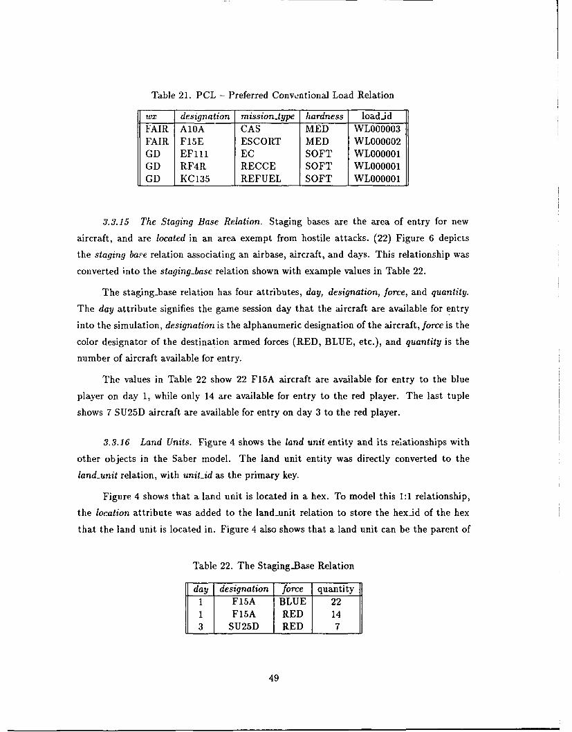
Table 21. PCL - Preferred Conventional Load Relation
wX designation mission-type hardness loadjdFAIR A10A CAS MED WL000003FAIR F15E ESCORT MED WL000002GD EFlll EC SOFT WL000001GD RF4R RECCE SOFT WLOOOO 1GD KC135 REFUEL SOFT WLOOOOO1
3.3.15 The Staging Base Relation. Staging bases are the area of entry for new
aircraft, and are located in an area exempt from hostile attacks. (22) Figure 6 depicts
the staging bare relation associating an airbase, aircraft, and days. This relationship was
converted into the staging-base relation shown with example values in Table 22.
The staging-base relation has four attributes, day, designation, force, and quantity.
The day attribute signifies the game session day that the aircraft are available for entry
into the simulation, designation is the alphanumeric designation of the aircraft, force is the
color designator of the destination armed forces (RED, BLUE, etc.), and quantity is the
number of aircraft available for entry.
The values in Table 22 show 22 F15A aircraft are available for entry to the blue
player on day 1, while only 14 are available for entry to the red player. The last tuple
shows 7 SU25D aircraft are available for entry on day 3 to the red player.
3.3.16 Land Units. Figure 4 shows the land unit entity and its relationships with
other objects in the Saber model. The land unit entity was directly converted to the
land-unit relation, with unit-id as the primary key.
Figure 4 shows that a land unit is located in a hex. To model this 1:1 relationship,
the location attribute was added to the land-unit relation to store the hexid of the hex
that the land unit is located in. Figure 4 also shows that a land unit can be the parent of
Table 22. The Staging-Base Relation
day designation force quantity1 F15A BLUE 221 F15A RED 143 SU25D RED 7
49
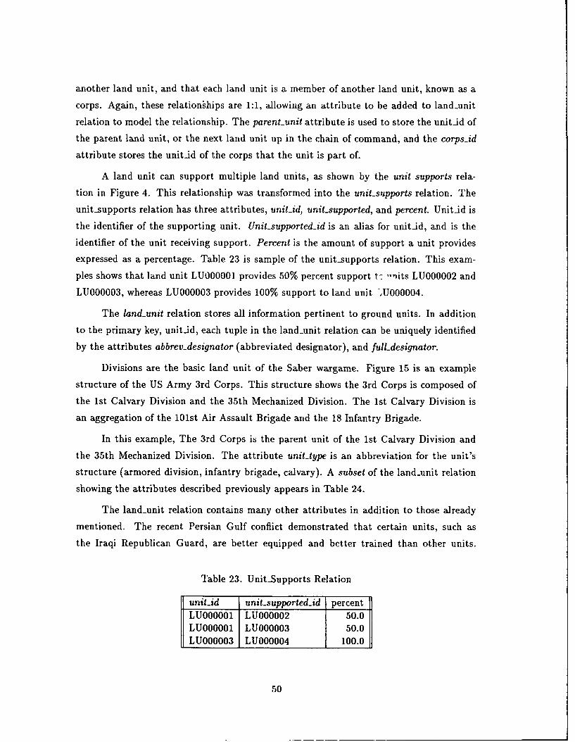
another land unit, and that each land unit is a member of another land unit, known as a
corps. Again, these relationihips are 1:1, allowing an attribute to be added to land-unit
relation to model the relationship. The parent-unit attribute is used to store the unitid of
the parent land unit, or the next land unit up in the chain of command, and the corps-id
attribute stores the unit-id of the corps that the unit is part of.
A land unit can support multiple land units, as shown by the unit supports rela-
tion in Figure 4. This relationship was transformed into the unit-supports relation. The
unit-supports relation has three attributes, unit-id, unit-supported, and percent. Unit-id is
the identifier of the supporting unit. Unit-supported-id is an alias for unitid, and is the
identifier of the unit receiving support. Percent is the amount of support a unit provides
expressed as a percentage. Table 23 is sample of the unit-supports relation. This exam-
ples shows that land unit LU000001 provides 50% percent support t- -nits LU000002 and
LU000003, whereas LU000003 provides 100% support to land unit JU000004.
The land-unit relation stores all information pertinent to ground units. In addition
to the primary key, unitid, each tuple in the land-unit relation can be uniquely identified
by the attributes abbrev.designator (abbreviated designator), and fulLdesignator.
Divisions are the basic land unit of the Saber wargame. Figure 15 is an example
structure of the US Army 3rd Corps. This structure shows the 3rd Corps is composed of
the 1st Calvary Division and the 35th Mechanized Division. The 1st Calvary Division is
an aggregation of the 101st Air Assault Brigade and the 18 Infantry Brigade.
In this example, The 3rd Corps is the parent unit of the 1st Calvary Division and
the 35th Mechanized Division. The attribute unit-type is an abbreviation for the unit's
structure (armored division, infantry brigade, calvary). A subset of the land-unit relation
showing the attributes described previously appears in Table 24.
The land-unit relation contains many other attributes in addition to those already
mentioned. The recent Persian Gulf conflict demonstrated that certain units, such as
the Iraqi Republican Guard, are better equipped and better trained than other units.
Table 23. Unit-Supports Relation
unit-id unit-supported-id percentLUO00001 LUO00002 50.0LUOOOOO1 LUO00003 50.0LUO00003 LUO00004 100.0
50
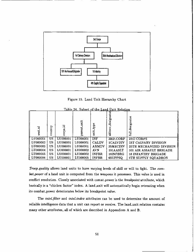
3rd Corps
isjava gDWton &3Mefhaie1 DvWo
Figure 15. Land Unit Hierarchy Chart
Table 24. Subset of the LanUnit Rla~tion0
bO 0
-o
0 0 Cd
LU005USL0001L00 INFB 18NFR 1 INFNRYBIGD
LU000006 IUS ILU000001 LU000005 INFBR 6SUPPSQ 6TH SUPPLY SQUADRON
Troop-quality allows land units to have varying levels of skill or will to fight. The com-
bat-.power of a land unit is computed from the weapons it possesses. This value is used in
conflict resolution. Closely associated with comat-power is the breakpoint attribute, which
basically is a "chicken factor" index. A land-unit will automatically begin retreating when
its combat-power deteriorates below its breakpoint value.
The intel-filter and intel-index attributes can be used to determine the amount of
reliable intelligence data that a unit can report or receive. The land-.unit relation contains
many other attributes, all of which are described in Appendices A and B.
51
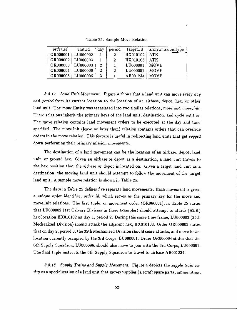
Table 25. Sample Move Relation
order-id unit-id day period target-id army-mission.typeOR000001 LU000002 1 2 HX010102 ATKOR000002 LU000003 1 2 HX010103 ATKOR000003 LU000003 2 1 LU000001 MOVEOR000004 LU000006 2 2 LU000001 MOVEOR000005 LU000006 3 1 AB001234 MOVE
3.3.17 Land Unit Movement. Figure 4 shows that a land unit can move every day
and period from its current location to the location of an airbase, depot, hex, or other
land unit. The move Entity was translated into two similar relations, move and moveInlt.
These relations inherit the primary keys of the land unit, destination, and cycle entities.
The move relation contains land movement orders to be executed at the day and time
specified. The movedlnlt (leave no later than) relation contains orders that can override
orders in the move relation. This feature is useful in redirecting land units that get bogged
down performing their primary mission movements.
The destination of a land movement can be the location of an airbase, depot, land
unit, or ground hex. Given an airbase or depot as a destination, a land unit travels to
the hex position that the airbase or depot is located on. Given a target land unit as a
destination, the moving land unit should attempt to follow the movement of the target
land unit. A sample move relation is shown in Table 25.
The data in Table 25 defines five separate land movements. Each movement is given
a unique order identifier, order id, which serves as the primary key for the move and
moveInlt relations. The first tuple, or movement order (OR000001), in Table 25 states
that LU000002 (1st Calvary Division in these examples) should attempt to attack (ATK)
hex location HX010102 on day 1, period 2. During this same time frame, LU000003 (35th
Mechanized Division) should attack the adjacent hex, HX010103. Order OR000003 states
that on day 2, period 3, the 35th Mechanized Division should cease attacks, and move to the
location currently occupied by the 3rd Corps, LU000001. Order OR000004 states that the
6th Supply Squadron, LU000006, should also move to join with the 3rd Corps, LU000001.
The final tuple instructs the 6th Supply Squadron to travel to airbase AB001234.
3.3.18 Supply Trains and Supply Movement. Figure 4 depicts the supply train en-
tity as a specialization of a land unit that moves supplies (aircraft spare parts, ammunition,
52
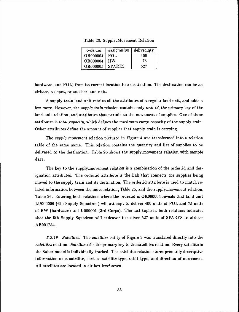
Table 26. Supply-Movement Relation
order.id designation deliver-qty
OR000004 POL 400OR000004 HW 75OR000005 SPARES 527
hardware, and POL) from its current location to a destination. The destination can be an
airbase, a depot, or another land unit.
A supply train land unit retains all the attributes of a regular land unit, and adds a
few more. However, the supply-train relation contains only unit-id, the primary key of the
land-unit relation, and attributes that pertain to the movement of supplies. One of these
attributes is totaLcapacity, which defines the maximum cargo capacity of the supply train.
Other attributes define the amount of supplies that supply train is carrying.
The supply movement relation pictured in Figure 4 was transformed into a relation
table of the same name. This relation contains the quantity and list of supplies to be
delivered to the destination. Table 26 shows the supply_-movement relation with sample
data.
The key to the supply-movement relation is a combination of the orderid and des-
ignation attributes. The orderid attribute is the link that connects the supplies being
moved to the supply train and its destination. The orderid attribute is used to match re-
lated information between the move relation, Table 25, and the supply-movement relation,
Table 26. Entering both relations where the orderid is OR000004 reveals that land unit
LU000006 (6th Supply Squadron) will attempt to deliver 400 units of POL and 75 units
of HW (hardware) to LU000001 (3rd Corps). The last tuple in both relations indicates
that the 6th Supply Squadron will endeavor to deliver 527 units of SPARES to airbase
AB001234.
3.3.19 Satellites. The satellites entity of Figure 3 was translated directly into the
satellites relation. Satellite-id is the primary key to the satellites relation. Every satellite in
the Saber model is individually tracked. The satellites relation stores primarily descriptive
information on a satellite, such as satellite type, orbit type, and direction of movement.
All satellites are located in air hex level seven.
53

3.4 Database Uploading and Downloading
An issue surrounding the design of the Saber theater level wargame was hardware
portability. A goal of the implementation program was to allow Saber to be executed on as
many different hardware platforms as possible by not tieing it to any specific application
program. Therefore, Saber uses the Oracle RDBMS as a repository of data only. Saber
operates totally on data stored in ASCII flat files. This section describes the design and
implementation of the programs that download data from Oracle to ASCII flat files, and
from ASCII flat files to the Oracle RDBMS.
3.4.1 ASCII Flat File Format. The structure of Saber ASCII data files is straight-
forward, and is in format that resembles the relations. Columns represent attributes. Every
tuple is a complete record in a corresponding relation, with each tuple placed on its own
line, separated from other tuples in the relation by a carriage return. Attributes in the
Saber DBMS are defined as one of three data types: character string, integer, or decimal
(floating point). All character string data entries are in uppercase letters only. Appendix B
lists each attribute data type and column width. Attributes that are characters strings
are preceded by one blank space, while integer and decimal attributes are preceded by
two blank spaces. The second blank space that proceeds numeric values is reserved by the
Oracle DBMS for a minus (-) sign for negative values. However, all numeric values in the
Saber DBMS are non-negative, causing a second blank to be output before each numeric
value.
All numeric values, whether integer or decimal, are formatted right-justified, with
leading zeros displayed. The column width of an attribute of type integer can vary from
one to eight digits. All decimal-type attributes are formatted with a column width of 10
characters. These 10 characters are composed of 5 digits with leading zeros followed by
the decimal point followed by 4 significant digits with trailing zeros.
In addition to the data, each ASCII dump file contains two header lines. The first
header line contains the name of the file. The second line is used for column headings.
The column headings are the first characters of the attribute name up to the length of
column width. Column headings longer than the formatted column width are truncated
to the length of the column width. For example, the designation attribute has a column
width of 5 characters, so its column heading in a dump file would be truncated to desig.
54
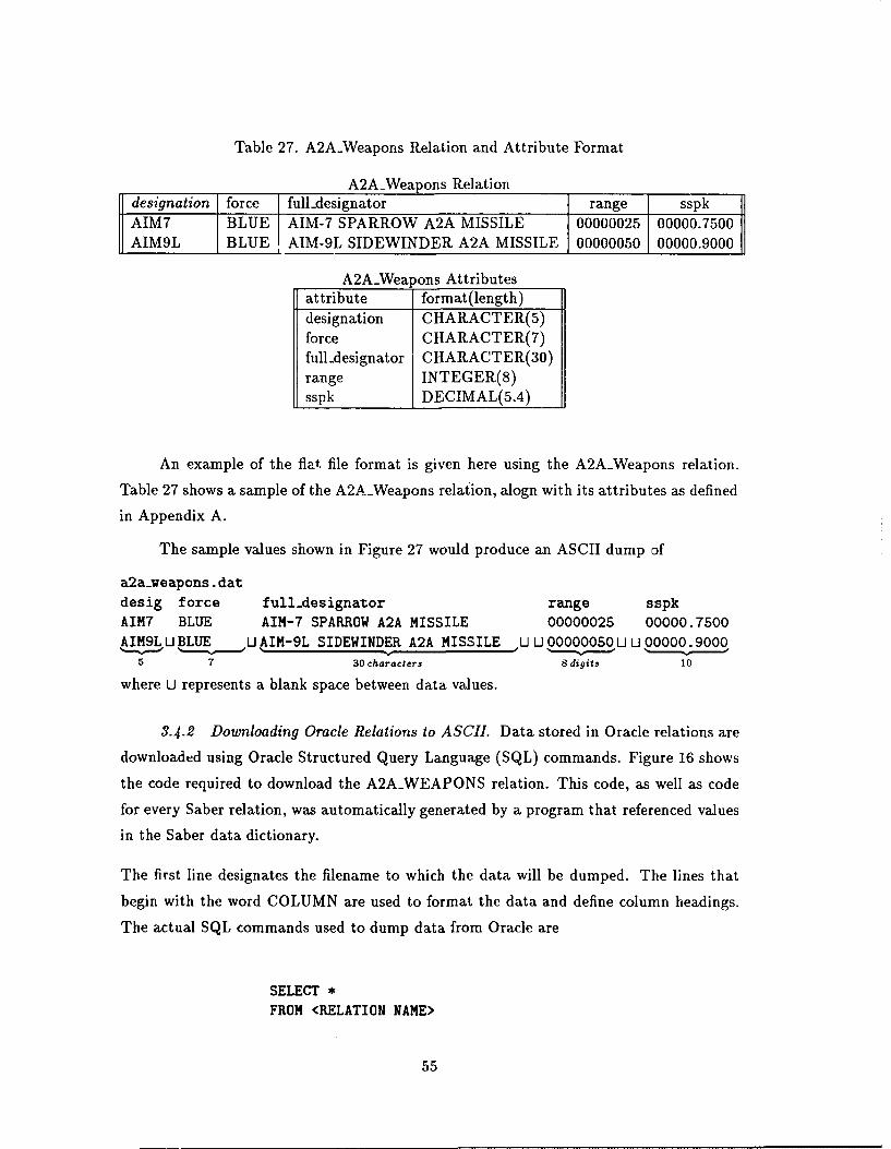
Table 27. A2AWeapons Relation and Attribute Format
A2AWeapons Relationdesignation force full-designator range sspkAIM7 BLUE AIM-7 SPARROW A2A MISSILE 00000025 00000.7500AIM9L BLUE AIM-9L SIDEWINDER A2A MISSILE 00000050 00000.9000
A2AWeapons Attributesattribute format(length)designation CHARACTER(5)force CHARACTER(7)full-designator CHARACTER(30)range INTEGER(8)sspk DECIMAL(5.4)
An example of the flat file format is given here using the A2AWeapons relation.
Table 27 shows a sample of the A2AWeapons relation, alogn with its attributes as defined
in Appendix A.
The sample values shown in Figure 27 would produce an ASCII dump of
a2a.weapons, datdesig force full-designator range sspkAIM7 BLUE AIM-7 SPARROW A2A MISSILE 00000025 00000.7500AIM9L U BLUE U AIM-9L SIDEWINDER A2A MISSILE U U 00000050 U U 00000. 9000
5 7 30 characters 8 digits 10
where U represents a blank space between data values.
3.4.2 Downloading Oracle Relations to ASCII. Data stored in Oracle relations are
downloaded using Oracle Structured Query Language (SQL) commands. Figure 16 shows
the code required to download the A2AWEAPONS relation. This code, as well as code
for every Saber relation, was automatically generated by a program that referenced values
in the Saber data dictionary.
The first line designates the filename to which the data will be dumped. The lines that
begin with the word COLUMN are used to format the data and define column headings.
The actual SQL commands used to dump data from Oracle are
SELECT *
FROM <RELATION NAME>
55
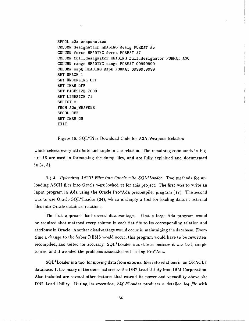
SPOOL a2aweapons two
COLUMN designation HEADING desig FORMAT ABCOLUMN force HEADING force FORMAT A7
COLUMN full-designator HEADING full-designator FORMAT A30
COLUMN range HEADING range FORMAT 09999999COLUMN sspk HEADING sspk FORMAT 09999.9999
SET SPACE 1SET UNDERLINE OFF
SET TERM OFFSET PAGESIZE 7000
SET LINESIZE 71
SELECT *
FROM A2AWEAPONS;
SPOOL OFF
SET TERM ON
EXIT
Figure 16. SQL*Plus Download Code for A2AWeapons Relation
which selects every attribute and tuple in the relation. The remaining commands in Fig-
ure 16 are used in formatting the dump files, and are fully explained and documented
in (4, 5).
3.4.3 Upioading ASCII Files into Oracle with SQL *Loader. Two methods for up-
loading ASCII files into Oracle were looked at for this project. The first was to write an
input program in Ada using the Oracle Pro*Ada precompiler program (17). The second
was to use Oracle SQL*Loader (24), which is simply a tool for loading data in external
files into Oracle database relations.
The first approach had several disadvantages. First a large Ada program would
be required that matched every column in each flat file to its corresponding relation and
attribute in Oracle. Another disadvantage would occur in maintaining the database. Every
time a change to the Saber DBMS would occur, this program would have to be rewritten,
recompiled, and tested for accuracy. SQL*Loader was chosen because it was fast, simple
to use, and it avoided the problems associated with using Pro*Ada.
SQL*Loader is a tool for moving data from external files into relations in an ORACLE
database. It has many of the same features as the DB2 Load Utility from IBM Corporation.
Also included are several other features that extend its power and versatility above the
DB2 Load Utility. During its execution, SQL*Loader produces a detailed log file with
56
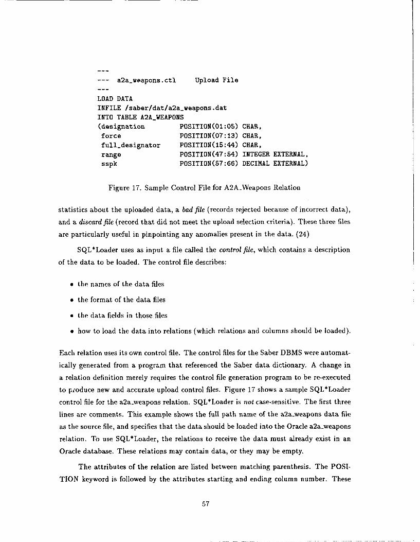
--- a2a-weapons.ctl Upload File
LOAD DATA
INFILE /saber/dat/a2aweapons.dat
INTO TABLE A2AWEAPONS(designation POSITION(01 :05) CHAR,
force POSITION(07:13) CHAR,
full-designator POSITION(15:44) CHAR,
range POSITION(47:54) INTEGER EXTERNAL,
sspk POSITION(57:66) DECIMAL EXTERNAL)
Figure 17. Sample Control File for A2AVeapons Relation
statistics about the uploaded data, a bad file (records rejected because of incorrect data),
and a discard file (record that did not meet the upload selection criteria). These three files
are particularly useful in pinpointing any anomalies present in the data. (24)
SQL*Loader uses as input a file called the control file, which contains a description
of the data to be loaded. The control file describes:
" the names of the data files
* the format of the data files
" the data fields in those files
" how to load the data into relations (which relations and columns should be loaded).
Each relation uses its own control file. The control files for the Saber DBMS were automat-
ically generated from a program that referenced the Saber data dictionary. A change in
a relation definition merely requires the control file generation program to be re-executed
to p;oduce new and accurate upload control files. Figure 17 shows a sample SQL*Loader
control file for the a2a.weapons relation. SQL*Loader is not case-sensitive. The first three
lines are comments. This example shows the full path name of the a2a-weapons data file
as the source file, and specifies that the data should be loaded into the Oracle a2a-weapons
relation. To use SQL*Loader, the relations to receive the data must already exist in an
Oracle database. These relations may contain data, or they may be empty.
The attributes of the relation are listed between matching parenthesis. The POSI-
TION keyword is followed by the attributes starting and ending column number. These
57
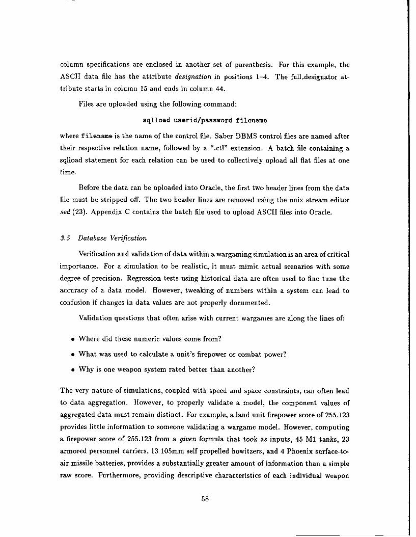
column specifications are enclosed in another set of parenthesis. For this example, the
ASCII data file has the attribute designation in positions 1-4. The full-designator at-
tribute starts in column 15 and ends in column 44.
Files are uploaded using the following command:
sqlload userid/password filename
where filename is the name of the control file. Saber DBMS control files are named after
their respective relation name, followed by a ".ct]" extension. A batch file containing a
sqlload statement for each relation can be used to collectively upload all flat files at one
time.
Before the data can be uploaded into Oracle, the first two header lines from the data
file must be stripped off. The two header lines are removed using the unix stream editor
sed (23). Appendix C contains the batch file used to upload ASCII files into Oracle.
3.5 Database Verification
Verification and validation of data within a wargaming simulation is an area of critical
importance. For a simulation to be realistic, it must mimic actual scenarios with some
degree of precision. Regression tests using historical data are often used to fine tune the
accuracy of a data model. However, tweaking of numbers within a system can lead to
confusion if changes in data values are not properly documented.
Validation questions that often arise with current wargames are along the lines of:
" Where did these numeric values come from?
" What was used to calculate a unit's firepower or combat power?
" Why is one weapon system rated better than another?
The very nature of simulations, coupled with speed and space constraints, can often lead
to data aggregation. However, to properly validate a model, the component values of
aggregated data must remain distinct. For example, a land unit firepower score of 255.123
provides little information to someone validating a wargame model. However, computing
a firepower score of 255.123 from a given formula that took as inputs, 45 MI tanks, 23
armored personnel carriers, 13 105mm self propelled howitzers, and 4 Phoenix surface-to-
air missile batteries, provides a substantially greater amount of information than a simple
raw score. Furthermore, providing descriptive characteristics of each individual weapon
58
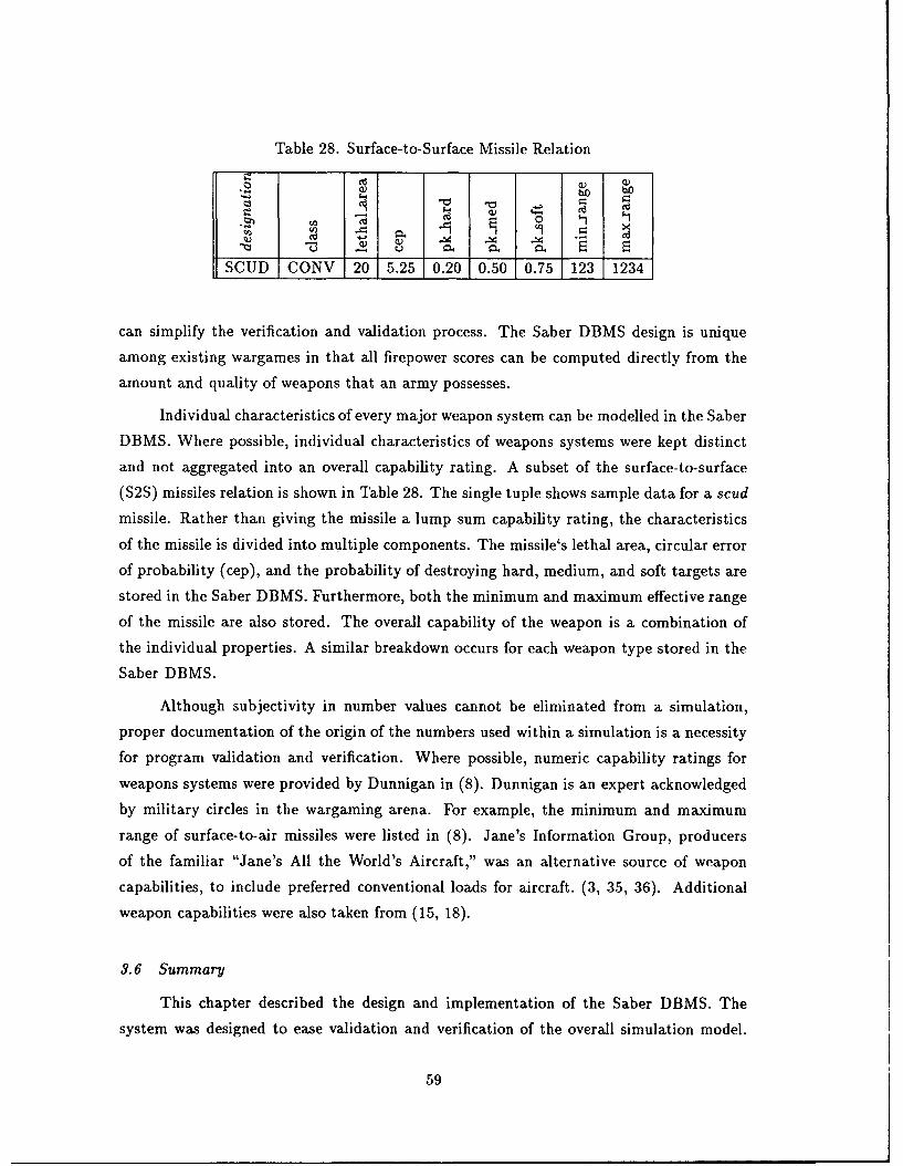
Table 28. Surface-to- Surface Missile Relation
o0
SCUD CONV 20 5.25 0.20 0.50 0.75 1 123 12
can simplify the verification and validation process. The Saber DBMS design is unique
among existing wargames in that all firepower scores can be computed directly from the
amount and quality of weapons that an army possesses.
Individual characteristics of every major weapon system can be modelled in the Saber
DBMS. Where possible, individual characteristics of weapons systems were kept distinct
and not aggregated into an overall capability rating. A subset of the surface-to-surface
(S2S) missiles relation is shown in Table 28. The single tuple shows sample data for a scud
missile. Rather than giving the missile a lump sum capability rating, the characteristics
of the missile is divided into multiple components. The missile's lethal area, circular error
of probability (cep), and the probability of destroying hard, medium, and soft targets are
stored in the Saber DBMS. Furthermore, both the minimum and maximum effective range
of the missile are also stored. The overall capability of the weapon is a combination of
the individual properties. A similar breakdown occurs for each weapon type stored in the
Saber DBMS.
Although subjectivity in number values cannot be eliminated from a simulation,
proper documentation of the origin of the numbers used within a simulation is a necessity
for program validation and verification. Where possible, numeric capability ratings for
weapons systems were provided by Dunnigan in (8). Dunnigan is an expert acknowledged
by military circles in the wargaming arena. For example, the minimum and maximum
range of surface-to-air missiles were listed in (8). Jane's Information Group, producers
of the familiar "Jane's All the World's Aircraft," was an alternative source of weapon
capabilities, to include preferred conventional loads for aircraft. (3, 35, 36). Additional
weapon capabilities were also taken from (15, 18).
3.6 Summary
This chapter described the design and implementation of the Saber DBMS. The
system was designed to ease validation and verification of the overall simulation model.
59

Entity-Relationship diagrams of the Saber model were constructed, iteratively refined, and
then decomposed into relations. Normalization of relations was accomplished to BCNF
level.
The Saber DBMS uses Oracle as a data repository. Data stored in Oracle relations
are downloaded into flat ASCII files using a combination of Structured Query Language
statements and unix stream editing utilities. Data is uploaded from fiat ASCII files via
the Oracle SQL*Loader utility.
The design of the Saber DBMS is unique from other similar applications in that
individual characteristics of individual weapon types are stored. These component values
are then aggregated to combine firepower and combat power ratings. This system simplifies
data verification and validation, and may prove to be beneficial in fine-tuning the overall
simulation.
60
IV. Saber User Interface Implementation
4.1 Overview
This chapter is a description of the unique, original design of the Saber graphical
user-interface (GUI), and its implementation. The chapter begins with background infor-
mation on the Saber interface, which is then followed by principles used in the design and
implementation of the Saber interface. The next section presents a brief description of
the user interface design. The third section is a synopsis of the four areas of user input
defined by Mann (22). This chapter ends with a summary of the user interface design aad
implementation.
The purpose of the user interface is to provide a human interface to the Saber com-
puter simulation program by applying computer graphics techniques. These graphical
techniques, often referred to as a visual interface, have found widespread applications in
man-machine interaction.
The viability of applying a graphical user interface to the Saber is based upon three
factors:
1. The inexperienced or casual user of such a complex application as Saber does not
have or maintain the necessary skills to efficiently utilize the application (21).
2. Military workloads and complexity of computer hardware and wargaming systems
often preclude familiarity with system interfaces (34).
3. The progress and proliferation of high order, user interface programming languages
have promoted the use of GUIs, and have reduced the level of effort required to
produce sufficient and suitable interfaces tailored to specific applications.
New users to wargame simulations are inundated with a variety of obstacles, including
unfamiliar hardware and cryptic command structures, as well as a wide variety of wargam-
ing software systems. In many cases, in-depth training is required before a wargaming
session can commence, which consumes valuable time, resources, and money (34). The
Saber graphical user interface was designed with the goals of allowing fast, easy data entry
for experienced users, without sacrificing user-friendliness for new and inexperienced users.
The design goals of the Saber graphical user interface were:
61
" Fast, easy data entry for experienced users, without sacrificing user-friendliness for
new and inexperienced users.
" Minimize user training requirements through the use of standardized input screens
based on a common template.
" Provide an interface that requires minimal use of external documentation.
" Recognition of information, not recall, is all that is required to properly utilize the
interface.
" Enjoyment in using the system.
4.2 Methodology
The technology to support graphical interfaces has advanced to the point where
most users have come to expect to be able to sit down at a computer and properly exe-
cute a software program with minimal or no references to program documentation. The
mouse, keyboard, high-resolution monitor, and printer are the common elements in micro-
computing that are utilized to enter and extract data from computer systems. Users no
longer are satisfied with traditional direct command entry or menu selection by keyboard,
but prefer to point to a graphically depicted list of possible choices, and click a mouse for
selection.
Apple Computer has developed two helpful sets of principles for the developers of
user interface applications (34). These principles were based on extensive research with
the purpose of assisting developers in generating user-friendly interfaces. The following
general design principles were used in the design and implementation of the Saber user
interface:
1. Metaphors from the real world. Plain and concrete metaphors from the real world
were used, allowing users to apply their expectations to the computer environment.
Visual effects to support the metaphor were used wherever possible. Most computer
users are not experts, but have direct experience in their immediate world. Using
familiar concepts makes users feel comfortable. Figure 18 is a sample list of icons
that can be used to represent four areas of player input in the Saber model.
2. Direct manipulation. Direct manipulation was used to give users a sense of control
over the activities of the computer. Direct manipulation is based on the fact that
people exert physical actions that result in physical feedback. Therefore, moving the
62
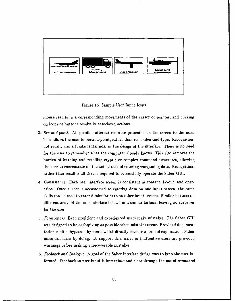
Supply Land UnitAC Movemnnt Movement AC Mission Movement
Figure 18. Sample User Input Icons
mouse results in a corresponding movements of the cursor or pointer, and clicking
on icons or buttons results in associated actions.
3. See-and-point. All possible alternatives were presented on the screen to the user.
This allows the user to see-and-point, rather than remember-and-type. Recognition,
not recall, was a fundamental goal in the design of the interface. There is no need
for the user to remember what the computer already knows. This also removes the
burden of learning and recalling cryptic or complex command structures, allowing
the user to concentrate on the actual task of entering wargaming data. Recognition,
rather than recall is all that is required to successfully operate the Saber GUI.
4. Consistency. Each user interface screen is consistent in content, layout, and oper-
ation. Once a user is accustomed to entering data on one input screen, the same
skills can be used to enter dissimilar data on other input screens. Similar buttons on
different areas of the user interface behave in a similar fashion, leaving no surprises
for the user.
5. Forgiveness. Even proficient and experienced users make mistakes. The Saber GUI
was designed to be as forgiving as possible when mistakes occur. Provided documen-
tation is often bypassed by users, which directly leads to a form of exploration. Saber
users can learn by doing. To support this, naive or inattentive users are provided
warnings before making unrecoverable mistakes.
6. Feedback and Dialogue. A goal of the Saber interface design was to keep the user in-
formed. Feedback to user input is immediate and clear through the use of command
63
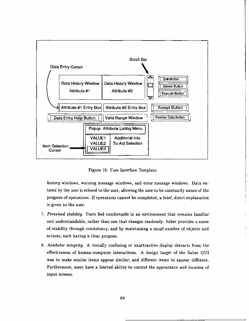
Scroll Bar
Data Entry Cursor
Data History Window Data History Window E3 Edit Butn
Attribute #1 Attribute #2 J DButonSExecute Buttonf
Attribute #1 Entry Box Attribute #2 Entry Box ceputo
Data Entry Help Button Valid Range Window ! Renter DaButon
Popup Attribute Listing Menu
VALUE1 Additional InfoVALUE2 To Aid SelectionItemsoSelection VALUE3
CursorF E3
Figure 19. User Interface Template
history windows, warning message windows, and error message windows. Data en-
tered by the user is echoed to the user, allowing the user to be constantly aware of the
progress of operations. If operations cannot be completed, a brief, direct explanation
is given to the user.
7. Perceived stability. Users feel comfortable in an environment that remains familiar
and understandable, rather than one that changes randomly. Saber provides a sense
of stability through consistency, and by maintaining a small number of objects and
actions, each having a clear purpose.
8. Aesthetic integrity. A visually confusing or unattractive display detracts from the
effectiveness of human-computer interactions. A design target of the Saber GUI
was to make similar items appear similar, and different items to appear different.
Furthermore, users have a limited ability to control the appearance and location of
input screens.
64
4.3 Saber User Interface Design
The Saber data input interface was designed for users having multiple levels of exper-
tise. Fast direct input is available for proficient and experienced users in a format similar
to entry forms supplied by common data base management applications. Varying levels of
(see-and-point) input selection also is available for beginning and novice users.
Figure 19 shows the template used in the design of Saber data input screens. The
use of a single template for all input screens allows consistency and familiarity to be
programmed into the interface. The skills necessary to adequately operate on one data
input screen can be applied to operate all data input screens. An additional goal of
the Saber GUI was to use keyboard keys in a manner consistent with their use in word
processing applications. The <Backspace> and <Del> key can be used to delete unwanted
characters, and the arrow keys can be used for cursor movement.
Each data input screen appears in its own window and is activated by selecting a
controlling icon, such as those shown in Figure 18. This property provides flexibility to
the Saber interface by allowing a user to provide input to multiple areas of the wargame
concurrently, with each area of user input in its own window.
4.3.1 Data Input. A DBMS entry forms usually consists of a fill-in-the-blanks tem-
plate on the computer screen that allows fast input of data items through direct keyboard
entry. The middle of Figure 19 resembles a DBMS data entry form. The template re-
quires the user to enter two different data items. The two fill-in-the-blanks input fields,
attribute #1 entry box, and attribute #2 entry box, are shown in the center of the figure.
Upon entering a data entry window, the user is automatically placed the attribute #1
entry box, although the user can choose the input field they want to type into by pointing
to a field, and then clicking the select button on the mouse. An I-shaped data entry cursor
blinks in the box to mark the typing position. Characters can be typed directly from the
keyboard into the attribute entry box. Hitting the <Return> key enters the information
into the computer, and moves the cursor to the next attribute input field. This method
allows familiar data to be entered into the computer quickly, as they would if they were
being input in a DBMS application.
4.3.2 Help Facilities. Immediately below the input field for attribute #1 is a data
entry help button designed for new and inexperienced users. Selecting the help button
provides a pop-up menu which indexes alternative value selection options. Values can
65
be selected from a list of all the available values with the keyboard or mouse, and their
selection will automatically be entered in the attribute input field. For example, selecting
the data entry help button in Figure 19 produces a pop-up attribute list of three values
that attribute #1 can assume.
In addition to a listing of the available values that an attribute can assume, the values
of certain attributes can be displayed graphically in a separate window. The user selects
the value by clicking the mouse over the symbol that represents the desired data value. The
purpose behind listing all available values is to place an emphasis on recognition, and not
recollection of information. The interface is designed to aid the user in any way possible,
permitting the user to focus on the wargame application.
4.3.3 Feedback, Dialogue, and Warning Messages. Several events occur once an
item is entered into an input field:
1. Error Checking - All items entered are immediately verified as to their validity. Users
are notified of input errors, and the I-shaped cursor is once again placed in the input
field.
2. Error Correction - All items entered are automatically converted to uppercase. Fur-
thermore, any illegal characters that could not possibly be part of a valid input
string, such as a space, ampersand, or apostrophe, are automatically removed by the
interface. The modified input string is then checked for validity against a list of all
possible values.
Figure 20 shows valid input strings for a text input field designed to accept airbase
identifier input. The input field in Figure 20 will accept either the abbreviated des-
ignator, abbrev.designator, or some form of the airbase.id attribute. In this example,
the abbrev-designator has a value of TAEGU and the airbaseid attribute has a value
of ABOO0800. Each of the entries in Figure 20 are automatically corrected by the user
interface without an error message being generated. This allows the user to continue
typing input without interruption and without having to delete illegal characters.
Figure 20 also shows sample input strings accepted for aircraft designation entries.
A modified input string without invalid characters that does not match any valid
value can be input to a spell checking routine to further assist the user. For example,
an input of Eegle would automatically be corrected to EAGLE without generating
an error message, and without requiring the user to edit the input data. These forms
of error correction maximize the rate of data entry from the keyboard.
66
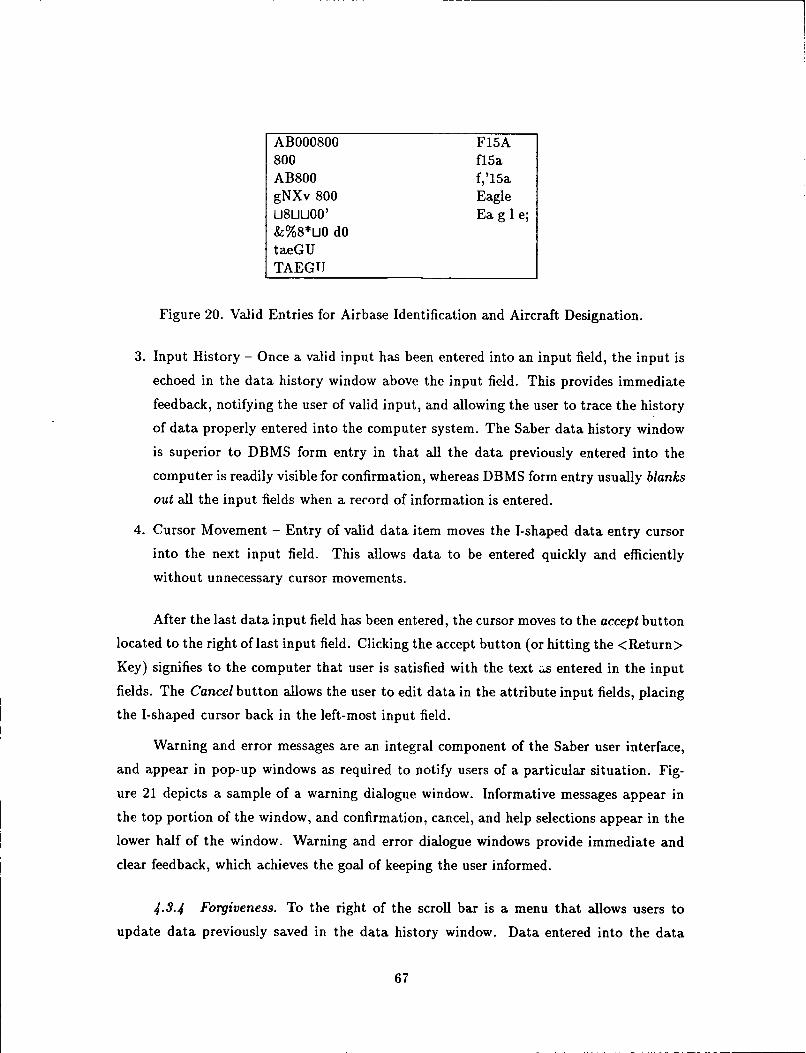
ABOO0800 F15A800 fl5aAB800 f,'15agNXv 800 EagleU8UU00' Ea g 1 e;&%8*U0 dOtaeGUTAEGTI
Figure 20. Valid Entries for Airbase Identification and Aircraft Designation.
3. Input History - Once a valid input has been entered into an input field, the input is
echoed in the data history window above the input field. This provides immediate
feedback, notifying the user of valid input, and allowing the user to trace the history
of data properly entered into the computer system. The Saber data history window
is superior to DBMS form entry in that all the data previously entered into the
computer is readily visible for confirmation, whereas DBMS form entry usually blanks
out all the input fields when a record of information is entered.
4. Cursor Movement - Entry of valid data item moves the I-shaped data entry cursor
into the next input field. This allows data to be entered quickly and efficiently
without unnecessary cursor movements.
After the last data input field has been entered, the cursor moves to the accept button
located to the right of last input field. Clicking the accept button (or hitting the <Return>
Key) signifies to the computer that user is satisfied with the text as entered in the input
fields. The Cancel button allows the user to edit data in the attribute input fields, placing
the I-shaped cursor back in the left-most input field.
Warning and error messages are an integral component of the Saber user interface,
and appear in pop-up windows as required to notify users of a particular situation. Fig-
ure 21 depicts a sample of a warning dialogue window. Informative messages appear in
the top portion of the window, and confirmation, cancel, and help selections appear in the
lower half of the window. Warning and error dialogue windows provide immediate and
clear feedback, which achieves the goal of keeping the user informed.
4.3.4 Forgiveness. To the right of the scroll bar is a menu that allows users to
update data previously saved in the data history window. Data entered into the data
67
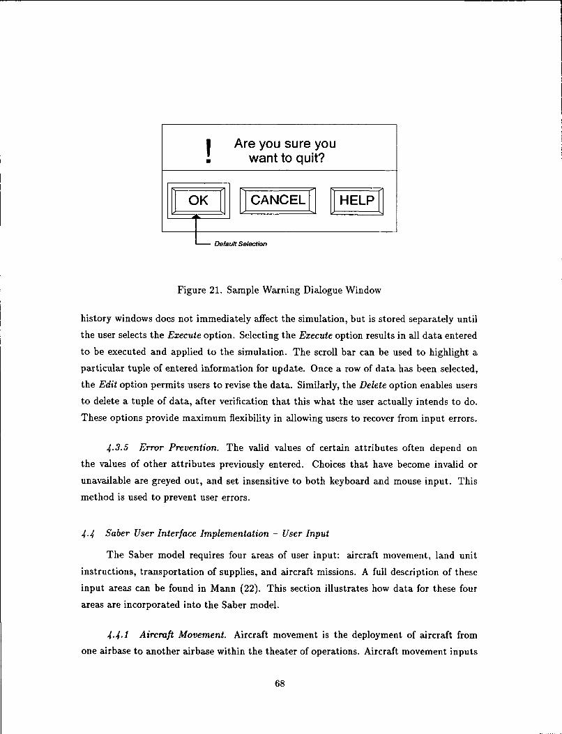
Are you sure youwant to quit?
E ~ CANCE , EL.Pi
Default Selection
Figure 21. Sample Warning Dialogue Window
history windows does not immediately affect the simulation, but is stored separately until
the user selects the Execute option. Selecting the Execute option results in all data entered
to be executed and applied to the simulation. The scroll bar can be used to highlight a
particular tuple of entered information for update. Once a row of data has been selected,
the Edit option permits users to revise the data. Similarly, the Delete option enables users
to delete a tuple of data, after verification that this what the user actually intends to do.
These options provide maximum flexibility in allowing users to recover from input errors.
4.3.5 Error Prevention. The valid values of certain attributes often depend on
the values of other attributes previously entered. Choices that have become invalid or
unavailable are greyed out, and set insensitive to both keyboard and mouse input. This
method is used to prevent user errors.
4.4 Saber User Interface Implementation - User Input
The Saber model requires four areas of user input: aircraft movement, land unit
instructions, transportation of supplies, and aircraft missions. A full description of these
input areas can be found in Mann (22). This section illustrates how data for these four
areas are incorporated into the Saber model.
4.4.1 Aircraft Movement. Aircraft movement is the deployment of aircraft from
one airbase to another airbase within the theater of operations. Aircraft movement inputs
68
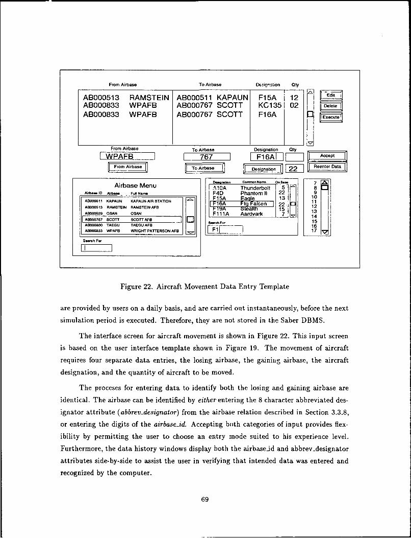
From Airbase To Airbase D16si--tion Qty
AB000513 RAMSTEIN ABOO0511 KAPAUN F15A 12AB000833 WPAFB AB000767 SCOTT KC1 35 02AB000833 WPAFB AB000767 SCOTT F1 6A
From Airbase To Airbase Designation Qty
WPAFB 767 F16AI -- p
FromAiTose Designation F2j Reen ta
DeMson Coon. N.l On B.Airbase Menu IA Thunderbolt 5 8Arba-.ID AJ..r FullNam - F4D Phantom 11 22 9AB000511 KAPAUN KAPAUN AIR STATION I1 5AF a 213 1210
AB000513 RAMSTEIN RAMSTEIN AFB 12FA wea 15 13A8000529 OSAN OSAN F111A Aardvark 14A9000767 SCOTr SCOTT AFB e Fo.: 15AGO00800 TAEGU TAEGU AFB ] 16AB000833 WPAFB WRIGHT PATTERSON AFB F1 17
Sewch For
Figure 22. Aircraft Movement Data Entry Template
are provided by users on a daily basis, and are carried out instantaneously, before the next
simulation period is executed. Therefore, they are not stored in the Saber DBMS.
The interface screen for aircraft movement is shown in Figure 22. This input screen
is based on the user interface template shown in Figure 19. The movement of aircraft
requires four separate data entries, the losing airbase, the gainilig airbase, the aircraft
designation, and the quantity of aircraft to be moved.
The proceses for entering data to identify both the losing and gaining airbase are
identical. The airbase can be identified by either entering the 8 character abbreviated des-
ignator attribute (abbrev-designator) from the airbase relation described in Section 3.3.8,
or entering the digits of the airbase.id. Accepting both categories of input provides flex-
ibility by permitting the user to choose an entry mode suited to his experience level.
Furthermore, the data history windows display both the airbaseid and abbrev-designator
attributes side-by-side to assist the user in verifying that intended data was entered and
recognized by the computer.
69
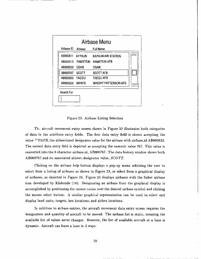
Airbase MenuAirbase ID Airbase Full Name
ABOO0511 KPPAUN KAPAUN AIR STATION
ABOO0513 RAMSTEIN RAMSTEIN AFB
AB000529 OSAN OSAN
AB000767 SCOTT SCOT AFBABOO0800 TAEGU TAEGU AFBAB000833 WPAFB WRIGHT PATTERSON AFB
Search For
Figure 23. Airbase Listing Selection
Th.= aircraft movement entry screen shown in Figure 22 illustrates both categories
of data in the attribute entry fields. The first data entry field is shown accepting the
value "PAFB, the abbreviated designator value for the airbase with airbase-id AB000833.
The second data entry field is depicted as accepting the numeric value 767. This value is
converted into the 8 character airbase-id, AB000767. The data history window shows both
AB000767 and its associated abbrev-designator value, SCOTT.
Clicking on the airbase help button displays a pop-up menu soliciting the user to
select from a listing of airbases as shown in Figure 23, or select from a graphical display
of airbases, as depicted in Figure 24. Figure 24 displays airbases with the Saber airbase
icon developed by Klabunde (16). Designating an airbase from the graphical display is
accomplished by positioning the mouse cursor over the desired airbase symbol and clicking
the mouse select button. A similar graphical representation can be used to select and
display land units, targets, hex locations, and airhex locations.
In addition to airbase entries, the aircraft movement data entry screen requires the
designation and quantity of aircraft to be moved. The airbase list is static, meaning the
available list of values never changes. However, the list of available aircraft at a base is
dynamic. Aircraft can leave a base in 3 ways:
70
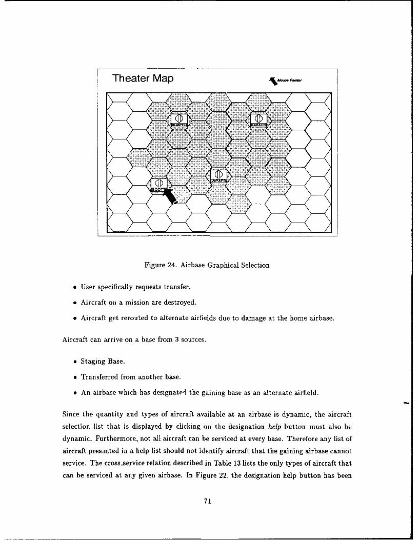
Theater Map
Figure 24. Airbase Graphical Selection
* User specifically requests transfer.
* Aircraft on a mission are destroyed.
* Aircraft get rerouted to alternate airfields due to damage at the home airbase.
Aircraft can arrive on a base from 3 sources.
* Staging Base.
* Transferred from another base.
* An airbase which has designated the gaining base as an alternate airfield.
Since the quantity and types of aircraft available at an airbase is dynamic, the aircraft
selection list that is displayed by clicking on the designation help button must also be
dynamic. Furthermore, not all aircraft can be serviced at every base. Therefore any list of
aircraft presented in a help list should not identify aircraft that the gaining airbase cannot
service. The cross~service relation described in Table 13 lists the only types of aircraft that
can be serviced at any given airbase. In Figure 22, the designation help button has been
71
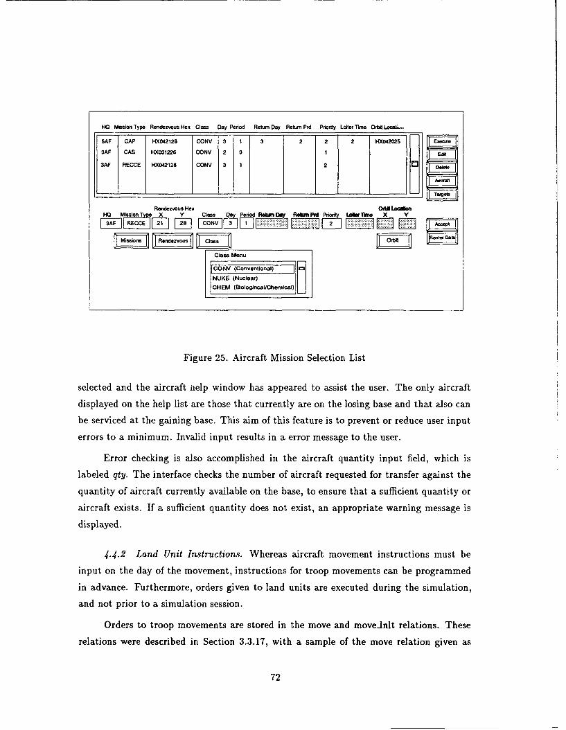
HO Mission Type Rendezvous Hex Class Day Period Return Day Return Prd Priority Loiter Tkme Orbil Low"a.,
5AF CAP HX042128 CONV 3 1 3 2 2 2 HX042025
3AF CAS HX031226 CONV 2 3 1
3AF RECCE HX042128 CONV 3 1 2 03
Rendezvous Hex OrbillLacmHO Mission T7 X Y Class Da Period Rekf ay Rekan Pid UAWe Th aX Y
3AF M2 CONV j-] f i1]
Class Menu
CONV (Conventional)
NUKE (Nuclear)CHEM (BologincalChemica) Li
Figure 25. Aircraft Mission Selection List
selected and the aircraft iielp window has appeared to assist the user. The only aircraft
displayed on the help list are those that currently are on the losing base and that also can
be serviced at the gaining base. This aim of this feature is to prevent or reduce user input
errors to a minimum. Invalid input results in a error message to the user.
Error checking is also accomplished in the aircraft quantity input field, which is
labeled qty. The interface checks the number of aircraft requested for transfer against the
quantity of aircraft currently available on the base, to ensure that a sufficient quantity or
aircraft exists. If a sufficient quantity does not exist, an appropriate warning message is
displayed.
4.4.2 Land Unit Instructions. Whereas aircraft movement instructions must be
input on the day of the movement, instructions for troop movements can be programmed
in advance. Furthermore, orders given to land units are executed during the simulation,
and not prior to a simulation session.
Orders to troop movements are stored in the move and movednlt relations. These
relations were described in Section 3.3.17, with a sample of the move relation given as
72
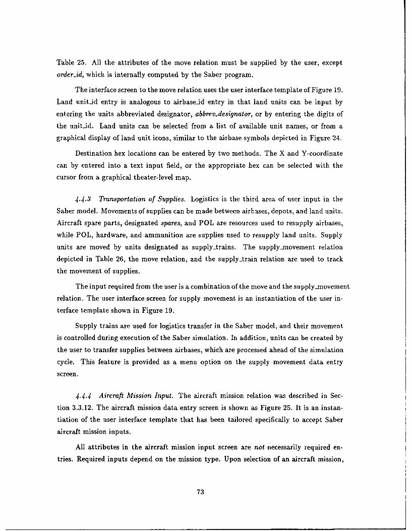
Table 25. All the attributes of the move relation must be supplied by the user, except
order-id, which is internally computed by the Saber program.
The interface screen to the move relation uses the user interface template of Figure 19.
Land unitid entry is analogous to airbaseid entry in that land units can be input by
entering the units abbreviated designator, abbrevdesignator, or by entering the digits of
the unitid. Land units can be selected from a list of available unit names, or from a
graphical display of land unit icons, similar to the airbase symbols depicted in Figure 24.
Destination hex locations can be entered by two methods. The X and Y-coordinate
can by entered into a text input field, or the appropriate hex can be selected with the
cursor from a graphical theater-level map.
4.4.3 Transportation of Supplies. Logistics is the third area of user input in the
Saber model. Movements of supplies can be made between airbases, depots, and land units.
Aircraft spare parts, designated spares, and POL are resources used to resupply airbases,
while POL, hardware, and ammunition are supplies used to resupply land units. Supply
units are moved by units designated as supply.trains. The supply-movement relation
depicted in Table 26, the move relation, and the supplytrain relation are used to track
the movement of supplies.
The input required from the user is a combination of the move and the supply-movement
relation. The user interface screen for supply movement is an instantiation of the user in-
terface template shown in Figure 19.
Supply trains are used for logistics transfer in the Saber model, and their movement
is controlled during execution of the Saber simulation. In addition, units can be created by
the user to transfer supplies between airbases, which are processed ahead of the simulation
cycle. This feature is provided as a menu option on the supply movement data entry
screen.
4.4.4 Aircraft Mission Input. The aircraft mission relation was described in Sec-
tion 3.3.12. The aircraft mission data entry screen is shown as Figure 25. It is an instan-
tiation of the user interface template that has been tailored specifically to accept Saber
aircraft mission inputs.
All attributes in the aircraft mission input screen are not necessarily required en-
tries. Required inputs depend on the mission type. Upon selection of an aircraft mission,
73
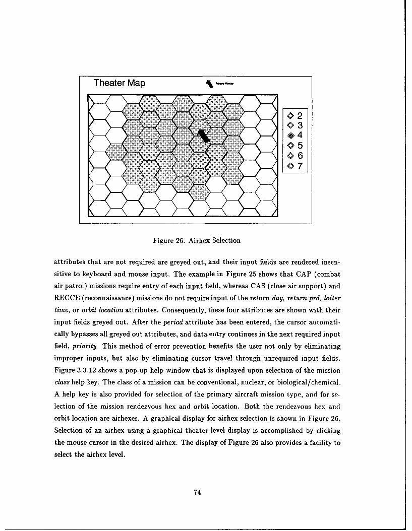
Theater Map
Figure 26. Airhex Selection
attributes that are not required are greyed out, and their input fields are rendered insen-
sitive to keyboard and mouse input. The example in Figure 25 shows that CAP (combat
air patrol) missions require entry of each input field, whereas GAS (close air support) and
RECCE (reconnaissance) missions do not require input of the return day, return prd, loiter
time, or orbit location attributes. Consequently, these four attributes are shown with their
input fields greyed out. After the period attribute has been entered, the cursor automati-
cally bypasses all greyed out attributes, and data entry continues in the next required input
field, priority. This method of error prevention benefits the user not only by eliminating
improper inputs, but also by eliminating cursor travel through unrequired input fields.
Figure 3.3.12 shows a pop-up help window that is displayed upon selection of the mission
class help key. The class of a mission can be conventional, nuclear, or biological/chemical.
A help key is also provided for selection of the primary aircraft mission type, and for se-
lection of the mission rendezvous hex and orbit location. Both the rendezvous hex and
orbit location are airhexes. A graphical display for airhex selection is shown in Figure 26.
Selection of an airhex using a graphical theater level display is accomplished by clicking
the mouse cursor in the desired airhex. The display of Figure 26 also provides a facility to
select the airhex level.
74
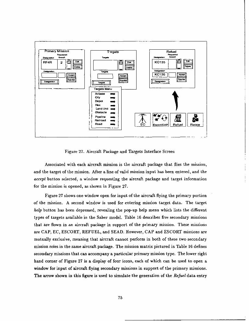
Primary Mission Tirgets r RefuelR.q-td R
0...gn.n Al..ft T e O U n A.-t
D~mgnonTrie ,,
Targets MenuAirbase me*city ,E0DepotHex =No,Land Unit *
ObstaclePipeline Re eRailroadRoad EC EscortCAP Refuel
Figure 27. Aircraft Package and Targets Interface Screen
Associated with each aircraft mission is the aircraft package that flies the mission,
and the target of the mission. After a line of valid mission input has been entered, and the
accept button selected, a window requesting the aircraft package and target information
for the mission is opened, as shown in Figure 27.
Figure 27 shows one window open for input of the aircraft flying the primary portion
of the mission. A second window is used for entering mission target data. The target
help button has been depressed, revealing the pop-up help menu which lists the different
types of targets available in the Saber model. Table 16 describes five secondary missions
that are flown in an aircraft package in support of the primary mission. These missions
are CAP, EC, ESCORT, REFUEL, and SEAD. However, CAP and ESCORT missions are
mutually exclusive, meaning that aircraft cannot perform in both of these two secondary
mission roles in the same aircraft package. The mission matrix pictured in Table 16 defines
secondary missions that can accompany a particular primary mission type. The lower right
hand corner of Figure 27 is a display of four icons, each of which can be used to open a
window for input of aircraft flying secondary missions in support of the primary missions.
The arrow shown in this figure is used to simulate the generation of the Refuel data entry
75

window from selection of the refuel icon. Normally, icons disappear when the window it
controls is opened. However, the refuel icon is shown here for illustrative purposes only.
CAP and ESCORT missions are mutually exclusive. Therefore, one icon can be used
to control both types of input. Only windows to secondary missions that will used in a
particular aircraft package need to be opened by the user. Therefore, placing secondary
missions in separate windows reduces screen clutter, and allows the user to customize the
layout of the aircraft package input screen.
Two additional buttons not found in the user interface template appear in the aircraft
mission input screen. These buttons, labeled aircraft and target, appear with the data
history delete and edit buttons, and are used to update the aircraft packages and targets
of a previously entered mission input tuple that appears in the data history window.
4.5 X Window Implementation
The Saber user interface was implemented using the X Window System and Motif.
Motif is a graphical interface, a style guide for providing application consistency, a pro-
grammer's toolkit library, and a window manager (12). Several sources of documentation
cover both the Motif toolkit and the X Window system, including (2, 12, 13, 29, 39).
The use of Motif to implement the Saber user interface was a design constraint,
as indicated in Section 1.4. However, there are several advantages for using Motif and
X-Windows as the interface platform for the Saber Wargame.
1. Motif provides a standard interface with a consistent look and feel. Users can spend
less time learning new Motif applications, since the knowledge of using one Motif
application can be transferred to other applications.
2. Motif provides a very high-level object-oriented library. Extremely complex graphical
programs can be generated with a very small amount of code. The Motif toolkit
allows the reuse of functions specified in the toolkit, consequently saving program
development time and effort.
3. Motif is based upon X Windows, which has been adopted as one computer industry
standard, and allows programs to be executed on a variety of different platforms.
(12)
The Motif programmers library consists of a variety of widgets. A widget is an object
that provides a user interface abstraction (12). Definitions of widgets are not described in
76
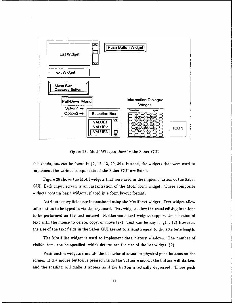
_nPush But et
List Widget E
Text Widget
Menu BaCascade Button
Pull-Down Menu Information DialogueOption1 * _,1 M, Widget
Option2 , Selection Box \J
VALUE2 ICONVALUE3 L
Figure 28. Motif Widgets Used in the Saber GUI
this thesis, but can be found in (2, 12, 13, 29, 39). Instead, the widgets that were used to
implement the various components of the Saber GUI are listed.
Figure 28 shows the Motif widgets that were used in the implementation of the Saber
GUI. Each input screen is an instantiation of the Motif form widget. These composite
widgets contain basic widgets, placed in a form layout format.
Attribute entry fields are instantiated using the Motif text widget. Text widget allow
information to be typed in via the keyboard. Text widgets allow the usual editing functions
to be performed on the text entered. Furthermore, text widgets support the selection of
text with the mouse to delete, copy, or move text. Text can be any length. (2) However,
the size of the text fields in the Saber GUI are set to a length equal to the attribute length.
The Motif list widget is used to implement data history windows. The number of
visible items can be specified, which determines the size of the list widget. (2)
Push button widgets simulate the behavior of actual or physical push buttons on the
screen. If the mouse button is pressed inside the button window, the button will darken,
and the shading will make it appear as if the button is actually depressed. These push
77
button widgets are used in the Saber GUI to access pop-up help menus, and to perform
operations, such as editing and deleting data. (2)
Help menus in the Saber GUI are normally implemented using cascade buttons and
pull-down menus. Pull-down help menus are activated by pressing the cascade button
widget associated with the help menu bar. Cascade buttons in the menu bar are similar
to push buttons, except that they do not normally display a shadow. When the cascade
button is depressed, its shading changes, and its associated pull-down menu is displayed.
(2)
Motif list widgets are used to select one or more strings from an arbitrary list of
items. Scrolled list widgets and selection box widgets are specializations of the list widget.
These widgets are used in Saber to display to the user all of his possible choices.
Graphical displays were implemented with an information dialogue widget. These
high-level widgets are actually aggregations of several smaller level widgets. These graph-
ical selection widgets were developed and documented by Klabunde in (16).
Finally, icons are used in the Saber GUI in a standardized manner consistent to
their use in common graphical user interface applications. Icons are used in the control of
opening and closing windows.
4.6 Summary
The Saber graphical user interface has been designed to accomnodate users with
different levels of computer expertise. Fast keyboard entry in a format similar to DBMS
entry forms is provided for experienced users, while selection lists and graphical displays
are used to assist novice and inexperienced users of the Saber wargame.
The design goals of the Saber graphical user interface were:
" Fast, easy data entry for experienced users, without sacrificing user-friendliness for
new and inexperienced users.
* Minimize user training requirements through the use of standardized input screens
based on a common template.
" Provide an interface that requires minimal use of external documentation.
" Recognition of information, not recall, is all that is required to properly utilize the
interface.
78

* Enjoyment in using the system.
These goals were accomplished using various techniques. Both error prevention and
error checking are extensively used in the interface implementation to assist the user by
minimizing user input errors. Multiple see-and-point selection techniques were incorpo-
rated to facilitate information recognition. Furthermore, the use of windows for each data
input screen permits users to customize the interface to suit their particular expertise level.
The unique feature of the Saber GUI is its use of data history windows. This feature
is advantageous over normal DBMS form entry in that it allows the user to immediately
observe and readily manipulate data entered into the computer.
This combination of error prevention, information recognition, standardized interface
template, and data history windows provide a unique, user-friendly system that not only
requires minimal start-up training, but is also enjoyable to use.
79
V. Summary and Conclusions
5.1 Summary of Work
This thesis effort resulted in the design and implementation of a graphical user inter-
face and a database management system for the Saber theater-level wargame. Development
of the user interface consisted of generating an interface design, and then implementing
this design using the Motif toolkit to X Window System.
Development of the Saber database management system consisted of analyzing the
problem domain to determine objects and the relationships between those objects, con-
struction of Entity-Relationship diagrams that modelled the objects, decomposing these
diagrams into relations, normalizing the relations into Boyce-Codd Normal Form, and fi-
nally, entering a large volume of actual data into the newly created database. The Saber
model uses the Oracle DBMS as a data repository.
To properly interface the Saber DBMS with other components of the Saber wargame,
such as the user interface, the simulation, and the graphical post-processor, programs were
developed to download data stored in Oracle relations to ASCII data files, and to upload
ASCII files back into Oracle relations. The Saber model operates exclusively on data stored
in ASCII flat files.
The Saber DBMS is unique in that is was designed to simplify verification and
validation efforts. Relations exist to properly model every major weapon system. This
allows all firepower scores to be computed from the quantity and quality of the weapons
systems possessed by a combatant. Finally, data values were taken from documented
sources.
The Saber GUI has been designed to accommodate users with different levels of
computer expertise. The interface is user-friendly, and allows fast and efficient entry of
wargame commands in a format similar to orders issued during combat. Moreover, the
interface allows the system to be used with minimal training, and minimal reliance on
external documentation. Recognition, rather than recall, is all that is necessary to properly
operate this application.
The Saber GUI is unique from other wargame interfaces in its use of data history
windows. This feature provides immediate feedback to the user, and maximizes flexibility
by allowing users to easily review and modify input.
80
5.2 Rec:mmendations for Future Work
The design of the Saber DBMS allows it to be easily expanded. The current wargame
models the airland battle. It follows then that a nival component can be added to provide
an inclusive sea/land/air scenario. Furthermore, consideration should be given to properly
modelling the addition of outer space to the Saber model. Currently, the database has
a relation that covers only the tracking of satellites. However, research in the area of
the Strategic Defense Initiative (star wars) can be used to expand the Saber DBMS to
incorporate an outer space scenario.
The Saber hexagonal grid system currently cover6 a 100xlOO hexagon playing area
due to the fact that X and Y coordinates are limited to a two digit number. Programming
a global coordinate system is an area of future research that can be considered. This
research should be part of the development of an overall scenario development tool that
can be used to customize data values within the Saber DBMS so that it can accurately
model any situation on any part of the globe.
5.3 Conclusion
This thesis documented the design and implementation of a graphical user interface
and database management system for the Saber theater-level wargame. These efforts are
only one component of an expandable, yet integrated system, designed to educate the
military leaders of tomorrow.
81
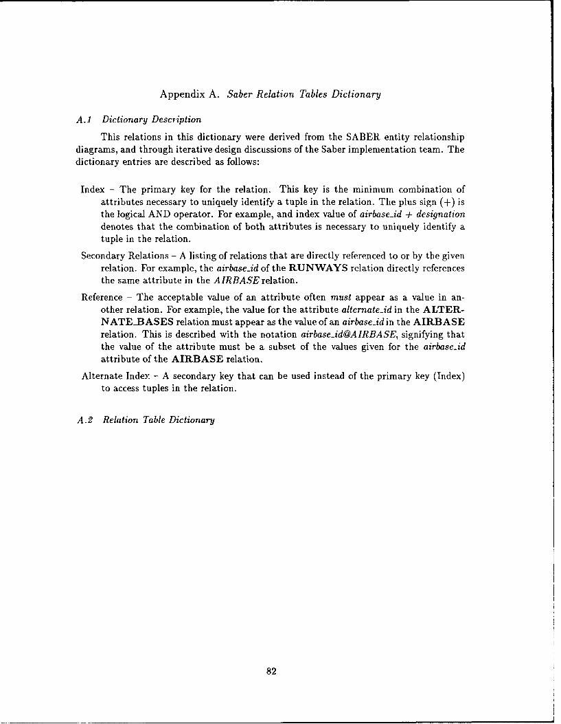
Appendix A. Saber Relation Tables Dictionary
A.1 Dictionary Description
This relations in this dictionary were derived from the SABER entity relationshipdiagrams, and through iterative design discussions of the Saber implementation team. Thedictionary entries are described as follows:
Index - The primary key for the relation. This key is the minimum combination ofattributes necessary to uniquely identify a tuple in the relation. The plus sign (+) isthe logical AND operator. For example, and index value of airbase-id + designationdenotes that the combination of both attributes is necessary to uniquely identify atuple in the relation.
Secondary Relations - A listing of relations that are directly referenced to or by the givenrelation. For example, the airbase.id of the RUNWAYS relation directly referencesthe same attribute in the AIRBASE relation.
Reference - The acceptable value of an attribute often must appear as a value in an-other relation. For example, the value for the attribute alternateid in the ALTER-NATE__BASES relation must appear as the value of an airbaseid in the AIRBASErelation. This is described with the notation airbase-id@AIRBASE, signifying thatthe value of the attribute must be a subset of the values given for the airbase-idattribute of the AIRBASE relation.
Alternate Index. - A secondary key that can be used instead of the primary key (Index)to access tuples in the relation.
A.2 Relation Table Dictionary
82
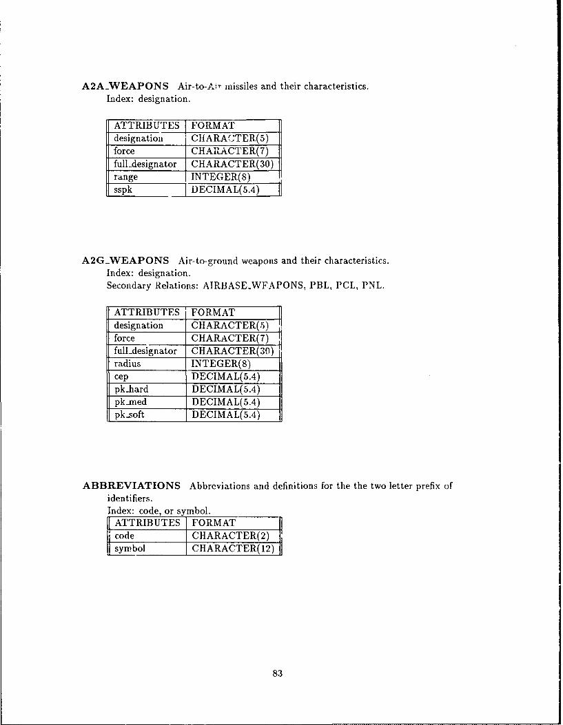
A2A..WEAPONS Air-to-Air inissiles and their characteristics.Index: designation.
ATTRIBUTES FORMATdesignation CHARACTER(5)force CHARAGTER( 7)fuildesignator CHARACTER(30)range INTEGER(8)sspk 7 ] DEGIMAL(5.4)
A2G-WEAPONS Air-to-ground weapons and their characteristics.Index: designation.Secondary Relations: AIRBASE-WFAPONS, PBL, PCL, PNL.
ATTRIBUTES I FORMATdesignation CHARACTER(5)force GHARACTER(7)fuildesignator CHARACTER(30)radius INTEGER(8)cep, DECIMAL(5.4) fpkiiard DECIMAL(5.4)pk-med DECIMAL(5.4)pk-soft DEGIMAL(5.4)
ABBREVIATIONS Abbreviations and definitions for the the two letter prefix ofidentifiers.Index: code, or symbol.
ATTRIBUTES FORMATcode CHARACTER(2)sympbol CHARACTER(12)
83
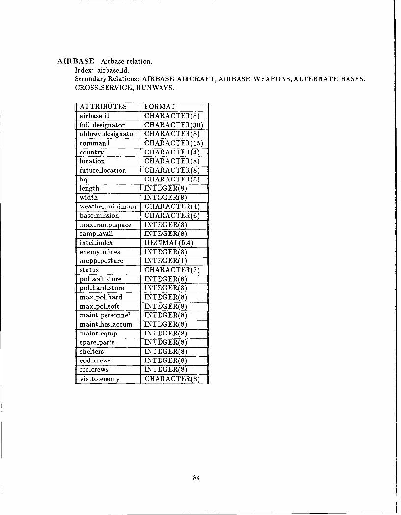
AIRBASE Airbase relation.Index: airbaseid.Secondary Relations: AIRBASE-AIRCRAFT, AIRBASE-WEAPONS, ALTERNATE-BASES,CROSS-.SERVICE, RUNWAYS.
ATTRIBUTES FORMATairbaseid CHARAGTER(8)fuildesignator CHARACTER(30)abbrev -designator CHARAGTER(8)command CHARACTER(15)country CHARACTER(4)
mopp..postre INTEGCER()sttu CHARACTER(7)
-olngttr INTEGER(8)
widtpha INTEGER(8)weather-minimut INTEGER()main pesonne INTEGCER()
-maintrsacu INTEGER(8)
-rmavaeqil INTEGER(8)
enemy-mins INTEGER(8)
psltst INTEGER(8)eodcrewdstr INTEGER(8)
rrrcresi INTEGER(8)
-visto-enemy CHARAGTER(8)
84
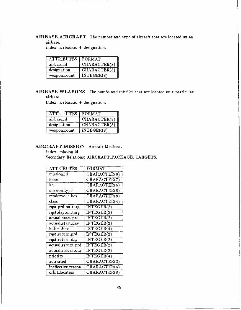
AIRBASE-AIRGRAFT The number and type of aircraft that are located on anai rbase.Index: airbase-id + designation.
ATTRIBUTES FORMATairbase-id CHARACTER(8)designation CHARACTER(5)weapon-count INTEGER(8)
AIRBASE.WEAPONS The bombs and missiles that are located on a particularairbase.Index: airbaseid + designation.
FATTk- 'UTES FORMATairbaseid GHARAGTER(8)designation GHARACTER(5)
weapon-.count INTEGER(8)
AIRCRAFT-MISSION Aircraft Missions.Index: mission-id.Secondary Relations: AIRCRAFT-PACKAG E, TARGETS.
ATTRIBUTES FORMATmission-id CHARACTER(8)force CHARACTER(7)hq CHARACTER(5)missiontype GHARAGTER(8)rendezvous-hlex CHARAGTER(8)class CHARACTER(4)rqst-prd-on-.targ INTEGER(2)rqst-day.on...arg INTEGER(2)actualstart prd INTEGER(2)actual-start day INTEGER(2)loiter-time INTEGER(4)rqst-return-prd INTEGER(2)rqst-return-day INTEGER(2)actualreturn prd INTEGER(2)actual-return -day INTEGER(2)priority INTEGER(4)activated GHARAGTER(3)ineffective-.reason CHARAGTER(4)orbit-location CHARACTER(8)
85
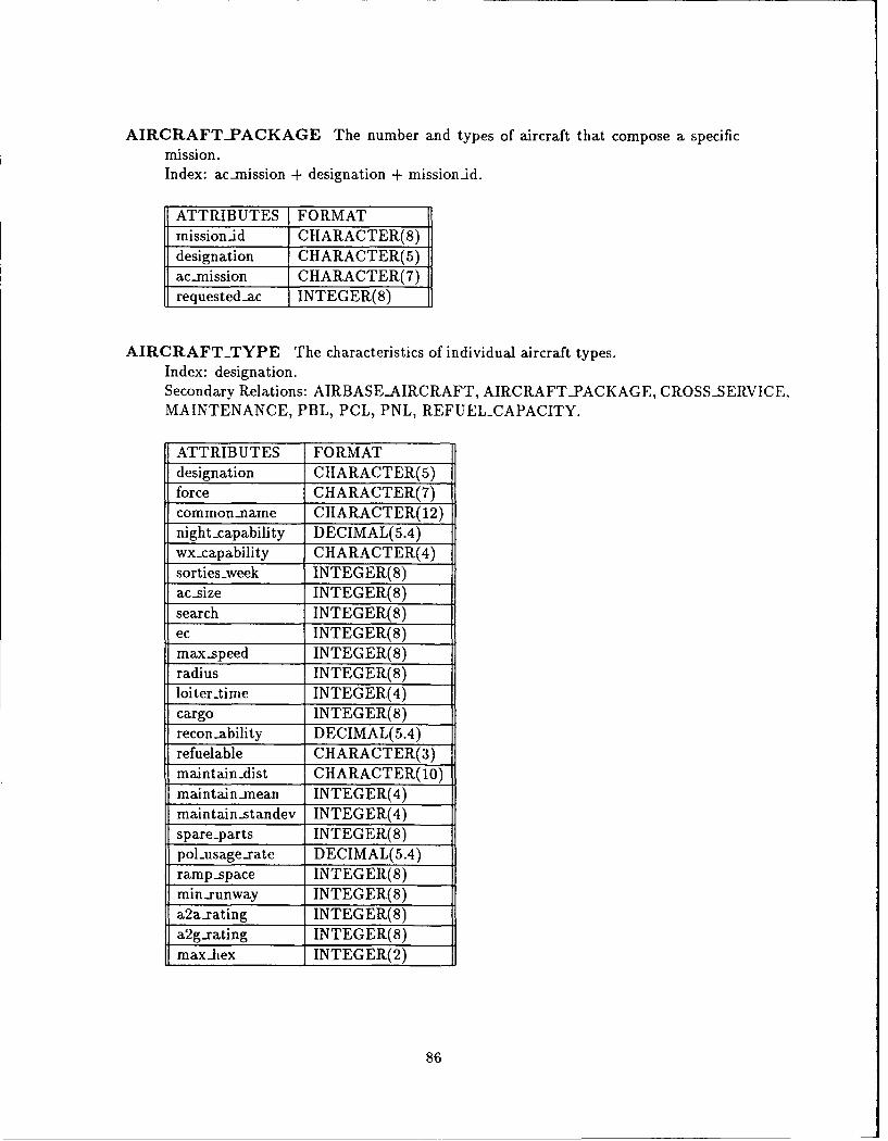
AIRCRAFT-PACKAGE The number and types of aircraft that compose a specificmission.Index: ac-mission + designation + missionid.
ATTRIBUTES FORMATmissionid CHARACTER(8)designation CHARACTER(5)ac-mission CHARACTER(7)requestedac INTEGER(8)
AIRCRAFT-TYPE The characteristics of individual aircraft types.Index: designation.Secondary Relations: AIRBASEAIRCRAFT, AIRCRAFT-PACKAGE, CROSS-SERVICE,MAINTENANCE, PBL, PCL, PNL, REFUEL-CAPACITY.
ATTRIBUTES FORMATdesignation CHARACTER(5)force CHARACTER(7)common-name CHARACTER(12)night-capability DECIMAL(5.4)wx-capability CHARACTER(4)sorties-week INTEGER(8)ac-size INTEGER(8)search INTEGER(8)ec INTEGER(8)max-speed INTEGER(8)radius INTEGER(8)loitertime INTEGER(4)cargo INTEGER(8)recon-ability DECIMAL(5.4)refuelable CHARACTER(3)maintain-dist CHARACTER(10)maintain-mean INTEGER(4)maintain-standev INTEGER(4)spare-parts INTEGER(8)pol-usage-rate DECIMAL(5.4)ramp-space INTEGER(8)min-runway INTEGER(8)a2a-rating INTEGER(8)a2g-rating INTEGER(8)max-hex INTEGER(2)
86
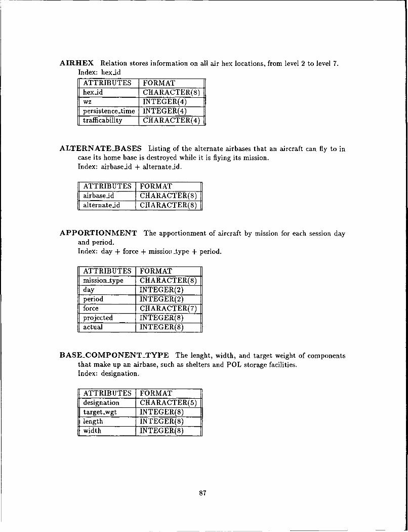
AIRHEX Relation stores information on all air hex locations, from level 2 to level 7.Index: hex-id
ATTRIBUTES FORMAThex-id CHARACTER(8)wz INTEGER(4)persistence-time INTEGER(4)trafficability CHARACTER(4)
ALTERNATE-BASES Listing of the alternate airbases that an aircraft can fly to incase its home base is destroyed while it is flying its mission.Index: airbase-id + alternate-id.
ATTRIBUTES FORMATairbaseid CHARACTER(8)alternateid CHARACTER(8)
APPORTIONMENT The apportionment of aircraft by mission for each session dayand period.Index: day + force + missioitype + period.
ATTRIBUTES FORMATmission-type CHARACTER(8)day INTEGER(2)period INTEGER(2)force CHARACTER(7)projected INTEGER(8)actual INTEGER(S)
BASECOMPONENTTYPE The lenght, width, and target weight of componentsthat make up an airbase, such as shelters and POL storage facilities.Index: designation.
ATTRIBUTES FORMATdesignation CHARACTER(5)target-wgt INTEGER(S)length INTEGER(S)width INTEGER(8)
87
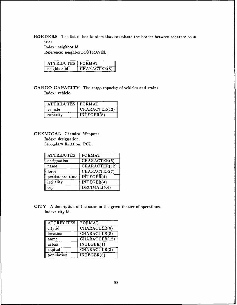
BORDERS The list of hex borders that constitute the border between separate coun-tries.Index: neighbor-idReference: neighbor id@TRAVEL.
ATTRIBUTES FORMATneighbor-id CHARACTER(8)
CARGO-CAPACITY The cargo capacity of vehicles and trains.Index: vehicle.
ATTRIBUTES FORMATvehicle CHARACTER(12)capacity INTEGER(8)
CHEMICAL Chemical Weapons.Index: designation.Secondary Relation: PCL.
ATTRIBUTES FORMATdesignation CHARACTER(5)name CHARACTER(12)force CHARACTER(7)persistence-time INTEGER(4)lethality INTEGER(4)cep DECIMAL(5.4)
CITY A description of the cities in the given theater of operations.Index: cityJd.
ATTRIBUTES FORMATcityid CHARACTER(8)location CHARACTER(8)name CHARACTER(12)urban INTEGER(I)capital CHARACTER(3)population INTEGER(8)
88
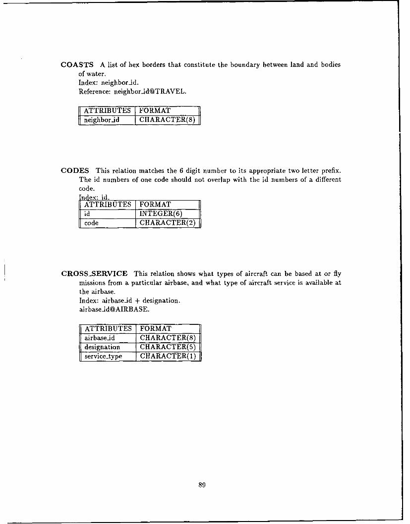
COASTS A list of hex borders that constitute the boundary between land and bodiesof water.Index: neighbor-id.Reference: neighbor-idOTRAVEL.
ATTRIBUTES FORMATneighbor-id CHARACTER(8)]
CODES This relation matches the 6 digit number to its appropriate two letter prefix.The id numbers of one code should not overlap with the id numbers of a differentcode.Index: id.
ATTRIBUTES FORMATid INTEGER(6)code CHARACTER(2)
CROSS-SERVICE This relation shows what types of aircraft can be based at or flymissions from a particular airbase, and what type of aircraft service is available atthe airbase.Index: airbaseid + designation.airbaseid@AIRBASE.
ATTRIBUTES FORMATairbase.id CHARACTER(8)designation CHARACTER(5)service-type CHARACTER(1)
89
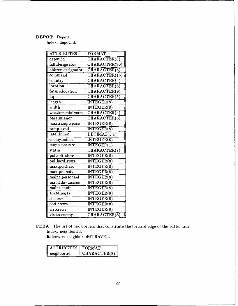
DEPOT Depots.Index: depot-id.
ATTRIBUTES FORMATdepot-id CHARACTER(8)fuildesignator CHARACTER(30)abbrev-Aesignator GHARACTER(8)command CHARAGTER(15)country CHARACTER(4)location GHARAGTER(8)future-location CHARACTER(8)hq GHARACTER(5)length INTEGER(8)width INTEGER(8)weather-minimum CHARAGTER(4)base-mnission CHARACTER(6)max..xamp..space INTEGER(8)ramp-.avail 1NTEGER(8)intel-index DECIMAL(5.4)enemy-inines INTEGER(8)mopp-posture INTEGER( 1)status CHARAGTER(7)pol-soft-store INTEGER(8)pol-hard-store INTEGER(8)max-.polhbard INTEGER(8)mai-pol-soft INTEGER(8)maint-personnel INTEGER(S)maint-hrs-accum INTEGER(8)maint-equip INTEGER(8)spare-parts INTEGER(8)shelters INTEGER(8)eod-xrews INTEGER(8)rrr-.crews INTEGER(8)visAo..enemy CHARACTER(8)
FEBA The list of hex borders that constitute the forward edge of the battle area.Index: neighborid.Reference: neighborid @TRAVEL.
1ATTRIBUTES FORMATneig-hbor..id CHARACTER(8)
90
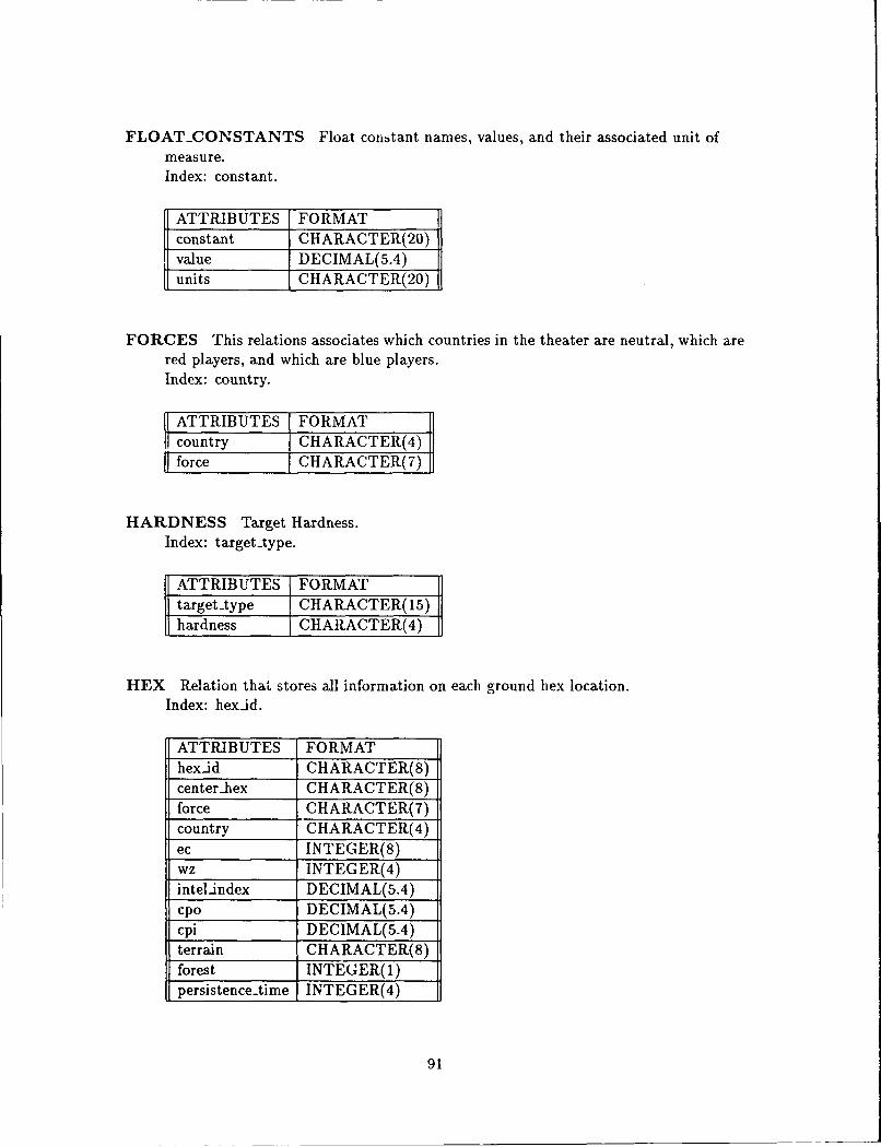
FLOAT-CONSTANTS Float constant names, values, and their associated unit ofmeasure.Index: constant.
ATTRIBUTES FORMATconstant CHARACTER(20)value DECIMAL(5.4)units CHARACTER(20)
FORCES This relations associates which countries in the theater are neutral, which arered players, and which are blue players.Index: country.
ATTRIBUTES FORMATcountry CHARACTER(4)force CHARACTER(7)
HARDNESS Target Hardness.Index: targettype.
ATTRIBUTES FORMATtargettype CHARACTER(15)hardness CHARACTER(4)
HEX Relation that stores all information on each ground hex location.Index: hexid.
ATTRIBUTES FORMAThexid CHARACTER(8)center-hex CHARACTER(8)force CHARACTER(7)country CHARACTER(4)ec INTEGER(8)wz INTEGER(4)intel-index DECIMAL(5.4)cpo DECIMAL(5.4)cpi DECIMAL(5.4)terrain CHARACTER(8)forest INTEGER(l)persistence-time INTEGER(4)
91
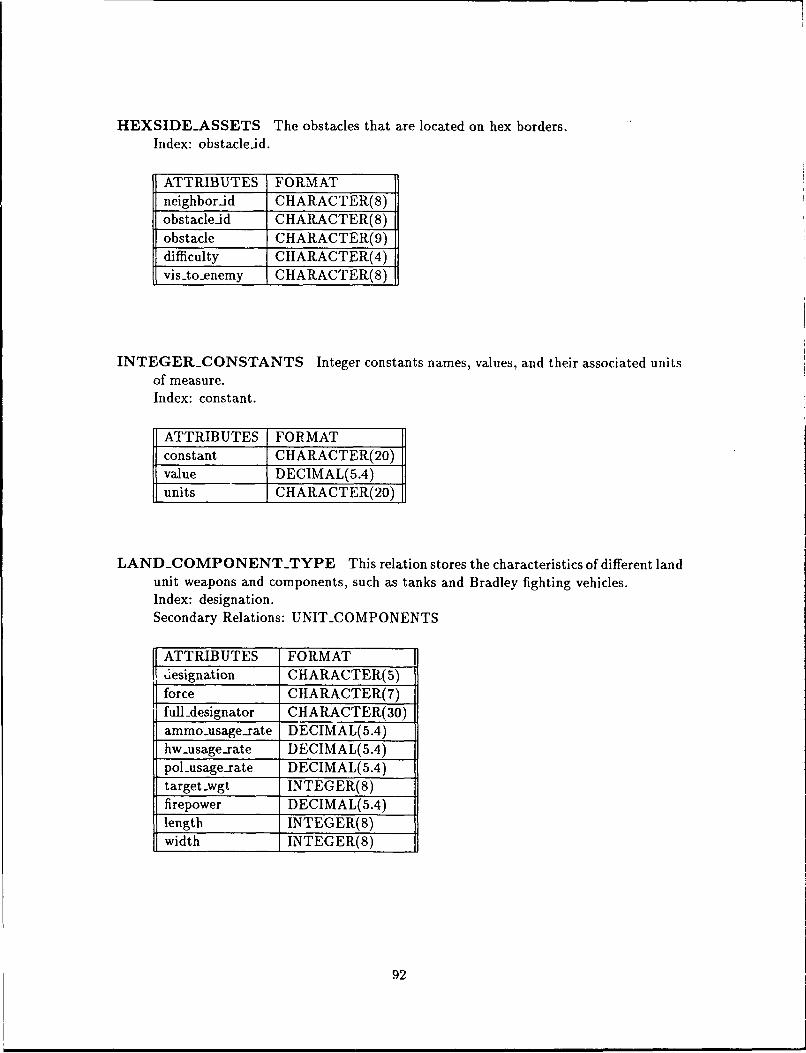
HEXSIDE-ASSETS The obstacles that are located on hex borders.Index: obstacleid.
ATTRIBUTES FORMATneighborid GHARACTER(8)obstacleid CHARAGTER(8)obstacle CHARACTER(9)difficulty GHARACTER(4)visto-enemy GHARACTER(8)
INTEGER-.CONSTANTS Integer constants names, values, and their associated unitsof measure.Index: constant.
ATTRIBUTES FOR MATconstant CHARACTER(20)value DECIMAL(5.4)units CHARACTER(20)
LAND-COMPONENT.TYPE This relation stores the characteristics of different landunit weapons and components, such as tanks and Bradley fighting vehicles.Index: designation.Secondary Relations: UNIT-COMPONENTS
SATTRIBUTES FORMATdesignation CHARACTER(5)
Sforce CHARACTER(7)_full-designator CHARACTER(30)ammo-usagesrate DECIMAL(5.4)hw..usage-rate DECIMAL(5.4)
pol-usage-rate DECIMAL(5.4)target-wgt INTEGER(8)
-firepower DECIMAL(5.4)length INTEGER(S)width INTEGER(8)
92
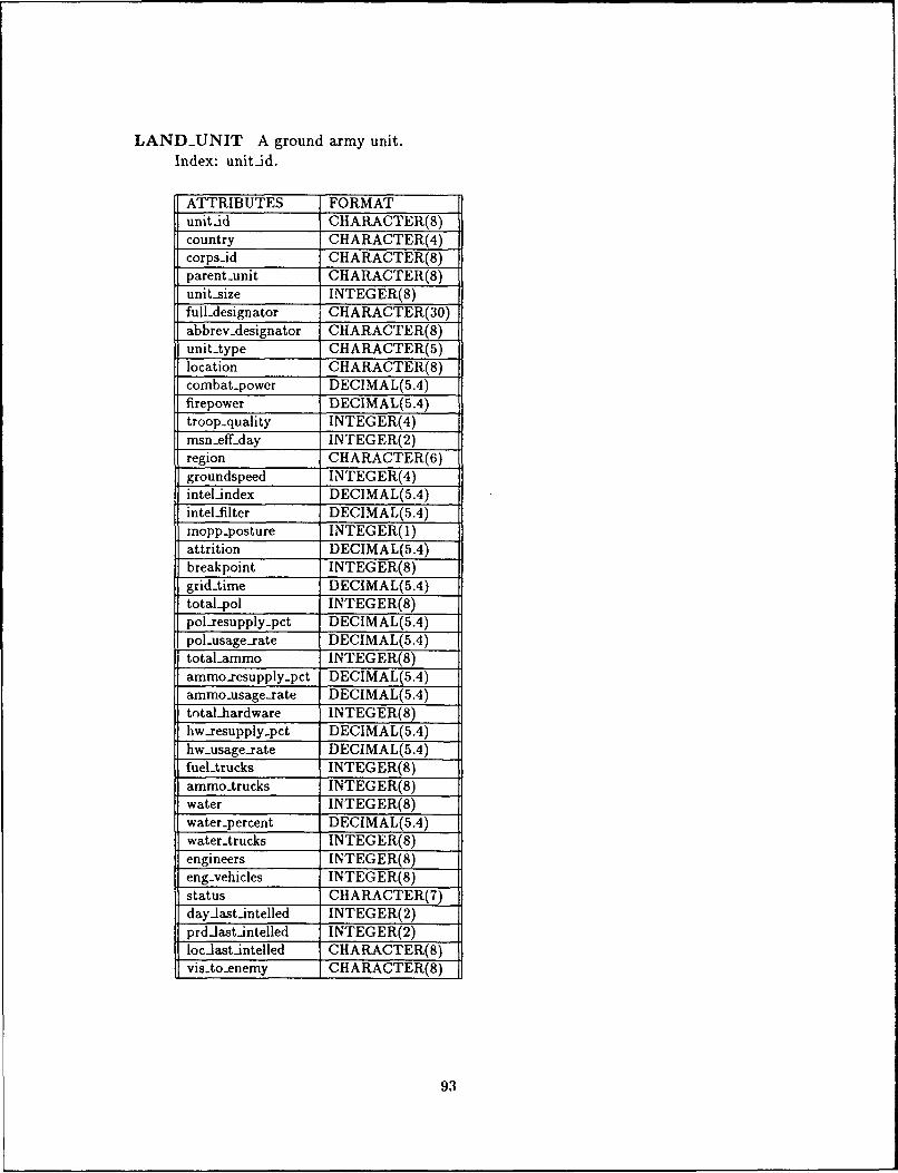
LAND-UNIT A ground army unit.Index: unit-id.
ATTRIBUTES FORMATunit-id CHARACTER(S)country GHARACTER(4)corps-id GHARACTER(8)parent-unit CHARACTER(8)unit-size INTEGER(8)fuildesignator GIIARACTER(30)abbrev-Aesignator CHARACTER(8)unit-type CHARACTER(5)location CHARACTER(8)combat-power DEGIMAL(5.4)firepower DECIMAL(5.4)troop-.quality INTEGER(4)msn-eff-day INTEGER(2)region CHARACTER(6)groundspeed INTEGER(4)intel-index DECIMAL(5.4)intel-filter DEGIMAL(5.4)mopp..posture INTEGER(l)attrition DECIMAL(5.4)breakpoint INTEGER(8)grid.Aimne DECIMAL(5.4)total-pol INTEGER(8)pol-resupply-pct DECIMAL(5.4)pol-usage-.rate DECIMAL(5.4)total-ammo INTEGER(8)ammo-resupply-pct DECIMAL(5.4)amnmo-ilsage-rate DECIMAL(5.4)total-hardware INTEGER(8)hw-resupply..pct DECIMAL(5.4)hw-.usage-rate DECIMAL(5.4)fuel-trucks INTEGER(8)ammo-trucks INTEGER(8)water INTEGER(8)water-percent DECIMAL(5.4)water-trucks INTEGER(8)engineers INTEGER(8)eng-vehicles INTEGER(8)status GHARACTER(7)day-last-intelled INTEGER(2)prd-last-intelled INTEGER(2)loc-last-intelled CHARAGTER(8)vis-to-enemny CHARACTER(8)
93
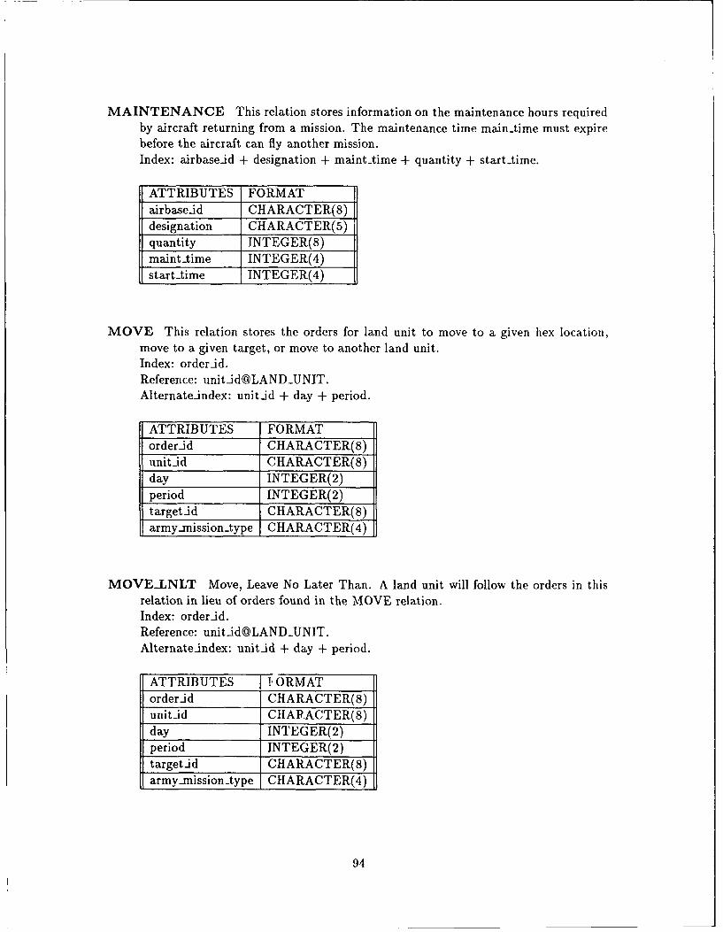
MAINTENANCE This relation stores information on the maintenance hours requiredby aircraft returning from a mission. The maintenance time main-time must expirebefore the aircraft can fly another mission.Index: airbaseid + designation + mainttime + quantity + starttime.
ATTRIBUTES FORMATairbaseid CHARACTER(8)designation CHARACTER(5)quantity INTEGER(8)maint-time INTEGER(4)starttime INTEGER(4)
MOVE This relation stores the orders for land unit to move to a given hex location,move to a given target, or move to another land unit.Index: order-id.Reference: [email protected]: unitid + day + period.
ATTRIBUTES FORMATorder.id CHARACTER(8)unit-id CHARACTER(8)day INTEGER(2)period INTEGER(2)target_id CHARACTER(8)army-mission-type CHARACTER(4)
MOVELNLT Move, Leave No Later Than. A land unit will follow the orders in thisrelation in lieu of orders found in the MOVE relation.Index: orderid.Reference: [email protected]: unit-id + day + period.
ATTRIBUTES IORMATorder-id CHARACTER(8)unit-id CHARACTER(8)day INTEGER(2)period INTEGER(2)target-id CHARACTER(8)army-mission -type CHARACTER(4)
94
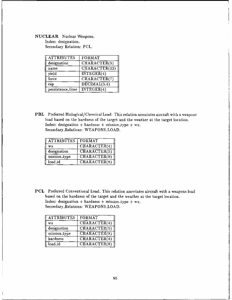
NUCLEAR Nuclear Weapons.Index: designation.Secondary Relation: PCL.
ATTRIBUTES FORMATdesignation CHARACTER(5)name CHARACTER(12)yield INTEGER(4)force CHARACTER(7)cep DECIMAL(5.4)persistence-time INTEGER(4)
PBL Preferred Biological/Chemical Load. This relation associates aircraft with a weaponsload based on the hardness of the target and the weather at the target location.Index: designation + hardness + mission-type + wx.SecondaryRelations: WEAPONS-LOAD.
ATTRIBUTES FORMATwx CHARACTER(4)designation CHARACTER(5)missiontype CHARACTER(8)load-id CHARACTER(8)
PCL Preferred Conventional Load. This relation associates aircraft with a weapons loadbased on the hardness of the target and the weather at the target location.Index: designation + hardness + mission-type + wx.SecondaryRelations: WEAPONS-LOAD.
ATTRIBUTES FORMATwx CHARACTER(4)designation CHARACTER(5)mission-type CHARACTER(8)hardness CHARACTER(4)load-id CHARACTER(8)
95
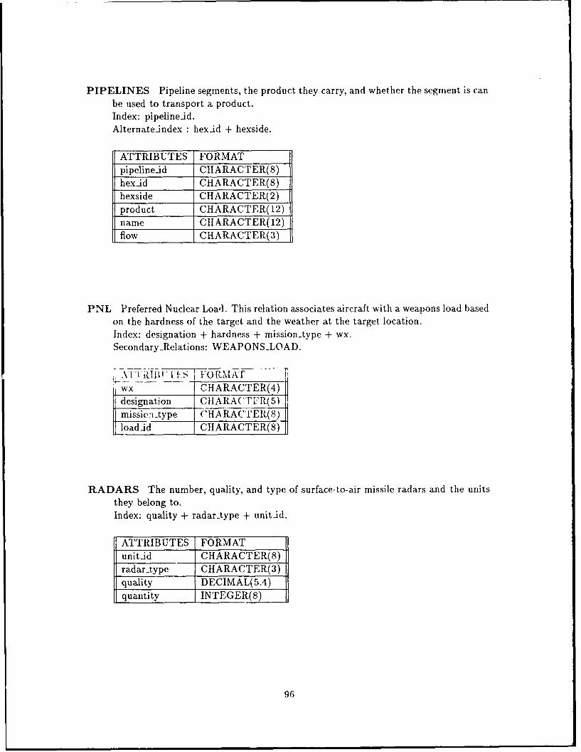
PIPELINES Pipeline segments, the product they carry, and whether the segment is canbe used to transport a product.Index: pipelineid.Alternateindex : hexid + hexside.
ATTRIBUTES FORMATpipelineid CHARACTER(8)hexid CHARACTER(8)hexside CHARACTER(2)product CHARACTER(12)name CH ARACTER(12)flow CHARACTER(3)
PNL Preferred Nuclear Load. This relation associates aircraft with a weapons load basedon the hardness of the target and the weather at the target location.Index: designation + hardness + mission-type + wx.Secondary-Relations: WEAPONS-LOAD.
I, Ai R'I RIII"' - F0 RM ATwx CHARACTER(4)
designation CHARA('T-'R(5)mission -type CHARACTER(8)loadid CHARACTER(8)
RADARS The number, quality, and type of surface-to-air missile radars and the unitsthey belong to.Index: quality + radar-type + unit-id.
ATTRIBUTES FORMATunitid CHARACTER(8)radarAype CHARACTER(3)quality DECIMAL(5.4)quantity INTEGER(8)
96
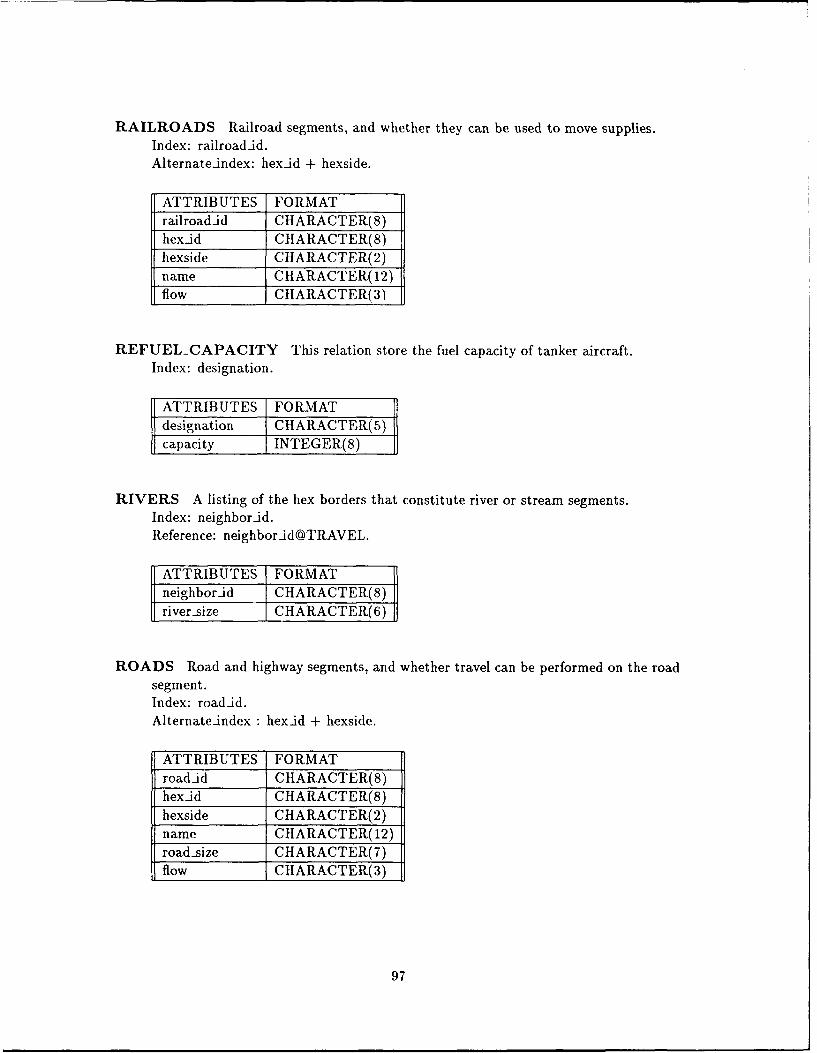
RAILROADS Railroad segments, and whether they can be used to move supplies.Index: railroadid.Alternate-index: hex-id + hexside.
ATTRIBUTES FORMATrailroad-id CHARACTER(8)hexid CIARACTER(8)hexside CHARACTER(2)name CHARACTER(12)flow CHARACTER(3)
REFUEL-CAPACITY This relation store the fuel capacity of tanker aircraft.Index: designation.
ATTRIBUTES FORMATdesignation CHARACTER(5)capacity INTEGER(8)
RIVERS A listing of the hex borders that constitute river or stream segments.Index: neighborid.Reference: neighbor-id@TRAVEL.
ATTRIBUTES FORMATneighbor-id CHARACTER(8)river-size CHARACTER(6)
ROADS Road and highway segments, and whether travel can be performed on the roadsegment.Index: road-id.Alternate-index: hex-id + hexside.
ATTRIBUTES FORMATroad-id CIIARACTER(8)hex-id CHARACTER(8)hexside CHARACTER(2)name CHARACTER(12)road-size CHARACTER(7)flow CHARACTER(3)
97
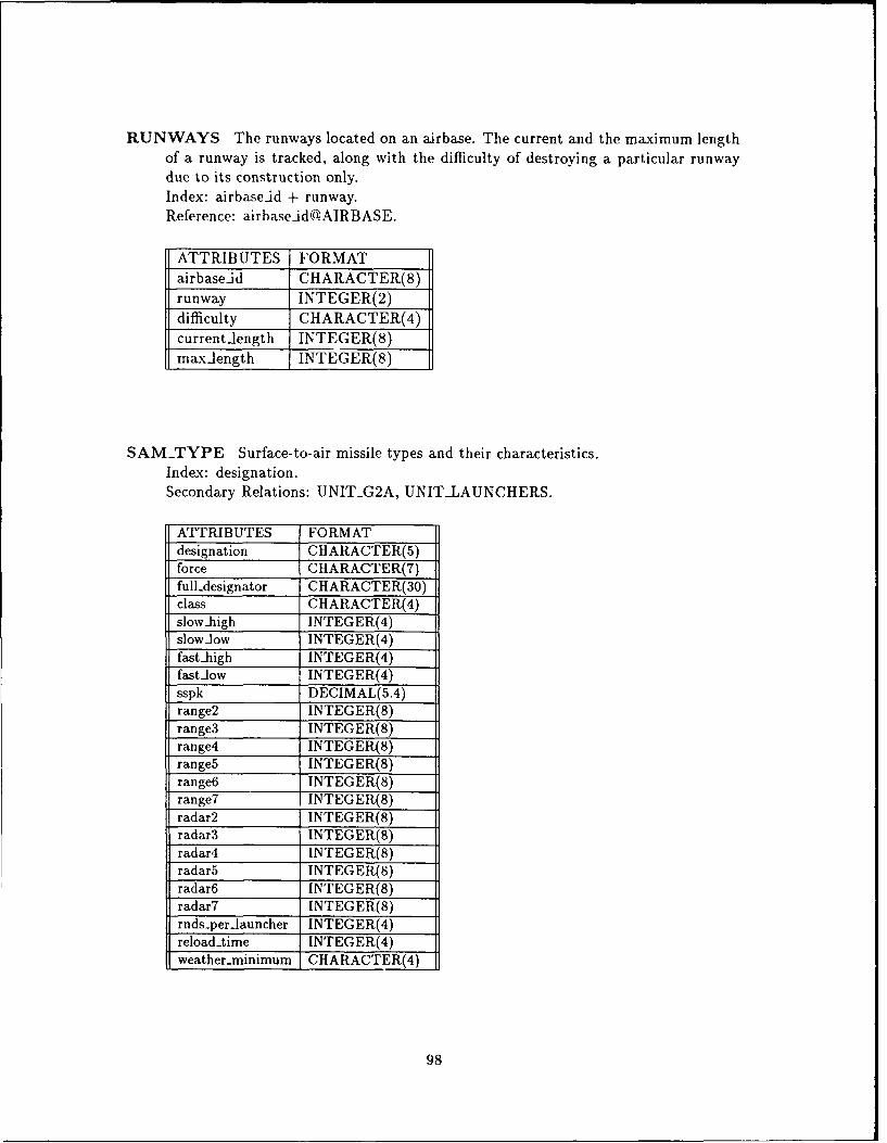
RUNWAYS The runways located on an airbase. The current and the maximum lengthof a runway is tracked, along with the difficulty of destroying a particular runwaydue to its construction only.Index: airbase-id + runway.Reference: airbase-idcaAIRBASE.
ATTRIBUTES FORMATairbase-id CHARACTER(8)
runway INTEGER(2)difficulty CHARACTER(4)current-length INTEGER(8)max-length INTEGER(8)
SAM-.TYPE Surface-to-air missile types and their characteristics.Index: designation.Secondary Relations: UNITG2A, UNIT-LAUNCHERS.
ATTRIBUTES FORMATdesignation CIIARACTER(5)force CHARACTER(7)fuildesignator GHARACTER(30)class CHARACTER(4)slow-high INTEGER(4)slow-low INTEGER(4)fast-high INTEGER(4)fastiow INTEGER(4)
_sspk DECIMAL(5.4)range2 INTEGER(8)range3 INTEGER(8)
-range4 INTEGER(8)-range5 INTEGER(8)-range6 INTEGER(8)-range7 INTEGER(8)radar2 INTEGER(8)radar3 INTEGER(S)radar4 INTEGER(8)
radar5 INTEGER(8)radar6 INTEGER(8)radar7 INTEGER(8)rnds-per-launcber INTEGER(4)reload-time INTEGER(4)weather-.minimum CHARACTER(4)
98
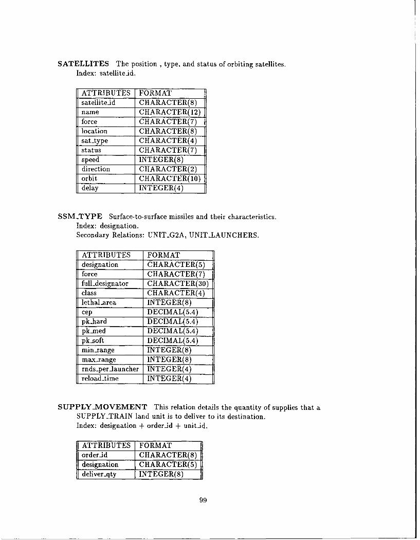
SATELLITES The position , type, and status of orbiting satellites.Index- satellite-id.
ATTRIBUTES FORMATsatellite-id CHARACTER(8)name CHARACTER( 12)force CHARACTER(7)location CIIARACTER(8)sat-type CHARACTER(4)status CHARACTER(7)speed INTEGER(8)direction CHARACTER(2orbit CHARACTER(10)delay INTEGER(4)
S SM-TYPE Surface-to-surface missiles and their characteristics.Index: designation.Secondary Relations: UNITG2A, UNIT-LAUNCHERS.
ATTRIBUTES FORMATdesignation CHARACTER(5)force CHARACTER(7)full-designator CHARACTER(30)'class CHARACTER(4)lethal-area INTEGER(8)cep DECIMAL(5.4)pk-hard DECIMAL(5.4)pk..med DEGIMAL(5.4)pk-soft DECIMAL(5.4)min-range INTEGER(8)max-range INTEGER(8)rnds-perlauncher INTEGER(4)reload-time INTEGER(4)
SUPPLY-.MOVEMENT This relation details the quantity of supplies that aSUPPLY-.TRAIN land unit is to deliver to its destination.Index: designation + order-id + unit-id.
ATTRIBUTES FORMATorderid ICHARACTER(8)designation CIIARACTER(5)deliver..qty INTEGER(8)
99
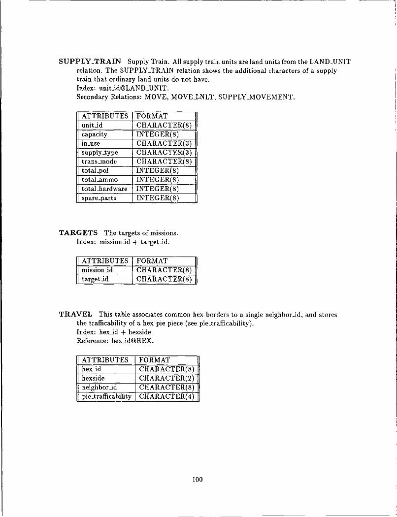
SUPPLY-TRAIN Supply Train. All supply train units are land units from the LAN DUN ITrelation. The SUPPLY-TRAIN relation shows the additional characters of a supplytrain that ordinary land units do not have.Index: [email protected] Relations: MOVE, MOVEILNLT, SUPPLY-MIOVEMENT.
ATTRIBUTES FORMATunit-id CHARACTER(S)capacity INTEGER(8)in-use CHARACTER(3)supply-type CHARACTER(3)trans-.mode CHARACTER(S)total-pol INTEGER(8)totaJ-ammo INTEGER(S)total-hardware INTEGER(S)spare-parts INTEGER(S)
TARGETS The targets of missions.Index: mission-id + target-id.
ATTRIBUTES FORMATmission-id CHARACTER(8)target-d CHARACTER(8)1
TRAVEL This table associates common hex borders to a single neighbor-id, and storesthe trafficability of a hex pie piece (see pie-trafficability).Index: hex-id + hexsideReference: hex-idOHEX.
SATTRIBUTES FORMAThex-id CHARACTER(8)hexside CHARACTER(2) jneighbor-id CHARACTER(8)pie-trafficability CHARACTER(4) j
100
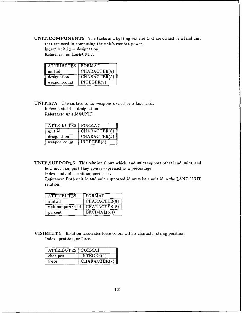
UNIT-COMPONENTS The tanks and fighting vehicles that are owned by a land unitthat are used in computing the unit's combat power.Index: unitid + designation.Reference: unitid@UNIT.
ATTRIBUTES FORMATunitid CHARACTER(8)designation CHARACTER(5)weapon-count INTEGER(S)
UNITS2A The surface-to-air weapons owned by a land unit.Index: unitid + designation.Reference: unitid@UNIT.
ATTRIBUTES FORMATunit-id CHARACTER(S)designation CHARACTER(5)weapon-count INTEGER(S)
UNIT-SUPPORTS This relation shows which land units support other land units, andhow much support they give is expressed as a percentage.Index: unitid + unit-supportedid.Reference: Both unit-id and unit_-supportedid must be a unit-d in the LAND-UNITrelation.
ATTRIBUTES FORMATunitid CHARACTER(8)unit supportedid CHARACTER(8)percent DECIMAL(5.4)
VISIBILITY Relation associates force colors with a character string position.Index: position, or force.
ATTRIBUTES FORMATchar-pos INTEGER(I)force CHARACTER(7)
101

WEAPONS-CLASS The relation tells what relation stores the characteristics of aweapon type.Index: designation.
ATTRIBUTES FORMATdesignation CHARACTER(5)relation CHARACTER(20)
WEAPONS-LOAD This relation associates aircraft types with standard weapon loads.Index: designation + load-id.Reference: PBL, PCL, PNL.
ATTRIBUTES FORMATload-id CHARACTER(8)designation CHARACTER(5)weapon-count INTEGER(8)
WEATHER This relation stores the weather conditions in each zone of the theater forthe duration of the game scenario.Index: day + wx-period + wz.Secondary Relations: AIRHEX, HEX, PBL, PCL, PNL.
ATTRIBUTES FORMATwz INTEGER(4)day INTEGER(2)wx.period INTEGER(2)forecast-good INTEGER(3)forecast-fair INTEGER(3)actual-wx CHARACTER(4)
102
Appendix B. Saber Data Attributes Dictionary
B.1 Dictionary Description
This attributes in this dictionary were derived from the SABER entity relationshipdiagrams, and through iterative design discussions of the Saber implementation team. Thedictionary entries are described as follows:
Where Used - The relation table names that the entry is an attribute in.
Type - The ADA data type of the attribute entry, followed by the length of the data typein parenthesis. For Examples,
e INTEGER(8) - An integer value with 8 digits.
@ CHAR(4) - A character string 4 characters in length.
e FLOAT(5.4) - A real number or floating point value that consists of 5 digitsbefore the decimal point, and 4 digits following the decimal point.
Values - The Range of legal values that an attribute can take on. For descriptive fields,sample values are given as examples.
Alias - An alternative name for an attribute. Relations do not allow multiple attributeswith identical names. Therefore, attributes must be renamed if two similar attributesmust appear in the same relation. For example, the ALTERNATE-BASES rela-tion uses the airbaseid attribute for both the host base and the bases that are thealternate bases. The airbase-id that identifies the alternate bases is renamed withthe alias of alternate-id.
Composition - A description of the components that make up an attribute. For example,the attribute hezid is composed of a two letter identifier 'HX' followed by a 6 digitnumber.
Reference - The acceptable value of an attribute often must appear as a value in an-other relation. For example, the value for the attribute alternate-id in the ALTER-NATE-BASES relation must appear as the value of an airbase-id in the AIRBASErelation. This is described with the notation airbase-id@AIRBASE, signifying thatthe value of the attribute must be a subset of the values given for the airbaseidattribute of the AIRBASE relation.
B.2 Saber Data Attributes
103
a2a._rating The air to air combat (dogfight) rating of an aircraft type.Where Used: AIRCRAFT-TYPE.Type: INTEGER(8).Values: 0-99,999,999.Source: (8:page 164) Ftr Capability Rating
a2g.rating The air to ground attack rating of an aircraft type. The ability of an aircraft toaccurately attack ground targets.Where Used: AIRCRAFT-TYPE.Type: INTEGER(8).Values: 0-99,999,999Source: (8:page 164) Atk Capability Rating
abbrev-designator An 8 character abbreviation of the full-designator field.Where Used: AIRBASE, DEPOT, LAND-UNIT.Type: CHAR(8).Values: Example: 101MID for 101 MECHANIZED INFANTRY DIVISION.
ac-imission The support mission of aircraft within an aircraft mission package.Where Used: AIRCRAFT-PACKAGE.Type: CHAR(7).Values: CAP, EC, ESCORT, PRIMARY, REFUEL, SEAD.
ac-size The size of an aircraft.Where Used: AIRCRAFT-TYPE.Type: INTEGER(8).Values: 0-99,999,999.Source: (15:pp 160-207) Dimension: length * span.
activated Boolean variable that describes whether a requested aircraft mission was activated.Where Used: AIRCRAFT-MISSION.Type: CHAR(3).Values: NO, YES.
actual Actual apportionment of aircraft.Where Used: APPORTIONMENT.Type: INTEGER(8).Values: 0-99,999,999.
actual-return..day The actual session day that an aircraft mission returned to its airbase.Where Used: AIRCRAFT-MISSION.Type: INTEGER(2).Values: 0-num-periods.
104
actual-return.prd The actual period that an aircraft mission returned to its airbase.Where Used: AIRCRAFT-MISSION.Type: INTEGER(2).Values: 0-num-days.
actual-start-day The actual day that an aircraft mission hit its target.Where Used: AIRCRAFT-MISSION.Type: INTEGER(2).Values: 0-num-days.
actual-start.prd The actual period that an aircraft mission hit its target.Where Used: AIRCRAFT-MISSION.Type: INTEGER(2).Values: 0-num-days.
actual-wx The actual weather that is occuring within a weather zone.Where Used: WEATHER.Type: CHAR(4).Values: FAIR, GD, POOR.
airbase-id The unique identifier of an airbase asset.Where Used: AIRBASE, AIRBASEAIRCRAFT, AIRBASEWEAPONS, ALTERNATE-BASES,CROSS-SERVICE, MAINTENANCE, RUNWAYS.Type: CHAR(8).Values: AB00001-AB009999Alias: target-id.Composition: Two letter identifier 'AB' followed by a 6 digit number. Airbases are numberedsequentially.
alternateid The airbase-id of an alternate airbase.Where Used: ALTERNATE-BASES.Type: CHAR(8).Values: Same as airbase-id.Composition: Same as airbase-id.Reference: airbase-id@AIRBASE.
ammo-resupply-pct The percentage of ammunition that get resupplied to a unit.Where Used: LAND-UNIT.Type: FLOAT(5.4)Values: 0.0-100.0000 (percent).
ammo.trucks The number of ammunition trucks owned by a particular land unit.Where Used: LAND-UNIT.Type: INTEGER(8).Values: 0-99,999,999.
105
ammo-usage -rate The amount of ammunition a unit uses on a daily basis.Where Used: LANDCOMPONENTTYPE, LAND-UNIT.Type: FLOAT(5.4)Values: 0.0-99999.9999 (tons/day).(8:pp 82, 87, 464) Rounds on board, Divisional Supply Requirements.
army -mission type The mission of land unit. (attack, defend, move)Where Used: MOVE, MOVELNLT.Type: CHAR(4).Values: ATK, DEF, MOVE, SPT, WTD.
attrition Unit attrition.Where Used: LAND-UNIT.Type: FLOAT(5.4).Values: Computed by simulation.
base-mission The mission of an airbase (Deploy, Not Applicable)Where Used: AIRBASE, DEPOT.Type: CHAR(6).Values: DEPLOY, NA.
breakpoint The minimum combat-power level that a land-unit must sustain in order to engagein battles. When the combat-power of a unit drops below its breakpoint level, the unit au-tomatically begins to retreat.Where Used: LAND-UNIT.Type: INTEGER(8).
capacity The cargo capacity of vehicles and trains, and the tuel capacity of tanker aircraft (tons).Where Used: CARGO-CAPACITY, REFUEL-CAPACITY, SUPPLY-TRAIN.Type: INTEGER(8).Values: 0-99,999,999 (tons).Source: (35) Trucks - Max Load; (8:page 466) Vehicle - Load; (8:page 552) Tanker - InFlight Refueling.
capital Boolean variable that describes whether a city is a capital of a country.Where Used: CITY.Type: CHAR(3)Values: YES, NO.
cargo The cargo capacity of an aircraft.Where Used: AIRCRAFT-TYPE.Type: INTEGER(8).Values: 0-99,999,999 (tons).Source: (15:pp 550-551) Payload.
106
center-hex The air hex located directly over the associated ground hexad.Where Used: HEX.Type: CHAR(8).Values: HX010000-HX079999.Alias: center-hex, location, orbit-location, rendezvous-hex.COMP: Two letter identifier 'HX' followed by 6 digit number. The first two digits are thehex level. The second set of two digits are the X-coordinate index, and the last set of twodigits are the Y-coordinate index.Reference: hex-id@HEX.
cep Circular error of probability.Where Used: A2GWEAPONS, CHEMICAL, NUCLEAR, SSMTYPE.Type: FLOAT(5.4)Values: 0.0-99999.9999 (meters)Source: (8:page 440) CEP
char-pos The position within the character string field visibility.Where Used: VISIBILITY.Type: INTEGER(l).Values: 0-8.
city.id Unique identifier for a city.Where Used: CITY.Type: CHAR(8).Values: CYOO001-CY09999.Composition: Two letter identifier 'CY' followed by a 6 digit number. Cities are numberedsequentially.
class The class of weapon. (Conventional, Chemical/Biological, or Nuclear).Where Used: AIRCRAFT-MISSION, WEAPON-CLASS, SAM-TYPE, SSMTYPE.Type: CHAR(4).Values: CHEM, CONV, NUKE.
code Two letter abbreviation used with identifiers.Where Used: ABBREVIATIONS, CODES.Type: CHAR(2).Values: AB, CY, DP, HX, OB, LU, MS, NB, PI, RD, RR, ST, SU, WL.
combat-power Combat power.Where Used: LAND-UNIT.Type: FLOAT(5.4)
command The air force command that operates an airbase.Where Used: AIRBASE, DEPOT.Type: CHAR(15).Values: Examples: USAFE, MAC, PACAF, SAC, TAG)
107
common.name The Nato common name of a weapon or aircraft.Where Used: AIRCRAFT-TYPE, A2AWEAPONS, A2GWEAPONS, LANDCOMPONENTTYPE,SAM-TYPE, SSMTYPE.Type: CHAR(12).Values: Example: EAGLE, FOXBAT, SCUD.
constant The name of a program constant or database constant.Where Used: FLOAT-CONSTANTS, INTEGER-CONSTANTS.Type: CHAR(20).
corps.d Corps identifier. The identifier of the corps land unit.Where Used: LAND-UNIT.Type: CHAR(8).Values: LU000001-LU999999.Composition: Same as unitid. Two letter ide-ntifier 'LU' followed by a 6 digit number.Reference: unitjd@LANDUNIT. Each corps-id must appear as an unitid in the LAND-UNITrelation.
country The country a ground hex is located in, or the country that owns a particular asset.Where Used: AIRBASE, DEPOT, FORCES, HEX, LAND-UNIT.Type: CHAR(4).Values: NK (North Korea), SK (South Korea), USSR, USA, etc.
cpi Combat Power In. The firepower that is being projected into a particular ground level hex.Where Used: HEX.Type: FLOAT(5.4)Values: Computed from units and weapons.
cpo Combat Power Out. The firepower that is being projected out of a particular ground levelhex.Where Used: HEX.Type: FLOAT(5.4)Values: Computed from units and weapons.
current length The current length of a runway.Where Used: RUNWAYS.Type: INTEGER(8)Values: 0-99,999 (meters).
cycle Attribute records whether a session period occurs during the day or during the night.Where Used: CYCLE.Type: CHAR(5).Values: DAY, NIGHT.
108
day The session day.Where Used: APPORTIONMENT, MOVE, MOVELNLT, STAGING-BASE, WEATHER.
Type: INTEGER(2).Values: 0-99.Alias: rqst-day on-target, actual-start-day, rqst-return-day, actual-return-day.
daydast-intelled The last day intelligence was performed on a unit.Where Used: LAND-UNIT.Type: INTEGER(2).Values: 0-maxdays.
delay The time delay required by a satellite from the time of its launching to the time is opera-tional in orbit. (days)Where Used: SATELLITES.
Type: INTEGER(4).Values: 0-365.
deliver-qty Deliver quantity. The quantity of a weapon that a supply train should deliver to itsdestination unit or airbase.Where Used: SUPPLY-MOVEMENT.Type: INTEGER(8).Values: 0-99,999,999 (tons).
depot.id Unique identifier for a depot.Where Used: DEFOT.
Type: CHAR(8).Values: DP000001-DP009999.Composition: Two letter identifier 'DP' followed by a 6 digit number. Depots are numbered
sequentially.
designation The alphanumeric designation of a weapon type.Where Used: AIRBASEAIRCRAFT, AIRBASEWEAPONS, AIRCRAFT-TYPE, A2AWEAPONS,A2GWEAPONS, CHEMICAL, CROSS-SERVICE, MAINTENANCE, NUCLEAR, PBL,P -, PNL, REFUEL-CAPACITY, SAM-TYPE, SSM-TYPE, SUPPLYMOVEMENT, UNITCOMPONENTS,U NITS2A, UNITS2S, VALIDACMISSIONS.Type: CHAR(5).Values: Example F15A, EF111, SA-6, BMP.
USED (cont.): AIRCRAFT PACKAGE, BASECOMPONENTTYPE, LANDCOMPONENTTYPE,STAGING-BASE, WEAPONS-CLASS, WEAPONS-LOAD.Source: TWX.
difficulty Difficulty level.Where Used: HEXSIDEASSETS, RUNWAYS.
Type: CHAR(4).Values: EXC, VG, GD, FAIR, POOR, VP (Excellent - Very Poor).
109
direction The current direction of travel.Where Used: SATELLITES.Type: CHAR(2).Values: N NE, SE, S, SW, NW (North, Northeast, etc.)
ec Electronic Countermeasure.Where Used: HEX, AIRCRAFT-TYPE.Type: INTEGER(8).Values: 0-99.Source: (8:page 164) EC.
enemy-mines The number of enemy mines that have been dropped on an airbase.Where Used: AIRBASE, DEPOT.Type: INTEGER(8).Values: 0-99,999,999.
eng-vehicles The number of engineer vehicles.Where Used: LAND-UNIT.Type: INTEGER(8).Values: 0-99,999,999.
engineers The number of engineers in a unit.Where Used: LAND-UNIT.Type: INTEGER(8).Values: 0-99,999,999.
eod.crews The number of explosive ordinance crews at an airbase or depot.Where Used: AIRBASE, DEPOT.Type: INTEGER(8).Values: 0-99,999,999.
fast high Air Defense Artillery value for a fast moving attack aircraft with high probability, fromMann p. 138.Where Used: SAM-TYPE.Type: INTEGER(4).Values: 0-9999.Source: (22:page 138).
fastilow Air Defense Artillery value for a fast moving attack aircraft with low probability, fromMann p. 138.Where Used: SAM-TYPE.Type: INTEGER(4).Values: 0-9999.Source: (22:page 138).
110
firepower The firepower of a unit.Where Used: LANDCOMPONENTTYPE, LAND-UNIT.Type: FLOAT(5.4)Values: Computed from the weapons owned by a unit.
flow Boolean variable that describes whether traffic can flow along a railroad, road, or pipelinesegment.Where Used: RAILROADS, ROADS, PIPELINES.Type: CHAR(3).Values: NO, YES.
force The color designation of a player.Where Used: AIRCRAFT-MISSION, APPORTIONMENT, A2AWEAPONS,A2GWEAPONS, FORCES, HEX, NUCLEAR, SAM-TYPE, SATELLITES, STAGING-BASE,SSMTYPE, VISIBILITY.Type: CHAR(7).Values: RED, BLUE, NEUTRAL, etc.
forecast-fair The probability of having fair weather, expressed as a percentage.Where Used: WEATHER.Type: INTEGER(3)Values: 0-100 (percent).
forecast-good The probability of having good weather, expressed as a percentage.Where Used: WEATHER.Type: INTEGER(3).Values: 0-100 (percent).
forest The amount of forestation of a ground hex.Where Used: HEX.Type: INTEGER(l).Values: 0-3.Source : Topography Map.
from-airbaseid The asset-id of the airbase that is the source of inter-airbase aircraft move-ments.Where Used: ACMOVEMENT.Type: CHAR(8).Values: Same as airbase-id.Alias: airbase-id@AIRBASE.
fuel-trucks The amount of fuel trucks in a land unit.Where Used: LAND-UNIT.Type: INTEGER(8).Values: 0-99,999,999.
111
full-designator The full alphanumeric designation of weapon or land unit.Where Used: A2AWEAPONS, A2GWEAPONS, AIRBASE, DEPOT, LAND-COMPONENTTYPE,LANDCOMPONENTTYPE, SAM-TYPE, SSMTYPE, Type: CHAR(30).Values: Example: 101 Mechanized Infantry Division.Source: TWX.
future-location The future location of an airbase.Where Used: AIRBASE, DEPOT.Type: CHAR(8).Values: Same as hexid.Alias: hexid, location.Reference: hex-id@HEX.
grid-time The amount of time needed for a unit to finish crossing a ground hex at a time whena session ended.Where Used: LAND-UNIT.Type: FLOAT(5.4)
groundspeed The top speed that a land unit can move across a land hex.Where Used: LAND-UNIT.Type: INTEGER(4).Values: 0-9999 (km/hr).
hardness The hardness of a target type.Where Used: HARDNESS.Type: CHAR(4).Values: HARD, MED, SOFT.
hex-id Unique hex identifier.Where Used: HEX, AIRHEX, TRAVEL, ROADS, RAILROADS, PIPELINES.Type: CHAR(8).Values: HX010000-HX079999Alias: center-hex, location, orbitjocation, rendezvous-hex.Composition: Two letter identifier 'HX' followed by a 6 digit number. The first two digitsare the hex level, 01 to 07. The second set of two digits are the X-coordinate index, and thelast set of two digits are the Y-coordinate index.Source: Topography map with hex grid overlay.
hexside The identifier which designates the side of a hex.Where Used: PIPELINES, RAILROADS, ROADS, TRAVEL.Type: CHAR(2).Values: N, NE,SE, S, SW, NW (NORTH, NORTHEAST, etc.)
hq The command headquarters of an airbase.Where Used: AIRBASE, AIRCRAFT-MISSION, DEPOT.Type: CHAR(5).Values: Examples: 10.AF, 15-AF.
112
hw resupply-pct Hardware resupply percent.Where Uscd: LAND-UNIT.
Type: FLOAT(5.4)Values: 0.0-100.0000
hwausage..rate The amoupt of hardware used by a unit on a daily basis.Where Used: LAND-COMPONENTTYPE, LAND-UNIT.
Type: FLOAT(5.4)Values: 0-99,999 (Lons/day).Source: (8:page 464) Divisional Daily Supply Requirements.
id Identifier. The 6 digit number used in 8 character identifiers.Where Used: CODES.
Type: INTEGER(6).Values: 1-999999.
in-use Boolean variable that describes whether a supply train is currently in use or not.Where Used: SUPPLY-TRAIN.
Type: CHAR(3).Values: NO, YES.
ineffective-reason The reason an aircraft mission was aborted or ineffective. (Abort, PreventiveMaintenance, Jettisoned Weapons, and Weather).Where Used: AIRCRAFT-MISSION.
Type: CHAR(4).Values: ABRT, PMS, JETT, WX.
intel-filter Intelligence Filter. The amount of intelligence or reconnaissance information thataccurately reaches a unit.Where Used: LAND-UNIT.
Type: FLOAT(5.4).
intel-index Intelligence Index.Where Used: HEX, LAND-UNIT, AIRBASE, DEPOT, SUPPLY-TRAIN.Type: FLOAT(5.4)
launcherqty The quantity of missile launchers for a particular missile.Where Used: UNITS2A, UNITS2S.Type: INTEGER(8).Values: 0-99,999,999.
length The measure of the length of a object.Where Used: AIRBASE, BASE-COMPONENTTYPE, DEPOT, LANDCOMPONENTTYPE,WEIGHT.Type: INTEGER(8).Values: 0-99,999,999 (meters).Source: (3) Length; (35) Length
113
lethal-area The lethal blast radius of a surface-to-surface missile.Where Used: SSMTYPE.Type: INTEGER(8).Values: 0-99,999,999 (meters).Source: (22:page 112) Lethal Area.
lethality The lethality of a chemical weapon.Where Used: CHEMICAL.Type: INTEGER(4).Values: 0-9999.Source: (8:page 416) Harass/Kill and Time to Take Effect value.
load-Ad Weapons load identifier.Where Used: PBL, PCL, PNL, WEAPONS-LOAD.Type: CIlAR(8).Values: WL000001-WL009999.Composition: Two letter identifier 'WL' followed by a 6 digit number. Weapons loads arenumbered sequentially.
loc-last-intelled The hex.id (location) of a land unit at the time it had any reconaissance per-formed on it.Where Used: LAND-UNIT.Type: CHAR(8).Values: HX010000-HX019999.Alias: hex-id.Reference: hex-id@HEX.
location The identifier of the hex that an asset is located in.Where Used: AIRBASE, CITY, DEPOT, LAND-UNIT, SATELLITES, SUPPLY-TRAIN.Type: CHAR(8).Values: HX010101-HX019999.Alias: hexid, center-hex, orbit-location, rendezvous-hex.Two letter identifier 'HX' followed by a 6 digit number. The first two digits are 01 for hexlevel one. The second set of two digits are the X-coordinate index, and the last set of twodigits are the Y-coordinate index.Reference: hex-id.
loiter-time The length of time an aircraft can circle over a battle area, or the requested amountof time that an aircraft package should loiter over its target.Where Used: AIRCRAFT-MISSION, AIRCRAFT-TYPE.Type: INTEGER(4).Values: 0-9999 (hours).
maint-equip Maintenance equipment located on an airbase.Where Used: AIRBASE, DEPOT.Type: INTEGER(8).Values: 0-99,999,999.
114
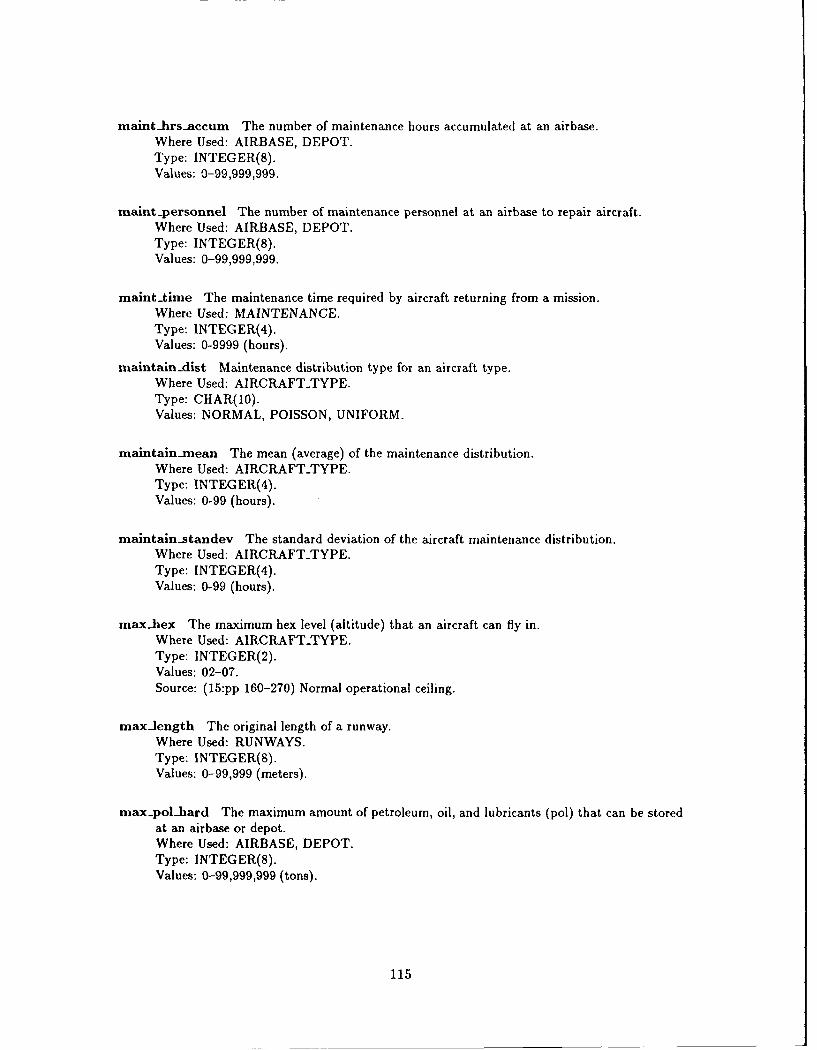
maint-hrsaccum The number of maintenance hours accumulated at an airbase.Where Used: AIRBASE, DEPOT.Type: INTEGER(8).Values: 0-99,999,999.
maint-personnel The number of maintenance personnel at an airbase to repair aircraft.Where Used: AIRBASE, DEPOT.Type: INTEGER(8).Values: 0-99,999,999.
mainttime The maintenance time required by aircraft returning from a mission.Where Used: MAINTENANCE.Type: INTEGER(4).Values: 0-9999 (hours).
maintain-dist Maintenance distribution type for an aircraft type.Where Used: AIRCRAFT-TYPE.Type: CHAR(10).Values: NORMAL, POISSON, UNIFORM.
maintain-mean The mean (average) of the maintenance distribution.Where Used: AIRCRAFT-TYPE.Type: INTEGER(4).Values: 0-99 (hours).
maintain-standev The standard deviation of the aircraft maintenance distribution.Where Used: AIRCRAFT-TYPE.Type: INTEGER(4).Values: 0-99 (hours).
max-hex The maximum hex level (altitude) that an aircraft can fly in.Where Used: AIRCRAFT-TYPE.Type: INTEGER(2).Values: 02-07.Source: (15:pp 160-270) Normal operational ceiling.
maxJength The original length of a runway.Where Used: RUNWAYS.Type: INTEGER(8).Values: 0-99,999 (meters).
max-polhard The maximum amount of petroleum, oil, and lubricants (pol) that can be storedat an airbase or depot.Where Used: AIRBASE, DEPOT.Type: INTEGER(8).Values: 0-99,999,999 (tons).
115
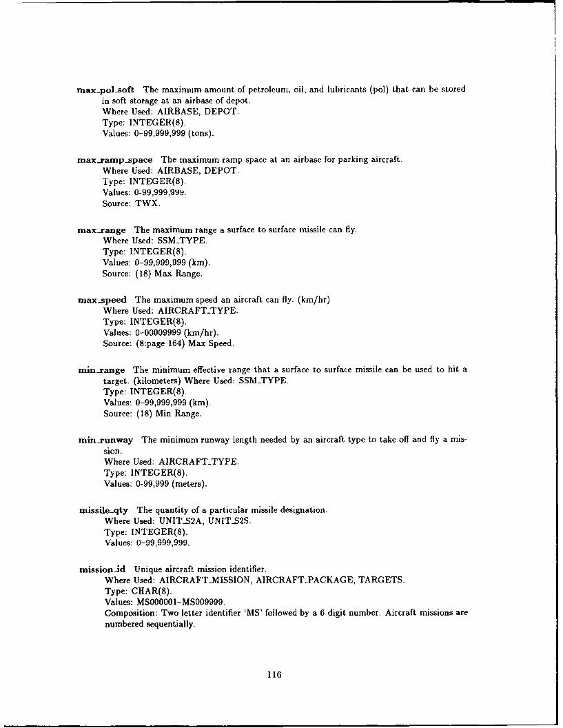
max-pol-soft The maximum amount of petroleum, oil, and lubricants (pol) that can be stored
in soft storage at an airbase of depot.
Where Used: AIRBASE, DEPOT.Type: INTEGER(8).Values: 0-99,999,999 (tons).
max.ramp-space The maximum ramp space at an airbase for parking aircraft.Where Used: AIRBASE, DEPOT.Type: INTEGER(8).Values: 0-99,999,99d.Source: TWX.
max.range The maximum range a surface to surface missile can fly.
Where Used: SSMTYPE.Type: INTEGER(8).Values: 0-99,999,999 (kin).Source: (18) Max Range.
max-speed The maximum speed an aircraft can fly. (km/hr)Where Used: AIRCRAFT-TYPE.
Type: INTEGER(S).Values: 0-00009999 (km/hr).Source: (8:page 164) Max Speed.
rin-range The minimum effective range that a surface to surface missile can be used to hit a
target. (kilometers) Where Used: SSMTYPE.Type: INTEGER(8).Values: 0-99,999,999 (km).Source: (18) Min Range.
minrunway The minimum runway length needed by an aircraft type to take off and fly a mis-
sion.Where Used: AIRCRAFTTYPE.Type: INTEGER(8).Values: 0-99,999 (meters).
missileqty The quantity of a particular missile designation.Where Used: UNITS2A, UNITS2S.
Type: INTEGER(8).Values: 0-99,999,999.
missionid Unique aircraft mission identifier.
Where Used: AIRCRAFT-MISSION, AIRCRAFT-PACKAGE, TARGETS.
Type: CHAR(8).Values: MS000001-MS009999.Composition: Two letter identifier 'MS' followed by a 6 digit number. Aircraft missions are
numbered sequentially.
116
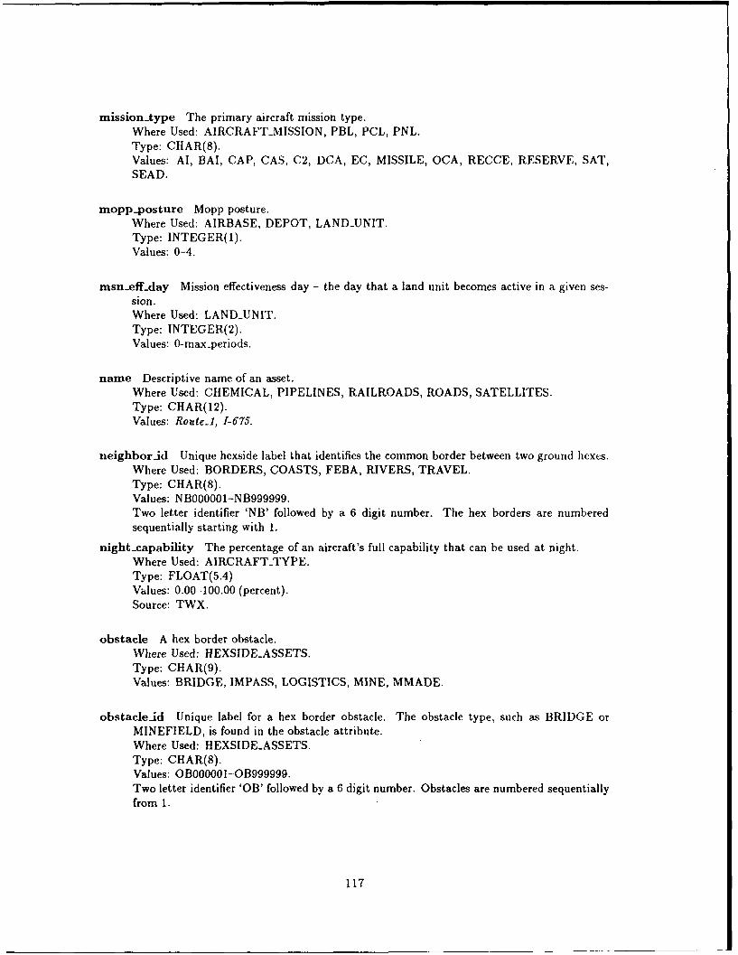
mission~type The primary aircraft mission type.Where Used: AIRCRAFT-MISSION, PBL, PCL, PNL.Type: CHAR(8).Values: Al, BAI, CAP, CAS, C2, DCA, EC, MISSILE, OCA, RECCE, RESERVE, SAT,SEAD.
mopp.posture Mopp posture.Where Used: AIRBASE, DEPOT, LAND-UNIT.Type: INTEGER(1).Values: 0-4.
msn.efftday Mission effectiveness day - the day that a land unit becomes active in a given ses-sion.Where Used: LAND-UNIT.Type: INTEGER(2).Values: 0-max-periods.
name Descriptive name of an asset.Where Used: CHEMICAL, PIPELINES, RAILROADS, ROADS, SATELLITES.Type: CHAR(12).Values: Route-l, 1-675.
neighbor-id Unique hexside label that identifies the common border between two ground hexes.Where Used: BORDERS, COASTS, FEBA, RIVERS, TRAVEL.Type: CHAR(8).Values: NB000001-NB999999.Two letter identifier 'NB' followed by a 6 digit number. The hex borders are numberedsequentially starting with 1.
night-capability The percentage of an aircraft's full capability that can be used at night.Where Used: AIRCRAFT-TYPE.Type: FLOAT(5.4)Values: 0.00-100.00 (percent).Source: TWX.
obstacle A hex border obstacle.Where Used: HEXSIDEASSETS.Type: CHAR(9).Values: BRIDGE, IMPASS, LOGISTICS, MINE, MMADE.
obstacle.id Unique label for a hex border obstacle. The obstacle type, such as BRIDGE orMINEFIELD, is found in the obstacle attribute.Where Used: HEXSIDEASSETS.Type: CHAR(8).Values: 01000001-01999999.Two letter identifier 'OB' followed by a 6 digit number. Obstacles are numbered sequentiallyfrom I.
117
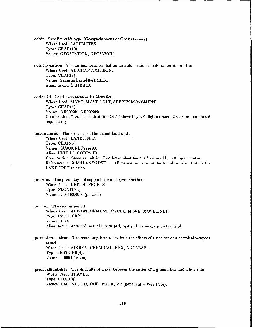
orbit Satellite orbit type (Geosynchronous or Geostationary).Where Used: SATELLITES.Type: CIIAR(10).Values: GEOSTATION, GEOSYNCH.
orbitlocation The air hex location that an aircraft mission should center its orbit in.Where Used: AIRCRAFT-MISSION.Type: CHAR(8).Values: Same as [email protected]: hexad @ AIRHEX.
order-id Land movement order identifier.Where Used: MOVE, MOVELNLT, SUPPLY-MOVEMENT.Type: CHAR(8).Values: OR000001-OR009999.Composition: Two letter identifier 'OR' followed by a 6 digit number. Orders are numberedsequentially.
parent-unit The identifier of the parent land unit.Where Used: LAND-UNIT.Type: CHAR(8).Values: LU00001-LU999999.Alias: UNITJD, CORPSAD.Composition: Same as unitid. Two letter identifier 'LU' followed by a 6 digit number.Reference: unit-id@LANDUNIT. - All parent units must be found as a unitid in theLAND-UNIT relation.
percent The percentage of support one unit gives another.Where Used: UNIT-SUPPORTS.Type: FLOAT(5.4)Values: 0.0-100.0000 (percent)
period The session period.Where Used: APPORTIONMENT, CYCLE, MOVE, MOVELNLT.Type: INTEGER(2).Values: 1-24.Alias: actual-start prd, actual-return-prd, rqst-prd-on-targ, rqst-return-prd.
persistence-time The remaining time a hex feels the effects of a nuclear or a chemical weaponsattack.Where Used: AIRHEX, CHEMICAL, HEX, NUCLEAR.Type: INTEGER(4).Values: 0-9999 (hours).
pie-trafficability The difficulty of travel between the center of a ground hex and a hex side.Where Used: TRAVEL.Type: CHAR(4).Values: EXC, VG, GD, FAIR, POOR, VP (Excellent - Very Poor).
118
pipeline-id Unique identifier for a pipeline segment.Where Used: PIPELINES.Type: CHAR(8).Values: PI000001-P1999999.Composition: Two letter identifier 'PI' followed by a 6 digit number. The pipeline segmentsare numbered sequentially.
pklhard The probability of destroying a hardened target with a direct hit.Where Used: A2GWEAPONS, SSMTYPE.
Type: FLOAT(5.4)Values: 0.0-100.0 (percent).
Source: (22:page 112) PK Hard.
pk._med The probability of destroying a medium-hardened target with a direct hit.Where Used: A2GWEAPONS, SSMTYPE.
Type: FLOAT(5.4)Values: 0.0-100.0 (percent).
Source: (22:page 112) PK Med.
pk.soft The probability of destroying an unhardened target with a direct hit.Where Used: A2GWEAPONS, SSMTYPE.Type: FLOAT(5.4)Values: 0.0-100.0 (percent).
Source: (22:page 112) PK Soft.
pol-lard-store The amount of petroleum, oil, and lubricants in hardened storage.Where Used: AIRBASE, DEPOT.
Type: INTEGER(8).Values: 0-99,999,999 (tons).
pol-resupply-pct Petroleum, oil, and resupply percentage.Where Used. LAND-UNIT.Type: FLOAT(5.4)Values: 0.0 -100.0 (percent).
pol-soft-store The amount of petroleum, oil, and lubricants in soft storage.Where Used: AIRBASE, DEPOT.Type: INTEGER(8).Values: 0-99,999,999 (tons).
pol-usage-rate The amount of tota-pol (petroleum, oil, and lubricants) that a unit used duringa day.Where Used: AIRCRAFT-TYPE, LANDCOMPONENTTYPE, LAND-UNIT.Type: FLOAT(5.4)Values: 0.0-99999.9999 (tons/day)
119
population The population of a city.Where Used: CITY.
Type: INTEGER(8).Values: 0-99,999,999.
prd-last intelled The last session period that intelligence was performed on a unit.Where Used: LAND-UNIT.Type: INTEGER(2).Values: 0-max-periods.
priority Aircraft mission priority.Where Used: AIRCRAFT-MISSION.
Type: INTEGER(4).Values: 0-9999.
product The product carried by a pipeline.Where Used: PIPELINF9.
Type: CHAR(12)Values: OIL, W',.'V L, etc.
projected Prcjected apportionment of aircraft.Where Used: APPORTIONMENT.
Typ-i: INTEGER(8).Values: 0-99,999,999.
quality The quality of a radar system.Where Used: RADARS.
Type: FLOAT(5.4)Values: 0-2.0
quantity Quantity.Where Used: ACMOVEMENT, MAINTENANCE, RADARS, STAGING-BASE.Type: INTEGER(8).Values: 0-99,999,999.
radar2 The ability of a surface-to-air missile radar system to acquire and track targets flying inair hex level 2.Where Used: SAM-TYPE.Type: INTEGER(8).Values: 0-99,999,999.
radar3 The ability of a surface-to-air missile radar system to acquire and track targets flying inair hex level 3.Where Used: SAM-TYPE.Type: INTEGER(8).Values: 0-99,999,999.
120
radar4 The ability of a surface-to-air missile radar system to acquire and track targets flying inair hex level 4.Where Used: SAM-TYPE.Type: INTEGER(8).Values: 0-99,999,999.
radar5 The ability of a surface-to-air missile radar system to acquire and track targets flying inair hex level 5.Where Used: SAM-TYPE.Type: INTEGER(8).Values: 0-99,999,999.
radar6 The ability of a surface-to-air missile radar system to acquire and track targets flying inair hex level 6.Where Used: SAM-TYPE.Type: INTEGER(8).Values: 0-99,999,999.
radar7 The ability of a surface-to-air missile radar system to acquire and track targets flying inair hex level 7.Where Used: SAM-TYPE.Type: INTEGER(8).Values: 0-99,999,999.
radartype The type of radar used with surface to air missile systems. (Acquisition or RadarFire Control).Where Used: RADARS.Type: CHAR(3).Values: ACQ, RFC.
radius The maximum distance an aircraft can fly unrefueled in AIRCRAFT-TYPE, and the ex-plosive radius of an air-to-ground weapon on A2G-WEAPONS.Where Used: AIRCRAFT-TYPE, A2G.WEAPONS.Type: INTEGER(8).Values: 0-99,999Source: (15:pp 160-270) Normal unrefuel range - Aircraft Type.
railroad-id Unique identifier of a railroad seqment.Where Used: RAILROADS.Type: CHAR(8).Values: RR000001-RR999999.Composition: Two letter identifier 'RR' followed by a 6 digit number. The railroad segmentsare numbered sequentially.
121
ramp-avail The amount of ramp space currently available at an airbase.Where Used: AIRBASE, DEPOT.Type: INTEGER(8).Values: 0-99,999,999.Source: TWX.
ramp-space The amount of ramp space taken up by an aircraft type.Where Used: AIRCRAFT-TYPE.Type: INTEGER(8).Values: 0-9999Source: TWX.
range The range of an air-to-air missile.Where Used: A2AWEAPONS.Type: INTEGER(8).Values: 0-99,999,999 (km).Source: (8:page 174) Range.
range2 The range of a surface-to-air missile that is fired at a target flying in air hex level 2.Where Used: SAM-TYPE.Type: INTEGER(8).Values: 0-99,999,999 (km).Source: (8:page 174) Range value adjusted using trigonometry.
range3 The range of a surface-to-air missile that is fired at a target flying in air hex level 3.Where Used: SAM.TYPE.Type: INTEGER(8).Values: 0-99,999,999 (km).Source: (8:page 174) Range value adjusted using trigonometry.
range4 The range of a surface-to-air missile that is fired at a target flying in air hex level 4.Where Used: SAM-TYPE.Type: INTEGER(S).Values: 0-99,999,999 (km).Source: (8:page 174) Range value adjusted using trigonometry.
range5 The range of a surface-to-air missile that is fired at a target flying in air hex level 5.Where Used: SAM-TYPE.Type: INTEGER(8).Values: 0-99,999,999 (km).Source: (8:page 174) Range value adjusted using trigonometry.
range6 The range of a surface-to-air missile that is fired at a target flying in air hex level 6.Where Used: SAM.TYPE.Type: INTEGER(8).Values: 0-99,999,999 (km).Source: (8:page 174) Range value adjusted using trigonometry.
122
range7 The range of a surface-to-air missile that is fired at a target flying in air hex level 7.Where Used: SAMTYPE.Type: INTEGER(8).Values: 0-99,999,999 (km).Source: (8:page 174) Range value adjusted using trigonometry.
reconability The reconaissance ability of an aircraft.Where Used: AIRCRAFT-TYPE.Type: FLOAT(5.4)Values: 0-100.00
refuelable Boolean variable which indicates whether an aircraft type can be refueled in flight.Where Used: AIRCRAFT-TYPE.Type: CHAR(3).Values: NO, YES.
region The region of a hex that a land unit is located in.Where Used: LAND-UNIT.Type: CHAR(6).Values: CENTER, BORDER.
relation The relation table name that contains the type information for a particular weapon.Where Used: WEAPONS-CLASS.Type: CHAR(20).Values: A2AWEAPONS, A2GWEAPONS, CHEMICAL, NUCLEAR, SAM-TYPE, SSMTYPE,COMPONENTTYPE.
reload-time The minimum time necessary to reload a missile launcher after a missile has beenfired.Where Used: SAM-TYPE, SSMTYPE.Type: INTEGER(4).Values: 0-9999.
rendezvous-hex The air hex that the aircraft flying a combined mission come together at.Where Used: AIRCRAFT.MISSION.Type: CHAR(8).
Values: Example: HX030452.Alias: [email protected]: Same as hexid@AIRHEX.
Reference: hex-id@AIRHEX.
requested-ac The quantity of an aircraft type that the user has requested to fly in an aircraftmission.Where Used: AIRCRAFT-PACKAGE.Type: INTEGER(8).Values: 0-99,999,999.
123
river-size The width of a river segment.Where Used: RIVERS.Type: CHAR(6).Values: RIVER, STREAM.
rnds-perlauncher Missile rounds per launcher. The number of missile rounds that are normallyloaded on a single launching platform.Where Used: SAM-TYPE, SSM-TYPE.Type: INTEGER(4).Values: 0-9999.Source: (8:page 190) Missiles Barrels.
roadid Unique identifier of road segment.Where Used: ROADS.Type: CHAR(8). Values: RD000001-RD999999.Composition: Two letter identifier 'RD' followed by a 6 digit number. The road segmentsare numbered sequentially.
road-size The width of a road-segment.Where Used: ROADS.Type: CHAR(7).Values: HIGHWAY, ROAD.
rqst-day-ontarg The requested day that an aircraft mission should hit its target.Where Used: AIRCRAFT-MISSION.Type: INTEGER(2).Values: 0-num-days.
rqst-prd-ontarg The requested period that an aircraft mission should hit its target.Where Used: AIRCRAFT-MISSION.Type: INTEGER(2).Values: 0-num-periods.
rqst-return-day The requested day that an aircraft mission should return to its airbase.Where Used: AIRCRAFT-MISSION.Type: INTEGER(2).Values: 0-num-days.
rqst-return-prd The requested period that an aircraft mission should return to its airbase.Where Used: AIRCRAFT-MISSION.Type: INTEGER(2).Values: 0-num-periods.
rrr-crews The number of rapid runway repair crews available at an airbase.Where Used: AIRBASE, DEPOT.Type: INTEGER(8).Values: 0-99,999,999.
124
runway The runway identifier at an airbase.Where Used: RUNWAYS.Type: INTEGER(2).Values: 0-99.
sat-type Satellite type.Where Used: SATELLITES.Type: CHAR(4).Values: ASAT, NAV.
satellite-id Unique identifier for a satellite. Every satellite is individually tracked.Where Used: SATELLITES.Type: CHAR(8).Values: ST000001-ST009999.Composition: Two letter identifier 'ST' followed by a 6 digit number. Satellites are numberedsequentially.
search The diameter of the sensor's detection area in kilometers.Where Used: AIRCRAFT-TYPE.Type: INTEGER(8).Values: 0-99,999,999 (km).Source: (22:page 110) Search.
service-type The types of aircraft services supported at an airbase.Where Used: CROSS-SERVICE.Type: CHAR(l).Values: B, C, N.Source: TWX.
shelters The number of shelters at an airbase or depot.Where Used: AIRBASE, DEPOT.Type: INTEGER(8).Values: 0-99,999,999.
slow-high Air Defense Artillery value for a slow moving attack aircraft with high probability,from Mann p. 138.Where Used: SAM-TYPE.Type: INTEGER(4).Values: 0-9999. Source: (22:page 137).
slowlow Air Defense Artillery value for a slow moving attack aircraft with low probability, fromMann p. 138.Where Used: SAM.TYPE.Type: INTEGER(4).Values: 0-9999. Source: (22:page 137).
125
sorties-week Maximum aircraft sorties that can be flown by an aircraft per week.Where Used: AIRCRAFT-TYPE.Type: INTEGER(8).Values: 0-99,999,999 (sorties/week).Source: TWX; (8:page 164) Srt Capability Ratings.
spare-parts The amount of spare airplane parts at an airbase, or the number of spare partsrequired by an aircraft type.Where Used: AIRBASE, AIRCRAFTTYPE, DEPOT, SUPPLY-TRAIN.Type: INTEGER(8).Values: 0-99,999,999 (tons).Source: TWX.
speed The speed of a satellite.Where Used: SATELLITES.Type: INTEGER(8).Values: 0-99,999,999 (km/hr).
sspk Single shot probability of a kill.Where Used: A2AWEAPONS, SAM-TYPE.Type: FLOAT(5.4)Values: 0.0-100.0 (percent).Source: (8:page 190) Effectiveness; (22:page 112) PK Air.
starttime The maintenance start time for aircraft that have returned from a mission.Where Used: MAINTENANCE.Type: INTEGER(4).Values: 0-9999.
status The status of asset.Where Used: AIRBASE, DEPOT, LAND-UNIT, SATELLITE.Type: CHAR(7).Values: ACTIVE, GROUND, INACTIVE, OVERRUN.
supplytype Supply train type. Predirect supply trains (PST) can be used multiple times,whereas the assets of a regular supply train (ST) become part of the unit that is being sup-plied. ST type trains get absorbed (disappear) into the unit they are supplying.Where Used: SUPPLY-TRAIN.Type: CHAR(3).Values: PST, ST.
symbol The full length description of the two letter character code used with identifiers.Where Used: ABBREVIATIONS.Type: CHAR(12).Values: AIRBASE, CITY, DEPOT, HEX, OBSTACLE, LAND.UNIT, MISSION, NEIGH-BOR, PIPELINE, ROAD, RAILROAD, SATELLITE, SEAUNIT, WEAPONS-LOAD.
126
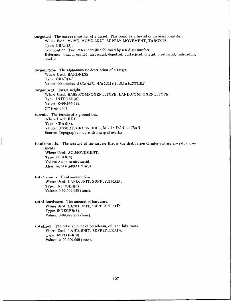
target-id The unique identifier of a target. This could be a hex-id or an asset identifier.Where Used: MOVE, MOVELNLT, SUPPLY-MOVEMENT, TARGETS.Type: CHAR(8).Composition: Two letter identifier followed by a 6 digit number.Reference: hexad, unit.id, airbase.id, depot-id, obstacle-id, city-id, pipeline-id, railroad-id,roadid.
targettype The alphanumeric description of a target.Where Used: HARDNESS.Type: CHAR(15).Values: Examples: AIRBASE, AIRCRAFT, HARD-STORE
target-wgt Target weight.Where Used: BASECOMPONENTTYPE, LANDCOMPONENTTYPE.Type: INTEGER(8).Values: 0-99,999,999.(22:page 158)
terrain The terrain of a ground hex.Where Used: HEX.Type: CHAR(8).Values: DESERT, GREEN, HILL, MOUNTAIN, OCEAN.Source: Topography map with hex grid overlay.
to-airbaseid The asset-id of the airbase that is the destination of inter-airbase aircraft move-ments.Where Used: AC.MOVEMENT.Type: CHAR(8).Values: Same as airbaseid.Alias: airbaseid@AIRBASE.
total-amnmo Total ammunition.Where Used: LAND-UNIT, SUPPLY-TRAIN.Type: INTEGER(8).Values: 0-99,999,999 (tons).
total-hardware The amount of hardware.Where Used: LAND-UNIT, SUPPLY-TRAIN.Type: INTEGER(8).Values: 0-99,999,999 (tons).
total-pol The total amount of petroleum, oil, and lubricants.Where Used: LAND-UNIT, SUPPLY-TRAIN.Type: INTEGER(8).Values: 0-99,999,999 (tons).
127
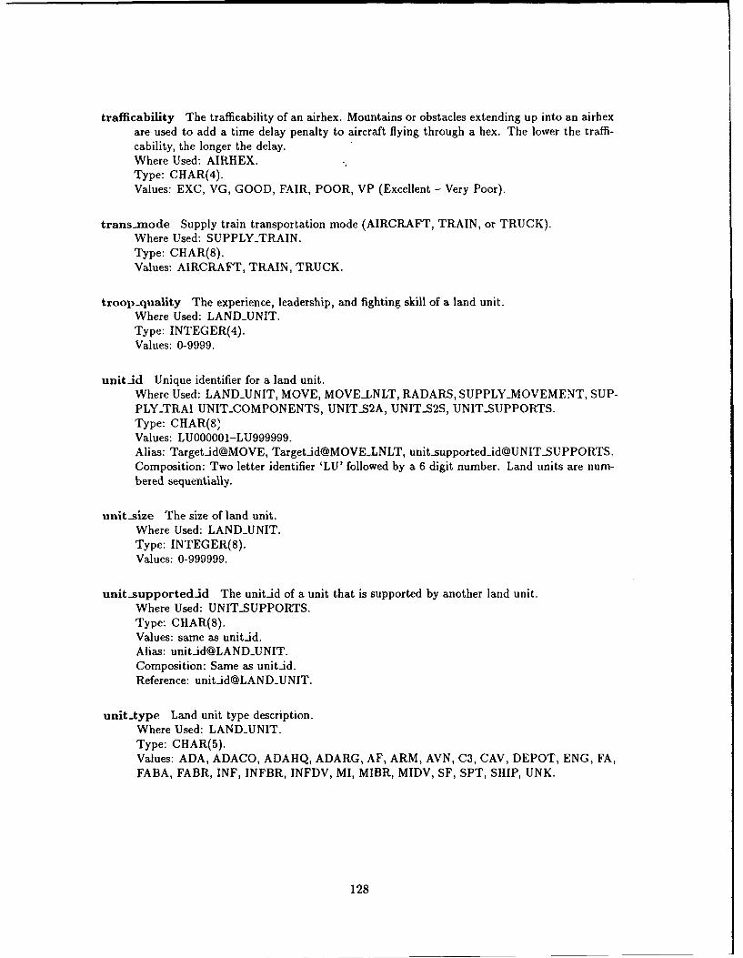
traflicability The trafficability of an airhex. Mountains or obstacles extending up into an airhexare used to add a time delay penalty to aircraft flying through a hex. The lower the traffi-cability, the longer the delay.Where Used: AIRHEX.Type: CHAR(4).Values: EXC, VG, GOOD, FAIR, POOR, VP (Excellent - Very Poor).
trans.node Supply train transportation mode (AIRCRAFT, TRAIN, or TRUCK).Where Used: SUPPLY-TRAIN.Type: CHAR(8).Values: AIRCRAFT, TRAIN, TRUCK.
troop-quality The experience, leadership, and fighting skill of a land unit.Where Used: LAND-UNIT.Type: INTEGER(4).Values: 0-9999.
unit-id Unique identifier for a land unit.Where Used: LAND-UNIT, MOVE, MOVELNLT, RADARS, SUPPLY-MOVEMENT, SUP-PLYTRAI UNIT-COMPONENTS, UNITS2A, UNITS2S, UNIT-SUPPORTS.Type: CHAR(8)Values: LU000001-LU999999.Alias: Target-id@MOVE, Target-id@MOVELNLT, [email protected]: Two letter identifier 'LU' followed by a 6 digit number. Land units are num-bered sequentially.
unit-size The size of land unit.Where Used: LAND-UNIT.Type: INTEGER(8).Values: 0-999999.
unit supported-id The unitid of a unit that is supported by another land unit.Where Used: UNIT-SUPPORTS.Type: CHAR(8).Values: same as unit-id.Alias: [email protected]: Same as unit-id.Reference: unitid@LANDUNIT.
unittype Land unit type description.Where Used: LAND-UNIT.Type: CHAR(5).Values: ADA, ADACO, ADAHQ, ADARG, AF, ARM, AVN, C3, CAV, DEPOT, ENG, FA,FABA, FABR, INF, INFBR, INFDV, MI, MIBR, MIDV, SF, SPT, SHIP, UNK.
128
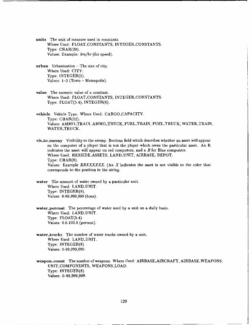
units The unit of measure used in constants.Where Used: FLOAT-CONSTANTS, INTEGER-CONSTANTS.Type: CHAR(20).Values: Example: km/hr (for speed).
urban Urbanization - The size of city.Where Used: CITY.Type: INTEGER(1).Values: 1-3 (Town - Metropolis).
value The numeric value of a constant.Where Used: FLOAT-CONSTANTS, INTEGER-CONSTANTS.Type: FLOAT(5.4), INTEGER(8).
vehicle Vehicle Type. Where Used: CARGO-CAPACITY.Type: CHAR(12).Values: AMMOTRAIN, AMMOTRUCK, FUEL-TRAIN, FUEL-TRUCK, WATER-TRAIN,WATER-TRUCK.
vis-to.enerny Visibility to the enemy. Boolean field which describes whether an asset will appearon the computer of a player that is not the player which owns the particular asset. An Rindicates the asset will appear on red computers, and a B for Blue computers.Where Used: HEXSIDEASSETS, LAND-UNIT, AIRBASE, DEPOT.Type: CHAR(8).Values: Example RBXXXXXX. (An X indicates the asset is not visible to the color thatcorresponds to the position in the string.
water The amount of water owned by a particular unit.Where Used: LAND-UNIT.Type: INTEGER(8).Values: 0-99,999,999 (tons).
water-percent The percentage of water used by a unit on a daily basis.Where Used: LAND-UNIT.Type: FLOAT(5.4)Values: 0.0-100.0 (percent).
waterArucks The number of water trucks owned by a unit.Where Used: LAND-UNIT.Type: INTEGER(8).Values: 0-99,999,999.
weapon-count The number of weapons. Where Used: AIRBASEAIRCRAFT, AIRBASEWEAPONS,UNIT-COMPONENTS, WEAPONS-LOAD.Type: INTEGER(8).Values: 0-99,999,999.
129
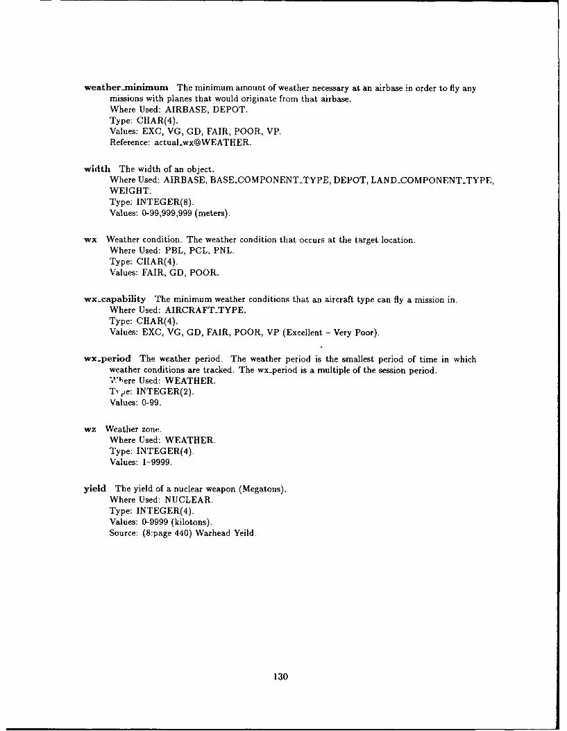
weather.minimum The minimum amount of weather necessary at an airbase in order to fly anymissions with planes that would originate from that airbase.Where Used: AIRBASE, DEPOT.Type: CHAR(4).Values: EXC, VG, GD, FAIR, POOR, VP.Reference: actual-wx@WEATHER.
width The width of an object.Where Used: AIRBASE, BASECOMPONENT.TYPE, DEPOT, LAND.COMPONENTTYPE,WEIGHT.Type: INTEGER(8).Values: 0-99,999,999 (meters).
wx Weather condition. The weather condition that occurs at the target location.Where Used: PBL, PCL, PNL.Type: CIIAR(4).Values: FAIR, GD, POOR.
wx.capability The minimum weather conditions that an aircraft type can fly a mission in.Where Used: AIRCRAFT-TYPE.Type: CHAR(4).Values: EXC, VG, GD, FAIR, POOR, VP (Excellent - Very Poor).
wx-period The weather period. The weather period is the smallest period of time in whichweather conditions are tracked. The wx.period is a multiple of the session period.'v"ere Used: WEATHER.
Tvpe: INTEGER(2).Values: 0-99.
wz Weather zone.Where Used: WEATHER.Type: INTEGER(4).Values: 1-9999.
yield The yield of a nuclear weapon (Megatons).Where Used: NUCLEAR.Type: INTEGER(4).Values: 0-9999 (kilotons).Source: (8:page 440) Warhead Yeild.
130
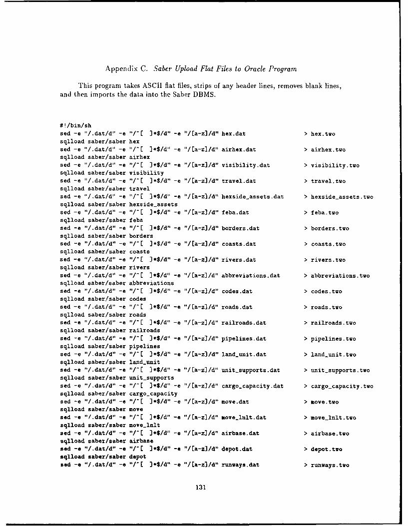
Appendix C. Saber Upload Flat Files to Oracle Program
This program takes ASCII flat files, strips of any header lines, removes blank lines,and then imports the data into the Saber DBMS.
V Ibin/shsed -e "/.dat/d" -e fl/-[ J*$/d" -e "/[a-z]/d' hex.dat > hex.twosqiload saber/saber hexsed -e "/.dat/d" -e $/-[ )*$/d" -e "/Ea-z)/d" airhex.dat > airhex.twosqiload saber/saber airhexsed -e "/.dat/d" -e "/-[ J*$/d" -e "/Ea-z)/d" visibility.dat > visibility.twosqiload saber/saber visibilitysed -e '/.dat/d" -e 'I/-[ ]*$/d" -e "/[a-z]/d" travel.dat > travel.twosqiload saber/saber travelsed -e "/.dat/d" -e '"/-[ 3*$/d" -e "/Ea-z]/d" hexside-assets.dat > hexside-assets.twosqiload saber/saber hexside-assetssed -e "/.dat/d" -e fl/-[ J*$/d" -e "/[a-z)/d" feba.dat > feba.twosqiload saber/saber febasod -e '/.dat/d" -e "/-[ )*$/d" -e '/[a-z]/d" borders.dat > borders.twosqiload saber/saber borderssed -e '/.dat/d" -e "/-[ )e$/d" -e "/Ea-z]/d" coasts.dat > coasts.twosqiload saber/saber coastssed -e "/.dat/d" -e "/-[ J*$/dll -e "/[a-z)/d" rivers.dat > rivers.twosqiload saber/saber riverssed -e "/.dat/d" -e ls/E ]*$/d" -e "/[a-z]/d' abbreviations.dat > abbreviations.tvosqiload saber/saber abbreviationssed -e '/.dat/d" -e ,/-[ ]*$/d" -e "/Ea-z]/d" codes.dat > codes.tvosqiload saber/saber codessed -e "/.dat/d" -e "/-[ )e$/d' -e "/Ca-z)/d" roads.dat > roads.twosqiload saber/saber roadssed -e fl/ .dat/d" -e "/- [ ) e$/d" -e "/ a-zJ /d" railroads .dat > railroads. tvosqiload saber/saber railroadssed -e "/.dat/d" -e "/-[ ]*$/d" -e "/Ea-z]/d" pipelines.dat > pipelines.twosqiload saber/saber pipelines
sed -e "/.dat/d' -e "/-[ ]*$/d" -e "/Ea-z]/d" land-.unit.dat > laxid-.unit.twosqlload saber/saber land-.unitsed -e '/.dat/d" -e "/-[ ]*$/d" -e "/Ea-zJ/d" unit..supports.dat > unit..supports.tuosqlload saber/saber unit-.supportssed -e '/.dat/d' -e 04/-[ ]*$/d" -e "/[a-z]/d" cargo-.capacity.dat > cargo..capacity.tvosqlload saber/saber cargo-.capacitysod -e "/.dat/d9 -e "/-[ ]*$/d" -e "/[a-z)/d" move.dat > move.twosqlload saber/saber movesod -e "/ .dat/d" -e 0'/- J*$/d" -e '/Ca-zJ/d" movelinlt.dat > move-.lnlt.twosqlload saber/saber move-.lnltsod -e "/.dat/d" -e #$/[ J*$/d' -e "/[a-z)/d" airbase.dat > airbase.twosqlload saber/saber airbasesod -s "/.dat/d" -e 'I/-[ J$/d" -e "/Ea-z)/d" depot.dat > depot.twosqlload saber/saber depotsod -e "/.dat/d" -e "/-[ )*$/d" -e "/Ea-z)/d" runways.dat > runways.two
131
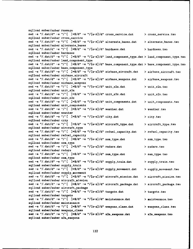
sqiload saber/saber runways
sed -e "/.dat/d" -e "/-[ ]*$/d" -e II/[a..z)/dI cross-.service.dat > cross-service.twosqiload saber/saber cross-servicesed -e "/.dat/d" -e "/-[ J*$/d" -e "/Ea-z]/d" alternate-.bases.dat > alternate-bases.twosqiload saber/saber alternate-basessed -e "/.dat/d" -e "/-[ ]*$/d" -e '/Ca-z]/d" hardness.dat > hardness.twosqiload saber/saber hardnesssed -e "/.dat/d" -e 01/[C *$/d' -e '/Ca-z]/d" land..component..type.dat > land-component-type.twosqiload saber/saber land-component-.typesed -e "I. dat/d" -e '/-C ] *$/d" -e '/ Ea-z] Id" base-.component..type .dat > base..component-type .twosqiload saber/saber base-.component-.typesed -e "/.dat/d" -e "/-[ )*$/d" -e '/[a-z)/d' airbase-aircraft.dat > airbase-aircraft.twosqlload saber/saber airbase..aircraftsed -e '/.dat/d" -e "/-[ ]*$/d" -e "/[a-z]/d" airbase-weapons.dat > airbase-weapons.twosqiload saber/saber airbase-weaponssed -e "/.dat/d" -e "/- ]*$/d" -e "/[Ca-z] /d" unit-s2a.dat > unit-s2a.twosqiload saber/saber unit-s2ased -e "/.dat/d" -e 0'/E[ ]*$/d" -e "/[a-z]/d" unit-s2s.dat > unit..s2s.twosqiload saber/saber unit-s2ssed -e "/.dat/d" -e "/[C ]*$/d" -e "/a-z] /d" unit.components.dat > unit.components.twosqiload saber/saber unit-componentssed -e "/.dat/d" -e "/-[ )*$/d" -e C/a-z) /d" veather.dat > weather.twosqiload saber/saber weathersed -e "/.dat/d' -e I'/-C )*$/d" -e "/a-z] /d" city.dat > city.twosqiload saber/saber citysed -e '/.dat/d" -e "/-( ]*$/d" -e "/Ea-z]/d" aircraft-.type.dat > aircraft-type.twosqiload saber/saber aircraft-typesed -e '/.dat/d" -e 10/- ]*$/d" -e '/Ca-z)/d" refuel-capacity.dat > refuel-capacity.twosqiload saber/saber refuel-capacitysed -e "/.dat/d" -e "/-[ )*$/d" -e V/Ca-z) /d" ssm..type.dat > ssm-type.twosqlload saber/saber ssm-typesed -e "/.dat/d" -e I'/-[ )*$/d" -e V/Ca-z] /d" radars.dat > radars.twosqiload saber/saber radarssed -e "/.dat/d" -e "/-[ ]*$/d" -e "/[a-z]/d" sam-.type.dat > sam-type.twosqiload saber/saber sam-typesed -e "/.dat/d" -e "/-[ 3*$/d" -e V/Ca-z] /d" supply...train.dat > supply-train.twosqiload saber/saber supply-.trainsed -e "/.dat/d" -e "/-[ ]*$/di" -e "/Ea-z]/d" supply-.movement.dat > supply-movement.twosqiload saber/saber supply-movementsed -e "/.dat/d" -e "/-[ )*$/d" -e "/Ca-z)/d" aircraft-mission.dat > ajrcraft-mssion.twosqiload saber/saber aircraft-missionsed -e "/.dat/d" -e go/- ]*S/d"l -e "/Ca-z)/d" aircraft-package.dat > aircrait-package.twosqiload saber/saber aircraft-packagesed -e "/.dat/d" -e "/PC )*$/d'a -e "/[a-z)/d" targets.dat > targets.twosqiload saber/saber targetssod. -e "/.dat/d" -e "/-[ 3*/dn -e "/[a-z3/d" maintexiance.dat > maintenance.twosqiload saber/saber maintenancesed -e '/.dat/d" -e "/PC ]*$/d" -e "/Ca-z)/d" weapons-class.dat > weapons-.class.twosqiload saber/saber weapons-classsod -e "/.dat/d" -e "/P[ ]*$/d" -e "/Ea-z)/d" a2a..weapons.dat > a2&..weapons.twosqlload saber/saber a2a-weapons
132
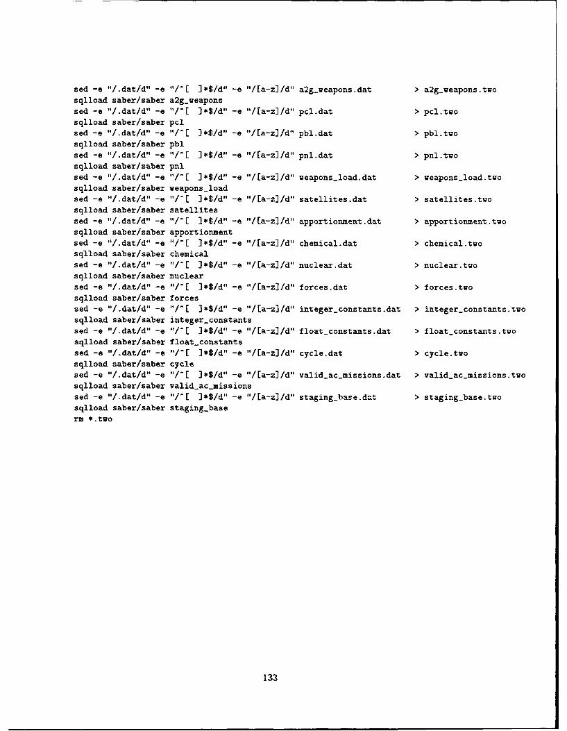
sed -e "I. dat/d" -e "/-[ ] *$/do' -e --/Ea-z] I a2g-.weapons .dat >a2g-weapons .twosqiload saber/saber a2g-.weaponssed -e "/.dat/d" -e "/-[ )*$/d"' -e "/Ea-zJ/d" pcl-dat > pcl.twosqiload saber/saber pcised -e "/.dat/d" -e "/-[ ]*$/do' -e "/[a-z]/d' pbl.dat > pbl.twosqiload saber/saber pblsed -e "/.dat/d" -e "/-[ ]*$/do' -e "/Ea-z)/d" pnl-dat > pnl.twosqlload saber/saber pnlsed -e "/.dat/d" -e "/-[ ]*$/d' -e "I/Ea-z]/d" weapons.load.dat > weapons-load.twosqiload saber/saber weapons-loadsed -e '/.dat/d' -e "/-[ ]*$/do' -e "/[a-zJ/d" satellites.dat > satellites.twosqiload saber/saber satellitessed -e "/.dat/d" -e "/[C J*$/do' -e "/[a-zl/d' apportiotnent.dat > apportionment.twosqiload saber/saber apportionment
sed -e V/dat/d" -e "/-[ ]*$/d"' -e "I/[a-zJ/d" chemical.dat > chemical.twosqiload saber/saber chemical
sed -e "/.dat/d" -e "/-[ ]*$/d' -e "/[a-z]/d" nuclear.dat, > nuclear.twosqiload saber/saber nuclear
sed -e "/.dat/d"I -e "/-[ ]*$/d' -e "/[a-z]/d" forces.dat > forces.twosqiload saber/saber forcessed -e '/.dat/d" -e "/-[ )*$/d" -e "/La-z]/d" integer-constants.dat > integer-.constants.twosqiload saber/saber integer-.constants
sed -e "/.dat/d' -e 'I/-[ ]*$/d"' -e 01/Ea-z]/d" float-constants.dat > float-constants.twosqiload saber/saber iloatsconstants
sed -e "/.dat/d" -e --/-[ ]*$/d' -e "/[a-z)/d" cycle.dat > cycle.two
sqiload saber/saber cyclesed -e '/.dat/d" -e Is/-[ ]*$/do' -e "/Ea-z)/d" valid..ac~missions-dat > valid-ac-missions.tuosqlload saber/saber valid.ac-.missions
sed -e "I/.dat/dI" -e It/-[ ]*$/d"' -e "/Ea-z]/d" staging-base.dat > staging..base.two
sqlload saber/saber staging-.base
irn *.two
133
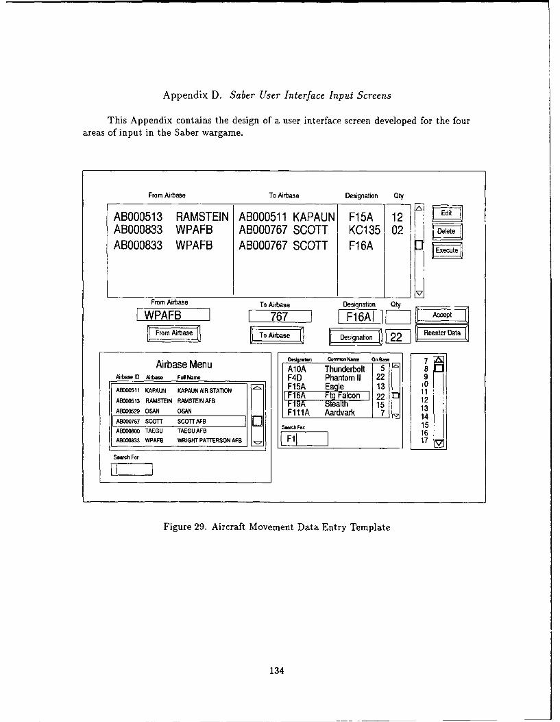
Appendix D. Saber User Interface Input Screens
This Appendix contains the design of a user interface screen developed for the fourareas of input in the Saber wargame.
From Airbase To Airbase Designation Qty
ABOO0513 RAMSTEIN ABOO0511 KAPAUN F15A 12ABOO0833 WPAFB ABO00767 SCOTT KCl 35 I02 DltAB000833 WPAFB ABO00767 SCOTT F1 6A
________________________ 17From Airbase To Airbase Designation QtyIWPAFB71 767 -1 1F16AI "I p
ODaigmton Con Norm OrBass 7Airbase Menu A10A Thunderbolt 5 8
Airbase I0 Aubase Ful Narm F4D) Phantom 11 22 9
ABOCO1i KAPAUN KAPAUN AIR STATION FiS Ea lo 13 22 0 1ABM0013 RAIVSTEIN RAIVSTEIN AFB 16o 212II 1F9 SIbtean 15 H 13ABOO0529 OA SNF111A Aardvark 7_? 1ABDO0767 SCOTT SCOTT AFB Serc Fr 15A8000800 TAEGU TAEGU AFB K whFr16
AB000833 WPAFB WRIGHT PATTERSON AFB Fl17
Search For
Figure 29. Aircraft Movement Data Entry Template
134
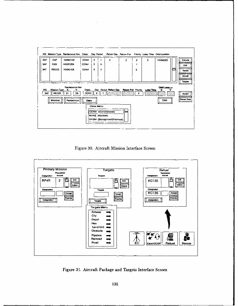
HO Mission Type Rendezvous Hex Clas Day Period Return Day Return Prd Priority Loiter T"n Orbit Locatin
5AF CAP HX042 128 CONV 3 1 3 2 2 2 HX042025 Eiieouii
3AF CAS HX031 226 CONy 2 3 1 Edit
3AF RECCE HX042128 CONy 3 1 2 3 E
Rendezvous Hex COtbUL~.nHO MisonTp X V Ctass Do Period trns Retrn Prd Prort Lo~it Xhi X
3AF 11 [~ RECC FCONy i ]LVi ~ I
Class IMenu
CONV (Conventiona) [ r3NUKE (Nuclear)
CH EM (Biotogincal/Chemlicaj) L
Figure 30. Aircraft Mission Interface Screen
Primary Mission Targets RefuelRtum0ted Ftqumeuid
Oeignslon Aliioeft Deepe Oson Akcal
RF4R 2 1E3KC135
De g nue n Ter "es Oe ow -ie i E ]
Targets Mentu
Airbase niilCity No
Depot 111111Land Unit uni
Obstacle 0
Pipeine viij
Railroad amRoad 2-1EC Eselue ReAP
Figure 31. Aircraft Package and Targets Interface Screen
135
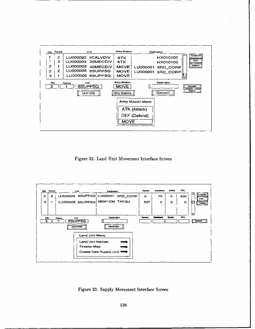
Day Period Unit Army Mission Destination
1 2 LUooooo2 1ALVDIV ATK HX010102i 2 LU000003 35MECDIV ATK HX010103 Edit
2 1 LUO00003 35MECDIV MOVE LU000001 3RD CORP K2 2 LUOO006 6SUPPSQ MOVE LUOOO0 3RDCORP3 1 LU000006 6SUPPSQ MOVE
Day Period Unit Army Mission Destination
LILJZ[i! 6SUPPSQ [MOVE Acc
r 5 rssionsOno DR
Army Mission Menu
ATK (Attack)DEF (Defend)MOVE
Figure 32. Land Unit Movement Interface Screen
Oy Priod Unit DOwfnao n SP. Hardear. Arno POL
2 2 LU000006 6SUPPSO LU000001 3RDCORP 0 75 0 400
* 1 LU000006 6SUPPSQ AB001234 TAEGU 527 0 0 0
Day P.006 Unit a ~lS fl s ftS Amwm POLS 3 II s ] p - I11}I -]- I- - = a
Land Unit Menu
Land Unit Name1
Theater Map
Create New Supply Unit
Figure 33. Supply Movement Interface Screen
136
Bibliography
1. Air Force Wargaming Center, Air University, Maxwell AFB, fA!abama. AGILE '89Theater War Exercise Computer Operator's Handbook, 1989.
2. Berlage, Thomas. OSF/Motif Concepts and Programming. Workingham, England:Addision-Wesley Publishing Company, 1991.
3. Blake, Bernard H, editor. Jane's Weapon Systems. Surrey, UK: Jane's InformationGroup, 1989.
4. Cheu, Dwight. SQL Language Reference Manual Version 6.0. Oracle Corporation,Belmont, California, 1989.
5. Colston, Lisa. SQL *Plus Users' Guide and Reference Version 3.0. Oracle Corpora-tion, Belmont, California, 1989.
6. Date, C.J. An Introduction to Database Systems (3 Edition), 1. Reading, Mas-sachusets: Addison-Wesley Publishing Company, 1982.
7. Dunnigan, James F. The Complete Wargames Handbook. New York: William Morrowand Company, Inc., 1980.
8. Dunnigan, James F. How to Make War. New York: William Morrow and Company,Inc., 1988.
9. Ellison, Lawrence. ORACLE Overview and Introduction to SQL. Oracle Corporation,Belmont, California, 1985.
10. Finn, Richard M. CRES Theater Game Requirements. Technical Report. MaxwellAFB, Alabama, 1989.
11. J-8, The Joint Staff, PMAD. Theater Analysis Model(TAM) AirLand Campaign ModelUser's Manual, 1990.
12. Johnson, Eric and Kevin Reichard. Power Programming... Motif. Portland, OR:Management Information Source, Inc., 1991.
13. Johnson, Eric F. and Kevin Reichard. X Window Applications Programming. Port-land, Oregon: Management Information Source Press, 1989.
14. Jones, Oliver. Introduction to the X Window System. Englewood Cliffs, New Jersey:Prentice-Hall, 1988.
15. Jr., James Dornan, editor. The US War Machine. Surrey, UK: Crown Publishers,Inc., 1978.
16. Klabunde, Gary W. An Ada-based Graphical Postprocessor for the Saber Wargame.MS thesis, School of Engineering, Air Force Institute of Technology (AU), Wright-Patterson AFB OH, December 1991.
17. Klein, Daniel and Donna Neville. Pro *Ada Prcompiler. Oracle Corporation, Belmont,California, 1987.
137
18. Korb, Edward L., editor. The World's Missile Systems. Pomona, California: General
Dynamics, 1982.
19. Korth, Henry F. and Abraham Silberschatz. Database System Concepts. New York:McGraw-Hill Publishing Company, 1986.
20. Kross, Mark S. Developing New User Interfaces for the Theater War Exercise.MS thesis, School of Engineering, Air Force Institute of Technology (AU), Wright-Patterson AFB OH, December 1987.
21. Lower, Stephen L. The Development of Visual Interface Enhancements For PlayerInput to the JTLS Wargame. MS thesis, Navy Postgraduate School, Monterey, CA,
March 1987.
22. Mann, William F. Saber - A Theater Level Wargame. MS thesis, School of Engi-neering, Air Force Institute of Technology (AU), Wright-Patterson AFB OH, March1991.
23. McGilton, Henry and Rachel Morgan. Introducing the UNIX System. New York, NewYork: McGraw-Hill Book Company, 1983.
24. Moran, Rita and Shelly Dimmick. SQL*Loader User's Guide Version 1.0. Oracle
Corporation, Belmont, California, 1989.
25. Ness, Marlin A. A New Land Battle for the Theater War Exercise. MS thesis, Schoolof Engineering, Air Force Institute of Technology (AU), Wright-Patterson AFB OH,June 1990.
26. Nye, Adrian. Xlib Reference Manual for Version 11. Massachusetts: O'Reilly andAssociates, Inc, 1988.
27. Open Systems Foundation, Englewood Cliffs, New Jersey. OSF/Motif Programmers
Reference, 1990.
28. Rettig, Marc. "5 Rules of Data Normalization," Database Programming and Design
(1990). Poster.
29. Scheifler, Robert W. and others. X Window System - C Library and Protocol Refer-ence. Massachusetts: Digital Press, 1988.
30. Sherry, Christine M. Saber - A Theater Level Wargame Design and Implementation.MS thesis, School of Engineering, Air Force Institute of Technology (AU), Wright-Patterson AFB OH, December 1991.
31. Shneiderman, Ben. Designing the User Interface: Strategies for Effective Human-
Computer Interaction. Reading, Massachusetts: Addison-Wesley Publishing Com-pany, 1986.
32. Smith, Sidney L. and J,-ne N. Mosier. Guidelines for Designing User Inteface Soft-
ware. DTIC AD-A177 198, Bedford, Massachusetts: Mitre, 1986.
33. Sommerville, Ian. Software Engineering. Wokingham, England: Addison-WesleyPublishing Company, 1989.
138
34. Stevens, Nora G. The Application of Current User Interface Technology to Inter-active Wargaming Systems. MS thesis, Navy Postgraduate School, Monterey, CA,September 1987.
35. Taylor, John W., editor. Jane's Military Vehicles and Ground Support Equipment.Surrey, UK: Jane's Information Group, 1987.
36. Taylor, John W., editor. Jane's All the World's Aircraft. Surrey, UK: Jane's Infor-mation Group, 1989.
37. Walker, Swen. Database Design and Land Battle Interface for the Fast Stick Exercise.MS thesis, School of Engineering, Air Force Institute of Technology (AU), Wright-Patterson AFB OH, December 1988.
38. Wilcox, Kenneth. Extending the User Interface for the Theater War Exercise.MS thesis, School of Engineering, Air Force Institute of Technology (AU), Wright-Patterson AFB OH, December 1988.
39. Young, Douglas A. X Window Systems: Programming and Applications with Xt.Englewood Cliffs, New Jersey: Prentice Hall, 1989.
139
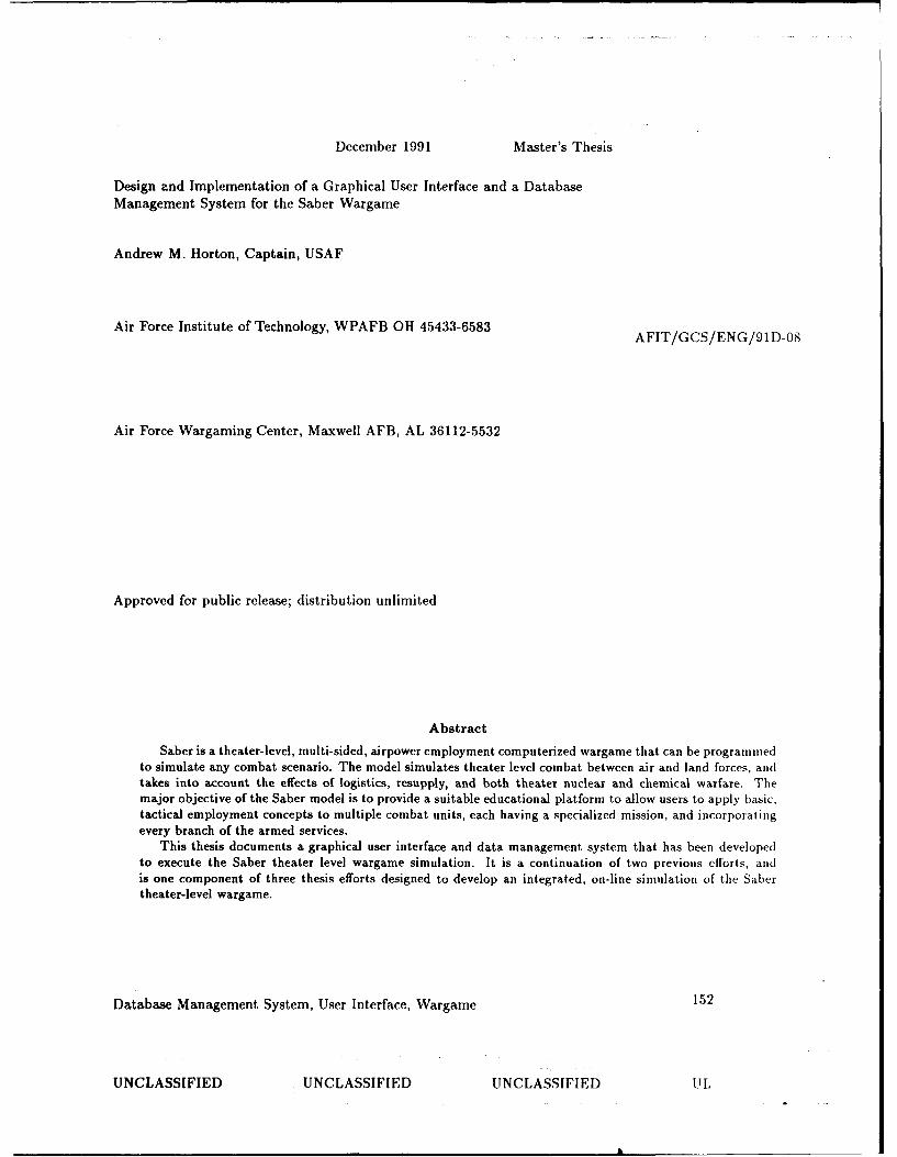
December 1991 Master's Thesis
Design and Implementation of a Graphical User Interface and a DatabaseManagement System for the Saber Wargame
Andrew M. Horton, Captain, USAF
Air Force Institute of Technology, WPAFB OH 45433-6583 AFIT/GCS/ENG/91D-08
Air Force Wargaming Center, Maxwell AFB, AL 36112-5532
Approved for public release; distribution unlimited
Abstract
Saber is a theater-level, multi-sided, airpower employment computerized wargame that can be programmedto simulate any combat scenario. The model simulates theater level combat between air and land forces, andtakes into account the effects of logistics, resupply, and both theater nuclear and chemical warfare. Themajor objective of the Saber model is to provide a suitable educational platform to allow users to apply basic.tactical employment concepts to multiple combat units, each having a specialized mission, and incorporatingevery branch of the armed services.
This thesis documents a graphical user interface and data management system that has been developedto execute the Saber theater level wargame simulation. It is a continuation of two previous efforts, andis one component of three thesis efforts designed to develop an integrated, on-line simulation of the Sabertheater-level wargame.
Database Management System, User Interface, Wargame 152
UNCLASSIFIED UNCLASSIFIED UNCLASSIFIED I L
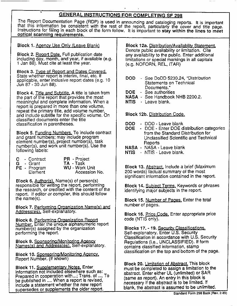
GENERAL INSTRUCTIONS FOR C0OMPLETING SF 298
The Report Documentation Page (RDP) is used in announcing and cataloging reports. It is importantthat this information be consistent with the rest of the report, particularly the cover and title page.Instructions for filling in each block of the form follow. It is important to stay within the lines to meetoptical scanning requirements.
Block 1. Aaencv Use Only (Leave Blank) Block 12a. Distribution/Availablity Statement.Denote public availability or limitation. Cite
Block 2. Report Date, Full publication date any availability to the public. Enter additionalincluding day, month, and year, if available (e.g. limitations or special markings in all capitals1 Jan 88). Must cite at least the year. (e.g. NOFORN, REL, ITAR)
Block 3. Type of Re~ort and Dates Covered.State whether report is interim, final, etc. If DOD - See DoDD 5230.24, "Distributionapplicable, enter inclusive report dates (e.g. 10 Seenon TechnialJun 87 - 30 Jun 88). Statements on Technical
Documents."
Block 4. Title and Subtitle. A title is taken from DOE - See authoritiesthe part of the report that provides the most NASA - See Handbook NHB 2200.2.meaningful and complete information. When a NTIS - Leave blank.report is prepared in more than one volume,repeat the primary title, add volume number,and include subtitle for the specific volume. On Block 12b. Distribution Code.classified documents enter the titleclassification in parentheses. DOD - DOD - Leave blank
DOE - DOE - Enter DOE distribution categoriesBlock 5. Funding Numbers. To include contract from the Standard Distribution forand grant numbers; may include program Unclassified Scientific and Technicalelement number(s), project number(s), task Reportsnumber(s), and work unit number(s). Use the NASA - NASA - Leave blankfollowing labels: NTIS - NTIS - Leave blank.
C - Contract PR - ProjectG - Grant TA -TaskPE - Program WU - Work Unit Block 13. Abstract, Include a brief (Maximum
Element Accession No. 200 words) factual summary of the mostsignificant information contained in the report.
Block 6. Author(s). Name(s) of person(s)responsible for writing the report, performing Block 14. Subject Terms, Keywords or phrasesthe research, or credited with the content of the identifying major subjects in the report.report. If editor or compiler, this should followthe name(s). Block 15. Number of Pagies. Enter the total
Block 7. Performing Organization Name(s) and number of pages.Addressfes) Self-explanatory. Block 16. Price Code, Enter appropriate price
Block 8. Performing Organization Reoort code (NTIS only).Number, Enter the unique alphanumeric reportnumber(s) assigned by the organization Blocks 17.- 19. Security Classifications.performing the report. Self-explanatory. Enter U.S. Security
Classification in accordance with U.S. SecurityBlock 9. Sponsorina/Monitorirg Agency Regulations (i.e., UNCLASSIFIED). If form_Names(s) and Address(es). Self-explanatory. contains classified information, stamp
Block 10. Sp2onsoring/Monitoring Agency. classification on the top and bottom of the page.
Report Number. (If known)Block 20. Limitation of Abstract. This blockBlock 11. SuoolementarY Notes. Enter must be completed to assign a limitation to the
information not included elsewhere such as: must be ete to a nlimitedo o the
Prepared in cooperation with...; Trans. of ..., To abstract. Enter either UL (unlimited) or SAR
be published in .... When a report is revised, (same as report). An entry in this block is
include a statement whether the new report necessary if the abstract is to be limited. If
supersedes or supplements the older report. blank, the abstract is assumed to be unlimited.Standard Form 298 Back (Rev. 2-89)