Embed Size (px)
Citation preview
Journal of Theoretical and Applied Information Technology 10
th August 2014. Vol. 66 No.1
© 2005 - 2014 JATIT & LLS. All rights reserved.
ISSN: 1992-8645 www.jatit.org E-ISSN: 1817-3195
340
HIGH PERFORMANCE SEVEN LEVEL ACTIVE SHUNT
FILTER FOR HARMONIC MITIGATION
1S.LEELA,
2S.S.DASH
1 Assistant Professor, Dept.of Electrical & Electronics Engg., SRC, Sastra University, Tamilnadu, India 2 Professor, Department of Electrical & Electronics Engineering, SRM University, Tamilnadu, India.
E-mail: [email protected] , [email protected]
ABSTRACT
This paper deals with the simulation of a shunt active filter using seven level cascaded H-bridge multilevel inverter. The proposed active filter topology can also produce seven voltage levels, which significantly reduces the switching current ripple and the size of passive components. The seven level active shunt filter provides compensation of load power factor and current harmonics. For compensation current extraction, synchronous detection method has been used. The harmonic reduction is achieved in source currents as well as source voltages. Circuit model is developed and the same is used for simulation studies. The effectiveness of the proposed control technique is verified by the simulation results.
Keywords: Matlab simulink, Pulse Width Modulation, Seven level inverter, Shunt active filter, Total
Harmonic Distortion.
1. INTRODUCTION Power electronics based devices such as adjustable speed drives (ASDs), uninterruptible power supplies (UPSs) and static var compensators (SVCs) are widely employed in various applications now-a-days. These devices draw current with harmonic content and reactive power from ac mains due to their nonlinear V-I characteristics. Current harmonics drawn by non linear loads disturb the waveform of the voltage at the point of common coupling (PCC) and lead to the voltage harmonics which the other linear loads and sensitive electronic equipments have to deal with. Normally, passive LC filters and capacitor banks were used to reduce harmonics and to improve power factor of the ac loads. The limitations encountered here includes large size and weight, fixed compensation design, increased operating losses and risk of resonance occurrence. A dynamic and adjustable solution to these power quality problems gave rise to the new concept of active power filter (APF) also called as active power line conditioner (APLC) or active power quality conditioner (APQC) being introduced first a couple of decade ago by Gyugi and Strycula [1]. With the emergence of
semiconductor devices which includes IGBTs and MOSFETs having the advantage of fast switching capability, and the availability of digital signal processors (DSPs), field programmable gate arrays (FPGAs), hall effect voltage/current sensors at reasonable cost, the usage of active power filters has become widespread. Presently active power filters have the advantages of being smallier in size, flexible in operation and in filtering performance, compared to traditional passive filters. However the APFs have still the disadvantages of higher cost and complexity of control [2]. To improve the power quality, the active power filters have proved to be an important alternative to compensate for current and voltage disturbances in power distribution systems [3], [4], [5]. Various active power filters topologies have been presented in [6] [7] and many of them are already available in the market.
Among the different active power filter configurations, Shunt Active Power Filter finds pronounced applications in industrial processes. It is connected in parallel with the non-linear load as shown in Fig. 1. The main purpose of the filter is to cancel the load current harmonics

Journal of Theoretical and Applied Information Technology 10
th August 2014. Vol. 66 No.1
© 2005 - 2014 JATIT & LLS. All rights reserved.
ISSN: 1992-8645 www.jatit.org E-ISSN: 1817-3195
341
injected to the supply but it can also implement reactive power compensation.
Fig.1. Block Diagram Of Shunt Active
Power Filter.
Active power filters may be either single phase or three phase active filters. Single phase APFs are limited to low power applications. However, installing low power single phase APF near each single phase non-linear load may be sometimes a better solution than installing one medium power three phase APF at the point of common coupling due to simplicity of control without complex heavy mathematical equations and decrease in cost of APF from medium to low power. Three phase APFs are employed for high power applications. The experimental verification of dominant harmonic active filter for high power applications was given by Cheng [8]. The modern active filters and traditional passive filters was given by Akagi [9]. The performance improvement of active power filters based on P-Q and D-Q control methods under non-ideal supply voltage conditions was given by Biricik [10]. The above literature does not deal with the modelling of shunt active filter using seven level cascaded H-bridge multilevel inverter system using matlab simulink. In this work, an attempt is made to model and simulate the shunt active filter using seven level cacaded H-bridge multilevel inverter system using simulink. For compensation current extraction, synchronous detection method has been used.
2. THREE PHASE SEVEN LEVEL
CASCADED H-BRIDGE MULTI
LEVEL INVERTER
This section presents a Shunt Active Power Filter in power system application. It is implemented with multiple single-phase cells connected in series combination as shown in Fig. 2. Each cell consists of a DC capacitor and a full–bridge single-phase PWM-VSI. By employing this configuration, higher voltage levels can be obtained. Also medium and high voltage power systems can be compensated. For the purpose of isolation in each phase an inductive reactor is connected between the line and Shunt Active Power Filter. For improving the performance characteristics of the system, each power cell is operated at different DC voltage and constant switching frequency. The switching speed and voltage capability of semiconductor switches used in the system gives the total number of inverters to be connected in series in each phase to compensate the harmonic currents for a given medium voltage power system. The operating voltage of each cell depends on the number of cells and the total voltage that is to be delivered by the modular inverter. With the combination of 3 kV and 1.5 kV DC bus voltages in this configuration, the stepped waveforms with seven voltage levels via. -4.5 kV, -3 kV, -1.5 kV, 0, 1.5 kV, 3 kV, 4.5 kV at the output of each phase leg are synthesized. As shown in Fig.2, the inverters employing GTO’s are used to synthesize higher voltage levels (±3kV) and the inverters employing IGBT’s are used to synthesize lower voltage levels (± 1.5kV).
Fig.2. Schematic Diagram Of Seven
Level Cascaded H-Bridge Multi
Level Inverter

Journal of Theoretical and Applied Information Technology 10
th August 2014. Vol. 66 No.1
© 2005 - 2014 JATIT & LLS. All rights reserved.
ISSN: 1992-8645 www.jatit.org E-ISSN: 1817-3195
342
Since the switching capability of GTO thyristors are limited at high frequencies, a hybrid strategy which incorporates stepped synthesis in conjunction with variable pulse width of the consecutive steps is proposed. The seven level H-bridge inverter for three phase proposed in this paper is shown in Fig.3. There are individual capacitors for each H-bridge module. There are N voltage sources per phase for a 2N + 1 level inverter. The principal characteristic of the cascaded (modular) topology is suitable for high voltage power system applications. The modulation strategy forms the core part of the pulse generation to the inverter. It should meet the following advantages like voltage balancing, reduced harmonic content. The multicarrier PWM technique is chosen here because of its easiness in implementation, reduction in switching losses and low harmonic content. Further more the multicarrier PWM is classified as level shifted (vertical arrangement of carriers) and phase shifted (horizontal arrangement of carriers). In this work, phase disposition method is implemented for the pulse generation in hybrid MLI topology along with triangular periodic controller.
Fig.3. Proposed Three Phase Seven
Level H-Bridge Inverter
Fig.4 shows multi carrier PWM with carrier frequency 10kHZ. The switching for the hybrid MLI is generated through the triangular periodic controller. This controller compares the reference signal with the actual signal. Then an error is generated. The received error signal is processed through the Proportional controller to reduce the error followed by the comparison with level shifted carriers (PD). The switching pulses thus obtained are fed to the hybrid MLI.
Fig.4. Multi Carrier Pwm With Carrier
Frequency 10khz
3. ACTIVE SHUNT FILTER
Shunt Active Filter acts as a current source. At the point of common coupling, it injects equal but opposite harmonic and quadrature components of load current. The Shunt Active Filter is nothing but a PWM Voltage Source Inverter operating as a current controlled device. Here multi-level inverter is used for high power energy conversion. The multilevel inverters do not need a coupling transformer to interface it with high power system. Fig.5 shows the schematic diagram of the shunt active power filter.
Fig.5. Schematic Diagram Of The Shunt
Active Power Filter
The time domain approach involves the Synchronous-Detection Method (SDM). The three phase currents are sinusoidal and balanced. They are in phase with the source voltages irrespective of the load variations. Accordingly, the average power is calculated and divided equally between the three phases. In respect to the supply voltage the signal is then synchronized for each phase. The average real power consumed by the load with respect to the three phases gives the desired mains currents, assuming that they are balanced and are in phase with the supply voltages after compensation. The difference between the load currents and the desired mains currents gives the reference

Journal of Theoretical and Applied Information Technology 10
th August 2014. Vol. 66 No.1
© 2005 - 2014 JATIT & LLS. All rights reserved.
ISSN: 1992-8645 www.jatit.org E-ISSN: 1817-3195
343
compensation signals. The compensating currents are calculated taking into account the magnitudes of per phase voltages. The amplitude of the source currents are determined using Synchronous Detection Method. In this algorithm, the three-phase mains currents are assumed to be balanced after compensation. The real power P(t) consumed by the load is calculated from the instantaneous voltages and load currents as:
( ) [ ] [ ]TlclblascsbsaIIIVVVtP *= (1)
where Vsa(t), Vsb(t), Vsc(t) are the instantaneous values of supply voltages and Ila(t), Ilb(t), Ilc(t) are the instantaneous values of load currents. The average value Pdc is determined by
applying P(t) to a low pass filter.
The real power is split into three phases Pa, Pb, Pc. Hence we have
[ ]
[ ]crmsbrmsarms
armsdc
a
VVV
VPP
++
=
* (2)
[ ]
[ ]crmsbrmsarms
brmsdc
b
VVV
VPP
++
=
* (3)
[ ]
[ ]crmsbrmsarms
crmsdc
c
VVV
VPP
++
=
* (4)
For purely sinusoidal balanced supply
voltages,
3
dc
cba
PPPP === (5)
For achieving unity power factor the desired mains currents are obtained by equations:
( )[ ]2
**2
arms
asa
sa
V
PtVI = (6)
( )[ ]2
**2
brms
bsb
sb
V
PtVI = (7)
( )[ ]2
**2
crms
csc
sc
V
PtVI = (8)
where 222
&&crmsbrmsarms
VVV are the
amplitudes of the three supply voltages resp. The compensating currents are:
( ) ( ) ( )tItItIsalaca
−= (9)
( ) ( ) ( )tItItIsblbcb
−= (10)
( ) ( ) ( )tItItIsclccc
−= (11)
4. SIMULATION RESULTS
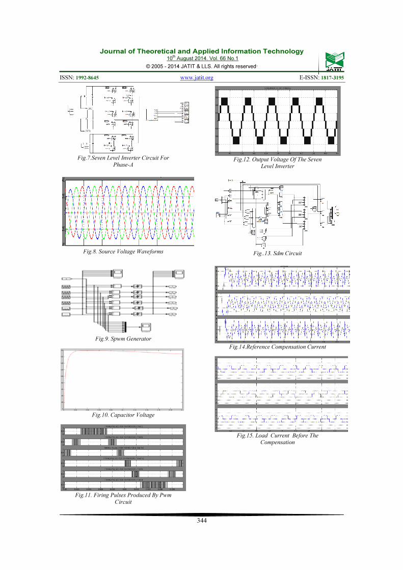
Digital simulation is done using the blocks of Matlab simulink and the results are presented here. The simulation diagram of Seven Level Active Shunt Filter is shown in Fig.6. The simulation circuit consists of a three phase balanced source, Non Linear Load, SDM circuit for compensation current extraction, PWM circuit for generating gate pulse and seven level inverter. The seven level inverter circuit for phase-a is shown in Fig.7. The source voltage waveforms is shown in Fig.8. The SPWM generator is shown in Fig.9. The capacitor voltage is shown in Fig.10. The firing pulses produced by PWM circuit is shown in Fig.11. The output voltage of the seven level inverter is shown in Fig.12. The SDM circuit is shown in Fig.13. The reference compensation current is shown in Fig.14. The load current before compensation is shown in Fig.15. The source current before and after compensation is shown in Fig.16. The FFT analysis of the load current before compensation is shown in Fig.17. The THD is 30.51%.The FFT analysis of the source current after compensation is shown in Fig.18. The THD is 4.48%. Thus the harmonics are reduced from 30.51% to 4.48%.
Fig.6. Simulation Diagram Of Seven
Level Active Shunt Filter
Journal of Theoretical and Applied Information Technology 10
th August 2014. Vol. 66 No.1
© 2005 - 2014 JATIT & LLS. All rights reserved.
ISSN: 1992-8645 www.jatit.org E-ISSN: 1817-3195
344
Fig.7.Seven Level Inverter Circuit For
Phase-A
Fig.8. Source Voltage Waveforms
Fig.9. Spwm Generator
Fig.10. Capacitor Voltage
Fig.11. Firing Pulses Produced By Pwm
Circuit
Fig.12. Output Voltage Of The Seven Level Inverter
Fig..13. Sdm Circuit
Fig.14.Reference Compensation Current
Fig.15. Load Current Before The
Compensation

Journal of Theoretical and Applied Information Technology 10
th August 2014. Vol. 66 No.1
© 2005 - 2014 JATIT & LLS. All rights reserved.
ISSN: 1992-8645 www.jatit.org E-ISSN: 1817-3195
345
Fig.16. Source Current Before And After
Compensation
Fig.17. Fft Analysis Of Load Current
Before Compensation
Fig.18. Fft Analysis Of Source Current
After Compensation
5. CONCLUSION
The shunt active filter using seven level cascaded H-bridge multilevel inverter is
modelled and simulated using matlab simulink. The voltage stresses on each switch is decreased due to series connection of switches. Also the rate of change of voltage is decreased. The harmonic distortion is reduced due to more output levels. The Electromagnetic interference effects and acoustic noise are lowered. The contribution of this work is that the THD is reduced in source current from 30.51% to 4.48%. Thus by using shunt active filter using seven level cascaded H-bridge multilevel inverter the power quality is improved. The heating is reduced due to the harmonic reduction in source currents as well as source voltages. The simulation results are in line with the predictions.
REFERENCES [1] L. Gyugyi, E.C.Strycula ,“Active AC Power Filters”, Proc. IEEE/IAS Annual Meeting,
1976, pp. 81-87. [2] H. Akagi, “Active Harmonic Filters,” Proceedings of the IEEE, Vol. 93, Dec.2005, pp. 2128-2141.
[3] G.Joos, L. Moran, “Principles of Active Power Filters”, Tutorial Course Note
of IEEE Industrial Application Society
Society Annual Meeting, Oct. 1998. [4] W. M. Grady, M. J. Samotyj, A. H. Noyola, “Survey of Active Power Line Conditioning Methodologies,” IEEE Transactions on
Power Delivery, Vol.5, No.3,July1990, pp. 1536-1542. [5] H.Akagi, “New Trends in Active Filters for Power Conditioning,” IEEE Transactions
on Industry Applications, Vol. 32, No.6, Dec.1996,pp.1312-1322. [6] M.Aredes, K. Heuman, E. Watanabe, “An Universal Active Power Line Conditioner,” IEEE Transactionson Power Delivery,Vol. 13, No. 2, April 1998, pp. 545-551. [7] L.Moran, L.Fernandez,,J.Dixon, R.Wallace, “A Simple and Low Cost Control trategy for Active Power Filters Connected in Cascade”, IEEE Transactions on
Industrial Electronics, Vol. 44, No. 5, Oct. 1997, pp.621-629. [8] Cheng, P. T. Bhattacharya, S. Divan, “Experimental Verification of Dominant
Harmonic Active Filter for High Power Applications,” IEEE Transactions on
Industry Applications, Vol.36, No.2, April 2000, pp. 567-577.
5 [9] Akagi, H,“Modern active filters and
Journal of Theoretical and Applied Information Technology 10
th August 2014. Vol. 66 No.1
© 2005 - 2014 JATIT & LLS. All rights reserved.
ISSN: 1992-8645 www.jatit.org E-ISSN: 1817-3195
346
traditional passive filters,” Bulletin of
The Polish Academy of Technical
Sciences,Vol.54, No.3, 2006,pp.255-269. [10] S.Biricik, O.C.Ozerdem, S .Redif, M.O.I. Kmail, “Performance Improvement of
active power filters based on P - Q and D-Q control methods under non ideal supply voltage conditions,” Proceedings
of the International Conference on
Electrical and Electronics, 2011,pp.312- 316.