Embed Size (px)
Citation preview
The Parametric Current Transformer,a beam current monitor developed for LEP
K. B. Unser, CERN, CH-1211 Geneva 23 (Switzerland)
Abstract: Toroidal transformers are used to measure the beam current in beam lines andaccelerators. Placing such a transformer hi the feedback loop of an operational amplifier willincrease the useful frequency range (active current transformer). A magnetic modulator can beadded to extend the response to DC current, maintaining with a control loop the transformercore at a zero flux state. The magnetic modulator in the parametric current transformer givesnot only the DC response but provides parametric signal amplification up to a transitionfrequency of about 500 Hz. The low frequency channel (magnetic modulator) and the highfrequency channel (active current transformer) are linked together in a common feedback loop.A large dynamic range together with good linearity and low distortion is obtained. Thisarrangement protects the magnetic modulator from dynamic errors in case of a sudden beamloss, which could impair its zero stability. Dynamic overload protection is an importantcondition to obtain high resolution and good zero stability, even in applications which require inprinciple only a very limited frequency response.
Introduction
Beam current transformers are among the oldest examples of beam instrumentation.Their development has followed the evolution of particle accelerators. Two important mile-stones of this development should be mentioned here:
The current transformer was placed in the feedback loop of an operational amplifier(H. Hereward and J. Sharp1). This extended the low frequency range by a factor approximatelyequal to the gain of this amplifier. The differentiation time constant L/R of the "Active CurrentTransformer" could exceed 1000 seconds, making it possible to measure the circulating beam inthe proton synchrotron during several seconds with a negligible shift of the baseline.
A magnetic modulator 2 and a control loop was added to prevent any magnetic fluxchange in the core of the active beam current transformer. This "zero flux DC currenttransformer" was originally developed for beam current measurements hi the ISR1, a storagering, where the proton beams would circulate for days and weeks. It is an example of atechnology developed for particle accelerators which has found many industrial applications 3
for precision DC and AC current measurements.A new generation of beam current monitors.5 was developed for the LEP project. This
gave the opportunity to introduce a number of new ideas to improve the performance and toreduce the influence of environmental factors like stray magnetic fields, electromagneticinterference and mechanical vibrations (microphony). The new instrument is called theParametric Current Transformer (PCT), because the magnetic modulator provides parametricamplification in the low frequency channel, up to a transition frequency of about 500 Hz.
The development work was done in collaboration7 with an industrial company in France(technology transfer) who intended to produce this instrument commercially. This meant that anumber of economical factors had to be considered which were of lower importance in earlierprojects. The priorities for a commercial product are cost, reliability and performance - in thatorder! The new design goal was to reconcile these requirements without sacrificing theperformance. This was achieved by reducing the number of components and their cost (cables,
266 © 1992 American Institute of Physics
K. B. Unser 267
connectors, electronic components and circuit boards) and by cutting down on the volume, theweight and the power consumption.
This paper gives a summary of the new techniques which are now available for DC beamcurrent measurements. It does not necessarily imply that all of them are required in everypractical application.
System description
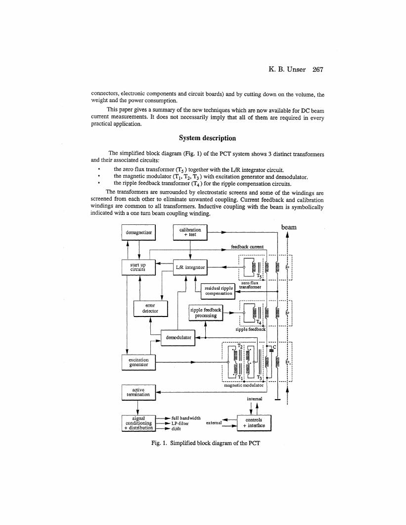
The simplified block diagram (Fig. 1) of the PCT system shows 3 distinct transformersand their associated circuits:
the zero flux transformer (T5) together with the L/R integrator circuit.the magnetic modulator (T1, T2, T3) with excitation generator and demodulator.the ripple feedback transformer (T4) for the ripple compensation circuits.
The transformers are surrounded by electrostatic screens and some of the windings arescreened from each other to eliminate unwanted coupling. Current feedback and calibrationwindings are common to all transformers. Inductive coupling with the beam is symbolicallyindicated with a one turn beam coupling winding.
beam
Fig. 1. Simplified block diagram of the PCT
268 The Parametric Current Transformer
The magnetic cores are demagnetized (depolarized) automatically each time the mainspower is applied. The demagnetizer generates a sinusoidal 50 Hz current (>12 App ) in thefeedback windings and this current decays exponentially with a time constant of a few seconds.Demagnetization of the modulator cores is enhanced by programming the excitation generatorsimultaneously to the highest amplitude before bringing it progressively down to the normalexcitation level.
Demagnetizing is important for the zero flux transformer to define the working pointclose to the center of the B/H loop. This helps to reduce microphony effects, where mechanicalvibrations produce a modulation of the residual (remanent) flux and generate parasitic signals.The microphony effects, without this precaution, are very disturbing and could limit theresolution of the monitor in a practical application (vicinity of vacuum pumps etc.).
The magnetic modulator has a memory of previous exposure to a large current. This isprobably due to a residual remanence effect. Zero readings may change by more than 1 mAafter measuring a current of 1 A, which was, for some reason, not compensated by feedback.This is not only a static offset error, but it is followed by a tendency to drift back during days inthe direction of the original zero state. Demagnetization at low frequency permits erasure of thismemory effect with an residual error of less than ± 2 |jA.
The zero remanence state of the magnetic cores has to be maintained under all operatingconditions. This is the task of the start-up circuits, which apply the feedback current after thedemagnetizing cycle is completed, on condition that there is no error signal from the circuits inthe feedback loop. Error signals are generated if an excessive external current is applied. This isalso transmitted as an error message to the control interface. The error detector has theadditional function to supervise the positive and the negative power supplies. A drop in powercauses an immediate controlled shut-down followed by a demagnetizing cycle when the poweris restored again.
The calibration circuit applies a precision current source to the calibration windings. Thisis useful as a system test and permits the calibration of the entire data acquisition chain (forboth polarities) in a typical application. There is also another function of this circuit: in thecontrol state "test", a known current is added to the current in the feedback windings. Thefeedback current will try to compensate the error caused by this current source. The change inthe zero reading of the PCT can be used to calculate the internal d.c. loop gain of the PCT.
Fast current changes (beam or feedback current) are shorted out with capacitor C, whichis decoupled4 from the modulator with the help of an additional transformer core T3. Thiscapacitor both protects the magnetic modulator from fast transients and attenuates at the sametime high frequency components in the modulator output signal, which are coupled into thefeedback current loop. This coupling, an undesirable effect, is the origin of modulator ripple inthe PCT output signal. A processed modulator output signal is returned back via the ripplefeedback transformer to compensate this unwanted signal at the source (reduction up to 98%).
Earlier instruments4 of this type required a complete 19"- crate with 8 plug-in modules tohouse the electronics. The new design, in spite of many additional circuit functions, requiresonly 2 Eurocards (100 x 160 mm) with 4 micro modules in surface mount technology. The totalpower consumption was reduced by 94% and is now only 3 watts (at zero input current). Theelectronics is placed in a sealed box without ventilation holes (185 x 130 x 70 mm).
The interconnection between the front-end electronic box and the back-end chassis is asingle cable with 3 shielded wire pairs. The first carries the analog signals, the second the powersupply and the third the multiplexed bidirectional controls and the power for the demagnetizer.The back-end chassis contains only the analog signal conditioning and distribution circuits, thecontrol interface and the power supply.
K. B. Unser 269
The Magnetic Beam Sensor
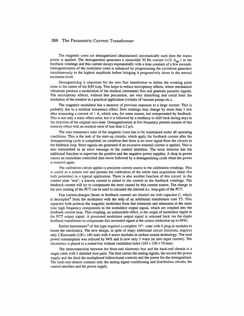
The magnetic beam sensor consists of 5 separate magnetic cores, packed together in thetoroid assembly (Fig. 2). The cores are strip wound toroids having a useful cross-sectionbetween 5 and 25 mm2 depending on the application. Small cross-sections of the cores werepossible thanks to the choice of a high modulation and transition frequency of the system. Thesoft magnetic material is a thin ribbon (5 mm wide, 23 jam thick) of Vitrovac® 6025*, anamorphous magnetic alloy with the composition (CoFe)70(MoSiB)30. This material featureshigher values of permeability and can be used at higher frequencies than conventional(crystalline) nickel/iron alloys.
magnetic shields
Fig. 2. Toroid assembly, simplified cross-sectional view (windings not shown)
The cores for the 2nd-harmonic magnetic modulator (T} and T2) are the most criticalcomponents of the system and the magnetic properties of these cores determine the resolutionand the zero stability of the instrument. Vitrovac® 6025 is now produced in quantity, but thenormal commercial grade has a very large spread of magnetic characteristics. A special qualityis selected by the manufacturer using a detailed set of specifications containing among othersthe following selection criteria:
• low value of magnetostriction ( k s < 0.2 x 10""'• low value of saturation flux density (Bs< 0.5 Tesla)• good surface quality• no brittleness
The selected material is submitted to a series of tests to determine the specific annealingconditions5 for each production batch and the important parameters for the modulatorapplication, i. e. the modulator gain and the magnetic modulator noise. The magnetic noise(Barkhausen noise) depends essentially on the number and the structure of the magneticdomains in the material, which can change with the composition and the annealing treatment ofthe material. Less than 5% of the material received will pass these tests, but the rest can be usedfor all other applications, where these specific characteristics are not relevant.
Certain aspects of the fabrication of the cores have been treated in an earlier publication5
and will not be repeated here. The winding of the modulator cores is a very critical operation.The ribbon has to be continuously controlled with the microscope for mechanical defects (microfractures and surface defects). The correct winding tension has to be carefully maintained. Theinsulation between the layers, a mylar foil of 2 jam thickness, is very delicate and difficult tohandle. It has to be placed with great care to maintain a minimum and equal spacing between
* Vitrovac® 6025 is a trade name of Vacuumschmelze GMBH, D-6450 Hanau, Germany
270 The Parametric Current Transformer
the layers. It is not only necessary to wind all cores with exactly the same number of layers, butalso to position the start and the finish of the ribbon in a well defined position in respect of eachother. The magnetic ribbon is not simply cut at 90° to the longitudinal axis of the tape but at avery narrow angle in order to distribute the discontinuity in the cross-section over a largercircumference. The finished cores are vacuum impregnated and cross field annealed. Thetoroidal excitation winding is applied and all magnetic parameters are measured and recorded.Core pairs are selected by matching the dynamic hysteresis loop to better than 1% (defined bythe factor of attenuation of the modulation frequency in the common output winding).
The magnetic modulator, in the center of the assembly, is a very sensitive magnetometerto external magnetic fields. This is an undesirable feature which can only be attenuated byextensive magnetic shielding. The magnetic shield of the PCT consists of a number ofconcentric magnetic cylinders of different length,.inside and outside the magnetic cores (Fig. 2).The shields which are closest to the cores consist of several layers of Vitrovac 6025 and providethe best shielding factor, but this material is only available with a maximum width of 50 mm.All other shields are Mumetal. Seen in this context, the small cross section of the magneticcores is also an important advantage for efficient magnetic shielding. It helps to bring the innerand the outer shields closer together and reduces the volume of the magnetic beam sensor.
This shielding attenuates the external field by a factor between 50 to 500, depending onthe number of shields in use. This is not enough in many applications. One has also to considerthat high permeability shields are easily saturated by a strong external magnetic field.
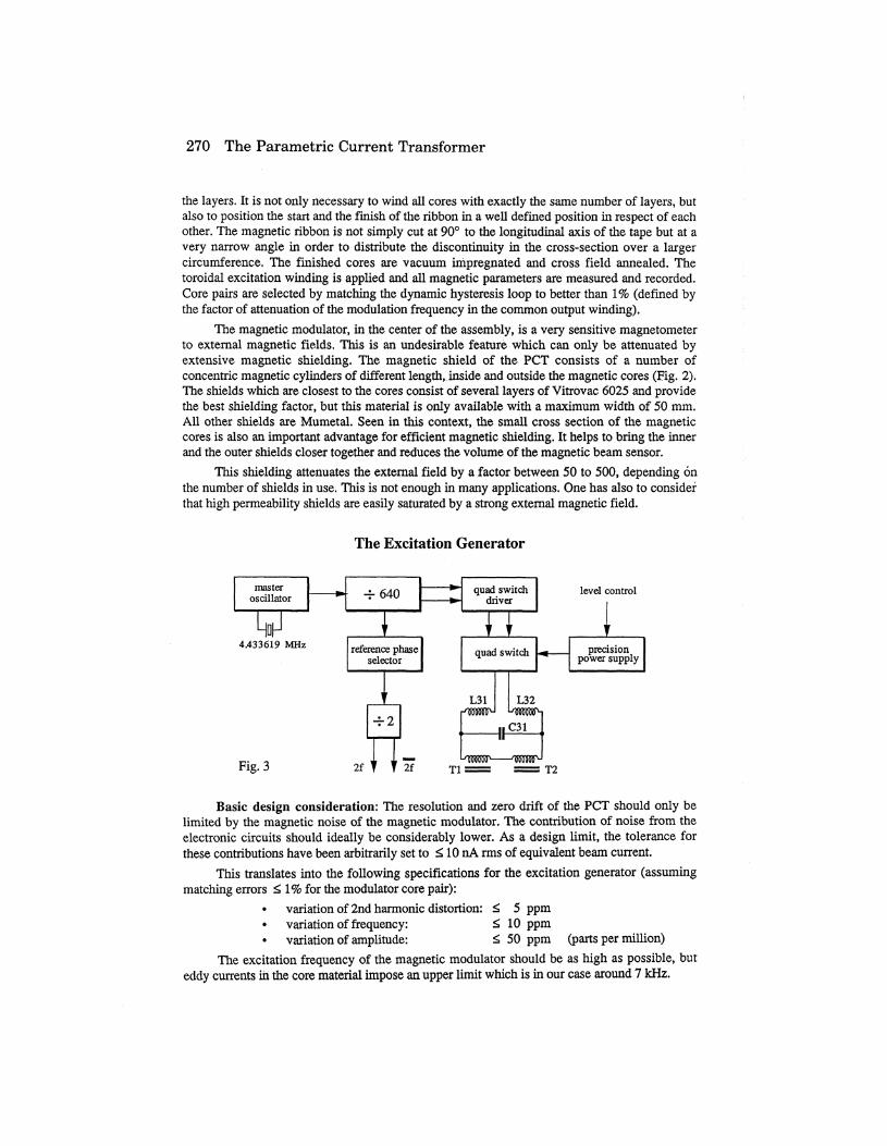
The Excitation Generator
masteroscillator
y4.433619 MHz
~640
i
reference phaseselector
]
-r-2
1 1
—— *~—— *-
quad switchdriver
v }
quadsv
LSI•nmWP
II
vitch
L32LOHRJWC31
II/inciofiotN <TOOnorr\
level control
!^ precision^ power supply
Fig. 3 2f T2
Basic design consideration: The resolution and zero drift of the PCT should only belimited by the magnetic noise of the magnetic modulator. The contribution of noise from theelectronic circuits should ideally be considerably lower. As a design limit, the tolerance forthese contributions have been arbitrarily set to ^ 10 nA rms of equivalent beam current.
This translates into the following specifications for the excitation generator (assumingmatching errors £ 1% for the modulator core pair):
• variation of 2nd harmonic distortion: <> 5 ppm• variation of frequency: £ 10 ppm• variation of amplitude: <> 50 ppm (parts per million)
The excitation frequency of the magnetic modulator should be as high as possible, buteddy currents in the core material impose an upper limit which is in our case around 7 kHz.
K. B. Unser 271
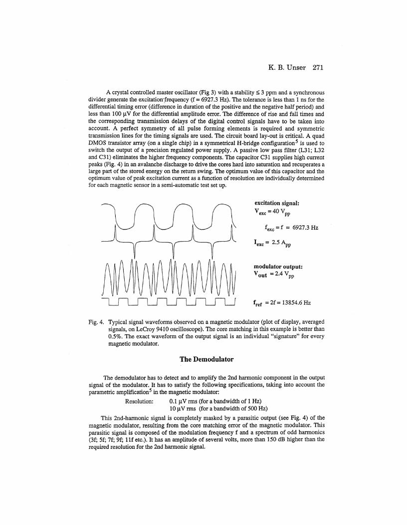
A crystal controlled master oscillator (Fig 3) with a stability < 3 ppm and a synchronousdivider generate the excitation-frequency (f = 6927.3 Hz). The tolerance is less than 1 ns for thedifferential timing error (difference in duration of the positive and the negative half period) andless than 100 jaV for the differential amplitude error. The difference of rise and fall times andthe corresponding transmission delays of the digital control signals have to be taken intoaccount. A perfect symmetry of all pulse forming elements is required and symmetrictransmission lines for the timing signals are used. The circuit board lay-out is critical. A quadDMOS transistor array (on a single chip) in a symmetrical H-bridge configuration5 is used toswitch the output of a precision regulated power supply. A passive low pass filter (L31; L32and C31) eliminates the higher frequency components. The capacitor C31 supplies high currentpeaks (Fig. 4) in an avalanche discharge to drive the cores hard into saturation and recuperates alarge part of the stored energy on the return swing. The optimum value of this capacitor and theoptimum value of peak excitation current as a function of resolution are individually determinedfor each magnetic sensor in a semi-automatic test set up.
excitation signal:V =40 Vyexc . vpp
6927.3 Hz
Iexc=2.5
modulator output:Vo u t=2.4VPP
fref =2f= 13854.6 Hz
Fig. 4. Typical signal waveforms observed on a magnetic modulator (plot of display, averagedsignals, on LeCroy 9410 oscilloscope). The core matching in this example is better than0.5%. The exact waveform of the output signal is an individual "signature" for everymagnetic modulator.
The Demodulator
The demodulator has to detect and to amplify the 2nd harmonic component in the outputsignal of the modulator. It has to satisfy the following specifications, taking into account theparametric amplification5 in the magnetic modulator:
Resolution: 0.1 jaV rms (for a bandwidth of 1 Hz)10|iVrms (for a bandwidth of 500 Hz)
This 2nd-harmonic signal is completely masked by a parasitic output (see Fig. 4) of themagnetic modulator, resulting from the core matching error of the magnetic modulator. Thisparasitic signal is composed of the modulation frequency f and a spectrum of odd harmonics(3f; 5f; 7f; 9f; llf etc.). It has an amplitude of several volts, more than 150 dB higher than therequired resolution for the 2nd harmonic signal.
272 The Parametric Current Transformer
ripplefeedback
magnetic modulatoroutput winding
2f
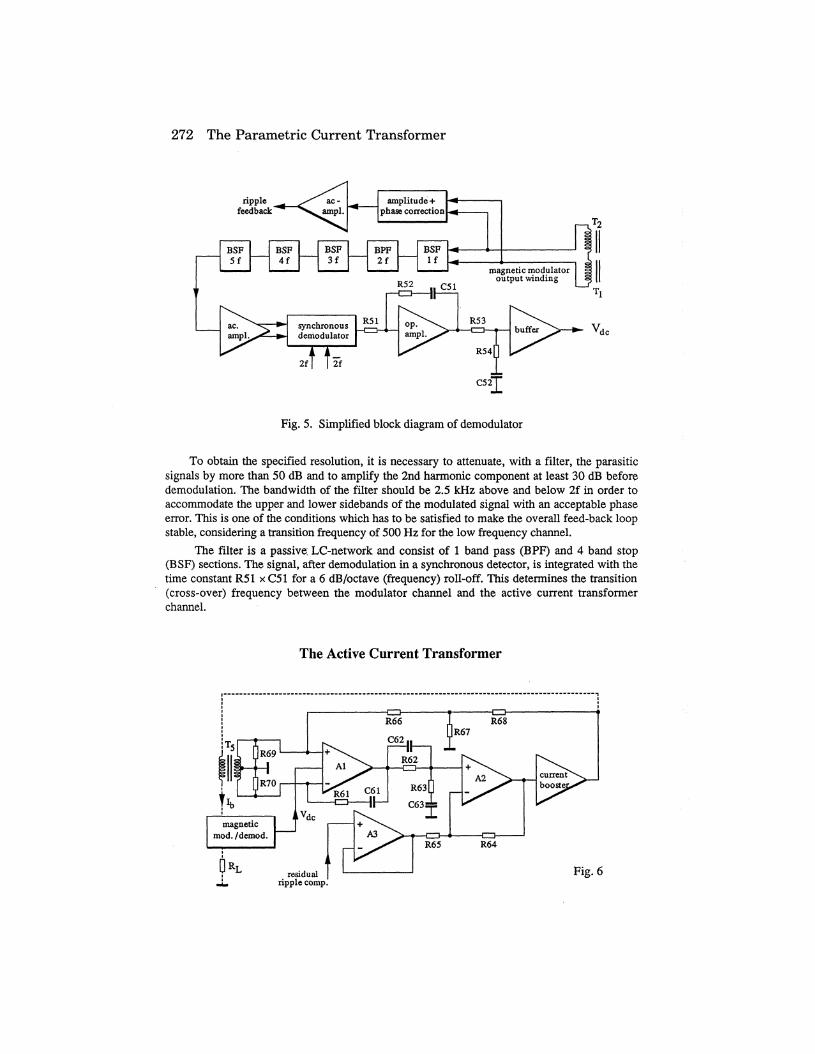
Fig. 5. Simplified block diagram of demodulator
To obtain the specified resolution, it is necessary to attenuate, with a filter, the parasiticsignals by more than 50 dB and to amplify the 2nd harmonic component at least 30 dB beforedemodulation. The bandwidth of the filter should be 2.5 kHz above and below 2f in order toaccommodate the upper and lower sidebands of the modulated signal with an acceptable phaseerror. This is one of the conditions which has to be satisfied to make the overall feed-back loopstable, considering a transition frequency of 500 Hz for the low frequency channel.
The filter is a passive: LC-network and consist of 1 band pass (BPF) and 4 band stop(BSF) sections. The signal, after demodulation in a synchronous detector, is integrated with thetime constant R51 x C51 for a 6 dB/octave (frequency) roll-off. This determines the transition(cross-over) frequency between the modulator channel and the active current transformerchannel.
The Active Current Transformer
ripple comp.Fig. 6
K. B. Unser 273
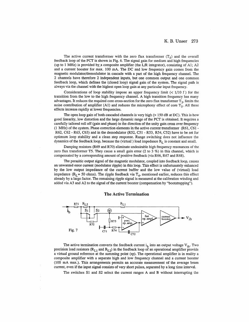
The active current transformer with the zero flux transformer (T5) and the overallfeedback loop of the PCT is shown in Fig. 6. The signal gain for medium and high frequencies(up to 1 MHz) is provided by^a composite amplifier (the L/R integrator), consisting of Al; A2and a current booster for max. 100 mA. The DC and low frequency gain comes from themagnetic modulator/demodulator in cascade with a part of the high frequency channel. The2 channels have therefore 2 independent inputs, but one common output and one commonfeedback loop, which defines the (closed loop) signal gain of the system. The signal path isalways via the channel with the highest open loop gain at any particular input frequency.
Considerations of loop stability impose an upper frequency limit (< 1/10 f ) for thetransition from the low to the high frequency channel. A high transition frequency has manyadvantages. It reduces the required core cross-section for the zero flux transformer T5, limits thenoise contribution of amplifier (Al) and reduces the microphony effect of core T5. All theseeffects increase rapidly at lower frequencies.
The open loop gain of both cascaded channels is very high (> 150 dB at DC). This is howgood linearity, low distortion and the large dynamic range of the PCT is obtained. It requires acarefully tailored roll off (gain and phase) in the direction of the unity gain cross over frequency(1 MHz) of the system. Phase correction elements in the active current transformer (R61, C61 -R62, C62 - R63, C63) and in the demodulator (R52, C51 - R53, R54, C52) have to be set for
optimum loop stability and a clean step response. Range switching does not influence thedynamics of the feedback loop, because the (virtual) load impedance RL is constant and small.
Damping resistors (R69 and R70) eliminate undesirable high frequency resonances of thezero flux transformer T5. They cause a small gain error (2 to 3 %) in this channel, which iscompensated by a corresponding amount of positive feedback (via R66, R67 and R68).
The parasitic output signal of the magnetic modulator, coupled into feedback loop, cause3an unwanted error current (modulator ripple) in this loop. This effect is unfortunately enhancedby the low output impedance of the current buffer and the low value of (virtual) loadimpedance (RL= 50 ohms). The ripple feedback via T4, mentioned earlier, reduces this effectalready by a large factor. The remaining ripple signal is measured at the calibration winding andadded via A3 and A2 to the signal of the current booster (compensation by "bootstrapping").
The Active Termination
R71 RL2
Fig. 7 C71C72
The active termination converts the feedback current ib into an output voltage Vib. Twoprecision load resistors (RL1 and RL2) in the feedback loop of an operational amplifier providea virtual ground reference at the summing point (sp). The operational amplifier is in reality acomposite amplifier with a separate high and low frequency channel and a current booster(100 mA max.). This arrangements permits an accurate measurement of the average beamcurrent, even if the input signal consists of very short pulses, separated by a long time interval.
The switches SI and S2 select the current ranges A and B without interrupting the
274 The Parametric Current Transformer
feedback path and without adding the contact resistance to the load resistor values. The loadresistors RL1 and RL2 are composed of several precision resistors in parallel in order to keep thepower dissipation in each o£them at a low level. Resistor R71 (50 Q) defines the actualimpedance of this active termination in the main feedback loop and keeps it at a constant andlow value to reduce the effects of parasitic capacitance of the different elements in this loop, acondition for loop stability, independent of the selected current range
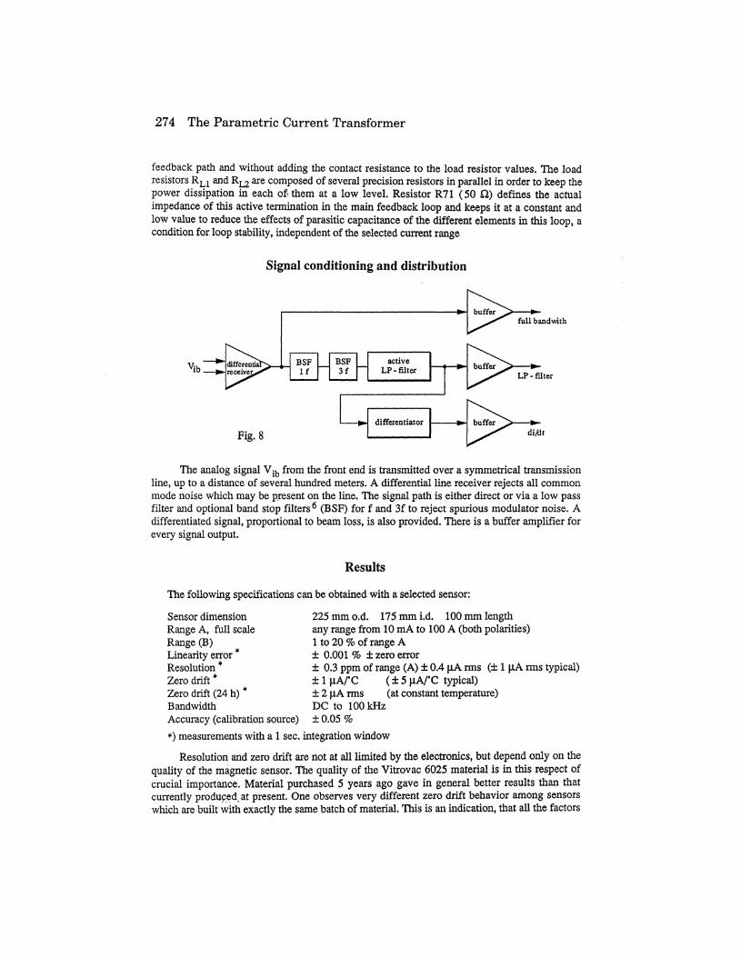
Signal conditioning and distribution
vib.
full bandwith
Fig. 8
LP-filter
di/dt
The analog signal Vib from the front end is transmitted over a symmetrical transmissionline, up to a distance of several hundred meters. A differential line receiver rejects all commonmode noise which may be present on the line. The signal path is either direct or via a low passfilter and optional band stop filters6 (BSF) for f and 3f to reject spurious modulator noise. Adifferentiated signal, proportional to beam loss, is also provided. There is a buffer amplifier forevery signal output.
Results
The following specifications can be obtained with a selected sensor:
Sensor dimensionRange A, full scaleRange (B)Linearity error *Resolution *Zero drift *Zero drift (24 h) *BandwidthAccuracy (calibration source)
225 mm o.d. 175 mm i.d. 100 mm lengthany range from 10 mA to 100 A (both polarities)1 to 20% of range A± 0.001 % ± zero error± 0.3 ppm of range (A) ± 0.4 joA rms (± 1 jaA rms typical)± 1 |4A/°C (± 5 |WC typical)± 2 jaA rms (at constant temperature)DC to 100 kHz±0.05%
*) measurements with a 1 sec. integration windowResolution and zero drift are not at all limited by the electronics, but depend only on the
quality of the magnetic sensor. The quality of the Vitrovac 6025 material is in this respect ofcrucial importance. Material purchased 5 years ago gave in general better results than thatcurrently producedvat present. One observes very different zero drift behavior among sensorswhich are built with exactly the same batch of material. This is an indication, that all the factors
K. B. Unser 275
which influence these characteristics are not as yet clearly identified.The temperature drift is not so much caused by the temperature coefficient of the material
itself than by the uneven mechanical constraints in the two modulator cores. The temperaturedependent zero drift is generally reduced after a period of artificial ageing (temperature cyclingbetween 20°C and 80°C) and the temperature coefficient of the sensor becomes in any casemore reproducible. It is a good idea to incorporate a temperature gauge in the beam sensor, ifthe temperature drift is critical in a particular application.
During long term zero drift test one can sometimes observe in intervals of several hoursor days a fairly sudden change of up to 2 joA. The cause of these phenomena are not known.
Acknowledgments
Many people have made their contributions: C. Bovet and R. Jung gave their support tothe project and many useful discussions are gratefully acknowledged. The computer controlledtest bench for dynamic testing of core samples was designed and built by P. Buksh. Themechanical design of the core winding machine and the different tooling required in the projectwas first the responsibility of A. Maurer and at a later date of G. Burtin.
J. Bergoz, A. Charvet, R. Lubes and P. Pruvost (BERGOZ, F-01170 Crozet. France)designed circuit lay-outs and built the different prototypes. They made experiments with thedifferent construction methods for the magnetic cores and the toroid assembly and performed anincredibly large number of tests to find the optimum annealing procedures. Their practicalexperience in building a large number of PCT's is a valuable help for any future improvements.
G.Herzer, R. Hilzinger, W. Kunz and R. Wengerter (Vacuumschmelze GMBH, D-6450Hanau, Germany) contributed with their knowledge of amorphous magnetic alloys and helpedwith the selection of a suitable quality of Vitrovac material.
References
1. K.B. Unser, "Beam current transformer with DC to 200 MHz range", IEEE Trans. Nucl.Sci., NS-16, June 1969, pp. 934-938.
2. F.C. Williams, S.W. Nobel, "The fundamental limitations of the second-harmonic type ofmagnetic modulator as applied to the amplification of small DC signals", Journal. IEE(London), vol. 97,1950, pp. 445-459.
3. H.C. Appelo, M. Groenenboom, J. Lisser, "The zero flux DC current transformer, a highprecision wide-band device", IEEE Trans. Nucl.. Sci., Vol. N.S.-24, No.3, June 1977,pp. 1810-1811.
4. K.B. Unser, "A toroidal DC beam current transformer with high resolution", IEEE Trans.Nucl. Sci., NS-28, No. 3, June 1981, pp. 2344-2346.
5. K.B. Unser, "Design and preliminary tests of a beam intensity monitor for LEP" Proc.IEEE Particle Accelerator Conference, March 1989, Chicago,Vol. 1, pp. 71-73.
6. R.L. Witkover, "New beam instrumentation in the AGS booster", April 22-24,1991, KEK,Tsukuba, Japan: Proceedings of the Workshop on Advanced Beam Instrumentation,Vol. 1, pp. 50-59.
7. Collaboration contract K 017/LEP (CERN/BERGOZ) Geneva, December 1986.


![Current Transformer[1]](https://img.pdfslide.us/doc/110x75/577ca5521a28abea748b7c14/current-transformer1.jpg)

