Embed Size (px)
Citation preview

,. _/t.Sa- CR4466
/ /
._ (..3
1991LIFE SUPPORT SYSTEMS ANALYSIS
WORKSHOP
Milwaukee, Wisconsin
June 24-27, 1991/
/
WORKSHOP REPORT
March 1, 1992
Peggy L. EvanichThomas M. Crabb
Charles F. Gartrell
Office of Aeronautics and Space Technology
National Aeronautics and Space Administration
Washington, D.C. 20546
(NASA-CR-4466) 1991 NASA LIFE
SUPPORT SYSTEMS ANALYSIS WORKSHOP
Final Reportt I991 (Orbital
Technologies Corp.) 112 p
N93-27100
Unclas
HI154 0162968
https://ntrs.nasa.gov/search.jsp?R=19930017911 2018-08-25T05:35:14+00:00Z

This document is the product of support from many organizations and individuals. The
Orbital Technologies Corporation, under contract to General Research Corporation,
conducted the workshop, developed the proceedings, and prepared the final report.
Sponsored by:
COTR:
Task Monitor:.
Contract Number and Title:
Contractor:.
Subcontractor:.
Program Manager:.
Task Leader:.
National Aeronautics and Space Administration
NASA Headquarters
Code R
Washington, DC 20546
Gregory M. Reck
Peggy L. Evanich
NASW-4470
Space Technology Studies and Support
General Research Corporation
Aerospace Systems Group1900 Gallows Road
Vienna, VA 22182
Orbital Technologies Corporation
402 Gammon Place, Suite 10
Madison, WI 53719
Charles Gartrell
Thomas M. Crabb

CR 4466
1991LIFE SUPPORT SYSTEMS ANALYSIS
WORKSHOP
Milwaukee, Wisconsin
June 24-27, 1991
WORKSHOP REPORT
March 1, 1992
Peggy L. EvanichThomas M. Crabb
Charles F. Gartrell
Office of Aeronautics and Space TechnologyNational Aeronautics and Space Administration
Washington, D.C. 20546
All references to commercial products are comments expressed by the
workshop participants and do not represent a position taken by the U.S.Government.


DISTRIBUTION
Allen S. Bacskay
Code ED62, Bldg T285NASA Marshall Space Flight CenterMSFC, AL 35812
(205) 544-0993
Mark G. Ballin
Code SAS, M/S 239-8NASA Ames Research Center
Moffett Field, CA 94035
(415) 604-5771
Mr. Michael Barrera
Aspen Technology, Inc.251 Vassar Street
Cambridge, MA 02139(617) 497-9010
Dr. W.B. Bedwell
Allied Signal50 E. Algonquin RdDes Plaines, IL 60017-5016
(708) 391-3500
Albert F. Behrend, Jr.
NASA Johnson Space Center2101 NASA Road 1, CODE EC3
Houston, TX 77058(713) 483-9241
Dr. Lawrence BeiglerMCS Division
Argon, IL 40439
Mr. Vincent Bilardo
Code SAS, M/S 239-8NASA Ames Research Center
Moffett Field, CA 94035(415) 604-5752
Dr. Attilio BisioATRO AssociatesBox 1367
Mountainside, NJ(908) 233-1524
07092
Dr. Ray BulaUniversity of Wisconsin1357 University AvenueMadison, WI 53715
(608) 262-5526
Mr. Mel Cobb
Lockheed Missiles & Space CompanyP.O. Box 3504, ORG 6N-12/B580
Sunnyvale, CA 94088-3504(408) 756-6832
Ms. Carolyn CooleyMartin Marietta Civil & Space CommP.O. Box 179, M/S DC8001Denver, CO 80201
(303) 971-9375
Mr. Robert DaLee
McDonnell Douglas Space Systems Co689 Discovery Drive, Mail Code 12C3Huntsville, AL 35806
(205) 922-7320
Ms. Susan Doll
Boeing Aerospace CompanyP.O. Box 240002, M/S JX-23Huntsville, AL 35824-6402(205) 461-3731
Dr. Alan DrysdaleMcDonnell Douglas Space SystemsP.O. Box 21233
Kennedy Space Center, FL 32815(407) 383-3819
Peggy L. EvanichOAST, Code RNASA HeadquartersWashington, DC 20546(202)453-2843
Martha Even
Lockheed/ESC2400 NASA Rd 1, MC-C44Houston, TX 77058
(713) 244-5111
Dr. Michael FehlingTerman Engineering CenterStanford UniversityStanford, CA 94305-4025
(415) 723-0344
Mr. Joseph FerraUJet Propulsion Laboratory4800 Oak Grove Drive, M/C 125-224Pasadena, CA 91109(818) 354-3159

Mr. John Fisher
Code SAR, M/S 239-11NASA Ames Research Center
Moffett Field, CA 94035
(415) 604-4400
Ms. Susan FuhsAIResearch
P.O. Box 2960, M/S T-41Torrance, CA 90509-2960
(213) 512-4600
Dr. Gani B. GanipathiJet Propulsion Laboratory4800 Oak Grove Dr, M/S 125-224
Pasadena, CA 91109
(818) 354-7449
Scott GilleySverdrup Technology, NASA LeRC21000 Brookpark Road, M/S 309-1Cleveland, OH 44135(216) 433-6137
Mr. Ian GoslingAspen Technology, Inc.251Vassar Street
Cambridge, MA 02139(617) 497-9010
Mr. Stephen GustavinoMcDonnell Douglas Space Systems Co5301 Bolsa Avenue, Mail Code 17-B
Huntington Beach, CA 92647(714)896-3311
Mr. Joseph HomaHamilton Standard
One Hamilton Road, M/S 1A-2-W66Windsor Locks, CT 06096
(203) 654-2495
Vibhor Jain
Bionetics CorporationNASA Ames Research Center, MS 239-8Moffett Field, CA 94035(415) 604-1335
Darrell Jan
Jet Propulsion Laboratory4800 Oak Grove Drive, M/C 125-224Pasadena, CA 91109
Mr. Matthew KolodneyLockheed Engineering & Science Co2400 NASA Road 1, M/C C70Houston, TX 77058
(713) 333-7224
Mr. Richard LamparterNASA Ames Research Center
Mail Stop 239-11Moffett Field, CA 94035
(415) 604-1159
Mr. William Likens
Code SAS, M/S 242-4NASA Ames Research Center
Moffett Field, CA 94035
(415) 604-3210
Cheng-Hsiung LinPurdue UniversityLorre/Potter Center, Rm 220
West Lafayette, IN 47907(317) 494-7027
Dr. Chin Lin
NASA Johnson Space Center2101 NASA Roadl
Houston, 'IX 77058(713) 483-9126
Thomas M. MaloneySverdrup Technology, NASA LeRC21000 Brookpark Road, M/S 309.1Cleveland, OH 44135
(216) 433-6137
Dr. David OUis
Chemical Engineering DepartmentNorth Carolina State UniversityRaleigh, NC 27695(919) 737-2329
Dr. Firooz Rasouli7449 N. Natchez Avenue
Niles, IL 60648-3892(312) 647-9000
Mr. Barney Roberts
NASA Johnson Space Center2101 NASA Road1, Code IE2Houston, TX 77058(713) 283-5460
Dr. Naresh RohatgiNASA Jet Propulsion Laboratory4800 Oak Grove Drive, M/S 125-224Pasadena, CA 91109
(818) 354-3073
Dr. Willy SadehDepartment of Civil EngineeringColorado State UniversityFort Collins, CO 80523
(303) 491-2001

Nelson Schlater
Bionetics CorporationNASA Ames Research Center, MS 239-8Moffett Field, CA 94035
(415) 604-1335
Dr. Richard SeagraveIowa State UniversitySweeney Hall, Room 238Ames, IA 50011
(515) 294-0518
Dr. P.IC Seshan
NASA Jet Propulsion Laboratory4800 Oak Grove Drive, M/S 125-224Pasadena, CA 91109(818)354-7215
Dr. Charles Simonds
Lockheed Missiles and Space1150 Gemini Ave, M/C A23Houston, 'IX 77058(713) 282-6203
Dr. Kamalesh K. Sirkar
Stevens Institute of TechnologyCastle Point
Hoboken, NJ 07030
(201) 420-5432
Dr. Robert Sirko
McDonnell Douglas Space Systems Co5301 Bolsa Avenue, Mail Code 13-2Huntington Beach, CA 92647(714) 896-3817
Mr. Thomas Slavin
Boeing Aerospace & Electronics DivisionP.O. Box 3999, M/S 84-15Seattle, WA 98124(206) 773-1471
Mr. Paul SpurlockS&A Automated Systems, Inc.123 NW 13th Street, 13th Floor, Ste 222Boca Raton, FL 33432
(407) 750-8786
Dr. Ted Tibbitts
University of WisconsinRoom 327, HorticultureMadison, WI 53706(608) 262-1816
Mr. William Trail
Aspen Technology, Inc.251 Vassar Street
Cambridge, MA 02139(617) 497-9010
Raymond B. TruschHamilton Standard
One Hamilton Road
Windsor Locks, CT 06096
(203) 654-2495
Dr. George TsaoPurdue UniversityPotter Building-1295West Lafayette, IN 47907(317) 494-7022
Dr. Tyler VolkNew York University26 Stuyvesant StreetNew York, NY 10003
(212) 998-8995
Raymond M. WheelerNASA Kennedy Space CenterCode MD-RES
Kennedy Space Center, FL 32899(407) 853-5142
Dr. Lionel R. Whitmer
Boeing Missiles and Space DivisionP.O. Box 240002, M/S JR-34Huntsville, AL 35824-6402
(205) 461-5854
Mr. Versie L. Wilson
Boeing Missiles and Space DivisionP.O. Box 240002, M/S JR-34Huntsville, AL 35824-6402
(205) 461-5822
Dr. Bruce WrightBoeing Missiles and Space Division499 Boeing Blvd, M/S JR-34P.O. Box 240002
Huntsville, AL 35824-6402(205) 461-5822

THIS PAGE INTENTIONALLY LEFT BLANK

t_sA _ _pp_ sym=s A_ W_op
TABLE OF CONTENTS
eaa
1.0 WORKSHOP OBJECTIVES AND SUMMARY ................... 1 ""
2.0 SUMMARY OF CONCLUSIONS AND RECOMMENDATIONS ...... 5
3.0 STEADY STATE AND DYNAMICS SYSTEMS ANALYSIS
WORKING GROUP RESULTS 9- _e_eeeeeooooeeoooee oeoeoooe eooe •
4.0 MODEL VALIDATION AND SCALE-UP ASSESSMENT
WORKING GROUP RESULTS .............................. 15
5.0p-
EVALUATION CRITERIA WORKING GROUP RESULTS ......... 23 --
6.0 BIOLOGICAL SYSTEMS ANALYSIS WORKING GROUP RESULTS . 27 - _'
7.0 SYSTEMS INTEGRATION WORKING GROUP RESULTS ......... 33 - /
APPENDICES ................................................ 41
A. DETAILED AGENDA ..................................... 43
B. LIST OF WORKSHOP PARTICIPANTS ....................... 51
C. WORKING GROUP PRESENTATIONS ....................... 57
o
2.
3.
4.
5.
LIST OF FIGURES
NASA Life Support Technology Programs Use of Systems Analysis ..... 2
Life Support Systems Analysis Workshop Time Line ............... 2
System Dependency Matrix ................................. 34
Propulsion Interfaces With Power and Life Support ............... 35
Power Interfaces with Life Support and Propulsion ............... 35
i wo_op emcmfiap

THIS PAGE INTENTIONALLY LEFT BLANK
ii

uasx tit= s_tma s_:s _ waeatml,
1.0 WORKSHOP OBJEC'FIVF__ AND SUMMARY
L1 Wor_hop Overview
The NASA Life Support Systems Analysb Workshop was sponsored by NASA
Headquarters' Office of Aeronautics and Space Technology (OAST) to foster
communication among NASA, industrial, and academic specialists, and to integrate their
inputs and disseminate information to them. Life support technologies will require a broad
base of systems modeling experience. Adequate validation of models and appropriate
capability to scale-up prototype processes will be necessary to model and develop longer-
duration life support systems that may ultimately be self-sufficient. The specific goals of this
workshop were to report on the status of systems analysis capabilities, to integrate the
chemical processing industry technologies, and to integrate recommendations for future
technology developments related to systems analysis for life support systems.
NASA is coordinating the life support systems analysis development through several
technology programs, shown in Figure 1. These efforts support the development of input
data, modeling algorithms, and validation of key life support technologies that will be
integrated into an operational system. The overall objective of systems analysis within the
Life Support Technology Program of OAST is to identify, guide the development of, and
verify designs which will increase the performance of the life support systems on component,
subsystem, and system levels for future missions beyond the currently planned Space Station.
The Workshop, held over three days (25-27 June 1991) in Milwaukee, Wisconsin, included
technical presentations, discussions, and interactive planning, with time allocated for
discussion of both technology status and time-phased technology development
recommendations. Key personnel from NASA, industry, and academia, currently involved
with life support technology developments, delivered inputs and presentations on the status
and priorities of current and future technologies. Figure 2 provides an overview of the
workshop organization, while Appendix A contains the detailed agenda.
1.2 Workshop Sessions and Presentations
The workshop contained six technical sessions, four working group sessions, two real-time
software demonstration sessions, and a luncheon keynote address. Comments from an
initially planned NASA review panel, for reasons of time conservation, were integrated into
the working group presentations and into the last technical presentation session.
f_
PRE_,EOING PAGE BLANK NOT FILI_'IED
¢

MASAUfc S_,a_ _J,m _u,J_ _mi_
or)m
Or)>-_.1
Z
IEILlI--
>-
0
o
oo _.o____o _,,-_<
g_ g'6 g'- o_.-EE_o o c_
,. m IE _0- I_ _,.0 ,- m m
-_o® _ 0 _,-
i

TUESDAY
WEDNESDAY
THURSDAY
8:00 em 9:00 me 10:00 u 11:00 _ 12:00 noon I 1:00 pm 2:01_ I_ 3:00I
NASA Life Support Systems UorkGp Lunch Presen- AnaLogouslntroJ AnaLysis Capabitities/Toots Eick tstion: LSS Systems AnaLysis Break
Off Strategies Approaches/TooLs
4:00 pe 5:00 I_
Work ing Group
I_et ing #I
Life _rt Applications Lunch EvaLuation Criteria
Software Demonstration of Systems Anatysis (on your own)i _ Future AnaLysisPresentations
Software Oesonstration (One-on-One Discussions)
Uorking Group Presentations ILSS Project S'.mJ
Worki_ Group
Heeting N2
FIGURE 2. Life Support Systems Analysis Workshop Time-Line
6:00 pm
Reetpt ion
!
Presentations within the six technical sessions highlighted NASA goals for systems analysis
for life support, status of current NASA model developments, insight into systems analysis
from the chemical processing industry, applications and examples of the NASA systems
analysis modeling, future analysis approaches and evaluation mechanisms, and an overview
of the NASA life support technology program. Specific sessions included:
@ Introduction and Overview. A welcome and an overview, by Peggy Evanich, of the
NASA life support technology program goals and their relationship to the systems
analysis and the goals of the workshop. Future requirements for life support
technologies and applications induce the need for additional development and
analysis relating to figures of design and operational merit.
@ Overview of NASA Life Support Systems Analysis CapabUities/Tools. Five presentations
highlighting the NASA model developments using ASPEN PLUS, CASE/A, G189A,
and spreadsheet tools. Modeling levels ranged from process simulation to the
integration of component and subsystems performance models into a total system.
Analogous Systems Analysis Approaches�Tools. Insights from three chemical industry
systems-analysis experts into concerns of scale-up, validation of actual systems
implementation vs. expected or planned performance, and optimization techniques
to minimize iteration requirements.
Life Support Application of Systems Analysis. Four presentations of systems analysis
applications relating to Space Station Freedom, Extra-Vehicular Activity (EVA) suit
subsystems, Lunar Outpost, and Mars Exploration.
Future Analysis Approaches and Evaluation Criteria. Six presentations addressing
detailed systems integration analysis, the role of Artificial Intelligence (AI) in future
systems analysis, integration of biological systems analysis, decision analysis
techniques, and evaluation mechanisms/tools.
3 w_ rrm_l_ao

l_m._ ute .s_ spmm AmSm woam_
Overview of NASA's Life Support TechnologF Program. A NASA/ARC review of thePhysical-Chemical Regenerative Life Support Project, including managementstructure, approach to developments, and near-term planned activities. NASA/JSCprovided an overview of the Lunar Base Life Support Testbed activity.
Appendix A lists full presentation rifles and their respective presenters. Copies ofpresentations were compiled in a workbook and distributed to participants at the workshop.
Barney Roberts, Manager of the Planet Surface System Office at NASA/JSC, presented anoverview of the Lunar and Mars mission scenarios, including insights into the role of life
support systems within planetary surface bases.
1.3 Workin_ Groups
Five working groups were formed to apply the specialized talents and experiences ofworkshop attendees to discussions of these specific systems analysis development areas:
Working Group
Steady State and Dynamics Systems Analysis
Modeling Validation and Scale-up
Evaluation Criteria
Biological Systems Analysis
Systems Integration
Working Group Chairman
Dr. P.IC Seshan, JPL
Dr. Chin Lin, NASAJJSC
Mr. Allen Bacskay, NASA/MSFC
Dr. Raymond Wheeler, NASA/KSC
Dr. Naresh Rohatgi, JPLMr. William Likens, NASA/ARC
Each working group articulated key development issues relating to systems analysis, anassessment of the current state-of-the-art, and potential recommendations for pursuit of
those issues. Working group efforts and milestones were divided across the workshop's three
days. The first day was devoted to defining the key issues and characterizing the state-of-
the-art or the status of current developments. The second day continued with development
of recommendations for each of the key issues identified. Working group leaders presented
reports on the third day. These reports appear in Appendix C, and are summarized inSections 3 through 7.
wm_lop _ 4

2.0 SUMMARY OF WORKSHOP RESULTSAND RECOMMENDATIONS
The NASA Life Support Systems Analysis Workshop provided an excellent opportunity for
NASA, industry (aerospace and chemical processing), and universities to collaborate on
modeling and analysis techniques and tools for advanced life support. The contributions of
key personnel in many disciplines yielded valuable results, which are summarized in this
section. Common needs identified throughout the working groups included:
• Investigation of the effects of micro/partial gravity affects to life support process and
system simulation and analysis.
• NASA guidance in development of standards for developing simulation modules,
prototype and testbed testing procedures, and data collection and communication.
• Additional workshops and/or agency-wide advisory groups to support a united
technology analysis and development program for life support.
• Integration of the physical-chemical and biological systems.
• Significant technology development and basic research in waste treatment and
resource recovery.
• Additional analysis of system controls and other operational factors in early design
phases.
2.1 Steady State and Dynamics Systems Analysis Working Group Summary
The Steady State and Dynamics Systems Analysis Working Group addressed current and
future needs for systems analysis approaches, tools, and techniques. Key issues identified
and recommended as priorities for future activities included"
Develop additional generic-component simulation modules and guidelines that induce
a commonality among any life support component model for use with many systems
analysis tools.
Determine systems parameters that are needed for rigorous dynamics simulation, and
generate rigorous dynamics simulation, especially in the design and analysis of control
systems.
5 wort,i,_ l'tt,,z_n,_

ttAsA Lia: SeR== S_te== ._=t_m W_
Obtain experimental and design data from technology developers, and implement
requirements in future design, development, and fabrication procurement to supply
data appropriate to systems analyses.
Identify and document the design parameters, modeling algorythms and driving
mechanisms (physical, chemical, transport and thermodynamic) of life support
systems and technologies affected by micro/partial gravity. A workshop on this
subject would reveal significant effects from existing modeling and experimental data,
and identify new experiments where necessary.
• Develop property data for trace contaminant control modeling.
Model Validatioa and Scale-up Assessment Workin= Group Summary
The Model Validation and Scale-up Assessment Working Group addressed: 1) the effects
and relationships of systems analysis with testbed prototypes of various levels, and 2)
integrated systems analysis data and results to projected real-life systems applications. Key
issues/recommendations included:
Develop guidelines for prototype and testbed design, to account for appropriate
sizing based on the relative size of the life support system application, and to include
testing and data collection that directly relates to validation and scale-up within
systems analysis models.
Develop data collection capabilities to enhance interfaces between the systems
analysis modelers and the testbed developers and evaluators, such that iterations and
free transfers of data are possible and appropriate between modeling results and
hardware testing results.
Conduct more prototype/testbed activities to verify scale-up correlations both on a
component level and on a systems level, to identify economies of scale that may not
always be obvious or may not always be accurate.
Investigate the effects of micro/partial gravity in the governing equations of process
simulations, perform thorough study of gravity-sensitive processes, and conduct teststo characterize those sensitivities.
Develop a standardized validation test series guideline through establishment of
rigorous experiment design techniques and an advisory panel to include NASA,
industry and academic members.
w, arlaa=n,_ 6

2.3 Evaluation Criteria Working Group Smnmar3/
The Evaluation Criteria Working Group addressed the parameters, methods, and tools used
to evaluate the life support system technologies and designs, from component-level hardware
through system level designs, as well as from the conceptual design phase through flight
operations phases. Key issues/recommendations addressed by the working group included:
Develop consistent evaluation criteria that depend on the phase of the development
cycle and the level of component/systems analysis, and methods to combine
appropriate evaluation criteria into a single measure of performance.
Investigate strategies and techniques for identifying and implementing life support
system evaluations, including various systems analysis, decision analysis, life cycle cost,
and/or dimensional analysis techniques.
Expand the evaluation factors and modeling parameters of life support systems and
components to include operational and other reliability/maintainability factors, even
in early phases of development and analysis.
2.4 Biologi_'cal Systems Analysis Working Group Summary
The Biological Systems Analysis Working Group addressed basic issues of data requirements,
tools, and techniques required for systems analysis of life support technologies that integrate
biological component(s). Key biological systems analysis issues/recommendations developed
by the working group included:
Develop consistent approaches for biological life support systems testing through
experimental set-up guidelines, data reporting guidelines, and a central focus for
biological systems data.
Begin augmenting the currently available data on primary production and waste
treatment through additional controlled testing of specific biological components and
systems.
Q Augment long-term and large-scale biological systems testing through many time
constants of the biological system.
Develop data on human behavioral effects relating to the presence or absence of
biological systems, through literature searches and human behavioral evaluationrelated to isolated environments.
7 w, ata_ rnaxeatap

• Initiate detailed testing and analysis to determine the driving factors in various
biological systems (e.g., primary production, waste treatment) affected bymicro/partial gravity.
2.5 Systems Inteeration Workine Group Summa_
The Systems Integration and Analysis Working Group addressed the future potential andrelated requirements for analyzing and assessing the potential of integrating the life supportsystems with other systems in future mission architectures such as the Initial Lunar Outpost,an evolved lunar base, a Mars base operation, and manned transit vehicles.
Two levels of integration exist. A top-level systems integration analysis can utilize estimatedmass and resource interfaces among the life support system and other systems (power,
thermal, propulsion, etc.) to predict the level of synergism among integrated systems. Asecond level of integration, much more detailed, could then be conducted on systems thathave potential for performance payoffs because of synergistic integration, involving detailedsimulation and systems modeling of each system/component and the interfaces with other
systems/components.
Overall recommendations by the worldng group included:
Sponsor a meeting of key technical staff involved in life support, power, propulsion,thermal and other systems that may potentially be integrated with the life support
system.
Analyze possible high pay-off system interactions involving the life support system,
including effects of integration on risk, maintainability, and reliability. Althoughintegrated systems may initially demonstrate beneficial relationships that reduceresupply through synergistic uses of common resources, they may be less beneficial
operationally, when reliability and maintainability of additional and integrated systemsare considered.
Investigate potential use of common materials and components from other systemsand potential application of life support materials and components to other systems,including standard interfaces and connectors.
• Assess effects of systems integration to the evolution and growth of the life supportsystem.
woma_ rm_d_p 8
3.0 STEADY STATE AND DYNAMICS
SYSTEMS ANALYSIS WORKING GROUp
The Steady State and Dynamics Systems Analysis Working Group addressed current and
future needs of systems analysis approaches, tools, and techniques. The working group was
chaired by Dr. P. K. Seshan of the Jet Propulsion Laboratory; participants are listed at theend of this section.
Key issuesincluded:
• Additional generic component simulation modules are needed.
Rigorous dynamic simulation should be pursued and evolved with systems and
technology developments to mainly support control system development.
Experimental and design data from technology developers would significantly improve
modeling accuracy.
• Development of a property data for trace contaminant control modeling is required.
• Effects of micro/partial gravity on modeling must yet be integrated to current models.
Other issues discussed but not fully developed by the working group included:
Dynamic simulation modeling can form a basis for the operational control system
development.
Various levels of modeling, from process simulation to subsystem/system level
modeling, are required to accurately estimate performance.
3.1 Generic Component Simulation Modules
ASPEN Plus and CASE/A have many modules, but are not always generic and usable by
various software tools. However, some modules needed for life support systems analysis are
not built-in or readily available. Many of the life support process units and unit operations
are not generic but could be expressed in terms of one or more built-in generic modules of
software packages. ASPEN Plus provides for custom building of new modules. Thus,
ASPEN is one tool that could be used to generate additional generic modules.
9 wottaa_ _

RECOMMENDATIONS - Generic Component Simulation Modules:
• Additional generic modules are needed, including:
Electrochemical reactor
Ion exchange
Membrane SeparatorPlant
Metabolic humans
Kitchen
Dishwasher
Clothes washer
Clothes drier
Toilet
Shower
Metabolic animal
Bioreactors (various kinds)
A more rigorous Vapor Compression Distillation (VCD) module is needed forCASE/A.
Module development by users should follow specific format and assumption
guidelines such that they may be interfaced across several systems analysis tools. The
module developers should therefore agree on module structure/interface. Standardi-
zation of generic modules would allow sharing of modules, and would minimize
duplication of effort among many systems analysis tools.
3.2 Rigorous Dynamic Simulation in Life Sup eort Systems Analysis
CASE/A, G189A, SPEEDUP and SIMTOOL have various aspects of steady state and
dynamic simulation capabilities. ASPEN Plus can simulate transient performance of
individual blocks by using RBATCH and custom code modules capable of executing
sophisticated integration algorithms.
CASE/A and G189A do not contain the standard tools for control system analysis (i.e.,
analysis of performance dynamics). MATRIX, System Build, and MA_ are control
system design/analysis software packages; however, they are not chemical process simulation
packages. Only one commercial chemical process simulator, SPEEDUP by Prosys
Technology, can simulate dynamics within a block and across an entire flow sheet using
sophisticated integration methods. However, SPEEDUP is not very user-fiiendly.
Rigorous dynamic simulations are needed for system response and controllability studies, for
control system design and testing, but not for systems analysis. Rigorous dynamic simulations
are not needed during conceptual system studies and technology development. They have
little relevance to system parameters such as weight, volume, power demand, etc.
wem_p _ 10

n_t.sAtires_n _ mmbw wea_op
RECOMMENDATIONS - Rigorous Dynamic Simulation in Life Support Systems Analysis:
Quasi-steady state simulation capability in ASPEN Plus should be developed to
monitor changes in storage tanks.
Rigorous dynamic simulations must be part of the design review process, especially
for transient thermal response of process equipment including highly exo/endothermicchemical reactors.
• Dynamic simulations should be used at the conceptual stage for early concept
definition of control strategies.
Standard guidelines should be developed to identify the level of dynamics simulation
detail required for modeling of components systems of various natural response
frequencies.
3.3 Experimental Data from Technoloev Developers to Support Systems Analysis
Component and subsystem packaging may have an important effect on the ability to scale
up weight and volume. Data pertaining to the optimal performance of a component alone
will not be adequate, since system-wide optimum performance may necessitate suboptimal
component performance.
RECOMMENDATIONS - Experimental Data from Technology Developers to Support
Systems Analysis:
Gather the following data for different sizes of process equipment, and throughout
(and slightly beyond) the nominal operating envelopes:
Performance data on failure modes, including failure of a redundant
component.
Weight, volume, and other applicable data of individual process units,
instruments, wiring, plumbing, fittings, support structures, insulation/lagging
and any other packaging materials/structures.
Basic chemical reaction data such as kinetic rate constants and equilibrium
constants for reactions, as well as hardware dependent data such as flow rates,
power demand, etc.
Operating conditions such as temperature, pressure, feed concentrations, etc.,
as well as performance parameters such as percent conversion/separation.
11 we,t_ _

O All technology development proposals must contain a section on scale-up, detailingapproaches and deliverables to enable scale-up correlations to be developed. All
technology development proposals must be reviewed by system analysis personnelwith experience in process simulation and equipment scale-up. Theirrecommendations and data as desen'bed above should be made part of the contractdeliverables.
3,4 Micro/Partial Gravity_ Effects on Thermodynamic. Transnort and Kinetic Pronerties
Several contractor and NASA reports are available on the subject of microgravity effects oncomponents and subsystems. A 1990 Lockheed Engineering and Science Company reportincludes many of the governing equations. Gravity affects transport processes;
thermodynamic properties are not expected or known to be affected by the magnitude of
gravity. Equih'brium properties of finely divided particles, bubbles and droplets, however,could exhibit gravity dependence. Typical Earth-gravity phenomena are often overcome in
microgravity environments due to homogenous mixings of multiple phases and surface energyeffects.
RECOMMENDATIONS - Micro/Partial Gravity Effects:
• Generate a micro/partial gravity effects database relative to life support systems.
Sponsor a NASA workshop of experts in properties measurements to identifycurrently available information on gravity effects on life support systems related
processes, and define potential experiments to be conducted in micro/partial gravity
environments to generate missing data for the above database.
Use aircraft micro/partial gravity flights to simulate the various gravitational
environments in which life support systems must operate. Development of an
automated flight profile controller would help to optimize the desired gravity
environment, maximize duration in low gravity simulations, and increasereproduc]qaility of acceleration profile. Current designs are available for such an
aircraft instrumentation system.
• Plan, establish, and fund a program of chemical and physical propertiesmeasurements on Space Station Freedom.
3.5 Property ,Data for Trace Contaminant Control Modelin2
ASPEN Plus contains a large database, can calculate properties based on molecular
structure, and can track trace chemicals in the model by setting extremely tight toleranceson convergence. These trace contaminants may greatly affect the performance of life
w__ 12

_A._, tare .*_p_t _ ,*,m_m woamtop
support components. For example, trace contaminants such as methane and carbon
monoxide may also affect the life cycle and size of the Bosch unit, and must be accuratelyaccommodated.
Some trace contaminants may not be known until prototyping and testing. In these cases,
additional modeling must be pursued to determine the source of the contamination, any
problems which may affect performance, and solutions to alleviate the contamination.
RECOMMENDATIONS - Trace Contaminant Property Data:
Obtain kinetic data for trace contaminants not found in the ASPEN Plus database,
through literature search or experiments. Since possible contaminants are too
numerous to model and track in any single simulation, the preferred modeling
approach would organize the known contaminants into ten or fewer classes and select
a representative compound for each class for modeling trace contaminant processes
in life support systems.
Iterate trace contamination modeling with component and system prototype testing
to analyze and verify unexpected contamination problems.
3.6 CONTRIBUTORS
P.K. Seshan (Chair)Michael Barrera
Scott GilleyMark Ballin
Tom Crabb
John Fisher
Matt Kolodney
Joe Ferrall
V. L Wilson
R.C. DaLee
13 wea=_ rmaxd_

m_._ L_ Sq_m S_zB AJ_ Wett=_
THIS PAGE INTENTIONALLY LEFT BLANK
_ 14

_VLSALi__n _am _ Wc=t,_m_
4.0 MODEL VALIDATION AND SCAI.E-UPASSESSMENT WORKING GROUP
The Model Validation and Scale-up Assessment Working Group addressed the effects and
relationships of systems analysis with testbed prototypes of various levels, and integration of
those data to projected real-life systems applications. The working group defined validation
as "a mechanism to integrate real data produced from hardware experiments into the
modeling analysis to improve user confidence in the results of the models." Dr. Chin Lin
of NASA JSC chaired the working group. The participants are listed at the end of thissection.
Key issues highlighted by the working group report include:
• Prototype and testbed requirements are needed to standardize and maintain good
results for use in systems analysis.
Data collection requirements could be standardized and made available to enhance
integration of data in modeling and scale-up assessment.
Scale-up data is required from prototype/testbed for use in model validations andscale-up estimation.
• Effects of micro/partial gravity need to be addressed to identify driving mechanisms
which will affect modeling, analysis, and scale-up assessment.
• Validation test series must be a continuous process from benchtop tests through flightoperations.
4.1 Prototype and Testbed Requirements
To date, existing life support technologies have been prototyped and developed only for
modeling and analysis validation on a component or subsystem level. In addition, most
hardware data now available for advanced life support technologies are at bench-top or pre-
prototype levels. Development of standard requirements or guidelines for prototyping and
testbed development would more consistently generate useful and valid data to compare and
validate with systems analysis models. Such guidelines should include proper prototyping
and testing design and operation so that the accumulated data supports development of
accurate scale-up correlations (see Section 4.3).
Two major supporting issues were identified. The first supporting issue was the ability to
determine whether test data were developed with prototype/testbed sizes within a justifiable
15
_; _-"FR_E'DiNG PAGE BLANK NOr FILMED

range of the modeling application(s). By experience, researchers have found that the validrange of test data extrapolation is very small, centering around the size of the prototype.Scale-up from these limited data is often insufficient and inaccurate because of unknowninfluences which create different correlations for systems at different size levels.
The second supporting issue concerned the need for validation and scale-up to be considered
at both component and integrated system levels, each of these representing very differentapproaches. The validation and scale-up of components depends largely on the parametersand assumptions directly related to the process simulation. However, integrated systemsvalidation and scale-up are more commonly affected by the interactions of several
components/subsystems rather than by a domination of a single process.
Another current problem with existing data used in validation and scale-up is that the dataavailable for various components of a life support system come from prototypes of a wide
range of sizes. Also, inadequate parameter sensing and data collection within the prototypeor testbed hardware can leave many holes within the database.
At this time, math/computer models are not used regularly to support scale-up of life
support systems. This type of analysis and mathematical representation of scale-up has onlyrecently been implemented. When using such models, only scale-up correlations validated
through appropriately sized prototypes and testbeds should be used to determine economiesof scale, and to define parameters whose correlations are significantly affected by changesin scale.
This represents, at a basic level, a protocol of modeling and testing that requires iterationof modeling/analysis and experimental prototypes/testbed developments. The data collectedduring prototype/testbed evaluations and the data used and derived through modeling mustbe similar if not identical. Also, the assumptions and operational environment of the
analyses and testing must be similar for comparison.
RECOMMENDATIONS - Prototype and Testbed Requirements:
The working group recommended the pursuit of two modes of validation and scale-upprototyping and testbed activities. The first recommendation is to build and test prototypes
at incremental levels up to at least one-fourth of the flight hardware capacity. Thus,
different missions and different life support systems may require different levels of
prototyping and different stages within the prototype series to develop proper validation and
proper scale-up correlations. These levels of prototyping at the systems level will impact thecomponent-level prototype sizing and testing.
Secondly, the working group recommended prototyping and testing a series of testbeds atboth the component level and the integrated systems level. Component-level prototypetesting and characterization, ff conducted with procedures and in sizes relevant to the
ultimate integrated system, can lead to integration of the component-level prototypes into
wod_q, r.,mx_ 16
_,sA t_ seppm s_u:_ _ worbUop
an integrated system testbed to determine the inter-component relationships and related
scale-up correlations. This is already being planned at the JSC, and the working group
recommended following up this activity with a very coordinated series of prototypes and
testbeds across the entire life support system within this testbed activity.
4.2. Data Collection Requirements
Hardware and test data must be efficiently collected, reported and organized to support
proper use within the modeling and analysis, and to enhance proper comparisons among
prototypes and testbeds at differing technologies and sizes.
A specialized life support systems technology database has been started at the ARC;
however, it is unclear whether a single, centralized database could ever be totally complete
and include all necessary information for modeling all of the processes, components,
subsystems, and integrated systems. A preferred approach would be a centralized pointer
system, which merely directs inquiries to the correct source of valid data. For this option,
the data would be maintained throughout the nation (and the world) at the originating
locations, where updates may be recorded in a more timely fashion. Also, substantially more
data may become available from additional sources of information (for example, data
collected by Boeing and Lockheed). One problem cited is the reluctance of many
organizations, private or public, to permit access to such data for competitive or proprietary
reasons. A necessity of either approach is a protocol of data which includes output results,
assumptions used, and specific configuration information of the process or hardware.
System-level test data, and some component-level test data, are rather limited in range and
number of parameters tested. Basic understanding and determination of fundamental
driving mechanisms within processes to support validation of systems performance modeling
are, in many cases, incomplete. Such incompleteness leads to a lack of parameter detail to
track and provide, as a data set, information that can be used in validation and scale-up
efforts. Also, the lack of knowledge of fundamental driving mechanisms affects the validity
and accuracy of scale-up correlations developed from such data.
Chemical industries do not invest any funds into a production process without knowing these
driving mechanisms, without knowing what is key to the scale-up correlations, and without
knowing what is key to the overall component subsystem and system performanc_ Developing
tests and prototypes to isolate _l parametets is required to identify some of these driving
mechanisms. Modeling and analysis can help identify these driving mecimnisn_ but they must
then be proven and validated in a testbed situationL
17 wa_op emoeed_

_ ut= sam=_ s_t=_ AaabmWeaatzp
RECOMMENDATIONS - Dam Collection Requirements:
Continue expansion and enhancement of a centralized database or database network.Incorporate or at least identify the source of relevant test data on variouslife supporthardware.
Open better channels of information exchange between the private sector and NASA
so that existing test data on currently used hardware can be made more consistentlyavailable.
Make a commitment to acquire necessary data from model validation and
development of scale-up correlations. This includes establishing a generalizedprotocol for defining the test assumptions and set-up requirements such that the testdata is compatible with the systems being modeled. Thus the modeling and analysis
must provide input into test requirements. This input could be a list of data and
parameters to track, identification of potential key driving mechanisms to watch for,pre-test predictions of output data from the test model, and other environmental/operational requirements under which the testbed would operate. In addition, theremust be sufficient resources in the hardware testing program for sensor placement,
monitoring, and storing of in-depth measurements of specific parameters that areisolated from other variables, and to conduct many of these experiments and testsover wide ranges of operation. Specific protocols exist in which to supportexperimentation development to minimize the number of experiments based on the
number of dependent and independent variables that need to be tracked.
4.3. Scale-up of prototypesfrestbeds
Developing scale-up correlations from prototypes and testbeds raises questions of whichanalysis techniques should be used, whether the data used and available is adequate for the
scale-up correlations, and which mechanisms should be used to coordinate the modeling
analysis with the hardware scale-up correlations. To date, test data are not usually collectedduring the prototype or testbed to support various scale-up assessments. Data is lacking toaccurately verify the parameters represented in the data sets of a specific process subsystems
and to adequately predict performance of large crew life support systems. For example,most currently available test data exists only for crew sizes smaller than four. This isconsidered extremely inadequate to accurately scale-up a component or a subsystem to
capacities larger than 16-person crews.
To the present, scale-up correlations have been typically developed in parallel with othermodeling and analysis features, but not as an integral part of the modeling and analysis. Theworking group recommended procedures to integrate the scale-up correlations directly into
the modeling and analysis, initial development, and later verification.
Wom_op_ 18

g_,sA L_ S_ S_m ,_.m_ W_ahop
Dimension and similitude analysis techniques need to be used across the board and in a
more standardized fashion with respect to both component- and system-level scale-up
procedures. Scale-up correlations may be quite different for components and integrated
systems. Compiling the scale-up correlations of many integrated components may not
adequately reveal the scale-up correlations that will be found in the integrated system.
Validation of scale-up correlations of the system-level hardware is also definitely required.
RECOMMENDATIONS - Scale-up of Prototypes/Testbeds:
Develop and verify through testing scale-up correlations along two major influences
of performance estimation: level of integration and overall size magnitude. Scale-up
correlation development and verification may begin at the process or component
level, but must also be developed for integrated subsystems and systems. Because
scale-up correlations are rarely linear and influencing mechanisms change as the size
of the component/system increases, this scale-up correlation must be developed and
verified for various sizes appropriate to the ultimate application.
The scale-up correlation must take advantage of systems analysis, process modeling,
and prototype testing to support more accurate development of scale-up correlations.
Broader use and iterative integration of hardware scale-up correlations into the
modeling and analysis should be pursued.
Dimension analysis and similitude analysis must be pursued on a more common and
across-the-board basis at both the component and systems levels.
4.4. Effects of Micro/Partial Gravity
In developing model and systems analyses, using data from component- and subsystems-
level tests in a 1-g environment may not, and probably will not, assure accurate performance
estimation in a micro/partial gravity environment. Key driving mechanisms must be explored
within the process simulation and in the component interactions at the systems level to
assure that the validation of 1-g testbeds is accurate for micro/partial gravity applications.
Gravity is not an explicit parameter in most life support systems modeling analyses; however,
it may play a crucial role in some of the microprocesses that occur within the life support
systems. Independent studies have identified certain processes such as gas/liquid interfaces
in life support systems that are very sensitive to levels of gravity. Other processes within life
support systems that have been shown to be affected include buoyancy, electrolytic double
generation, steam condensation and certain biological plant growth effects.
To date, some components and sub-systems-have been tested in different orientations on
Earth to drive out what may be some of the effects on component or system performance
19 wom_¢ rmomaap

roam Lie t_tt a_zm A=_ W_*a_
from various gravity environments. Other tests and flight experiments conducted on aircraftand the Space Shuttle,as well as testscurrentlyplanned for Space StationFreedom are
ascertaining gravity effects in life support component performance. However, to date, no
rigorous comparative testing of sister component prototypes has been made from Earth-based to micro-g-based to lunar-based to Mars-based gravity levels.
RECOMMENDATIONS - Micro/PartialGravityEffects:
Re-examine the governing equations used in current systems analyses, processsimulations and other models to verify that the gravity effects within the assumptions
are justifiably negligible or adequately applied.
Perform a thorough study to identify g-sensitive processes and develop testrequirements for new and emerging life support technologies so that gravity effects
can be appropriately estimated and validated.
For g-sensitive processes, conduct ground tests and parallel or sister flight
experiments to measure directly the effects of gravity. These may be conducted onaircraft simulations, and potentially on Space Station Freedom should a centrifuge
be developed to provide partial gravity. They may also be tested on aircraft flight
experiments, the Space Shuttle, and station racks for miero-g effects.
Study current life support systems in the shuttle and planned life support systems inSpace Station Freedom to determine the gravity effects on already-developedhardware.
4.5. Validation Test Series
Validation is a living process, starting from the benchtop test to the full flight test; it is not
a single-event determination. Typical timeframes for development of life support systemsare on the order of a decade or more. Typical cycles in the chemical industry are on the
order of a year. Thus, many more tests and validation activities could occur to assureadequate performance of the life support systems throughout the development cycle. The
build-up of test data will be vital to the determination of systems performance through
systems analysis modeling. No well-defined test strategy exists to accumulate relevant data
in adequate quantity or quality to support validation of current systems modeling and
analysis.
RECOMMENDATIONS - Validation:
Use rigorous experiment design techniques to maximize return of necessary testing.This includes the Design of Experiment(DOE) technique to minimize the number
of experiment runs to isolate a certain number of variables and parameters.
w__ 20

Form an agency-wide advisory group including representatives of industry and
academia to formulate a consistent and comprehensive testing strategy. The testing
strategy must stress consistency within the operational procedures, parameters
monitored and measured, and reporting and storage of data. The initial set-up and
operating environment, inputs to the test, and any other assumptions must be
maintained with the output data.
Maintain iterative coordination between the modeling and systems analysis such that
the results of modeling can feed into testbeds and the data coming out of testbeds
can improve the accuracy of systems analysis models.
4.8 CONTRIBUTORS
Chin Lin (Chair)Vibhor Jain
Chin Lin
Kamalash Sirkar
W.B. BedweU
Darin Kohles
David OUis
Mel Cobb
Bill Likens
Firooz Rasouli
21 woa._t, rm_dins,

_msA t,i_ s_tt _ _ wett=_
THIS PAGE INTENTIONALLY LEFT BLANK
wol.tat_ _ 22

KAsAt,i_s=a=m ay=== m=a_ w=t=_
5.0 EVALUATION CRITERIA WORKING GROUP
The Evaluation Criteria Working Group addressed the parameters, methods, and tools used
to evaluate the life support system technologies and designs from component-level hardware
through mission architecture designs, as well as from the conceptual design phase through
flight operations phases. The working group was chaired by Allen Bacskay of NASA/MSFC.
Participants are listed at the end of this section.
Key issues addressed by the working group included:
Consistency of evaluation criteria is required to enable synergy around NASA
developments and missions.
• Approaches exist to develop and implement viable ECLSS evaluations.
• Elaboration of ECLSS drivers.
5.1 Consistency of Evaluation Criteria
Systems evaluation criteria are constantly driven by the diversity of design and development
goals within NASA component research initiatives (e.g., bioregenerative emphasis of OSSA
vs. physical-chemical emphasis of OAST) and the disparity in scale of projected mission
requirements (e.g., achieving low earth orbit vs. habitating the moon vs. exploring Mars).
However, with the recent need for synergistic cooperation, overall evaluation criteria should
be consistent with a few high-priority goals common throughout NASA and among all
missions. From these high-level criteria, supporting evaluation criteria may be developed.
RECOMMENDATIONS - Evaluation Criteria Consistency:
Develop a set of criteria that is mutually acceptable to all groups involved and readily
applicable to their needs. This may reduce subjectivity of decision-making in mixed
research programs through consistent and logical evaluations. This includes
evaluation criteria that is technically based as well as criteria imposed from the
political structure. Honesty in development of the evaluation criteria will enhance
the probability that the end-item development will meet original expectations.
Sponsor a working group or workshop with representatives from all ECLSS
constituent disciplines to provide a balanced and coherent view of significant issues.
Distribute background information and currently used evaluation criteria (as a
conceptual springboard) to attendees, with the expectation of generating productive
discussions and producing a mutually acceptable evaluation method that is
independent of mission type and duration.
23 Woa=aopr_==n=_
._P.,,RE_EDING PAGE ELANK NOT FILMED

Establish varying levels of evaluation criteria based on the phase of the program
(conceptual design vs. flight prototypes) and level of analysis (component level vs.systems level). In each of the varied levels, flow-down of design requirements andassociated evaluation criteria must occur downward (i.e., from the more advanced
development stage to the less advanced development stage, and from the system level
to the component level).
5.2 Cand|d_te Strategi'es for ECLSS Evaluations
The working group discussed three existing approaches that involve development and useof systems evaluation criteria. Study of the following approaches may provide useful insights
to life support systems analyses:
• The approach demonstrated by a Lockheed systems analysis manual, which begins
with a clearly identified objective. (Reference: Holtzman, Samuel, 1988, IntelligentDecision Systems, Addison-Wesley, Reading, MA, 288 pp.)
• Decision analysis that does not require a perfectly articulated objective as a starting
point, and that can accommodate changing emphases over time. (Reference: Space
Systems Division Systems Engineering Manual, Code 66, June 1985, Lockheed Missile
and Space Co., a unit of Lockheed Corp., Sunnyvale, CA, 301 pp.)
• Life cycle cost, which can be used to evaluate any objective requirement or resource,
offers a common unit of comparison, and purportedly increases in accuracy as the
project advances.
RECOMMENDATIONS - Evaluation Strategies:
• Develop single, most important criterion at each of various levels of hardware
(component through system) and at each of various phases of development (concept
through operations).
• Use standardized analysis approach (decision analysis, life cycle cost analysis, etc.) to
establish the evaluation criteria to represent the ultimate goals of life support systems
developments.
5.3 Elaboration of ECLSS Design Drivers
Mass, volume, and power are generally acknowledged to be the most critical engineeringfactors in designing extraterrestrial missions. But, as the scope and duration of projected
missions increases, other factors become more important and may overwhelm the effects of
mass, volume and power. For example, a design may save 50 pounds of mass, but decreases
w,_a_ol, l_lm_ 24

reliability such that the total mass requirement over the lifetime of the life support system
exceeds the initial savings several times over.
RECOMMENDATION - ECLSS Drivers:
Assess the impact of operational and reliability/maintainability factors. Examples of such
factors include: crew preference, resupply needs, functionality, recoverability, maturity, and
safety margins, as well as reliability, EVA time, IVA time, readiness, verifiability,
palietizability, heat flux, residence time, acidity, total organic carbon, toxicity, organolepticity,
gravity field sensitivity, absorptivity, corrosion rate, and resistance to corrosion.
5.4 Other Issues Raised But Not Specifically Discussed
Several issues, raised but not analyzed in depth, should be reopened at the next workshop.These include:
Determine an accurate costing of research and development, and operations that
include typically hidden government infrastructure costs.
Definitions of "system," "subsystem," "component," and "process" should be clarified
and standardized (and sub- and super-systems).
Relationship between the functionality and cost of the life support systems should bedefined as a function of closure.
Procedures for applying weighting factors in life support system criteria are critical
to overall systems evaluation and sensitivity/trade-off assessment.
The effects of "requirement creep" during the development phase can drastically
affect the evaluation criteria and determination of an optimal approach.
Iterative modeling studies and testbed assessments should be based on a consistentset of criteria.
• Regeneration vs. resupply benefits must be assessed based on evaluation criteria.
• Evaluation criteria must account for the availability of in-situ resources.
Applications of deterministic vs. probabilistic assessments should be determined and
recommended as guidelines.
25 w_

N_.SA titc .r,_n S_ _ W_
• Commonalities amongbioregenerative and physical-chemical approaches mayprovide
a good evolutionary growth and should be identified.
Breakpoints and large paybacks in technology development need additionalassessment and identification.
"Palatability" criteria such as astronaut's dietary preference needs to be integrated
into other design and performance criteria.
• Innovative life support system evaluation criteria should be investigated.
• How-downs of requirements and configurations changes to the evaluation criteria are
of major importance to designers and scientists during development.
Judgments based on non-technical or non-economical basis should be avoided or atleast documented in the evaluation criteria.
5.8 CONTRIBUTORS
Allen Bacskay (Chair)Martha Evert
Nelson Schlater
Lionel Whitmer
Susan Doll
Joe Homa
Chuck Simonds
Tom Woodzick
Alan Drysdale
Willy Sadeh
Paul Spurlock

6.0 BIOLOGICAL SYSTEMS ANALYSIS
The Biological Systems Analysis Working Group addressed basic issues of data requirements,
tools, and techniques required for systems analysis of life support systems containing
biological subsystems/component(s). Dr. Ray Wheeler from NASA Kennedy Space Center
chaired the working group; participants are listed at the end of Section 6.0.
Key biological systems analysis issues developed by the working group included:
• Consistent approaches are needed for biological life support systems testing.
• Additional data is required on primary production and waste treatment.
• Long-term data on biological system operation will improve systems analysis results.
Data on human behavior relating to biological systems will increase the overall
performance of the crew and should be reflected in relevant evaluation criteria.
Effects of micro/partial gravity on biological systems are important factors for process
assessment and analysis.
Data requirements for food processing and development of a data repository for biologicalsystem characteristics were identified but not discussed in detail.
6.1 Consistent Approaches for Biological Life Support Systems Testin_
A consistent or standardized approach for biological life support system testing does not
currently exist. Several experimental procedures are being followed with varying operational
conditions. Many test data sets are incomplete, and others do not identify the operational
setups and conditions under which the tests were conducted.
RECOMMENDATIONS - Biological Testing Approaches:
• Define the critical inputs and outputs and controlling factors.
Consider the multi-variable response surface approaches rather than merely definingoptimum levels based on two variables.
• Employ statistical tools to handle the variability.
Develop a generic repository for biological systems data for use in a standard
modeling approach.
27 wea, a_p _

Nm_,ut_ _ _pum_ mm,pi w_m_p
6.2 Avai.!abili_ of Data for Primary Production and Waste Treatment
Data on biological systems are often scarce or nonexistent. Much of the existing data is
available only from small laboratory scale bench-top prototypes. The available information
to predict the performance and characteristics of an entire life support system using a
biological processing component may not be appropriate or accurate for primary production
and waste treatment. A categorized status of data for various biological systems follows.
PRIMARY PRODUCTION
- Food / Biomass Production
- Water Transpired (Distilled)
- Carbon Dioxide Removed
Oxygen
Contaminants (trace)
Environmental
response/performance
Good, extensive data
Extensive data
Some direct measurements
(e.g., KSC Biomass Production Chamber)Extensive data from biomass calculations
Produced few direct measurements (e.g.,
KSC BPC)Can be estimated from biomass
production data
Very little data
Extensive data
Not all conducive to
response surface analysis
multi-variable
• WASTE TREATMENT AND RESOURCE RECOVERY SYSTEMS
Cellulose Conversion Limited data, bench-top level
Aerobic Treatment
Systems
Little data
Commercial technology data available e.g.,
sewage treatment
Anaerobic Treatment
Systems
Less data than aerobic treatment systems
Commercial technology data available e.g.,
sewage treatment
Biomass Leaching toRecover Minerals
Limited data
woma=)p _ 28

NASA Life: SupportSystemsAnalysLsWorkshop
Aquaculture/Animal
Systems for Conversion ofInedible Biomass
Limited data
• MASS REQUIREMENTS ESTIMATES
Productivity of crops Limited integrated system data. Area
needs, lamp/ballast needs, water
requirements, and waste treatment
systems will dictate the mass
requirements.
Plant Culture System Little data reported, but should beobtainable
Good data available on area/volume
requirements
Crop performance allows estimation of
mass requirements
Biological Waste
Treatment/Resource
Recovery
Little data available
Some data on water volume/mass of
aquaculture systems
ENERGY REQUIREMENTS ESTIMATES
Good data on irradiance levels
- Plant Lighting Power requirements may be calculated
Heating, Ventilation, and
Air Conditioning (HVAC)
Little data from direct measurements
Good estimates should be obtainable
Water Pumping Few direct measurements
Estimates easily obtainable
Waste Treatment Systems Little data
RECOMMENDATIONS - Primary Production and Waste Treatment Data:
• Establish the mass, power, and volume requirements for operating biological primary
production and waste treatment systems.
29 Workshop Proceedings

Initiate testing of various biological waste treatment and resource recovery systems
to generate data useful in modeling system operation.
Address the lack of data on animal systems for use in waste management, and initiate
survey of poss_le animal (e.g., other than microbiological) options for waste
conversion. Possible candidates include fish, poultry, and insects to convert inedible
plant biomass and provide a protein supplement for humans. Assess the advantages
and disadvantages to each.
Identify power, mass and volume requirements for plant cultural activities, harvesting,
and food processing.
6.3 Long-Term Data on Bioloeical Systems Operations
The data and experience of biological systems is largely based on short duration, single
generation tests. Also, the testing environment is rarely closed to itself and does not
represent a biological life support system/component that will rely on less than 100%
effective performance of resource recovery. Thus, long-term and large-scale effects over
many biological time constants are rarely input into the systems analysis model. Because of
this, an integrated biological life support system cannot currently be modeled accurately.
RECOMMENDATIONS - Long-Term Operations Data:
• Initiate/continue large-scale studies to assess scale-up problems for biological systems.
• Initiate long-term studies to assess performance of biological systems over several
biological time constants.
• Initiate tests of biological systems that are not open-looped but require resource
recovery without "fresh," unperturbed resource inputs.
6.4 Human Behavior Data
A lack of research has left insufficient data relating to human behavior and the presence or
absence of plants. No research studies could be referenced to help determine a positive or
negative effect of plant life to human behavior and any related improvement of human
performance.
woem_p _ 30
m_s,_,L_ tMZgort_ _ W_m,,3t,
RECOMMENDATIONS - Human Behavior Data:
Conduct extensive literature search for human response/behavior studies assessing the
benefit (or problems) of having plants nearby and/or benefits from engaging inhorticultural activities in an isolated environment.
Initiate studies of human response and behavior in isolated living/working areas with
and without plants (e.g., psychological benefits studies).
Factor results from literature and/or surveys into modeling approaches assessing the
advantages of different life support systems.
6.5 Micro/Partial Gravi_ Effects on B|olo_cal Systems
Very little data is available on partial gravity effects on primary production of biological
systems, and no such data is available for biological waste treatment systems. Correlations
of systems performance in micro/partial gravity environments cannot be predicted without
some valid data points. The basic driving mechanisms must be determined at the various
gravity levels to support adequate analyses and modeling.
RECOMMENDATIONS - Micro/Partial Gravity Effects:
Initiate a testing program to characterize the operation and productivity of biological
systems (especially plant production and waste treatment systems) under micro/partial
gravity through aircraft, suborbital, Space Shuttle, and future Space Station Freedom
flight experiments.
Support basic research to estimate the effects of micro/partial gravity on biological
systems, from the understanding of the basic driving mechanisms and
physics/chemistry.
6.6 Other Biological Systems Analysis Conclusions{Recommendations
Expensive biological systems software exists, but very little information exists to be entered
into it. Workshop participants agreed that consistency in the approaches for testing and
datagathering was critical. Additionally, there should be a "fine tuning" of experimentation
to obtain data about the optimum primary production/processing performance, and decrease
the data and assumption variability. The compilation of a "Journal of Life Support" was also
suggested.
31 woe,_p _

ggsA t_ sappm s_mm _u=_ w, at=_
6.7 CONTRIBUTORS
Ray Wheeler (Chair)
Alan DrysdaleStephen Gustavino
Dick Seagrave
George T. Tsao
Ray Bula
Gani GanipathiJanis Moths
Robert Sirko
Tyler Volk
Carolyn CooleyIan GoslingNelson Schlater
Ted Tfobitts
Bruce Wright
w,=tat_ _ 32

7.0 SYSTEMS INTEGRATION WORKING GROUP
The Systems Integration and Analysis Working Group addressed the future potential and
related requirements for analyzing and assessing the posslq_ility of integrating the life support
systems with other systems in future mission architectures such as the Initial Lunar Outpost,
an evolved lunar base, and a Mars base operation, as well as in the transit vehicles involved
in those mission architectures. The working group was co-chaired by Dr. Naresh Rohatgi
of the Jet Propulsion Laboratory and William Likens of NASA Ames Research Center.
Participants are listed at the end of this section.
Integration exists at two levels. A simplified systems integration analysis can take advantage
of estimated mass and resource transfers among the life support system and other systems
such as power, thermal, propulsion, etc., to predict the level of synergism among integrated
systems. A more-detailed level of integration analysis could then be conducted on specific
large pay-off integrations through detailed simulation and systems modeling of each systemand its interfaces.
This working group addressed the more-detailed analysis approach and concentrated on
identifying the physical interfaces between the life support system and other technologies and
systems. Other considerations that should be included in systems integration analysis but
were not addressed in detail within this working group because of time limitations include:
standards, materials, connectors and interfaces, component and design commonalities,
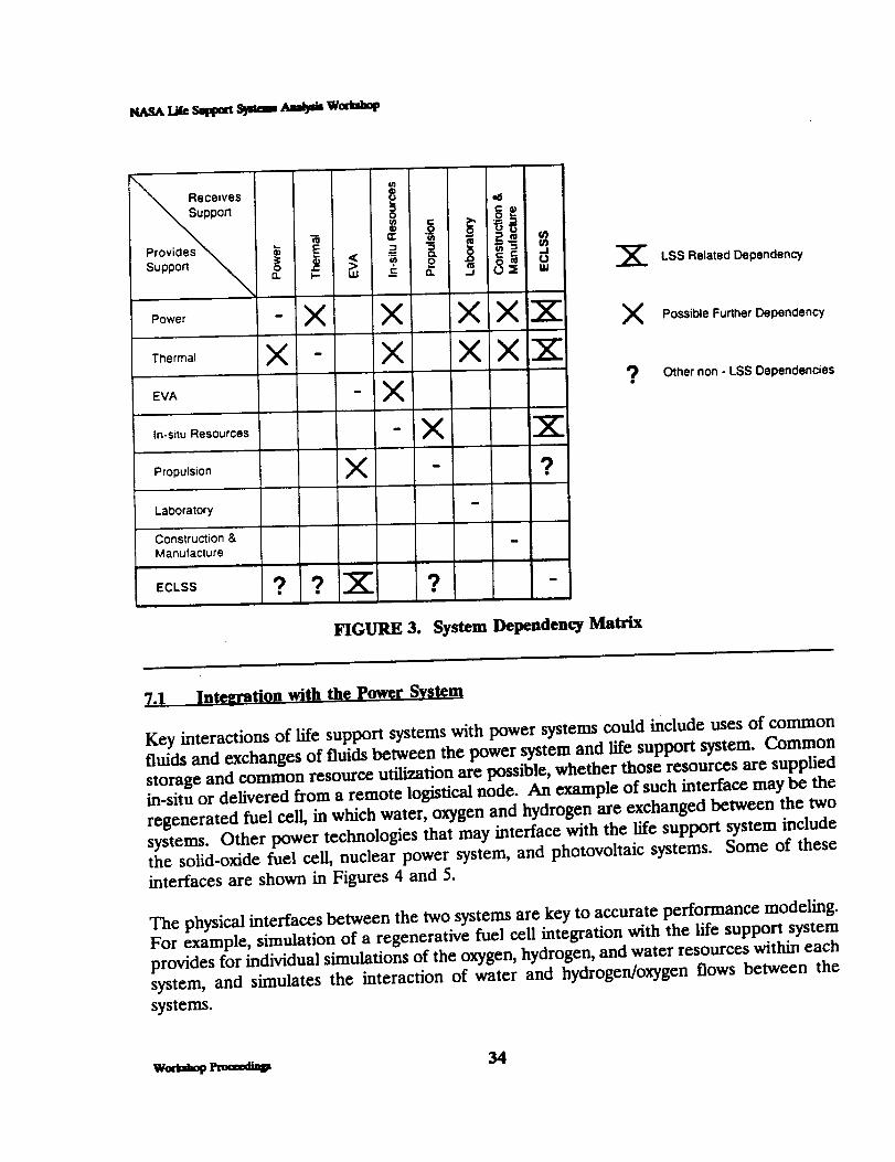
reliability, and risk dependencies. A first-cut dependency identified by the working group
(shown in Figure 3) involved interaction of the life support system with the power system,
thermal system, in-situ resource systems, propulsion systems, and laboratory systems. These
dependencies apply not only to surface-based architectures, but also to surface vehicles and
EVA systems where life support systems exist. Each of these system integrations will be
discussed independently in the subsections below.
The integration of in-situ resources would decrease the necessary resupply for a less-than-
closed life support system. In addition, common storage vessels and facilities and common
ground handling technologies may be very advantageous. Some of the in-situ resource
developments may also be successfully integrated with power and propulsion in thermal
systems.
33 w_lml_ _
NASAU_ Seppm Spu_ ,_abt weem_
\ Receives
Provides _ _ _ =
Support "_ ¢
o _ XO.. I-,- LU --c
Power
Thermal
EVA
In-situ Resources
Propulsion
LaDoratory
Construction &Manufacture
ECLSS ? ?
X
FIGURE 3.
v. ¢J
XX' XXX'
?
D
?
System Dependency Matrix
LSS Related Dependency
Possible Further Dependency
Other non - LSS Dependencies
7.1 In teeration with the power System
Key interactions of life support systems with power systems could include uses of common
fluids and exchanges of fluids between the power system and life support system. Common
storage and common resource utilization are poss_le, whether those resources are suppliedin-situ or delivered from a remote logistical node. An example of such interface may be the
regenerated fuel cell, in which water, oxygen and hydrogen are exchanged between the two
systems. Other power technologies that may interface with the life support system include
the solid-oxide fuel cell, nuclear power system, and photovoltaic systems. Some of these
interfaces are shown in Figures 4 and 5.
The physical interfaces between the two systems are key to accurate performance modeling.
For example, simulation of a regenerative fuel cell integration with the life support system
provides for individual simulations of the oxygen, hydrogen, and water resources within each
system, and simulates the interaction of water and hydrogen/oxygen flows between the
systems.
w,,lal,_ rl==dt_ 34

[ Lss _--->.[ po_er i
H20, LH=, LO= ,_ _ electrical
I Lunar Cargo Lander Lunar Sortie Vehicle
l
FIGURE 4. Propulsion Interfaces With Power and Life Support
CRYO
LOX ]'ANK
Materials interface cRvo STORAGE
Io Lile Support & Propulsion
Power interface
to Life Support & Propulsion
COMI"I_ESSORS (?)
GO2
TANK
ITEGRATED RAD
COMPRESSED GAS STOnAGE
Materials interface
to Lile Support & Propulsion
Thermal interface
to Life Support & Propulsion
FIGURE 5. Power Interfaces with Life Support and Propulsion
35 wom_op

_m._ t_ sq_n _ _ w_awp
7_ Integration with Thermal System
Common interfaces between the thermal system and life support system may include sharingof water and storage systems for either water or air. The life support system could interact
with the thermal system to eliminate and add heat depending on the changing impacts ofequipment heat dissipation and external thermal considerations.
Modeling of the physical resource interfaces between the two systems is key to the prediction
of overall benefits of the integration synergism. Performance modeling of the integrated
system and the life support system must aecomodate the transfer perameters of a common
fluid. Also, heat-balancing synergism may occur from various subsystems within the life
support systems and from subsystems external to the life support system.
7.3 Integration with Propulsion Systems
The integration of the propulsion system(s) with both the power system and the life support
system looks very promising, but depends on the specific propulsion systems beingintegrated. Some of these interactions were shown in Figures 4 and 5.
Hydrogen/oxygen propulsion systems have a good potential for resource sharing in commonstorage fluids such as water, hydrogen, and oxygen. This may also integrate well with aregenerative fuel-cell power system.
Hydrazine propulsion also exhibits some potential integration with the life support system,since hydrazine will decompose into nitrogen and hydrogen. The nitrogen can be used as
make-up gas in a life support system, and the hydrogen can be used as a fuel source within
the life support system, particularly in carbon dioxide reduction technologies.
Electric propulsion could share some of the same fluids used by the life support system, suchas hydrogen, methane and nitrogen. Such electric propulsion systems include nuclear-
thermal propulsion ion thrusters, arcjets, the magnetodynamic ion thrusters. Other, more
advanced propulsion systems, such as fusion rockets, may be able to use common fluids suchas hydrogen.
Other considerations of integration with the propulsion systems must consider the availabilityand use of in-situ resources.
7.4. Inte2ration With In-situ Resources Utilization (ISRU)
Several commonalities among the In-Situ Resource utilization (ISRU) developments at
different nodes within the lunar and Mars infrastructure can be combined and integrated
with the life support system to enhance its performance. The infrastructure required toprocess local resources is, in most cases, not trivial and is typically more massive and power
WeA_ol,_ 36

consumptive than simply resupplying the materials/resources. The operational costs of the
ISRU; however, can induce a cost payback after only a few years of operation. The payback
is enhanced ff synergistic use of the locally produced resources is shared among several
systems such as the life support system.
Oxygen, hydrogen, nitrogen, and several other volatile elements are available from lunar
regolith processing. Carbon dioxide may be retrieved from the Mars atmosphere for use in
plant growth chambers, or for direct conversion to oxygen for the life support system, and/or
to produce methane (when combined with hydrogen) for power production or propulsion.
On Mars, ice/water may be retrieved from the planetary surface, below the planetary surfaceor from the nearby Mars moons.
Other elements, such as aluminum or magnesium from lunar regolith or Mars soils, may be
used with oxygen from the lunar regolith as fuels for a waste-processing system/subsystem
within the life support system.
Lunar regolith or Mars soil may be configured in either a solid or granular bed formation
for filtration or absorption.
7.5. Integration With Laboratory Systems
The capability of the life support system to handle human by-product and food by-product
wastes is extremely important. This capability could be integrated with laboratory systems
such that waste from the laboratory could also be handled in a single waste-handling unit
subsystem. Although these waste streams may be segregated from the life support system
itself, waste-handling technologies and development costs may be shared among certaincomponents.
7.6. Integration With Construction and Manufacturing
The basic integration of the life support system with associated construction and
manufacturing activities is characterized by the reuse of life support system wastes. For
example, ash from a supercritical water oxidation facility might be used in a shielding for alunar base or other vehicle.
Waste plastics from food or other packaging may be remanufactured into new packaging or
decomposed into carbon and hydrogen for use elsewhere in the life support system, and/or
could be used as radiation shielding. Other waste materials may be remanufactured into
foils, structures, or other packaging material.
37 wert_q_ Pmceedt_

tcs&_tie s_pm sj_m Ambm We_m_
Spent tanks and other resupply units may be used in the life support system for storage of
resupply resources, or to increase buffers of storage. Excess water from the life support
system may alsobe used as radiationshielding,but may alsobe used with power systems.Any waste streams from the life support system may be collected and simply composted withlunar regolith to eventually, over a period of years, build up a soil matrix that could be used
and integrated into a later biological plant growth cycle.
7,7, In teeration With EVA Systems
The Extra-Vehicular Activity (EVA) system is a potential source of poss_le contaminationto the lifesupport system,includingdustcollectedfrom surfaceactivity,or hydrazinespill
vaporizedon orbitand collectedon the spacesuit.However, the lifesupport requirementsfor EVA suitsand transfervehiclesrequiresimilarrechargingand refurbishment,which
utilizesresourcesthatare common to the typicallifesupportsystem. For example,water,
oxygen and niOtrogenvillbc key to the resupplyand recharge of EVA systems. This
rechargemay bc most economicallydone througha slightaugmentation of the lifesupport
system on the largerbased vehicleor planetarybase.
7.8. Existing Software for Modelin2 Inteerated Systems
Three largemodel developments were acknowledged inthe working group forperforming
integratedsystems analysis:
Integrated Systems Performance Model (ISPM) represents a true dynamic model ofSpace Station Freedom's integrated systems, which include electrical powergeneration and distribution, thermal control system, guidance and attitude control
system, life support and environmental control, and solar/thermal externalenvironment. The structure is in MATRIX 1 System Build from Integrated Systems,
Inc., in Santa Clara, CA. It has been applied successfully to the Space StationFreedom integrated systems preliminary design review and restructuring designefforts. The contact person is John Tandler of Grumman in Reston, VA.
Integrated Systems Analysis Tool for Space Exploration Initiative integrates several
subsystems and other related disciplines such as cost modeling, mission design, and
trajectory analysis. It has been developed by Rockwell International using IR&Dfunds. The contact person is Henry W. Woo or David Haines of Rockwell, Downey.
The Systems Design Trade-off Model integrates systems analysis tool models fromall of the systems on Space Station Freedom. This modeling includes cross-couplingeffects between systems, and incorporates cost modeling capability. The model was
wo,a_,s, _ 38
originally developed by JPL for the Space Station Freedom Program Office in
Reston, VA. The contact at JPL is Jeff Smith.
Several other systems models exist to link resource-dependent integration aspects of systems
and subsystems. A few of these other models include the large-scale programs institute
model developed with JSC in Lotus 1-2-3, and the Functional Analysis and Sensitivity Trade-
off Evaluation Model (FASTEM) in Pascal, to integrate technologies in various mission
systems as well as integrating total infrastructure requirements at various nodes. Each
aerospace contractor has mechanisms to consider the systems integration issues; some of
them are computer models, others are not. Several other models have been developed to
perform systems integration and systems-integration modeling with respect to the SDI
program. However, no common mechanism exists within NASA to do or assemble systems
integration modeling and analysis tools.
7.9 Integration With Base Vehicles
Base vehicles such as orbital transfer vehicles and rovers could be recharged and renovated
through the augmentation of the larger nodal life support system much like the interface of
EVA systems to the larger life support system. This recharge could involve resupply of
breathing gases, water, food, etc., as well as the collection and processing of wastes from the
vehicles. Also, the vehicle's power system could be recharged through resupply of basic fuels
such as hydrogen, oxygen and methane. These base vehicles could also operate as
alternative safe havens and backup systems for the primary life support system. Integrating
the base vehicle life support system with the larger nodal life support system could be very
advantageous, not only to reduce base life support system logistics through minimizing
resupply, but also to take advantage of the infrastructure of the vehicles as redundant safe
havens. One caution is to avoid any potential for cross-contamination from one life supportsystem to another.
7.10 Overall Recommendations
The recommendations of the Systems Integration and Analysis Working Group are asfollows:
NASA should sponsor a meeting of key technical capabilities involved in power,
propulsion, life support, thermal and other systems having integration potential to life
support system, and should arrange overview briefings in the following areas:
Overall understanding of each system
Typical resource requirements, and flows in and out of each system
Applications of systems in various mission architectures
Potential integration of technology developments and testing
Potential pay-offs and benefits of integration
39 we,,t_ Pmceedinp

l_..SALi_ S_t_t S_mn _ Woa,_
Screen the list of poss_le interactions and integrations among other systems and thelife support system, using analysis of risk arid reliability dependencies and other
system engineering techniques.
• Investigate poss_ilities for common materials and components from among systemsincluding standard interfaces and connectors.
Assess the reliability and maintainability of integrated systems. Although integrated
systems may represent beneficial relationships that reduce resupply throughsynergistic uses of common resources, they may not improve reliability and/ormaintainability performance factors.
Assess the interrelationships of integrated systems that affect evolution of individual
systems so that such evolution of one system is not significantly limited.
7.11 CONTRIBUTORS
Naresh Rohatgi (Co-Chair)Michael Barrera
Scott GilleyMark Ballin
Bill Likens (Co-Chair)P. IC Seshan
Matt Kolodney
Tony KellicutV. L Wilson
R.C. Dalee
woma_p _ 40

NASAt_ Swpm Sy_ ,_,a_ Wortm_
APPENDICES
AJ
B.
C.
Detailed Agenda
List of Workshop Participants
Working Group Presentations
43
51
57
41 w_,_t_p _x_d_

THIS PAGE INTENTIONALLY LEFT BLANK
w,,,l,,,i__ 42

APPENDIX A Detailed Agenda
43
PRECEDING PAGE BLANK NOT FILMED

_tm_ t,ee s,_pm _ mab_ we_,ep
THIS PAGE INTENTIONALLY LEFT BLANK
we,tahop l_az,u_ 44

NASA L_ Sappm Sya,am Amb,m Weeahop
NASA OFFICE OF AERONAUTICS AND SPACE TECHNOLOGY
LIFE SUPPORT SYSTEMS ANALYSIS WORKSHOP
DETAILED AGENDA
TUESDAY, 25 June 1991 - Host: Pe2ev L. Evanich. NASA Headquarters
8:00.8:20 1. Introduction and Overview
8:00 - 8:05 Workshop Agenda and UpdatesThomas M. Crabb - Orbital Technologies Corporation
8:05 - 8:20 Introduction and Overview of the NASA Life Support Systems Analysis WorkshopPeggy L Evanich - NASA Headquarters
8:20 - 11:40 2. Overview of NASA Life Support Systems Analysis Capabilities/Tools
8:20 - 9:00 A. Advanced Life Support Systems Analysis Using CASE/AVincent J. Bilardo - NASA Ames Research Center
9:00 - 9:40 B. Rigorous Life Support Systems Analysis Methodology Using ASPEN PLUSDr. P. K. Seshan - Jet Propulsion Laboratory
9:40- 10:20 C. Development of Physical-Chemical Life Support Hardware Scale-up CorrelationsDr. Naresh Rohatgi - Jet Propulsion Laboratory
10:20- 10:40 BREAK
10:40 - 11:10 D. ASPEN Modeling of ECLSS Atmosphere Revitalization System (ARS) Subsystemsand Components
Dr. Chin H. Lin - NASA Johnson Space Center
11:10- 11:40 E. Component-Level Modeling of Water Reclamation ProcessorsJohn W. Fisher - NASA Ames Research Center
11:40 - 12:00 3. Working Group Kickoff (Outline of Working Groups and Goals)
• Steady State and Dynamics Systems Analysis• Modeling Validation and Scale-up Assessment• Systems Analysis Evaluation Criteria• Biological Systems Analysis• Systems Integration Analysis
12:00 - 1:30 Luncheon Presentation
Life Support Systems Strategies for Planetary Surface Systems
Barney B. Roberts - Johnson Space Center
Workshop Coordinator:. Tom Crabb - please contact with any questions or comments
45
PL_ECE'OING P_qiGE I_I_)P_:'_I_E;3

1".30 - 4:20 4. Analogous Systems Analysis Approaches/Tools
1:30 - 2:05 A. Scale-up Status and ConcernsDr. Attilio Bissio - ATRO ASSOCIATES
2:05 - 2:40 B. Scale-up and Verification in Chemical Process Systems AnalysisDr. W. Brian Bedwcll - Allied Systems
2:40 - 3:15 C. Process Optimization for Steady State and Dynamic ModelingDr. Lawrence Bieglcr - Carnegie Melon University
3:15 - 3".30 BREAK
3".30 - $-.30 5. Working Group Meeting #1 (in parallel)
6:00 - 8:00
5-1. Steady State and Dynamics Systems Analysis5-2. Modeling Validation and Scale-up Assessment5-3. Systems Analysis Evaluation Criteria5-4. Biological Systems Analysis5-5. Systems Integralion Analysis
RECEPTION
Workshop Coordinator:.
Wedah_ _
Tom Crabb - please contact with any questions or comments
46
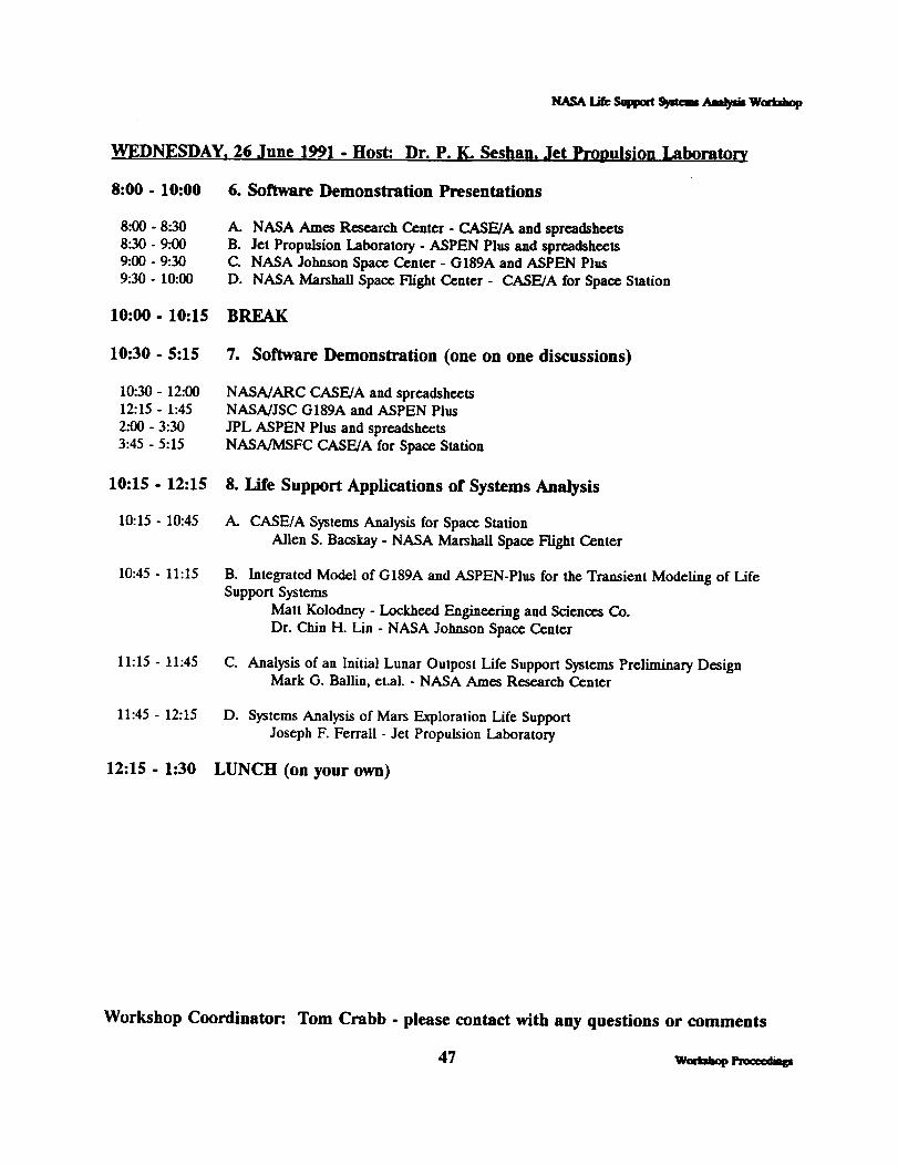
_ tae s_n ss_ _ w_
WEDNESDAY, 26 June 1991. Host: Dr. P. K. Seshan. Jet Propulsion Laboratory
8:00 - 10:00 6. Software Demonstration Presentations
8:00 - 8:30
8:30 - 9:00
9:00 - 9:30
9:30- 10:00
A. NASA Ames Research Center - CASE/A and spreadsheets
B. Jet Propulsion Laboratory - ASPEN Plus and spreadsheetsC. NASA Johnson Space Center - G189A and ASPEN Plus
D. NASA Marshall Space Flight Center - CASE/A for Space Station
10:00- 10:15 BREAK
10-.30 - 5:15 7. Software Demonstration (one on one discussions)
10:30- 12:00
12:15 - 1:45
2:00 - 3:30
3:45 - 5:15
NASA/ARC CASE/A and spreadsheetsNASA/JSC G189A and ASPEN Plus
J-PL ASPEN Plus and spreadsheets
NASA/MSFC CASE/A for Space Station
10:15 - 12:15 8. Life Support Applications of Systems Analysis
10:15 - 10:45 A. CASE/A Systems Analysis for Space Station
Allen S. Bacskay - NASA Marshall Space Flight Center
10:45 - 11:15 B. Integrated Model of G189A and ASPEN-Plus for the Transient Modeling of LifeSupport Systems
Matt Kolodney - Lockheed Engineering and Sciences Co.
Dr. Chin H. Lin - NASA Johnson Space Center
11:15 - 11:45 C. Analysis of an Initial Lunar Oulpost Life Support Systems Preliminary DesignMark G. Ballin, et.al. - NASA Ames Research Center
11:45- 12:15 D. Systems Analysis of Mars Exploration Life Support
Joseph F. Fen'all - Jet Propulsion Laboratory
12:15 - 1".30 LUNCH (on your own)
Workshop Coordinator:. Tom Crabb - please contact with any questions or comments
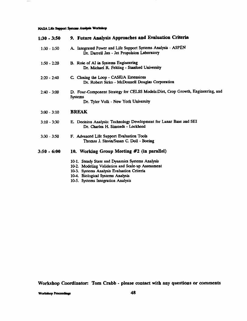
N,_ L_ Suppm S3_:_ ,'uat_i_ Wc_b_p
1".30 - 3:50 9. Future Analysis Approaches and Evaluation Criteria
1".30- 1:50 A. Integrated Power and Life Support Systems Analysis - ASPENDr. Dan'eU Jan - Jet Propulsion Laboratmy
1:50 - 2:20 B. Role of AI in Systems EngineeringDr. Michael tL Felling - Stanford University
2:20 - 2:40 C. Closing the Loop - CASE/A ExtensionsDr. Robert Sirko - McDonnell Douglas Corporation
2:40 - 3:00 D. Four-Component Strategy for CEILS Models:Diet, Crop Growth, Engineering, and
SystemsDr. Tyler Volk - New York University
3:00 - 3:10 BREAK
3:10 - 3:30 E. Decision Analysis: Technology Development for Lunar Base and SEIDr. Charles H. Simonds - Lockheed
3:30 - 3:50 F. Advanced Life Support Evaluation ToolsThomas J. Slavin/Susan C. Doll. Boeing
3:50 - 6:00 10. Working Group Meeting #2 (in parallel)
10-1. Steady State and Dynamics Systems Analysis10-2. Modeling Validation and Scale-up Assessment10-3. Systems Analysis Evaluation Criteria10-4. Biological Systems Analysis10-5. Systems Integration Analysis
Workshop Coordinator:. Tom Crabb - please contact with any questions or comments
wea_ep _ 48

_ Lee SuCpm S_mm _ W,rh_¢
THURSDAY, 27 June 1991
8:00 - 10:50 11. Working Group Presentations
8:00 - 8:20 A. Steady State and Dynamics Systems Analysis8:20 - 8:40 B. Model Validation and Scale-up Assessment8:40 - 9:00 C. Systems Analysis Evaluation Criteria9:00 - 9:20 D. Biological Systems Analysis9:20 - 9:40 E. Systems Integration Analysis
9:40 - 10:00 Break
10:00 - 10:45 12. Panel Review of Workshop Conclusions and Future Systems Analysis
A. Vince Bilardo - NASA Ames Research Center
B. P.]C Seshan - Jet Propulsion LaboratoryC. Chin Lin - NASA Johnson Space CenterD. Alan Basckay - NASA Marshall Space Flight Center
10:45 - 11:45 13. Overview of NASA's Life Support Technology Program
10:45 - 11:15 A. P-C Life Support Project UpdateVince Bilardo - NASA Ames Research Centcr
11:15- 11:45 B. Lunar Base Life Support Test BedAl Behrend - NASA Johnson Space Center
Workshop Coordinator:. Tom Crabb - please contact with any questions or comments
49 weeea_

THIS PAGE INTENTIONALLY LEFT BLANK
APPENDIX B l.ist of Workshop Participant_
51
PRECEDING PAGE BLANK NOT FILMED
50

THIS PAGE INTENTIONALLY LEFt BLANK
w__ 52

Allen S. Bacskay
Code ED62, Bldg T285
NASA Marshall Space F'fight CenterMSFC, AL 35812
(205) 544-0993
Mark G. Ballia
Code SAS, M/S 239-8NASA Ames Research Center
Moffett Field, CA 94035
(415) 604-5771
Mr. Michael Barrera
Aspen Technology, Inc.251 Vassar Street
Cambridge, MA 02139
(617) 497-9010
Dr. W.B. BedweU
Allied Signal
50 E. Algonquin Rd
Des Plaines, IL 60017-5016
(708) 391-3500
Albert F. Behrend, Jr.
NASA Johnson Space Center
2101 NASA Road 1, CODE EC3Houston, TX 77058
(713) 483-9241
Dr. Lawrence BeiglerMCS Division
Argon, IL 40439
Mr. Vincent Bilardo
Code SAS, M/S 239-8NASA Ames Research Center
Moffett Field, CA 94035
(415) 604-5752
Dr. Attilio Bisio
ATRO Associates
Box 1367
Mountainside, NJ 07092
(908) 233-1524
53
g_SA t._ saptam S,_aam Aaa_,m W_
Dr. Ray Bula
University of Wisconsin
1357 University Avenue
Madison, WI 53715
(6o8)262-5526
Mr. Mel Cobb
Lockheed Missiles & Space CompanyP.O. Box 3504, ORG 6N-12/B580
Sunnyvale, CA 94088-3504
(408) 756-6832
Ms. Carolyn Cooley
Martin Marietta Civil & Space CommP.O. Box 179, M/S DCS001
Denver, CO 80201
(303) 971-9375
Mr. Thomas M. Crabb
Orbital Technologies Corporation402 Gammon Place, Suite 10
Madison, WI 53719
(608) 833-1992
Mr. Robert DaLee
McDonnell Douglas Space Systems Co
689 Discovery Drive, Mail Code 12C3Huntsville, AL 35806
(205) 922-7320
Ms. Susan Doll
Boeing Aerospace CompanyP.O. Box 240002, M/S JX-23
Huntsville, AL 35824-6402
(205) 461-3731
Dr. Alan Drysdale
McDonnell Douglas Space SystemsP.O. Box 21233
Kennedy Space Center, FL 32815(407) 383-3819
Peggy L. EvanichOAST, Code R
NASA Headquarters
Washington, DC 20546
(202)453-2843
PRECEDING PAGE 5LANK NOT FILMED
W,=ri,,i_ Pm==,_

Martha EvenLockheed/ESC2400 NASA Rd 1, MC-CA4Houston, TX 77058
(713) 244-5111
Dr. Michael FeldingTerman Engineering CemerStanford UniversityStan/ord, CA 94305-4025
(415) 723-o344
Mr. Joseph FcrraUJet Propulsion Laboratory4800 Oak Grove Drive, M/C 125-224Pasadena, CA 91109
(818) 354-3159
Mr. John F_sherCode SAR, M/S 239-11NASA Ames Research Center
Moffett Field, CA 94035
(415) 604-4400
Ms. Susan FuhsAIResearch
P.O. Box 2960, M/S T-41Torrance, CA 90509-2960
(213) 512-4600
Dr. Gani B. Ganipath/Jet Propulsion Laboratory4800 Oak Grove Dr, M/S 125-224Pasadena, CA 91109
(818) 354-7449
Scott GilleySverdrup Technology, NASA LeRC21000 Brookpark Road, M/S 309-1Cleveland, OH 44135
(216) 433-6137
Mr. Ian GoslingAspen Technology, Inc.251 Vassar Street
Cambridge, MA 02139(617) 497-9010
Mr. Stephen Gustavino
McDonnell Douglas Space Systems Co5301 Bolsa Avenue, Mail Code 17-B
Huntington Beach, CA 92647(714)896-3311
Mr. Joseph HomaHamilton Standard
One Hamilton Road, M/S 1A-2-W66Wiadsor Locks, CT 06096
(2o3)654-2495
Vibhor Jain
Bionetics CorporationNASA Ames Research Center, MS 239-8
Moffett Field, CA 94035(415) 604.1335
Darrell Jan
Jet Propulsion Laboratory4800 Oak Grove Drive, M/C 125-224Pasadena, CA 91109
Mr. Matthew KolodneyLockheed Engineering & Science Co2400 NASA Road 1, M/C C70Houston, TX 77058
(713) 333-7224
Mr. Richard LamparterNASA Ames Research Center
Marl Stop 239-11Moffett Field, CA 94035
(415) 604-1159
Mr. William Likens
Code SAS, M/S 242-4NASA Ames Research Center
Moffett Field, CA 94035(415) 604-3210
Cheng-Hsiung LinPurdue UniversityLorre/Potter Center, Rm 220
West Lafayette, IN 47907(317) 494-7027
Wom_op _ 54

NASA Lie Sappm Ssqaemamb_ W_
Dr. Chin Lin
NASA Johnson Space Center2101 NASA Road 1
Houston, "IX 77058(713) 483-9126
Thomas M. MaloneySverdrup Technology, NASA LeRC21000 Brookpark Road, M/S 309-1Cleveland, OH 44135(216) 433-6137
Dr. David Ollis
Chemical Engineering DepartmentNorth Carolina State UniversityRaleigh, NC 27695(919) 737-2329
Dr. Firooz Rasouli7449 N. Natchez Avenue
Niles, IL 60648-3892(312) 647-9000
Mr. Barney RobertsNASA Johnson Space Center2101 NASA Road 1, Code IE2Houston, TX 77058
(713) 283-5460
Dr. Narcsh RohatgiNASA Jet Propulsion Laboratory4800 Oak Grove Drive, M/S 125-224Pasadena, CA 91109(818) 354-3073
Dr. Willy Sadeh
Department of Civil EngineeringColorado State UniversityFort Collins, CO 80523(303) 491-2001
Nelson Schlater
Bionetics CorporationNASA Ames Research Center, MS 239-8Moffett Field, CA 94035(415) 604-1335
Dr. Richard SeagraveIowa State UniversitySweeney HaIL Room 238Ames, IA 50011
(515) 294-0518
Dr. P.K. Seshan
NASA Jet Propulsion Laboratory4800 Oak Grove Drive, M/S 125-224Pasadena, CA 91109
(818)354-7215
Dr. Charles Simonds
Lockheed Missiles and Space1150 Gemini Ave, M/C A23Houston, TX 77058(713) 282-6203
Dr. Kamalesh K. Sirkar
Stevens Institute of TechnologyCastle Point
Hoboken, NJ 07030
(201) 420-5432
Dr. Robert Sirko
McDonnell Douglas Space Systems Co5301 Bolsa Avenue, Marl Code 13-2
Huntiagton Beach, CA 92647(714)896-3817
Mr. Thomas Slavin
Boeing Aerospace & Electronics DivisionP.O. Box 3999, M/S 84-15Seattle, WA 98124(206) 773-1471
Mr. Paul SpurlockS&A Automated Systems, Inc.I23 NW 13th Street, 13th Floor, Ste 222Boca Raton, FL 33432
(407)750-8786
Dr. Ted Tibbitts
University of WisconsinRoom 327, HorticultureMadison, WI 53706
(608) 262-1816
55 woeahop rau,ma_

tta.sa tae s_z_ _em ,_a,_i_ weaat_
Mr. William Trail
Aspen Technology, Inc.251 Vassar Street
Cambridge, MA 02139(617) 497-9010
Raymond B. TruschHamilton StandardOne Hamilton Road
Windsor Locks, CT 06096
(203) 654-2495
Dr. George TsaoPurdue UniversityPotter Building- 1295West Lafayette, IN 47907(317) 494-7022
Dr. Tyler VolkNew York University26 Stuyvesant StreetNew York, NY 10003(212) 998-8995
Raymond IVLWheelerNASA Kennedy Space CenterCode MD-RES
Kennedy Space Center, FL 32899(407) 853-5142
Dr. Lionel R. Whitmer
Boeing Missiles and Space DivisionP.O. Box 240O02,M/S JR-34Huntsville, AL 35824-6402
(205) 4614854
Mr. Versie L. Wilson
Boeing Mhsiles and Space DivisionP.O. Box 240O02, M/S JR-34Hantsville, AL 35824-6402
(205) 461-5822
Dr. Bruce WrightBoeing Missiles and Space Division499 Boeing Blvd, M/S JR-34P.O. Box 240002
Huntsville, AL 35824-6402(205) 461-5822
WORKING GROUP SUPPORT
Antholly J. Keillctltl (Orbital Technologies Corporation)Darin R. Kohles (Orbital Technologies Corporation)
Jan/s M. Moths (Orbital Technologies Corporation)Dr. Thomas L Woodzick (Orbital Technologies Corporation)
WORKSHOP SuppORT
Marcia McDevitt (General Research Corporation)Marie L Davis (Orbital Technologies Corporation)
weeal_ l'mceeat_ 56
APPENDIX C Original Working Group Presentations
C.1
C.2
C.3
C.4
C.5
Working Group 1:
Working Group 2:
Working Group 3:
Working Group 4:
Working Group 5:
Steady State and Dynamics Systems Analyses
Modeling Validation and Scale-Up Assessment
Systems Analysis Evaluation Criteria
Biological Systems Analysis
Systems Integration and Analysis
57 w, xJ_ _
THIS PAGE INTENTIONALLY LEFT BLANK
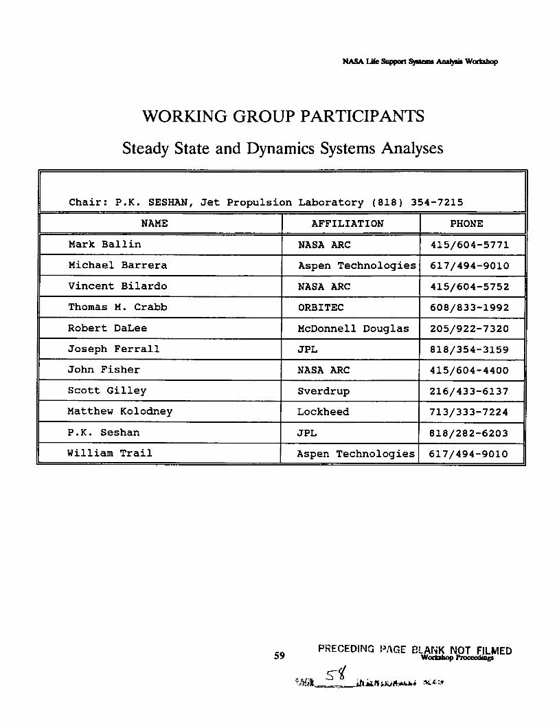
WORKING GROUP PARTICIPANTS
Steady State and Dynamics Systems Analyses
Chair: P.K. SESHAN, Jet Propulsion Laboratory (818) 354-7215
NAME AFFILIATION PHONE
Mark Ballin NASA ARC 415/604-5771
Michael Barrera Aspen Technologies 617/494-9010
Vincent Bilardo NASA ARC 415/604-5752
Thomas M. Crabb ORBITEC 608/833-1992
Robert DaLee McDonnell Douglas 205/922-7320
Joseph Ferrall JPL 818/354-3159
John Fisher NASA ARC 415/604-4400
Scott Gilley Sverdrup 216/433-6137
Matthew Kolodney Lockheed 713/333-7224
P.K. Seshan JPL 818/282-6203
William Trail Aspen Technologies 617/494-9010
59PRECEDING PAGE I_LANK NOT FILMED
w__

THIS PAGE INTENTIONALLY LEFT BLANK
wottamp _ 60

WORKING GROUP: STEADY STATE AND DYNAMIC SYSTEMS ANALYSES
ISSUES IDENTIFIED: Need for additional generic modules in simulation
software packages
OBSERVATIONS"
RECOMMENDATIONS:
CONTRIBUTORS:
ASPEN Plus and CASE/A have many modules, not always
genetic in the case of CASE/A. However, some modules needed
for life support systems are not built in. ASPEN Plus provides for
custom building of new modules. The names of many of the
LS process units and unit operations are not genetic but could
be expressed in terms of one or more built-in generic modules
of software packages.
Genetic modules needed:
Electrochemical reactor
Ion exchange
Membrane SeparatorPlant
Metabolic man/woman
Kitchen
Dishwasher
Clothes washer
Clothes drier
Toilet
Shower
Metabolic animal
Bioreactors(various kinds)
Specific module needed:
More rigorous VCD model for CASE/A
On module development by users:
Agree on module structure/interfaces
Share modules and avoid duplication of effort
John Fisher, Tom Crabb, Joe Ferrall, Michael Barrera, P. K.Seshan
61PRECEDING PAGE BLANK NOT FILMED
wo,t=l=,pl'm==l_

WORKING GROUP: STEADY STATE AND DYNAMIC SYSTEMS ANALYSES
ISSUES IDENTIFIED: Need for rigorous dynamic simulation in life support systems
analysis
OBSERVATIONS:
RECOMMENDATIONS:
CONTRIBUTORS:
CASE/A,G189A,SPEEDUP and SIMTOOL have combined
steady state and dynamic simulation capabilities. ASPEN Plus
can simulate transient performance of individual blocks by the
using RBATCH and custom code modules capable of executing
sophisticated integration algorithms.
CASE/A and G189A do not contain the standard tools for
control system analysis (analysis of performance dynamics).
MATRIX, System Build and MATLAB are control system
design/analysis packages. However, they are not chemical
process simulation packages. Only one commercial chemical
process simulator, SPEEDUP by Prosys Technology, can
simulated dynamics within a block and across an entire flow
sheet using sophisticated integration methods, but probably not
very user friendly.
Rigorous dynamic simulations are needed for system response
and controllability studies, for control system design and testing and
not for systems analysis. Rigorous dynamic simulations are
not needed during conceptual system studies and technology
development. They have little relevance to system parameters such
as weight, volume, power demand etc.
Quasi-steady state simulation capability in ASPEN Plus
particularly to monitor changes in storage tanks.
Rigorous dynamic simulations must be part of the design review
process especially for transient thermal response of process
equipment including highly exo/endothermic chemical reactors.
Since early concept definition must also include definition of
control strategies, use dynamic simulations even at the
conceptual stage.
V. L. Wilson, Scott Gilley, Michael Barrera, John Fisher, Joe
Ferrall, Matt Koiodney, Tom Crabb, P. K. Seshan
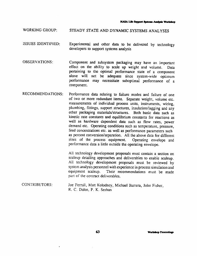
_t_._Lik Samara _ ,_a_m waaaamp
WORKING GROUP: STEADY STATE AND DYNAMIC SYSTEMS ANALYSES
ISSUES IDENTIFIED: Experimental and other data to be delivered by technology
developers to support systems analysis
OBSERVATIONS: Component and subsystem packaging may have an important
effect on the ability to scale up weight and volume. Data
pertaining to the optimal performance state of a component
alone will not be adequate since system-wide optimum
performance may necessitate suboptimal performance of a
component.
RECOMMENDATIONS: Performance data relating to failure modes and failure of one
of two or more redundant items. Separate weight, volume etc.
measurements of individual process units, instruments, wiring,
plumbing, fittings, support structures, insulation/lagging and any
other packaging materials/structures. Both basic data such as
kinetic rate constants and equilibrium constants for reactions as
well as hardware dependent data such as flow rates, power
demand etc. Operating conditions such as temperature, pressure,
feed concentrations etc. as well as performance parameters such
as percent conversion/separation. All the above data for different
sizes of the process equipment. Operating envelope and
performance data a little outside the operating envelope.
All technology development proposals must contain a section on
scaleup detailing approaches and deliverables to enable scaleup.
All technology development proposals must be reviewed by
system analysis personnel with experience in process simulation and
equipment scaleup. Their recommendations must be made
part of the contract deliverables.
CONTRIBUTORS: Joe Ferrail, Matt Kolodney, Michael Barrera, John Fisher,
R. C. Dalee, P. K. Seshan
63 w__

WORKING GROUP: STEADY STATE AND DYNAMIC SYSTEMS ANALYSES
ISSUES IDENTIFIED: Property data for trace contaminant control modeling
OBSERVATIONS: ASPEN Plus contains a large database and can calculate propertiesbased on molecular structure and can track trace chemicals in the
model by setting extremely tight tolerances on convergence.
Trace contaminants such as methane and carbon monoxide may also
affect the life cycle and size of the Bosch unit and must be
accurately accounted for.
RECOMMENDATIONS: Obtain kinetic data for trace contaminants not found in the ASPEN
Plus database, either through literature search or through
experiments. Since possible contaminants are too numerous to
model and track in a any simulation, organize them into not more
then ten classes and select a representative compound for each class
for modeling trace contaminant processes in life support systems
CONTRIBUTORS: Joe FerraU, Matt Kolodney, R. C. Dalee, Michael Berrara, John
Fisher, P. K. Seshan
w,=l,,i_ _ 64

WORKING GROUP: STEADY STATE AND DYNAMIC SYSTEMS ANALYSES
ISSUES IDENTIFIED: Effect of micro/partial gravity on thermodynamic, transport and
kinetic properties
OBS ERVATIONS: Several contractor and NASA reports available on the subject
of the effect of microgravity covering components and subsystems
that are and aren't affected. LESC '90 report includes many of
the governing equations. Gravity affects transport processes;
thermodynamic properties are not expected or known to be
affected by the magnitude of gravity. Finely divided particles,
bubbles and droplets could exhibit gravity dependence on
equilibrium properties due to high surface energy; however, these
are often avoided in microgravity environments due to phase
separation problems. Often life support processes are likely to
be designed to be independent of the gravity environment or
generate their own gravitational fields.
RECOMMENDATIONS: Conduct a workshop of experts in properties measurements to
identify potential experiments to be conducted in microgravity
environments to generate a microgravitational property database
of interest to life support systems.
Retrofit a KC-135 type aircraft with an automatic trajectory
control system to minimize gravity and maximize duration in low
gravity to conduct reproducible property measurement
experiments.
Plan, establish and fund a program of chemical and physical
properties measurements on the SSF.
CONTRIBUTORS: Matt Kolodney, R. C. Dalee, Tom Crabb, Mark Ballin, Joe
Ferrall, Michael Barrera, P. K. Seshan

WaSA Lir_ Samm S,_amm.,ma,_ w_
THIS PAGE INTENTIONALLY LEFT BLANK
wonanop _ 66

WORKING GROUP PARTICIPANTS
MODELING VALIDATION AND SCALE-UP ASSESSMENT
CHAIR: CHIN LIN, NASA Johnson Space Center (713) 483-9126
NAME AFFILIATION PHONE
W.B. Bedwell Allied Signal 708/391-3463
Mel Cobb Lockheed 408/756-0261
Vibhor Jain NASA Ames 415/960-9477
Darin Kohles ORBITEC 608/833-1992
Chin Lin NASA JSC 713/483-9126
David Ollis N. Carolina State 919/737-2329
Firooz Rasouli Chamberlain Gard 708/647-3244
Kamalesh K. Sirkar Stevens Institute 201/420-5432
Versie L. Wilson Boeing 205/461-5822
67
PRECEDIb!G PAGE BLANK NOT FILMED
wod=l=_ _

!
THIS PAGE INTENTIONALLY LEFT BLANK

_m.sA tat_ s_t_a s_n, _ wae,_l,
Modeling Validation and Scale-Up Assessment Working Group
PROTOTYPE AND TEST BED REOUIREMEN'I_
RECOMMENDED APPROACH:
Build and Test Prototypes at Incremental Levels up to No Lessthan xAof Flight Hardware
Different Missions may Require Different Levels ofPrototype
Need Test Beds at Both Component and Integrated SystemLevels
69
PRE_,EOlI_ H.qGE bt.ANK NOT FILI_ED

Modeling Validation and Sc_e-Up Assessment Working Group
DATA COLLECHON REOUIREMENTS
RECOMMENDED APPROACH:
Continue Expansion and Enhancements of the ExistingCentralized Database to Incorporate, all Hardware andTest Data Relevant to Modeling/Analysis
Make a Commitment to Acquire the Necessary Datafor Model Validation and Scale-Up
Establish a Generalized Protocol for Defining
Test Requirements for System Analysis
Modeling/Analysis Provides Influential Inputs
to Test RequirementsModeling/Analysis Provides Pre-TestPrediction
Modeling/Analysis Uses Test Data toCorrelate Models
Provide Sufficient Resources to Hardware Testing
Program to Obtain In-Depth Measurements OverWider Ranges
Modeling Validation and Scale-Up Assessment Working Group
SCALE-UP OF PROTOTYPE/TEST BED
RECOMMENDED APPROACH:
Use Test Data at Component Level to Support Scale-Up of Individual Component, Rather than DoingScale-Up at a Subsystem or System Level
Broaden Use of Validated Models/Analysis forHardware Scale-Up
Use More Dimension Analysis and Similitude Analysisto Support Scale-Up
71 w,_ffi_, _

Modeling Validation and Scale-Up Assessment Working Group
EFFECTS OF MICROGRAVITY AND PARTIALGRAVITY
RECOMMENDED APPROACH:
Re-Examine the Governing Equations Used in CurrentModels. Make Sure that G is Justifiably Negligible
Perform a Thorough Study to Identify Gravity-Sensitive Processes and Test Requirements for Newand Emerging Life Support Technologies
For Gravity-Sensitive Process, Perform Ground Tests
or Flight Experiments to Ascertain Gravity Effects
Centrifuge for Partial GravityKC-135, Shuttle and Station-Bases Tests for
Microgravity
woa,_ol, _ 72
NaSA L_ _ _ ,,ma,m_ w_
Modeling Validation and Scale-Up Assessment Working Group
VALIDATION TEST SERIES
RECOMMENDED APPROACH:
@ Use Rigorous Experiment Design Techniques toMaximize Return of Necessary Testing
For an Agency-Wide Group, Including Industry andAcademia, Formulate a Consistent and Comprehensive
Testing Strategy
73 w_mt,
N_._.t,_ .r_goaa_m Am',jmw_
Modeling Validation and Scale-Up Assessment Working Group
PROTOTYPE AND TF_T BED REOUIREMENTS
ISSUE: What Types of Hardware and Test Beds will be
Required for Model Validation and Scale-Up?
CURRENT STATUS:
0 Most Hardware Data for Existing Life SupportTechnology are Known at:
- Bench-Top (Bread Board) or Pre-PrototypeLevel
- One Size Design
Test Beds Only Exist at Component andSubsystem Levels
Integrated System-Level Test Beds, with PrototypeH/W, are in Planning
w_ _ 74

NASA Lil'c SUplX_rxSy_cms Analysis W(x,i_J,op
Modeling Validation and Scale-Up Assessment Working Group
DATA COLLECTION REQUIREMENTS
ISSUE: Are Hardware and Test Data Being Collected, Reported,
and Organized in an Efficient Manner to Support ModelValidation and Scale-Up?
CURRENT STATUS:
A Centralized Life Support System Technology Databasehas been established at Ames Research Center.
- Completeness?
Substantial P/C Technology Data have been Collected by
Boeing; Bioregenerative Technology Data by LMSC- Accessibility?
Lack of Detail Break-Down Hardware Data at Part Level
to support Validation of Scale-Up Correlation
Incomplete Fundamental "Driving Mechanism" Data toSupport Validation of System Performance Model
Component- and Subsystem-Level Test Data are RatherLimited in Range and Number of Parameters
7_ W(_..dM_ I'nx:tnlinp
Modeling Validation and Scale-Up Assessment Working Group
SCALE-UP OF PROTOTYPE/TEST BED
ISSUE:
• What Analysis Techniques Should Be Used?
• Are Available Data Adequate?
How to coordinate Modeling/Analysis withHardware Scale-Up
CURRENT STATUS:
Prototype/Test Bed Data Mostly Exist at aCapacity Up To 4-Man. This is not Adequate toAccurately Scale-Up a Subsystem to a LargerCapacity Level (> 16-Man)
Test Data are Not Usually Collected to SupportScale-Up Assessment
Dimension and Similitude Analysis Techniqueshave been Used, but Not Across-the-Board
Hardware Scale-Up and Modeling/Analysis areOften Conducted in Parallel and Independently
w,,e,a_ _ 76

Modeling Validation and Scale-Up Assessment Working Group
EFFECTS OF MICROGRAVITY AND PARTIAl.GRAVITY
ISSUE: How to Validate Models and Scale-Up Analysisfor Life Support System in a Micro- or Partial-Gravity Environment
CURRENT STATUS:
• Gravity is Not an "Explicit Parameter"
Models and Analysis are Validated with Earth-Based Ground Test Data
Independent Studies have been Performed to
Identify Processes in Life Support Systems whichare Sensitive to Gravity
Some Components and Subsystems have beenTested in Different Orientation on Earth to Drive
Out Gravity Effects
Shuttle- or Space Station-Based FlightExperiments have been Planned/Proposed toAscertain Gravity Effects.
77 W,_daq,

_sA i._ sawms_ _ woma_
Modeling Validation and Scale-Up Assessment Working Group
THIS PAGE INTENTIONALLY LEFT BLANK
wom_,_p l_c,_t_ 78

WORKING GROUP PARTICIPANTS
SYSTEMS ANALYSIS EVALUATION CRITERIA
CHAIR: ALLEN BACSKAY, NASA Marshall Space Flight Center
NAME
Allen Bacskay
Susan Doll
Alan Drysdale
Martha Evert
Joe Homa
Willy Sadeh
Nelson Schlater
Charles Simonds
Paul Spurlock
Thomas L. Woodzick
AFFILIATION
NASA MSFC
Boeing Aerospace
MDSSC-KSC
Lockheed
Hamilton Standard
Colorado State U.
Bionetics
Lockheed
S&A Automated Sys
ORBITEC
(205) 544-0993
PHONE
205/544-0993
205/461-3731
407/383-3819
713/244-5111
203/654-3890
303/491-2001
415/604-1335
713/282-6803
407/750-8786
608/833-1992
79
PRECEDING i'AGE BLANK NOT FIL_ED

NASA titc _ S',/m:_ _ W_p
THIS PAGE INTENTIONALLY LEFT BLANK
wc_a_p t_=_ti_ 80

Systems Analysis Evaluation Criteria Working Group
RECOMMENDATIONS:
Relate Criteria To Single Accountable Unit• Take Away Subjective Decision Making
Set Up Working Group Meeting with All
Environmental Control Life Support System (ECLSS)Disciplines to Define Issues
• Issues Vary Depending on ECLSS Function
Distribute Current Evaluation Criteria to All
Participants Prior to Meeting
Result of Meeting to be Mutually Accepted Methodfor Evaluation Independent of Mission Type/Duration
81
FRE¢EDiNG PAGE BLANK NOT FILL'IED
Wod=aop
;/h
Systems Analysis Evaluation Criteria Working Group
WORKING GROUP GOAL:
• Criteria Definition
• Levels of Detail
OVERVIEW OF DISCUSSION:
• Day 1
Accomplishments- Criteria Definition (System Level)
• Day 2
• Restructure Working Group Goal
Definition of Strategies- Decision Analysis- Lockheed Space Exploration Initiative Manual
w_ _ 82

Systems Analysis Evaluation Criteria Working Group
MODEL EVALUATION CRITERIA
GOAL: Define Clear Objective Criteria which can be Applied to Diverse
Options (e.g., Physicochemical with Supplied Food vs.
Bioregenerative)
• Should Roll Up From Components to Subsystems to Systems, etc.
• Applicable to All Missions
RECOMMENDATIONS:
Analyses must be Based On Objective, Testable Requirements
Models must be Able to Predict Outputs for All Requirements, WithinNecessary Accuracy
All Criteria must be Reduced To Common Units.
Requirements/Not) and Cost
The Recommended Criteria is Life Cycle Cost.
- Program Criteria- Architecture Criteria
- System Criteria
Binary Decision (Meet
This can be Used As the:
- Subsystem Criteria- Component Criteria
Care Must Be Taken to Ensure All Cost Discriminators have been Included
Sub-Elements of Life Cycle Cost Include:
- Resupply Cost- Scarring- Volume- Cost of In-Situ Resources
- Mass Delivery Cost
- Power and Cooling Cost- DDT&E Cost
- Manpower Cost-Crew Time
83 Waa_bap Pt_a_=

NAS,'.Litc.r_nK_ts_a:_ .,u_)u w_
Systems Analysis Evaluation Criteria Working Group
LIFE CYCLE COST (LCC)
ADVANTAGES
Common Unit: Implicitly Supports Mass/Power Trade-Offs
Applicable To Any Objective Requirement/ResourceForces Program To Make Assumptions Explicit -- Costis As Important As Performance
Can be Used From Program To Program
Can be Used Throughout Program, Accuracy Growingas Program Proceeds from Phase A, Phase B, PhaseC/D, and Into Operation
DISADVANTAGES
Political/Programmatic Sensitivity to Cost
Uncertainty Associated With Some Requirements SuchAs Safety, ReliabilityExisting DOD LCC Estimation Methods/Tools must
be Used With Caution as they are Designed forSupport of Systems Involving Many Units (e.g., 960 F-16s). There are only Four Shuttles, One Space Station

Systems Analysis Evaluation Criteria Working Group
STANDARD INPUTS TO ARCHITEC-qqJRE ANDSYSTEM-LEVEL EVAI.UATION MODELS
Mission Parameters, e.g.:
• Crew Size (4)
• Duration (90 days)
• Location (Lunar Surface)
Top Level Performance of Other Systems, e.g.:
• Cost of Mass Delivery to Point of Use (Moon Surface) ($ per pound)(50K)
• Cost of Power at Point of Use ($ per Kilowatt-Hour)
• Cost of Crew Time at Point of Use ($ per Man-Hour)• Cost of Lunar Oxygen ($ per pound)
Absolute and/or Allocated Resource Limits, e.g.:
• Maximum Average Use of Crew Time = 1 person out of Crew of 4
Standards to be Used, e.g., JSC STD 3000
Requirements to be Met, e.g.:
• Use of Space Shuttle for Delivery of Space Station to Orbit
85 wae,_,,0 _a_,xumo

Systems Analysis Evaluation Criteria Working Group
RECOMMENDED METHODOLOGY
• Establish Requirements Including Safety, Reliability
Develop Scenario and Design to Meet Requirements -
Several Options
• Develop Life Cycle Cost for Each Option
Identify Drivers for Interfaces With Other Systems,e.g., Unusual Duty Cycles, Mass Requirements/Surplus
w_ l,t_nxu.o 86

.System Analysis Evaluation
Define
Requirements
• Mission• Standards
• Requirements
V
b
Develop
Scenario
Run Model/
Simulate Mission
V
Develop
Design
• Concept• Preliminary• Detail• Mods
Develop
Model
,11
Define Cost Factors/
Life Cycle Cost
v
Repeat For
Other Options
V
Select Lowest
Cost Option
87 w=_ _,_

Systems Analysis Evaluation Criteria Working Group
Life Cycle 1Cost[
DDT & E Operations Support
• Design Cost• Fabrication Cost
(Depends on #)(Mass, Complexity,
Technology Readiness,
Requirement vs. SOA)
Concept DefinitionPhase A
Concept Development
(Prelim Design) Phase B
Detail Design
Phase C/D
OperationsPhase O
• Operations Cost
(Mass, Delivery Cost,Power, Power Cost,
Manpower, ManpowerCost, Consumables Cost)
• Maintenance/Maintainability
• Repair• Refurbishment
• Support Cost
What is the ROM Cost of Architecture Options?
system model and derive mass, power, etc.
(Resupply Mass, CrewTime, Support EquipmentMass, Volume, Power)
Run system
What is ROM Cost of System/Subsystem Options? Run
subsystem model, derive mass, power, etc. Derive ROM 1/Fcharacteristics.
what is performance of Design? Run model to
verify design compliance.
what is cost of design changes? Run model of change, verify
design compliance, estimate delta cost.
What is most likely cause of problem? Simulate potential
problems. Did model predict actuals? Try out mods. Verify
design compliance, estimate cost.
What are impacts of proposed changes?
Wo.-C_opProcc_in_ 88

_m.sA Li_ _ S3,tmm _ Woa_,
Systems Analysis Evaluation Criteria Working Group
SYNOPSIS
KEY ISSUES:
• Disorganization of Judgment
Decisions Must Be Made Today Without Knowing Precisely What the
Mission Will Be and Consequently What Problems Need to be Solved
Decisions Which Look Good on the Surface Can Actually be Seriously
Misguided Without Having All Interests Well Understood
"If You Can't Identify What You Want, the Results of Your Analysis Will
be Meaningless"
PRESENT METHODOLOGY TO ADDRESS ISSUES
A Well-Validated and Structured Methodology has been Developed in theDecision Analysis Community for Making Strategic Decisions. This exists in
Several Areas of Industry and Private Sector
RECOMMENDATIONS
Establish Workshop with Various Interested Groups, Experts, etc., toProduce a More Coherent View of the Issues at Hand
• Provide Background Info to Workshop Participants to Allow
Preparation
• Make Individuals "Mix It Up" to Find a Way to Raise It Above the
Ground and Develop Compromises• Identify and Suggest Industrial Methodologies for Strategic Decision
Analysis (at the Workshop)
• Establish a Set of Evaluation Standards (Perhaps)
89 WorlU_u_

Systems Analysis Evaluation Criteria Working Group
EVALUATION CRITERIA AND ITS WEIGHTING
ISSUE:
Evaluation criteria identified as critical at the "subsystem" level may be
misrepresented or overweighted when all subsystems are compared at the "system"level (example: if an evaluation criterion should be de-weighted by all subsystem
analysis efforts). Listing criteria by system, subsystem and processor could be
extremely misleading unless system-level data is available in order to help
determine the weighting factors--if system level data changes, the individual
evaluation criterion's weighting would need to be changed.
RECOMMENDED APPROACH:
Decide Level to be Evaluated:
_, System Level - "Best" Life Support System for a Particular Application
_, Subsystem Level - Which Technology Does a Better Job of RecyclingWater?
• Examine List of Criteria and Define Terms
Make Recommendation to Develop "Common Units" to Compare Power,Mass, Volume
Recommend that a Process and Standard Set of Evaluation Criteria be
Adopted by NASA and Used by the Life Support Community
Wct_thop_ 90

N_._ _re Summ_ Symes ,_uma--._isWo_mUop
Systems Analysis Evaluation Criteria Working Group
WORKING GROUP PARTICIPANTS
Biological Systems Analysis
Chair: RAYMOND M. WHEELER, NASA Kennedy Space Center (407) 853-5142
NAME AFFILIATION PHONE
Ray Bula Univ of Wisconsin 608/262-5526
Carolyn Cooley Martin Marietta 303/971-9375
Alan Drysdale McDonnell Douglas 414/821-0903
Gani B. Ganapathi JPL 818/354-7449
Ian Gosling Aspen Technology 617/494-9010
Stephen Gustavino McDonnell Douglas 714/896-3311
Janis Moths ORBITEC 414/821-0903
Dick Seagrave Iowa State Univ 515/294-0518
Robert Sirko McDonnell Douglas 714/896-3817
Ted Tibbitts Univ of Wisconsin 608/262-1816
George T. Tsao Purdue University 317/494-7022
Tyler Volk New York Univ 212/998-8995
Raymond Wheeler NASA KSC 417/853-5142
Bruce Wright Boeing 205/461-5822
91 Woam_p Pmanxfings

R,gSA L_ Sat_am Sya=_ Am_i. Wamamp
Systems Analysis Evaluation Criteria Working Group
THIS PAGE INTENTIONALLY LEFT BLANK
woaahop enx_ti_ 92

Biological Systems Analysis Working Group
PRIMARY PRODUCTION
ISSUE: Availability of Data for Primary Production fromBiological Systems (i.e., plant and/or algae growthand productivity)
CURRENT STATUS:
• Food/Biomass Production--Good/Extensive Data
• H20 Transpired (Distilled) -- Extensive Data
COz Removed
• Some Direct Measurements (e.g., Kennedy SpaceCenter Biomass Production Chamber [BPC])
• Extensive Data from Biomass Calculations
02 Produced• Few Direct Measurements (e.g., KSC BPC)• Can be Estimated From Biomass Production Data
Extensive Environmental Response Data (but not allconducive to response surface analyses).
• Contaminants -- Very Little Data (Trace)
Gravitational Effects -- Very Little Data
93 g _..._ ,_ w e_, _=d_
PRECEDING PAGE _LAi',_K NOr FILIViEL)

Biological Systems Analysis Working Group
WA_g/E TREATMENT/RESOURCE RECOVERY
ISSUE: Availability of Waste Treatment/Resource RecoveryData from Biological Systems
CURRENT STATUS:
• Cellulose Conversion -- Limited Data/Bench-Top Level
• Aerobic Treatment Systems -- Little Data
• Anaerobic Treatment Systems -- Even "Less" Data
Biomass Leaching to Recover Minerals -- LimitedData
Aquaculture/Animal Systems for Conversion ofInedible Biomass -- Limited Data
Gravitational Effects on Biological Waste TreatmentSystems -- No Data Available
NOTE: Commercial Technologies and Data Available fromSystems with Aerobic/Anaerobic Treatment (e.g., SewageTreatment Plants)
woeaal_ l,_._am_ 94

Biological Systems Analysis Working Group
ENERGY REOUIREMENTS
ISSUE: Availability of Energy Requirements for BiologicalSystems for Life Support
CURRENT STATUS:
Plant Lighting -- Good Data on Irradiance LevelsWhich Can be Used to Calculate Connected Power
Requirements
Heating, Ventilation and Air Conditioning (HVAC) --Few Data from Direct Measurements, but GoodEstimates Should be Obtainable
Water Pumping-- Again, Few Direct Measurements,but Estimates are Easily Obtainable. This Will BeMuch Less than Lighting/HVAC Requirements
Waste Treatment Systems -- Few Data Available onBiological Systems as Applied for Human Life Support

Biological Systems Analysis Working Group
MASS REOUIREMENTS
ISSUE: Mass Requirements for Biological Systems for PrimaryProduction and Waste Treatment
CURRENT STATUS:
• Plant Culture System
Few Data Reported, but Should be ObtainableGood Data on Area/Volume Requirements (e.g.,Crop Productivity) Which Should UltimatelyDictate System Mass Requirements
• Biological Waste Treatment/Resource Recovery
Few Data Available
Some Data on Water Volume/Mass Requirementsfor Aquaculture Systems for Conversion ofInedible Biomass

_ t._ sul_a Symm ,,u_jm Wor_nop
Biological Systems Analysis Working Group
PROBLEM: Lack of Consistent Approaches for Biological Life
Support System Testing
RECOMMENDED APPROACH:
Define Critical Inputs and Outputs and ControllingFactors
Consider Response Surface Approaches, Rather Thanmerely Defining Optimum Levels
• Employ Statistical Tools to Handle Variability
NOTE: The Above Should Apply to Both Primary ProductionSystems (i.e., Plants or Algae) and Waste Management andResource Recovery Systems
97 woa_J_p

Biological Systems Analysis Working Group
PROBLEM: Lack of Data on Use of Biological Systems forWaste Management
RECOMMENDED APPROACH:
Establish the Mass, Power, and Volume Requirements
for the operation of Biological Waste TreatmentSystems
Initiate Testing of Various Biological Waste Treatmentand Resource Recovery Systems to Generate DataUseful in Modeling System Operation
w,mm,_ _ 98

_dA Lit_SWatS,Z_a_,'u*_ Wain,n,
Biological Systems Analysis Working Group
PROBLEM: Lack of Human Behavior Data with regard toPresence or Absence of Plants
RECOMMENDED APPROACH:
Conduct Extensive Literature Search for Human
Response/Behavior Studies Assessing the Benefits orProblems of Having Plants Nearby and/or Benefitsfrom Engaging in Horticultural Activities
Initiate Studies of Human Response and Behavior inLiving and Working Areas With and Without Plants,I.e., Psychological Benefits Studies
Factor Results from Literature and/or Surveys intoModeling Approaches Assessing the Advantages ofDifferent Life Support Systems
99 w_

I_,SA t_ Saptam S_m ._i_ WomamP
Biological Systems Analysis Working Group
PROBLEM: Lack of Information of Biological System
Operations under Microgravity
RECOMMENDED APPROACH:
Initiate Testing Program to Characterize Operationand Productivity of Biological System (Especially PlantProduction Systems) Under Microgravity, Through
Flight Experiments
w_ vma_u_ 100

NA.SAt,i_S_,n_NS_ _ Wae_,_
Biological Systems Analysis Working Group
PROBLEM: Lack of Data on Animal Systems for Use in
Waste Management
RECOMMENDED APPROACH:
Initiate Survey of Possible Animal (i.e., Other ThanMicrobiological) Options to Use for WasteConversion. Possible Options might include Fish,Poultry, and/or Insects to Convert Inedible PlantBiomass and Provide a Protein Supplement forHumans.
• Assess the Advantages and Disadvantages to Each
I01 wo,ta_p

Biological Systems Analysis Working Group
PROBLEM: Lack of Long-Term, Large-Scale Test Data
RECOMMENDED APPROACH:
Initiate/Continue Large-Scale Studies to Assess Scale-
Up Problems for Biological Systems
Initiate Long-Term Studies to Assess Performance ofBiological Systems Over Time
Wcdmhop_ 102

Biological Systems Analysis Working Group
ANCILLARY SUGGESTIONS:
Identify Power, Mass and Volume Requirements forPlant Cultural Activities, Harvesting, and FoodProcessing
Develop a Generic Repository for Biological SystemsData for Use in a Standard Modeling Approach
103 w_l,,il_ l,Tacnxu,_

_.sA Li_ samara symm Am6_ Womamp
Biological Systems Analysis Working Group
THIS PAGE INTENTIONALLY LEFT BLANK
wo_op Pr_ 104
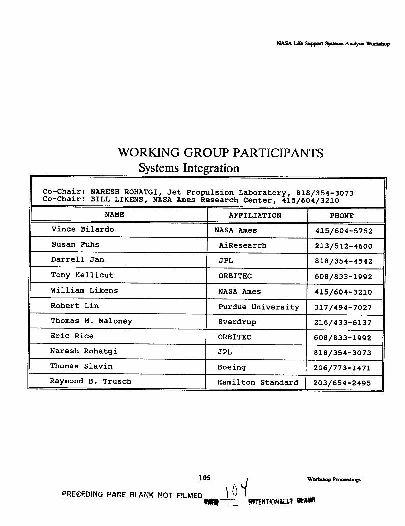
WORKING GROUP PARTICIPANTS
Systems Integration
Co-Chair: NARESH ROHATGI, Jet Propulsion Laboratory, 818/354-3073Co-Chair: BILL LIKENS, NASA Ames Research Center, 415/604/3210
NAME
Vince Bilardo
Susan Fuhs
Darrell Jan
Tony Kellicut
AFFILIATION
NASA Ames
AiResearch
JPL
ORBITEC
PHONE
415/604-5752
213/512-4600
818/354-4542
608/833-1992
William Likens NASA Ames 415/604-3210
Robert Lin Purdue University 317/494-7027
Thomas M. Maloney Sverdrup 216/433-6137
Eric Rice ORBITEC 608/833-1992
Naresh Rohatgi JPL 818/354-3073
Thomas Slavin Boeing 206/773-1471
Raymond B. Trusch Hamilton Standard 203/654-2495
105 ./ wo,_
PREeEDING PAGE BLANK NOT F,LMED / _

System Integration and Analysis Working Group
KEy PROBLEM AREAS
• Physical Interfaces
Identification of Material Interactions,
Technologies for Effecting BeneficialInteractions (see note)
• Integration Process
Standards: Materials, Commonality,Interfaces
Reliability and Risk Dependencies
NOTE: Chosen to be the current focus of the working
group.
wm'luamp_ 106
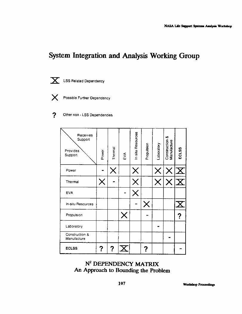
System Integration and Analysis Working Group
X LSS Related Dependency
X Possible Further Dependency
? Other non - LSS Dependencies
Receives
"_pp0rt "_ rre_ § o"_°_ . ,,ao=®
Provides _ _ E = "5 _ " _
Support _ o.°_ I-_'_ uJ<> __'--(_ 0.9_ _° ocj_:_ _JI,u
Power
Thermal
EVA
In-situ Resources
Propulsion
Laboratory
Construction &Manufacture
ECLSS
- X X XX"X
X - X XX_Z "
- X
X 'Z
X - 9
•_ _ -_- ?
N 2 DEPENDENCY MATRIX
An Approach to Bounding the Problem
107 womazp rmt:eed=_

l_sA Li_ Samm S_aam ,'.,a_ Woaaamp
System Integration and Analysis Working Group
ISSUES ADDRESSED:
• Power/Thermal System Integration
• Propulsion System Integration
In-Situ Resource Utilization Integration(Lunar and Mars Habitats)
• Laboratory Systems
• Construction and Manufacturing
• Extravehicular Activity (EVA) and Base Vehicles
• Existing Software
w_l_op enz_d_ 108

System Integration and Analysis Working Group
POWER
• Regenerative Fuel Cell
• Alkaline, Proton Exchange
Development: Advanced, Could be Flight-Ready in Five Years
Uses Fluids Common with Life Support
Systems: H20, 02, H2
Possibilities for Common Hardware,
Storage, Resource Sharing
• Other Power Technologies
Solid Oxide Fuel Cell (~10 Years UntilDevelopment)
• Nuclear
• Photovoltaic
109 w,_,_

System Integration and Analysis Working Group
THERMAL
• Heating and Cooling
• Heat Pipes, Heat Pumps, Radiator
Flight Ready
May Have Common Working Fluids (Water)
• High Efficiency Radiators
• Thermal Storage
• Sublimation of CaF, LiF
Lab-Scale Development (-10 Years untilDevelopment)
• Common Working Fluid (Water?)
Possibilities for Common Interaction
Water Sharing, Shared Storage, Air
wo,t_t, l,m,==t_ 110

System Integration and Analysis Working Group
PROPUI_ION
• Liquid H20, O2, H2
Possibility for Resource Sharing, CommonStorage
• Hydrazine Propulsion
N2H 4 Decomposition into N2, H2 a PossibleSource of Resource Usable by Life Support
Systems
Electric Propulsion-- Ion, Arcjet,Magnetodynamic Development: Advanced forIon, Arcjet
Life Support System Gases (H2, CH4, etc.)Could be used as Propellant
Other: Fusion Rockets, Nuclear Thermal
Propulsion
• Common Material: H 2 Propellant?
III w_ _._
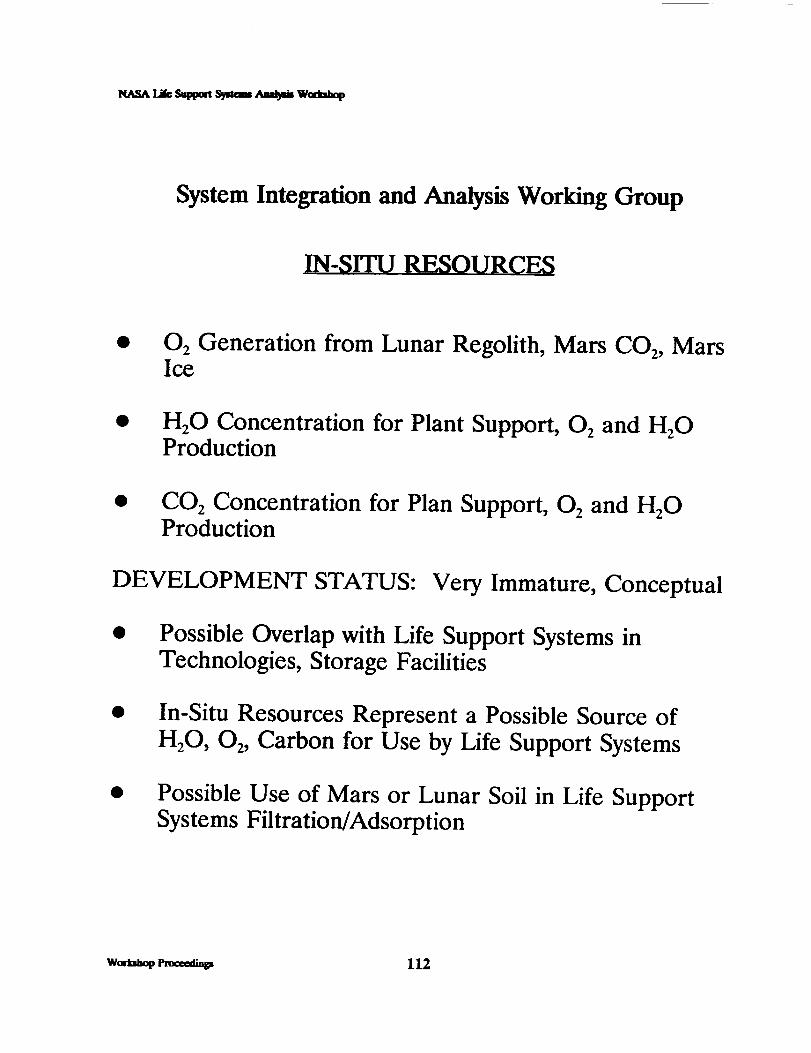
System Integration and Analysis Working Group
IN-SITU RESOURCES
0 2 Generation from Lunar Regolith, Mars CO2, MarsIce
H20 Concentration for Plant Support, 0 2 and H20
Production
CO2 Concentration for Plan Support, 0 2 and H20
Production
DEVELOPMENT STATUS: Very Immature, Conceptual
Possible Overlap with Life Support Systems inTechnologies, Storage Facilities
In-Situ Resources Represent a Possible Source ofH/O, 02, Carbon for Use by Life Support Systems
Possible Use of Mars or Lunar Soil in Life SupportSystems Filtration/Adsorption
w_ _ 112

System Integration and Analysis Working Group
LABORATORY SYSTEMS
• Waste Handling
Similar Organic Wastes, but Likely to be
Segregated from Human Wastes
Need for Odor Control - ToxicContamination Control
• Water Supply, Clean-Up Issues
_, Relation to Life Support Systems
Lab Systems will be Isolated from LifeSupport Systems to MinimizeContamination, Hence MinimalInteraction
Possibility for Use of CommonTechnologies
113 w__

NASA Li_ S_tmrt _m=_ ,'u_#* W_
System Integration and Analysis Working Group
USE OF LIFE SUPPORT SYSTEMS WASTES
Reuse of Life Support Systems Wastes• Ash
- Shielding• Waste Plastics
Waste Metals
- Remanufacture into Foils, StructuralMaterials, etc.
Spent Tanks, Resupply Units Used in LifeSupport Systems Resupply- Cut Down into Structural Materials
Excess Water From Life Support Systems- Use as Radiation Shielding
Remanufacture into New Packaging, etc.
Decompose into C, H for Use in LifeSupport Systems and ElsewhereUse as Radiation Shielding
Low Tech or Uses (Mostly) Well-DevelopedTechnologies that may need some Re-Engineeringto Minimize Generation of Toxics
Workshop Proceedings 114

System Integration and Analysis Working Group
EXTRAVEHICULAR ACYFIVI'I_ (EVA)
Environmental Control Life Support System (Suitand Vehicle) Recharge Issues
Life Support System Will Need to ResupplyEVA, and to Process Wastes from EVA
• Suit Cleaning
• Common Fluids?? Water
• Other
EVA is a Source of Possible Contaminants
(e.g., Dust) Harmful to the Life SupportSystems
115 w.a_,_p

_msALi_S_ma_tam ._,i, w, mm,,_
System Integration and Analysis Working Group
EXISTING SOFTWARE FOR MODELINGINTEGRATED SYSTEMS
• Integrated System Performance Model (ISPM)
Electrical, Thermal, Guidance, Life Support,Solar/External
• Developed for Space Station Freedom
Contact: John Tandler, Grumman (703) 438-5786
Integrated Systems Analysis Tool for SpaceExploration Initiative
Contact: Henry Woo, David Haines, Rockwell-Downey, CA
• System Design Trade-Off Model (SDTM)
• Developed for Space Station Freedom
Contact: Jeff Smith, JPL
Woft_op l't_ 116

_m._.Li_ Suppm S_:m .,uuua_ Woam_
System Integration and Analysis Working Group
RECOMMENDATIONS
NASA HQ Sponsor a Meeting of Key TechnicalStaff Involved in Power, Propulsion, Life Support,etc. Arrange Overview Briefings
Currently, Individuals Do Not UnderstandOther Systems as well as is Needed
Screen List of Possible Interactions using Analysisof Risk and Reliability Dependencies and OtherSystem Engineering Techniques
Investigate Possibilities for Common Materials,Components among systems
117 womamp Pn,ca_a_u_

THIS PAGE INTENTIONALLY LEFT BLANK
woa_,op l.m,_t_. 118

REPORT DOCUMENTATION PAGEI Form Approved
j OMB No. 0704-0188
Public report_g burden for this collectionof inIomultionis estimallrdto average 1 hourper response, includingthe time for rq_ewing instructions,searching existingdata sources,gatheringand rnaintaJnJngthe data need_l, and oomplatJng and reviewingthe collectionof Irdocmatton.Send ¢om_ retarding this burdenestimate or imy other aspect of thiscollectionof information,includingsuggestionsfor r_ucing _; burden, to WashingtonHeaOquart_s Services,Directoratetor i_xmation Operations and Reports,1215 Jethwr,onDavis Highway, Suite 1204, Arlington,VA 22202-4302, and tOthe Offmeof Management and Budget.Pal::mcworkReductionProject(0704-0188), Washington, DC 20503.
1. AGENCY USE ONLY (Leave blank) 2. REPORT DATE
1 March 1992
4. TITLE AND SUBTITLE
1991 Life Support Systems Analysis Workshop
Workshop Report
6. AUTHOR(S)
Evanich, Peggy L.; NASA Headquarters
Crabb, Thomas M.; Orbital Technologies CorporationGartrell, Charles; General Research Corporation
7. PERFORMING ORGANIZATION NAME(S) AND ADDRESS(ES)
Orbital Technologies Corporation402 Gammon Place, Suite 10Madison, Wisconsin 53719
6, SPONSORING/MONITORING AGENCY NAMES(S) AND ADDRESSIES)
Office of Aeronautics and Space Technology
National Aeronautics and Space AdministrationWashington, DC 20546
3. REPORT TYPE AND DATES COVERED
Final- 1991 Report5. FUNDING NUMBERS
Contract #NASW-4470
S. PERFORMING ORGANIZATIONREPORT NUMBER
N/A
10. SPONSORING/MONITORINGAGENCY REPORT NUMBER
NASA CR 4466
11. SUPPLEMENTARY NOTES
12s. DISTRIBUTION/AVAILABILITY STATEMENT
Unclassified - Unlimited
Subject Category 54
12b. DISTRIBUTION CODE
13. ABSTRACT (Maximum 200 words)
The 1991 Life Support Systems Analysis Workshop was sponsored by NASA Headquarters' Office of
Aeronautics and Space Technology (OAST) to foster communication among NASA, industrial, and academic
specialists, and to integrate their inputs and disseminate information to them. The overall objective of systems
analysis within the Life Support Technology Program of OAST is to identify, guide the development of, and
verify designs which will increase the performance of the life support systems on component, subsystem, and
system levels for future human space missions. The specific goals of this workshop were to report on the
status of systems analysis capabilities, to integrate the chemical processing industry technologies, and to
integrate recommendations for future technology developments related to systems analysis for life support
systems. The workshop included technical presentations, discussions, and interactive planning, with timeallocated for discussion of both technology status and time-phased technology development recommendations.
Key personnel from NASA, industry, and academia delivered inputs and presentations on the status and
priorities of current and future systems analysis methods and requirements.
4_. SUBJECT TERMS
space
life support17. SECURITY CLASSIFICATION
OF REPORT
Unclassified
modeling
s)'stems anallcsis18. SECURITY CLASSIFICATION
OF THIS PAGE
Unclassified
simulation
anal)'sis19. SECURITY CLASSIFICATION
OF ABSTRACT
Unclassified
15. NUMBER OF PAGES
llx16. PRICE CODE
AO920. LIMITATION OF ABSTRACT
Unlimited
NSN 7540-01-280-5500
PRECEDING PAGE BLANK NOT FILMED
Standard Form 298 (Rev. 2-89)
Prescribed by ANSI Std. Z39-18298-102