Embed Size (px)
Citation preview

STEERING
PRECAUTIONS ................................................... TROUBLESHOOTING ........................................... ON-VEHICLE INSPECTION ................................... STEERING COLUMN ...........................................
USA .............................................................. CANADA .......................................................
POWER STEERING .............................................. Description ..................................................... On-Vehicle Inspection ...................................... Power Steering Pump ...................................... Gear Housing ..................................................
WIO PPS (Progressive Power Steering) ........... w l PPS (Progressive Power Steering) .............
Progressive Power Steering ..............................
Page
5r-2
5r-2
5r-3
5r-4
5r-7 5r-22
5r-36
5r-36
5r-40
5r-45
5r-57
5r-6 1
5r-76
5r-90

SR-2 STEERING - Precautions, Troubleshootina
Problem
Hard steering
PRECAUTIONS Care must be taken to replace parts properly because they could affect the performance of the steering system and result in a driving hazard.
(USA) The steering wheel pad has an airbag built in, so take all due precautions when handling it. For more details, see the SRS AIRBAG section.
TROUBLESHOOTING
Poor return
Excessive play
I Possible cause
Tires improperly inflated
Excessive caster
Steering system joint worn
Ball joints worn
Steering column binding
Steering gear out of adjustment or broken
Power steering belt loose
Fluid level in reservoir low
Power steering unit faulty
Solenoid valve faulty
Electronic control faulty
Tires improperly inflated
Wheel alignment incorrect
Steering column binding
Steer~ng gear out of adjustment or broken
Front hub bearing worn
Main shaft yoke or intermediate shaft yokc
worn
Ball joints worn
Steering system joints worn
Steering gear out of adjustment or broken
Steering linkage loose
i Steering system joints worn
Steering gear out o f adjustment or broken
lnspect solenoid valve
Inspect electronic control
Remedy - -
Inflate tires to proper pressure
Check front wheel alignment
lnspect steering column
Adjust or repair steerlng gear
Page
Replace front hub bearing 1 FA-8
Inflate tlres to proper pressure FA-3
Check front wheel al~gnment I FA-3
Replace steerlng system p n t s 1 SR-57
lnspect upper and lower ball jo~nts FA-21
Inspect steerlng column SR-4
Adjust or repalr steerlng gear 1 SR-57
Adjust belt tension SR-40
Check reservoir 011 level SR-40
Check power steerlng u n ~ t SR-40
SR-94
SR-90 1 1 FA-3
FA-3
1 SR-4
Replace maln shaft or intermediate I shaft I lnspect upper and lower ball joints FA-21
Replace steerlng system jo~nts 1 SR-57
Adjust or repair steering gear SR-57
Tighten steering linkage
Replace steering system joints SR-57
Adjust or repair steering gear 1 SR-57

STEERING - On-Vehicle Inspection SR-3
USA
CANADA
ON-VEHICLE INSPECTION 1. CHECK THAT STEERING WHEEL FREEPLAY IS CORRECT
With the vehicle stopped and tires pointed straight ahead, rock the steering wheel gently back and forth wi th light finger pressure. Freeplay should not exceed the maximum limit.
Maximum play: 30 mm (1.18 in.)
If incorrect, repair.
2. CHECK STEERING LINKAGE AND GEAR HOUSING
(a) Check the steering linkage for looseness or damage.
Check that: Tie rod ends do not have excessive play. Boots are not damaged. Boots clamps are not loose.
(b) Check gear housing for grease leakage or oozing.

SR-4 STEERING - Steering Column
STEERING COLUMN REMOVAL AND INSTALLATION OF STEERING COLUMN
Remove and install the parts as shown.
Heat Insulator
Column Cover
Steering Column Assembly
(CANADA)
Combination Switch
Finish Panel
Air Duct
[kg-cm (ft-lb, N-rn) 1 : Specified torque

STEERING - Steering Column SR-5
Airbag Wire Harness ~ ~ 0 0 4 8
SST \ A60049
Connector
Airban Wire ~a';ness A60206
(MAIN POINTS OF REMOVAL AND INSTALLATION)
(USA)
CAUTION: Work must be started after approx. 20 sec- onds or longer from the time the ignition switch is turned to the LOCK position and the negative ( - ) terminal cable is disconnected from the battery (See page AB-2).
NOTICE: If the wiring connector of the airbag system is disconnected with the ignition switch at ON or ACC, di- agnostic codes will be recorded.
1. REMOVE STEERING WHEEL PAD
(a) Disconnect the battery negative ( - 1 terminal.
(b) Place the front wheels facing straight ahead.
(c) Using a torx wrench, loosen the four screws.
Torx wrench: T 3 0 (Part No.09042-00010 or locally manufactured tool)
(d) Loosen the torx screws until the groove along the screw circumference catches on the screw case.
(e l Pull the wheel pad out f rom the steering wheel and disconnect the airbag connector.
NOTICE: When removing the wheel pad, take care not t o pull the airbag wire harness.
CAUTION: When storing the wheel pad, keep the upper surface of the pad facing upward.
2. REMOVE STEERING WHEEL
(a) Disconnect the connector.
(b) Remove the set nut.
(c) Using SST, remove the steering wheel
SST 0 9 2 1 3-3 1 0 2 1
3. INSTALL STEERING WHEEL AND WHEEL PAD
(a) Check that the front wheels are facing straight ahead.
(b) Center the spiral cable. (See page AB-16)
(c) Install the steering wheel and torque the set nut.
Torque: 350 kg-cm (25 ft-lb, 3 4 N.m)
(d l Connect the connector.
SR-6 STEERING - Steering Column
(e) Install the wheel pad after confirming that the circum- ference groove of the torx screws is caught on the screw case.
( f ) Using a torx wrench, tighten the four screws.
Torque: 75 kg-cm (65 in.-lb, 7.4 N-m)
NOTICE: Make sure the wheel pad is installed to the specified torque.
If the wheel pad has been dropped, or there are cracks, dents or other defects in the case or connector, re- place the wheel pad with a new one.
When installing the wheel pad, take care that the wir- ings do not interfere with other parts and are not pinched between other parts.
4. CHECK STEERING WHEEL CENTER POINT AFTER IN- STALLING STEERING COLUMN
(CANADA)
1. REMOVE STEERING WHEEL
(a) Remove the screw at the lower portion of the steer- ing wheel pad and pull the pad out upward.
(b ) Remove the steering wheel set nut.
( c ) Using SST, remove the steering wheel.
SST 09609-2001 1
2. CHECK STEERING WHEEL CENTER POINT AFTER INSTALLING STEERING COLUMN

STEERING - Steering Column (USA) SR-7
USA COMPONENTS
(w/ AT) Support Shim Key Interlock Solenoid
Serration Bolt
Column Tube Stopper I
Telescopic Lever B O I ~
No. 2 Tilt Sub Lever Telescopic Lever
0. 1 Tilt Sub Lever
- Dust Seal
Column Tube
Intermediate Shaft
Thrust Stopper
Column Hole Cover
I kg-cm (ft-lb, N - m ) 1 : Specified torque
+ Non-reusable part SR3668

SR-8 STEERING - Steering Column (USA)
DISASSEMBLY OF STEERING COLUMN
1. (w/ TEMS) REMOVE STEERING SENSOR
Remove the t w o screws with the steering sensor.
2. REMOVE IGNITION KEY LIGHT
Remove the screw and ignition key light.
3. REMOVE COLUMN HOLE COVER
(a) Remove the t w o bolts and column hole cover.
(b) Remove the O-ring and cover plate.
4. REMOVE INTERMEDIATE SHAFT
(a) Remove the bolt from the main shaft.
(b) Remove the t w o set bolts and retainer bracket.
(c) Pull out the intermediate shaft from the column tube.
5. REMOVE COLUMN TUBE
Remove the four breakaway bracket bolts, and pull out the column tube.

STEERING - Steerina Column (USA) SR-9
6. REMOVE TENSION SPRINGS AND CORDS
(a) Fully ti lt the main shaft upward.
(b) Using a screwdriver, pry out the cord tip and remove the springs and cords.
7. REMOVE TELESCOPIC LEVER
Remove the nut and telescopic lever.
8. REMOVE TELESCOPIC LEVER LOCK BOLT
9 . REMOVE MAIN SHAFT ASSEMBLY
(a) Remove the column tube stopper
(b) Pull out the main shaft assembly and then catch the t w o lock wedges by hand.
HINT: Be careful the spline part of the main shaft does not come loose.

SR-10 STEERING - Steerina Column (USA)
REMOVE TENSION SPRING
REMOVE TlLT LEVER RETAINER
(a) Remove the t w o bolts and t w o nuts.
(b) Remove the t i l t lever retainer, collar and cushion.
REMOVE TENSION SPRING
REMOVE TlLT LEVER RETAINER
Remove the bolt, t w o nuts and t i l t lever retainer.
REMOVE SPACER AND PIN

STEERING - Steering Column (USA) SR-11
15. REMOVE TlLT STEERING ADJUSTING NUT AND PIN
16. REMOVE TlLT STEERING SUPPORT STOPPER BOLT
Remove the nut, support stopper bolt and cover.
17. REMOVE SERRATION BOLTS
Temporarily install the t w o nuts t o the t w o serration bolts end for protection, and tap out the t w o serration bolts from the upper bracket.
18. REMOVE COLUMN UPPER BRACKET
(a) Remove the column upper bracket from the breaka- w a y bracket.
(b) Remove the t w o bolts.

SR-12 STEERING - Steering Column (USA)
(c) Remove the following parts: Tilt steering No. 1 support collar Tilt lever No.1 ti lt sub lever Tilt steering No.2 support collar No.2 ti lt sub lever Support shim
(dl Using a chisel, remove the steering shaft thrust stop- per wi th the three screws.
19. REMOVE TWO STEERING PAWLS
20. REMOVE TWO SERRATION BOLTS
Temporarily install the t w o nuts to the t w o serration bolts end for protection, and tap out the serration bolts from the breakaway bracket.
21. (wl TEMS) REMOVE STEERING SENSOR DISC
(a) Using a hammer and brass bar, drive out the steering sensor disc from the intermediate shaft.
(b) Using snap ring pliers, remove the snap ring.

STEERING - Steering Column (USA) SR-13
22. REMOVE THRUST STOPPER
(a) Using snap ring pliers, remove the snap ring.
(b) Remove the thrust stopper.
(c) Remove the O-ring from the thrust stopper.
INSPECTION AND REPAIR OF STEERING COLUMN
1. INSPECT STEERING LOCK OPERATION
Check that the steering lock mechanism operates properly.
2. IF NECESSARY, REPLACE KEY CYLINDER
(a) Place the ignition key at the ACC position.
(b) Push down the stop key with a thin rod, and pull out the key cylinder.
(c) Make sure that the ignition key is at the ACC position.
(d) Install a new key cylinder.
3. (wl AT) IF NECESSARY, REPLACE KEY INTERLOCK SOLENOID
(a) Remove the t w o screws and solenoid.
(b) Install a new solenoid wi th the t w o screws.
ASSEMBLY OF STEERING COLUMN (See page SR-7)
1. COAT ALL RABBING PARTS WITH M P GREASE
2. INSTALL THRUST STOPPER
(a) Install a new O-ring to the thrust stopper.
(b) Install the thrust stopper.
(c) Using snap ring pliers, install the snap ring.

SR-14 STEERING - Steering Column (USA)
Mark SR1623
(wl TEMS) INSTALL STEERING SENSOR DISC
(a) Using snap ring pliers, install the snap ring.
(b) Using a 14 mm socket wrench, press in a new steer- ing sensor disc.
INSTALL STEERING SHAFT THRUST STOPPER
Install the steering shaft thrust stopper wi th three new screws.
INSTALL N0 .2 TILT SUB LEVER
Install the No.2 ti lt sub lever to the column upper bracket.
SELECT N 0 . 2 SUPPORT COLLAR
Select a No.2 collar which will eliminate all play.
diameter rnrn (in.)
17.989 - 17.996 (0.7082 - 0.7085)
17.996 - 18.003 (0.7085 - 0.7088)
18.003 - 18.010 (0.7088 - 0.7091)
18.010 - 18.017 (0.7091 - 0.7093)

STEERING - Steering Column (USA) SR-15
7 . INSTALL TlLT LEVER
Install the t i l t lever t o the column upper bracket.
8. SELECT NO. l SUPPORT COLLAR
Select a No.1 collar which wil l eliminate all play.
Outer diameter rnm (in.) I
9. INSTALL TWO SERRATION BOLTS AND TWO TlLT PAWLS
(a) Install the t w o serration bolts t o the breakaway bracket.
(b) Install the t w o pawls and one of the bushing wi th cutout portion.
10. INSTALL COLUMN UPPER BRACKET
(a) Wi th the column upper bracket partially installed t o the breakaway bracket, move the pawl toward the column upper bracket side and then completely install the column upper bracket.
(b) Insert the serration bolt of No.1 support collar side.

SR-16 STEERING - Steering Column (USA)
11. INSTALL SUPPORT STOPPER BOLT
Install the cover to the bolt, and align the cutout portion of the support stopper bolt and upper bracket, install it from inside of the column upper bracket.
Torque: 1 10 kg-crn (8 ft-lb, 1 1 Nmrn)
12. INSTALL NO. l TlLT SUB LEVER
Insert the tilt lever pin into the hole of the No. 1 tilt sub lever.
13. INSTALL SPACER AND PIN
14. INSTALL TlLT LEVER RETAINER
(a) Install the tilt lever retainer with the collar, cushion and bolt.
Torque: 195 kg-crn (14 ft-lb, 19 Nmm)
(b) Temporarily install the two nuts and washers.
(c) Hold the serration bolt and tighten the two nuts.
Torque: 195 kg-crn (14 ft-lb, 19 N-rn)
(dl Install and torque the bolt.
Torque: 8 0 kg-cm (69 in.-lb, 7 .8 N-m)

STEERING - Steering Column (USA) SR-17
15. SELECT SUPPORT SHIM
Select one or t w o shims which f i t snugly when pressed in by hand.
16. INSTALL SERRATION BOLT, TlLT STEERING ADJUSTING NUT AND PIN
Mark
None
5
8
14
18
17. INSTALL TlLT LEVER RETAINER
(a) Install the ti lt lever retainer.
(b) Install the t w o nuts and washers.
(c) Holding the serration bolts and tighten the nuts.
Torque: 195 kg-cm (14 ft-lb, 19 Nnm)
Thickness mm (in.)
0.197 - 0.203 (0.0078 - 0.0080)
0.495 - 0.505 (0.01 95 - 0.01 99)
0.795 - 0.805 (0.0313 - 0.0317)
1.395 - 1.405 (0.0549 - 0.0553)
1.795 - 1.805 (0.0707 - 0.07 1 1 )
18. ADJUST ENGAGEMENT OF N0 .2 TlLT SUB LEVER
(a) Pulling the No.2 tilt sub lever, disengage the pawl from the column upper bracket.
(b) Moving the column upper bracket up or down, engage the opposite pawl wi th the column upper bracket.
(c) Loosen the nut until the tilt steering adjusting nut turns smoothly.
SR-18 STEERING - Steering Column (USA)
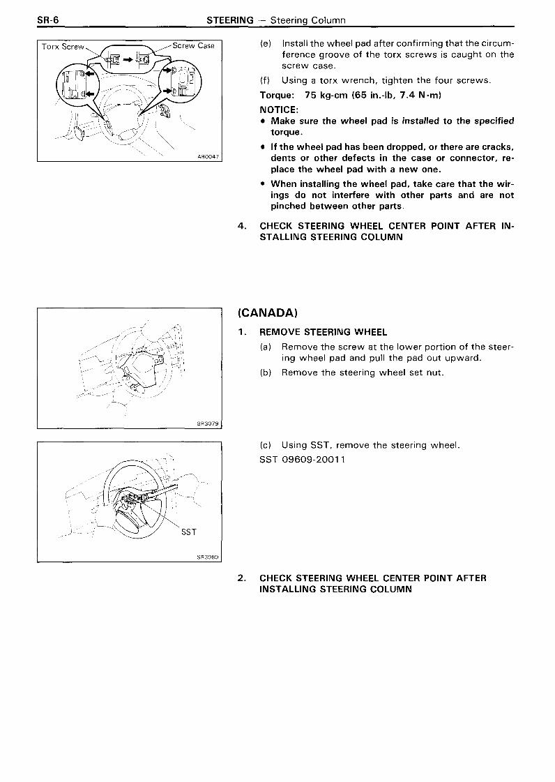
(dl Pushing the pawl toward the column upper bracket, engage the pawl with the upper bracket by moving the adjusting nut.
(e) Tighten the nut and bolt as in figure and tighten the right and left bolts of the tilt lever.
Torque: Nut 195 kg-cm (14 ft-lb, 19 N-m) Bolt 8 0 kg-cm (69 in.-lb, 7.8 N-m)
19. INSTALL TWO TENSION SPRINGS
20. INSTALL MAIN SHAFT ASSEMBLY
(a) Install the two lock wedges to the column upper bracket.

STEERING - Steering Column (USA) SR- 19
(b) Mark the main shaft as shown.
(c) Place the ignition key at the ACC position.
(d) Insert the main shaft assembly into the upper bracket.
(el Install the column tube stopper.
Torque: 80 kg-cm (69 in.-lb, 7.8 N-m)
INSTALL TELESCOPIC LEVER LOCK BOLT
Tighten the telescopic lever lock bolt wi th the telescopic lever.
HINT: The bolt has LH threads.
INSTALL TELESCOPIC LEVER
(a) Install the telescopic lever so it parallels the main shaft.
(b) Tighten the set nut.
Torque: 145 kg-cm (10 ft-lb, 14 N - m )

SR-20 STEERING - Steering Column (USA)
23. INSTALL TENSION SPRINGS AND CORDS
(a) Fully tilt the main shaft upward.
(b) Connect the spring and cord, and hook the spring to the hanger.
(c) Using a screwdriver, hook the cord end to the column upper bracket.
24. INSTALL COLUMN TUBE TO BREAKAWAY BRACKET
(a) Install the column tube to the breakaway bracket.
(b) Place the bond cable.
(c) Install and torque the four bolts.
Torque: 195 kg-cm (14 ft-lb, 19 N-m)
25. INSTALL INTERMEDIATE SHAFT TO COLUMN TUBE
(a) Coat the O-ring of the thrust stopper with MP grease.
(b) Install the intermediate shaft to the column tube.
(c) Connect the universal joint of main shaft and inter- mediate shaft.
Torque: 260 kg-cm (19 ft-lb, 25 N.m)
(d) Match the mark on the shaft accords with the upper bracket surface. as shown.
(e) Install the retainer bracket and two bolts.
( f ) Torque the two bolts.
Torque: 280 kg-cm (20 ft-lb, 27 N -m)


SR-22 STEERING - Steering Column (CANADA)
CANADA COMPONENTS
Support Shlm
No. 2 Tilt Sub L Telescop~c Lever
etalner A Column Tube
Thrust Stopper
Cover Plate --
+ 0 - R ~ n g
I kg-cm (ft-lb, N-m) 1 : Specified torque
+ Non-reusable part SR3669

STEERING - Steering Column (CANADA) SR-23
DISASSEMBLY OF STEERING COLUMN
1. REMOVE IGNITION KEY LIGHT
Remove the screw and ignition key light.
2. REMOVE COLUMN HOLE COVER
( a ) Remove the t w o bolts and column hole cover.
(b) Remove the O-ring and cover plate.
3. REMOVE INTERMEDIATE SHAFT
(a) Remove the bolt from the main shaft.
(b) Remove the t w o set bolts and retainer bracket.
(c) Pull out the intermediate shaft from the column tube.
/ 1 4. REMOVE COLUMN TUBE Remove the four breakaway bracket bolts, and pull out the column tube.

SR-24 STEERING - Steering Column (CANADA)
5 . REMOVE TENSION SPRINGS AND CORDS
(a) Fully tilt the main shaft upward.
(b) Using a screwdriver, pry out the cord tip and remove the springs and cords.
6. REMOVE TELESCOPIC LEVER
Remove the nut and telescopic lever.
7. REMOVE TELESCOPIC LEVER LOCK BOLT
8. REMOVE MAIN SHAFT ASSEMBLY
(a) Remove the column tube stopper.
(b) Pull out the main shaft assembly and then catch the two lock wedges by hand.
HINT: Be careful the spline part of the main shaft does not come loose.

STEERING - Steering Column (CANADA) SR-25
9. REMOVE TWO TENSION SPRINGS
10. REMOVE TlLT LEVER RETAINER
(a) Remove the bolt and t w o nuts.
(b) Remove the tilt lever retainer, collar and cushion
1 1. REMOVE TENSION SPRING
12. REMOVE TlLT LEVER RETAINER
Remove the t w o nuts and tilt lever retainer.
13. REMOVE SPACER AND PIN

SR-26 STEERING - Steering Column (CANADA)
14. REMOVE TlLT STEERING ADJUSTING NUT AND PIN
15. REMOVE TlLT STEERING SUPPORT STOPPER BOLT
Remove the nut, support stopper bolt and cover.
16. REMOVE SERRATION BOLTS
Temporarily install the t w o nuts t o the t w o serration bolts end for protection, and tap out the t w o serration bolts from the upper bracket.
17. REMOVE COLUMN UPPER BRACKET
(a) Remove the column upper bracket f rom the breaka- way bracket.
(b) Remove the t w o bolts.

STEERING - Steering Column (CANADA) SR-27
(c) Remove the following parts: Tilt steering No. 1 support collar Tilt-up control lever Tilt adjust lever No. 1 ti lt sub lever Adjuster memory cover Tilt steering No.2 support collar No.2 ti lt sub lever Support shim
(d) Using a chisel, remove the steering shaft thrust stop- per with the three screws.
18. REMOVE TWO STEERING PAWLS
19. REMOVE TWO SERRATION BOLTS
Temporarily install the t w o nuts to the t w o serration bolts end for protection, and tap out the serration bolts from the breakaway bracket.
20. REMOVE THRUST STOPPER
(a) Using snap ring pliers, remove the snap ring
(b) Remove the thrust stopper.
( c ) Remove the O-ring from the thrust stopper.

SR-28 STEERING - Steering Column (CANADA)
INSPECTION AND REPAIR OF STEERING COLUMN
1. INSPECT STEERING LOCK OPERATION
Check that the steering lock mechanism operates properly.
2. IF NECESSARY, REPLACE KEY CYLINDER
(a) Place the ignition key at the ACC position.
(b) Push down the stop key with a thin rod, and pull out the key cylinder.
(c) Make sure that the ignition key is at the ACC position.
(d l lnstall a new key cylinder.
3. (wl AT) IF NECESSARY, REPLACE KEY INTERLOCK SOLENOID
(a) Remove the t w o screws and solenoid.
(b) lnstall a new solenoid with the t w o screws.
ASSEMBLY OF STEERING COLUMN (See page SR-22)
1. COAT ALL RABBING PARTS WITH M P GREASE
2 . INSTALL THRUST STOPPER
(a) lnstall a new O-ring to the thrust stopper.
(b) lnstall the thrust stopper.
(c) Using snap ring pliers, install the snap ring.
3. INSTALL STEERING SHAFT THRUST STOPPER
lnstall the steering shaft thrust stopper wi th three new screws.

STEERING - Steering Column (CANADA) SR-29
4. INSTALL N 0 . 2 TlLT SUB LEVER
Install the No.2 ti lt sub lever to the column upper bracket.
5. SELECT N0.2 SUPPORT COLLAR
Select a No.2 collar which will eliminate all play.
I Outer diameter mm (in.) I
6. INSTALL ADJUSTER MEMORY COVER
Install the adjuster memory cover to the ratchet of the column upper bracket.
7. INSTALL TILT-UP CONTROL LEVER AND NO. l TlLT SUB LEVER
(a) Assemble the No. 1 ti lt sub lever to the tilt-up control lever.
(b) Install the tilt-up control lever to the column upper bracket.

SR-30 STEERING - Steering Column (CANADA)
8. INSTALL TlLT ADJUST LEVER
(a) Align the t i l t adjust lever hole t o the adjuster memory cover pin.
(b) Assemble the ti lt adjust lever between the tilt-up con- trol lever and No. I ti l t sub lever.
9. SELECT NO. l SUPPORT COLLAR
Select a No.1 collar which will eliminate all play.
I Outer diameter mln (in.)
10. INSTALL TWO SERRATION BOLTS AND TWO TlLT PAWLS
(a) Install the t w o serration bolts t o the breakaway bracket.
(b) Install the t w o pawls and one of the bushing wi th cutout portion.
1 1. INSTALL COLUMN UPPER BRACKET
(a) Wi th the column upper bracket partially installed t o the breakaway bracket, move the pawl toward the column upper bracket side and then completely install the column upper bracket.
(b) Insert the serration bolt of No. I support collar side.
STEERING - Steering Column (CANADA) SR-31
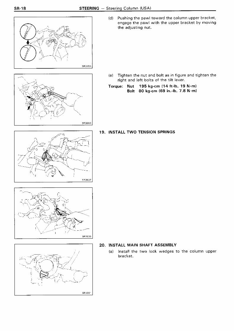
12. INSTALL SUPPORT STOPPER BOLT
Install the cover to the bolt, and align the cutout portion of the support stopper bolt and upper bracket, install it from inside of the column upper bracket.
Torque: 1 10 kg-cm (8 ft-lb, 1 1 N-m)
13. INSTALL SPACER AND PIN
14. INSTALL TILT LEVER RETAINER
(a) Install the ti lt lever retainer wi th the collar, cushion and bolt.
Torque: 195 kg-cm (14 ft-lb, 19 N.m)
(b) Temporarily install the t w o nuts and washers.
(c) Hold the serration bolt and tighten the t w o nuts.
Torque: 195 kg-cm (14 ft-lb, 19 Nmm)
15. SELECT SUPPORT SHIM
Select one or t w o shims which f i t snugly when pressed in by hand.
Mark Thickness mrn (in.)
None
5
8
1 4
18
0.1 97 - 0.203 (0.0078 - 0.0080)
0.495 - 0.505 (0.01 95 - 0.01 99)
0.795 - 0.805 (0.031 3 - 0.031 7)
1.395 - 1.405 (0.0549 - 0.0553)
1.795 - 1.805 (0.0707 - 0.071 1)

SR-32 STEERING - Steering Column (CANADA)
16. INSTALL SERRATION BOLT, TlLT STEERING ADJUSTING NUT AND PIN
17. INSTALL TlLT LEVER RETAINER
(a) Install the tilt lever retainer.
(b) Install the two nuts and washers.
(c) Holding the serration bolts and tighten the nuts.
Torque: 195 kg-cm (1 4 ft-lb, 19 N-ml
18. ADJUST ENGAGEMENT OF N 0 . 2 TlLT SUB LEVER
(a) Pulling the No.2 tilt sub lever, disengage the pawl from the column upper bracket.
(b) Moving the column upper bracket up or down, engage the opposite pawl with the column upper bracket.
(c) Loosen the nut until the tilt steering adjusting nut turns smoothly.
(d) Pushing the pawl toward the column upper bracket, engage the pawl with the upper bracket by moving the adjusting nut.

STEERING - Steering Column (CANADA) SR-33
(el Tighten the nut as in figure and tighten the right and left bolts of the ti lt lever.
Torque: Nut 195 kg-cm (14 ft-lb, 19 N-m) Bolt 80 kg-cm (69 in.-lb, 7.8 Nnm)
19. INSTALL TENSION SPRING
20. INSTALL TWO TENSION SPRINGS
1 21. INSTALL MAIN SHAFT ASSEMBLY
25.5 mm ( 1 .OO4 in.)
--t t-
) Mark
(a) Install the t w o lock wedges to the column upper bracket.
(b) Mark the main shaft as shown,

SR-34 STEERING - Steering Column (CANADA)
(c) Place the ignition key at the ACC position.
(d l Insert the main shaft assembly into the upper bracket.
(e) Install the column tube stopper.
Torque: 8 0 kg-cm (69 in.-lb, 7.8 N - m )
22. INSTALL TELESCOPIC LEVER LOCK BOLT
Tighten the telescopic lever lock bolt wi th the telescopic lever.
HINT: The bolt has LH threads.
23. INSTALL TELESCOPIC LEVER
(a) Install the telescopic lever so it parallels the main shaft.
(b) Tighten the set nut.
Torque: 1 4 5 kg-cm (10 ft-lb, 1 4 N - m )
24. INSTALL TENSION SPRINGS AND CORDS
(a) Fully ti lt the main shaft upward.
(b) Connect the spring and cord, and hook the spring to the hanger.
(c) Using a screwdriver, hook the cord end to the column upper bracket.

STEERING - Steering Column (CANADA) SR-35
25. INSTALL COLUMN TUBE TO BREAKAWAY BRACKET
(a) Install the column tube t o the breakaway bracket
(b) Place the bond cable.
(c) lnstall and torque the four bolts.
Torque: 195 kg-cm (14 ft-lb, 19 N.ml
26. INSTALL INTERMEDIATE SHAFT TO COLUMN TUBE
(a) Coat the O-ring o f the thrust stopper w i th MP grease.
(b) Install the intermediate shaft t o the column tube.
(c) Connect the universal joint of main shaft and inter- mediate shaft.
Torque: 260 kg-cm (19 ft-lb, 25 N-m)
(d l Match the mark on the shaft accords w i th the upper bracket surface, as shown.
(e) Install the retainer bracket and t w o bolts.
( f ) Torque the t w o bolts.
Torque: 280 kg-cm (20 ft-lb, 27 N.m)
27. INSTALL COLUMN HOLE COVER
(a) Install a new O-ring and cover plate t o the column tube.
(b) Align the cutout portion of the column tube to the pro- trusion o f the hole cover, and install w i th the t w o bolts.
Torque: 130 kg-cm (9 ft-lb, 13 Nmm)
28. INSTALL IGNITION KEY LIGHT WITH SCREW

SR-36 STEERING - Power Steering (Description)
POWER STEERING Description PRINCIPLES OF POWER STEERING
Power steering is one type of hydraulic device for utilizing engine power to reduce steering effort. Consequently, the engine is used to drive a pump to develop fluid pressure, and this pressure acts on a piston within the power cylinder so that the piston assists the rack effort. The amount of this as- sistance depends on the extent of pressure acting on the piston. Therefore, if more steering force is required, the pressure must be raised. The varia- tion in the fluid pressure is accomplished by a con- trol valve which is linked to the intermediate shaft and the steering main shaft.
NEUTRAL (STRAIGHT-AHEAD) POSITION
Fluid from the pump is sent to the control valve. If the control valve is in the neutral position, all the fluid will f low through the control valve into the relief port and back to the pump. At this time, hardly any pressure is created and because the pressure on the cylinder piston is equal on both sides, the piston will not move in either direction.
WHEN TURNING
When the steering main shaft is turned in either direction, the control valve also moves, closing one of the fluid passages. The other passage then opens wider, causing a change in fluid f low volume and, at the same time, pressure is created. Consequent- ly, a pressure difference occurs between both sides of the piston and the piston moves in the direction of the lower pressure so that the fluid in the cylinder is forced back to the pump through the control valve.
Reservoir Tank
Contr Valve
Gear Housing
Power cylinder Cylinder Piston SR2390

STEERING - Power Steering (Description) SR-37
SERVICE HINT
Troubles wi th the power steering system are usually concerned w i th hard steering due t o the fact that there is no assist. In such cases, before attempt- ing t o make repairs, i t is necessary t o determine whether the trouble lies w i th the pump or w i th the gear housing. To do this, an on-vehicle inspection can be made by using a pressure gauge.
ON-VEHICLE INSPECTION
Power steering is a hydraulic device and problems are normally due t o insufficient fluid pressure act- ing on the piston. This could be caused by either the pump not producing the specified fluid pressure or the control valve in the gear housing no t func- tioning properly so that the proper fluid pressure can not be obtained.
If the fault lies w i th the pump, the same symptoms will generally occur whether the steering wheel is turned fully t o the right or left . On the other hand, if the fault lies w i th the control valve, there wil l generally be a difference between the amount o f assist when the steering wheel is turned t o the left and right, causing harder steering. However, if the piston seal of the power cylinder is worn, there will be a loss of fluid pressure whether the steering wheel is turned t o the right or left and the symptoms wil l be the same for both.
Before performing an on-vehicle inspection, a check must first be made t o confirm that the power steer- ing system is completely free o f any air. If there is any air in the system, the volume o f this air wil l change when the fluid pressure is raised, causing a fluctuation in the fluid pressure so that the pow- er steering will no t function properly. To determine if there is any air in the system, check t o see if there is a change of fluid level in the reservoir tank when the steering wheel is turned fully t o the right or left.
For example, if there is air in the system, i t wi l l be compressed t o a smaller volume when the steer- ing wheel is turned, causing a considerable drop in the fluid level. If the system is free o f air, there wil l be very little change in the level even when the fluid pressure is raised. This is because the fluid, being a liquid, does not change volume when com- pressed. The litt le change in the fluid level is due t o expansion of the hoses between the pump and gear housing when pressure rises.
When Turning
S R 2 3 9 2
Neutral
S R 2 3 9 3
Also, air in the system wil l sometimes result in an abnormal noise occuring f rom the pump or gear housing when the steering wheel is fully turned in either direction.
This on-vehicle inspection must be performed ev- ery t ime t o ensure that the power steering system is working properly after overhauling or repairing the pump or gear housing.
VANE PUMP
The main component parts of the vane pump, such as the cam ring, rotor, vane plates and f l ow con- trol valve are high precision parts and must be han- dled carefully. Also, because this pump produces a very high fluid pressure, O-rings are used for seal- ing each part. When reassembling the pump, al- ways use new O-rings.
In the f l ow control valve, there is a relief valve which controls the maximum pressure of the pump. The amount of this maximum pressure is very im- portant; if i t is too low, there will be insufficient power steering assist and if too high, i t wi l l have an adverse effect on the pressure hoses, oil seals, etc.. If the maximum pressure is either too high or too l ow due t o a faulty relief valve, do not disas- semble or adjust the relief valve, but replace the f l ow control valve as an assembly.

SR-38 STEERING - Power Steering (Description)
The clearance between the f low control valve and pump body installation hole is very important. After manufacture, the factory measures the size of the installation hole and outer circumference of the flow control valve, and punches a mark accord- ingly. Therefore, when replacing the f low control valve, be sure to do so wi th one having the same mark in order to insure the proper clearance.
GEAR HOUSING
If the gear housing is secured directly in a vise dur- ing overhaul, there is danger of deforming it, so al- ways first secure it in the SST provided (rack and pinion steering rack housing stand) before placing i t in the vise.
The functional parts of the pump which produce fluid pressure are the cam ring, rotor and vane plates, and these should be checked for wear. If the clearance between each is not within standard when reassembling, any worn parts should be replaced.
In this case, the replaced cam ring and rotor should be of the same length (have the same mark), and the vane plates should be replaced with those hav- ing a length corresponding to that mark, otherwise the proper thrust clearance cannot be obtained. If there is too much thrust clearance, there will be in- sufficient fluid pressure at low speeds. If there is too little thrust clearance, i t may result in seizure of the vane plates.
Inscribed Mark
The oil seals on both sides of the power cylinder are for the prevention of leakage of the high pres- sure fluid which acts on the piston. Always use new oil seals when reassembling and be very careful not to scratch or damage them.
Because of the high pressure, even the slightest scratch will cause fluid leakage, resulting in an in- operative power steering system.
Also, be very careful not to scratch the sliding por- tion of the rack which makes contact wi th the oil seals. When removing the rack ends from the rack, it is very easy to cause a burr when holding the tip of the rack with a wrench. Therefore, before as- sembling the rack, first check the tip for burrs and remove any with an oil stone.
Teflon rings are used for the piston and control valve. These teflon rings are highly durable against wear, but if it is necessary to replace them, be care- ful not to stretch the new ones. After installing a teflon ring into its groove, snug i t down into the groove before assembly of the cylinder or housing to prevent possible damage.
Teflon Ring
I
Control Valve Shaft SR2400

STEERING - Power Steering (Description) SR-39
As w i th the rack and pinion type steering, preload is very important. If the preload is not correct, i t could result in such trouble as steering wheel play or shimmy or lack of durability, so always make sure that it is correct.
PPS (Progressive Power Steering)
In addition t o the power steering functions, the PPS controls hydraulic pressure acting on the hydraul- ic reaction chamber located in the control valve of the gear box t o change steering characteristics ac- cording t o the vehicle speed.
As a result, the wheels can be turned more lightly at low speeds or when steering during the vehicle stopped, while a responsive steering feeling is as- sured at medium t o high speeds.
Vehicle Speed Sensor I - -- - -
Power Steer~ng /
Steer~ng Gear Housing
Bar
~tary Valve
Hydraulic Reaction Chamber
IDLE-UP DEVICE
The pump produces the maximum fluid pressure when the steering wheel is turned fully t o the right or left and, at this time, there is a maximum load on the pump which causes a decrease in engine idle rpm. To solve this problem, vehicles are equipped w i t h an idle-up device wh ich acts t o raise the en- gine idle rpm whenever there is a heavy load on the pump.
On EFI engines, when the piston of the air control valve is pushed by fluid pressure, the air valve opens and the volume of air by-passing the throttle valve is increased t o regulate engine rpm.
Air Flow Meter
i rl Surge Tank
Steering Gear Housing
Valve
The idle-up device functions t o raise engine idle rpm when pump fluid pressure acts on the air control valve, installed t o the pump body, t o control the f low o f air.

SR-40 STEERING - Power Steering (On-Vehicle Inspection)
Nippondenso n
Borroughs
On-Vehicle Inspection CHECK DRIVE BELT TENSION
Using a belt tension gauge, check the drive belt tension.
Belt tension gauge: Nippondenso BTG-20 (95506-00020) or Borroughs No.BT-33-73F
Drive belt tension: New belt 160 + 2 0 Ib Used belt 100 + 20 Ib
HINT: "New belt" refers to a belt which has been less than 5 minutes on a running engine. "Used belt" refers to a belt which has been used on a running engine for 5 minutes or more. After installing the drive belt, check that i t f its properly in the ribbed grooves.
FLUID LEVEL CHECK
KEEP VEHICLE LEVEL
BOOST FLUID TEMPERATURE
With the engine idling at 1,000 rpm or less, turn the steer- ing wheel from lock to lock several times to boost fluid tem- perature.
Fluid temperature: 80°C (1 76OF)
CHECK FOR FOAMING OR EMULSIFICATION
HINT: Foaming and emulsification indicate either the ex- istence of air in the system or that the fluid level is too low.
CHECK FLUID LEVEL IN RESERVOIR
Check the fluid level and add fluid if necessary.
Fluid: ATF DEXRONB I1
HINT: Check that the fluid level is within the HOT LEVEL of the tank. If the fluid is cold, check that it is within the COLD LEVEL of the tank.
CHECK IDLE-UP
1. WARM UP ENGINE
2. TURN AIR CONDITIONER SWITCH OFF
3 . CHECK IDLE-UP
(a) Fully turn the steering wheel.
(b) Check that the engine rpm decreases when the air control valve hose is pinched.
(c) Check that the engine rpm increases when the air control valve hose is released.

STEERING - Power Steering (On-Vehicle Inspection) SR-41
REPLACEMENT OF POWER STEERING FLUlD
1. JACK UP FRONT OF VEHICLE AND SUPPORT IT WlTH STANDS
2. REMOVE FLUlD RETURN HOSE FROM RESERVOIR TANK AND DRAIN FLUlD INTO CONTAINER
3. WlTH ENGINE IDLING, TURN STEERING WHEEL FROM LOCK TO LOCK WHILE DRAINING FLUlD
4. STOP ENGINE
5 . FILL RESERVOIR TANK WlTH FRESH FLUlD
Fluid type: ATF DEXRON" I1
6 . START ENGINE AND RUN IT AT 1,000 RPM
After 1 or 2 seconds, fluid wi l l begin t o discharge f rom the return hose. Stop the engine immediately a t this time.
NOTICE: Take care that some fluid remains left in the reservoir tank.
7. REPEAT STEPS 5 AND 6 FOUR OR FIVE TIMES UNTIL THERE IS NO MORE AIR IN FLUlD
8. CONNECT RETURN HOSE TO RESERVOIR TANK
9. BLEED POWER STEERING SYSTEM

SR-42 STEERING - Power Steering (On-Vehicle Inspection)
BLEEDING OF POWER STEERING SYSTEM
1. CHECK FLUID LEVEL IN RESERVOIR TANK
Check the fluid level and add fluid if necessary.
Fluid: ATF DEXRON" I1
HINT: Check that the fluid level is within the HOT LEVEL of the tank. If the fluid is cold, check that i t is within the COLD LEVEL of the tank.
2. START ENGINE AND TURN STEERING WHEEL FROM LOCK TO LOCK THREE OR FOUR TIMES
With the engine speed below 1,000 rpm, turn the steer- ing wheel to left or right full lock and keep i t there for 2 - 3 seconds, then turn the wheel to the reverse full lock and keep i t there for 2 - 3 seconds.
3. CHECK THAT FLUID IN RESERVOIR IS NOT FOAMY OR CLOUDY AND DOES NOT RISE OVER MAXIMUM WHEN ENGINE IS STOPPED
Measure the fluid level wi th the engine running. Stop the engine and measure the fluid level.
Maximum rise: 5 mm (0.20 in.)
If a problem is found, repeat steps 7 and 8. Repair the PS if the problem persists.

STEERING - Power Steering (On-Vehicle Inspection) SR-43
OIL PRESSURE CHECK
CONNECT PRESSURE GAUGE
(a) Disconnect the pressure line from the PS pump.
(b) Connect the gauge side of the pressure gauge t o the PS pump and the valve side t o the pressure line.
(c) Bleed the system. Start the engine and turn the steer- ing wheel from lock t o lock t w o or three times.
(d) Check that the fluid level is correct.
CHECK THAT FLUID TEMPERATURE IS AT LEAST 80°C (176OF)
START ENGINE AND RUN IT AT IDLE
CHECK FLUID PRESSURE READING WITH VALVE CLOSED
Close the pressure gauge valve and observe the reading on the gauge.
Minimum pressure: 75 kglcm2 (1,067 psi, 7,355 kPa)
NOTICE: Do not keep the valve closed for more than 10 seconds.
Do not let the fluid temperature become too high.
If pressure is low, repair or replace the PS pump.
OPEN VALVE FULLY
CHECK AND RECORD PRESSURE READING AT 1,000 RPM
CHECK AND RECORD PRESSURE READING AT 3,000 RPM
Check that there is 5 kg/cm2 (71 psi, 490 kPa) or less difference in pressure between the 1,000 rpm and 3,000 rpm checks.
If the difference is excessive, repair or replace the f low con- trol valve of the PS pump.

SR-44 STEERING - Power Steering (On-Vehicle Inspection)
USA
CANADA
8. CHECK PRESSURE READING WITH STEERING WHEEL TURNED TO FULL LOCK
Be sure the pressure gauge valve is fully opened and the engine idling.
Minimum pressure: 75 kglcm2 (1,067 psi, 7,355 kPa)
NOTICE: Do not maintain lock position for more than 10 seconds.
Do not let the fluid temperature become too high.
If pressure is low, the gear housing has an internal leak and must be repaired or replaced.
9. MEASURE STEERING EFFORT
(USA)
(a) Center the steering wheel and run the engine at idle.
(b) Using a spring balance, measure the steering effort in both directions.
Maximum steering effort: wlo PPS 4.7 kg (10.36 Ib, 46 Nl w l PPS 2.7 kg (5.95 Ib, 26 N)
If steering effort is excessive, repair the power steering unit.
HINT: Be sure to consider the tire type, pressure and con- tact surface before making your diagnosis.
(CANADA)
(a) Center the steering wheel and run the engine at idle.
(b) Using a torque meter, measure the steering effort in both directions.
Maximum steering effort: W/O PPS 70 kg-cm (61 in.-lb, 6.9 Nmm) w l PPS 40 kg-cm (34 in.-lb, 3.9 N-m)
If steering effort is excessive, repair the power steering unit.
HINT: Be sure to consider tire type, pressure and contact surface before making your diagnosis.
10. (w1 PPS) MEASURE STEERING EFFORT
(a) Disconnect the solenoid connector.
(b) Using a spring balance or torque meter, measure the steering effort in both directions.
(Reference) Maximum steering effort:
USA 5.7 kg (12.57 Ib, 56 N) CANADA 85 kg-cm (74 in.-lb, 8.3 Nmm)
If steering effort is not heavier, check the solenoid.
HINT: Be sure to consider the tire type, pressure and con- tact surface before making your diagnosis.

STEERING - Power Steering (Power Steering Pump) SR-45
Power Steering Pump REMOVAL AND INSTALLATION OF POWER STEERING PUMP (7M-GE Engine)
Remove and install the parts as shown.
Engine Under Cover
I kg-cm (ft-lb, N - m ) 1 : Specified torque
+ Non-reusable part
(MAIN POINTS OF REMOVAL AND INSTALLATION) 1. REMOVE DRIVE BELT AND PULLEY
Using SST, to hold the pulley, loosen the pulley set nut.
SST 09278-5401 2
2. ADJUST DRIVE BELT TENSION AFTER INSTALLING PS PUMP (See page SR-40) \ S S T
SR1492 3. BLEED POWER STEERING SYSTEM
(See page SR-42)

SR-46 STEERING - Power Steering (Power Steering Pump)
REMOVAL AND INSTALLATION OF POWER STEERING PUMP (7M-GTE Engine)
Remove and install the parts as shown.
No. land No.2 Air Hose Reservoir Tank W/ No. 4 Air Cleaner Pipe w/ Bracket
190 (14, 19) 1
375 (27, 37) 1
No. 7 Air Cleaner Hose Dr~ve Belt , * . 7 . ..
Engine Under Cover
I kg-cm (ft-lb, N - m ) ] Specified
+ Non-reusable part
(MAIN POINTS OF REMOVAL AND INSTALLATION)
1. REMOVE POWER STEERING PUMP PULLEY
(a) Using SST, hold the pulley, and loosen the nut until it can be turn by hand.
SST 09278-5401 2
(b) Loosen the PS pump set bolt until it can be turn by hand.
(c) Remove the drive belt, pulley installation nut, pulley and woodruff key.
STEERING - Power Steering (Power Steering Pump) SR-47
2. ADJUST DRIVE BELT TENSION AFTER INSTALLING PS PUMP (See page SR-40)
3. BLEED POWER STEERING SYSTEM (See page SR-42)

SR-48 STEERING - Power Steerina (Power Steerina P u m ~ )
COMPONENTS
+Oil S'eal 1 Front I Front Housing +0-Ring
Snap Ring kg-cm (ft-lb, N - m ) ] : Specified torque
+ Non-reusable part
I
+0-Ring
? Plate
Rotor Cam Ring +O-Ring
1 Rear Side Plate Vane Plate
DISASSEMBLY OF POWER STEERING PUMP
1. MOUNT PS PUMP IN VISE
2. REMOVE ADJUST STAY
Remove the t w o bolts and s tay.
3. REMOVE AIR CONTROL VALVE
4. REMOVE SUCTION PORT UNION
Remove the t w o bolts and pull out the union wi th a O-ring.

STEERING - Power Steering (Power Steering Pump) SR-49
REMOVE FLOW CONTROL VALVE AND SPRING
Remove the pressure port union, and remove the valve and spring.
REMOVE FLOW CONTROL SPRING SEAT
(a) Using snap ring pliers, remove the snap ring.
(b) Temporarily install a bolt and pull out the seat.
REMOVE REAR HOUSING
(a) Place matchmarks on the front and rear housings.
(b) Remove the four bolts and rear housing.
REMOVE REAR SIDE PLATE
(a) Using a plastic hammer, tap the rotor shaft.
(b) Remove the rear side plate.
(c) Remove the three O-rings.

SR-50 STEERING - Power Steering (Power Steering Pump)
9. REMOVE ROTOR SHAFT WITH VANE PLATES, CAM RING AND ROTOR
(a) Using a plastic hammer, tap out the rotor shaft as- sembly.
NOTICE: Be careful not to scratch the parts.
(b) Remove the wave washer.
10. DISASSEMBLE ROTOR SHAFT ASSEMBLY
(a) Remove the cam ring and vane plates.
(b) Using snap ring pliers, remove the snap ring.
(c) Remove the rotor and plate from the rotor shaft.
NOTICE: Be careful not to scratch the rotor.

STEERING - Power Steering (Power Steering Pump) SR-5 1
Thickness
Height -..
Length
l nscri bed Mark
Compressed Air
INSPECTION AND REPAIR OF POWER STEERING PUMP
INSPECT OIL CLEARANCE BETWEEN ROTOR SHAFT AND BUSHING
Using a micrometer and calipers, measure the oil clearance.
Standard clearance: 0.01 - 0.03 m m (0.0004 - 0.0012 in.)
Maximum clearance: 0.07 m m (0.0028 in.)
If the clearance is greater than maximum, replace the en- tire PS pump.
INSPECT ROTOR AND VANE PLATES
(a) Using a micrometer, measure the height, thickness and length of the vane plates.
Minimum height: 8.1 mm (0.319 in.) Minimum thickness: 1.797 mm (0.0707 in.) Minimum length: 14.988 m m (0.5901 in.)
(b) Using a feeler gauge, measure the clearance between the rotor groove and vane plate.
Maximum clearance: 0.03 mm (0.0012 in.)
If the clearance is greater than maximum, replace the vane plate and/or rotor with one stamped with the same mark of the cam ring.
Inscribed mark: I, 2, 3, 4 or None
HINT: There are five vane plate lengths wi th the follow- ing rotor and cam ring marks:
Rotor and cam Vane plate length mrn (1n .1
- - --
14.996 - 14.998 (0.5904 - 0.5905)
14.994 - 14.996 (0.5903 - 0.5904)
14.992 - 14.994 (0.5902 - 0.5903)
14.990 - 14.992 (0.59016 - 0.59024)
I 4 I 14.988 - 14.990 (0.5901 - 0.5902)
INSPECT FLOW CONTROL VALVE
(a) Coat fluid to the valve and check that it falls smooth- ly into the valve hole by its own weight.
(b) Check the f low control valve for leakage. Close one of the holes and apply compressed air [4 - 5 kg/cm2 (57 - 71 psi, 392 - 490 kPa)] into the opposite side, and confirm that air does not come out of the end hole.

SR-52 STEERING - Power Steering (Power Steering Pump)
If necessary, replace the valve wi th one having the same letter as on the front housing.
Inscribed mark: A, B, C, D, E or F
4 . INSPECT FLOW CONTROL VALVE SPRING
Using a scale, measure the free length of the spring.
Free length: 37 - 39 mm (1.46 - 1 .54 in.)
If the free length is not within specification, replace the spring.
5 . IF NECESSARY, REPLACE OIL SEAL
(a) Using a screwdriver, pry out the snap ring.
(b) Using a screwdriver, pry out the oil seal.
(c) Using a 22 mm socket wrench, press in a new oil seal.
(dl Coat the oil seal lip with MP grease.

STEERING - Power Steering (Power Steering Pump) SR-53
(el Using a screwdriver, install the snap ring

SR-54 STEERING - Power Steering (Power Steering Pump)
Inscribed Mark
1
ASSEMBLY OF POWER STEERING PUMP (See page SR-48)
HINT: Coat all sliding surfaces with fluid before as- sembling.
1. ASSEMBLE ROTOR, FRONT SIDE PLATE AND SHAFT
(a) Install the straight pin to the plate.
(b) Place the side plate on the shaft.
(c) Place the rotor on the shaft with the inscribed mark facing upward, and secure them with the snap ring.
2. INSTALL ROTOR ASSEMBLY TO FRONT HOUSING
(a) Install a new O-ring in the groove of the front side plate.
(b) Install a new O-ring in the inside groove of the front housing.
(c) Apply MP grease to the oil seal.
(d) Install the wave washer and long straight pin in the front housing.
(el Using a plastic hammer, tap in the rotor assembly.
NOTICE: Be careful not to damage the oil seal and O-rings.
3. INSTALL CAM RING
Insert the cam ring, with the inscribed mark facing outward.

STEERING - Power Steering (Power Steering Pump) SR-55
4 . INSTALL VANE PLATES
Install the vane plates w i th the round end facing outward.
5 . INSTALL REAR SIDE PLATE
( a ) Install t w o new O-rings into the groove of the side plate.
(b) Align the holes of the side plate w i th the pins, and install the side plate.
INSTALL REAR HOUSING
(a) Align the matchmarks on the housings and install a new O-ring and the rear housing w i th the four bolts.
(b ) Torque the four bolts.
Torque: 4 7 0 kg-crn ( 3 4 ft-lb, 4 6 N-rn)
CHECK ROTOR SHAFT ROTATION CONDITION
(a) Check that the rotor shaft rotates smoothly wi thout any abnormal noise.
(b ) Temporarily install the pulley nut and check the rotat- ing torque.
Rotating torque: 2.8 kg-crn ( 2 . 4 in.-lb, 0 . 3 N - m ) or less
INSTALL FLOW CONTROL SPRING SEAT
(a) Install a new O-ring in the spring seat.
(b) Insert the spring seat and, using snap ring pliers, in- stall the snap ring.

SR-56 STEERING - Power Steering (Power Steering Pump)
9. INSTALL FLOW CONTROL VALVE AND SPRING
Insert the spring and valve into the housing.
10. INSTALL PRESSURE PORT UNION
Install and torque the union.
Torque: 700 kg-cm (51 ft-lb, 69 N -m)
11. INSTALL SUCTION PORT UNION
(a) Install a new O-ring in the union.
(b) Push in the union, and install the two bolts.
(c) Torque the two bolts.
Torque: 130 kg-cm (9 ft-lb, 13 N.m)
12. INSTALL AIR CONTROL VALVE
Torque: 370 kg-cm (27 ft-lb, 36 N-m)
13. INSTALL DRIVE BELT ADJUST STAY
Install and torque the two bolts.
Torque: 12 mm bolt 185 kg-cm (1 3 ft-lb, 18 N - m ) 14 m m bolt 420 kg-cm (30 ft-lb, 41 N-m)

STEERING - Power Steering (Gear Housing) SR-57
Gear Housing REMOVAL AND INSTALLATION OF STEERING GEAR HOUSING
Remove and install the parts as shown.
w/o PPS
i w/ PPS
4 Gasket
No. 1 Intake Connector
Gear Housing
[ kg-cm (ft-lb, ~ . m ) ] : Specified torque
4 Non-reusable part

SR-58 STEERING - Power Steering (Gear Housing)
(MAIN POINTS OF REMOVAL AND INSTALLATION)
n Matchrnarks
NOTICE: When disconnecting the universal joint during removal of the gear housing, remove the steering wheel and perform centering of the spiral cable. (See page AB-15)
I f the operation is performed without removing the steer- ing wheel, use the procedure below to make sure the steer- ing wheel is firmly fixed in position and cannot turn.
DISCONNECT UNIVERSAL JOINT
(a) Position the front wheels facing straight ahead.
(b) Using the seat belt of the driver's seat, f ix the steer- ing wheel so that it does not turn.
(c) Place matchmarks on the universal joint and control valve shaft.
(d l Remove the universal joint bolt of the control valve shaft side.
(e) Loosen the universal joint bolt o f the main shaft side.
( f ) Pull out the universal joint from the control valve shaft.
DISCONNECT TIE ROD ENDS
(a) Remove the t w o cotter pins and nuts.
(b) Jack up the lower arm and using SST, disconnect the t w o t ie rod ends.
SST 0961 1-1 2010

STEERING - Power Steering (Gear Housing) SR-59
3 . (wlo PPS) DISCONNECT AND CONNECT RETURN LINE
Using SST, disconnect and connect the return line.
SST 0963 1-22020
Torque: 450 kg-cm ( 3 3 ft-lb, 44 N - m )
4. CONNECT UNIVERSAL JOINT
(a) Set the gear housing so that i t matches the dimen- sion shown below, with the gear housing at the center point.
H E 331 mm (13.03 in.)
(0.567 in.)
1 - Matchmarks HINT: The dimension of the tie rod end is a reference value, so always adjust the toe-in before tightening the lock nut.
(b) Align matchmarks on the universal joint and control valve shaft and connect them.
5. CENTER SPIRAL CABLE
If the steering wheel has been removed, or the steering wheel may have moved during the operation, always per- form centering of the spiral cable. (See page AB-16)
6 . CHECK STEERING WHEEL CENTER POINT
7. CHECK TOE-IN (See page FA-6)

SR-60 STEERING - Power Steering (Gear Housing)
e Matchmarks
--
\ SST
(CANADA)
1. DISCONNECT UNIVERSAL JOINT
(a) Place matchmarks on the universal joint and control valve shaft.
(b) Remove the universal joint bolt of the control valve shaft side.
(c) Loosen the universal joint bolt of the main shaft side.
(d) Pull out the universal joint from the control valve shaft.
2. DISCONNECT TIE ROD ENDS
(a) Remove the t w o cotter pins and nuts.
(b) Jack up the lower arm and using SST, disconnect the t w o tie rod ends.
SST 0961 1-12010
3. (wlo PPS) DISCONNECT AND CONNECT RETURN LINE
Using SST, disconnect and connect the return line.
SST 09631 -22020
Torque: 450 kg-cm (33 ft-lb, 44 N.m)
4. CHECK STEERING WHEEL CENTER POINT
5. CHECK TOE-IN (See page FA-6)

STEERING - Power Steering (Gear Housing) SR-6 1
COMPONENTS (wlo PPS)
Dust Cover
* Lock Nut + Oil Seal + Oil
I I \
Seal Spring Seat
+ Teflon Ring
Seal
1 * Lock Nut 1 700 (51,691
+ ~ e f l o r ( Ring
Tie Rod End
+ Teflon Ring
[ kg-cm (ft-lb, N.m) 1 Spec~f~ed torque / 195 (14, 19) 1 Non-reusable part * Precoated part
* For use w ~ t h SST SR2977

SR-62 STEERING - Power Steering (Gear Housing)
SST
SST
Matchmarks
DISASSEMBLY OF STEERING GEAR HOUSING
CLAMP GEAR HOUSING IN VISE
Using SST, secure the steering gear in a vise.
SST 0961 2-0001 2
REMOVE RIGHT AND LEFT TURN PRESSURE TUBES
Using SST, remove the pressure tubes.
SST 09633-00020
REMOVE TIE ROD ENDS
(a) Loosen the clamp lock nut and place matchmarks on the tie rod tube and rack end.
(b) Remove tie rod ends.
REMOVE RACK BOOTS
(a) Remove the clips and clamps.
(b) Remove the rack boots.
REMOVE RACK ENDS AND CLAW WASHERS
(a) Unstake the claw washers.
NOTICE: Avoid any impact to the rack.
(b) Using SST, remove the rack ends.
SST 0961 2-2401 4 (0961 7-2401 1 ) 0961 7-14010
( c ) Remove the claw washers.

STEERING - Power Steering (Gear Housing) SR-63
REMOVE RACK GUlDE SPRING CAP LOCK NUT
Using SST, remove the rack guide spring cap lock nut.
SST 0961 2-2401 4 (0961 7-24020)
REMOVE RACK GUlDE SPRING CAP
Using SST, remove the rack guide spring cap.
SST 0961 2-2401 4 (0961 2-1 0022)
REMOVE RACK GUlDE SPRING, RACK GUlDE AND SEAT
REMOVE BEARING GUlDE LOCK NUT
Using SST, remove the lock nut.
SST 096 1 2-2401 4 (0961 7-24020)
REMOVE BEARING GUlDE NUT
Using SST, remove the bearing guide nut.
SST 096 1 2-240 1 4 (096 1 2- 1 0022)
REMOVE DUST COVER

SR-64 STEERING - Power Steerina (Gear Housina)
1 12. REMOVE CONTROL VALVE HOUSING
(a) Place matchmarks on the valve housing and rack housing.
(b) Remove the two bolts.
(c) Pull out the valve housing.
(d) Remove the O-ring from the rack housing.
SST \+
13. REMOVE CONTROL VALVE SPRING SEAT AND SPRING
14. REMOVE CONTROL VALVE
Remove the control valve and bearing.
HINT: Do not fall out the bearing.
15. REMOVE CYLINDER END STOPPER, SPACER, OIL SEAL AND RACK
(a) Using snap ring pliers, remove the snap ring.
(b) Using SST, press the rack until the end stopper slightly touches the press block.
SST 09612-24014 (09612-10061)
(c) Pull out the rack with the cylinder end stopper, spacer and oil seal.
HINT: If necessary, slightly tap the rack end with a brass bar and hammer.

STEERING - Power Steering (Gear Housing) SR-65
16. REMOVE CYLINDER HOUSING OIL SEAL AND SPACER
Using SST, press out the oil seal and spacer.
SST 0 9 6 3 1 - 1 2020, 0 9 6 3 1-2003 1
INSPECTION AND REPAIR OF GEAR HOUSING COMPONENTS
1. INSPECT RACK
(a) Check the rack for runout and for teeth wear or damage.
(b) Check the back surface for wear or damage.
If faulty, replace it.
Maximum runout: 0.3 mm ( 0 . 0 1 2 in.)
2. IF NECESSARY, REPLACE RACK HOUSING OIL SEAL
(a) Using a screwdriver, pry out the oil seal.
(b) Using SST, drive in a new oil seal.
SST 09630-240 1 3 (0963 1 -2407O), 0 9 6 3 1 - 1 2 0 2 0
3. IF NECESSARY, REPLACE CONTROL VALVE HOUSING OIL SEAL AND BEARING
(a) Using SST, press out the oil seal w i th the bearing.
SST 09630-2401 3 (09620-2401 01, 09631 -1 2 0 2 0

SR-66 STEERING - Power Steering (Gear Housing)
SST
Dl3425
(b) Using SST, press in a new oil seal.
SST 09630-2401 3 (09620-24020), 09631 -1 2020
(c) Using SST, press in a new bearing.
SST 09630-2401 3 (09620-24030), 09631 -1 2020
4. IF NECESSARY, REPLACE TEFLON RING AND O-RING
(a ) Remove the teflon ring and O-ring.
NOTICE: Be careful not to damage the steering rack.
(b ) Install a new O-ring.
(c) lnstall a new teflon ring to SST and expand it .
SST 09630-2401 3 (09631 -24020)
(d) Install the teflon ring to the piston.

STEERING - Power Steering (Gear Housing) SR-67
Ring
(e) Coat the teflon ring with power steering fluid and snug it down with your fingers.
( f ) Carefully slide the tapered end of SST over the teflon ring to seat it.
SST 09630-2401 3 (09631 -24030)
5. IF NECESSARY, REPLACE CONTROL VALVE TEFLON RINGS
(a) Using a screwdriver, remove the teflon rings.
NOTICE: Be careful not to damage the control valve.
(b) Install new teflon rings to SST and expand them.
SST 09630-2401 3 (09620-24040)
(c) Install the expanded teflon rings to the control valve and snug them down with your fingers.

SR-68 STEERING - Power Steering (Gear Housing)
(d) Coat the teflon rings wi th power steering fluid, and carefully slide the tapered end of SST over the teflon rings to seat the rings.
SST 09630-2401 3 (09620-24050)
6 . IF NECESSARY, REPLACE UNION SEAT
(a) Using a screw extractor, remove the union seat
(b) Using a plastic hammer and extension bar, tap in a new union seat.

STEERING - Power Steering (Gear Housing) SR-69
ASSEMBLY OF GEAR HOUSING (See page SR-6 1)
1. COAT POWER STEERING FLUID OR GREASE ON FOLLOWING PARTS:
Molybdenum disulphide lithium base grease
Power steering fluid
2. INSTALL CYLINDER HOUSING OIL SEAL AND SPACER
(a) Coat a new oil seal lip w i th power steering fluid.
(b) Insert SST into the oil seal and spacer.
SST 09631 -1 2020, 09631 -22070
(c) Tap in the spacer and oil seal soft ly.
3. INSTALL RACK
(a) Install SST t o the rack.
HINT: If necessary, scrape the burrs of f the rack teeth end and burnish.
SST 0963 1 -201 02

SR-70 STEERING - Power Steerina (Gear Housina)
Viny l Tape I
SST
(b ) Coat SST with power steering fluid.
(c) Insert the rack into the cylinder.
(d) Remove SST.
4. INSTALL CYLINDER END STOPPER, OIL SEAL AND SPACER
(a) To prevent oil seal lip damage, wind vinyl tape on the steering rack end, and apply power steering fluid.
(b) Install a new oil seal by pushing i t into the cylinder in the direction shown in drawing, without tilting.
(c) Install the spacer.
(d l Using SST, drive in the cylinder end stopper.
SST 0961 2-2201 1
(e) Using snap ring pliers, install the snap ring.

STEERING - Power Steering (Gear Housing) SR-7 1
Matchmarks
AIR TIGHTNESS TEST [TEST 1 I
(a) Install SST to the unions of the cylinder housing.
SST 09631 -1 2070
(b) Apply 400 mmHg ( 1 5.75 in.Hg, 53.3 kPa) of vacu- um for about 3 0 seconds.
(c) Check that there is no change in the vacuum.
If there is change in the vacuum, check the oil seals instal- lation.
[TEST 21
(a) Remove the L joint from SST.
SST 0963 1-1 2070
(b) Install L joint to the union of the control valve side.
(c) Apply 400 mmHg (1 5.75 in.Hg, 53.3 kPa) of vacu- um for about 3 0 seconds.
(d) Check that there is no change in the vacuum.
If there is change in the vacuum, check the teflon ring and O-ring of the rack.
INSTALL CONTROL VALVE
(a) Coat the teflon rings with power steering fluid.
(b) Push the control valve into the housing.
INSTALL O-RING, SPRING AND CONTROL VALVE SPRING SEAT
(a) Coat a new O-ring with power steering fluid, and in- stall i t to the rack housing.
(b) Install the spring and spring seat as shown.
INSTALL CONTROL VALVE HOUSING
(a) Apply sealant to 2 or 3 threads of the bolt end.
Sealant: Part No.08833-00080, THREE BOND 1344, LOCTITE 242 or equivalent
(b) Align the matchmarks on the valve housing and rack housing.
(c) Install and torque the two bolts.
Torque: 3 1 5 kg-cm (23 ft-lb, 31 N -m)

SR-72 STEERING - Power Steering (Gear Housing)
9. INSTALL CONTROL VALVE LOWER BEARING
10. INSTALL BEARING GUlDE NUT
(a) Apply sealant to 2 or 3 threads of the guide nut.
Sealant: Part No.08833-00080 THREE BOND 1344, LOCTITE 242 or equivalent
(b) Using SST, torque the bearing guide nut.
SST 0961 2-2401 4 (0961 2-1 0022)
Torque: 150 kg-cm (1 1 ft-lb, 15 N.m)
(c) Using SST and torque meter, loosen the bearing guide nut until the preload is within specification.
SST 0961 2-2401 4 (0961 2-1 0022), 0961 6-0001 0
Preload (turning): 4.5 - 6.5 kg-cm (3.9 - 5.6 in.-lb, 0 .4 - 0.6 N-m)
1 1. INSTALL BEARING GUlDE LOCK NUT
(a) Apply sealant to 2 or 3 threads of the lock nut.
Sealant: Part No.08833-00080, THREE BOND 1344, LOCTITE 242 or equivalent
(b) Using SST, install and torque the lock nut.
SST 0961 2-2401 4 (0961 2-1 0022, 0961 7-24020)
Torque: 570 kg-cm (41 ft-lb, 56 N.m)
HINT: Use a torque wrench with a fulcrum length of 340 mm (1 3.39 in.).
(c) Recheck the preload.
Preload (turning): 4.5 - 6.5 kg-cm (3.9 - 5.6 in.-lb, 0.4 - 0.6 N-m)
12. INSTALL RACK GUlDE SEAT, RACK GUlDE AND RACK GUlDE SPRING
(a) Install the rack guide with the seat.
(b) Install the spring.
STEERING - Power Steerina (Gear Housina) SR-73
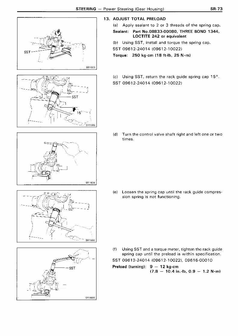
13. ADJUST TOTAL PRELOAD
I I (a) Apply sealant to 2 or 3 threads of the spring cap.
SST
. SST
Sealant: Part No.08833-00080, THREE BOND 1344, LOCTITE 2 4 2 or equivalent
(b) Using SST, install and torque the spring cap.
SST 0961 2-2401 4 (0961 2-1 0022)
Torque: 250 kg-cm (18 ft-lb, 25 N.m)
(c) Using SST, return the rack guide spring cap 15O.
SST 0961 2-2401 4 (0961 2-1 0022)
(d) Turn the control valve shaft right and left one or two times.
(e) Loosen the spring cap until the rack guide compres- sion spring is not functioning.
( f ) Using SST and a torque meter, tighten the rack guide spring cap until the preload is within specification.
SST 0961 2-2401 4 (0961 2-1 00221, 0961 6-0001 0
Preload (turning): 9 - 1 2 kg-cm (7.8 - 10.4 in.-lb, 0 . 9 - 1 .2 Nmm)

SR-74 STEERING - Power Steerina (Gear Housina)
14. INSTALL RACK GUIDE SPRING CAP LOCK NUT
(a) Apply sealant to 2 or 3 threads of the lock nut.
Sealant: Part No.08833-00080, THREE BOND 1344, LOCTITE 242 or equivalent
(b) Using SST, install and torque the lock nut.
SST 0961 2-2401 4 (0961 2-1 0022, 0961 7-24020)
Torque: 570 kg-cm (41 ft-lb, 56 N-m)
HINT: Use a torque wrench with a fulcrum length of 340 mm (13.39 in.).
(c) Recheck the total preload.
15. INSTALL DUST COVER
16. INSTALL CLAW WASHERS AND RACK ENDS
(a) Install new claw washers.
(b) Using SST, install and torque the rack ends.
SST 0961 2-2401 4 (0961 7-2401 1 ) 0961 7-1 401 0
Torque: 940 kg-cm (68 ft-lb, 9 2 Nmm)
HINT: Use a torque wrench with a fulcrum length of 425 mm (16.73 in.).
17. STAKE CLAW WASHERS
Using a brass bar and hammer, stake the two claw washers.
18. INSTALL RACK BOOTS, CLAMPS AND CLIPS
(a) Insure that the tube hole is not clogged with grease.
HINT: If the tube hole is clogged, the pressure inside the boot will change after it is assembled and the steering wheel turned.

STEERING - Power Steering (Gear Housing) SR-75
Matchmarks I
(b) Install the boots.
HINT: Be careful not to damage or twist the boots.
(c) Install the clamps with the ends facing downward.
(dl Install the clips with the ends facing outward.
19. INSTALL TIE ROD ENDS
ia) Screw the tie rod ends onto the rack ends until the matchmarks are aligned.
(b) After adjusting toe-in, torque the clamp nuts.
20. INSTALL RIGHT AND LEFT TURN PRESSURE TUBES
(a) Install new four union seats.
(b) Using SST, install and torque the tubes.
SST 09633-00020
Torque: Valve housing side 2 0 0 kg-cm ( 1 4 ft-lb, 2 0 N.m) Rack housing side 240 kg-cm (17 ft-lb, 2 4 N.m)
HINT: Use a torque wrench with a fulcrum length of 300 mm (1 1.81 in.).

SR-76 STEERING - Power Steering (Gear Housing)
COMPONENTS (wl PPS)
Clip
I
Pressure Control Valve
Control Valve Housing
1 300 (22, 29) 1 -1 Dust Cover
urn' Pressure Tube wm R
6@
+Oi l Seal
Rack Boot
Snap
Cylinder End Stopper
Rack Guide
* Rack Guide Spring Cap
Rack End
Tie
Spring
* Lock Nut
Control Valve
Upper Bearing
Oil Seal
Spacer
Lower Bearing
Self-Locking Nut
I Washer *Rack tibusing Cap
Teflon ~ i n g - - 4
+ 0-Ring @
Rack
/ kg-cm (ft- lb, ~ . m ) ] : Specified torque
+ Non-reusable part * Precoated part * For use wi th SST

STEERING - Power Steering (Gear Housing) SR-77
SST I
Matchmarks
DISASSEMBLY OF STEERING GEAR HOUSING
CLAMP GEAR HOUSING IN VISE
Using SST, secure the steering gear in a vise.
SST 096 1 2-0001 2
REMOVE RIGHT AND LEFT TURN PRESSURE TUBES
(a) Remove the t w o union bolts and four gaskets.
(b) Using SST, remove the pressure tubes.
SST 09633-00020
REMOVE TIE ROD ENDS
(a) Loosen the clamp lock nut and place matchmarks on the tie rod tube and rack end.
(b) Remove tie rod ends.
REMOVE RACK BOOTS, CLAMPS AND CLIPS
REMOVE RACK ENDS AND CLAW WASHERS
(a) Unstake the claw washers.
NOTICE: Avoid any impact to the rack.
(b) Using SST, remove the rack ends.
SST 0961 2-2401 4 (0961 7-2401 1) 0961 7-14010
(c) Remove the claw washers.

SR-78 STEERING - Power Steering (Gear Housing)
I SST I
6. REMOVE RACK GUIDE SPRING CAP LOCK NUT
Using SST, remove the rack guide spring cap lock nut.
SST 096 1 2-2401 4 (096 1 7-24020)
7. REMOVE RACK GUIDE SPRING CAP
Using SST, remove the rack guide spring cap.
SST 0961 2-2401 4 (0961 2-1 0022)
8 . REMOVE RACK GUIDE SPRING, RACK GUIDE AND SEAT
9. REMOVE RACK HOUSING CAP
10. REMOVE SELF-LOCKING NUT
Using SST, remove the self-locking nut.
SST 096 1 6-0001 0
11. REMOVE DUST COVER

STEERING - Power Steering (Gear Housing) SR-79
12. REMOVE CONTROL VALVE HOUSING
(a) Place matchmarks on the valve housing and rack housing.
(b) Using a hexagon wrench, remove the t w o bolts.
(c) Pull out the valve wi th the valve housing.
(d) Remove the O-ring from the rack housing.
13. REMOVE CONTROL VALVE
Using a plastic hammer, tap out the control valve.
14. REMOVE LOWER BEARING AND SPACER
15. REMOVE CYLINDER END STOPPER, SPACERS, OIL SEAL AND RACK
(a) Using snap ring pliers, remove the snap ring.
(b) Using SST, press the rack until the end stopper slightly touches the press block.
SST 0961 2-2401 4 (0961 2-1 0061 )
(c) Pull out the rack with the cylinder end stopper, t w o spacers and oil seal.
HINT: If necessary, slightly tap the rack end with a brass bar and hammer.
SR-80 STEERING - Power Steering (Gear Housing)
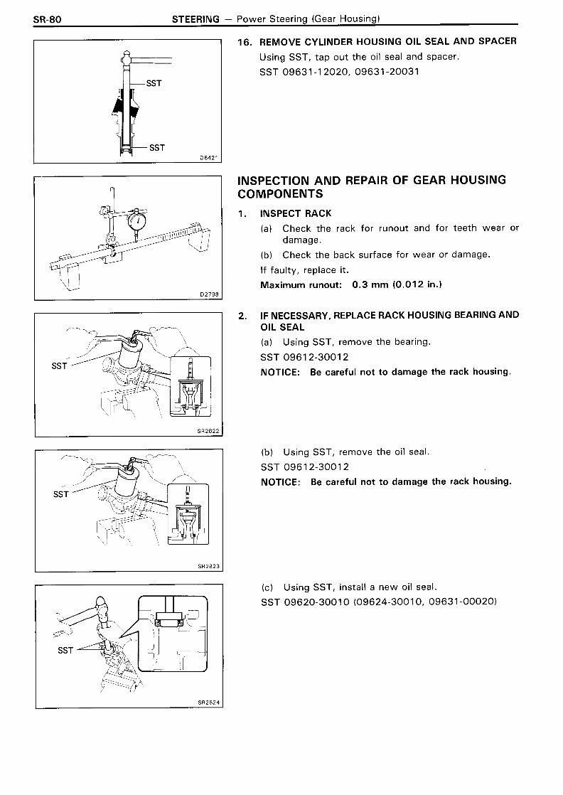
16. REMOVE CYLINDER HOUSING OIL SEAL AND SPACER
Using SST, tap out the oil seal and spacer.
SST 0963 1-1 2020, 09631 -20031
INSPECTION AND REPAIR OF GEAR HOUSING COMPONENTS
1. INSPECT RACK
(a) Check the rack for runout and for teeth wear or damage.
(b) Check the back surface for wear or damage.
If faulty, replace it.
Maximum runout: 0 . 3 mm (0 .012 in.)
2. IF NECESSARY, REPLACE RACK HOUSING BEARING AND OIL SEAL
(a) Using SST, remove the bearing.
SST 0961 2-3001 2
NOTICE: Be careful not to damage the rack housing.
(b) Using SST, remove the oil seal.
SST 096 1 2-300 1 2
NOTICE: Be careful not to damage the rack housing.
(c) Using SST, install a new oil seal.
SST 09620-3001 0 (09624-3001 0, 09631 -00020)

STEERING - Power Steering (Gear Housing) SR-81
SST
b SST
(d) Using SST, press in a new bearing.
SST 09620-3001 0 (09626-3001 0, 09631 -00020)
IF NECESSARY, REPLACE CONTROL VALVE HOUSING OIL SEAL AND BEARING
(a) Using SST, press out the oil seal with the bearing.
SST 09630-2401 3 (09620-2401 01, 09631 -1 2020
(b) Using SST, press in a new oil seal.
SST 09630-2401 3 (09620-24020),09631-12020
(c) Using SST, press in a new bearing.
SST 09630-24Ol3 (09620-24030), 09631 - 1 2020
IF NECESSARY, REPLACE TEFLON RING AND O-RING
(a) Remove the teflon ring and O-ring.
NOTICE: Be careful not to damage the steering rack.
(b) Install a new O-ring.
(c) Expand a new teflon ring with your fingers.
NOTICE: Be careful not to over-expand the teflon ring.

SR-82 STEERING - Power Steering (Gear Housing)
Ring
SST
SST
(dl Install the teflon ring to the steering rack.
(e) Coat the teflon ring with power steering fluid and snug it down with your fingers.
5. IF NECESSARY, REPLACE CONTROL VALVE TEFLON RINGS
(a) Using a screwdriver, remove the teflon rings.
NOTICE: Be careful not to damage the control valve.
(b) Install new teflon rings to SST and expand them.
SST 09631 -20070
(c) Install the expanded teflon rings to the control valve.
(d) Coat the teflon rings wi th power steering fluid, and snug them down with your fingers.
NOTICE: Be careful not to damage the teflon rings.
(el Carefully slide the tapered end of the SST over the teflon rings to seat the rings.
SST 0963 1-20081
6. IF NECESSARY, REPLACE HYDRAULIC REACTION CHAMBER TEFLON RINGS AND O-RINGS
(a) Remove the teflon rings and O-rings.
NOTICE: Be careful not to damage the control valve.
(b) Install t w o new O-rings.
(c) Expand new teflon rings wi th your fingers.
NOTICE: Be careful not t o over-expand the teflon rings.
STEERING - Power Steering (Gear Housing) SR-83
SST I
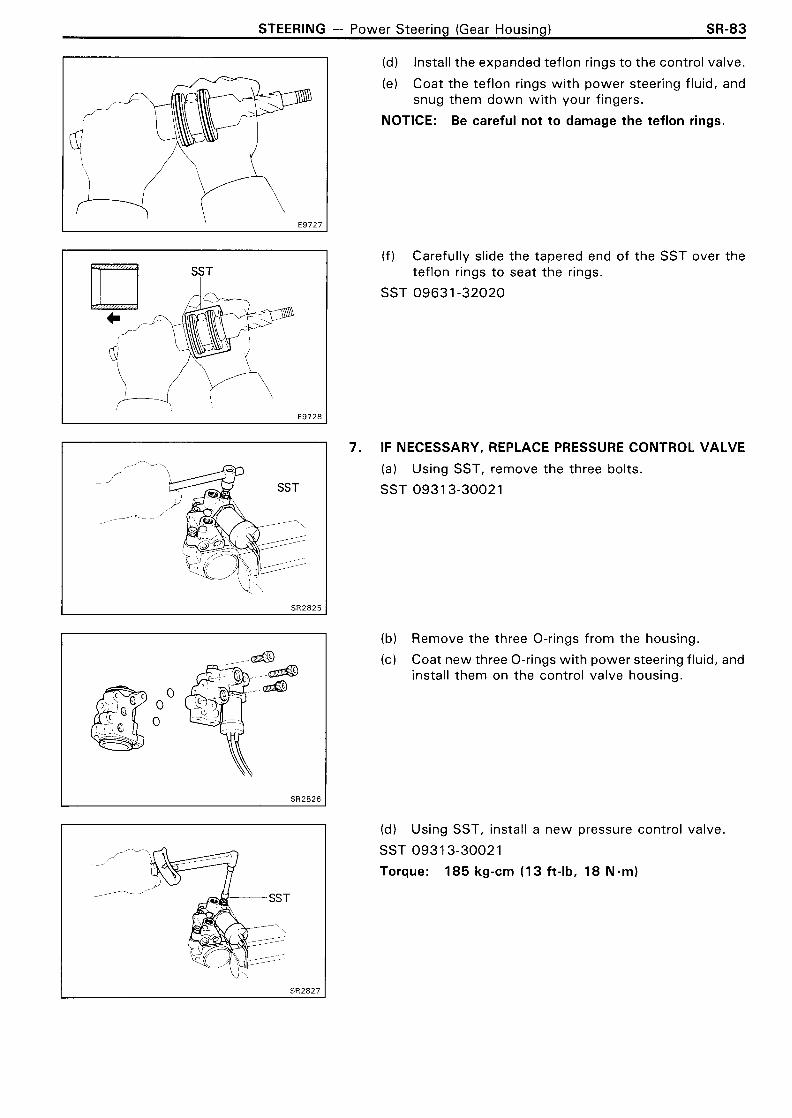
(d l Install the expanded teflon rings to the control valve.
(el Coat the teflon rings wi th power steering fluid, and snug them down with your fingers.
NOTICE: Be careful not to damage the teflon rings.
( f ) Carefully slide the tapered end of the SST over the teflon rings to seat the rings.
SST 09631 -32020
IF NECESSARY, REPLACE PRESSURE CONTROL VALVE
(a) Using SST, remove the three bolts.
SST 0931 3-30021
(b) Remove the three O-rings from the housing.
(c) Coat new three O-rings with power steering fluid, and install them on the control valve housing.
(dl Using SST, install a new pressure control valve.
SST 093 1 3-30021
Torque: 185 kg-cm (1 3 ft-lb, 18 Nmm)

SR-84 STEERING - Power Steering (Gear Housing)
ASSEMBLY OF STEERING GEAR HOUSING (See page SR-76)
1. COAT POWER STEERING FLUID OR GREASE ON FOLLOW- ING PARTS:
C : Molybdenum disulphide lithium base grease
@ : Power steering fluid sf32944
2. INSTALL CYLINDER HOUSING OIL SEAL AND SPACER
(a) Coat a new oil seal lip wi th power steering fluid.
(b) Insert SST into the oil seal and spacer.
SST 09631 -1 2020, 09631 -3201 0
(c) Tap in the spacer and oil seal softly.
INSTALL RACK
(a) Install SST to the rack.
HINT: If necessary, scrape the burrs off the rack teeth end and burnish.
SST 09631 -201 02

STEERING - Power Steering (Gear Housing) SR-85
SST
(b) Coat SST with power steering fluid.
(c) Insert the rack into the cylinder.
(d) Remove SST.
4. INSTALL CYLINDER END STOPPER, OIL SEAL AND SPACERS
(a) To prevent oil seal lip damage, wind vinyl tape on the steering rack end, and apply power steering fluid.
(b) Install the oil seal by pushing it into the cylinder in the direction shown in drawing, without tilting.
(c) Install the two spacers.
(d) Using SST, drive in the cylinder end stopper.
SST 09620-3001 0 (09627-3001 0, 09631 -00020)
(el Using snap ring pliers, install the snap ring.

SR-86 STEERING - Power Steering (Gear Housing)
AIR TIGHTNESS TEST [TEST 11
(a) Install SST to the unions of the cylinder housing.
SST 09631 -1 2070
(b) Apply 400 mmHg (1 5.75 in.Hg, 53.3 kPa) of vacu- um for about 30 seconds.
(c) Check that there is no change in the vacuum.
If there is change in the vacuum, check the oil seals instal- lation.
[TEST 21
(a) Remove the L joint from SST.
SST 0963 1-1 2070
(b) Install L joint to the union of the cylinder end side.
(c) Apply 400 mmHg (1 5.75 in.Hg, 53.3 kPa) of vacu- um for about 30 seconds.
(dl Check that there is no change in the vacuum.
If there is change in the vacuum, check the teflon ring and O-ring of the rack.
INSTALL CONTROL VALVE
(a) Coat the teflon rings with power steering fluid.
(b) Push the control valve into the housing.
INSTALL CONTROL VALVE HOUSING
(a) Coat a new O-ring with power steering fluid, and in- stall i t to the housing.
(b) Align the matchmarks on the valve housing and rack housing.
(c) Using a hexagon wrench, temporarily tighten the two bolts.
(dl Using SST, tighten the two bolts.
SST 093 1 3-30021
Torque: 185 kg-cm (13 ft-lb, 18 Nmm)
INSTALL LOWER BEARING AND SPACER

STEERING - Power Steering (Gear Housing) SR-87
SST
9. INSTALL SELF-LOCKING NUT
Using SST, install a new self-locking nut.
SST 096 1 6-000 1 0
Torque: 600 kg-cm (43 ft-lb, 59 N-m)
10. INSTALL RACK HOUSING CAP
(a) Apply sealant to 2 or 3 threads of the cap.
Sealant: Part No. 08833-00080, THREE BOND 1344, LOCTITE 242 or equivalent
(b) Install the cap.
Torque: 700 kg-cm (51 ft-lb, 69 N.m)
(c) Using a pin punch and hammer, stake the cap.
11. INSTALL RACK GUIDE SEAT, RACK GUIDE AND RACK GUIDE SPRING
12. ADJUST TOTAL PRELOAD
(a) Apply sealant to 2 or 3 threads of the spring cap.
Sealant: Part No. 08833-00080, THREE BOND 1344, LOCTITE 242 or equivalent
(b ) Using SST, install and torque the spring cap.
SST 0961 2-2401 4 (0961 2-1 0022)
Torque: 250 kg-cm (18 ft-lb, 25 Nmm)

SR-88 STEERING - Power Steering (Gear Housing)
Fulcrum Length,
(c) Using SST, return the rack guide spring cap 15O.
SST 096 1 2-240 1 4 (096 1 2- 10022)
(d) Turn the control valve shaft right and left one or two times.
(el Loosen the spring cap until the rack guide compres- sion spring is not functioning.
( f) Using SST and a torque meter, tighten the rack guide spring cap until the preload is within specification.
SST 0961 2-2401 4 (0961 2-1 0022), 0961 6-0001 0
Preload (turning): 9 - 12 kg-cm (7.8 - 10.4 in.-lb, 0 .9 - 1.2 N.m)
13. INSTALL RACK GUIDE SPRING CAP LOCK NUT
(a) Apply sealant to 2 or 3 threads of the lock nut.
Sealant: Part No.08833-00080, THREE BOND 1344, LOCTITE 242 or equivalent
(b) Using SST, install and torque the lock nut.
SST 0961 2-2401 4 (0961 2-1 0022, 0961 7-24020)
Torque: 570 kg-cm (41 ft-lb, 56 N-m)
HINT: Use a torque wrench with a fulcrum length of 340 mm (1 3.39 in.).
(c) Recheck the total preload.
14. INSTALL DUST COVER
15. INSTALL CLAW WASHERS AND RACK ENDS
(a) Install new claw washers.
(b) Using SST, install and torque the rack ends.
SST 09612-24014 (09617-2401 I), 09617-14010
Torque: 940 kg-cm (68 ft-lb, 9 2 N.m)
HINT: Use a torque wrench with a fulcrum length of 340 mm (13.39 in.).
(c) Using a brass bar and hammer, stake the claw washers.

STEERING - Power Steering (Gear Housing) SR-89
Matchmarks
16. INSTALL RACK BOOTS, CLAMPS AND CLIPS
(a) Insure that the tube hole is not clogged with grease.
HINT: If the tube hole is clogged, the pressure inside the boot will change after it is assembled and the steering wheel turned.
(b) lnstall the boots.
HINT: Be careful not to damage or twist the boots.
(c) lnstall the clamps.
(dl lnstall the clips wi th the ends facing outward.
17. INSTALL TIE ROD ENDS
Screw the tie rod ends onto the rack ends until the match- marks are aligned.
18. INSTALL RIGHT AND LEFT TURN PRESSURE TUBES
(a) lnstall t w o new union seats.
(b) Using SST, tighten the nuts.
SST 09633-00020
Torque: 240 kg-cm (1 7 ft-lb, 2 4 N.m)
HINT: Use a torque wrench with a fulcrum length of 3 0 0 mm (1 1.81 in.).
(c) lnstall the union bolts over the new gaskets and tor- que them.
Torque: 350 kg-cm (25 ft-lb, 34 N-m)

SR-90 STEERING - Power Steering (Progressive Power Steering)
Progressive Power Steering (PPS) ELECTRONIC CIRCUIT
Do not open the cover or the case of the ECU and various computer unless absolutely necessary. (If the IC termin.als are touched, the IC may be destroyed by static electricity.)
Power
J-
Gear Housing
Flow Dividing Valve
Solenoid Valve
Ignition Fuse (ECU-IG) , ECU
Switch
Fusible Link
Battery
4 Valve
Speed Sensor
SOL @
SOL 0

STEERING - Power Steering (Progressive Power Steering) SR-9 1
TROUBLESHOOTING
Trouble
Hard steering at idle or low-speed driving.
Steering too sensitive during high-speed driving.
Preliminary Check
Check tire pressure.
Check lubrication of suspension and steering linkage.
Check front wheel alignment.
Check steering system joint and suspension arm ball joint.
Check for bent steering column.
Check that all connectors are secure.
Check PS pump fluid pressure. (See page SR-43)
I Turn ignition switch on. I
I
1 Fuse faulty.
No
--
r k c o n n e c t the ECU connector. I
Check 1. Check that there is the battery voltage between the ECU terminal +B and body ground.
Short circuit in wire harness between fuse and ECU terminal +B.
Is ECU-IG fuse normal? Replace fuse. I s operation normal?
1 Yes
I
-
t Open circuit in wire harness between the fuse and ECU terminal +B.
Yes Yes
CONTINUED ON NEXT PAGE

SR-92 STEERING - Power Steering (Progressive Power Steering)
Yes CONTINUED FROM PREVIOUS PAGE
SPD
Open circuit in wire harness between the ECU terminal I GND and body ground. Body ground faulty.
Yes
Check 2. Check that there is continuity between the ECU terminal GND and body ground.
Check 3. (a) Jack up the rear wheel on one side. (b) Connect an ohmmeter between the ECU connector
terminals SPD and GND. (c) Spin the rear wheel and check'that the meter needle
deflects from 0 R to m R.
Open or short circuit in wire harness between the ECU terminal SPD and speed sensor. Speed sensor faulty (See page BE-84). I
Check 4. Check that there is no continuity between terminals SOL @ or SOL a and GND.
Yes No
7 Short circuit in wire harness between the terminals SOL @ andSOL @ . Solenoid valve faulty.
CONTINUED ON NEXT PAGE

STEERING - Power Steering (Progressive Power Steering) SR-93
I Yes
CONTINUED FROM PREVIOUS PAGE
Check 5. Measure the resistance between terminals SOL @ and SOL 0. Standard resistance: 6.0 - I I .O Cl
t Open circuit in wire harness between the terminals SOL @ andSOL @ . Solenoid valve faulty.
Check 6. Bad
l nspect ECU. Replace ECU.

SR-94 STEERING - Power Steerina (Proaressive Power Steerina)
ELECTRONIC CONTROL SYSTEM
Solenoid Valve
Coil
Spring
Valve
ON-VEHICLE INSPECTION
1. DISCONNECT WIRING CONNECTOR
2. MEASURE RESISTANCE
Measure the resistance between SOL @ and SOL 8. Resistance: 6.0 - 11 .O !J
3. CHECK SOLENOID OPERATION
(a) Connect the battery positive terminal t o the solenoid terminal SOL a.
(b) Connect the battery negative terminal t o the solenoid terminal SOL a.
(c) Check that the solenoid is clicked.
If faulty, replace the pressure control valve w i th the sole- noid valve.
NOTICE: Do not apply voltage for more than 30 seconds to avoid burning out the solenoid. If repeating this step, wait until the solenoid cools down enough that it can be touched by hand.
4. CONNECT WIRING CONNECTOR

STEERING - Power Steering (Progressive Power Steering) SR-95
Power Steering ECU
INSPECTION OF ECU
1. JACK UP VEHICLE AND SUPPORT IT ON STANDS
2. REMOVE GLOVE BOX
HINT: Do not disconnect the ECU connector.
3. START ENGINE
4. MEASURE VOLTAGE OF ECU
(a) Using a voltmeter, measure the voltage between ECU terminals SOL a a n d GND while the engine is idling.
Standard voltage: 0 . 3 2 - 0 . 4 4 V
(b) Place the transmission in gear and while running at about 50 kmlh (31 mph), measure the voltage be- tween ECU terminals SOL @ and GND.
Standard voltage: Voltage measured in (a) above, minus 0 . 0 9 - 0 . 2 3 V
If no voltage, try another ECU.
5. INSTALL GLOVE BOX
6. LOWER VEHICLE

- MEMO -