Embed Size (px)
Citation preview

1987 URSI RADIO SCIENCE MEETING INTERNATIONAL. UNION OF RADIO SCIENCE
Program and Abstracts
I
1
June 15th-19th 1987
I· _,
Virginia Polytechnic Institute & State University Blacksburg, Virginia 24061
I I
,._.··-----------------'' :

----------·---------·---------- ------ -------------
TECHNICAL PROGRAM SUMMARY
TIME ROOM MONDAY, JUNE 15 TUESDAY, JUNE 16 WEDNESDAY, JUNE 17 THURSDAY, JUNE 18 FRIDAY, JUNE 19
B JB01 GUIDED WAVES I UB07 GUIDING STRUC JB12 TRANSIENTS
C AP01 PROP MODEL AP 10 GAUSS I AN BEAMS JB13 REMOTE SENSING
D/E AP02 ADAPTIVE ANT AP11 OPTICS IN ANT ARRAY DESIGN SHORT COURSE
8:30 AM· F UBD 1 RANDOM MED I A I JB06 PROP MEAS 12:00 NOON G UB02 EM THEORY I AP12 RE FLEC ANT I UB15 RANDOM MEDIA I I
AUD AP03 NUM METH I JB07 COMP & SUPERCOMP PLENARY SESSION UB16 SCAT & DI FF VI GTD SHORT COURSE
OD UB03 SCAT & DI F I AP13 SCAT & DIF Ill UB17 NUM METH IV AMTA ANECHOIC CHAMBER WORKSHOP
EC AP04 PH ARRAY SYN AP14 MULTIPLE BEAM SYS
IIC JA01 NEAR FIELD AP15 COMP BASED INS·!!
REH AP05 S/C ANT I UB08 ANTENNAS 11 AP24 S/C ANT l l l APS MMIC IIORKSHOP
T JB02 ANTENNAS I JB08 MICRO & PRINTED AP25 MICRO ELEMNT
AP·S ANT STAND COMM· AP·S MEAS COMM· AP·S REVIEIIERS LUNCH· LUNCHEON FOR S. C. NOON CEC ALUMNI LNG CEC DIN RM CEC DIN RM AND IIORKSHOPS ·
AP· S IIAVE PROP STAND CEC DIN RM COMM·CEC DIN RM
MEETING ROOM DESIGNATIONS
CEC ROOMS: B, C, D/E, F, G, Auditoriun (AUD) SQUIRES ,ROOMS: Old Dominion (OD), East Conrnonwealth (EC), llest Conrnonwealth (IIC), Rehearsal Room (REH), Theatre (T)

NATIONAL ACADEMIES OF SCIENCE AND ENGINEERING NATIONAL RESEARCH COUNCI~
OF THE UNITED STATES
1987 RADIO SCIENCE MEETING
PROGRAM AND ABSTRACTS
SPONSORED BY
THE UNITED STATES NATIONAL COMMITTEE FOR URS!
VIRGINIA POLYTECHNIC INSTITUTE
AND STATE UNIVERSITY
BLACKSBURG, VA
JUNE 15-19, 1987
1987 IEEE ANTENNAS AND PROPAGATION SOCIETY
INTERNATIONAL SYMPOSIUM AND
URS! RADIO SCIENCE MEETING JUNE 15-19
WELCOME TO VIRGINIA TECH
On behalf of the 1987 IEEE Antennas and Propagation Society International Symposium and URSI Radio Science Meeting Steer.ing Committee I extend a warm welcome. The meetings will be held on the campus of Virginia Polytechnic Institute and State University (Virginia Tech) in Blacksburg, Virginia. Viginia Tech is a land grant university with strong programs in engineering and agriculture. Blacksburg is in the high valley between the Allegheny and Blue Ridge Mountains near Roanoke, Virginia. The rural location of the campus provides a setting conducive to technical and social interactions.
The technical program includes several special sessions on current topics and an outstanding Plenary Session to be held on June 17. This collection of URS! abstracts serves as the official guide to the URS! Radio Science Meeting.
For the second year we will hove exhibits by antenna and microwave companies that provide products and services of interest to our attendees. Plan to stop by the exhibition booths located on the first floor of Squires Student Center; they will be open Monday through Thursday. Immediately following the conference on Friday, June 19, there will be three short courses and two workshops. For a nominal cost conference attendees may extend their stay and pick up state-of-the-art information. The AP-S short courses are Microwave Array Design, Adaptive Processing Antenna Systems, and Geometrical Theory of Diffraction. The AP-S workshop is a continuation of last year's symposium workshop on MMIC in arrays. The AMTA workshop is on anechoic chambers.
This year's social program is packed with both daytime and evening events you will want to participate in. The kickoff event is An Olde Virginia Welcome on Sunday evening. Monday night is the Virginia Hors d'Oeuvres Dinner. Tuesday evening the Appalachian Barbecue includes an outdoor barbecue followed by a special program of Appalachian music by John Mccutcheon. The Awards Banquet will be Wednesday night. Daytime social events include a tour of historic Lexington.
Viginia is rich in Colonial, Revolutionary War, and Civil War history as well as natural beauty. Be sure to experience some of Virginia during.your stay.
Warren L. Stutzman General Chairman, Steering Committee
ii

THE STEERING COMMITTEE
GENERAL CHAIRMAN Warren L. Stutzman
VICE CHAIRMAN AND FINANCE Daniel B. Hodge
TECHNICAL PROGRAM Charles W. Bostian
PUBLICATIONS PUBLICITY David A. deWolf Gary S. Brown
URS! LIAISON Ioannis M. Besieris
REGISTRATION William A. Davis
LOCAL ARRANGEMENTS SOCIAL ACTIVITIES Claudia J. Stutzman Richard 0. Claus
SYMPOSIUM SECRETARY Wendy L. Maroney
TECHNICAL PROGRAM COMMITTEE
AP-S REPRESENTATIVES
Charles W. Bostian Chalmers M. Butler Robert E. Collin R. T. Compton William English Edmund S. Gillespie Robert W. Grunner Hussain Haddad
Louis J. Ippolito Roger H. Lang Robert J. Mailloux Edmund J. Miller James W. Mink Y. Rahmat-Sami i Charles A. Raquet David V. Rogers
URS! REPRESENTATIVES
Ioannis M. Besieris Akira Ishimaru
Tapan K. Sarkar John Schindler Helmut E. Schrank Roland Schwerdtfeger Felix Schwering W. Ross Stone Warren L. Stutzman Richard Ziolkowski
Sedki M. Riad
Session
JB01 UB01 UB02 UB03 JAOl JB02 JB03 JB04 UB04 UB05 UAOl JA02 JB05 UB06 JA03 UB07 JB06 JB07
UB08 JB08 JB09 UB09 UB10 UB11 JB10 UB12 UB13 UB14 JB11
JB12 JB13 UB15 UB16 UB17 UB18 UB19
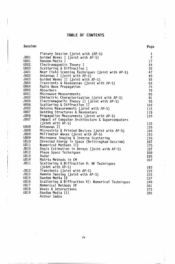
TABLE OF CONTENTS
Plenary Session (joint with (AP-S) Guided Waves I (joint with AP-S) Random Media I Electromagnetic Theory I Scattering & Diffraction I Near Field Scanning Techniques (joint with AP-S) Antennas I (joint with AP-S) Guided Waves II (joint with AP-S) Transients & Resonances (joint with AP-S) Radio Wave Propagation Absorbers Microwave Measurements Dielectric Characterization (joint with AP-S) Electromagneitc Theory II (joint with AP-S) Scattering & Diffraction II Antenna Measurements (joint with AP-S) Guiding Structures & Resonators Propagation Measurments (joint with AP-S) Impact of Computer Architecture & Supercomputers (joint with AP-S) Antennas II Microstrip & Printed Devices (joint with AP-S) Millimeter Waves (joint with AP-S) Microwave Imaging & Inverse Scattering Directed Energy in Space (Brittingham Session) Numerical Methods III Angle Estimation in Arrays (joint with AP-S) Phase Space Techniques Radar Matrix Methods in EM Scattering & Diffraction V: HF Techniques (joint with AP-S) Transients (joint with AP-S) Remote Sensing (joint with AP-S) Random Media II Scattering & Diffraction VI: Numerical Techniques Numerical Methods IV Waves & Interactions Random Media III Author Index
iv
Page
1 7
17 23 35 47 49 55 63 73 79 85 91 95
103 115 119 129
133 135 145 153 155 167 175 187 189 195 207
215 225 233 237 249 261 273 285

WEDNESDAY AM - PLENARY SESSION
PLENARY SESSION Chairman: C. W. Bostian, Virginia Tech
Organizer: Prof. C. W. Bostian Room: CEC, Auditorium Time: 8:30-11:50
8:40 TRENDS IN THE DEVELOPMENT OF ARRAYS Allan C. Schell, Rome Air Development Center
9: 20 SOME NEW TOPICS IN WAVE PROPAGATION Walter A. Flood Jr, US Army Research Office
10:00 COFFEE BREAK
2
4
10:30 COMPACT RANGES - PAST, PRESENT, AND FUTURE 5 W. Dennis Burnside, The Ohio State University
11:10 INVERSE SCATTERING: THEORY AND APPLICATIONS 6 Anthony J. Devaney, Schlumberger-Doll Research Center
1

TRENDS IN THE DEVELOPMENT OF ARRAYS
Allan C. Schell Electromagnetics Directorate
Rome Air Development Center Bedford, MA 01731
Since the earliest days of electromagnetic applications, arrays have been an important part of antenna technology. Marconi used an array feed for his demonstration of point-to-point VHF communications. The arrays that are under consideration today are the product of several stages of development in response to two persistent trends: the need for better pattern control, and the drive toward higher frequencies.
The first stage of non-inertial beam steering involved the use of electromechanical phase shifters. Several forms of phased arrays were developed from concepts originating in laboratories during World War II. The feed array for the first ballistic missile warning radar reflectors used this form of beam scanning.
The fielding of true phased arrays awaited the development of phase shifters of sufficient efficiency, power handling capability, and reliability to challenge the mechanically rotated antennas of the time. An intermediate development was the frequency scanned antenna, typically employing a serpentine waveguide feed to progressively increase the phase in the vertical plane vs frequency. Large billboard phased arrays were constructed on U.S. naval ships in the late 1950's, and a full phased array employing phase shifters was constructed at this time at Eglin Air Force Base, Florida, for space tracking operations.
A major thrust of phased array development has been the modular approach to design. Several versions of airborne phased arrays using plug-in modules operating in the SHF bands have been built and tested, culminating in the electronically agile radar antenna currently in use. Several designs of ground based antennas have used modules for the elements of array lenses. The "space fed" lens offered an effective radiating structure with some improvement in affordability.
A new stage of phased array development began with the increasing use of stripline for radiating elements and feed circuitry. This tended to promote the development of the array in planes transverse to the array boresight, in contrast to the "in-line" approach of modular arrays. As the quality of stripline circuitry improved, phase shifters were incorporated in the distribution network.
2
The realization of transversely fed phased arrays for the millimeter wave bands has recently focussed on the development of subarrays on a chip. A typical architecture locates four or more radiators with the attendant phase control and amplifiers on a gallium arsenide substrate. Advances in microwave monolithic integrated circuit technology show promise of raising the yield of these complex circuits to levels adequate for arrays of moderate size.
The next generation of phased arrays is finding its development strongly impacted by advances in signal processing. Digital beamforming is coming into use as the result of greatly expanded speeds of analog-to-digital converters and processors. Using very large scale integration, miniature processors for beam control, adaptivity, testing, and repair can be located at or near the array face. The subarray can begin to take on elements of local control, adjusting its power and wavefront to meet the needs of interference, device failure, or alternative modes of .operation. Functions of a higher order are relegated to deeper layers of the array, where system commands are translated and distributed, and assessments of overall array capability can be conducted. As the technology of microwave monolithic integrated circuitry continues to progress, non-reciprocal components such as isolators and circulators will be incorporated lithographically in chip circuitry. These extensions of integrated circuits are leading to the goal of a fully "printed" phased array.
3
Some New l~i cs in ~lave Propagation Walter A. Flood
U.S. Army Research Office
In the last few years, the results of innovative experiments on scattering by particles and scattering from rough surfaces have challenged our ability to "explain" and predict the outcome of certain experiments in this area. I propose to discuss a few of these experiments and indicate where we stand in terms of physical theories to explain them. The experiments are described in the references listed below.
The first two experiments involve multiple scattering by particles and the need to account for the position correlation between pairs of particles. These experiments, performed at optical wavelengths and reported in optical journals, are relevant to remote sensing and radar clutter problems.
The third set of experiments is relatively new and was first published in January 1987 (again in an optical journal). These results formed the basis for a Special Session at the January 1987 Radio Science meeting in Roulder, Colorado. The data show that when a sufficiently rough surface (large rms slope and rms height fluctuation) is illuminated by a coherent field, the largest return is in the anti-specular or backscatter direction. This result appears to hold for almost all angles of incidence. There is no surface scattering theory available today which can explain the data although one theory has some promise. These last experiments have challenged theoreticians and provide a set of well-characterized surfaces against which to compare theories and models currently used in remote sensing, propagation, and clutter analysis.
The final set of experiments were necessarily performed at optical wavelengths and reported in the optical 1 iterature. They show a very spectacular set of observations which, when carefully interpreted, admit of more or less classical electromagnetic explanations. These results are germane to the limitation on the propagation of high intensity laser beams in the atmosphere.
The ability of current theories to explain these observations will be discussed and new experiments to guide theoretical developments will be indicated.
REFERENCES
1) A. Ishimaru and Y. Kuga "Attenuation Constant of a Coherent Field in a Dense Distribution of Particles", JOSA J.J., 1317-1320, (1982).
2) Y. Kuga and A. Ishimaru, "Retroreflectance 'from a dense distribution of spherical particles", JOSA A,_!_, 831-235, (1984).
3) E. R. Mendez and K. A. O'Donnell, "Observations of Depolarization and Backscattering Enhancement in Light Scattering from Gaussian Random Surf aces", Optics Communications,~. 91-%, (1987).
4) R. K. Chang et al , "Stimulated Raman Scattering, Phase Modulation and Coherent Anti-Stokes Raman Scattering from Single Micrometer Size, Liquid Droplets", Methods of Laser Spectroscopy by Y. Prior, A. Ben-Rueven, and M. Rosenbluh, Eds. [Plenum Press, N.Y., 1986 p. 249]
4

"COMPACT RANGES - PAST, PRESENT, AND FUTURE"
by
Walter Burnside Professor Department of Electrical Engineering Ohio State University
ABSTRACT
The compact range has been used for electromagnetic measurements since the early 1950's. Although the early attempts with sue~ systems had some successes, they were not generally used until the middle of the 1970's. This recent interest was sparked by a commercially available system developed by Scientific-Atlanta. This system was specifically designed .and tested for antenna applications, even though the earlier tests were made in terms of
scattering measurements. Based on the recent interest in radar cross-section, the compact range has been re-examined in terms of its capabilities for measuring the scattering properties of large structures. The Ohio State
University has been one of the pioneers in developing the proper use, capabilities, and modifications necessary to make the compact range one of the most accurate electromagnetic pattern measurement systems available. As a result, new systems have been designed using various electromagnetic
analyses to guide this research effort. These changes include the reflector, feeds, target mount, instrumentation, absorber, target handling techniques, data processing, calibration methods, calibration targets, etc. In most
cases, the theoretical solutions have been verified by experimental results, and in some cases, the new designs have been incorporated in commericial
products. The presentation wi 11 attempt to cover the 1 a test and more interesting
aspects of this challenging new area.
5
INVERSE SCATTERING
THEORY AND APPLICATIONS
Anthony J. Devaney
Schlumberger-Doll Research, Ridgefield, CT 06877
The direct or forward scattering problem consists of computing the scattered wavefield generated from the interaction of a known (prescribed) incident wave with an obstacle of known properties, e.g., scattering potential. This problem can be cast in the form of a Fredholm integral equation of the second kind (Lippmann Schwinger equation) relating the unknown scattered wave to the known incident wave and obstacle scattering potential. The inverse scattering problem consists of deducing something about the obstacle from measurements of the scattered field generated in one or more scattering experiments using known (prescribed) incident waves. The inverse problem is, in general, much more difficult than the direct problem since the mapping from the scattered wavefield to the object properties is both non-linear and non-local.
While much is known about the class of direct scattering problems, the systematic investigation of inverse scattering problems is still in its infancy and, with the exception of one-dimensional objects, most of the work to-date has employed linearizing approximations to the mapping from the scattered wavefield to the object properties. This talk will focus on a systematic treatment of the various approaches to inverse scattering theory based on these linearizing approximations and will include a discussion of practical applications of these approaches in electromagnetic inverse scattering.
The linearizing schemes reviewed include the physical optics, Born and Rytov approximations. All three approximations will be shown to lead to the same mathematical structure of the inverse problem which is elegantly expressed in Fourier space as a generalization of the well-known proiection-slice theorem of X-ray tomography .. Applications which admit this structure include diffraction microscopy, inversion from monostatic and bistatic radar measurements, and electromagnetic tomography. Conventional X-ray tomography will be shown to be a limiting case of this general formulation valid when the wavelength of the probing radiation goes to zero.
The generalized projection-slice theorem is shown to lead directly to reconstruction algorithms for the linearized inverse scattering problem for both the multiple view, narrow band case occuring in diffraction microscopy, electromagnetic tomography and certain forms of bistatic radar imaging and the single view, broad band case characteristic of monostatic radar imaging. Both Fourier based and iterative and non-iterative space based reconstruc·tion algorithms will be reviewed. The relationship of the reconstruction algorithms to generalized holographic imaging and the reconstruction algorithms of X-ray tomography will be discussed and a number of computer simulated examples will be presented.
6

MONDAY AM
JOINT SESSION JB01 GUIDED WAVES I
Chairman: S. T. Peng, NY Inst of Tech Room: CEC, Meeting Room B Time: 8:30-12:00
8:40 BOUNDARY ELEMENT METHOD FOR DIELECTRIC WAVEGUIDES 8 AND RESONATORS
D. A. Ksienski, R. E. Collin, Case Western Reserve University
9: 00 0UASI-0PTICS OF THE COUPLING OF GUIDED MODES IN g Two PARALLEL DIELECTRIC WAVEGUIDES S. R. Seshadri, University of Wisconsin
9:20 MODE CONVERSION IN A CYLINDRICAL WAVEGUIDE WITH A 10 PERIODIC STEP CHANGES IN THE RADIUS
R. A. Schill Jr, University of Illinois; S. R. Seshadri, University of Wisconsin
9:40 SCATTERING FROM A THICK DOUBLY-PERIODIC LOSSY 11 SLAB: A MODAL APPROACH
R. E. Jorgenson, R. Mittra, University of Illinois
10:00 A NEW MODAL EXPRESSION OF THE FIELDS ON DIELEC- 12 TRIC WAVEGUIDES OF OPEN TYPE
H. Shigesawa, M. Tsuji, Doshisha University
10:20 COMPLEX MODES IN DIELECTRIC LOADED WAVEGUIDES K. A. Zaki, C. Chen, University of Maryland
10:40 GEGENBAUER POLYNOMIAL BASIS IN GALERKIN'S METHOD: PARALLEL PLATE WAVEGUIDE EXAMPLE
R. W. Scharstien, Clemson Univer'sity
See AP-S Dig.
13
11:00 THEORETICAL ANALYSIS OF SINGLE-MODE CHANNEL 0PTI- 14 CAL WAVEGUIDES MADE BY Two-STEP ION EXCHANGE IN GLASS J. Albert, G. L. Yip, McGill University
11: 20 DESCRIPTION AND APPROXIMATION OF THE CONTINUOUS 15 SPECTRUM FOR DIELECTRIC WAVEGUIDING STRUCTURES
M. S. Viola, D. P. Nyquist, Michigan State University
11:40 SOLUTIONS FOR ELLIPTICAL WAVEGUIDE CONFIGURATIONS See J. C. Wiltse, D. N. Black, Georgia Tech Research Institute AP-S Dig.
7
JBOl-1
BOUNDARY ELEMENT METHOD FOR DIELECTRIC WAVEGUIDES AND RESONATORS
D. A. Ksienski and R. E. Collin Electrical Engineering and Applied Physics Department
Case Western Reserve University Cleveland, Ohio 44106
The electric and magnetic fields in the interior of a dielectric waveguide or resonator can be expressed in terms of the tangential
.-,. .-,. fields Eaxn,
+ + Ha x n on the boundary through an application of
Green's theorem. The formal result is
£ E x ri · VxG dS -jwµ0
£ it x ri · G. ds Js a e Js a e
where G and G are appropriate Green's dyadic functions for the e ID
interior region. Similar equations will express the exterior fields in terms of the boundary values. By enforcing the continuity of the tangential fields across the boundary a pair of dual integral equations for the surface fields are obtained. The formulation is the generalized boundary element or mode matching method and provides a formal way of properly matching interior and exterior modes across an arbitrary surface. The general features of the method will be described with emphasis on the selection of suitable dyadic Green's functions and the numerical solution of the integral equations by the method of moments. Some numerical results will be presented for the rectangular dielectric waveguide and cylindrical resonator. This generalized mode matching method has a number of advantages over commonly used finite element methods.
8

QUASI-OPTICS OF THE COUPLING OF GUIDED MODES IN TWO PARALLEL OIELECTRIC WAVEGUIDES
S. R. Seshadri
JBOI-2
Department of Electrical and Computer Engineering University of Wisconsin-Madison, Madison, Wisconsin 53706
The guided waves supported by two parallel, identical planar dielectric films interact through the evanescent waves in the region between them. The coupled mode equations governing the evanescent wave interaction are deduced by a quasi-optical technique. The attenuation coefficient caused by the losses in the various spatial regions is also determined by the same technique. The coupling constant in the coupled mode equations and the expression for the attenuation coefficient assume simple forms when expressed in terms of the quasi-optical parameters. The details of the transverse electric mode will be presented and the results of the transverse magnetic mode will be summarized. The simplicity of the quasi-optic technique relative to the wave theory is illustrated with a number of examples of parallel waveguides.
9

JBOl-3
MODE CONVERSION IN A CYLINDRICAL WAVEGUIDE WITH A PERIODIC STEP CHANGES IN THE RADIUS
Robert A. Schill, Jr. 1 and S. R. Seshadri 2 lDepartment of Electrical Engineering and Computer Science
University of Illinois at Chicago, Chicago, Illinois 60680 2Department of Electrical and Computer Engineering
University of Wisconsin-Madison, Madison, Wisconsin 53706
For the modes having azimuthal variation in a. cylindrical waveguide having a periodic step changes in the radius, the propagation of modal voltages and currents is investigated for the transverse electric mode. The transfer coefficients are deduced and their values are explicitly determined for small relative changes in the radius. The theory is applied to treat a mode converter in which there is a selective interaction between two forward traveling modes, and the theoretical results are compared with available experimental observations.
10

SCATTERING FROM A TIIlCK. DOUBLY-PERIODIC LOSSY SLAB: A MODAL APPROACH
Roy E. Jorgenson and Raj Mittra Fl«lromagnetic Communicaticn Laboratory
Universil:y of Illinois Urbana, Illinois 61801
JBOl-4
The problem of calculating the electromagnetic scattering characteristics of lossy, doubly-periodic structures has received the attention of several workers in recent years. An example of such a structure is shown in Figure 1. Conventionally, this problem would be analyzed by discretizing the wall volume of the unit cell using the method of moments procedure. If the slab is thick in the z direction, a large number of unknowns may be required to describe the induced current distribution accurately, and its computation may be very time-consuming. An approach to alleviating this problem would be to characterize the fields away from the slab-to-air interface in terms of the modes of the periodic, lossy waveguide structure, with the expectation that only a few of these modes would be required to describe the fields within the structure. Although the modal analysis of PEC waveguides, or of guides with
, lossy walls, is well known, not much has been written in the literature on the topic of characteristic solutions of periodic waveguides with penetrable walls. The periodic, lossy guide modes have a fundamentally different character than their counterparts in conventional waveguides. In this paper we point out these differences and discuss the problem of computing these modes for the waveguide structure shown in Figure 1. Since the walls are lossy, there is no sharp cutoff and the transverse and axial currents become coupled. A sourceless matrix equation is generated via the method of moments and the modes are found numerically by varying the propagation parameter and searching for the minima of the determinant of the impedance matrix.
I\ z
I\ y
Figure 1. Geometry of the lossy periodic slab
11
JBOl-5
A NEW MODAL EXPRESSION OF THE FIELDS ON DIELECTRIC WAVEGUIDES OF OPEN TYPE
Hiroshi Shigesawa and Mikio Tsuji Department of Electronics, Doshisha University
Kamikyo-Ku, Kyoto 60& Japan
It is well known that the field along the uniform dielectric waveguides of open type ( a slab guide, for example) can be expressed completely in terms of both fields of the discrete surface wave modes un (r, /\il and the wave v (r, p) with the continuous spectrum f (pJ of the wavenumber p in the direction transverse to the propagation direction. Such an expression is indeed useful to understand the local field itself in detail, but it is not suitable to consider comprehensively the !field behavior along the guide in the lump. The present authors consider that such a drawback of the ordinal expression results from the different definition of the orthonormality relations between the surface wave modes and the continuous spectral waves.
To overcome such a drawback, our new idea expands the spectral function f (p) into a discrete sequence of the complete-orthonormal functions <t>n (p) defined in the necessary domain of p. Then, by summing up all of the ordinal continuous waves v (r, p) weighted by the function <!>n (p) in the P space, we can define the new modal function wn (r) (let us call it "spectral composite modes") instead of the ordinal continuous waves v (r, p). It is easily derived that w
0(r), n=I.2,--- Iiave the
orthonormality relations being subject not to the Dirac de I ta function, but to the Kronecker de I ta symbol, and the spectral composite mode behaves fully like a discrete surface wave mode.
It is evident that, when we want to express a waveguide of open type by the ordinal microwave equivalent network, the introduction of the spectral composite mode makes it fully possible to allocate the discrete terminal ports as that for the surface wave modes though it is needed to introduce at least one more network to express the continuous coupling effect among the spectral composite modes as they travel along the guide. We explain in detail that our approach will open the unprecedented field of electromagnetic problems ( including the radiation or the scattering ones ) which
can easily be solved by the equivalent network approach including the spectral composite modes.
12

JBOl-7
GEGENBAUER POLYNOMIAL BASIS IN GALERKIN'S METHOD: PARALLEL PLATE WAVEGUIDE EXAMPLE
Robert W. Scharstein Department of Electrical and Computer Engineering
Clemson University Clemson, South Carolina 29634-0915
An integral equation for the transverse electric field in the aperture of a parallel plate waveguide opening onto an infinite ground plane is approximately solved using Galerkin's method for the case of TEM mode excitation. The unknown aperture field is expanded into a set of Gegenbauer polynomials that are pre-weighted to satisfy the edge condition at the aperture boundary. Using the equivalence principle, the problem is split into two components: the waveguide side and the half space side.
The waveguide side aperture admittance matrix elements are given by infinite summations over the waveguide modes of the inner products between the Gegenbauer polynomials and the waveguide modes. These slowly converging series are transformed into rapidly converging series upon extraction of a logarithmic component. The half space side aperture admittance matrix elements are given by integrals of the Gegenbauer polynomials against the two-dimensional free space Green's function or Hankel function. The improper component of this integral is transformed into a rapidly converging series.
Equivalent circuit values are given and compared to other published results for this parallel plate geometry. Resultant aperture field distributions are also shown. The numerical convergence behavior of the weighted Gegenbauer polynomial basis in Galerkin's method appears to be quite satisfactory for rectangular aperture geometries of the type considered.
13

JBOl-8
THEORETICAL ANALYSIS OF SINGLE-MODE CHANNEL OPTICAL WAVEGUIDES MADE BY TWO-STEP ION EXCHANGE IN GLASS.
J. Albert and G. L. Yip Dept. of Electrical Engineering, McGill University
3480 University St., Montreal (QUEBEC), CANADA H3A 2A7
Graded-index optical waveguides made by a two-step ion-exchange method have attra.ctive properties for the fabrication of passive components in integrated optics. These guides consist of a planar single-mode waveguide surrounding a slightly deeper channel where the electromagnetic fields are confined. A method of analysis that makes use of the particular features of these guides is presented. First, the 2-D refractive index profile that results from the fabrication process is found by solving the nonlinear diffusion equation of ion-exchange with a finite-difference method on a grid with a variable spacing. Using el!perimentally determined values for the maximum index change, the use of the scalar wave approximation for the wave equation is justified. Also the index gradient is much stronger in the depth (x) than in the lateral (y) direc.tion, suggesting the use of the "effective index method" to separate the problem.
The effective index N(y) is calculated at all the lateral grid points by a highly accurate Rayleigh-Ritz numerical variational procedure. Then, the lateral wave equation can be solved with a much simpler single parameter variational formula because of the smoothness and symmetry of N(y), yielding the channel waveguide modal fields and their propagation constants.
In order to eliminate the first step of the calculation, it is possible to fit N(y) with an analytical function completely determined from a characterization of planar waveguides (i.e. effective index and effective diffusion coefficient). Using this, the design of more complicated structures is greatly simplified. The accuracy of this approach to find the modes has been verified for single-mode cases by comparing it with a full 2-D numerical solution by the Rayleigh-Ritz method.
As a final test of the usefulness of this very simple method, a directional coupler was designed, fabricated, and tested. The power transfer characteristics of the coupler were found to be ln excellent agreement with the predicted values.
14
JBOI-9
DESCRIPTION AND APPROXIMATION OF THE CONTINUOUS SPECTRUM FOR DIELECTRIC WAVEGUIDING STRUCTURES
Mark S. Viola and Dennis P. Nyquist Department of Electrical Engineering and Systems Science
Michigan State University East Lansing, Michigan 48824
A transform domain electric-field integral equation (EFIE) for dielectric surface waveguides in an integrated layered surround is presented. Solutions to the forced EFIE include a continuous spectrum. Weighted spectral components are identified as those solutions at each point along a proper branch cut. Standard numerical techniques (e.g., method of moments MoM) may be employed to approximately extract these eigenmodes along a finite portion of the branch cut. On the remainder of the branch cut, high spatial frequencies render the MoM technique ineffective. An iterative scheme is used in conjunction with MoM to obtain a hybrid approximation of the complete continuous spectrum for several structures.
T~e relevant EFIE which describes the conti_puous spectrum field e induced by the impressed electric field e1 is
1 2-->-
+ + on ( P 1 ) +-+ + + + + -+ • +
e(p,i,;) -2
gez;; (PIP' )·e(p' ,z;;)dS' = e1 (P,z;;) nc
s
(1)
where z;; is the transform variable, ~z;; is the appropriate electric dyadic Green's function, and on is the contrast of refractive indices of the guiding region against that of a uniform cover. Approximate solutions to (1), along the appropriate branch cut, are pursued in order to determine the radiation field.
Application of (1) to the graded-index slab and rectangular dielectric waveguides provides an approximate quantification for the continuous spectrum. An attempt is made to determine the transition region along the branch cut which separates regimes where MoM and the iterative techniques are valid.
15

16
MONDAY AM
URSI SESSION UBOl RANDOM MEDIA I
Chairman: D. A. de Wolf, Virginia Tech Room: CEC, Meeting Room F Time: 8:30-10:00
8:40 IMAGING OF AN OBJECT BEHIND RANDOMLY DISTRIBUTED 18 SPHERICAL PARTICLES USING COHERENT ILLUMINATION
Y. Kuga, A. Ishimaru, University of Washington
9:00 IMAGING OF A POINT SOURCE THROUGH A SLAB OF RAN- 19 DOM SCATTERERS USING THE DIFFUSION APPROXIMATION
Q. L. Ma, A. Ishimaru, Y. Kuga, University of Washington
9:20 CALCULATIONS OF THE INCOHERENT INTENSITY FOR RAN- 20 DOM MEDIA CONTAINING NON-SPHERICAL SCATTERERS
Y. Ma, V. V. Varadan, V. K. Varadan, The Pennsylvania State University
9:40 SHORT PULSE SCATTERING FROM A LAYER OF RANDOM 21 MEDIA USING THE DISTORTED BORN APPROXIMATION
D. M. Le Vine, Goddard Space Flight Center; R. H. Lang, George Washington University
17
UBOl-1
IMAGING OF AN OBJECT BEHIND RANDOMLY DISTRIBUTED SPHERICAL PARTICLES USING COHERENT ILLUMINATION
Yasuo Kuga and Akira Ishimaru Department of Electrical Engineering
University of Washington Seattle, Washington 98195
Image transmission through random media has been studied extensively in recent years. One important situation is the case in which an object behind a random medium is illuminated by a coherent wave such as an active millimeter wave imaging through the atmosphere. In this case, the incident wave on an object is not only the reduced coherent wave but also the incoherent scattered wave, and the reflected wave from the object must go through a random medium before reaching the detector. Therefore, it is important to understand the effects of the random medium on the image quality. Recently, an experimental study of image transmission through randomly distributed spherical particles using incoherent illuminat.ion was reported (Y. Kuga and A. Ishimaru, J. Opt. Soc. Am. A, 2, 2330-2336, 1985). In this paper we will present experimental studies of the imaging of an object behind randomly distributed spherical particles using coherent illumination. The object, which is black stripes on white diffuse paper with different spatial wavelengths, is placed behind a scattering cell and illuminated by an expanded laser beam (A=0.633 µm). The scattering cell contains polystyrene microspheres suspended in water, and the medium thickness is controlled by changing the particle concentration. The image of the object is recorded by a Reticon array detector from the front side and stored in a computer. Results are obtained for particle sizes of 0.109, 0.46, 1.101, 2.02, 5. 7, and 11.9 µm and for optical distances between O and 15.
18
UBOl-2
IMAGING OF A POINT SOURCE THROUGH A SLAB OF RANDOM SCATTERERS USING THE DIFFUSION APPROXIMATION
Q. L. Ma, A. Ishimaru and Y. Kuga Department of Electrical Engineering
University of Washington Seattle, Washington 98195
Imaging through a random medium has attracted increasing attention in recent years. Extensive research has been conducted on imaging through turbulent media whose scale sizes are much larger than a wavelength using the small-angle approximation of the radiative transfer theory. The same approximation has been applied to large particle cases and good agreement . with experimental results was reported recently (Y. Kuga and A. Ishimaru, Appl. Opt. 25, 4382-4385, 1986). However, the small-angle approximation is not applicable for a diffuse medium containing small particles. This paper describes the application of the diffusion approximation to the imaging problem in which an incoherent point source is observed through a slab of random scatterers. We assume that the point source has a small area and radiates uniformly in all directions. First, using the diffusion approximation, we derive the average specific intensity at the exit plane of the slab. Second, the mutual coherence function which is the Fourier transform of the specific intensity is calculated at the same plane. Third, the mutual coherence function at the image plane is obtained using the ~hin lens formula with an infinite aperture size approximation. Finally, the intensi~y at the image plane is obtained by taking the Fourier transform of the mutual coherence function. From this final result, we derive the point spread function and by taking the Fourier transform, the modulation transfer function can be obtained. The numerical results are compared with experimental data.
19
UBOl-3
CALCULATIONS OF THE INCOHERENT INTENSITY FOR RANDOM MEDIA CONTAINING NON-SPHERICAL SCATTERERS
Y. Ma, V.V. Varadan and V.K. Varadan Department of Engineering Science and Mechanics
Research Center for the Engineering of Electronic and Acoustic Materials The Pennsylvania State University, University Park, PA16802.
A discrete random medium containing a distribution of spheroidal scatterers of aspect ratio alb occupying a volume fraction care considered. The orientation of the randomly distributed spheroids can either be random, aligned, or of a given distribution. Monte Carlo simulation is used to generate the pair statistics. The response of a single spheroid to an arbitrary incident field is described by a transition matrix in a basis of vector spherical functions that includes multipole fields. Multiple scattering effects due to sequential scatte1ing from distinct scatterers is included. The intensity or the second moment of the field is ensemble averaged over the random positions of the scatterers. The multiple scattering series is expressed as a series of ladder diagrams analogous to those of quantum many body problems. Formally the ladder series can be summed by spatial Fourier transform techniques. The effective incident field is calculated by first solving the dispersion equation for the coherent field in the random medium, and then using the complex frequency dependent wavenumber thus found in a statement of the extiction theorem for the effective medium. Numerical calculations are performed explicitly for the first two term·s of the ladder series. Only a knowledge of the two point correlation function is required for this model of the second moment.
Numerical results are presented as a function of frequency, aspect ratio, concentration and observation angle. Results for the first two terms of the ladder series are compared to evaluate their relative magnitudes and also compared with those obtained in the single scattering approximation. Comparison is also made with available experimental results for similar problems.
20

UBOl-4
SHORI' RJLSE SCA'ITERING FROM A IAYER OF RANOOM MEDIA USING THE DIS'IORI'ED OORN APPROXIMATION
D. M. I.e Vine, Goddard Space Flight Center, Greenbelt, MD, 20771 R. H. Iang, Department of Electrical Engineering and computer Science, George Washington University, Washington, D.C., 20052
A solution is given in the time domain (transient response) when a short pulse scatters from a layer of randomly oriented particles. The layer is asslillled to be above a homogeneous half-space (e.g. the ground) and to consist of randomly oriented, but othen.rise identical, particles. A solution is obtained for the case of a layer of low particle density using the distorted-born approximation. The scattered power consists of three dominant tentJS: pulses scattered directly from the individual particles back to the abseJ:Ver, pulses which scatter in the fo:rward direction and are reflected from the surface back to the obSe1:Ver, and pulses which are reflected first from the surface to the particle then back to the surface ( double bounce). These three tentJS are distinguishable when the incident pulse is short enough, and together they provide infonnation about the reflection coefficient of the underlying half-space, the scattering amplitude of the individual particles, and the collective behavior of the random medium.
21

22

MONDAY AM
URS! SESSION UB02 ELECTROMAGNETIC THEORY I
Chairman: R. F. Harrington, Syracuse Univ Room: CEC, Meeting Room G Time: 8:30-12:00
8:40 GENERALIZED CHARACTERISTIC MODES, GENERALIZED 24 INAGAKI MODES AND THEIR INTERRELATIONSHIPS
D. Liu, The Ohio State University
9:00 THE USE OF GAUSSIAN DISTRIBUTIONS AS BASIS FUNC- 25 TIONS FOR SOLVING LARGE BODY SCATTERING PROBLEMS
A. Chang, R. Mittra, University of Illinois
9:20 THEORY AND APPLICATION OF RADIATIQN BOUNDARY 26 OPERATORS
T. G. Moore, J. G. Blaschak, A. Taflove, G. A. Kriegsmann, Northwestern University
9:40 ON THE UNIQUENESS OF FREQUENCY DOMAIN SINGULAR 27 INTEGRAL EQUATION FORMULATION SOLUTIONS A. W. Glisson, University of Mississippi
10:00 DIAGONALIZATION OF Two-DIMENSIONAL STATIC GREEN'S 28 FUNCTION KERNELS
R. E. Collin, Case Western Reserve University
10:20 MODAL ANALYSIS OF SHIELDED MICROSTRIP DISCONTINU- 29 ITIES
Q. Xu, K. J. Webb, University of Maryland; R. Mittra, University of Illinois
10:40 EXPLORATIONS OF AN IMPEDANCE BOUNDARY CONDITION 30 FOR COATED PERFECTLY CONDUCTING BODIES
P. L. Huddleston, D. S. Wang, McDonnell Douglas Research Laboratories
11:00 RADIATION CHARACTERISTICS OF THIN WIRES IN AN 31 ISOTROPIC CHIRAL MEDIUM A. Lakhtakia, V. V. Varadan, V. K. Varadan, The Pennsylvania State University
11:20 SYMMETRY OPERATORS AND NONSEPARABLE SOLUTIONS OF 32 THE HELMHOLTZ EQUATION
P. L. Overfelt, Naval Weapons Center - China Lake
11:40 AN APPLICATION OF CATASTROPHE THEORY TO APPROXI- 33 MATE THE SCATTERED FIELD IN THE VICINITY OF CAUSTICS J. W. Burns, T. B. A. Senior, The University of Michigan
23

UB02-l
GENERALIZED CHRACTERISTIC MODES, GENERALIZED
INAGAKI MODES AND THEIR INTERRELATIONSHIPS
Duixian Liu Th~ Ohio State University
Department of Electrical Engineering Columbus, Ohio 43201
A brief summary is given of characteristic modes and Inagaki modes, both of which have been shown in the literature to be useful in scattering and radiation problems involving resonant-sized obstacles.
In this work we describe a new set of modes which we call generalized characteristic modes. Characteristic modes, previously developed, exhibit orthogonality properties over an obstacle surface as well as the complete sphere at infinity. Generalized charracteristic modes described here also exhibit orthogonality properties over the obstacle surface, but rather than orthogonality over the sphere at infinity, they are orthogonal over any region of space, similarly to generalized Inagaki modes.
From normalizations imposed on the generalized characteristic modes and the generalized Inagaki modes we find a unitary relationship between the obstacle currents associated with these two sets of modes.
Several N-port networks are analyzed using the generalized characteristic modes and the generalized Inagaki modes as basis sets to illustrate the theory.
24

UB02-2
THE USE OF GAUSSIAN DISTRIBUTIONS AS BASIS FUNCTIONS FOR SOLVING LARGE BODY SCATTERING PROBLEMS
Albert Chang and Raj Mittra Electromagnetic Communication Laboratory
University of Illinois Urbana, Illinois 61801
When analyzing the scattering characteristics of electrically large bodies, one usually resorts to high frequency asymptotic techniques, because the conventional method of moments formulation employing subdomain basis functions is severely limited in its ability to handle large structures. However, it is difficult to accommodate surface traveling wave phenomenon within the framework of the high frequency methodology, which is based upon the premise that the contribution to the scattered field comes primarily from non-interacting scattering centers. Furthermore, it is not always possible to find canonical solutions to the problem of scattering from arbitrarily coated surfaces. In an attempt to circumvent these problems associated with the conventional method of moments and the asymptotic techniques when applied to complex scatterers coated with resistive materials at frequencies above the resonance range, we have investigated the use of a class of entire domain basis functions in the context of the moment method.
In an earlier paper, we have shown that the plane-wave type entire domain basis functions can be used effectively to reduce the matrix size required to solve the problem of scattering by resistively-loaded strips and cylinders. However, it was also determined that as the size of the scatterer increases, the condition number of the impedance matrix becomes very large when the traveling wave basis functions are employed.
In this paper, we present an alternative choice for the basis functions, viz., the Gaussian probability distributions, which preserve most if not all the advantages of the plane wave functions, e.g., reduction in matrix size, and yet yield a much lower condition number. We present the numerical results for a number of representative two- and three-dimensional scatterers, both for PEC and resistively loaded cases, obtained by using the Gaussian basis functions. We also compare the condition numbers and the matrix sizes for this choice of basis functions with the corresponding ones for the subdomain and plane wave basis functions.
25

UB02-3
THEORY AND APPLICATION OF RADIATION BOUNDARY OPERATORS
Thomas Moore, Jeffrey G. Blaschak, and Allen Taflove EECS Department, Northwestern University
Evanston, IL 60201
Gregory A. Kriegsmann Applied Mathematics Department, Northwestern University
Evanston, IL 60201
The utility of radiation boundary operators has been demonstrated in the solution of electromagnetic scattering problems by the on-surface radiation condition ( OSRC} and the finitedifference time-domain (FD-TD} methods of analysis. In the OSRC method, members of a class of radiation boundary operators are applied directly on the surface of an arbitrary, convex, scattering body resulting in a substantial simplification of the integral equation for the scattered field. The FD-TD method uses radiation boundary conditions to bound the computational domain while accurately simulating the propagation of scattered fields to infinity. Both methods have realized mutual benefit from the developing theory of radiation boundary operators. The goal of this paper is to provide a condensed, unified review of the present theory of radiation boundary operators which has appeared in the recent engineering and applied mathematics literature.
Part I of this paper presents radiation boundary operators used in the OSRC method. Speci fi ca lly, the B sequence of operators used in OSRC is derived from the asymptoticnbehavior of the scattered fields both both two- and three-dimensional applications. Operators which have demonstrated utility in the solution of scattering problems in two dimensions for TM and TE polarizations are presented.
Part II presents the theory of one-way wave equations as applied to the specification of radiation boundary conditions for the FD-TD method. Exact one-way wave equations are represented by pseudodifferenti a 1 operators resulting from a factorization of the wave equation into incoming and outgoing components. Numerically useful, local radiation boundary conditions are obtained by approximating the operator in the exact, outgoing, one-way wave equation. Techniques of approximation are summarized here and applied to the derivation of radiation boundary conditions having improved wide-angle performance.
Part I II presents a comparison of the operators used in each method and observe.s common points in their derivations.
26
ON THE UNIQUENESS OF FREQUENCY DOMAIN SINGLE INTEGRAL EQUATION FORMULATION SOLUTIONS
Allen W. Glisson Department of Electrical Engineering
University of Mississippi University, MS 38677
UB02-4
The use of single integral equation formulations for modeling electromagnetic scattering from dielectric obstacles in the frequency domain holds some promise for permitting the solution of larger scale problems by reducing by a factor of two the number of unknown coefficients to be determined numerically. In single integral equation formulations, the number of unknowns required to model the dielectric scatterer is reduced by analytically eliminating one of the equivalent surface currents, either the electric current J or the magnetic current M, at the dielectric body surface. The resulting integral equation can be solved for the remaining equivalent surface current. In the implementation of one formulation of the single integral equation approach, however, it has been observed that the procedure fails at certain frequencies. For that particular formulation, these frequencies are the internal resonance frequencies of a perfectly conducting cavity having the same boundary as the dielectric obstacle and the same constitutive parameters as the space in which the scatterer resides.
In this paper the development of single integral equation formulations is briefly reviewed and, for the formulation indicated above, the reason for the failure of the equation at internal resonance frequencies is discussed. It is noted, however, that an infinite variety of single integral equation formulations are possible. Several different formulations are investigated in this paper. The advantages and disadvantages of the different formulations are discussed, particularly with regard to the uniqueness of the solutions of various single integral equation formulations.
27

UB02-5
DIAGONALIZATION OF TWO-DIMENSIONAL STATIC GREEN'S FUNCTION KERNELS
R. E. Collin Electrical Engineering and Applied Physics Department
Case Western Reserve University Cleveland, Ohio 44106
The solution of planar transmission line problems e.g. microstrip, coupled microstrip lines, and certain two dimensional aperture and strip scattering problems is greatly facilitated if the dominant part of the Green's function can be expressed as a series of functions that are orthogonal over the strip or aperture. Such diagonalization has been accomplished in the past for a few problems by use of the Schwinger transformation or singular integral equation (1. Lewin, IEEE Trans. MTT-9, 321-332, 1961). In this paper it will be shown how a much larger class of two dimensional static Green's function kernels can be diagonalized. The required variable transformation is obtained from a conformal mapping of the boundary into a rectangle and then constructing the Green's function in the new coordinate system. This provides an immediate diagonalization of the kernel and the metric coefficient of the transformation gives the correct singular behavior of the current and charge density on the strip (or strips). It will be shown, for example, that for the odd mode on a coupled microstrip line the required variable transformation is given in terms of an elliptic sine function and the edge singularity is quite different from that of a single strip.
28
MODAL ANALYSIS OF SHIELDED MICROSTRIP DISCONTINUITIES
Qiang Xu and Kevin J. Webb Electrical Engineering Department
University of Maryland College Park, Maryland 20742
Raj Mittra Department of Electrical and Computer Engineering
University of Illinois Urbana, Illinois 61801
UB02-6
Microstrip step-discontinuities are frequently encountered in millimeterwave integrated circuits. The shielded microstrip step-discontinuity problem is studied using two different mode matching formulations.
It is essential to generate several good approximate mode solutions for the uniform microstrip to obtain accurate results for the discontinuity problem. The spectral domain technique is used to determine a frequency dependent Green's function type relationship which is solved by Galerkin's method. Approximate field configurations for both propagating and evanescent modes are obtained.
The dominant and more than five higher order modes are used in the modal analysis formulation. The mode matching technique is applied first assuming the mode orthogonality condition which is the case for ideal modes, and secondly without the assumption. The results can be presented in the form of a scattering matrix which consequently determines the equivalent circuit parameters of the discontinuity. The convergence and stability of the results are studied. Scattering parameters of example discontinuities are compared using both approaches, as well as with available data.
29

UB02-7
EXPLORATIONS OF AN IMPEDANCE BOUNDARY CONDITION FOR COATED PERFECTLY CONDUCTING BODIES
P. L. Huddleston and D.-S. Wang McDonnell Douglas Research Laboratories
P. 0. Box 516 St. Louis, Missouri 63166
An impedance boundary condition imposes proportionality of the tangential components of the total electric and magnetic fields at a surface
-+ -+ -+ -+ -+ n x (E x n) = C n x H
-> where C is the proportionality factor and n is a unit normal to the surface. This boundary condition is generally only approximately true and the choice of proportionality factor and the conditions for validity depend on the physical situation being modeled. A commonly treated case is a penetrable material body characterized by a permittivity E and a permeabilityµ. In this case, the proportionality factor can be taken to be the intrinsic
impedance of the material n = /µ/E. The conditions under which this is a good approximation have been carefully studied (T. B. A. Senior, Appl. Sci. Res., B8, 418, 1960 and D.-S. Wang, IEEE Trans. Antennas Propagat., to be published).
For a perfectly conducting object coated with a layer of penetrable material, the proportionality factor can be taken to be
c = j n tan kt ,
where tis the thickness of the layer and k is the wave number in the material (V. H. Weston and R. Hemenger, J. Res. NBS, 66D, 613, 1962). This factor reduces to the former one when the skin depth is much less than the thickness of the layer. Our preliminary results show that this boundary condition can be a good approximation even when the layer is lossless.
In this paper we explore the limits and range of validity of this impedance boundary condition for coated conducting objects. Criteria are given to specify the range of validity for arbitrary smooth surfaces. These criteria are verified by numerical calculations and theoretical analyses of the special cases of coated spheres and infinite circular cylinders by use of both the exact boundary conditions and the approximate impedance boundary condition. Results for other shapes are also presented.
30

UB02-8
RADIATION CHARACTERISTICS OF THIN WIRES IN AN ISOTROPIC CHIRAL MEDIUM
Akhlesh Lakhtakia, Vasundara V. Varadan and Vijay K. Varadan Department of Engineering Science and Mechanics
and The Center for the Engineering of Electronic and Acoustic Materials
Pennsylvania State University, University Park, PA 16802
A chiral medium is characterized by handedness in its microstructure. As a result, left- and right- circularly polarized fields propagate through it with differing phase velocities; the field with the latter polarization propagating through a right-handed medium faster than the left-circularly polarized field, and vice versa. In the optical frequency range, many organic molecules exhibit what is termed optical activity, which is a manifestation of the native chirality of these molecules. It is expected that with modem advances in polymer science, chiral media, active at mm-wave frequencies, may become feasible in the near future.
The electric and the magnetic fields radiated by a localized current density J in an isotropic chiral medium {D =EE+ ~EVxE, B = µH + ~µVxH} are shown to be
E(r) = iroµ(y/k)2 fJJallspace d3x0
IIB(r, r0 )• [ll + ~V0 xll]oJ(r0 ), (la)
H(r) = (y/k)2 fJJan space d3x0
IIB(r, r0 )• [V0xJ(r
0)], (lb)
and must be separately calculated. In (1), ~ is the chirality parameter, (y/k)2 = [1-k2~2r 1, and k = ro[Eµ] 112; while the infinite-medium Green's dyadic, IIB(r,r
0), satisfies the relation
[VV - V2lJ -y2lJ - 2y2~ VxlJ]•IIB(r,r0
) = lo(r - r0),
lJ being the unit dyadic.
(2)
Using (1) and (2), the radiation pattern of straight thin-wire antennas is found to be azimuthally isotropic and TEM in nature; and the radiation field contains both LCP and RCP components. If the antenna is reduced to a point electric dipole, it is shown that the radiation resistance resistance is enhanced by the presence of chirality in the embedding medium, and the antenna LCP gain differs from the RCP gain. Radiating current loops are also considered, and the duality of electric and magnetic dipoles radiating into a chiral medium is examined.
31

34
--- ------· ~-

MONDAY AM
URS! SESSION UB03 SCATTERING & DIFFRACTION I
Chairman: R. Ziolkowski, Lawrence Livermore Lab Room: Squires, Old Dominion Blrm Time: 8:30-12:00
8: 40 INCREMENTAL DIFFRACTION COEFFICIENTS FOR PLANAR 36 SURFACES
R. A. Shore, A. D. Yaghjian, Rome Air Development Center
9:00 CURRENT DISTRIBUTION ON AN INFINITE STRIP EXCITED 37 BY A CURRENT SHEET T. M. Willis, The University of Michigan; D. L. Sengupta, University of Detroit
9:20 COMBINED FIELD SURFACE INTEGRAL EQUATION FORMULA- 38 TION FOR THE ANALYSIS OF ELECTROMAGNETIC SCATTER-ING BY ANISOTROPIC STRUCTURES
B. Beker, K. R. Umashankar, University of Illinois at Chicago
9:40 SPHERICAL WAVE EXPANSION OF CIRCULAR APERTURES 39 AND HORNS
S. R. Rengarajan, E. S. Gillespie Jr, California State University; V. Galindo-Israel, Jet Propulsion Laboratory
10: 00 A REFLECTOR ANALYSIS MODEL FOR THE LINE INTEGRAL 40 PHYSICAL OPTICS METHOD
A. C. Brown Jr, Goodyear Aerospace Corp; W. K. Kahn, The George Washington University
10:20 SCATTERING AND GUIDANCE OF WAVES BY CROSSED GRAT- 41 INGS S. T. Peng, Z. M. Lu, New York Institute of Technology; S. L. Wang, University of New Haven
10: 40 ON THE INTERPOLATION OF THE ANGULAR AND FREQUENCY 42 DEPENDENCES OF THE CHARACTERISTICS OF FREQUENCY SELECTIVE SURFACES (FSS)
W. L. Ko, University of Louisville; R. Mittra, University of Illinois
11: 00 BACKSCATTER FROM PERFECTLY CONDUCTING WEDGES AND 43 FINITE THICKNESS PLATES WITH ROUNDED EDGES
K. M. Mitzner, J. F. Cashen, Northrop Corporation
11: 20 SCATTERING BY A MOVING UNIDIRECTIONALLY CONDUCT- 44 ING SCREEN J. C. Monzon, Damaskos Inc
11: 40 ELECTROMAGNETIC PROPAGATION AND SCATTERING IN 45 TIME DEPENDENT MOVING MEDIA
D. Censor, Drexel University
35

UB03-1
INCREMENTAL DIFFRACTION COEFFICIENTS FOR PLANAR SURFACES
Robert A. Shore and Arthur D. Yaghjian Electromagnetics Directorate Rome Air Development Center
Hanscom AFB, MA 01731
Exact expressions for incremental diffraction coefficients at arbitrary angles of incidence and scattering are derived directly in terms of the corresponding two-dimensional, cylindrical diffraction coefficients. Specifically, if one can supply a closed-form expression for the conventional diffraction coefficients of a twodimensional planar scatterer, one can immediately find the incremental diffraction coefficients through .direct substitution. No integration, differentiation, or specific knowledge of the current is required. The derivation is limited to perfectly conducting scatterers that consist of planar surfaces, such as the wedge, the slit in an infinite plane, the strip, parallel or skewed planes, polygonal cylinders, or any combination thereof; and requires a closed-form expression (whether exact or approximate) for the twodimensional diffraction coefficients produced by the current on each different plane. Special attention is given to defining unambiguously all real angles and their analytic continuation into the imaginary values required by the incremental diffraction coefficients.
The validity of the general expressions is confirmed by showing that the PTD, GTD, and PO incremental diffract'ion coefficients obtained by direct substitution into the general expressions agree with the results of Mitzner, Michaeli, and Knott, respectively, in the case of the infinite wedge, In addition, it is shown that the two-dimensional diffraction coefficients are recovered when the general expressions for the incremental diffraction coefficients are integrated over an infinite straight line. Finally, our general method is used to obtain for the first time the incremental diffraction coefficients for the infinitely long, narrow strip and slit.
36

CURRENT DISTRIBUTION ON AN INFINITE STRIP EXCITED BY A CURRENT SHEET
Thomas M. Willis Department of Electrical Engineering and Computer Science
The University of Michigan 1301 Beal
Ann Arbor, Ml 48109
and
Dipak L. Sengupta Department of Electrical Engineering
University of Detroit 4001 W. McNichols Road
Detroit, Ml 48221
UB03-2
A perfectly conducting infinite strip above a dielectric substrate backed by a conducting ground plane is excited from within by a transverse electric current sheet. Current distributions on the strip have been obtained numerically using the spectral domain techniques. In particular, currents on the inner and upper surfaces of the strip have been determined. It is found that under resonant condition significant amount of current exists on the upper surface. Numerical results obtained under various parametric conditions wiil be discussed. The results obtained from the two-dimensional model considered here have significant bearing on the performance of a probe-fed rectangular patch antenna. This will also be discussed.
37

UB03-3
CctlBINED FIELD SURFACE INTEGRAL EQUATION FORMULATION FOR THE ANALYSIS OF ELECTROMAGNETIC SCATTERING BY ANISOTROPIC STRUCTURES
Benjamin Beker Korada UmashanKar
Department of Electrical Engineering and Computer Science University of 111 inois at Chicago
Chicago, 111 inois 60680
There has been a great deal of attention focused on the analysis and characterization of e 1 ectromagne tic s.ca t ter· i ng by ar·b i trary shaped material objects due to an external excitation. Both conducting as well as homogeneous, isotropic, lossy dielectr-ic arbitr-ary shaped objects have been studied previously using either volume or surface field formulation, Specifically, in the low and r·esonant frequency regime, either an electr-ic field or a magnetic field type of integral equation is applied for the analysis of conducting objects; and similarly, a coupled combined field integral equation is app 1 i ed for the ana 1 ys is of homogeneous, isotropic dielectric objects. An extension to the previous studies is considered here regarding rigorous analytical formulation and numerical analysis of the electromagnetic scattering by anisotropic objects.
Apart from the familiar numerical Finite-Difference Time-Domain method, the already existing integral equation methods include studies of ~cattering by a circular anisotropic cylinder using plane wave representation of fields (DamasKos, IEEE Transactions on Antennas and Propagation, October 1986) and a volumetric approach for media characterized by arbitrary permittivity and permeability tensors (Gragl ia and Uslenghi, IEEE Transations on Antennas and Propagation, August 1984).
As opposed to the above mentioned methods, an alternative approach is discussed for the analysis of electromagnetic scattering by an arbitrary shaped homogeneous, anisotropic object immersed in an otherwise isotropic medium, It relies entirely on the combined field surface integral equation formulation. It is suited for the media characterized by either its permittivity or permeability tensor (diagonalizable) and can be applied for two or three dimensional anisotropic scattering geometries. A numerical method for the solution of the combined field surface integral equations is also briefly discussed.
38

SPHERICAL WAVE EXPANSION OF CIRCULAR APERTURES AND HORNS
Sembiam R. Rengarajan Edmond S. Gi I lespie, Jr.
UB03-4
Department of Electrical and Computer Engineering California State University, Northridge
Northridge, CA 91330 Victor Galindo-Israel
Jet Propulsion Laboratory, Caltech 4800 Oak Grove Drive Pasadena, CA 91109
Spherical Wave Expansion (SWE) of horns and reflectors have been used in many applications especially for near fields. Ojeba and Walter (IEEE Trans. AP-27, pp. 364-369, 1979) studied the spectral components of spherical waves of an arbitrary source at specified radial distances while Narasimhan et al. (IEEE Trans. AP-3, pp. 350-354, 1985) considered similar r~sults for a uniform circular aperture at points on axis. In. this paper, SWE of circular apertures having i) uniform distribution, ii) radially tapered distribution, and iii) distributions for corrugated horns are considered. From the magnetic current distribution, SWE coefficients are computed. Then, spectral components of SWE modes for different near field distances and angular paramenters are obtained. Also radiated power is determined. Near field information is significant in applications where SWE technique is used to find the physical optics currents of the reflector or sub reflector i I luminated by the horn. The spectral component information presented here is more general than that discussed in previous pub I ications.
39

UB03-5
A REFLECTOR ANALYSIS MODEL FOR THE LINE INTEGRAL PHYSICAL OPTICS METHOD
Alexander C. Brown, Jr. GOODYEAR AEROSPACE CORP. P. 0. Box 85 Litchfield Park, AZ 85340
Walter K. Kahn Dept. E. E. & C. S. THE GEORGE WASHINGTON UNIVERSITY Washington, DC 20052
Recently the line integral physical optics method of computing the fields of single and multi-plate reflector was developed (A. C. Brown, Jr., D. Sc. E.E. Diss. 1987). The method is based on the use of a particular analysis model and the use of a virtual Hertzian dipole source whose position and orientation are determined by a symmetry analysis.
For the computation of the mainlobe and close in sidelobes, the half space analysis model is appropriate. The half space model consists of the infinite perfect magnetic conducting (PMC) plane tangent to and infinitesimally distant from the finite sized perfect electric conducting (PEC) reflector part. Then, the infinite PMC plane is closed off by the infinite radius hemisphere. This model is appropriate for both the classical physical optics (or induced current) method which is expressed as a surface integral over the reflector part, and the line integral physical optics method which is expressed as an integral about the perimet:er of the reflector part plus a geometrical optics term.
The transformation of a surface integral into a line integral using Maggi-Rubinowicz theory hinges on the application of Stokes's vector integral theorem. Typically the source and the observation point lie in the same half space forward of a plate, and this half space, though infinite in extent, is bound by a closed surface. Because Stokes's theorem applies only to open surfaces, the analysis problem had to be recast as an aperture field problem; i.e. an aperture, which defines the PEC reflector part, is cut in the infinite PMC plane, and the original source is replaced by a virtual source which lies outside of the half space containing the observation point.
For an electric Hertzian dipole source, symmetry analysis establishes that the virtual dipole source is positioned so the infinite PMC plane lies midway between the original source and the virtual source. The virtual dipole is oriented so that the transverse (to the PMC plane) current component is directed in the opposite direction, and the longitudinal current component is directed in the same direction to that of the original dipole. For a magnetic Hertzian dipole source, the PMC plane is again midway between the original and virtual sources. The dipole is oriented so the transverse current component is in the same direction and the longitudinal component is in the opposite direction to that of the original dipole.
40

UB03-6
SCATTERING AND GUIDANCE OF WAVES BY CROSSED GRATINGS
S. T. Peng and z. M. Lu New York Institute of Technology
Old Westbury, NY
s. L. Wang University of New Haven
West Haven, CT
A rigorous analysis is presented for the scattering and guidance of waves by a class of multilayer dielectric structures which consist of two separate gratings of different periods and arbitrary orientations. Such a boundary-value problem is amendable to an exact formulation in terms of the interactions between the two gratings in a uniform multilayer environment. Depending on the relative orientations of the two gratings, the structure may be singly periodic in two dimensions or doubly periodic in one dimension. Th8 orientations of the gratings offer an additional degree of freedom for the design of periodic structures as filters or antennas. Numerical ,results will be given to illustrate interesting wave phenomena that may take place in a structure consisting of crossed gratings. In particular, the stopbands in the presence of extra space harmonics and the two-dimensional scanning of radiating beams will be discussed.
41

UB03-7
ON THE INTERPOLATION OF THE ANGULAR AND FREQUENCY DEPENDENCES OF THE CHARACTERISTICS OF FREQUENCY SELECTIVE SURFACES (FSS)
W. L. KO* and R. MITIRA**
*Departnumt of Ehctrica1. Engineering Universify of Louisville Louisville, KY 40292
**Departnumt of Ehctrica1. &: Computer Engineering Universify of Jl.Hnoi,s
Urbana, IL 61801
In many applications. it is desired to compute the scattering characteristics of a frequency selective surface (FSS) over a wide range of frequencies and incident angles. As an example, consider a curved FSS radome which may be approximately analyzed by using a 'locally planar' approximation. This approximation requires one to evaluate, as a first step, the current distribution on each patch of the FSS. The far field scattering pattern of the curved FSS can then be obtained by integrating these element current distributions. It is evident that, in general, the incident wave illuminates the individual elements of a curved FSS at a different incident angle; hence the solution to a planar FSS problem must be obtained for many different angles in order to construct the solution to the curved FSS problem. Unlike the case of conventional scatterers. the matrix elements for the planar, periodic FSS problem must be computed anew each time the incidence angle is changed, since all the Floquet harmonics are dependent on the direction cosines of the incident wiive vector. Moreover, whether the FSS is planar or curved, it is typically necessary to calculate its reflection and transmission characteristics for both the in-band and out-of-band frequencies. which cover a wide spectrum. Since the calculation of the scattering properties of FSS can be time-consuming, even for a single angle and frequency, the computational cost can become prohibitive if a large number of angles and frequencies are involved. This motivates one to investigate the possibilities of reducing the total computation time by interpolating the coefficients of the basis functions for the surface current distribution between their values calculated at sparsely-spaced frequencies.
The purpose of this paper is to report the results of a numerical experiment with the interpolation problem in which we have employed a linear interpolation scheme for the weight coefficients of the current basis functions. We compute the current distribution on the FSS for two incident angles, viz., 40° and 50° and interpolate the coefficients to :find the current distribution for 45°. We then compare this current distribution with that computed directly for 45° and, on the basis of this comparison. we conclude that a linear interpolation scheme is not sufliciently accurate for our purposes. A discussion of the numerical results and the merits of using a higher order interpolation scheme are included in the paper.
42

UB03-8
BACKSCATTER FPOM PEFo:FECTLY CONDUCT I NG l,.JEDGES ANC• FINITE THICKNESS PLATES WITH ROUNDED EDGES
K. M. Mitzner and J. F. Cashen Advanced Systems Division
Northrop Corporation Pi ,:o R i •Jer a., Ca. l i for·n i a '7'0660
The problem ,:,f fa.r· field ba.cKscatter of a P.la.ne wc1.ve from -3. per·fec t l y c,:,nduc ting ,,;edge v.J i th .a r·,:,unded edge is c,:,n·;; i de red f,:,r· the cc1.se in v,,h i ,:h the dir·ection of inciden,:e is. norm.9.l along a 9enerator· c,f the roundi n9 cur~·e and the ma.gnet i c field is parallel t,:, the edge. A simple closed for·m s.ol•Jtic,n, ,,,alid at all fr·eouencie·;;, is constructed from the sol1Jtion·=· f,:,r· the 1m,.J freouencY limit in,~ case of a. ·;;har·p edge a.nd the high fr·eouencY limiting ca.·;;e of geometr·ic.al ,:,ptic·=·· The manner· in ,.,.ihich the t,,,1e, limiting solutions &.re combined is the sc1.me as in a previous treatment for electric field parallel to the edge (~:. M. Mitzner .and K. ,J, ~'.aplin, "Fr·eouenc:>' Dependence of Sc.atter·ing from&. l~Jedge
c•J i th &. Rounde,:l Edge," Pr·,:,gram and Abstr·c1.c ts, 1986 Nc1.tiona.l Radi,:, Science Meeting, June 1986, p. 71).
For· a.ll fr·equencies, c,cda.riza.tic,ns, .and v.Jedge a.ngles, the c1.pparent origin of sca.tter·ing is the specular line along v.ihich the incident ,A,a.•.•e is nc,rm.9.1 to the s•Jrface. Thus the sol •Jt ion for· a. finite thickness per·fe,: t 1 y conducting ha. l fp 1 ane w i H, a. r·ounded edge can be c,bta. i ned by go Ing to the limit of zero vJedge angle,
It is furthermore verified that the solutions presented here a.11 satisfy fr·equenc:,·· domain rea.l i Z,3.bi 1 i ty er· i ter i a and, indeed, that the>' pr·,:,•.• i de the simplest rea.l i zabl e transition between the 1 m~ fr·equency and high frequency 1 i mi ting cases.
43

UB03-9
SCATTERING BY A MOVING UNIDIRECTIONALLY CONDUCTING SCREEN
J. Cesar Monzon Damaskos, Inc., P.O. Box 469, Concordville, PA 19331
A unidirectionally conducting screen is located in the x=O plane with z~ being the direction of conduction. The screen is at rest in the s~ frame which moves in they direction at a constant speed with respect to the laboratory frame Sas can be seen from the figure. A harmonic source at rest with Sis assumed to exist in the free space surrounding the moving screen. We want to de-
.termine the field everywhere in the S frame.
The problem is formulated in the s~ frame by means of boundary and jump conditions at the screen which are.then transformed into the S frame via Lorentz transformations. This results in three scalar constraints for the field components.
Expanding the fields in S into TM and TE (to z) parts by means of the scalar potentials f and g respectively, and using the Lorentz transformations to harness the fact that ins~ the scattered field is purely TM to z~, we obtain a relationship between f and g. This enables us to pose the problem entirely in the plane of the screen, namely, a fourth order partial differential equation for the scalar f. The equation is solved and the values off and g on the screen are obtained in the form of a double integral representation. Finally, the scalar potentials on the screen are used to determine the field everywhere by means of Green's theorem in conjunction with the Dirichlet Green function for an infinite plane screen.
A X
44
UB03-10
ELECTROMAGNETIC PROPAGATION AND SCATTERING IN TIME DEPENDENT MOVING MEDIA
Dan Censor* Department of Electrical and Computer Engineering, and Biomedical Engineering and Science Institute
Drexel University Philadelphia, PA. 19104
A new formalism is introduced for discussing propagation of electromagnetic waves in space and time varying media. The approach taken here is to supplement the velocity independent solution by a correction factor. This factor involves a four-dimensional line integral and is therefore a WKB type solution. The formalism is relativistically exact to the first order in v/c. Special cases are discussed, demonstrating how time harmonic velocity fields modulate the propagating electromagnetic fields. Scattering problems involving time varying surfaces have been considered in the past. The scatterers were situated in free space (vacuum), or if material media were involved, the mechanical interaction of the moving surfaces with the medium was usually ignored. The new theory presented here facilitates the analysis of electromagnetic scattering problems in the presence of combined surface and medium motion. This makes the modeling of such problems much more realistic.
Simplified canonical problems involving interaction of electromagnetic and mechanical waves are discussed to highlight the effects resulting from the new boundary considerations. SurprisinglY, for bounded surfaces the time varying medium effects vanish in the far field. This means that previous results which simply ignored the medium motion are still valid as good approximations.
*Visiting Professor and Louis and Bessie Stein Family Foundation Fellow, on leave from the Dept. of Electrical and Computer Engineering, Ben Gurion University of the Negev, Beer Sheva, Israel
45

46
MONDAY AM
JOINT SESSION JA01 NEAR FIELD SCANNING TECHNIQUES
Chairman: E. S. Gillespie, Cal State Univ Room: Squires, W. Commonwealth Blrm Time: 8:30-12:00
8:40 A TECHNIQUE FOR EVALUATING MEASUREMENT ERRORS IN 48 A PLANAR NEAR FIELD ANTENNA TEST FACILITY
K. R. Grimm, J. B. Hoffman, Technology Service Corporation
9:00 FFT APPLICATONS TO PLANE-POLAR NEAR-FIELD ANTENNA See MEASUREMENTS AP-S
M. S. Gatti, Y. Rahmat-Samii, Jet Propulsion Laboratory Dig.
9;20 MICROWAVE HOLOGRAPHIC DIAGNOSIS OF AN"(ENNAS USING See SPHERICAL NEAR FIELD MEASUREMENTS AP-S
Y. Rahmat-Sami i, Jet Propulsion Laboratory; J. Lemanczyk, Dig. Technical University of Denmark
9:40 A MEASUREMENT OF SURFACE ACCURACY OF DEPLOYABLE See MESH REFLECTOR BY PLANAR NEAR-FIELD SCANNING AP-S
W. Chujo, T. Ito, Y. Hori, T. Teshirogi, MPT Dig.
10: 00 DETECTION OF REFLECTOR SURFACE ERROR FROM NEAR- See FIELD DATA: EFFECT OF EDGE DIFFRACTION FIELD AP-S
A. R. Cherrette, S. W. Lee, University of Illinois; R. Dig. Acosta, NASA Lewis Research Center
10:20 COFFEE BREAK
10:40 PROBE CORRECTED CYLINDRICAL NEAR-FIELD MEASURE- See MENTS USING A PERSONAL COMPUTER AP-S
C. F. du Tait, D. A. G Morgan, J. H. Cloete, University of Dig. Ste 11 enbosch
11:00 FAR FIELD TRANSFORMATION BY ONLY AMPLITUDE See MEASUREMENTS: CYLINDRICAL SCANNING AP-S
G. D'Elia, IRENCE-CNR; G. Leone, 1st di lngegneria Elet- Dig. tronica; R. Pierri, G. Schirinzi, Universita di Napoli
11:20 ERROR CONSIDERATIONS IN CYLINDRICAL NEAR-FIELD See SCAN USING THE MODULATED SCATTERING TECHNIQUE AP-S
M. Mostafavi, University of Missouri; D. Picard, G. Fine, Dig. J. C. Bolomey, Ecole Superieure d'Electricite; B. J. Cown, Georgia Institute of Technology
11 :40 ACCURACY AND SPEED CHARACTERISTIC OF THE BI STATIC MST FOR RAPID NEAR-FIELD ANTENNA MEASUREMENTS See
B. J. Cown, P. G. Friederich, J. F. Estrada, F. L. Cain, AP-S Georgia Institute of Technology; J~ Bolomey, D. Picard, Dig. G. Fine, Ecole Superieure d'Electricite; M. Mostafavi, University of Missouri
47

JAOI-1
A TECHNIQUE FOR EVALUATING MEASUREMENT ERRORS IN A PLANAR NEAR FIELD ANTENNA TEST FACILITY
Kenneth R. Grimm John B. Hoffman
Technology Service Corporation Silver Spring, Maryland 20910
A recent effort to certify the sidelobe measurement accuracy of a planar near field antenna facility has included an evaluation of the so-called ev~nescer.t space wavenumbers [Newell, et al, Proc of the 1985 Ant Meas Tech Assoc]. The magnitude and distribution of these wavenumbers is a direct measure of the total error induced by the scanning facility, because all evanescent modes actually radiated by the test antenna are too highly attenuated to be accurately measured, even at short distances away on the scan plane. What is measured represents random noise limits of the RF link as well as high frequency harmonics of systematic scanning error. The effort undertaken herein relates RMS and peak evanescent sidelobes to specified facility tolerances when certifying the measurement accuracy of the scanning facility.
For uniform near field samplin~ in a plane, only the wavenumbers bounded by [ (kx/k) 2 + (ky/k) 1'/2 ( 1.0 correspond to real direction cosines, and are subsequently probe-corrected during data processing. As long as sampling occurs at rates
l:J, x < A/2, many evanescent wavenumbers will be available in the'ioupling product spectrum, but these are usually made zero during probe-correction processing. In this study, the entire coupling product spectrum was preserved in order to diagnose harmonics of measurement error as well as random errors which will limit the measurement accuracy of real space sidelobes. Methods of analyzing evanescent spectra include oversamp11ng, analytic spectrum continuation and contour plotting.
Results of evanescent space transform processing from near field scans made on two very low sidelobe phased array antennas at the National Bureau of Standards in Boulder, Colorado, will be presented to show the magnitude and distribution of residual errors contributed by the measurement process. Techniques will be described to relate the observed evanescent spectral errors to probable inaccuracies in the visible space patterns.
48

MONDAY AM
JOINT SESSION JB02 ANTENNAS I
Chairman: C. A. Balanis, Arizona State Univ Room: Squires, Theatre Time: 8:30-11:20
8:40 ACTIVE ARRAY EXITATION COEFFICIENT INCLUDING MuT- 50 UAL COUPLING - CALCULATIONS AND MEASUREMENTS
R. P. Jedlicka, E. Vedeler, New Mexico State University
9:00 EFFECTS OF SHIPBOARD MULTIPLE NEAR-FIELD See OBSTACLES ON DIRECTIVE ANTENNA PATTERNS AP-S
8. J. Cown, R. W. Cravey, B. L. Shirley, C. E. Ryan Jr, Dig. Georgia Institute of Technology
9: 20 IMPROVED HALF-LOOP AIRBORNE ANTENNA ARRAY 51 D. E. Hudson, Lockheed Aircraft Service Company
9:40 BLOCKAGE COMPENSATION IN REFLECTOR ANTENNAS USING 52 BABINET'S PRINCIPLE
W. J. Graham, Interspec Inc
10:00 COFFEE BREAK
10:20 EDDY CURRENT DC MAGNETOMETER AS AN ELF ANTENNA 53 B. Z. Kaplan, R. Rabinovici, Ben Gurion University of the Negev
10:40 A MONOPULSE. TRACKING MOBILE VECHICLE ANTENNA FOR 54 LAND MOBILE SATELLITE APPLICATION
V. Jamnejad, D. Bell, Jet Propulsion Laboratory
11: 00 GREEN'S FUNCTIONS FOR MICROSTRIP ANTENNAS IN MuL- See TILAYERED SUBSTRATES AP-S J. R. Mosig, Ecole Polytechnique Federale de Lausanne Dig.
49

JB02-1
ACTIVE ARRAY EXCITATION COEFFICIENTS INCLUDING MUTUAL COUPLING -
CALCULATIONS AND MEASUREMENTS
Russell P. Jedlicka Erik Vedeler
RF Systems Section Physical Science Laboratory New Mexico State University
Las Cruces, NM 8800.3-3548
In a tightly coupled array environment mutual coupling effects can seriously degrade pattern performance. Through an S-parameter formulation the mutual coupling between radiating elements as well as the coupling through the feed network may be taken into account. Predicted and measured excitation coefficients for an eight-element array are presented. Implementation of a compensation technique is discussed. The performance is documented for the original and compensated designs and comparisons between the two are made.
50

IMPROVED HALF-LOOP AIRBORNE ANTENNA ARRAY
D. E. Hudson Lockheed Aircraft Service Company
P. o. Box 33, Dept. 1-330 Ontario, California 91761
JB02-3
This presentation will report on a developmental antenna system concept for airborne applications in the HF-VHF range.
To meet the need for increased antenna gain for aircraft communications systems, we have developed an antenna configuration of half-loop elements which shows good potential. We have built and demonstrated an array consisting of three elements. These half-loops are about as efficient as a conventional dipole, but radiate vertically polarized signals. They also show good prospects for structural compatibility with a variety of airframes.
A three element array placed along an aircraft fuselage demonstrates gain figures up to 9 dB; and, being an array, it promises better power handling and radiated pattern control for transmit applications.
Although they are in the "electrically small" antenna category, these half-loops are fed in the center, and hence the current is more nearly uniform around the length of the half-loop. Due to their small size, these elements have a narrow bandwidth (2-3%), and must be tuned with a capacitance for a wider frequency usage. Various alternatives for fast tuning of these elements are being explored.
51

JB02-4
BLOCKAGE COMPENSATION IN REFLECTOR ANTENNAS USING BABINET'S PRINCIPLE
William J. Graham Interspec, Inc.
Lee Park Conshohocken, Pa 19428
Blockage of radiation in reflector antennas by the feed, supports, or subreflector is a source of degradation of the gain and sidelobe level. The only attempts to compensate for the blockage have been to offset the feed or subreflector so that it does not shadow the ma.in reflector, or to synthesize the primary illumination to optimize the pattern of the reflector in the presence of the blockage. The former has the disadvantages of mechanical complexity, distorted illumination of the reflector, and crosspolarization due to the asymmetry of the incident radiation from the feed. The latter approach is only partly successful due to the limited ability to synthesize the feed pattern and the inability to restore the blocked radiation.
A method of compensating for blockage in front fed reflector antennas is presented which almost completely eliminates the effects of the blockage. The theory is based upon Babinet 's principle. H a flat conducting reflector which is geometrically similiar to the blockage is located on the a.xis of the reflector between its vertex and the blockage, ideally its field will be the complement of that which was blocked. A much smaller amount of the radiation from the complementary reflector will be blocked. The compensating reflector must be located the proper distance from the vertex in order to optimize the gain and sidelobe level of the primary reflector. Including a complementary reflector into the initial antenna design will allow additional flexibility in the choice of feed, focal length, and reflector size so that performance may be optimized.
Experimental results using this technique in a centrally blocked reflector antenna have demonstrated an increase in gain, and a sidelobe level reduction by as much as 6 dB. The method appears to be useful over a bandwidth of 10%.
52

JB02-5
EDDY-CURRENT DC MAGNETOMETER AS AN ELF ANTENNA
B,Z. Kaplan and R, Rabinovici Ben-Gurion University of the Negev, Beer-Sheva, Israel
A relatively simple magnetometer which can operate at ELF is described, Its relatively large sensitivity of O,lnT at a bandwith of 4 Hz (R, Rabinovici and B.Z. Kaplan, Proc. of IEEE (Lett,) 74,1049-1050, 1986) and its electronics low output impedance suggest that it can be used as an effective antenna in the latter frequency band, :of value are also the ruggedness of the instrument probe (Fig, 1) and its relative!¥ small internal noise, Furthermore, the simple fact that the present magnetometer is sensitive to the field itself and not to a derivative (which is the case when induction coils are utilized) prevents some potential difficulties,
The eddy current magnetometer is a direct application of eddy current effects in nonlinear ferromagnetic conductors in the presence of several alternating magnetic fields of different frequencies, (R, Rabinovici and B.Z. Kaplan, Proc. of IEEE (Lett,) 71, 682-683, 19831, It was shown that if a nonlinear magnetic conductor is magnetized by two alternating fields of close frequencies the new low-frequency product field appears only when a DC field is also superimposed, Thus it is possible to build a DC magnetic field sensor, where output signal frequency is the difference between the excitatior, frequencies. (B,Z. Kaplan and R. Rabinovici, Proc. of IEEE (Lett,) 73. 1147-1148, 1985). The new magnetometer possesses advantages which result from the fact, that eddy currents are employed as well as the nonlinearlity of the ferromagnetic core, only one ferromagnetic core is needed to cancel the excitation signal in the pick-up circuit; the de-magnetizing factor for the measured DC magnetic field is smaller; an accurate balance of the excitation coils is less important,and it is even possible to use the sensor without major difficulties with only one excitation coil; the excitation signal does not include any component of the output signal frequencies.
Fig. 1. A practical configuration of the eddy-current sensor,
.,. _ - : direction of the high-frequency exci ta ting fields 1 ---- : direction of the measured magnetic fields,
53
PR()( AMPLITUll£ MODULATED CURRENT SUPPL\'
• M-\GNETIZING
COIL
SlQJAL AT 1HE MOOULAffQrl FREQUENCY
MAGNET! ZING COIL

JB02-6
A MONOPUISE TRACKING MOBILE VEHICLE ANTENNA FDR IAND MOBILE SATELLITE APPLICATION
Vahraz Jamnejad David Bell
Jet Propulsion Laboratory california Institute of Technology
Pasadena, CA 91109
one of the objectives of the Mobile Satellite Experiment (MSATX) program sponsored by NASA at the Jet Propulsion Laboratory, is the identification and evaluation of critical technologies in this important communication system which is expected to become operational.in the next few years.
A. major and critical comp.:)nent of this system i.s the development of a relatively low cost medium gain mobile vehicle antenna. Both electronically scanned as well as mechanically steered antennas have been considered and are presently under study and development.
Here we report on the development and experimental performance verification of a complete van-mounted mechanically-rotated antenna with monopulse tracking operating at Ir-band frequencies (1550 - 1650 MHz). The antenna itself is a tilted linear array of four (4) microstrip square patch radiating elements divided into two 2-elements sub-arrays for providing sum and differnce signals. Each patch is fed at 4 points with o, 90, 180 and 270 degrees phase shift, in order to achieve circular polarization with very low cross polarization. The elevation coverage is from 20 to 60 degrees, while full azimuth coverage is provided by mechanical rotation via a stepper motor. A minimum gain of approximately 10 dB is achieved throughout the coverage region.
The pointing system is a hybrid open/ closed loop system. The closed loop employs a single-channel monopulse scheme. The open loop performance is achieved using a rotation rate sensor. The radome-covered antenna has a diameter of 2011 and a height of 911
•
The objective for a fully operational system is a height of approximately 4.5".
Both the laboratory environment performance tests as well as the antenna range test results will be presented. In addition, actual field results performed under the first phase of the pilot field experiment (PIFEX) program using a transmitter atop the 1000 foot NOAA tower in Erie, Colorado, to simulate the satellite, in conjunction with the van-mounted mobile antenna will be presented per availability.
54
MONDAY PM
JOINT SESSION JB03 GUIDED WAVES II
Chairman: R. 0. Claus, Virginia Tech Room: CEC, Meeting Room B Time: l:30-5:00
l :40 APPLICATION OF A NOVEL NUMERICAL METHOD FOR STIFF 56 Two-POINT PROBLEMS TO WAVES IN MULTIPERIODIC STRUCTURES 0. Asfar, A. Ijjeh, Jordan University of Science & Technology
2:00 MODE CONTENT DETERMINATION IN OVER-MOOED CIRCULAR See WAVEGUIDES BY OPEN-END RADIATION PATTERN MEASURE- AP-S MENT Dig.
F. Firouzbakht, W. R. Pickles, M. J. Buckley, F. Firouzbakht, University of Wisconsin
2:20 ES! DESIGN OF GAUSSIAN-DIP GRADED INDEX SINGLE- See MODE FIBER FOR MINIMUM DISPERSION AP-S
A. Al phones, G. S. Sanyal, Indian Institute of Technology Dig.
2:40 AN EXACT SOLUTION FOR WAVE RADIATION FROM A CIR- 57 CULAR WAVE GUIDE WITH AN INFINITE FLANGE
Y. C. Cho, NASA Ames Research Center
3:00 COUPLED-MODE ANALYSIS OF HIGH BIREFRINGENT 0PTI- 58 CAL FIBERS UNDER ELASTIC DEFORMATIONS
C. Wu, G. l. Yip, McGill University
3: 20 COFFEE BREAK
3:40 ANALYSIS OF SHIELDED MODIFIED COUPLED MICROSTRIP 59 LINES
V. Hanna, Centre National d'Etudes des Telecommunications
4: 00 CHARACTERISTICS OF COUPLED CYLINDRICAL STRIP 60 LINES
C. Reddy, M. D. Deshpande, Indian Institute of Technology
4:20 FIELD PLOTS OF FINLINE DOMINANT AND HIGHER ORDER 61 MODES
A. S. Omar, K. Schunemann, Technische Universitat Hamburg - Harburg
4:40 INVERSE SCATTERING THEORY WITH DISCRETE AND CON- 62 TINUOUS SPECTRA: EFFECTS ON SINGLE-MODE PROPAG-TION IN GRADIENT-INDEX WAVEGUIDES S. Lakshmanasamy, University of Rhode Island; A. K. Jordan, Naval Research Laboratory
55

JB03-l
APPLICATION OF A NOVEL NUMERICAL METHOD FOR STIFF
TWO-POINT PROBLEMS TO WAVES IN MULTIPERIODIC STRUCTURES
Omar Asfar, Abdullah Ijjeh
Electrical Engineering Department Jordan University of Science and Technology
Irbid-Jordan
and
Abdullah Hussein
Department of Mathematics Yarmouk University
Irbid-Jordan
The analysis of wave propagation in periodic structures in a stopband via perturbation techniques leads to a system of coupled mode first-order ordinary differential equations. In order to calculate the filter response, a numerical two-point problem must be solved. As the system of coupled mode equations exhibits some stiffness, the numerical solution by conventional shooting methods or their modifications becomes prohibitive. A novel numerical method based on fundamental matrices (developed by Asfar and Hussein ) is effectively employed to solve for the missing boundary conditions. A parallel-plate waveguide with nonuniform multiperiodir wnll corrugations is considered as an example of coupling four incident modes with four reflected modes in a stopband above 20 GHz. The power reflection coefficient is calculated for different nonuniformltlcs.
56
JB03-4
An Exact Solution for Wave Radiation from A Circular Wave Guide with An Infinite Flange
Young-chung Cho NASA Ames Research Center M/S 260-1 Moffett Field, CA 94035
An exact solution is presented for wave radiation from a circular wave guide terminating into an jnfjnite plane screen. The waves in the guide are presented in terms of wave guide modes, and the radiated fields in terms of hyperboloidal wave functions. These functions are defined as a class of eigensolutions of the wave equation for oblate spheroidal coordinates, but are distinct from the conventional oblate spheroidal wave functions, The numerical results will be presented for radiation of scalar waves, including the reflection coefficients of various wave guide modes and the radiation patterns. Extension of the method to vector fields will be discussed. The analysis is Valid for the whole frequency range including frequencies above and below cutoff frequencies of the wave guide modes.
57
JB03-5
COUPLED-MODE ANALYSIS OF HIGH BIREFRINGENT OPTICAL FIBERS UNDER ELASTIC DEFORMATIONS
C. Wu and G.L. Yip
Dept. of Electrical Engineering, McGill University 3480 University St., Montreal (Quebec), Canada H3A 2A7
In many applications of high birefringent fibers, such as coherent fiber-optic communications, polarizationcontrol devices, modulators and fiber-gyro, etc., external perturbations like bending, twisting, lateral pressure and axial tension are unavoidable. It Is necessary to understand how elastic perturbations affect the propagation characterisitcs of high birefringent fibers.
Here, we present a coupled-mode analysis of high birefringent optical fibers under four kinds of elastic deformations: transverse pressure, bending, twisting and axial tension. The perturbations are described by the deviation of the dielectric tensor from that of an unperturbed birefringent fiber. The birefringent fiber is assumed to support only the x-polarized fundamental mode and the y-polarized fundamental mode. By applying Marcuse's coupled-mode theory for anisotropic dielectric waveguides, we obtain the coupling coefficients between the two orthogonal polarized modes of the birefringent fiber suffering from each of the four elastic deformations mentioned above.
Then, for each of the four cases, the total birefringence, the total polarization dispersion for the perturbed fiber and the power transfer between the two polarized modes are obtained. For the special case of isotropic fibers under elastic deformations, comparisons of our results with earlier publications are made and differences are pointed out.
We find that for bending and transverse pressure, the power transfer between the two polarization modes depends strongly upon the orientation of the principal axes of a birefringent fiber with respect to the direction in which the perturbation is applied. The internal birefringence of the unperturbed fiber is also a Jvery Important factor in determining how much power Is transferred from one polarized mode to the other.
58

ANALYSIS OF SHIELDED MODIFIED COUPLED MICROSTIP LINES
Victor Fouad Hanna Division Espace et Transmission Radioelectrique, Centre National d'Etudes des Telecommunications
92131 ISSY LES MOULINEAUX France
JB03-6
This paper proposes to study the characteri sties of shielded modified coupled microstrip lines as that shown in the figure. The etching of a tunning slit in the backed metalization modifies mainly the even-mode characteristic impedance and phase velocity in such a ,manner to increase the directivity and to allow to achieve tight coupling values such as 3 dB. These tight coupling values are difficult to obtain in conventional shielded and unshielded coupled microstrip lines because of the extreme tolerances required in etching narrow gap between two coupled lines.
Hence, in this paper, quasi-static analysis of shielded modified coupled microstrip lines is performed using conformal transformation techniques for calculating their even-and odd:..mode capacitances per unit length. This analysis leads to rigourous analytic closed form expressions, for their even-and odd-mode impedances and their even-and odd-mode propagat,ion constants. By using these expressions, coupled lines parameters can be /calculated easily by the aid of a pocket calculator for any general lirles configuration and substrate thickness. Design curves giving odd-and even-mode characteristics in terms of dimensions of modified coupled microstrip cross section are presented. Results for the limiting case of hi » h which is that of unshielded modified coupled microstrip lines are also given.
y
...
59

JB03-7
CHARACTERISTICS OF COUPLED CYLINDRICAL STRIP LINES
C.Jagaaeswara Reddy & M.D.Deshpande Radar & Comm. Center,IIT,
KHARAGPUR-721 302,India.
Nonplanar strip lines can be made by wrapping flexible dielectric material around a cylindrical surface and are used for the excitation of conformal arrays(K.K.Joshi et al,IEE Proc.,Pt.H,127,287-291, 1980). Various other applications of cylindrical strip lines are also reported(L.R.Zeng et al,IEEEMTT,34,259-265,1986). In this paper a method of analysis for determinati~n of coupled cylindrical strip lines is presented using conformal mapping technique.
' '
0=0° I /
\ I I \ I
I I \ I / / '0 18"-... /
',,~)/
'y{J C
Fig. l
The cross section of the structure under consideration is shown in Fig.l with the notation to be followed. Assuming that. only TEM-mode exists, the cylindrical structure is transformed intc a planar configuration using the transfer function, z=lf-!Zi+jln(f /a) (1) If (8+~) is small compared to 21f, the formulas available in literature for planar case (S.B.Cohn,IRE-MTT,3,29-38,0ct.1955) can be readily applied.
Severe environmental changes may cause an otherwise planar structure to warp .. In this paper, it is shown that the analysis can be extended to warped coupled strip lines by letting the radii of cylinders very large, while maintaining the finite arc length of the strips and finite line height.
60

JB03-8
FIELD PLOTS OF FINLINE DOMINANT AND IDGHER ORDER MODES
A.S. Omar and K. Schunemann
Arbeitsbereich Hochfrequenztechnik Techniche Universitiit Hamburg-Harburg, Hamburg, W. Germany
Finlines are very important tool in a variety of millimeter-wave applications.
The design of finline systems needs a correct imagination of the field lines
not only for the dominant modes but also for the first few higher order
modes in order to control their excitation and/or attenuation.
In this contribution, we present the field plots of finline modes for differ
ent finline parameters. The calculations are based on the singular integral
equation technique (A,S, Omar and K. Schunemann, IEEE Trans. MTT, 33,
1313-1322, 1985). The plots of the electric field lines for the first four
modes are shown below for one case. Plots for many other cases are
presented at the conference.
l 'st order mode 2'nd order mode
3'rd order mode 61 4'th order mode
JB03-9
INVERSE SCATTERING THEORY WITH DISCRETE AND CONTINUOUS SPECTRA: EFFECTS ON SINGLE-MODE PROPAGATION IN GRADIENT-INDEX WAVEGUIDES
*
* ** S. Lakshmanasamy and A. K. Jordan
Department of Electrical Engineering Uni ver si ty of Rhode Isl and
Kingston, RI 02881
** Space Science Division Naval Research Laboratory Washington, DC 20375-5000
The effects of radiated fields (continuous spectrum) on the propagation of a single mode (discrete spectrum) are studied by using inverse scattering theory. Single-mode propagation in planar gradient-index dielectric waveguides is important for applications such as high-capacity communications links. Any realistic propagation model must include radiation losses as well as ideal ~ngle-mode propagation. Dielectric waveguides are usually designed by using direct scattering theories: a dielectric profile is assumed and the resultant electromagnetic modes and fields are then calculated; in general, single-mode propagation is obtained only after several iterations. Inverse scattering theories begin with the single-mode scattering data -- in this case a reflection coefficient with a single pole on the positive-imaginary axis in k-space. The radiation fields are r~presented by poles in the lower half-plane. The dielectric profile required to support this single mode is reconstructed and the contributions of the continuous spectrum to the profile are investigated. Two examples are studied: Example (1) has been solved previously (Jordan & Ahn, Proc. IEE (London) 126, 945 (1979)) for the case of a single pole for the discrete spectrum and two poles on the unit circle for the continuous spectrum; here we demonstrate the transition from the discrete to the continuous spectrum. Example (2) is new and demonstrates the effects on single-mode propagation due to the continuous spectrum, represented by three poles on the unit circle.
62
MONDAY PM
JOINT SESSION JB04 TRANSIENTS & RESONANCES
Chairman: B. G. Dudley, Univ of Arizona Room: CEC, Meeting Room C Time: 1:30-5:00
1 :40 DISCRETIZED BASIS FIELD EXPANSIONS FOR TRANSIENT 64 RADIATION FROM LARGE APERTURES
E. Heyman, B. Z. Steinberg, Tel Aviv University; L. B. Felson, Polytechnic University
2: 00 TRANSIENT ANALYSIS OF ELECTROMAGNETIC COUPLING TO 65 WIRES IN CAVITIES USING THE FINITE-DIFFERENCE TIME-DOMAIN METHOD AND FAST-FOURIER TRANSFORM TECHNIQUE
K. R. Umashankar, University of Illinois· at Chicago; A. Taflove, Northwestern University; T. White, Lawrence Livermore National Laboratory
2: 20 THE APPLICATION OF CONJUGATE GRADIENT METHOD FOR 66 THE TRANSIENT SCATTERING FROM ARBITRARY WIRE STUCTURES S. A. Mohan, S. M. Rao, Osmania University
2:40 FINITE-DIFFERENCE SOLUTIONS ON A COMPRESSING MESH 67 WITH APPLICATION TO MICROWAVE PULSE COMPRESSION S. L. Ray, R. W. Ziolkowski, Lawrence Livermore National Laboratory
3: 00 THE K-PULSE AND E-PULSE 68 F. Fok, The University of Western Ontario; D. L. Moffatt, The Ohio State University
3:20 RESONANCE TRAJECTORIES FOR THE DIELECTRIC SPHERE 69 USING A REFRACTIVE INDEX BASED ON DEBYE RELAXATION
D. J. Riley, Sandia National Laboratories
3:40 EIGENFREQUENCIES OF CONDUCTING SPHEROIDS AND See THEIR RELATION TO HELICOIDAL SURFACE WAVE PATHS AP-S
B. L. Merchant, Naval Research Laboratory; A. Nagl, H. Dig. Uberall, The Catholic University of America
4:00 CALCULATION OF THE NATURAL RESONANCES OF A VERTI- See CAL ROD OVER THE IMPERFECT GROUND AP-S Z. Hongbin, N. Feng, F. Kongyu, Academia Sinica Dig.
4:20 EXPERIMENTAL CHARACTERIZATION OF TRANSIENT ELEC- 70 TROMAGNETIC RESPONSE OF A SPHERE
N. Gharsallah, K. M. Chen, D. P. Nyquist, E. J. Rothwell, Michigan State University
4:40 DIFFRACTION OF ELECTROMAGNETIC PULSES BY CIRCULAR 71 CYLINDERS
B. W. Kwan, The Florida State University
63

JB04-1
DISCRETIZED BASIS FIELD EXPANSIONS FOR TRANSIENT RADIATION FROM LARGE APERTURES
* * and L.B. Felsen+ E. Heyman , B.Z, Steinberg
* Department of Electrical Engineering Tel Aviv University, Tel Aviv, Israel
+Department of Electrical Engineering/Computer Science/ Weber Research Institute
Polytechnic University, Farmingdale, NY 11735 USA
Confinement of pulsed radiated electromagnetic energy generally requires excitation over an aperture that is large compared with the wavelengths at the high frequency end of the signal spectrum. To describe the properties of such fields, it is suggestive to employ basis functions that individually exhibit focusing. Such pulsed beam basis fields are usually noncausal and carry infinite energy but they can be combined for synthesis in a Gabor type space-time discretized expansion that extends over a lattice in the configurational and spectral domains, The convergence rate of the expansion, and the ability to compute the excitation coefficients, depends strongly on the choice of the basis fields and the parameters characterizing each element. The basis functions examined here include focus wave modes, space-time Gaussians, Hermite-Gaussians in space, and complex source pulsed beams, with emphasis on spectral properties and on physical behavior in various asymptotic (for example, paraxial) regimes. Selected numerical results are presented to support the analytical considerations.
64

TRANSIENT ANALYSIS OF ELECTROMAGNETIC COUPLING TO WIRES IN CAVITIES USING THE FINITE-DIFFERENCE TIME-DOMAIN METHOD
AND FAST-FOURIER TRANSFORM TECl+IIQUE
Korada Umashankar Department of Electrical Engineering and Computer Science
University of 111 inois at Chicago Chicago, 111 inois 60680
Allen Taflove Department of Electrical Engineering and Computer Science
Northwestern University Evanston, 111 inois 60201
Travis White Lawrence Livermore National Laboratory
Livermore, California 94550
JB04-2
The finite-difference time-doamin (FD-TD) approach is efficient to model electromagnetic interaction and coupling involving arbitr·ary-shaped loaded cavities. Previous studies reported electromagnetic coup! ing to wires and bundles in a cylindrical cavity due to time harmonic plane wave excitation. For obtaining steady state coupling data, the sinusoidal excitation is selected at a specific frequency of interest, and generally the time-stepping is continued until all the transients decay off and steady state condition is reached. This means the approach is to be repeated for every frequency if a complete frequency spectrum is desired. Since the FD-TD method models physics of interaction and coup! ing direct·Jy in the time-domain, it is straight-forward to extract time-domain coupling data due to a given transient excitation. If the frequency-domain data is desired, the time-domain coupling data can be transformed directly to the frequency-domain using Fourier transform technique.
If wires or multiconductor bundles are present, a self consistant hybrid model is utilized based upon equivalences, which properly connects the physics of the wire or bundle with physics of the enclosing cavity. In the hybrid approach, a virtual surface is defined to enclose completely location of the wires or bundles. The wires are replaced by appropriatly including proper behavior of fields near FD-TD virtual grid-surface. The fields on the virtual surface are calculated by utilizing FD-TD method; and the induced currents on the wires are obtained by integral equation approach with fields on the virtual surface as excitation.
This paper reports extension of the hybrid FD-TD/MOM method for calculating toupling to the wires or bundles in a cavity with transient excitation. The transient pulse assumed consists of a gaussian pulse with superimposed carrier. For obtaining frequency response of the induced currents on wires, the transient surface field data on the virtual surface is first obtained, and then Fourier transformed at specific frequencies of interest. Excellent validation results for induced currents on single and coupled wires both in free space and in a cylindrical cavity are reported.
65

JB04-3
THE APPLICAT lON OF CONJUGATE GRADIENT METHOD FOR THE TRANSIENT SCATTERING FROM ARBITRARY WihE srnucTURES
s. Ananda Mohan and Sadasiva M. Rao
Rand T Unit for Navigational Electronics Osmania University, Hyderabad-500007, India.
In a recent paper (Rao et al., IEEE Trans. A.P. pp.630-634, May 1986), a novel technique to solve the transient scattering problem of a thin, straight wire using Conjugate Gradient (CG) method has been described. The standard E-field time domain integral equation (EFIE) was reduced to a second order partial integro-differential equation and the solution was obtained iteratively by reducing the error to prescribed value at each time step. The technique presented has the following advantages:
1. The method retains all the characteristics of the conventional marching-on-in-time method.
2. The method provides an accurate error estimation.
3. The solution converges to any intial guess.
4. No error accumulation as the solution progresses in time.
5. Unlike the marching-on-in-time procedure, the sampling rate in time is not limited by sampling rate of wire length. ·
In the present work, the C.G. method is further extended to calculate the transient currents induced on arbitrary wire structures. For arbitrarily oriented wire structures, the time domain EFIE is a vector integro-differential equation involving both the scal~r and vectoD potentials which takes care of bends and discontinuous radii. Numerical examples will be presented to treat a) straight wire b) bent wire and c) wire with discontinuous radi~.
66
FINITE-DIFFERENCE SOLUTIONS ON A COMPRESSING MESH WITH APPLICATION TO
MICROWAVE PULSE COMPRESSION
Scott L. Ray and Richard W. Ziolkowski
Lawrence Livermore National Laboratory P.O. Box 808, 1-156, Livermore, CA 94550
JB04-4
Finite-difference techniques have been used for time domain electromagnetic problems for over two decades. Primarily though, the time-domain nature of these problems refers only to time-varying electromagnetic fields and not to time-dependent geometries. When the geometry of the problem is moving i;apidly, the standard finite-difference, time-domain technique must be modified.
Microwave pulse compression, a proposed high-power microwave source, provides an example where time-dependent geometry modeling is required. This source consists of physically compressing an electromagnetic field in a resonant cavity connected to an electrically small output waveguide. As the cavity size decreases, the frequency and energy of the stored field increases. Ultimately the wavelength decreases to a point where the field couples readily to the output waveguide.
In modeling this device, we have developed finite difference techniques which allow for moving meshes and boundaries. The moving mesh is handled by adding velocity dependent terms to Maxwell's curl equations which account for node movement as a function of time and position. The boundary condition at a moving metal wall, derived from special relativity, involves a velocity dependent combination of tangential _E and H. As E and H live at separate mesh points in the standard finitedifference mesh, a value for one of the field components must be interpolated to the boundary. This is accomplished by deriving reflection rules for fields at a moving wall, resulting in a boundary condition that is second-order accurate in space. Other numerical considerations of interest include calculating the radiation backpressure on the moving wall, accounting for its effect on the wall velocity, ensuring energy conservation, and imposing a radiation boundary condition in the output waveguide.
Our numerical study of the pulse compression source has shown significant differences from the adiabatic models used in the past. Although high frequencies and energies are obtained, output pulse widths are broader and peak output powers lower than those predicted by the simpler theory.
67
JB04-5
THE K-PULSE AND E-PULSE
Fredric Fok Faculty of Engineering Science
The University of Western Ontario London, Ontario, Canada N6A 5B9
David L. Moffatt The Ohio State University ElectroScience Laboratory
Dept. of Electrical Engineering Columbus, Ohio 43212 U.S.A.
After the formal introduction of the K-pulse concept by Kennaugh in 1981, (E.M. Kennaugh, IEEE AP-29, No. 2, 327-331, 1981) another theory called E-pulse (Rothwell et al., IEEE AP-33, No. 9, 929-936, 1985) was introduced in 1985. The two theories are related in a few perspectives. This· paper addresses their relationship. Furthermore, under certain conditions, the K-pulse model used by Kirn et al. (IEEE, AP-33, No. 12, 1403-1407, 1985) and the E-pulse model differ, at most, by a multiplicative constant.
68

JB04-6
RESONANCE TRAJECTORIES FOR THE DIELECTRIC SPHERE USING A REFRACTIVE INDEX BASED ON DEBYE RELAXATION
Douglas J. Riley Electromagnetic Applications Division 2322
Sandia National Laboratories Albuquerque, New Mexcio 87185
In a recent paper, resonance trajectories for the dielectric sphere based on a non-physical, frequency independent complex refractive index were published (D.J. Riley, IEEE Ant. Prop., pp.737-741, May 1986). In this paper, resonance trajectories which result from a frequency dependent complex refractive index based on Debye relaxation are discussed. Results are. presented which depict a rather interesting behavior of the resonances.
69

JB04-9
EXPERIMENTAL CHARACTERIZATION OF TRANSIENT ELECTROMAGNETIC RESPONSE OF A SPHERE
Neila Gharsallah, K.M. Chen, D.P. Nyquist and E. Rothwell Department of Electrical Engineering and Systems Science Michigan State University, East Lansing, Michigan 48824
Transient electromagnetic response of a conducting sphere was studied experimentally in our time-domain scattering range. This study was motivated by the need of understanding the transient response of a low-Q structure, in connection with radar target identification and discrimination. A spherical target was chosen because it is a very low-Q structure and its exact solution can be used to verify the experiment.
A hemisphere placed on the ground plane was illuminated by a Gaussian pulse (generated by a Picosecond pulse Labs Model 10008-01 pulse generator) radiated from a monocone antenna. The transient scattered field was measured by a short monopole field probe situated on the ground plane and the transient induced charge on the spherical surface was measured by a charge probe located on the spherical surfac~ Probe responses were then measu·red using a ps-rise-time sampling and waveform processing oscilloscope (Textronix 7854 Scope).
Natural frequencies of the sphere were subsequently extracted from the measured late-time transient waveforms of the scattered field and the induced surface charge, using algorithms based upon E-pulse or other methods, subsequent of the FFT to provide an initial estimate of frequency content in the measured data. Comparison between theoretical natural frequencies of the sphere and experimental values shows good agreement, especially for the radian frequency components.
It was found that surface charge measurements lead to more accurate res,ults in terms of natural mode extraction than the scattered field measurements. This is due to the large S/N ratio and a shorter early-time period for the surface charge waveform, permitting natural mode extraction from earlier response of relatively large amplitude.
70

JB04-10
DIFFRACTION OF EUX.:TROMAGNETIC PULSES BY
CIRCULAR CYLINDERS
Hing W. Kwan Depart.men!. of 8lectrical Engineering
The Florida State University · Tallahassee, Florida 32306
In this paper, we show the application of the generalized ray thocry to the solution of the diffraction of an electromagnetic pulse by a circular cylinder. This canonical problem reveals important features of scattering by a circular cylinder whose axis is parellel to a line source.
The diffracted Laplace transformed wave field is expressed as generalized ray integrals. The inverse Laplace transforms of these integrals are accomplished by elimi11at.i11µi t.he dependence of frequency sin the integrand except that in the exponential fundion which is appropriately mapped onto a complex t plane, and then followed by an "inspection" method generally referred to as the Cagniard method.
Solutions for the incicknt., reflected, diffracted, and creeping p,ulses in the illuminated and shadow zones are all obtained by a unified approach. Numerical results are presentd.
71

72

MONDAY PM
URS! SESSION UB04 RADIO WAVE PROPAGATION Chairman: E. K. Smith, JPL
Room: CEC, Meeting Rooms D/E Time: 1:30-3:20
1:40 A SAMPLING OF RADIO PROPAGATION RESEARCH IN CHINA 74 AND JAPAN
E. K. Smith Jr, Jet Propulsion Laboratory
2:00 MILLIMETER WAVE ATTENUATION RATIOS ALONG A COLO- 75 CATED SLANT PATH DURING CONVECTIVE RAINFALL
R. E. Marshall, North Carolina State University
2:20 ANGULAR SPECTRUM MEASUREMENTS OF SCATTE.RING DUE 76 TO SNOWFALL ON A 23 GHz PROPAGATION PATH S. P. Belanger, J. A. Soper, Michigan Technological University
2:40 MILLIMETER WAVE TRANSMITTED POWER THROUGH !LLUMI- 77 NATED SEMICONDUCTOR PANEL SCANNED WITH STRIP OF SHADOW
M. H. Rahnavard, A. Habibzadeh, Shiraz University
3:00 APPLICATION OF GTD PROPAGATION MODEL TO PREDIC- 78 TION OF WIDEBAND CHANNEL DELAY, DELAY SPREAD, AND RECEIVED SIGNAL LEVEL
R. J. Luebbers, Pennnsylvania State University
73

UB04-1
A SAMPLING OF RADIO PROPAGATION RESEARCH IN CHINA AND JAPAN
Ernest K. Smith Jet Propulsion Laboratory
California Institute of Technology Pasadena, CA 91109
In the Fall of 1986, the author spent three weeks in China as the guest of the Academy of Posts and Telecommunications, followed by a week in Japan. Four institutes were visited and one conference attended in China, while three research laboratories were visited in Japan •. The primary interest in all these visits was radiowave propagation.
The visits in China were to Tsinghua (Qin~hua) university in Beijing; to the China Research Institute on Radiowave Propagation (CRIRP) in Xinxiang, Henan Province; to the Fourth Research Institute of MPT (The Min;i.stry of Posts and Telecommunications); to the Northwest Telecommunication Engineering Institute, and to the triannual meeting of the China Wave Society. The last three were all in or near Xi• an in Shaanxi Province.
The visit to Japan provided an opportunity to congratulate Dr. Ken-ichi Miya on being the 1987 recipient of the IEEE Field Award on International Communications, and to congratulate Mr. Y. Hosoya of NTT on his election to vice-chairmanship of CCIR study Groups. Also, it made it possible to visit the Radio Research Laboratories (RRL) in Kokubunji, the KDD Research Laboratories in Tokyo and the NTT Research Laboratories in Yokosuka.
The technical fare exceeded expectations. The standard of hospitality in both countries is exceptional, and more similar than between either Asian country and the U.S.
74

UB04-2
MILLIMETER WAVE ATTENUATION RATIOS ALONG A CO LOCATED SLANT PATH DURING CONVECTIVE RAINFALL
Robert E. Marshall Department of Electrical and Computer Engineering
North Carolina State University Raleigh, North Carolina 27695-7911
The specific attenuation along a homogeneous rain path at millimeter wavelengths is not simply a function of liquid water flux. The raindrop size distribution must be considered. In convective storms strong updrafts and turbulence produce horizontal inhomogenieties in raindrop size spectra. Vertical inhomogenieties are produced by non-equilibrium spectra moving toward equilibrium as they fall. Path lengths through rain may suddenly change as updrafts carry liquid water above the O degree isotherm.
Initial calculations of attenuation ratio (AR) between 28 and 19 GHz ,using the power law relationship for a homogeneous rain path indicate that AR can vary by a factor of 2 at 100 mm/hr depending on which dropsize distribution is assumed. For a Gaussian rain path as described by Hodge (D. B. Hodge, Transactions on Antennas and Propagation, May 1977, 446-447) this difference is only reduced to 1.8. This spread in the scatter plot of 28 GHz versus 19 GHz attenuation is predicted by two formulations by Hodge. The first formulation ignores rain extent and the second includes it.
This paper will summarize a preliminary investigation of attenuation ratios and meteorological conditions associated with six storms at Blacksburg, Virginia in the spring of 1977. The COMSTAR 28.56 GHz and 19.04 GHz vertically polarized beacons were employed. A preliminary analysis of the 28 GHz versus 19 GHz attenuation scatter plots indicate that a wide range of raindrop spectra were associated with these storms. The Hodge rain extent formulation fits the attenuation scatter plots significantly better than the formulation that .does not include path extent. AR predicted in this way is relatively insensitive to the range of mid-latitude path lengths expected. The attenuation ratio scatter is greater for the two events associated with cold fronts than the two warm front and two stationary front events.
75

UB04-3
ABSTRACT
ANGULAR SPECTRUM MEASUREMENTS OF SCATTERING DUE TO SNOWFALL ON A 23 GHz PROPAGATION PATH
Scott P. Belanger Dr. Jon A. Soper
Dept. of Electrical Engineering Michigan Technological University
Houghton, Michigan
An experiment has been designed to measure the effects of snowfall on 23 GHz propagation over a 2.5 kilometer path. Fresnel-zone clearance is maintained over the path length, eliminating the effects of obstructions on the experimental data. The measurement system relies on a parabolic dish antenna with a 3 degree beamwidth and 35 dB gain to achieve good angular resolution. Angular spectrum data {Figure 1) is acquired automatically; the instrumentation allows a reading every 0.3516 degrees. Measurements will be made both during snowfall and clear-air periods, the latter to provide a good baseline for the scattering measurements. It will also be possible to record temporal fluctuations of the received signal amplitude at various angles.
The study will correlate scattering measurements with meteorological data on snowfall rate, flake size, and water content, as well as with predicted attenuation values for the boresight position (Oguchi, Proc. IEEE 71, 1029-1078, 1983). A Fourier Transform relationship (Ishimaru, Radio Sci. 10, 45-52, 1975) between the angular spectrum and the mutualcoherence function of analytical scattering theory will be applied through a DFT routine to obtain a spatial indication of the average and fluctuating field intensities. The timeseries records will provide a means to measure the temporal scattering effects.
Figure 1: _60
f, ower (dBm) Typical Angular Spectrum Data ~
I 11
/l~nnA ~1~ -7f ~, 'Ir ~r
-~~-6 · 'ii · :)JJt Azimuth
76 CDe9)

Millimeter Wave Transmitted Power Through Illuminated Semiconductor Panel Scanned with Strip of Shadow
M. H. RAHNAVARD, A. HABIBZADEH Electrical Engineering Department
Shiraz University, Shiraz, Iran
UB04-4
One of the needs in air traffic is to know the environmental situation under any weather condition. Visble and IR radar will fail in adverse weather because of high attenuation but there are several windows in millimeter wave region with low attenuation in bad weather condition (Weibel, C. H. and Dressel, H. 0. 1967, Proc. IEEE, 55, 497). One of the method to convert millimeter wave to visible light is by using illuminated semiconductor panel. Semiconductor panels are used as image convertors in both transmission and reflection mode of operation (Jacobs, H. et. al. 1967, J. opt. Soc. 57, 913). In both.cases the response of illuminated panel is important. Excess carrier in semiconductor panel under stationary illumination is obtained by Levin et. al. (Levin, B. J. 1968, IEEE letters, 56, 1230, Mavaddat, R. and Levin B. J. 1967, J. of Applied physics, 40, 5324). Using the above result reflection coefficient and attenuation coefficient for this case is also studied (Mavaddat, R. 1970, IEEE Trans on Microwave Theory and Techniques, 18, 360, Mavaddat, R., 1971, IEEE Transaction on Microwave theory and Technique, 19, 555), Practically, the response of semiconductor panel to moving illumination is required. Excess carrier in moving spot illuminated semiconductor panels is studied and profiles of excess carrier for moying strip illuminated semiconductor panel vs. different parameters is obtained. (Rahnavard, M. H. et. al., 1975, Journal of Ap:ilied physics, 46, 1229). In this ::_:iaper using the excess carrier results, transmitted power through illuminated semiconductor panels scanned with shadowed strip as a function of scanning velocity, position, thickness of the strip and time is studied and the resultant curves are plotted.
77

UB04-5
APPLICATION OF GTD PROPAGATION MODEL TO PREDICTION OF WIDEBAND CHANNEL DELAY, DELAY SPREAD,
AND RECEIVED SIGNAL LEVEL
Raymond J, Luebbers Communications and Space Sciences Laboratory
Electrical Engineering Department The Pennsylvania State University
University Park, Pennsylvania 16802
Due to the use of spread spectrum techniques in tactical communication systems, interest in the effects of terrain on wideband signals has increased. However, most current narrow-band propagation models are not applicable to wideband signals (P. F. Sass, IEEE Trans. Veh. Tech., No. 2, May 1983). One exception is a propagation model based on the Geometrical Theory of Diffraction which approximates the terrain profile as piecewise-linear and utilizes wedge diffraction to compute reflection and diffraction effects. Results obtained with the GTD model have been compared with narrowband measurements for a variety of frequencies and terrain types, and the good agreement obtained has been reported (e.g., R. J. Luebbers, IEEE Trans. Ant. Prop., Vol. AP-32, No. 9, Sep 1984).
Using the narrowband GTD model as a starting point, a wideband terrain-sensitive·model has been developed which is capable of predicting the band-limited impulse response of a radio channel including terrain effects. The path loss computations are performed in the frequency domain using the GTD, with the Fast Fourier Transform then used to produce the corresponding time domain results. Predictions obtained using this model are compared with spread spectrum (up to 250 MHz clock rate) time-domain measurements obtained by the Stanford Research Institute for several different paths including both reflection and diffraction effects. Comparisons of wideband received signal levels, delay, delay spread, and absolute magnitude of the channel transfer function are made. Good agreement between calculated and measured results is obtained.
78

MONDAY PM
URS! SESSION UB05 ABSORBERS
Chairman: P.L.E. Uslenghi, Univ of Ill - Chicago Room: CEC, Meeting Rooms D/E Time: 3:30-5:00
3:40 ANISOTROPIC LAYERED ABSORBERS ON CYLINDRICAL 80 STRUCTURES
R. D. Graglia, Politecnico di Torino; P. Uslenghi, University of Illinois
4:00 INDUCED EM FIELDS IN ELECTRICALLY LARGE LOSSY 81 BODIES
X. Min, K. M. Chen, Michigan State University
4:20 ELECTROMAGNETIC LOCAL HEATING OF A CONDUCTING 82 BODY WITH PARAMETER OPTIMIZATION
X. Min, K. M. Chen, Michigan State University
4:40 DUAL BOUNDS VARIATIONAL FORMULATION OF SKIN 83 EFFECT PROBLEMS
P. Waldow, I. Wolff, Universitat Duisburg
79

UB05-1
ANIS0rROPIC LAYERED ABSORBERS ON CYLINDRICAL STRUCTURES
R. D. Graglia CESPA, Politecnico di Torino, Italy
and P.L.E. Uslenghi
Department of Electrical Engineering and Canputer Science University of Illinois at Chicago
Cylindrical structures consisting of a core with an impedance boundary condition coated by alternating coaxial layers of anisotropic impedance sheets and hanogeneous isotropic materials are considered. Each anisotropic sheet is characterized by a jump condition for the tangential magnetic field across the sheet, that is described by a 2x2 impedance (or admittance) matrix. The structures studied herein canprise, in particular, Jaumann absorbers on curved surfaces, wherein each sheet is isotropic and resistive (see, e.g., Knott and Langseth, IEEE Trans. AP, 28, pp. 137-139, Jan. 1980).
A chain-matrix algorithm is implemented which, for each cylindrical mode, reduces the solution of the boundary-value problem to that of a system of six algebraic equations in six unknowns, independently of the number of layers. This represents an extension to cylindrical structures of a technique previously employed for planar structures by Krueger (1967) in the isotropic case, and by Damaskos et al. (JOSA, A2, pp.454-461, March 1985) in the anisotropic case. -
Numerical results are presented for both E and H polarizations of the normally incident plane wave, and are ca:npared with sane previously published results on Jaumann absorbers, thereby revealing the influence of anisotropies on the radar cross section. Sane qonsiderations are developed on the optimization of the -20 db bandwidth of such anisotropic absorbers.
80

INDUCED EM FIELDS IN ELECTRICALLY LARGE LOSSY BODIES
Xiaoyi Min and K.M. Chen Department of Electrical Engineering & Systems Science
Michigan State University, East Lansing, MI 48824
UB05-2
Consider an electrically large body of arbitrary shape being illuminated by an incident EM wave. When the medium wavelength of the incident EM wave is small compared with dimensions of the body, the induced EM field inside the body concentrates mainly in the surface layer of the body due to a small skin-depth. To quantify the induced EM field for this case, a new set of integral equations for the E and H fields just inside the body surface has been derived, and an efficient numerical method is used to solve the integral equations. The induced EM .fields at other interior points are then calculated on the basis of the induced EM field at the surface layer.
For the numerical calculation of the induced surface EM field, triangular patches are used to model the surface curvature realistically without creating an excessive number .of unknowns. Two-dimensional Lagrangian linear basis functions are used to provide the continuity of the EM field, in both normal and tangential components, between adjacent cells. A new test procedure, called the modified Galerkin's method ( Tsai et al., IEEE/MTT, p.1131, Nov. 1986 ) is used to compute the matrix elements which lead to a more efficient computation and satisfactory numerical accuracy.
81

84

MONDAY PM
URS! SESSION UAOl MICROWAVE MEASUREMENTS
Chairman: S. M. Riad, Virginia Tech Room: CEC, Meeting Room F Time: 1:30-3:00
1:40 IMPULSE RESPONSE MEASUREMENT BY TIME-DOMAIN SCAT- 86 TERING RANGE TECHNIQUE AND DECONVOLUTION TECHNIQUE
Q. Bo-han, S. Wei, Northwest Telecommunication Engineering Institute
2:00 ON EXTENDING A TRANSIENT MEASUREMENT RECORD 87 C. D. Taylor, Ohio University; E. Harper, Air Force Weap-ons Laboratory; M. G. Harrison, Field Command DNA
2:20 SOME FREQUENCY DOMAIN MEASUREMENT CONSIDERATIONS 88 FOR TIME DOMAIN SIGNAL PROCESSING S. M. Riad, Virginia Polytechnic Institute & State University
2:40 EXPERIMENTAL STUDY OF SCATTERING FROM A CIRCULAR 89 WAVEGUIDE USING MAXIMUM ENTROPY TRANSFORMATIONS TO THE TIME DOMAIN
E. K. Walton, The Ohio State University
85

UAOl-1
IMPULSE RESF·ONSE MEASUREMEtH BY TH1E-DOMhIN ~-3C{iTTEHING nANGE TEC:HNIOUE Ar, . .10 fJECON~)OLUTIOrJ TECHNIGUE
Qiang Bo--han ~nd Shi Wei Nortl1west TelPccJmmunic~tion E,1ginee1-ing Instjtute
Xia.nit Sf·~o::1~r·1;-!. i , China
h.a"./12 t] me-c.h:,mai n -i:::;c,=.t·rer·ing techniq1...v:~ to t1H-2asur-e ~;i1;oc:d.:h impuls£~ r-esµonses c,.f tar-gets (DeLoi--en_;.~ej NEREMPec~ 9,, p,,.8()-81:i 1967) .. AG-3ussian pl,lse of ~bout 3 k~ in ~mplitude and 1~5 ps in wi.dth is genete·a.ted by a hiqh--\i(:Jltai::;JE:~ ·mercut-·y switch tubi;:, irr,puse 9t•ner-atot-.. Tf·,e ~~a',,.'E:forrn r.Jf the pulse is shc;l!Jn in figa- 1. ... The (.iat-t.~ cic:qui si ti cJn and f-)r-e-·pr-ocessi ng systefn is a samplir1g oscilloscope controlled by a microcomputero The compui.:e-1:-- is fot- pre--pr-o.ces-sing and stcu1·a.,;;1e., The me.asut-ed cind pr-~?.--r.)t-nces'~-ed smooth i fftf)Ul se t-esponse of a 25 cm did!Tn::--i..:et·· condu.<.-:-i:.i·,..,F..• he-mis.pher-e is shown in fig .. 2 ..
In order to get impulse response, we use trancated singt1lar valuE decomposition method CSVDr; and .conjugate qt-~dieni:. me"f..:.hc,d <CGNi re:;;pt?c"i.:ivel; to decon-¥~01ve the srnocd.:h impuls.e rP-spon~.i.E~.. SiriCE· thr.:? Gaussian pulse is of low-pass charact.er-istics! tt,~t smaller singular values ~r-·.t.:.::, i···eft"~o·-,:ed. :is equ.2i:-..1el ence to that the noise o-f outside band ~f"- e f i 1 l: et-ed. So i 11 --con di{: ion o-f deconvol ut i. on pr-c:ihl em i.. s i mpt-oved.. VJi th the method o-f conjugate g1··adiP.nt thz~t al so i mpr ovF.: .. d
iteractian is terminated the ill-c0r1dition of the
propertly problpm.
can The
impulst:-· ,-espon~.es of thE· sphEr-e ccHTiputed by SVDT cind CGt.,1 are shown irl fig~3 and fig~4~
0
-so~ tt•~) -100 L,s......_L __ ..J.__J__ ····----l--.-.1 ---1- --~..1.--,.J
.03 .o:z. .. , 0
-.o/
-.ol
-.o,
0 I 2 3 't 5 6 7 ll :J 10
fig.1
t<•S) -.ot
0 .1.-..J..--'--.-L---L . ...L-.J. ___ .____.___.
I 2 J ,t .5 6 7 3 ' 10
Fi3.3
86
" /0
5
0
-5
•JO
,05 ·•J ·'Ii -.. ,.
-,OJ -.,S
-.•T -,•? -,11
!)
tens) -1..-~.l---1.---l--.....L.-· I I I Ii
2 3 f 5 6 7 ll , 10
rij.4
------- --------------- ------

ON EXTENDING A TRANSIENT MEASUREMENT RECORD
by
C. D. Taylor*
E. Harper**
M. G. Harrison***
*Ohio University, Athens, OH 45701
**Air Force Weapons Laboratory Kirtland AFB, NM 87117
***Field Command DNA Kirtland AFB, NM 87117
UAOl-2
Time domain measurements are limited in bandwidth and spectral resolution by the sampling rate and the record length. Typically a compromise is necessary for broadband signals. Moreover the simple extension of the record length may result in a noise dominated signal at late time. These problems can be avoided by using system modeling to analytically extend the data record.
A linear combination of complex exponentials is used to model the data at late time. In order to handle noisy data, a least-squares preprocessing technique is _utilized. This enables the modeling of data where the signal-to-noise ratio is as small as 20dB. Moreover the procedure will ascertain the validity of the analytical model.
Results are obtained for simulated noisy data and actual data (with unknown noise characteristics) to illustrate the technique presented.
87
UAOl-3
SOME FREQUENCY DOMAIN MEASUREMENT CONSIDERATIONS FOR TIME DOMAIN SIGNAL PROCESSING
SEDKI M. RIAD ELECTRICAL ENGINEERING DEPARTMENT
VIRGINIA POLYTECHNIC INSTITUTE AND STATE UNIVERSITY BLACKSBURG, VIRGINIA 24061
This paper discusses the process of analyzing frequency domain measurement data in the time domain. The process involves the use of transforms such as the fast Fourier transform and the chirp-z transform. The use of these transformations implies that certain conditions are met and yields some restrictions on the obtained results. These conditions and restrictions are identified and discussed in detal 1.
The p3per also includes a discussion of the limitations of the time gating technique which is typically u 1sed foe filter·ing undes1recj components in the measurement setup. the Homo,norphic trdnsformation is discussed as a poter1tidl solutio11 to overcome tt1ese limitations.
88

UAOI-4
EXPERIMENTAL STUDY OF SCATTERING FROM A CIRCULAR WAVEGUIDE USING MAXIMUM ENTROPY TRANSFORMATIONS TO THE TIME DOMAIN
ERICK. WALTON The Ohio State Univ. Dept. of Electrical Engineering
1320 Kinnear Road Columbus, Ohio 43221
It is possible to represent the scatteing from a circular waveguide as a set of rays. The GTD can predict the relative amplitude and phase of such rays as well as coupling coefficients to internal propagating modes. Experimental verification of these predictions, however, is often limited to comparisons of the total scattered field (experimental and computed) as a function of frequency or aspect angle. Inverse Fourier transformations to the time domain would allow direct experimental confirmation of individual rays, but this is often not practical because of the inverse bandwidth limit on the resolution. Equipment limitations as well as the dispersive behavior of the modes will limit the useable bandwidth.
This limitation can be overcome by processing the data using the maximum entropy method (MEM). The MEM was originally developed for spectrum analysis of timedomain signals. In this application, spectral resolution more than 100 times that available with the inverse Fourier transformation has been demonstrated. This author will show that the same algorithm can be used for transformations from the frequency domain to the time domain. This permits ray tracing to identify the scattering locations and internal mode structure of a wide class of radar targets to well beyond the classical inverse bandwidth limit imposed by the inverse Fourier transform.
In the experiments described here, the Ohio State University compact RCS measurement range was used to measure the complex scattering from a 2 inch diameter by 24 inch long thin wall.ed tube. Examples of transformation to the time domain and seperation and measurement of scattering modes as close as 0.1 ns with accuracy better than 0.01 ns for bandwidths of 16 GHZ and less will be shown.
89

90

MONDAY PM
JOINT SESSION JA02 DIELECTRIC CHARACTERIZATION
Chairman: S. M. Riad, Virginia Tech Room: CEC, Meeting Room F Time: 3:30-5:00
3:40 EXPERIMENT MEASUREMENT AND ANALYSIS OF FREE SPACE 92 EM SCATTERING FROM DIELECTRIC-COATED FLAT METAL PLATES
R. E. Slyh, E. K. Walton, The Ohio State University
4:00 DIELECTRIC SPECTROSCOPY USING A CAVITY-LIKE 93 SAMPLE HOLDER
M. A. Saed, S. M. Riad, W. A. Davis, Virginia Polytechnic Institute & State University
4:20 A SIMPLE METHOD FOR THE IN SITU MEASUREMENT OF See THE ELECTRICAL PROPERTIES OF THE GROUND AP-S
G. S. Smith, W. R. Scott Jr, Georgia Institute of Technol- Dig. ogy
91

JA02-1
EXPERIMENTAL MEASUREMENT AND ANALYSIS OF FREE SPACE EM SCATTERING FROM DIELECTRIC-COATED FLAT METAL PLATES
R. E. Slyh and E. K. Walton The Ohio State University ElectroScience Laboratory Department of Electrical Engineering Columbus, Ohio 43212 ·
Experimental frequency-domain measurements have been made of the near-field EM scattering from several dielectric-coated flat metal plates using a Hewlett-Packard 8510A, a digitally-controlled automatic network analyzer. The HP8510A is controlled by a HP-85 microcomputer and a set of software that was developed to read scattering data from the HP8510A, calibrate data external to the HP8510A, and transform scattering data to the time domain using the Burg Maximum Entropy Spectral Estimation algorithm (Haykin, Proc. IEEE, vol. 70, no. 9, Sept. 1982). The targets were placed on a styrofoam pedestal face up and illuminated from above a horn antenna, with a second horn antenna used to receive the reflected signals. The measurements were taken from 2 to 18 MHz steps.
For each frequency, the scattering of a dielectric-coated plate was normalized to the scattering from a flat metal plate by a calibration routine which subtracted the measured background signal from both the dielectric-coated plate data and the metal plate data; the background-subtracted dielectric/plate result was then divided by the background-subtracted metal plate result to yield the normalized free-space scattering coefficient of the dielectric-coated plate. The calibrated frequency-domain scattering data were next transformed to the time domain by the Burg high-resolution algorithm to find propagation constants and attenuation characteristics.
Examples of the data at various stages in the signal processing will be shown for absorbers, plexiglass, and glass. Discussions of the Maximum Entropy results will also be given, and values derived from these results will be compared with published values of permittivity and permeability.
92

JA02-2
DIELECTRIC SPECTROSCOPY USING A CAVITY-LIKE SAMPLE HOLDER
Mohammad A. Saed, Sedki M. Riad and William A. Davis Department of Electrical Engineering
Virginia Polytechnic Institute and State Universiy Blacksburg, Virginia 24061
This paper concerns the development, analysis and testing of a cavity-like sample holder attached to the end of a transmission line. The combined structure is to be used in measuring the complex permittivity of dielectric materials over the HF to microwave frequency range. The proposed sample holder's cavity is completely filled with the dielectric material to be characterized. This method has several advantages over other methods which require the sample to be inserted in an air line. In those methods, the sample has to be precisely cut to fit in between the inner and outer conductors causing two problems to occur. The first problem is that samples with rough edges will result in air gaps between the sample and the conductor surfaces introducing significant errors. The second problem is the possible damage of the air line's conductor surfaces because of the sample's rough edges. Such problems are avoided in the proposed structure.
The dielectric characteristics are derived from measuring the reflection coefficient of the cavity's interface to the airline. This measurement can be performed in either the time domain or the frequency domain.
This paper presents the theoretical analysis of the proposed structure. Results of computer simulation as well as experiments involving the measurement, in the time domain and frequency domain, of the complex permittivity of thick film dielectric materials are also presented.
93

94

MONDAY PM
JOINT SESSION JB05 ELECTROMAGNETIC THEORY II
Chairman: D. C. Chang, Univ of Colorado Room: CEC, Meeting Room G Time: 1:30-5:00
1 :40 SUMMATION TECHNIQUES FOR SPHERICAL-WAVE SERIES 96 SOLUTIONS TO TERRESTRIAL RADIO PROPAGATION PROB-LEMS
E. G. McKay II, Field Research and Engineering; D. Middleton, New York
2: 00 GENERALIZED SPHERICAL AND SPHEROIDAL TRANS LA- 97 TIONAL ADDITION THEOREMS
B. P. Sinha, Memorial University of Newfoundland
2: 20 ON THE EXPANSION OF SPHERICAL VECTOR WAVE FUNC- See TIONS IN TERMS OF CYLINDRICAL VECTOR WAVE FUNC- AP-S TIONS Dig.
F. Guoxin, Z. Zhongzhi, China Reasearch Institute of Radiowave Propagation; L. Hong, Tsinghua University
2:40 SOURCE DECOMPOSTION IN TE AND TM RADIATING PARTS 98 I. V. Lindell, MIT
3:00 THE MELLIN TRANSFORM: A SCALE TRANSFORMATION FOR 99 PROBLEMS OF SIMPLE GEOMETRIES
H. M. Lee, National Taiwan University
3:20 ON THE DYADIC GREEN'S FUNCTION OF THE MULTI- 100 LAYERED DIELECTRIC/FERRITE MEDIA S. Barkeshli, P. H. Pathak, The Ohio State University
3:40 NON-LINEAR RESPONSE OF AN ANTENNA IMMERSED IN AN See ISOTROPIC PLASMA AP-S
M. Le Blanc, M. Nachman, Ecole Polytechnique of Montreal Dig.
4:00 THE ELECTROMAGNETIC RESPONSE OF A HETEROGENEOUS 101 LAYER MODELED BY Two THIN SHEETS
R. C. Robertson, Virginia Polytechnic Institute & State University
4: 20 VERTICAL POLARIZATION DEPENDENCE OF TRANSIENT See SIGNALS ABOVE A DIELECTRIC LAYER AP-S S. T. Bishay, Ain Shams University Dig.
4:40 A COMPARISON OF SEVERAL METHODS FOR EVALUATING 102 THE FIELD OF A SOURCE NEAR AN INTERFACE
G. J. Burke, Lawrence Livermore National Laboratory; E. K. Miller, The University of Kansas
, 95

JB05-1
SUMMATION TECHNIQUES FOR SPHERICAL-WAVE SERIES SOLUTIONS TO TERRESTRIAL RADIO PROPAGATION PROBLEMS
Edward G. McKay, II Field Research and Engineering
6850 Versar Center Springfield, VA 22151
David Middleton 127 East 91st St.
New York, NY 10128
There are three, essentially classical, approaches to evaluating the series solutions to spherical boundary-value problems associated with terrestrial electromagnetic propagation below HF: direct summation of the Bessel-Legendre series forms, mode theory, and wave-hop {or ray) analysis. Direct summation (termed spherical wave, or zonal harmonic, summation) has received substantially less attention than the latter two methods which are in common use. We present techniques to mitigate the principal difficulty associated with this approach - namely the slow convergence of the associated series.
In previous efforts, researchers have used Kummer's transformation and repeated averaging to accelerate convergence {e.g., R.L. Lewis and J.R. Johler, Radio Sci. 2, 75-81, 1976). Still, between 10 {ka) and 15 {ka) terms have been required {a being the earth radius and k the propagation constant of free-space) with even more terms sometimes necessary near the source or antipode. It has also been noted that fewer terms are required if the "groundwave" {i.e., the two-media solution) is separated out and calculated by some other means.
We find that the number of terms required to evaluate the groundwave solution can be reduced by an order of magnitude with relatively few terms beyond ka required. This result applies for ranges not too near the source, and also holds for the three-media problem without the need to separate out the groundwave.. The more effective methods prove to be certain Shanks' transformations, an application of the generalized Euler transformation {which necessitates use of the asymptotic Legendre expansion), and a new transformation developed using the Christoffel-Darboux formula for Legendre polynomials in conjunction with summation by parts {E.G. McKay, Ph.D. thesis, Rice University, 1986).
96

GENERALIZED SPHERICAL AND SPHEROIDAL TRANSLATIONAL ADDITION THEOREMS
B.P. Sinha Faculty of Engineering and Applied Science
Memorial University of Newfoundland St. John's, NF, Canada AlB 3X5
JB05-2
In attempting solutions to scattering and radiation problems by means of multipole expansion techniques, it becomes necessary to transform the outgoing waves in the coordinate system of one body which scatters or radiates the waves into the incoming waves in the coordinate system of the second body which receives the waves as a function of center to center translational separation of the two bodies. When the two translated objects are spheres we invoke spherical translational addition theorems (O.R. Cruzan, Quart. Appl. Math, 20, 33-49, 1962) and when the two objects are _spheroids (prolate or oblate) we employ spheroidal translational addition theorems (B.P. Sinha and R.H. MacPhie, Quart. Appl. Math., 38, 143-158, 1980). However, both the spherical and spheroidal theorems are restricted by the constraint r' < r
0, where r
0 is the center to center separation
between the two objects and r' is the distance of the point at which the outgoing-to-incoming conversion is intended from the center of the receiving object.
In this paper by introducing an auxiliary sphere (or spheroid),two methods are proposed in order to obtain valid outgoing wave-to-incoming wave transformations in the region r' < r
0 as well as in the region
r' > r0
subject to a generalized constrint depending on the problem.
It should be noted that for spheres, the field matching on the surfaces always leads to the situation r' < r 0 and the necessity of the
case r' > r0
seldom arises. However for spheroids, say two parallel thin prolate spheroids, if the length of one of the spheroids is greater than r
0, then we must deal with the surface points satisfying
r' ~ r0
as well as r' > r0
•
97

JB05-4
SOURCE DECOMPOSITION IN TE AND TM RADIATING PARTS
lsmo V. Lindell
Research Laboratory of Electronics, M.l.T.
Cambridge MA, 02139, USA On leave from, Helsinki University of Technology
E.E. Department, Otakaari 5A, Espoo 15, SF-02150 Finland
Three methods are presented for the decomposition of given electromag
netic sources into two parts radiating fields which are, respectively, trans
verse electric (TE) and transverse magnetic (TM) with respect to a given
constant direction in space. For a point source, the first method gives rise to a decomposition in transmission-line-like linear sources, the second one in
quasi-stationary-like planar surface sources and the third method in a set of
multipole-like point sources. A combination of these sources is also a possible
decomposition. The planar representation can be seen to coincide in Fourier
transformed form with a result given by Clemmow in 1963, the other two seem to be new.
As an example, the point decomposition is applied to produce the exact
image expressions for the Sommerfeld half-space problem in a more straight
forward way than given earlier, by writing the image in terms of TE and
TM source images. Likewise, the decomposition schemes can be applied with advantage to other boundary value problems, in case they are more
easily solvable for TE and TM incident fields, to obtain solutions for general
sources.
98
JB05-5
THE MELLIN TRAJ\'SFORM: A SCALE TRAJ\'SFORt"'.ATION FOR PROBLEMS OF SI"1PLE C.EOl"ETRIES
Hung-"1ou Lee* Department of Electrical Engineering
National Taiwan Cniversity, Taipei, Taiwan, Rep, of China
In electromagnetic problems, evaluation of the integral
I(x,y,z)= fvdV'f(x' ,y' ,z' )eikR/(kR) is often an essential
step toward obtaining results concerning the propagation, . . . 2 (~ - )2 radiation or scattering of waves. When R = r-r' can be
written as a sum of terms of different scales, the ~ellin transform of I(x,y,z) over these scale parameters reduces the volume integral over V to a simpler form. Specifi-
cally, the term eikR/(kR) is converted into a product of algebraic factors, and the spectral dependence becomes a power law. The volume integral can then be carried out.
As an illustration, the case of a rectangular source volume
with x•,y• ,z' scaled to within -1 and +l has R2=a 2 (x-x•) 2
+b2(y-y•) 2+c 2 (z-z•) 2 • The term eikR/(kR) is transformed
into kp+q+slx-x' !Ply-y'lq lz-z' Is multiplied to a function of p,q,s whose singularities in the complex p,q,s planes consist of poles only, If the time dependence of the problem follows a power law which includes the Heaviside function as a limiting case, the inverse Fourier transform of the physical quantities to the time domain is trivial and contributes a set of complex p+q+s plane poles to M(p,q,s).
The advantage of the Mellin transform technique lies in
converting the factor eikR/(kR) into a form which is easier to deal with, The inverse Mellin transform, whether in the CW case or in the time dependent case, does not contain physical parameters of the problem among its variables. Being indefinite (contour) integrals over the complex 'phase-space' with the integrands containing only poles, they can be evaluated by deforming the contours in accordance to the physical parameter values under consideration. Such procedures have been applied to two problems in the cylindrical coordinate system, each with two scale parameters. One obtains the double series expansion of the Green's function of a tubular cylinder (H.-M, Lee, Radio Sci. 18, 48-56, 1983). The other evaluates the transient radiation from switching on a uniform current distribution over a circular disk (H,-M, Lee, J, Appl. Phys. 60, 514-517, 1986). This technique appears to be a powerful analytical tool for studying simple electromagnetic models,
*Permanent address: Department of Electrical and Computer Engineering, Naval Postgraduate School (Code 62Lh), Monterey, CA 93943-5100, USA.
99
JB05-6
ON THE DYADIC GREEN'S FUNCTION OF THE MULTI-LAYERED DIELECTRIC/FERRITE MEDIA
SINA BARKESHLI and P.H. PATHAK The Ohio State University ElectroScience Laboratory
1320 Kinnear Road Columbus, Ohio 43212
The dyadic Green's function of the multi-layered dielectric/ ferrite media has been derived via the two Hertzian potentials and utilization of proper boundary conditions at the source point such that it provides a useful physical interpretation. This dyadic Green's function is of importance to many applications which involve the stratified media, such as tile scattering from buried objects in the layered earth; or the design of a high performance finite array in the multi-layered dielectric environment. It will be shown that the dyadic Green's function can be written in terms of the spectrum of plane waves (TM and TE) which resemble the voltage response of a unit current source and the current response of a unit voltage source of multi-connected transmission lines. The concept of the wave impedance (in the spectral domain), equivalent transmission and reflection coefficients will be introduced. It will also be shown that the field at a given point due to an arbitrary point dipole source consists of four distinct waves (two for each TE and TM type) caused by the presence of the multi-layered media. Some. numerical examples based on the special case of the multi-layered media will be presented, and some useful conclusion will be drawn.
100

JB05-8
THE ELECTROMAGNETIC RESPONSE OF A HETEROGENEOUS LAYER MODELED BY TWO THIN SHEETS
R. CLARK ROBERTSON Dept. of Electrical Engineering
Virginia Polytechnic Institute and State University Blacksburg, VA 24061
The thin sheet method introduced by Price (Quart. J. Mech. Appl. Math., 2, 283-310, 1949) has proven to be a useful modeling tool for obtaining the electromagnetic response of heterogeneous, geoelectric structures that are large in horizontal extent as compared with their vertical extent. The applicability of the thin sheet method to various models of the conducting earth is limited primarily by the requirement that the anomalous region being modeled with a thin sheet must be electrically thin at the frequency of operation. I have increased the variety of structures that can be modeled with the thin sheet technique by modeling a heterogeneous layer with two thin sheets. One thin sheet is located on the surface and represents the upper portion of the thickness of the anomalous region, and the second thin sheet is embedded in the earth and represents the lower portion of the thickness of the anomalous region. The electromagnetic response for the dual thin sheet model is expressed as an integral equation, where the range of integration is limited to the area of the thin sheets. The integral equation is evaluated with a moment method procedure. Numerical results are obtained for a representative three-dimensional model using both one and two thin sheets, and the results are compared. The error in the phase of the surface electric field that results from the single thin sheet model is much more severe than the error in the magnitude. In order to reduce the additional computational effort required by the addition of a second thin sheet, I introduce an approximate procedure based on the assumption that the vertical component of the induced current density has a negligible effect on the horizontal component of the electric field. Numerical results are obtained for a representative model for both the exact and the approximate dual thin sheet model. The error generated by the approximate technique is only significant near sharp conductance boundaries, and the maximum error is typically less than ±5 percent.
101
JB05-10
A COMPARISON OF SEVERAL METHODS FOR EVALUATING THE FIELD OF A SOURCE NEAR AN INTERFACE *
G. J. Burke Lawrence Livermore National Laboratory
Livermore, CA 94550
E. K. Miller University of Kansas, Lawrence, KS 66045
The problem of evaluating the field of a source near an interface has received a great deal of attention in the past and continues to be actively pursued. Recent interest has been spurred by the need to use the result in the kernel of an integral equation to be solved hy the method of mm:p.ents. This application requires high accuracy, a wide range of coordinates and media parameters and fast computation time. A variety of numerical methods have been developed for evaluating the fields.
Numerical evaluation of Sommerfeld integrals along the real axis has been accompanied by variable transformations and convergence acceleration techniques. Numerical integration is also performed in the complex plane along steepest descent contours or contours approximating the steepest descent path. Integration along the steepest descent contour is highly effective for large separations of source and ev-aluation point but may not be optimum for smaller separations. Other methods use the FFT, the fast Hankel transform or linear filtering techniques. Recently, Lindell et al. (IEEE Trans. Ant. and Prop., February 1986) have demonstrated a very interesting new method involving an exact image with distribution in.complex space. When the field values are to be used in the method-of-moments solution of an integral equation, table lookup and parameter estimation have been used to great advantage as an adjunct to the above evaluation methods.
While the wide variety of techniques and the importance of fine points in their application preclude a complete evaluation, some of these techniques will be compared for computational speed and accuracy under varying conditions,
· and for applicability with the method of moments.
* Work performed under the auspices of the U. S. Department of Energy by the Lawrence
Livermore National Laboratory under Contra.ct W-7405-Eng-48.
102
MONDAY PM
URS! SESSION UB06 SCATTERING & DIFFRACTION II
Chairman: L. Shafai, Univ of Manitoba Room: Squires, Old Dominion Blrm Time: 1:30-5:00
1 :40 CLOSED-FORM EXPRESSIONS FOR NON-UNIFORM CURRENTS 104 ON A WEDGE ILLUMINATED BY TM PLANE WAVE
P. K. Murthy, University of Dayton
2:00 BACK SCATTERED FIELDS OF LOSSY LONG THIN WIRES 105 E. H. Newman, L. Peters Jr, The Ohio State University
2:20 SCATTERING BY A RADIALLY INHOMOGENEOUS DIELECTRIC 106 CYLINDER DUE TO AN INCIDENT GAUSSIAN BEAM T. C. Rao, University of Lowell
2:40 A NEW SECTIONING PROCEDURE FOR CALCULATING SCAT- 107 TERING AND ABSORPTION BY ELONGATED DIELECTRIC TARGETS
M. F. Iskander, T. V. Doung, H. C. Chen, C. F. Furse, University of Utah
3:00 SCATTERING BY FINITE OPEN CYLINDERS USING APPROX- 108 IMATE BOUNDARY CONDITIONS
P. L. Huddleston, McDonnell Douglas Research Laboratories
3:20 SCATTERING FROM COMPOSITE LAMINATE STRIPS 109
3:40
L. N. Medgyesi-Mitschang, J. M. Putnam, McDonnell Douglas Research Laboratories
SURFACE WAVES EXCITATION BY DIPOLE PLACED ON A DIELECTRIC METAL CYLINDER .
V. Kri"chevsky, COMSAT Laboratories
AN AXIAL ELECTRIC LAYER COVERING A
110
4:00 SCATTERING FROM BODIES OF REVOLUTION WITH MUL- 111 TIPLE LAYERS OF DIELECTRIC COATINGS J. Joseph, R. Mittra, University of Illinois
4:20 Low-FREQUENCY SCATTERING OF A PERFECTLY CONDUCT- 112 ING SPHEROID SURROUNDED BY A HOMOGENEOUS MEDIUM T. Ji, University of Arizona
4:40 ELECTROMAGNETIC FIELD PENETRATION INTO A DIELEC- 113 TRIC FILLED CYLINDRICAL CAVITY OF ARBITRARY CROSS SECTION: TM CASE
E. Arvas, Rochester· Institute of Technology
103

UB06-1
CLOSED- fOKfvl EXPRESS IONS J:<'OK NON- UN lr'OKM CUKKEN'l'S ON A WEDGE ILLUMINATED HY TM PLANE WAVE
P. KRISHNA MURTHY ELECTKOMAGNETICS GKOUP
UNIVERSITY OF DAYTON DAYTON, OHIO 45469
Closed-form expressions for non-uniform currents on a perfectly conducting, infinite wedge illuminated by the transverse magnetic (TM) plane wave are presented. These expressions are derived by requiring that they agree with the current predicted by Keller's theory of diffraction far from the edge and, further, that they agree with the current predicted by the eigenfunction solution at the edge. The angle of incidence is arbitrary and even for glancing angles ot incidence, when one or both faces of the wedge are in the vicinity of a geometrical optic boundary, our expressions remain finite. The edge condition is satisfied rigorously and the currents have appropriate singularity at the edge. formulas presented here are simple and involve the well-known moditied l•resnel functions with complex arguments. Exact expressions for non-uniform currents are available tor the two special cases ot half-plane and infinite plane. For these special cases, our solution reduces to the exact solution. Currents computed using the expressions developed here are compared with currents computed trom the eigenfunction of the wedge. Good agreement is obtained except tor glancing angles ot incidence.
104
BACK SCATTERED FIELDS OF LOSSY LONG THIN WIRES
by
Edward H. Newman and
Leon Peters, Jr.
The Ohio State University ElectroScience Laboratory
Columbus, Ohio
UB06-2
The back scattered fields of the long thin wire were treated by use of traveling wave concepts in 1958. At that time, it was known that conduction losses influenced the results. The present study uses moment method procedure to treat the scattered fields of such targets. Since the conductivity can easily be included in such an analysis, a series of results have been obtained as a function of radius in terms of skin depth. The change is very different for broadside and near end fire back scattered fields.
This reduction in backscatter is caused by both heat loss and transmission through the material. The heat loss is substantially increased for the traveling wave modes since there is now propagation along the length of the wire.
105

UB06-3
SCATTERING BY A RADIALLY INHOMOGENEOUS DIELECTRIC CYLINDER
DUE TO AH INCIDENT GAUSSIAN BEAM
Tenneti C.Rao Electrical Engineering Department,University of Lowell
Lowell,Massachusetts 01354
Abstract
By a variation of the approximate method (S.Kozaki,J.Opt.Soc.Am,72,1470-1474,1982),the scattering char~cteristics of a radially inhomogeneous dielectric cylinder are analyzed.In this method,the .scattered field is represented as a product of the scattered field amplitude of a plane wave by the inhomogeneous cylinder and a weighting function.The scattered field patterns in the immediate vicinity of the cylinder and in the farfield are presented.A comparison is made between various radial permittivity profiles like the Luneberg,the parabolic and others in so far as these characteristics are concerned. Variations of the phase of the beam near the focal points are studied.Some comparisons of the focal lengths obtained by the beam wave theory and ray optics are made whereever possible.Numerical results will be presented.
106
UB06-4
A NEW SECTIONING PROCEDURE FOR CALCULATING SCAITERING AND ABSORPTION BY ELONGATED DIELECTRIC TARGETS
M.F. Iskander, T.V. Doung, H.C. Chen, and C.F. Furse Electrical Engineering Department
University of Utah, Salt Lake City, Utah 84112
The Iterative Extended Boundary Condition Method (IEBCM) has ~ecently been developed to calculate scattering and absorption by elongated dielectric objects (Iskander, et al., AP-31, pp. 317-324, 1983, Iskander, et al., App. Opt, vol. 25, pp. 2514-20, 1986). The method utilizes a key process of dividing the interior region of the dielectric object in to several subdomains and utilizing separate field expansion in each. Similar or mixed basis functions may be used for these expansions. The field continuity throughout the object is enforced by matching the various expansions in the overlapping regions. A system of equations for the entire object is developed and solved iteratively.
A major problem in utilizing this method, however, was the required computer time and storage. This prevented its utilization in many problems of practical interest. In this paper we describe a sectioning procedure to improve the computational efficiency of the IEBCM. In this technique, the total geometry of the object is divided into overlapping sections, each of which included 3-5 expansions. The total number of expansions in the overall object may be as large as 15. The scattering problem is solved for each section (3-5 expansions) and data is stored in only the middle one. The solution is repeated until a final solution for all expansions is obtained. This procedure takes into account the interaction between only the nearest neighboring expansions and provides an improvement in the computational efficiency of the IEBCM and facilitates its application to more complex geometries. It is shown that as few as three expansions may be used at a time for objects of small dielectric constants such as those used in meteorological studies, while for scatterer of large permittivity (biological models) larger number of expansions should be used. Special care is exercised at the end sections.
Results illustrating the improvement in the computational efficiency of the IEBCM and also showing the dependence of the minimum required number of expansions on the dielectric properties of the scatterer and the frequency will be presented. Scattering cross sections of elongated objects (aerosol clusters) will also be presented. Many of the calculations are made in the resonance frequency range where interesting scattering results are desired.
107

UB06-5
SCATTERING BY FINITE, OPEN CYLINDERS USING APPROXIMATE BOUNDARY CONDITIONS
P. L. Huddleston McDonnell Douglas Research Laboratories
P. 0. Box 516 St. Louis, Missouri 63166
Approximate boundary conditions can be very effective in simplifying the formulation and solution of complex scattering problems. They have been applied in a variety of contexts involving complicated material configurations and/or surface characteristics; however, efficacy and range of applicability is often limited by the constitutive parameters of the materials, and the curvature and smoothness of the surfaces comprising the configurations of interest. Three common approximate boundary conditions are the impedance (Leontovich) boundary condition, the resistive-sheet boundary condition, and its electromagnetic dual, the magnetically conductive sheet boundary condition.
In this paper, integral equation formulations for electromagnetic scattering from finite, open circular cylinders are developed by invoking various approximate boundary cone.i tions. Two configurations are modeled: a thin cylindrical shell of penetrable material and a thin conducting cylinder coated with a thin material layer. The method of moments with total domain expansion and testing functions is used to solve the resulting systems of coupled surface integral equations. The constraints imposed on the range of validity of the approximations by the curvature, edges, layer thickness, and constitutive parameters are explored. Calculations are compared to the results of formulations based on the exact boundary conditions.
108
- -~-

SCATTERING FROM COMPOSITE LAMINATE STRIPS
L. N. Medgyesi-Mitschang and J.M. Putnam McDonnell Douglas Research Laboratories
8905 Airport Road St. Louis, Missouri 63134
UB06-6
In electromagnetic analysis, composites are customarily represented by bulk electrical properties. This representation becomes less accurate for nonspecular scattering where the macroscopic anisotropies inherent in composites significantly affect the overall scattering characteristics of the material. In the presence of ground planes these ef-fects are enhanced. In this investigation an analytical model is developed for a composite laminate, consisting of unidirectional fibers embedded in a dielectric slab on a conducting strip. The physics of the problem is formulated in terms of integral equations solved by the method of moments using entire domain Galerkin expansions. The effect of fiber spacing and orientation, the proximity of the ground plane, and the properties of the embedding dielectric are examined in relation to the nonspecular scattering characteristics of the laminate. Various limiting cases of this analysis are presented and are compared with experimental data.
109

,\
UB06-7\
SURFACE WAVES EXCITATION BY AN AXIAL ELECTRIC DIPOLE PLACED ON A DIELECTRIC LAYER COVERING A METAL
CYLINJDER. 1
V. Krichevsky
COMSAT Laboratories
Clarksburg, Maryland 20871
This paper analyzes the surface waves excited by an electric dipole placed on a dielectric layer covering a metal cylinder. The dipole is parallel to the cylinder axis. Based on a field representation in cylindrical coordinates both inside and outside of the dielectric layer, appropriate boundary conditions and a contour integration, a rigorous analytical solution for the amplitude of the excited surface waves has been derived. Two basic modes with a zero frequency cut-off are considered in
detail. The results are compared with the surface wave excitation for planar geometry. Simplified analytical expressions for the case of dielectric layer thickness much smaller than a wavelength are also derived.
The results can be applied to conformal printed antenna design.
110
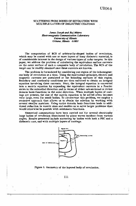
SCATTERING FROM BODIES OF REVOLUTION WITH MULTIPLE LAYERS OF DIELECTRIC COATINGS
James Joseph and Raj Mia.Ta Ekctromagnmc Communication. Laburatory
University of /lli.nois Urbana, Il1inou 61801
UB06-8
The computation of RCS of arbitrarily-shaped bodies of revolution. which may be coated with one or more layers of lossy dielectric material. is of considerable interest in the design of various types of radar targets. In this paper, we address the problem of calculating the equivalent surface currents on the outer surface of such a composite body of revolution. The RCS of the target can be readily obtained once these currents are known.
The problem is formulated by considering one region of the inhomogeneous body of revolution at a time. Using the equivalence principle, electric and magnetic currents are postulated at the bounding surfaces of this region. Boundary and continuity conditions are then enforced 1lo obtain an integral equation involving these currents. Next, the integral equation is converted into a matrix equation by expanding the equivalent currents in a Fourier series in the azimuthal direction and in terms of either sub-sectional or entire domain basis functions in the axial direction. When multiple layers of coatings are present, the size of the matrix equation to be solved often becomes very large, even for small bodies. To circumvent this problem, we employ a recursive approach that allows us to obtain the solution by working with several smaller matrices. Using entire domain basis functions leads to additional reduction in matrix sizes and ena.bles us to solve larger problems tllan would otherwise be possible with subdomain functions.
Numerical computations have been carried out for several electrically large bodies of revolution illuminated by plane waves incident from various angles. Results presented include scattering by bodies with both a PEC and a dielectric core, and with multiple layers of coatings.
Generating curvu
Figure 1. Geometry of the layered body of revolution.
111

UB06-9
LOW-FREQUENCY SCATTERING OF A PERFECTLY CONDUCTING SPHEROID SURROUNDED BY A HOMOGENEOUS MEDIUM
Tinglan Ji (Visiting Scholar from P.R.C.)
Electromagnetics Laboratory Electrical and Computer Engineering Department
University of Arizona Tucson, AZ 85721
A theoretical investigation of the low-frequency scattering from a perfectly conducting spheroid surrounded by a spheroidal homogeneous medium is presented. The spheroid is allowed to be general in size and eccentricity. The electromagnetic parameters £, µ and o of the coating 1 ayer are assumed to be constants.. An incident plane wave is considered to impinge on the spheroid at arbitrary angle of incidence with its major axis.
There have been several previous investigations of the scattering of the perfectly conducting spheroid, including analytical and numerical results. However, only the scattering problem of a spheroid without a coating medium was solved. It is the coating layer which makes the solution of the problem very complicated because of the nonorthogonality of the spheroidal angle functions for different parameters (e.g. see J.R. Wait, Antenna Theory, ed. by Collin and Zucker, Chap. 13, 1969). We cannot follow the usual technique and match, term by term, the two sides of the equations derived from the given boundary conditions to determine the unknown coefficients. In order to circumvent this difficulty, a quasistatic approximation method as proposed by A.F. Stevenson (J. Appl. Phys. 24, 1134-1142, 1953) has been used to obtain the explicit expressions of scattering fields. Some particular cases are also discussed.
112

UB06-10
ELECTROMAGNETIC FIELD PENETRATION INTO A DIELECTRIC FILLED CYLINDRICAL CAVITY OF ARBITRARY CROSS SECTION: TM CASE
Ercument Arvas Dept. of EE, Rochester Inst. of Tech., Rochester, NY 14623
A simple numerical solution is given for the problem of electromagnetic field coupling through a slot into a cylindrical cavity of arbitrary cross section. The cavity is assumed to be filled with a dielectric. The excitation is a plane electromagnetic wave with its electric field vector parallel to the axis of the cylinder. The surface equivalence principle and the method moments are used to obtain and numerically solve a set of coupled integral equtions for the equivalent surface currents which give the correct scattered field. The computed results are in excellent agreement with available published data. The figure below shows the magnitude of the total electric field at the center of a circular cavity.
6.
:;;- 4-.
~ lij fr=l.
2. ¢2=10·
D
113

114

MONDAY PM
JOINT SESSION JA03 ANTENNA MEASUREMENTS Chairman: M. Kanda, NBS
Room: Squires, Theatre Time: 1:30-4:40
1:40 FAR FIELD MEASUREMENTS OF 8-FOOT REFLECTOR ANTENNAS IN THE COMPACT RANGE AT THE OHIO STATE UNIVERSITY
See AP-S Digest
K. M. Lambert, R. C. Rudduck, T. H. Lee, The Ohio State University
2:00 A DUAL CHAMBER COMPACT RANGE CONFIGURATION See C. W. Pistorius, G. Clerici, University of Pretoria; D. Burnside, The Ohio State University
W. AP-S Digest
2: 20 OFFSET DUAL PARABOLIC CYLINDRICAL REFLECTORS See EMPLOYED AS A COMPACT RANGE AP-S
M. S. A Sanad, L. Shafai, University of Manitoba Dig.
2:40 A NOVEL METHOD FOR DETERMINING ANTENNA POLAR DIA- 116 GRAMS
W. K. Klemperer, National Bureau of Standards
3: 00 COFFEE BREAK
3:20 ERROR ESTIMATION OF A MICROWAVE HOLOGRAPH SYSTEM J. K. Hsiao, TASC
3:40 AN~ENNA APERTURE PHASE FROM FAR-FIELD MAGNITUDE M. 0. Milner, Wellington; P. H. Gardenier, R. H. T. Bates, University of Canterbury
4:00 ABSOLUTE GAIN MEASUREMENT BY THE IMAGE METHOD UNDER MISMATCHED CONDITION
R. Q. Lee, M. F. Baddour, NASA Lewis Research Center
4:20 FREQUENCY BEHAVIOR CHARACTERIZATION OF RECTANGULAR AND TAPERED MICROWAVE ANECHOIC CHAMBERS
M. C. Chandra Mouly, P. V. Sridevi, G. Mrudula, M. S. K Reddy, K. R. Rani, VRS Engineering College
115
See AP-S
117
See AP-S Dig.
118
Dig.

JA03-4
A NOVEL METHOD FOR DETERMINING ANTENNA POLAR DIAGRAMS
W.K. Klemperer Electromagnetic Fields Division National Bureau of Standards 325 Broadway Boulder, co 80303
Measuring the salient characteristics of a microwave antenna involves the tedious collection of E-plane and H-plane response data over angular and spatial increments as dictated by the sampling theorem. A straightforward modification of the usual holographic measurement technique (J.C Bennett et al., IEEE Trans. AP-24,3 295-303, 1976) can significantl~reduce the workload involved. The new method is particularly well-suited for precision antenna metrology in the controlled environment of a compact range.
116

JA03-6
ANTENNA APERTURE PHASE FROM FAR-FIELD MAGNITUDE
M.O. Milner, Post Office Headquarters, Wellington, New Zealand.
P.H. Gardenier, R.H.T. Bates, Department of Electrical and Electronic Engineering, Urtiversity Canterbury, Christchurch, New Zealand.
Regional and national earth station antennas used for satellite communications are usually so large that the only practicable way of measuring their far-field radiation patterns directly is by employing a satellite. Failµre of a pattern to meet any part of its specification is mainly due to misalignments in the antenna and feed structures. These misalignments can be deduced from the phase distribution in the aperture. Direct measurement of the phase (in either the aperture plane or the far-field) is difficult at the high frequencies used in satellite communications. However measurement of the magnitude of the far-field pattern is relatively straightforward,
We (P.H. Gardenier, C.A. Lim, D.G.H. Tan and R.H.T. Bates, Electronics Letters 22, 113-115, 1986) have previously modified the Gerchberg-Saxton algorithm (R.W. Gerchberg and w.o. Saxton, Optik 35, 237-246, 1972 - the algorithm was originally devised for electron microscopy), so that it can satisfactorily recover the aperture phase distribution from a measurement of the far-field magnitude and an estimate of the magnitude of the aperture field. The estimate we use is in fact the designed magnitude of this field. The algorithm consists of an iterative loop between the aperture plane and the far-field plane. By comparing the magnitude of the latest estimate of the far-field with the measured far-field magnitude, a measure of convergence can be calculated.
We present an computer generated example of an aperture field which has a 'designed' magnitude (incorporating edge taper and subreflector blockage) and constant phase. The 'actual' aperture field has phase terms which simulate a defocused antenna with a misaligned panel. In recognition of the fact that the magnitude of the actual aperture field will differ from its designed value, we have added noise to the designed magnitude to obtain a simulated 'actual' magnitude. Noise is added to the magnitude of the Fourier transform of the actual aperture field, to simulate a realistic 'measured' far-field magnitude. We then proceed to recover the 'actual' aperture phase from the 'designed' aperture magnitude and the 'measured' far-field magnitude. Inspection of the actual aperture phase indicates the degree to which the panel is misplaced, and the degree of defocus.
We assert that our algorithm should allow optimization of antenna performance, based on information provided by pattern measurement techniques which are now standard for satellite communications systems.
117
JA03-8
FREQUENCY BEHAVIOUR CHARACTERILATION OF RECTANGULAR AND TAPERED MICROWAVE ANECHOIC CHAMBERS
MC Chandra Mouly, PV Sridevi, G Mrudula, Iv1SK Reddy, KR Rani Electronics and Communication Engineering Department
VRS Engineering College, Vijayawada-520 006, India
With an increase in the frequency of operation, the reflectivity level at the centre of the quiet zone of a Microwave Anechoic Chamber gets affected on two counts. The absorber performance is better at higher frequencies, making their reflection coefficients smaller and thereby resulting in a lower reflected signal amplitude in the quiet zone. The source antenna radiation characteristics would also change due to lobing at higher frequencies. It is generally quoted that the RAC acts as a free space range at all frequencies while the TAC acts as a reflection range at lower frequencies and as a free space range at higher frequencies. Verification of this statement is the objective of this paper. The amplitude of the ray incident on the sidewall is assumed to be frequency invariant so as to isolate the effect of frequency on the chamber performance.
Since a comparative assessment of the Rectangular Anechoic Chamber {RAC) and the Tapered Anechoic Chamber (TAC) is desired, the single reflected ray concept has been pursued [MC Chandra Mouly, V Ranganadha Rao, C Raja Rao, NTC-83j. The amplitude of the total signal at the centre of the quiet zone is considered to be the performance index. The dimensions of RAC considered are 442 x 243 x 243 cm. The TAC also has similar dimensions except that the taper end is 43 cm and taper angle is 26.68°. The range length in either case is 290 cm. The quiet zone is a 20 cm cubic volume. VHP-NRL-8 absorbers are presumed to line the inner surfaces. The source horn dimensions in terms of wavelength are l.065 and 0.805 [MC Chandra Mouly, N Vijaya Vani, N Rukmini Devi, K Sujata, IEEE AP-S/URSI, 18, 1985).
The total signal at the centre of the quiet zone, due to the direct and one reflected ray, is computed for both RAC and TAC over a frequency range of 4·to 24 GHz. It is observed that the TAC exhibits a damped type ripple that settles down at a steady value for frequencies higher than 7 GHz. In contrast, the RAC exhibits a fairly steady value of the total signal over the entire frequency band. Since in a free space range the total signal received will be constant, it can be concluded from the above that the RAC acts as a free space range at all frequencies. ln a TAC the ripple is predominant at lower frequencies. So it is visualized that its action is tantamount to that of a reflection range. This provides a proof of the statement made above.
118
TUESDAY AM
URS! SESSION UB07 GUIDING STRUCTURES & RESONATORS
Chairman: F. J. Tischer, NC State Univ Room: CEC, Meeting Room B Time: 8:30-12:00
8:40 COMPLETE PROPAGATION-MODE SPECTRUM OF MICROSTRIP 120 GUIDING STUCTURES
M. J. Cloud, D. P. Nyquist, Michigan State University
9:00 EXPERIMENTAL VERIFICATION OF ANALYTICAL STUDIES 121 ON SCATTERING BY OBSTACLES ALONG SURFACE WAV.EGUIDES
T. M. Lowe, D. P. Nyquist, Michigan State University
9:20 CALCULATION OF GUIDED MODES OF ARBITRARILY INHO- 122 MOGENEOUS OPTICAL FIBER USING THE POWER METHOD AND THE FAST FOURIER TRANSFORM
C. Su, National Tsignhua University
9:40 PROPAGATION CHARACTERISTICS IN COAXIAL WAVEGUIDE 123 FILLED WITH WEAKLY MAGNETIZED FERRITE
Y. Kotsuka, Tokai University
10:00 THE COUPLING OF INCIDENT FIELDS TO ELECTRICALLY- 124 LONG MULTICONDUCTOR TRANSMISSION LINES A. T. Adams, J. Perini, Syracuse University
1 o: 20 COFFEE BREAK
10:40 SHORT CIRCUITED H-PLANE SEPTUMS IN RECTANGULAR 125 WAVEGUIDES J. M. Rebollar, ETSI Telecomunicacion
11 :00 CASCADED TRIFURCATED JUNCTIONS IN RECTANGULAR 126 WAVEGUIDE J. Esteban, J. M. Rebollar, ETSI Telecomunicacion
11 :20 THE ELECTROMAGNETIC FIELD OF A THREE-LAYER SPHER- 127 ICAL RESONATOR WITH ANISOTROPIC MATERIAL I. Wolff, Universitat Duisburg
11:40 Loss CALCULATION IN SYMMETRICALLY SPHERICAL WITH 128 CIRCULAR APERTURE UNSTABLE OPTICAL RESONATORS USING DIFFERENT TECHNIQUES
M. H. Rahnavard, H. Zare-Moodi, Shiraz University
119

UB07-1
COMPLETE PROPAGATION-MODE SPECTRUM OF MICROSTRIP GUIDING STRUCTURES
M.J. Cloud and D.P. Nyquist Department of Electrical Engineering
and Systems Science B.C. Drachman, Department of Mathematics
Michigan State University East Lansing, Michigan 48824
Results of investigating the propagation-mode spectrum for longitudinally-invariant microstrip systems are presented. The influence of a layered conductor/film/cover background environment is rigorously accounted for.
Surface current eigenmodes K(1) are solutions of a homogeneous electric field integral equation + (EFIE). The EFIE, which is enforced at all points r on the conducting microstrip surface S, may be stated as
where k is the wavenumber in the c~ver medium, i is a unit tangent vector to S, and G(t,r') is a Hertz potential Green's dyad. This dyad depends explicitly upon the thickness and permittivity of the film layer. Often neglected transversely-flowing surface currents are retained in the model through a coupled integral equation approach, and are quantified along with the longitudinal components.
Emphasis is placed on leaky microstrip modes associated with transversely propagating surface waves of the background environment. Numerical solution is performed by Galerkin·• s method using entire-domain basis functions.
120

UB07-2
EXPERIMENTAL VERIFICATION OF ANALYTICAL STUDIES ON SCATTERING BY OBSTACLES ALONG SURFACE WAVEGUIDES
Timothy M. Lowe and Dennis P. Nyquist
Department of El.ectrical Engineering and Systems Science Michigan State University, East Lansing, Michigan 48824
Sattering of TEo principle-mode surface waves by slice discontinuities along a symmetric slab dielectric waveguide are studied. Experimental measurements of reflection/transmission coefficients and discontinuity fields implemented at millimeter wavelengths are compared with theoretical predictions. Measurements accomplished with V-Band mm-wave apparatus and analytical results based upon electric field integral equation (EFIE) description of discontinuity region.
The EFIE for Ey(x,z) induced in the discontinuity region is:
jt.n2Ko f.tf t Ey(x,z) - Zo Ey(x',z')Gyy(x,z[x',z')dx'dz'
-.t -t -js0z
E0ey0(x)e •.• for all fx[<t, [zj<.t.
Where .t is the half length, tis the half thickness and 6n2 is the squared refractive index contrast. Kernal Gyy is represented by an expansion in the complete propagation mode spectrum of the guiding region. TE surface waves are guided by a dielectric slab inserted between two parallel aluminum planes, which implements an infinite image sequence to simulate an infinite planar slab. Fields are probed by a monopole antenna inserted through a series of holes drilled in the top plane.
Results presented are of varying discontinuity dimensions and index contrast. Limitations on analytical and experimental methods are identified.
121

UB07-3
CALCULATION OF GUIDED MJDES OF ARBITRARILY INH<MXl:ENEOUS OPl'ICAL FIBER
USING THE POWER METIIOD AND THE FAST FOURIER TRANSFORM
Ching-Chuan Su Department of Electrical Engineering
National Tsinghua University Hsinchu, Taiwan ROC
To find prop-1gat i.on characteristics of guided modes of an inbnm<lgPneous optical fiber of arbitrary transverse shape, a sc:alar· f:ield integral equation is formulated as
1'(x,y) - k/ JI [e(x' ,Y' )- e1
J G("lp) 1'(x• ,Y') dx'dy' = O.
Here, the integration covers those areas "'here €. ( x • , ~· • ) -E.1
;tO, 1'
denoi;es a transverse component. fiel.d in rectangular coordinates (Ex' EY, Hx' or Hy)' k0 is the free-space propagation constant, e. 1 is the relative permittivity of the cladding, e. is the relative permittivity distribution of the core, G denotes the
2 2 2 two-dimensional Green's function, "I =/J -k
0 e.
1 (~0), /J is the
propagation constant. in a'Cial direct.ion, and 2 2 2 p =(x-x•) +(y-y•) ,
The integral equation can be treated numerically, using pulse-function expansion and point-matching. It. comes from two facts that. the proposed met.hod is quite efficient.. First., employing the approach of integral equation, the propagation problem is reduced to a standard eigenvalue problem, where the lower-order modes correspond to the larger eigenvalues, Hence, the eigenproblem can be manipulated efficiently by the power met.hod. Furthermore, the major computation in the associated power met.hod is of a form of convolution, which in turn can be performed using the fast. Fourier transform (FFT). Numerical results of the dispersion curves and field distributions of some guided modes of an elliptical fiber will be presented,
122

UB07-4
PROPAGATION CHARACTERISTICS IN COAXIAL WAVEGUIDE FILLED WITH WEAKLY MAGNETIZED FERRITE
Youji KOTSUKA Department of Telecommunications Engineering, Tokai University
1117, Kitakaname, Hiratsuka City, JAPAN
To cultivate new applications of polycrystaline ferrite to microwave devices, propagation. characteristics in coaxial waveguides filled with weakly magnetized ferrite are theoretically and empirically investigated in the frequency range from 0.5 to 4.0 GHz. Static magnetic field Hdc is applied externally to the ferrite in the direction of propagation. As for the strength of the applied static magnetic field, the following. two cases are researched. One is concerned with the case of a low but fully saturated d-c field; the other is the low unsaturated field shown in Fig. I. Those propagation characteristics, as well as their permeability, still are not well known.
Hoc=O :- 10·11 D-C FIElD , HIGH D-C FIELD
~;;;;;::;;5L;,:;,:,;w;,;,$f":Jl§t.:,,,is§.i'.;£',~~ - - - ),, !<c-UNSATURATED~ SATURATED REGION~~~~-: REGION :
Fig. I Explanation of the region of d-c field investigated
First, in the case saturated by a low d-c field, the following matters are investigated by computer-aided analysis of the rigorous characteristic equation previously presented (Y. Kotsuka, Proc. URSI Int. Symp., 479-482, 1983). (I) The matter of deviation in applying Suh! & Walker's approximate expres~ion (H. Suh! et al., BSTJ, 3, 1168-1194, 1954) to the coaxial waveguide is investigated in detail. As the result, it was concluded that Suh! & Walker's applicable limit was at most the size of a 20D coaxial waveguide, which is £/'ri. within about a 5% error, where Q is the difference between radius of the outer conductor and the inner one, taking the value of 0.564 [cm). A is the wavelength. (2) As for propagation characteristics, relation between the effective permeability and the propagation constant is visually clarified together with 41rMs and LiH by conformal mapping.
Second, in the unsaturated d-c field, propagation -characteristics were discussed from the standpoint of scaler permeability. (I) In the experimental expression of frequency dispersion equation of permeability µr without Hdc (Y. Naito, Trans. IECEJ, 2, 1973), as to the unsaturated case, it is suggested that the value of Kf1 in Naito's expression be extended from 10 to 16 GHz by a low static magnetic field.
Finally, propagation characteristics, not only in the low field but also in the zero field, are summarized. Through the present research mentioned above, ·it became clear that the propagation characteristics, including the zero d-c field, can be understood from the standpoint of permeability only.
123

UB07-5
THE COUPLING OF INCIDENT FIELDS TO ELECTRICALLY-LONG MULTICONDUCTOR TRANSMISSION LINES
A. T. Adams. and Jose Perini Department of Electrical and Computer Engineering
Syracuse University, Syracuse, NY 13210
The treatment of electromagnetic coupling to electricallylong transmission lines by numerical methods is limited by the number of unknowns. Thus as frequency increases problems may become intractable. A method has been developed which permits one to treat multiconductor transmission lines of shorter length (at specified frequency f
0) and derive thereby bounds to the behavior
for longer lengths at frequency f 0 .
·The multiconductor transmission is treated as an N-port antenna system, the ports being the points on the transmission line at which one is interested in induced currents or voltages. One may thus reduce the problem to either a one-port or an N-port for a particular problem, depending on whether loads are specified, The equivalent circuits of the one-port or N-port receiving system is then used to bound the values of induced current or voltage at the points of interest. The equivalent circuit of the one-port involves the open-circuit voltage of the one-port receiving antenna, and the impedance of the one-port when operated as a transmitter. The equivalent circuit of the N-port receiving system is derived; it involves the open-circuit voltages at each port when all ports are simultaneously open-circuited, and the N-port parameters, such as the open-circuit impedance parameters, of the N-port system.
It has long been well known that the impedance of a dipole antenna, when plotted as a function of dipole length, quickly spirals in to a shape which is approximately a circle in the complex plane; maximum and minimum values of impedance may thus be bounded as antenna length increases. These same properties are maintained for a wide variety of antennas including multiconductor transmission lines. Furthermore the properties hold for mutual as well as self impedances, These characteristics permit one to bound the behavior of the longer transmission line from the known (calculated or measured) behavior of the shorter transmission line.
124

UB07-6
SHORT-CIRCUITED H-PLANE SEPTUMS IN RECTANGULAR l~A\/EGU I DES
,] . M. 1=.:ebol la,-Grupo de Electromagnetismo Aplicado
ETSI Telecomunicacion. U.P.M. 28040-Madrid. ESPA~A
The Generalized Scattering Matrix of generalized 2-port discontinuity concept and the modal field expansion technique (R.R.Mansour, R.H.MacPhie, IEEE T1·-;;-.r1s Mic1-rnAJ Theory T,;echn, MTT-33,830-835, 1985). is applied to the analysis of short-circuited H-plane s,;;ptums. It is proved that its behaviour is similar to the shortcircuited stub placed in series with the equivalent transmission line of the fundamental mode.
Two structures (figures I,II> combinations of two short-circuited H-plane septums are considered. The electromagnetic behaviour of the structure I is similar to the superposition of two septums, however the structure II presents a response strongly dependent on distance W between septums. A response similar to that structure I is obtained for high W values. If distance W decreases the interaction between the generated higher order modes in the septums is increased and the response changes substantially. When Wis low enough the structure II behaves as a reaction cavitie.
These results show that the presented structures can be used as basic elements to design stopband waveguide filters.
f~ l.
.8
.6
.4
B I
(I)
j_._ _______ __.,
(II)
.2
9. 10. 11. 12. Frequeacyd.O!fz }:-
A=22.86, B=l0.16, B1
=2,06
L1=11. , L
2=9. Dimensions
in mm. T=T
1=T
2=0.1
125

UB07-7
CASCADED TRIFURCATED JUNCTIONS IN RECTANGULAR WAVEGUIDE
Authors: J. Esteban, J. M. Rebollar Grupo de Electromagnetismo Aplicado.
E.T.S.I.de Telecomunicaci6n. 28040-Madrid.
The Generalized Scattering Matrix of generalizated 2-port discontinuity toncept <R.R.Mansour, R.H.MacPhie, IEEE Trans. on Mierow. Theory and Techn., MTT-33, pp. 830-835, 19851 and the modal field expansion technique is applied to the analysis of cascaded trifurc~ted junctions in rectangular waveguide.
The structure {figure 1) has two transversal di~continuities and it must be noted that not only the z=O but also the z=L discontinuity is regarded as a 2-port problem, although it is a 3-to-5 waveguide junction.
The length L can be used to improve the ratios between transmitted amplitudes to the output waveguides. Numerical results, which have not shown relative convergence problems, are presented (figure 2).
This simple structure has direct aplication to power divider design.
z=O z=L z .,,,
I A2
tl I
I A3
.A t2,
A4 1 I
t3 I ' A5
t4, A6
Transmitted amplitudes
0. 5,------
5. 10. 15. 20. 25.
126
Figure 1. Structure.
A2
Figure 2.
TE10
mode incident
with unit amplitude.
Al=ll2. mm.
A2=A3=A4=A5=A6=22.86
L(mm) tl=t2=t3=t4=0.l

UB07-8
THE ELECTROMAGNETIC FIELD OF A THREE-LAYER SPHERICAL RESONATOR WITH ANISOTROPIC MATERIAL
Inga Wolff Department of Electrical Engng. and Sonderforschungsbereich 254
Universitat Duisburg, D-4100 Duisburg, W.-Germany
The electromagnetic field and the eigenvalue equation of a three layer spherical resonator with arbitrary material parameters and an anisotropic dielectric insert is described. The possible modes of the resonator, the field distributions, the Q-factors and applications will be discussed.
Spherical isotropic resonators have been discussed in the literature since nearly 80 years. Primarily the famous work of Debye (Annalen d. Phys., vol.30, pp. 57-136, 1909) must be mentioned here, because many theoretical problems of isotropic spherical resonators have been solved already in this classical work.
Spherical resonators for many reasons still are interesting e.g. in microwave integrated circuit techniques or in material parameter measurement techniques.:
The spherical resonator has the highest Q-factor of all possible resonator geometries,
- Spherical resonators can be produced easily, - The excitation of the spherical resonator can be easily done, - The spherical isotropic resonator has threefold degenerated re-
sonances, which split up in the cae of an anisotropic resonator; this can be used in material parameter measurement techniques.
The electromagnetic fields of a three-layer spherical resonator, where the inner sphere can be uniaxially anisotropic will be described. The material parameters of all three layers may be arbitrary including dielectric losses and conductor losses. The formulation of the electromagnetic fields is rigorous. Using this computer model spherical resonators like: 1) The free dielectric sphere with one or two dielectric layers, 2) the free conducting sphere, 3) the spherical homogeneous cavity, 4) the spherical cavity with an inner conducting sphere, and 5) the spherical cavity with an inner (isotropic or anisotropic) dielectric sphere can be analyzed. For the first time the exact convergence of the resonant frequencies of a closed spherical cavity with an inner dielectric sphere into that of a free sphere can be studied.
In the case that the inner dielectric sphere is uniaxially anisotropic, the modes which are independent of the azimuthal angle will be studied. It can be shown that in this case E- and H-modes are still existent seperately. The electromagnetic fields of the modes can be described by a series of coupled E- and H-modes of the isotropic spherical resonator. The mode coupling and the resulting split up of the resonant frequencies will be discussed.
It will be shown, how the spherical cavity with an inner sphere can be used to measure the material parameters of conducting and dielectric, isotropic and anisotropic materials very accurately.
127

UB07-9
LOSS CALCULATION IN SYMMETRICALLY SPHERICAL WITH CIRCULAR APERTURE UNSTABLE OPTICAL RESONATORS USING DIFFERENT TECHNIQUES
M. H. RAHNAVARD, H. ZARE-MOODI Electrical Engineering Department
Shiraz University, Shiraz, Iran Telephone Number: Iran, Shiraz 34064-2712
Unstable Optical resonator is used in medium and high power laser. In stable resonator when Fresnel number is greater than 0.5 all of the energy is not absorbed by 1st mode but energy is absorbed in higher order modes. In unstable resonator with proper gain it is possible to have mode with lowest power loss and th1s mode will absorbe most of the energy from the laser material and it is possible to have optical resonator with smaller length. For this reason power loss calculation is important in unstable optical resonators.
At first Fox and Li calculated power loss in infinite strip cylinderical and spherical resonators with circular aperature for Fresnel number greater than 10 by scalar theory of diffraction using iterative method (Fox, A. G. and Li, T. H. 1964. Quantum Electronic Ill, 8, 1262). By using geometrical optics Siegman calcul_ated power loss in optical resonators for large Fresnel number (Siegman, A. E. 1965. Proc. IEEE. 53, 277). Sanderson and Striefer calculated power loss by Gaussian Quadrature and Cornu spiral methods (Sanderson, R. L., and Streifer, W. 1969. Appl. Opt. 8, 2129.). In the first method the integral is converted to a matrix. Using QRmethod eigenvalue and eigenvector of the matrix is evaluated. Eigenvectors are electric field modes and power loss in each mode is equal to one minus absolute value of the eigenvalue of that mode. Siegman and Miller found eigenvalues for spherical resona-tor with circular aperture with Fresnel number greater than 13 using Prony's method (Siegman, A.E. and Miller, H. Y. 1970. Appl. Opt. 9, 2729). Santana and Felson calculated eigenvalue using waveguide tiieory (Santana, C. and Felsen, L, B. 1976. Appl. Opt. 9, 1470.).
As Fresnel number gets larger resulting series from the integral has more elements. The number of elements in the series is usually between 6 to 10 times the Fresnel number (Siegman, A. E. and Miller, H. Y. 1970. Appl. Opt. 9, 2729.). So power loss evaluation in optical resonators with Fresnel number greater than 10 takes ,t long time. Except Santana and Felson (Santana, C. and Felsen, L· B. 1976. Appl. Opt. 9, 1470.) all of the works which is done based on scalar theory of diffraction. In this paper physical optics in exact form and with Fresnel approximation, scalar theory of diffraction without approximantion, geometrical theory of diffraction and physical theory of diffraction ar?. used in analyzing and power loss calcuation of symmetrically spherical with circular apperture unstable resonators.
128

TUESDAY AM
JOINT SESSION JB06 PROPAGATION MEASUREMENTS
Chairman: D. V. Rogers, COMSAT Labs Room: CEC, Meeting Room F Time: 8:30-11:40
8:40 JOINT-PATH AVAILABILITY FOR NARROWBAND HF SKY- 130 WAVES
L. G. Abraham, B. J. Turner, K. H. Wickwire, The MITRE Corporation
9:00 RADIO WAVE PROPAGATION CHARACTERISTICS IN PRECI- 131 PITATION AS DETERMINED BY RADAR
Y. M. Antar, National Research Council of Canada
9:20 CROSS-POLARIZATION DISCRIMINATION MEASUREMENT AT See THE CS-2 EXPERIMENTAL EARTH STATION AP-S
Y. Maekawa, N. S. Chang, A. Miyazaki, Osaka Electro- Dig. Communication University; T. Segawa, Computer Service Corp.
9: 40 Low ALTITUDE RADAR PROPAGATION MEASUREMENTS OVER 132 WATER
B. H. Cantrell, G. Linde, J. Wilson, Naval Research Laboratory
10:00 COFFEE BREAK
10:20 VERY Low-LEVEL PROPAGATION STUDIES USING SUPERRESOLUTION AND SYNTHETIC-APERTURE ANTENNA TECHNIQUES J. Litva, J. P. Reilly, McMaster University; Communications Research Centre
N. R. Fines,
10:40 ANGLE OF ARRIVAL MEASUREMENTS OF RADIO WAVES IN A LAND TACTICAL ENVIRONMENT
11 :00
R. Middelkoop, FEL-TNO
MULTIPLE-ANTENNA-DIVERSITY RECEPTX.ON
H. M. Lindenmeier, L. M. Reiter, wehr Munchen
FOR FM
Universitat
CAR RADIO
Der Bundes-
See AP-S Dig.
See AP-S Dig.
See AP-S Dig.
11:20 PROPAGATION STUDIES ON DOUBLE KNIFE-EDGE DIFFRAC- See TION PATH AP-S
M. N. Roy, Jadavpur University; R. K. Tewari, B. S. Jas- Dig. sal, Defence Electronics Applications Laboratory
129
JB06-1
JOINT-PATH AVAILABILITY FOR NARROWBAND HF SKYWAVES
by L.G. Abraham, B.J. Turner and K.H. Wickwire The MITRE Corporation
Narrowband (3 KHz) skywave data has been collected at Bedford (MA) from HF sounding transmissions of three remote stations for more than one year. This talk will assess the degree of correlation of bit error rate that exists between signals arriving over the three different paths and how such information can be used to enhance communication.
The sounding experiment consisted of basic multi-tone FSK signals (I· out of 8 possible tones) transmitted in fixed 160 msec long sequences of 20 consecutive tones. Each tone was 8 msec long and was separated by 250 Hz from its neighbors. Some 20 different carrier frequencies were employed which were spread unevenly across the HF band. Every 30 minutes the 3 stations took turns (one per second) sending the basic FSK signal so that all 20 HF carrier frequencies were covered. The 3 remote stations were located at Pope Air Force Base (AFB) (NC), Homestead AFB (FL) and Offutt AFB (NC). The nominal path lengths from Bedford (MA) were 1000, 2000 and 2000 km, respectively.
At the Bedford (MA) site a decision was made as to which tone (out of the 8 possible) was received in each 8 msec time slot. These decisions were compared to the known sequence and a separate error rate recorded in each 10 minute interval for each one of the 20 HF carrier frequencies. A binary decision on path availability was made using a fixed threshold of error rate. The path was said to be available in a 10 minute interval if any one of the corresponding 20 different error rates fell below the fixed threshold.
Path availability will be calculated as a function of time of day, season and location of the transmission site. Multipath availability will then be defined and assessed for various situations in which the station at Bedford (MA) serves as a destinat~on or as a relay point. These situations will be described along with the results of the corresponding assessments of multipath availability.
130

RADIO WAVE PROPAGATION CHARACTERISTICS IN PRECIPITATION AS DETERMINED BY RADAR
Y.M.M. Antar Division of Electrical Engineering
National Research Council of Canada Ottawa, Ontario CANADA
KlA OR8
JB06-2
At centimeter wavelengths,attenuation,differential attenuation a.nd differential phase shift due to atmospheric precipitation can have substantial adverse effects on the wave propagation phenomena. These effects can result in degrading the performance of communication links and may also create uncertainty about radars capability in particle identification. There is considerable interest in developing new experimental, techniques to better understand these effects and hence devise improved models.
The NRCC polarization diversity radars in Ottawa, enable the exploitation of the information content of the partially polarized backscatter, as expressed by the elements of the coherency matrix which represent the system measurables. From this information, the differential attenuation and the differential phase shift upon propagation·, have been determined using circular polarization. Also an estimate of the attenuation can sometimes be obtained from radar data. Recently radar measurements have been conducted at linear polarization, thus providing additional information in form of the coherency matrix elements for linear polarization vector base. Furthermore, differential propagation effects due to anistropy of the media affect some of the measured paramaters at circular and linear polarization differently. Hence, combining information from measurements at linear polarization with those obtained from sequential measurements performed on the same storm at circular polarization will provide new important information. This will help the particle identification process and contribute toward the development of better models. In this paper we study propagation effects at linear and circular polarization. Results from radar measurements at 9.6 GHZ, performed at both circular and linear polarization, and analysis will be presented.
131

JB06-4
LOW ALTITUDE RADAR PROPAGATION MEASUREMENTS OVER WATER
B. Cantrell, G. Linde, and Jon Wilson Naval Research Laboratory 4555 Overlook Avenue, S.W.
Washington, D.C. 20475-5000 (202) 767-2573
Measurements of the two-way propagation characteristics over water at low altitudes were made using an L-band radar and a sphere hung from an aerostat. The height of the sphere was varied and the signal strength of the radar echo was measured. Signal strengths versus altitude plots were made for frequencies of 901,941, 1264, and 1300 MHz and for both vertical and horizontal polarization. Radiosondes were launched and pressure, humidity, and temperature were measured as it ascended. From this data, the index of refraction and modified index of refraction was measured as a function of altitude. Measurements were made on two different days at ranges of 11 and 19 nautical miles. The measurements were compared to theoretical results based on a standard atmosphere using a (4/3) earth's radius. The measurements and theoretical results did not completely agree. The differences are probably due to the nonstandard atmospheric conditions which were measured with the radiosonde.
132

TUESDAY AM
JOINT SESSION JB07 IMPACT OF COMPUTER ARCHITECTURE & SUPERCOMPUTERS
Chairman: W. R. Stone, IRT Corp Organizer: Dr. W. R. Stone
Room: CEC, Auditorium Time: 8:30-12:00
8:40 SOME OBSERVATIONS ON THE IMPACT OF EMERGING COM- 134 PUTER ARCHITECTURES ON THE FORMULATION OF ELEC-TROMAGNETICS PROBLEMS
R. A. Whitaker, McDonnel Douglas Aerospace Information Systems; L. W. Pearson, McDonnell Douglas Research Laboratories
9: 00 LARGE MATRIX PROBLEMS IN THE COMPUTATION OF ELEC- See TROMAGNETIC FIELDS . AP-S J. L. Fath, A. J. Terzuoli Jr, Air Force Institute of Dig. Technology
9:20 COMPUTER ARCHITECTURE IMPLICATIONS OF THE NUMERI- See CAL SOLUTION FOR THE ELECTROMAGNETIC FIELD OF AN AP-S ARBITRARY CURRENT SOURCE Dig. J. L. Strauss, B. A. Hoyt, J. W. DeGroat, A. J. Terzuoli, A. V. Lair, Air Force Institute of Technology
9: 40 COMPUTER TECHNOLOGY ISSUES AFFECTING LARGE-SCALE See ELECTROMAGNETIC WAVE SCATTERING AND INTERACTION AP-S CODES Dig.
A. Taflove, Northwestern University; K. R. Umashankar, University of Illinois at Chicago
10:00 How TO EXPLOIT COMMON I/0 AND ARITHMETIC OPER- See ATION ARCHITECTURAL RELATIONSHIPS FOR ELECTROMAG- AP-S NETIC COMPUTATIONS Dig.
W. R. Stone, IRT Corporation
10:20 PANEL DISCUSSION
133

JB07-1
SOME OBSERVATIONS ON THE IMPACT OF EMERGING COMPUTER ARCHITECTURES ON THE FORMULATION
OF ELECTROMAGNETICS PROBLEMS
R. A. Whitaker, McDonnell Douglas Aerospace Information Systems L. w. Pearson, McDonnell Douglas Research Laboratories
P. O. Box 516, Saint Louis, MO 63166
In this pr_esentation we discuc;s the way in which presently emerging computer architectures bear on solution approaches in electromagnetics problems. In one way or another, all so-called supercomputers employ a configuration of parallel computational units in order to achieve high computational speed. Until recently, the so-called single-program/multiple-data (SPMD) architecture was pervasive. More recently, a multiplicity of different a~chitectures in which parallelism is exploited in various ways has emerged, driven by technological a,1 vctnces in mi crocircui try and by the fact that supercomputer clock speeds have neared physi.ccJ.l limits. Generally speaking, this parallelism takes on a new format: namely, multiple-program/multiple-data (MPMD) architecture.
One who would exploit MPMD archi tectt1res is posed with a perplexing variety of parcJ.llel configurations, ranging from a coupling of a few very powerful processors (e.g., Cray XMP multiprocessors and Cray 2) to large numbers of "computer-on-achip" processors (e.g., the Intel Hypercube). The computer industry is engaged in computer-language enhancement to make this hardware technology accessible to scientific users and to make res,llting software portable from one machine to another. It is not clear that these goals have straightforward solutions so that they can be met in a timely fashion, leaving the user to match algorithms and target machines.
SPMD processors are intrinsically suited to the formulation of physical problems from first principles as, for example, in finite-element or finite-difference algorithms. In such formulations, each processor operates in a virtually identical fashion on datcJ. that differ only by the parameters associated with different grid points. MPMD processors provide the scientific user with the ability to have a single system exercise drastically different algorithms simultaneously or to simultaneously perform similar computations with different parameters when algorithm time is strongly parameter sensitive. An ex~nple of a multiplealgorithm computation is the Unimoment method [K.K. Mei, IEEE Trans. Ant~nnas Propagat., AP-22(6), 760], which is a hybrid between the moment method and a frequency domain finite-element method. An example of a parameter-sensitive algori'thm is a spectral domain calculation involving Bessel functions with. drastically different argument and/or order.
134
---- --~--------
TUESDAY AM
URS! SESSION UB08 ANTENNAS II
Chairman: L. Peters, Ohio State Univ Room: Squires, Rehearsal Room Time: 8:30-12:00
8:40 ARRAY ANTENNA SYNTHESIS INCLUDING ELEMENT AND 136 FEED COUPLING
K. Takamizawa, W. L. Stutzman, Virginia Polytechnic Institute & State University
9: 00 ON THE DYADIC GREENS FUNCTION FOR AN INFINITE 137 PERIODIC ARRAY OF ARBITRARILY ORIENTED DIPOLE IN A MULTI-LAYERED MEDIA S. Barkeshli, P. H. Pathak, The Ohio State University
9:20 POCKLINGTON-TYPE AND HALLEN-TYPE !NTE- 138 GRAL EQUATIONS FOR ELECTROMAGNETICALLY COUPLED WIRES AND SLOTS OF ARBITRARY CONFIGUATION
H. Nakano, Hosei University; S. R. Kerner, N. G. Alexopoulos, University of California
9:40 A NOVEL PHASED ARRAY OF LEAKY-WAVE NRD GUIDES 139 A. A. Oliner, Polytechnic University; X. Shanjia, Univer-sity of Science & Technology of China
10:00 ANALYSIS OF GRATING ANTENNA WITH FINITE WIDTH 140 Z. S. Wu, Z. M. Lu, S. T. Peng, New York Institute of Technology; F. K. Schwering, US Army Communica.tion Electronics Command
10: 20 COFFEE BREAK
10:40 PHASED ARRAYS FOR MULTIBEAM A. I. Zaghloul, S. mann, INTELSAT
VERSUS REFLECTOR SYSTEMS SATELLITE APPLICATIONS
Siddiqi, COMSAT Laboratories; W. Borne-
141
11:00 SQUARE HELICAL ANTENNA WITH A DIELECTRIC CORE 142 J. P. Casey, Naval Underwater Systems Center; R. Bansal, The University of Connecticut
11: 20 LENS ANTENNAS FOR PATTERN SYNTHESIS AND WIDE- 143 ANGLE SCAN
W. P. Shillue, C. J. Sletten, GTE
11: 40 THE RADIATION RESISTANCE OF LOOP ANTENNAS WITH 144 COSINUSOIDAL CURRENT DISTRIBUTION M.A. Sultan, Corvallis, Oregon
135

UBOS-1
ARRAY ANTENNA SYNTHESIS INCLUDING ELEMENT AND FEED COUPLING
K. Takamizawa W. L. Stutzman
Virginia Polytechnic Institute and State University Electrical Engineering Department Satellite Communications Group
Blacksburg, VA 24061
Precise radiation pattern control for an array antenna requires precise control over array element excitations. One application is that of low side lobe patterns. patterns. Classical synthesis methods for the desired pattern may not be realized in practice due to coupling effects. Coupling occurs in two forms: the mutual coupling between array clements and the coupling introduced by the feed networks. Ideally one could account for such coupling within the array architecture during the design process and alter the feed network parameters to adjust for such coupling. Unfortunately, this is a nonlinear problem requiring special solution techniques.
In this paper we report on solution techniques for determining feed network parameter values that compensate for antenna-feed network coupling. Scattering parameter representation of the antenna array and feed networks are used. Examples of various array configurations for microstrip antenna arrays are included.
136

UB08-2
ON THE DYADIC GREEN'S FUNCTION FOR AN INFINITE PERIODIC ARRAY OF ARBITRARILY ORIENTED DIPOLE IN A MULTI-LAYERED MEDIA
SINA BARKESHLI and P.H. PATHAK The Ohio State University ElectroScience Laboratory
1320 Kinnear Road Columbus, Ohio 43212
The dyadic Green's function of periodic structure in multi-layered media has an application in the analysis of the frequency selective surfaces (FSS), guided wave structures, and large phased arrays. The characteristic of an arbitrary oriented piecewise linear element in an infinite array has been extensively studied by Munk and his group (B .A. Munk and G.A. Ru rre 11, IEEE Trans. Antennas and Propagation, AP-27, pp. 331-343, 1979) and (B.A. Munk and T.W. Kornbau, Electromagnetics 5: pp. 349-373, 1985). Their theory is based on the consideration of multiple reflections of an infinite number of plane waves traveling in different directions in the stratified media, resulting from the infinite periodic array. In this work it will be shown how the systematic use of the distribution theory and formulation of the dyadic Green's function of the multi-layered media can lead to the dyadic Green's function for an infinite periodic structure embedded in a stratified media. The relation between the two dyadic Green's functions will be discussed, and as an example the characteristics of an infinite and finite array of dipoles embedded in a two layered media will be compared.
137

UBOS-3
POCKLINGTON-TYPE AND HALLEN-TYPE INTEGRAL EQUATIONS FOR ELECTROMAGNETICALLY COUPLED WIRES AND SLOTS
OF ARBITRARY CONFIGURATION
H. Nakano College of Engineering, Hosei University
Koganei-City, Tokyo, Japan 184
S. R. Kerner and N. G. Alexopoulos University of California at Los Angeles
California, USA 90024
. The formulation is made for the following situation: An incident field (En Jfn) penetrates through a narrow slot in a planar conducting screen, and excites a thin wire behind the screen. The screen is assumed to be perfectly conducting and vanishingly thin, and of infinite extent. It should be noted that the slot and wire are arbitrarily bent; the more specialized problem of linear slots and wires has already been fully addressed by other authors. The final expressions in this paper are derived in the form of both Pocklington-type and Hallen-type integral equations.
In .the Pocklington-type equation, the electric current on the wire and the magnetic current on the slot are expanded using sinusoidal basis functions. The electric and magnetic fields are reduced to simple algebraic expressions, leading to an easier treatment by the moment method.
A simplification is also made for the Hallen-type equation: the kernels are reduced to a form which contains neither derivatives nor integrals. In addition, the associated scalar potentials for the wire and slot of arbitrary configuration are derived in the form of an integral equation with a simplified kernel. This facilitates an analysis of junction problems, that is, wires or slots joined at a point.
The numerical solution of a Pocklington-type equation with piecewise sinusoidal testing functions may be regarded as being identical to that of the point-matched Hallen's equation (D. R. Wilton and C. M. Butler, IEEE AP-24, 83-86, 1976). The generalized formulation presented here allows treatment of special cases such as slot-only or wire-only problems. Numerical results for these cases and the more complex situation of the slot and wire, based on the Pocklington-type equation with piecewise sinusoidal testing functions and the point-matched Hallen-type equation, will also be described during the presentation.
138

A NOVEL PHASED ARRAY OF LEAKY-WAVE NRD GUIDES
Arthur A. Oliner and Xu Shanjia* Polytechnic University, Brooklyn, New York
UB08-4
A novel linear phased array of parallel leaky-wave nonradiative dielectric (NRD) guides that furnishes a two-dimensional scan is.proposed and analyzed. Scanning in one plane (elevation, but only in the forward quadrant) is provided by a frequency scan or an electronic scan of the leakywave NRD line sources, whereas scanning in the other plane (azimuth) is obtained in the usual phased-array manner. Although something like this combination of scanning techniques has been used some years ago, it is being employed here in a new way to a new structure.
A cross section of the array is shown in the figure. The individual line-source NRD guides are fed from one end, with some imposed phase shift between them to produce the desired azimuth scan angle. The leakage rate (that determines the beam width in elevation) is controlled primarily by the air-gap thickness t. The behavior of the isolated leaky-wave NRD guide has been treated previously (A.A. Oliner, S.T. Peng and K.M. Sheng, Digest MTT Symp., June 1985; H. Shigesawa, M. Tsuji and A.A. Oliner, Digest Nat. Radio Science Meeting, June 1986). We should be reminded, however, that it is the asymmetry introduced by the air gap that produces the horizontal component of electric field shown in the figure; as a result, a TEM mode is excited in the
parallel-plate region that propagates upward at an angle and produces the radiation. When these guides are arranged in linear-array form, as shown, we may analyze the array in terms of unit cells with phase-shift walls. For the radiating end discontinuity, we take a rigorous solution from the Waveguide Handbook that is given for normal incidence, and we analytically continue it for radiation at the elevation angle. When we combine this new feature with the transverse equivalent network employed earlier for the leaky NRD guide, we are able to derive a very accurate dispersion relation for the leaky-wave behavior for two-dimensional scan.
We have obtained numerical values as a function of the various dimensional parameters. The behavior as a function of c is complicated because of coupling to another leaky mode present, but it is now well understood and under control. Of principal interest are th~ features that we can choose spacing a< "A0 /2 , so that no grating lobes are present, and that as a result of the analysis no blind spots are found. The antenna is basically simple in structure, and therefore of potential interest for millimeter wavelengths.
*Now·at University of Science and Technology of China, Hefei, Anhui, P.R.C.
•••
I I I I/_
bb~~-t . t I I b ~~
139

UB08-5
ANALYSIS OF GRATING ANTENNA WITH FINITE WIDTH
z. S. Wu, z. M. Lu and S. T. Peng New York Institute of Technology
Old Westbury, NY
Felix K. Schwering u. s. Army Communication Electronics Command
Ft. Monmouth, NJ
Rigorous formulations are available in the literature for grating antennas of infinite width, but only approximate methods have been developed for the practical case of finite width. Al though some agreements between theoretical and experimental results have been demonstrated, the accuracy of approximate methods remains to be established.
In this paper, we present a systematic evaluation of dielectric grating antennas, based on various approximate methods of analysis. The radiation characteri sties of the antennas, such as: phase constant, decay constant and division of power among various radiating beams, are investigated. Th8 phase and decay constants are related, respectively, to the angle and width of the radiating beams. Experiments are performed to determine these radiation characteristics which are then compared to the theoretical ones, to show the accuracy obtainable by various approximate methods of analysis under different operating conditions.
140

PHASED ARRAYS VERSUS REFLECTOR SYSTEMS FOR MULTIBEAM SATELLITE APPLICATIONS
A. I. Zaghloul and S. Siddiqi COMSAT LABORATORIES, Clarksburg, MD 20871
W. Bornemann INT,ELSAT, Washington 20008
UB08-6
Reflector antennas have been the mainstay in satellite communications because of their simplicity, light weight and a maturing technology. Increasing demand for capacity per bandwidth has been met by frequency reusable multibeam antennas. Such designs are becoming complex and unwieldy. Direct Radiating Phased Arrays (DRPA) offer an alternative with several advantages. This has been demonstrated at C-band (Bornemann, et al., IEEE Trans., AP-33, 1985) and Ku-band (Zaghloul and Freeman, IEEE AP Symposium, 1986).
In this paper DRPA competitiveness to an offset reflector system is evaluated. A coverage comprising four shaped beams with 32 DB co- and cross-polarization isolation requirements is the basis for comparison. Polarization is linear and the band of interest is 11. 7-12. 7 GHz. Radiation performance, weight, volume, DC power and reconfigurability are used as the main evaluation parameters.
From purely optical considerations co-pol isolation between adjacent beams determines the minimum diameter ( lm) in both designs. Reflector design requires a large F/D ratio to meet the cross-pol specification. Instead, a F/D of 1 is used, and transmit/receive functions are combined into one feed array and orthogonal polarization functions separated by grided reflectors. Feed array element size is selected to minimize spillover and to have an optimum beam crossover level.
For the DRPA, overall cross-pol level is primarily determined by the element cross-pol. Element size is selected to avoid grating lobes in the field of view and also meet the smallest scan step. The array performance is evaluated with a 5-bit attenuator and a 5-bit phase shifter. If.the array is "active" with distributed amplifiers, then their efficiency becomes the dominant factor in its competitveness.
It is found that both systems produce comparable radiation performance, but the DRPA offers weight and volume advantage over the reflector system. On the other hand the active phased array suffers from higher DC power requirements. System weight and power depend on the class and efficiency of amplifiers. Finally, the phased array has an added advantage of higher reliability and graceful degradation.
This paper is based on work performed at COMSAT laboratories under the joint sponsorShip of COMSAT CORPORATION and INTELSAT. Views expressed are not necessarily those of INTELSAT.
141

UB08-7
SQUARE HELICAL ANTENNA WITH A DIELECTRIC CORE
John P. Casey Naval Underwater Systems Center, New London, CT 06320
Raj eev Bansal Department of Electrical and Systems Engineering The University of Connecticut, Storrs, CT 06268
The introduction of a dielectric core in a helical antenna can result in an improvement in the radiation characteristics and durability of the antenna. Previous analyses of a helical antenna with a dielectric core have been restricted to modal solutions of an infinite length structure. In this paper, the circuit and radiation characteristics of a finite length square helical antenna with a dielectric core are studied. The antenna characteristics have been computed via a moment method solution of two coupled integral equations. Input impedance and radiation pattern measurements have been made on one-, two-, and three-turn square helices with cores made up of teflon (Er = 2 .1), delrin (<'-r = 3.5), and G-10 fiberglass (Er= 5.0). The theoretical calculations are compared with the measured data.
142
UB08-8
LENS ANTENNAS FOR PATTERN SYNTHESIS AND WIDE-ANGLE SCAN
W. P. Shillue and C. J. Sletten GTE--Communications Systems Division
Needham Heights, MA
This paper develops methods of shaping dielectric lens surfaces to control both amplitude and phase on the aperture. Shape synthesis is also used to reduce aberrations and scan the lens antennas over very wide angular sectors.
The technique for shaping two lens surfaces for realizing radiation patterns with very low sidelobes and optimum antenna gain uses a numerical technique that transforms the horn illumination pattern into desired "ideal" aperture amplitude distributions without introducing phase errors.
For attaining very wide-angle beam coverage the 2-point correction, lattice grid method (F.S. Holt and A.Mayer, IRE,PGAP 25-31, Jan. 1957) is extended to 3 dimensional lenses and a novel ray tracing method is used to establish the best focal surfaces with minimum Seidel aberrations. This wide-angle lens design is compared with the analytically and mechanically simpler wide-angle lens of F. G. Friedlander (IEE,93,Pt.3A,658-662,1946) based on the Abbe Sine Condition. The lens surface reflection, Fresnel stepping, and cross polarization effects are all quantified in terms of antenna pattern performance. Diffraction patterns for a wide-angle lens fed by 7-horn c 1 uster for side 1 obe r.educt ion is eva 1 uated using spec i a 1 numer i ca 1 computer algorithms.
143

UB08-9
THE RADIATION RESISTANCE OF LOOP ANTENNAS WITH COSINUSOIDAL CURRENT DISTRIBUTION
MOHAMMED A. SULTAN
Ph.D, Private Consultant 1695 NW Division #7
Corvallis, Oregon 97330 U.S.A.
The loop antenna is one of the first popular antenna and has received a considerable amount of theoretical and analytical work. The triple integrals representing the radiation resistance have been evaluated.numerically for a cosinusoidal current distribution. The solution for the impedance of a thin-wire loop antenna has been obtained and associated with cumbersom individual terms in the form of a Fourier series. Different methods of analysis based on approximattion techniques (e.g. a guided mode approximation method) have also been used in the past.
The problem in the general form for a cosinusoidal current distribution is resolved by using a simple analytical method. The integral equations for the far-field are first formulated in terms of the magnetic vector potential. It is shown that by utilizing the properties of the Bessel's function, the general solution for the spherical components of the far-field can be written in a form of a converging series. Euler's transformation method is then applied to determine the radiation resistance. The results are found to be in excellent agreement with those already available in the literature. This includes the verification of the available closed form expressions for the special case of a constant distribution from the general solution.
Details of this method and its results would be discussed.
144
TUESDAY AM
JOINT SESSION JB08 MICROSTRIP & PRINTED DEVICES Chairman: N. G. Alexopoulos, UCLA
Room: Squires, Theatre Time: 8:30-12:00
8:40 A LEAKY WAVE ANALYSIS OF THE HIGH-GAIN PRINTED 146 ANTENNA CONFIGURATION
D. R. Jackson, University of Houston; A. A. Oliner, Polytechnic University
9:00 INPUT IMPEDANCE OF ARBITRARILY SHAPED MICROSTRIP 147 ANTENNAS WITH ARBITRARY SLOTS
T. M. Martinson, E. F. Kuester, University of Colorado
9:20 RECEIVING CHARACTERISTICS OF AN INFINITE CIRCULAR 148 PATCH ANTENNA ARRAY
M. Blischke, E. J. Rothwell, K. M. Chen, D. P. Nyquist, Michigan State University; J. L. Lin, Boeing Military Air-plane Company ·
9:40 INTEGRAL EQUATION FORMULATION FOR NATURAL MODES 149 OF A CIRCULAR PATCH ANTENNA IN A LAYERED ENVIRON-MENT
E. W. Blumbergs, D. P. Nyquist, P. F. Havala, Michigan State University
10:00 INCLINED STRIP DIPOLES ELECTROMAGNETICALLY 150 COUPLED TO MICROSTRIP
W. George, J. Cloete, University of Stellenbosch
10:20 AN EFFICIENT NUMERICAL ALGORITHM FOR COMPUTING 151 RESONANT FREQUENCY AND Q-FACTOR FOR UNLOADED MICROSTRIP PATCH STRUCTURES OF ARBITRARY SHAPE
B. L. Brim, D. C. Chang, University of Colorado
10:40 INTEGRAL EQUATION FORMULATION FOR PRINTED ANTEN- See NAS AP-S A.H. Mohammadian, University of Michigan- Dearborn Dig.
11:00 ANALYSIS OF A COAXIALLY-FED CIRCULAR MICROSTRIP See DISK ANTENNA AP-S
B. Tomasic, Rome Air Development Center Dig.
11:20 RESONANT FREQUENCY OF SLOTS RADIATING INTO INHO- See MOGENEOUS MEDIA AP-S
N. N. Sastry, Defence Electronics Research Laboratory; M. Dig. D. Deshpande, Indian Institute of Technology
11:40 ANALYSIS OF INFINITE CIRCULAR PATCH MICROSTRIP 152 PHASED ARRAYS WITH COAXIAL FEED STRUCTURES
P. K. Bondyopadhyay, New York Institute of Technology
145
JB08-l
A LEAKY WAVE ANALYSIS OF THE HIGH-GAIN PRINTED ANTENNA CONFIGURATION
D.R. Jackson Electrical Engineering Department
University of Houston Houston, TX 77004
A.A. Oliner Electrical Engineering Department
Polytechnique Institute of New York Brooklyn, NY 11201
Recently a method for increasing the gain of a printed circuit antenna by use of a superstrate layer was discussed (D.R. Jackson and N.G. Alexopoulos, IEEE Trans. AP, vol. 33, pp. 976-987). In this method the printed antenna element is embedded within a substrate layer, with a, gain enhancing superstrate, layer on top. If the layer thicknesses are chosen properly, the antenna gain at any specified angle becomes increasingly large as either the E or µ of the superstrate layer increases. In this presentation the high-gain phenomenon will be analyzed from a leaky-wave standpoint, and it will be demonstrated that weakly attenuated leaky waves are responsible for this narrow-beam effect.
By direct analysis, TE and TM leaky wave pole locations in the complex plane are determined asymptotically under the high-gain condition. This yields the complex propagation constants S - ja of the leaky waves. The result shows that the attenuation decreases with increasing gain, while S redicts the peak beam angle. Additional insight is provided by modeling the layered structure with an equivalent high-Q resonant circuit. The resulting analysis allows for an easy determination of the pattern beamwidth in both E- and H-planes, and also provides an alternative method for calculating the decay constant a of the leaky waves.
Finally, practical aspects of this analysis will be discussed. These include determination of ground plane size to realize the high-gain effect, and possible introduction of a new class of leaky-wave antennas.
146

JB08-2
INPUT IMPEDANCE OF ARBITRARILY SHAPED MICROSTRIP ANTENNAS WITH
ARBITRARY SLOTS.
Thomas M. ~artinson and Edward F. Kuester Electromagnetics Laboratory Department of Electrical and Computer Engineering University of Colorado Campus box 425 Boulder, CO 80309
In the last few years, increasingly more complex microstrip antenna designs have been proposed in order to improve its performance. The inherently narrow bandwidth has, in particular, stimulated the study of odd shapes and strongly coupled patches. Other configurations have been suggested with indentations and slots in the patch itself. The bandwidth of such an antenna being typically of the order of a few percent, it is highly desirable to be able to determine the resonant frequency and the input impedance accurately.
Invoking a generalized boundary condition at the edge of the patch, taking into account the coupling over the patch and the local edge effects, a general and highly versatile method of analysis is proposed. Instead of the traditionally surface oriented numerical methods, involving unknowns over the entire surface of the patch, an essentially one dimensional, i.e. computer efficient, approach is taken. A distinction is made between thin and wide openings in the top patch, but both are analyzed using a quasi-static field distribution in the aperture.
The theory will be briefly presented along with comparisons between the numerical solutions and experimental results. Comparison between our approach and previously published data shows very good agreement. The ability of the method to take care of arbitrary shapes, the underlying physics and the computer efficiency will be discussed.
147
JB08-3
RECEIVING CHARACTERISTICS OF AN INFINITE CIRCULAR PATCH ANTENNA ARRAY.
M. Blischke, E. Rothwell, K. M. Chen, D. P. Nyquist. Dept. of Elect. Engr. & Sys. Science
Michigan State University, E. Lansing, MI 48824 and J. L. Lin,
Boeing Military Airplane Company, Seattle, WA 98124
A theoretical model for predicting the receiving characteristics of an infinite circular patch antenna array mounted on a dielectric coated conductor is being developed.
The circular patches are mounted in a rectangular array and illuminated by an incident plane wave of arbitrary incidence angle. Each element is connected to a load impedance by a feed pin through the dielectric. A dyadic green's function approach is used to determine the fields due to induced surface currents on the patch and an induced line current on the feed pin. The Green's functions are specialized for a dielectric coating on a planar conductor. The currents are modeled by a summation over radially and azimuthally directed currents. The azimuthal dependancies of the currents are represented using complex exponentials, while the radial dependancies are chosen as Chebyshev Polynomials, modified by a multiplicative factor to introduce the correct edge effect.
The solution involves determining the currents on the feed pins and on the patches in terms of the assumed basis functions so that the tangential components of the scattered and incident electric fields add to zero on the patches and on the feed pins. Galerkin's method is used and a matrix equation is generated. Solution of the matrix equation yields the complex current amplitudes which satisfy the patch and feed pin boundary conditions.
148

JB08-4
INTEGRAL EQUATION FORMULATION FOR NATURAL MODES OF A CIRCULAR PATCH ANTENNA IN A LAYERED ENVIRONMENT
Eric W. Blumbergs, Dennis P. Nyquist, and Paul F. Havala
Department of Electrical Engineering and Systems Science Michigan State University, East Lansing, Michigan 48824
This paper investigates the natural resonant modes of a circular path device immersed in an integrated conductor, fiim, and cover environment. A full two-dimensional EFIE description which totally accounts for the layered environment is developed. This development uses a polar coordinate Sommerfeld-integral representation of the dyadic Green's Function. The possibility of surface waves of the layered background is also included.
The natural mode formulation is based on a pair of coupled EFIE's. These equations are of the following form:
a
L ejne L 1 ~n(P')Ko:v(P\P')dP' = -j :o Ei(p,e) n=-ro \J=p, e 0
for o:=p ,e where avn(P ') are radially dependent Fourifr expansion coefficients of surface currents on the patch, Ko:v (P P ') are. kernels arising from the Hertzian potential Green's dyad, and E~(P,6) are components of the impressed field tangent to the patcb surface. Natural modes satisfy the homogeneous specialization of E~(P,6)=0.
Orthogonality of the exp(jne) leads to independent systems of homogeneous equations for each n. Numerical solutions for natural frequencies and eigenfields are pursued by Galerkin's method. The special case n=O leads to independent IE's for a and aa; corresponding field components are coupled for higher-~rder modes. Representative results are presented.
149

JB08-10
ANALYSIS OF INFINITE CIRCULAR PATCH MICROSTRIP PHASED
ARRAYS WITH COAXIAL FEED STRUCTURES
by
Probir.K.Bondyopadhyay
Department of Electrical Engineering NEW YORK INSTITUTE OF TECHNOLOGY Old Westbury, New York 11568
The problem of mutual coupling,scan dependent radiation pattern,matching and possible blindness effects etc. are of great contemporary interest in the design and development of practical printed phased array antennas in the microwave and millimeter wave regions. In order to make an analytical and computational study useful and practical, it is necessary to take into account the effect of the feed structures.
In this study, we analyze an infinite phased array of conducting microstrip circular patches with coaxial probe feeds. The unit cell structure is shown in the Figure.Unit cell modes are used in the regions above the strip. Unknown current on the strip is expanded in terms of functions that satisfy edge conditions. [ T.Itoh IEEE Trans. AP-29,84-89,1981) Preliminary numerical results will be presented. ·, I
l _J Unit Cell ~ rBo,rnctoc, I ! I I I l_l_
_i~~~~ d3
d2 r.~ R 11 T E1 a d1
t
152

TUESDAY PM
JOINT SESSION JB09 MILLIMETER WAVES
Chairman: F. Schwering, US Army CECOM, Ft Monmouth Room: CEC, Meeting Room B Time: 1:30-4:20
1: 40 GUIDANCE OF WAVES BY DIELECTRIC GRATINGS - A GEN- See ERAL FORMULATION AP-S S. T. Peng, New York Institute of Technology Dig.
2:00 PATTERN CHARACTERISTICS OF FRESNEL ZONE PLATE See LENSES · AP-S
D. N. Black, J. C. Wiltse, Georgia Tech Research Institute Dig.
2: 20 THEORETI.CAL AND EXPERIMENTAL STUDY ON AN OFFSET See GROOVE GUIDE LEAKY WAVE ANTENNA AP-S
H. Shigesawa, M. Tsuji, Doshisha University; A. A. Dig. Oliner, Polytechnic University
2: 40 EXPERIMENTAL RES UL TS FOR A W-BAND LEAKY-WAVE FIN- 154 LINE ANTENNA
G. W. Slade, L. Carin, Q. Xu, K. J. Webb, University of Maryland
3: oo COFFEE BREAK
3: 20 HIGHER ORDER MODES OF SINGLE AND COUPLED MICRO- See STRIPS IN ISOTROPIC DIELECTRIC MEDIA BY SPECTRAL AP-S MATRIX METHOD Dig.
A. A. Mostafa, University of Maryland; C. M. Krowne, Naval Reasearch Laboratory; K. A. Zaki, University af Maryland
3:40 MAXIMUM SURFACE WAVE RADIATION IN WRAPAROUND See ANTENNAS WITH DIELECTRIC TRUNCATION AP-$
A. M. Soares, University of Brasilia; A. J. Giarola, Dig. State University of Campinas
4: 00 MULTIPLE ANGLE OF INCIDENCE MEASUREMENT TECHNIQUE See FOR THE PERMITTIVITY AND PERMEABILITY OF LOSSY AP-S MATERIAL AT MILLIMETER WAVELENGTHS Dig. J. C. Joseph, R. J. Jost, Air Force Institute of Technology; E. L. Utt, Air Force Wright-Aeronautical Laboratories
153

UB09-3
MICROWAVE IMAGING WITH CROSSED LINEAR ARRAYS
M-Ferrando, J.M. Giron€s, L. Jofre E.T.S.I. TELECOMUNICACION
Apdo. 30.002 08080 BARCELONA SPAIN
INTRODUCTION.- An experimental demonstration of microwave imaging using forward scatter from the object is described. The system can resolve volumes as small as "/,./2 edge cube.
THEORY.- The measurement geometry, sketched in fig. 1, uses two arrays of N elements. An NxN sample matrix, called conical hologram, is obtained as follows: for every transmitting element, the receiver array is scanned , obtainig an N samples row, the procedure being repeated for the N elements of the transmiter array. The reconstruction algorithm forms every image point by means of the synthesis of two focused arrays. The focalization operator can be obtained by inverting the expression of the field created by a current line. A numerical simultaneous focalization of both arrays over a common point allows to recover the image point as:
f;(;0)=JJ C [ky' p2) C [kx,p1] FTx',y' {Hm(x',y')} e-jkx><oe-jk7odkxd\
where H (x',y') corresponds to the NxN sample matrix of the magnetic field scatterid by the object, FT is the two dimensional Fourier transform, and C is the focalization operator, given by:
p2 C [ky' P2] = z
0 H(2)(~ P2) 1 y
EXPERIMENTAL RESULTS.- The two arrays have been simulated moving two open waveguides, at X-band, with a system controlled by a microcomputer. A phase locked sweep oscillator at 12.5 GHz, followed by a power amplifier is used as signal generator and an automatic network analizer as receiver.
The fig. 2 is a tomographic slice corresponding to a glass (sr=6) Erlenmeyer flask, 7").. high, sketched in the same figure.
omputer HP 550
ontrolle HP-85
!U§!tli'z EIP-578
network analizer
HP 8408
motion control
Fig.l Experimental Fig.2 Erlenmeyer flask and image.
158

UB09-4
SIMULTANEOUS INVERSION OF PERMITTIVITY AND CONDUCTIVITY PROFILES USING THE SOURCE-TYPE
INTEGRAL EQUATION
T.M. Habash/, E.Y. Chow·, and D.G. Dudley+
Schlumberger-Doll Research Old Quarry Road
Ridgefield, CT 06877-4108
+ Department of Electrical and Computer Engineering University of Arizona
Tucson, AZ 85721
Most of the monochromatic profile inversion methods that exist in the literature utilize the Born approximation in the implementation of the permittivity reconstruction process. In the paper by Habashy, Chew and Chow (T.M. Habashy, W.C. Chew, and E.Y. Chow, Radio Science, 21-4, 635-645, 1986), a method based on the Distorted Born approach was developed for the simultaneous inversion of radially varying permittivity and conductivity profiles in the low frequency regime (or alternatively for thin slabs) using TE polarized waves. Due to the nonlinearity encountered in the TM case and the high frequency TE case, this iterative Born approach proved to be unsuccessful.
An alternative inversion method which we will refer to as the Source-Type Integral approach is developed to overcome some of the limitations of the iterative Born technique. In the first step of this approach, the induced currents in the probed medium are determined from the known data on the surface of the medium using the sourcetype integral equation. Next, the field induced in the medium is computed from the induced currents. In the final step, the medium parameters are reconstructed from the induced currents and fields which were obtained in the previous two steps. The inversion · scheme is demonstrated for the cases where the exciting source is of the dipole type that generates only TE or TM polarized waves. The data available for inversion are the tangential components of the electric or magnetic fields at various locations on the medium's surface. Relation between this approach and the Born inversion is also discussed.
159
UB09-5
CONDUCTIVITY PROFILE INVERSION IN A CYLINDRICALLY STRATIFIED MEDIUM USING LOW FREQUENCY CW DATA
K.A. Safinya", T.M. Habashy°, and R. Mittra··
• Schlumberger-Doll Research Old Quarry Road
Ridgefield, CT 06877-4108
•• Department of Electrical and Computer Engineering University of Illinois 1406 W. Green St. Urbana, IL 61801
In this paper we describe two inversion schemes for the reconstruction of a radially stratified conducting medium. We assume that the frequency of operation is sufficiently low and that the depth of investigation into the probed medium is small compared to the wavelength of the medium. Under these assumptions, the displacement currents can be neglected in comparison to the conduction currents everywhere.
The cylindrically stratified medium to be probed is assumed to be excited by a voltage source, which is located at the gap between two perfectly conducting cylindrical electrodes that are coaxial with the medium. Such a probe generates a purely TM-polarized wave. The data needed to carry out the inver)\on is generated from a measurement of the axial current flowing on the cylindrical electrode, or alternatively, from the azimuthal component of the magnetic field at the surface of the electrode as a function of the axial distance.
The first inversion method presented in this paper is based on an intuitive approach that utilizes an approximate map of the current flow lines. The second method is based on an approximate solution of an integral equation derived from the wave equation under the quasi-static approximation.
160

A Penalty Method for Inverse Problems
for Cylindrical Structures
T. s. Angell and R. E. Kleinman Department of Mathematical Sciences
University of Delaware Newark, DE 19716
USA
UB0~6
We discuss the inverse problem of determining the shape
of a perfectly conducting surface illuminated by a known
time-harmonic electromagnetic field from measurements of
the scattered far field. The problem is recast as an opti
mization problem in which the cost functional consists of
the difference, in a least-squares sense, between a measured
far field and the far field of an element in an admissible
class of radiating solutions of Maxwell's equations. A
penalty term measuring the difference between traces of these
radiating solutions and the trace of the incident field on
the class of admissible surfaces is introduced. We establish
the convergence of the optimal solutions of the penalized problem
to the least-squares solutions as the penalization parameter
becomes becomes arbitrarily large. We then propose a construc
tive procedure for the case of an infinite cylinder (TE mode)
which involves the use of a complete family of solutions of
the Dirichlet problem for the two-dimensional Helmholtz equation.
161
UB09-7
EXTENSION OF THE FD-TD/ FEEDBACK INVERSE SCATTERING METHOD TO RECONSTRUCT TWO-DIMENSIONAL REENTRANT AND DIELECTRI.C TARGETS
IN THE PRESENCE OF SIMULATED GAUSSIAN NOISE
Mark Strickel and Allen Taflove EECS Department, Northwestern University
Evanston, IL 60201
Last year, we reported the use of the finite-difference timedomain (FD-TD) method to accurately reconstruct the shape of convex 2-D conducting targets from a single-point TM scattered field pulse response. The approach involves setting up a numerical feedback loop which uses a 2-D FD-TD code as the forward-scattering element, and a non-linear optimization code as the feedback element. FD-TD computes the pulse response for a trial target shape. This pulse is compared to the measured pulse, and an error signal is developed. Working on this error signal, the nonlinear optimization element perturbs the trial target shape in a manner to drive down the error. Upon repeated iterations, the trial target shape ideally converges to the actual shape. The advantage of working in the time domain is that the target can be reconstructed sequentially in time as the incident pulse wavefront moves across the target, taking advantage of causality. This reduces the complexity of reconstruction, since only a portion of the target shape ,s being reconstructed at each iteration.
This paper extends the FD-TO / feedback inverse scattering method to reconstruct 2-D reentrant and dielectric targets in the presence of simulated Gaussian noise. The extension involves the use of a modified nonlinear optimization feedback element. Now, the target is reconstructed as a series of layers, where the thickness of each layer is determined by the movement of the causality locus from its position for the previously constructed layer. The optimization element must determine the width of a trial layer and its left/right orientation with respect to the previously constructed layer. The program sets up a left/right (L/R) shift space, and executes a gradient search strategy in L/R space, to minimize the error between the trial pulse response and the measured pulse in the least-squares sense for the trial layer. Upon error minimization, the optimized trial layer is attached to the previous layers, and time is incremented to move the causality locus further across the target.
This paper provides several examples of the reconstruction of 2-D reentrant and dielectric targets from a single-point TM scattered field pulse response. The effects of measurement signal/noise (S/N) ratio are discussed in two contexts: 1) Probability of exact reconstruction; and 2) Well-posedness of the reconstruction process. Numerical experiments indicate the possibility of improving the robustness of the FD-TD / feedback method to permit reliable target reconstructions with S/N ratios as low as 30 to 40 dB.
162

COMPUTER SIMULATION OF LASER CROSS-SECTION AND SYNTHETIC APERTURE IMAGERY OF
THREE-DIMENSIONAL TARGETS
Ivan J. LaHai e
Optical Sciences Laboratory Advanced Concepts Division
Environmental Research Institute of Michigan P.O. Box 8618
Ann Arbor, Michigan 48107
Abstract
UB09-8
A computer-based simulation of the laser cross-section (LCS) and synthetic aperture imagery of complex, three-dimensional targets is described. The simulation is an extension of an existing software program for microwave synthetic aperture radar (SAR) signature simulation (I.J. LaHaie, 1985 North American Rad. Sci. Meeting Digest, p. 145). In particular, modifications which allow rough surface modeling based on bidirectional reflectance distribution function (BRDF) measurements are described, and example imagery are presented.
163
UB09-9
A COMPARISON OF SIMULATED AND ACTUAL SAR IMAGES
Robert O. Harger and Kan Korman Electrical Engineering Department
University of Maryland College Park, MD 20742
(301)454-6858
ABSTRACT
A theoretical model predicting the nature of Synthetic Aperture Radar (SAR) images of a two-scale sea composed of long and short gravity waves has been developed using basic models from hydrodynamic, electromagnetic scattering and SAR system theories. The model has been implemented in a simulation program, along with good information extraction algorithms, and produces SAR complex, random images and various estimates. The model utilizes estimated spectral densities of the long and short wave ensembles along with major SAR system parameters.
The TOWARD oceanographic experiment has provided simultaneously both (.i) actual SAR imagery and (ii) actual measured estimates of the long and short wave spectral densities. Thus, the model's simulated, i.e., predicted, SAR image can be generated and compared in various ways with the actual SAR image. The processed experimental data allow comparisons at several altitudes and orientations with respect to the long wave dominant direction that were chosen to test competing theories.
Specific comparisons discussed include estimates of best image focus an, image spectral density; the latter are compared to the long wave spectral density estimate provided as "sea truth". Initial results show good agreement and that the best focus is naturally related to the long wave's phase velocity.
164
UB09-10
A SCENE INDEPENDENT TFCHNIQUE FOR SELF-CALIBRATING PHASED ARRAYS IN A COHERENT TARGET ENVIRONMENT
B.D. Steinberg and H.M. Subbaram Valley Forge Research Center
The Moore School of Electrical Engineering University of Pennsylvania
Philadelphia, PA 19104
In this paper, we develop a technique for self-calibrating phased ·arrays operating in a coherent target environment when the errors at the aperture can be modelled ·as an unknown phase shift at each receiver. Unlike previous techniques such as adaptive beamforming (B.D. Steinberg, Principles of Aperture and Array System Design, Wiley, New York, 1976) and the homogenous clutter algorithm (H.E. Attia, 'Phase Synchronizing Large Antenna Arrays using the Spatial Correlation Properties of Radar Clutter,' Ph.D. Dissertation, Dept. of Electrical Engg., University of Pennsylvania, 1985), this technique does not impose any constraints on the target scenario.
The self-calibration technique is a modification of the Muller Buffington algorithm (MBA) (R.A. Muller and A. Buffington, JOSA, vol. 64, no. 9, 1974), developed for correcting atmospherically degraded telescope images of incoherent objects such as stars. In the MBA, a certain class of objective functions, called sharpness functions, are maximized iteratively with respect to the phase corrections at the receivers. One of the sharpness functions is the integral of the square of the image intensity. It can be shown that this objective function reaches its maximum when the phase corrected image is identical to the error free image except for an unkno,m shift in the image plane.
The objective function used in the MBA will be transformed to the aperture domain (in order to save on computing time) and modified to accomodate near field target scenarios. A closed form solution for the unknown phase shifts will then be derived, removing the iterative nature of the maximization used in the MBA. In the presence of noise, the closed form solution can be used as the starting point for an iterative solution for the phase errors.
Both the MBA and its modified version require the incoherence of the object field in order to estimate the unknown phase shifts. Most of the targets that occur in typical microwave imaging scenarios are coherent. These coherent targets will be decorrelated using transmitter and/or range bin diversity. The modified form of the Muller Buffington algorithm can be used to self-calibrate the receiving array after the coherent targets have been decorrelated. The validity of the modified form of the Muller Buffington algorithm will be demonstrated using computer simulations and real microwave data.
165

166
TUESDAY PM
URSI SESSION UBlO DIRECTED EM ENERGY IN SPACE
(J.N. BRITTINGHAM HONOR SESSION) Chairman: L. B. Felsen, Polytechnic Univ
Organizer: H. Zucker, I. M. Besieris, L. B. Felsen Room: CEC, Auditorium Time: 1:30-5:00
1: 40 DIRECTED TRANSFER OF ELECTROMAGNETIC ENERGY IN 168 SPACE
R. W. Ziolkowski, Lawrence Livermore National Laboratory
2:00 Focus WAVE MODES - I: GREENS FUNCTION ANALYSIS 169 E. Heyman, B. Z. Steinberg, Tel Aviv University; L. B. Felsen, Polytechnic University
2:20 Focus WAVE MODES - II: SPECTRAL ANALYSIS 170 E. Heyman, B. Z. Steinberg, Tel Aviv University; L. B. Felsen, Polytechnic University
2:40 A LINEAR SUPERPOSITION THEORY BASED ON CON- 171 STRAINED BILINEAR INVARIANTS OF A FACTORIZED EMBEDDED OPERATOR I. M. Besieris , A. M. Shaarawi, Virginia Polytechnic Institute & State University; M. E. Sockell, Arete Associates
3: oo COFFEE BREAK
3: 20 THREE-DIMENSIONAL ACOUSTIC AND ELECTROMAGNETIC 172 WAVES IN THE WAVE ZONE
H. E. Moses, University of Lowell
3:40 DEVELOPMENTAL STUDY OF ELECTROMAGNETIC MISSILES 173 T. T. Wu, H. Shen, Harvard University
4:00 TIME DOMAIN STUDIES OF SLOWLY DECAYING PULSES 174 H. Lee, Naval Postgraduate School
4: 20 PANEL DISCUSSION
167

UBl0-1
DIRECTED TRANSFER OF ELECTROMAGNETIC ENERGY IN SPACE*
Richard W. Ziolkowski Engineering Research Division
Lawrence Livermore National Laboratory P.O. Box 5504, L-156 Livermore, CA 94550
The pioneering work of Jim Brittingham[J. Appl. Phys. 54, 1179 (1983)] first suggested the
possibility of solutions of Maxwell's equations that describe efficient, focused transfer of electro
magnetic energy in space. It has been recently discovered that these original Focussed Wave Modes
represent Gaussian beams that translate through space with only local deformations and are the
fundamental modes of a class of solutions that describe fields that originate from moving complex
sources [Ziolkowski, J. Math. Phys. 26, 861 (1985)]. These fundamental modes represent a gener
alization of earlier work by Deschamps[Electron. Lett. 7, 23 (1971)] and Felsen[Symp. Math. 18,
39(1976)] describing gaussian beams as fields radiated from stationary complex-source points.
It has been found that these moving complex-source fields can be used as basis functions to
represent new pulse solutions of Maxwell's equations. However, in contrast to plane wave decom
positions, the moving complex-source modes are localized in space and hence, by their very nature,
are better suited to describe the directed transfer of electromagnetic energy in space. These new
electromagnetic, directed energy pulse trains ( EDEPTs) are being cliaracterized in terms of their
spectral content, directionality, and far-field beam-width. We are also studying their launchability
from finite antenna structures for applications that may desire maximal energy deposition in a
particular direction and location with a high frequency content. ,
A number of computer simulation results will be presented to illustrate the characteristics
of several different EDEPTs. These will include time histories to demonstrate the evolution and
propagation characteristics of those EDEPTs. The corresponding spectral analyses will also be
given. These will be used to identify the frequency content of those pulses and to provide a basis
for a comparison of these EDEPTs with standard diffraction limited signals. Antenna array design
calculations will be presented to illustrate the effect a finite launch system has on their stability
and far-field behavior.
* This work was performed by the Lawrence Livermore National Laboratory under the auspices of
the U. S. Department of Energy under contract W-7405-ENG-48. This work was funded in part
by the Innovative Science and Technology Office of the Strategic Defense Initiative Organization.
168
UBl0-2
FOCUS WAVE MODES - I: GREEN'S FUNCTION ANALYSIS
* * + E. Heyman, B.Z. Steinberg and L.B. Felsen
* Department of Electrical Engineering Tel Aviv University, Tel Aviv, Israel
+Department of Electrical Engineering/Computer Science/ Weber Research Institute
Polytechnic University, Farmingdale, NY 11735 USA
Focus wave modes (FvJM), which are pulsed beam solutions of the source-free wave equation in free space, can be generated by a source moving on a straight-line trajectory in a complex coordinate space (R. Ziolkowski, J. Math. Phys. ·26, 861-863, J.985). This suggests that it may be possible to relate the FWM to the conventional Green's function of the wave equation. It is shown that such a relation can be established via a sequence of transforms. However, the representation requires a source-free combination of causal and anti-causal Green's functions, evaluated at complex space-time source coordinates. Such fields are shown to behave in real space like forward and backward propagating pulsed beams. The bilateral transforms relating the FWM with the complex source pulsed beams are developed in detail and interpreted in physical terms; it is found that backward propagating wave fields predominate. Also explored is the connection with other representations of the FWM.
169

UBl0-3
FOCUS WAVE MODES - II: SPECTRAL ANALYSIS
* * + E. Heyman , B.Z. Steinberg and L.B. Felsen * Department of Electrical Engineering Tel Aviv University, Tel Aviv, Israel
+Department of Electrical Engineering/Computer Science/ Weber Research Institute
Polytechnic University, Farmingdale, NY 11735 USA
The previously developed spectral theory of transients (STT) (E. Heyman and L.B. Felsen, Wave Motion 7, 335-358, 1985) is here applied to the FWM. Via STT, non-dispersive transient fields are expressed as spatial wavenumber spectral superpositions of transient plane waves. Thus, STT furnishes a spectral synthesis that differs from the conventional time-harmonic transform route. Utilizing the relation between the FWM and the complex source pulsed beam solutions developed in Part I of this paper, it is shown how the singularities of the STT transient plane wave spectral integrand in the complex spatial wavenumber plane determine the physical properties of the FWM. Asymptotic evaluation of the exact spectral integral confirms that the dominant contribu -tors to a forward propagating FWM are backward propagating plane waves. Taken together, Parts I and II of this paper provide new spectral perspectives on the composition of the FWM.
170

UBl0-4
A LINEAR SUPERPOSITION THEORY BASED ON CONSTRAINED BILINEAR INVARIANTS OF A FACTORIZED EMBEDDED OPERATOR
Ioannis M. Besieris and Amr M. Shaarawi Department of Electrical Engineering
Virginia Polytechnic Institute and state University Blacksburg, Virginia 24061
Michael E. Seekell Arete Associates
P.O. Box 16287 Arlington, Virginia 22202-1287
A new approach for deriving particular solutions to a wide class of equations is reported. Special emphasis is placed on solutions to equations associated with wave motion in space-time-independent unbounded channels. In this relatively simple setting, the superposition principle expounded here seems to have several distinct advantages over other methods, e.g., Fourier synthesis, and results in a rich class of novel exact solutions. Illustrative examples of such solutions are presented in connection with the scalar wave equation and the Klein-Gordon equation. In the former case, a connection is made to finite-energy pulse solutions obtained by Ziolkowski using a superposition of Brittingham focus wave modes.
171

UBl0-5
THREE-DIMENSIONAL ACOUSTIC AND ELECTROMAGNETIC WAVES IN THE WAVE ZONE
H.E. Moses, Department of Electrical Engineering University of Lowell, Lowell, Ma.018511
The form in the wave zone of all finite energy solutions of the three-dimensional wave equation and the three-dimensional Maxwell's equations without sources is given explicitly in terms of functions determined by the in it i a 1 con di ti on s • Though the wave - zone for m,s have been given previously for particular solutions, the present results are general. Aside from a (1/r) factor, a solution in the wave zone is always a superposition of causal one-dimensional wave motions moving along radii in a two sheeted cone with the vertex at the origin. Conversely, one can prescribe a solution in the wave zone, which has a considerable degree of arbitrariness, and obtain the exact solution everywhere, including initial conditions. We can thus solve the following inverse problem: what initial conditions lead to prescribed fields in the wave zone?
One can require that the far field have the form that the field is non-zero only in a cone with a vertex as small as one wishes and a limited radial extent within the cone. We term such solutions "bullets". They propagate in one direction away from the vertex and do not require reflectors. Such solutions have possible uses in secure or covert communications, medicine, new forms of radar, and localization of intense electromagnetic radiation. Prescribed imploding and expanding waves can be constructed as superpositions of bullets and also have their applications.
172

UB10-6
DEVELOPMENTAL STUDY OF ELECTROMAGNETIC MISSILES
Tai Tsun Wu and Hao-Ming Shen Gordon McKay Laboratory, Harvard University, Cambridge, MA 02138
It has recently been shown (T. T. Wu, J. Appl. Phys. 57, 2370-2373, 1985) that the energy of a pulse, unlike that of a continuous-wave signal, can decrease much more slowly than R-2 at large distances R. Such pulses are referred to as electromagnetic missiles. As a first step in a search for efficient launchers, the general characteristics of current and charge sources that will generate electromagnetic missiles are under study. A reasonable but feasible aperture antenna-the open end of a circular waveguide-has been analyzed precisely. For single-frequency TEn i-mode excitation, the problem has been formulated in terms of coupled integral equations. With the Wiener-Hopf technique, the equations have been solved for the currents in closed form. Then, with a special asymptotic approximation, the radiation field has been derived. The result shows that the open tube can produce an electromagnetic missile and so provide a broadened class of possible electromagnetic missile launchers.
Another possible electromagnetic missile launcher which has been analyzed is the spherjcal lens with a point source inside. The radiation field has been solved precisely in terms of a series of Bessel functions. After using a special asymptotic expansion of the Bessel functions, the fields at large distances on the axis also show a slow decrease.
173

UBl0-7
TIME DOMAIN STUDIES OF SLOWLY DECAYING PULSES
Hung-Mou Lee Department of Electrical and Computer Engineering
Naval Postgraduate School (Code 62Lh) Monterey, CA 93943-5100
Some rigorous and interes~ing results have been obtained through model studies into the generation and propagation of the directed. slowly decaying pulses. Among them is the discoveri that pulses with field strengths decreasing as slowly as one wishes are allowed 1n Maxwell's theory while a discontinuous excitation in the time domain may not be permitted in
some idealized situations.
Based on the model of an infinitesimally thin circular radiatot. it has been found that these slowly decaying pulses need steep rising current sources to generate. In fact, though the time dependences of the current sources have to stay continuous, their slopes have to be infinitely large. Considering the I-V characteristics, one might be able to generate such a current physically by making use of a superconductorsuperconductor tunnel junction.
Direct time domain investigations are carried out on a planar radiator of finite thickness. At distances much larger than the linear dimension of the source, it is found that such directed, slowly decaying pulses are predicted by the familiar formulation in terms of the vector and scalar potentials. For a current source whose spatial and temporal dependences are separable, it can be demonstrated that the planar source geometry and a power-law time dependence at switch-on are essential factors for the radiated field to have a slow decay rate. Away from the axis of the. plane of the disk, the pulse will decay faster than 1/r. The thickness of the disk places a limit to the range ~ithin which the pulse decays slowly.
174
TUESDAY PM URS! SESSION UBll
NUMERICAL METHODS III Chairman: W. A. Davis, Virginia Tech
Room: Squires, W. Commonwealth Blrm Time: 1:30-5:00
1:40 THE APPLICATION OF AN ITERATIVE TECHNIQUE TO 176 SCATTERING BY PERFECTLY CONDUCTING BODIES OF REVOLUTION
G. H. Fallouh, P. K. Murthy, G. A. Thiele, University of Dayton
2:00 HYBRID FINITE ELEMENT TECHNIQUE WITH APPLICATION 177 TO ELECTROMAGNETIC SCATTERING FROM COATED CYLIN-DERS J. Jin, V. V. Liepa, The University of Mi.chigan
2:20 DISCRETIZED EXTERIOR DIFFERENTIAL FORM APPROACH 178 TO THE NUMERICAL SOLUTION OF MAXWELL'S EQUATIONS
R. W. Ziolkowski, N. K. Madsen, Lawrence Livermore National Laboratory
2:40 ON THE APPLICATION OF THE GENERALIZED BICONJUGATE 179 GRADIENT METHOD T. K. Sarkar, Syracuse University
3:00 SOLUTION TO THE ELECTRIC FIELD INTEGRAL EQUATION 180 FOR CONDUCTING SURFACES (DIMENSIONS SMALL OR COMPARABLE TO WAVELENGTH) USING THE CONJUGATE GADIENT METHOD AND THE SPECTRAL DOMAIN
M. F. Catedra, J. G. Cuevas, Universidad Pol itecnica de Madrid
3:20 ELECTROMAGNETIC SCATTERING FROM ELECTRICALLY 181 LARGE PLATES - A COMPARATIVE STUDY OF THREE SOLU-TION METHODS
C. H. Chan, R. Mittra, University of Illinois
3:40 THE PERFORMANCE OF PRECONDITIONED ITERATIVE METH- 182 ODS WHEN APPLIED TO ELECTROMAGNETICS PROBLEMS
C. F. Smith, A. F. Peterson, R. Mittra, University of Illinois
4: 00 IMPROVED LOCAL RADIATION BOUNDARY CONDI- 183 TIONS FOR TRUNCATING ELECTROMAGNETIC WAVE PROPAGATION COMPUTATIONAL DOMAINS J. G. Blaschak, A. Taflove, G. A. Kriegsmann, Northwestern University
4:20 HYBRID METHOD OF MOMENTS/OSRC TECHNIQUES 184
4:40
W. F. Richard, D. R. Wilton, J. L. Barnes, University of Houston
APPLICATION OF THE CONTROL REGION APPROXIMATION TO ELECTROMAGNETIC SCATTERING
G. Meltz, B. J. Mccartin, L. J. Bahrmasel, United Technologies Research Center
175
185

UBll-1
THE APPLICATION OF AN ITERATIVE TECHNIQUE TO SCATTERING BY PERFECTLY CONDUCTING
BODIES OF REVOLUTION
G. H. FALLOUH, P. K. MURTHY AND G. A. THIELE ELECTROMAGNETICS GROUP
UNIVERSITY OF DAYTON DAYTON, OHIO 45469
The problem of electromagnetic scattering from bodies of revolution with illumination being along the axis of symmetry is studied. The Hybrid Iterative Technique (HIM), described by [P. K. Murthy, K. C. Hill and G. A. Thiele, "A Hybrid Iterative Method for Scattering Problems," IEEE Trans. Antennas and Propagation, Vol. AP-34, No. 10, October 1986] is applied to solve the Magnetic Field Integral Equation (MFIE) for surface current density.
The body of revolution is divided into lit and shadow regions separated by the geometric optics boundary. The induced current at any point on the surface is obtained by solving a sequence of integral equations. An initial current on the shadow region obtained from Fock theory is used to initiate the iterative scheme. Reduced computer time is achieved by this selection of the ini~tial guess as well as the optics currents being (2n x H) on the illuminated region.
The general theory is presented and applied to prolate spheroidal-like geometries to represent bodies of revolution. The rotational symmetry permits the currents on the surface, in a direction orthogonal to the axis of symmetry (azimuthal direction), to be represented by two components. This simplifies the problem and the iteration scheme considerably.
Some of the following results will be presented: i) A comparison between the RCS for initial an first order as well as second and third order currents. ii) The convergence criterion and the errors calculated tor different orders. iii) A comparison of the results with other independently derived results.
176

UBll-2
HYBRID FINITE ELEMENT TECHNIQUE WITH APPLICATION TO ELECTROMAGNETIC SCATTERING
FROM COATED CYLINDERS
Jian-Ming Jin and Valdis V. Liepa Radiation Laboratory
Department of Electrical Engineering and Computer Science The University of Michigan Ann Arbor, Michigan 48109
The problem of electromagnetic scattering from cylinders coated with dielectric and/or magnetic materials has been studied by using exact (only for circular and elliptical cylinders), approximate (for high and low frequencies) and numerical (for example, the moment method) techniques. In this paper, a hybrid numerical technique which combines finite element method with surface integral equation method is applied to solve such problems. The coating material can be inhomogeneous and have both € and µ different from their free-space values. This technique deals with H-polarized as well as E-polarized cases.
The basic approach here is to specify two artificial boundaries r A and r B, with r A enclosing r B which in turn encloses all scatterers. Finite element method is used to formulate the field in the region inside r A which can be minimized by taking r A following the shape of the scatterers. The field outside r B is expressed by surface integral equation involving freespace Green's function. This expression is imposed on the field inside r A
as a boundary constraint on r A· The use of the two boundaries avoids the singularity problem typically encountered in Green's function integration and makes it easier to impose the continuity condition over the overlapping region between rA and rs. Numerical examples are presented to show the validity and versatility of the technique. The results are compared with those obtained using the moment method codes and the exact solutions when applicable. As a side-product, the validity of impedance boundary conditions are briefly examined for complex geometries.
177
UBll-3
DISCRETIZED EXTERIOR DIFFERENTIAL FORM APPROACH
TO THE NUMERICAL SOLUTION OF MAXWELL'S EQUATIONS*
Richard W. Ziolkowski and Niel K. Madsen
Engineering Research Division Electronics Engineering Department
Lawrence Livermore National Laboratory Livermore, CA 94550
We have developed an approach to the numerical solution of a system of partial differential
equations that models a broad class of two- and three- dimensional physics problems. This approach
is based upon a discrete analog of the calculus of differential forms. We have constructed an
algorithm with this approach and have applied it to the numerical solution of Maxwell's equations
in two-dimensions. We have also been able to reproduce essentially the same algorithm by employing
a strategy in the finite element method that involves different basis functions for the electric and
magnetic fields and by using differential forms to identify the components of the electromagnetic
field vectors with the basis functions in the irregular computational grid. This returns the numerical
efforts, as in the standard finite-element approach, to properties of the basis functions over the
simplices of the lattice.
The resulting schemes combine the best characteristics of standard techniques: the ability of
the finite el~ment method to have the mesh conform to the problem geometry and the computa
tional efficiency of the finite difference method. In particular, (1) like conventional finite element
techniques they can be applied to an irregular grid but (2) in contrast to those methods has approx
imately 4 times the accuracy and 2.5 times the computational efficiency; and (3) like conventional
finite difference techniques they show second order convergence. This ten-fold improvement over
standard finite element methods and the ability to have a finite difference like approach applicable
to nonregular meshes is significant. Moreover, we have actually realized a 60-fold improvement in
the analogous 3D calculations.
The conceptual basis for the discrete differential form algorithm will be described. A variety
of two-dimensional results will also be presented to demonstrate the efficacy of these algorithms
for classes of problems that we typically encounter. These will include the propagation of waves in
complex waveguide structures, the excitation of fields in cavities driven by current elements, and
the scattering of waves from cavity-backed apertures. They will be compared whenever possible to
exact solutions of the problems.
* This work was performed by the Lawrence Livermore National Laboratory under the auspices of
the U. S. Department of Energy under contract W-7405-ENG-48.
178

UBll-4
ON THE APPLICATION OF THE r:;~:·r·,1,::·p,'.:,I T 71=·1, BI cm·,.L}LJG/=,TE GPAD JENT ME THUD
Ta.p.2-.n r: .. Sa·1-kar Department of Electrical Engineering
Syractlse University, Syr2c~se, New York 13244·-1240 Phone: 315-423-3775
{2·:BSTF~hCT: introduced F"letcher e:•quations ..
The !:.!\'
concept of biconJugate L.:::i.nc zc1s.. It t.-'J2\S 1.::\ tE•r
vectors was first genE:·c·a.lizr2d by
to treat indefinite ~eal systems of La tei- it ~~Jas generalized by .J ac"'obs a·nd l .. Jo-rig
for the solution equation AX =- Y ..
()f complex i10n symmetric matrix approach is similar to Jacobs and Uur·
in our case, one pc.tr ti cul aT l y L'"Jl' .. 1E·n
co,~ld also get a A is complex and
compact formula symmetric" "The
details are available iri [JEWA; March 1987]. The advantage of the generalized biconjugate gr-adient method is that one solves the equation AX= Y directly, without squaring the condition number.
For an arbitrary A, start with ai-i initial guess Xo and define
Xtu-1 = X~ + o.~ p-lrt ~
R ~ ... I :: R ~ - 0. It. A p ~
po -=Ro= lf- A.Xo= Qo: Wo
o.~ = ( R.; Q~)
Q~+'l : Qw_ - 'a~ ,:,....«- W,ta.
p~~\ ;. (?-lit-I-\ + Cit. p~
<. ,\Pl't~Q.i..>
c .... ,: (l?,.+1 jQ'IL+,)/('<1o;'l1e.> w-'l~, =- Q"+l + c.._ w~
whe~e the over bar denotes complex conjugate and A* denotes the conjugate transpose of A.
For a comple>: symmetric A, the method becomes quite cc,mpact. Let Xe, =- 0
R 1 ::. '( -=- P,
X ~+, -= x~ + att. P1t. R HI ::. '2\t - ~«. A.P~
P~+' =- ~%t+, + c~ ptL.
<R-1t.; ~ .. ) (AP~:,R-.'>
<. R1e.-1- I j i..._~, > <_ R.tt. j if4t.)
In al. l defined by
the above equations the inner product
..( C. j D) = ::r/·c
is
It is important to point out that neither the error in the solution or the residual decreases at each iteration as this method minimizes a power norm. However, typically it has been our experience that this method is at least ten times faster than the ordinary conjugate gradient methods.
179

UBll-5
A SOLU'l'ION 'l'O 'l'J!E ELEC'l'HIC FIELD INTEGRAL EQUl\'l'ION rn!"rn) F'OH CONDUCTING SURFACES
WI'l'H DIMENSIONS SMALL OH COMPARABLE ·ro '!'HE WAVELENG'lll. USING 1l!E CONJUGATE GRADIENT
METHOD AND 'l'flE SPECTRAL DOMAIN
Manuel F. Ctttedn,, ,Jesus G. Cuevas
Grupo de Hadiaci6n l:."l'SI 'l'clccomunicaci6n
Univet·B:ldad Politt'.:cnica de Madrid
200<10 - Madrid, Spain.
ABS'l'RAC'l'
'l'hiLl technique is lnused on the ConjugateGradient Method and 'l'he F'ouricr Transform (F"l'). 'I'o take into account nccuratclv the critical relation between charqc and electric current at very low frequencie!:! the analytical fT of the Green's function is used. A convolution of the F'T anda smoothing function is performed in order to avoid aliasing in the real domain. Results for a square plate and disks of very small to moderate size are presented. These results aqree ve-cy well with othe-c published results.
180
UBll-6
ELECI'ROMAGNETIC SCATTERING FROM ELECI'RICALL Y LARGE PLA~ A COMPARATIVE STUDY OF THREE SOLUTION METHODS
C.H. Chan. and R. Miltra J!JM:tromag,urtic Canmuniaition .LabcJramry
Unlwrsity of Illinoi.s Urlxma, Illinoi.s 61801
Recent availability of the supercomputers has made it practical to derive numericall7 rigorous solutions of large-body electromagnetic 11c:&ttering problema that were previously regarded aa intractable except via the application of approximate asymptotic techniques. The purpo9e of this paper is to examine three numerical techniques, viz., the direct matrix inversion scheme using subdomain baai.s functions, the spectral Galerkin method employing entire domain baai.s functions, and the conjugate gradient iterative procedure, with a view to determining the the computational capabilities and performance characteri.stica of these three methods when applied to the generic teat problem of 11c:&ttering by a rectangular flat plate. The cue of multiple incident angles for the incident field is considered and the CPU times are determined for the three methods for varioua plate sizes. It is found that the neither the direct matrix inversion method employing the subdomain basis functions, nor the conjugate gradient iterative procedure is too well-suited for large 11c:&tterers. Thia is because the subdomain matrix approach has a large computer storage requirement and the iterative method is too time-consuming when dealing with multiple right hand-sides. On the other hand, the third approach, viz., the spectral-Galerkin method employing the entire domain basis functions, is found to be very promising for RCS computation of large 11c:&tterers for the typical situation where the results are required for many different aspect angles. Two different types of entire domain basis functions are considered, viz., the truncated traveling wave type of functions and those with a suitable amplitude taper, and the computational times aa well aa the condition numbers of the IISIIOCiated matrices are compared for these two choices.
181
UBll-7
THE PERFORMANCE OF PRECONDITIONED ITERATIVE METHODS WHEN APPLIED TO ELECTROMAGNETICS PROBLEMS
C. F. Smith, A. F. Peterson and R. Mittra Electromagnetic Communication Laboratory
University of Illinois Urbana, Illinois 61801
The iterative solution of electromagnetic scattering problems has been a topic of considerable recent interest. The theoretical properties of iterative algorithms dictate that an increase in the speed of convergence can be achieved by the use of a preconditioning. In this presentation, we address the performance of several preconditioned iterative algorithms when applied to some typical electromagnetic scattering problems. These problems all involve integral equation formulations, moment-method discretizations using subsectional basis and testing functions, and fully populated matrix equations. Cases of considerable interest are those where the matrix equation posesses slightly perturbed Toeplitz symmetries. ·
It is well known that all iterative methods based on a residual polynomial will converge more rapidly if the eigenvalue spectrum of the iteration matrix is contained in a smaller region in the complex plane, or on a smaller interval of the positive real a-xis, depending on the type of iterative algorithm used. The convergence rate of the conjugate gradient algorithm is determined by the eigenvalues of the moment-method matrix and the eigenvector decomposition of the excitation. Preconditioning may be used to reduce the number of iterations necessary to achieve a solution of desired accuracy, by transforming the equation to an equivalent one with eigenvalues in a more favorable location or in a smaller cluster. To be effective, the preconditioning must be fast, impose minimal additional memory requirements, and exploit any special structure of the matrix, e.g. circulant, block-circulant, Toeplitz, block-Toeplitz or perturbations of these types. Preconditionings that we have successfully used on several problems involve symmetric succesive over relaxation, incomplete LU decomposition, and the approximate circulant inverse. Results from three iterative algorithms incorporating preconditioning, the conjugate gradient method, the complex bi-conjugate gradient method, and the Chebyshev iterative method, indicate how the preconditioning can improve the rate of convergence for electromagnetics applications, and result in an improvement in overall efficiency.
182

UBU-8
IMPROVED LOCAL RADIATION BOUNDARY CONDITIONS FOR TRUNCATING ELECTROMAG~ETIC WAVE PROPAGATION COMPUTATIONAL DOMAINS
Jeffrey G. Blaschak and Allen Taflove EECS Department, Northwestern University
Evanston, IL 60201
Gregory A. Kriegsmann Applied Mathematics Department, Northwestern University
Evanston, IL 60201
Electromagnetic wave scattering problems are boundary value problems describing wave propagation on a spatial domain of infinite extent. The numerical simulation of such problems using differential marching-in-time methods is limited by practical considerations such as bounds on available computer memory and processor speed. Clearly, the computati ona 1 domain must a 1 so be bounded. This defines an important requirement for the marching-in-time a 1 gori thm. Namely, the algorfthm must accurately model the outward propagation of scattered waves to infinity, and yet truncate the computational domain close to the scatterer. Fields at points on the outermost grid boundary must therefore be computed in a manner which makes the boundary appear transparent to any outward propagating wave.
This paper presents the derivation and numerical implementation of new techniques to achieve transparent grid outer-boundary conditions appropriate for finite-difference time-domain (FD-TD) or finite-element time-domain (FE-TD) models of scattering. Two approaches are discussed. The first approach involves use of approximate one-way wave equations·on the outer boundaries. Approximation of the operator for an exact, outgoing, one-way wave equation produces 1 oca 1 rad i at.ion boundary conditions that are numerically useful and have a small computational requirement. New techniques of approximation are examined here. Numerical results obtained by using these new radiation boundary conditions in existing FD-TD codes are provided to indicate the relative merit of various approximation techniques used in their derivation.
The second approach i nvo 1 ves the u~e of retarded-ti me i ntegra 1 formulas which represent the so 1 uti on on the grid outer boundary. Ideally, the field at each point on the boundary is determined by a global functional involving the free-space Green's function and field values calculated on a closed virtual surface surrounding the scatterer, and within the computational domain. This approach has been tried by others, but its' non-1 oca 1 nature resulted in a very 1 arge computati ona 1 burden. This paper reports optimizations for this approach which render it quasi-local in nature and computationally viable. The resulting radiation boundary conditions are implemented in existing FD-TD codes, and their performance is evaluated in realistic scattering simulations.
183

UBll-9
HYBRID METHOD OF MOMENTS/OSRC TECHNIQUES
William F. Richards, Donald R. Wilton, and Jeff L. Barnes Department of Electrical Engineering, University of Houston
University Park, Houston TX 77004
The "on-surface radiation condition," ( OSRC) recently introduced by Kriegsmann, Taflove, and Umashankar, is a high-frequency technique for determining the currents induced on scatterers by using surface differential-rather than integral-equations. The "radiation condition" upon which the method is based (the radiation condition being applied directly on the surface of a metallic scatterer) is approximate. The technique is applicable to smooth bodies large compared to a wavelength. Many practical scattering objects may be large compared to a wavelength, but still have regions which have edges or bends with a radius of curvature small compared to a wavelength. Such scatterers may have other features that are small compared to a wavelength such as antennas and fins. The moment method of course is particularly applicable for determining the effects of such small features, but not for the analysis of the remainder of an electrically large body. The subject of this paper will be our efforts to form hybrid methods which use OSRC in smooth regions of a large scatterer and the moment method elsewhere. Preliminary results obtained for two-dimensional TM scattering problems indicate some feasibility of merging the two methods although questions remain about how to make the transition from the regions over which OSRC is applied to the regions where the method of moments is applied. We will report on various ways we have attempted to merge the two techniques and the successes and difficulties encountered.
184
UBll-10
APPLICATION OF TBE CONTROL REGION APPROXIMATION TO ELECTROMAGNETIC SCATTERING G. Meltz, B. J. McCartin and L. J. Bahrmasel United Technologies Research Center Silver Lane East Baiiford, CT 06108
The control region approximation is a finite difference discretization scheme applicable on arbitrary computational meshes. Among its desirable features are accomodation of general geometries, ease of enforcement of flux boundary conditions and automatic satisfaction of jump boundary conditions across interfaces. This technique has recently been modified for increased accuracy in wave propagation problems (McCartin, Meltz, and Bahrmasel, SIAM Nat. Mtg., 1986). This paper describes the application of this method to electromagnetic scattering studies in two dimensional geometries.
In our formulation, we truncate the domain exterior to the scatterer at a finite distance from the scatterer and apply an artificial radiation boundary condition due to Bayliss and Turkel (A. Bayliss and E. Turkel, Comm. Pure Appl. Math ll: 707-725, 1980). The capabilities of this approach will be demonstrated on model problems which will include both perfectly conducting and layered dielectric cylindrical scatterers. The effect on accuracy of the placement of ·the outer boundary will be discussed and the effects of mesh density and placement will also be explored.
185

186

WEDNESDAY PM
JOINT SESSION JB10 ANGLE ESTIMATION IN ARRAYS
Chairman: J. Mink, US Army Research Office Room: CEC, Meeting Rooms D/E Time: 1:30-4:20
1 :40 ESTIMATING ANGLES OF ARRIVALS IN THE PRESENCE OF See MUTUAL COUPLING AP-S
C. C. Yeh, M. Leou, National Taiwan University Dig.
2: 00 A RECURSIVE ALGORITHM AND ARCHITECTURE FOR SPA- See TIAL SPECTRUM ESTIMATION AP-S Liu-Longhe, Xu-Jungang, Naval Aeronautical Engineering Dig. Academy
2:20 EVALUATION OF MULTI-TARGET DETECTION ALGORITHIMS USING REAL DATA
A. Abo-Zena, Armament RD&E Center; F. Staudaher, Naval Research Laboratory
2:40 DECORRELATION FILTERS BY SPATIAL DIVERSITY C. Zhou, F. Haber, University of Pennsylvania
3: 00 COFFEE BREAK
3: 20 SUPER RESOLVING COHERENT SOURCES USING FORWARDBACKWARD SPATIAL SMOOTHING PREPROCESSING
E. Attia, Interspec Inc
3:40 APPLICATION OF THE SINGULAR VALUE DECOMPOSTION TO RESOLVING COHERENT MULTIPATH PLANEWAVES
V. Shahmirian, S. B. Kesler, Drexel University
4:00 APPLYING SUPERRESOLUTION TO CIRCULAR ARRAYS U. Petri, P. de la Fuente, AEG Aktiengesellschaft
187
188
See AP-S Dig.
See AP-S Dig.
See AP-S Dig.
See AP-S Dig.
JBl0-3
EVALUATION OF MULTI-TARGET DETECTION ALGORITHIMS USING REAL DATA
A. ABO-ZENA ARMAMENT RD&E CENTER, U.S. ARMY
DOVER, NJ 07801
F. STAUDAHER NAVAL RESEARCH LABORATORY, U.S. NAVY
WASHINGTON, DC 20375
The signal processing of an array of sensors for the detection of multiple targets has progressed from the classical linear beamformer whose resolution is limited by the beamwidth of the array, to the adaptive non-linear domain in which sub-beamwidth resolution is possible.
Several algorithms [1,2] are now available which achieve limited improvement of the resolution. The limitation of the improvement in resolution is due to combining the finding of the direction and the amplitude in. a single step, same as that of the classical beamformer. In this new algorithm [3], the direction finding and the power amplitude are treated separately, each with an optimum procedure.
Results using synthetic data and real data, generated by the Naval Research Laboratory, show that this algorithm can distinguish two sources at less than half the threshold separation of the best previous methods, and also can distinguish two sources at about ten db signal to noise ratio advantage over these previous methods. The emphasis of this presentation will be on the results of the real data and the uncertainty of the relative sensors locations.
REFERENCES
[1] Barabell, Capon, DeLong, Johnson, and Senne, Project Report TST-72, Lincolin Laboratory, MIT, 1984.
[2] Bromley and Whitehouse, Society of Photo-Optical Inst. Engineers, Los Angeles Technical Symposium, 1985.
[3] Abo-Zena and Church, IEEE AP-S Int. Symposium, Philadelphia, PA, 1986.
188

WEDNESDAY PM
URS! SESSION UB12 PHASE SPACE TECHNIQUES
Chairman: I. M. Besieris, Virginia Tech Room: CEC, Meeting Room F Time: 1:30-3:20
1:40 A PHASE-SPACE-LIKE INTERPRETATION OF CONVENTIONAL 190 WAVE FIELDS
L. B. Felsen, Polytechnic-University
2:00 DIFFRACTION INTEGRALS: MASLOV THEORY FOR BOUNDARY 191 VALUE PROBLEMS J. M. Arnold, University of Glasgow
2:20 APPLICATION OF MASLOV'S METHOD TO ANTENNAS AND LENS
K. Hongo, Y. Ji, Shizuoka University
REFLECTOR 192
2:40 A PHASE SPACE DESCRIPTION 6F THE PROPAGATION OF 193 HIGH-FREQUENCY FIELDS IN PLASMAS
R. W. Ziolkowski, Lawrence Livermore National Laboratory
3:00 A REVIEW OF PHASE-SPACE (OR SPECTRAL) TECHNIQUES 194 FOR WAVE PROPAGATION SCATTERING AND DIFFRACTION I. M. Besieris, A. M. Shaarawi, Virginia Tech ·
189

UB12-1
A PHASE-SPACE-LIKE INTERPRETATION OF CONVENTIONAL WAVE FIELDS
L.B. Felsen Department of Electrical Engineering/Computer Science/
Weber Research Institute Polytechnic University, Farmingdale, NY 11735 USA
Some recent theoretical approaches have sought to introduce phase space techniques, which are used effectively in other disciplines, into high frequency wave propagation. A phase space incorporates simultaneously the physical field coordinates and their spectral transforms. Wave objects in a phase space can be regarded either as configuration space basis fields parametrized by their wavenumber spectra, as spectral wavenumber basis fields parametrized by their configuration space coordinates, or as a combination of both. An advantage of phase space techniques is that they clarify in a global fashion the generation of uniform asymptotic representations, which repair failures of more limited nonuniform representations in transition regions. However, the full machinery is massive, and its applicability to the full variety of diffraction phenomena encountered in the geometrical theory of diffraction remains to be established. Building on the concept of parametrization noted above, this presentation seeks to establish a phasespace-like interpretation of time-harmonic and transient ray fields, beam fields, guided modes, etc., and of how these skeletal spectral objects must be fleshed out, to negotiate transitional domains. It is hoped thereby to establish a bridge between an unnecessarily massive formalism and the conventional "workhorse" techniques of high frequency diffraction theory.
190

Diffraction Integrals: Maslov Theory for Boundary Value Problems
J M Arnold Department of Electronics and Electrical Engineering University of Glasgow GLASGOW G12 SQQ Scotland
UB12-2
The techniques of the Geometrical Theory of Diffraction (GTD) provide a
systematic method for constructing ray representations of fields resulting from
the diffraction of an incident wave at an edge. This ray-optical data can then
be systematically used to generate a plane wave spectral representation of the
wavefunction which corresponds to these rays, using the techniques of spectral
synthesis (J M Arnold, Pree IEE (J), ~, 165-188, 1986). The wavefunction
constructed by this method is globally uniform, whereas the GTD representation
is nonuniform at caustics and shadow boundaries.
This technique is the equivalent, for boundary value problems in diffraction
theory, of Maslov's construction of quantum-mechanical wave functions from the
phase-space data of classical particle trajectories (VP Maslov, Perturbation
theory and asymptotic methods, OoJll'lod, 1972) i however, the original Maslov
theory cannot deal with discontinuous boundary value problems, and must be
subjected to severaL modifications to allow this.
The application of this theory to several problems of diffraction theory will
be discussed,· along with some basic studies of the phase-space topology of
diffraction fields.
191
UB12-3
APPLICATION OF MASLOV,S METHOD TO REFLECTOR ANTENNAS AND LENS
Kohei HONGO and Yu JI (Faculty of Engineering, Shizuoka University,Hamamatsu,Japan)
It is well known that the geometrical optics is a powerful tool for evaluating high frequency fields, but it fails in the vicinity of a caustic. A systematic procedure which remedies this defect has been proposed by Maslov [Maslov and Fedoriuk, D. Reidel Pub. Co. 1981J. An excellent review has been given by Kravtov [Sov. Phys. Acoust., vol.14,pp.1-17} which described how to apply the concept to analysis of wave propagation in an inhomogeneous medium. Recently this method has attracted an attention in various areas. In this meeting we will discuss about the application of Maslov's method to reflector and dielectric lens. The procedure of the analysis is as follows. (a): Obtain the solutions of Hamilton's equation d r/dt= p and d p/dt=V(£)/2 under the initial conditions r=(~.~.() and p =(p,q,r), where rand pare space coordinates and
wave vector, t is the parameter along the ray, and £ is relative dielectric constant. (b); Calculate the Jacobian D(t) of coordinate transformation from ir = (x ,y ,z) to x = ( ~ ,7, t), where D( t) = o(x,y,z)/o(£,1,t). (c); Geometrical optic field is given by
u(x,y,z) = u0 (~,'1.) J --! exp[-jkj; £ ( lr(t)) dt), J=D(t)/D(O)
where u0 (~,'1.) is initial value at t=O. (d); The expression near the caustic is derived with the helo of Fourier transform
u(x,yz)=/(k/j2rr) [A0 (C'l) [J '(lp/axr-!exp[-jk{~(f,7) + J!£ dt - x(p)p + xp} ]dp
for the first order caustic and
u(x ,yz) = ( k/2rr)J: A0 (~, ~)[J a ( p ,q) lo (x ,y) T-! exp[ -j k {SJ dt + S?,,(f;,"7.) x(p,q)p -y(p,q)q +xp + yq}]dpdq
for the second order caustic. The problems which we discuss are reflected wave of plane wave
by (1) concave side of parabolic cylinder, (2) concave side of circular cylinder, (3) paraboloid reflector, (4) spherical reflector, and (5) wave propagation through flat lens with lens like medium. The expressions for problems (1) and (2) for oblique incidence, problems (4) and (5) seem to be new. Some numerical calculations are made and the results are compared with those obtained by other methods when they are available. Agreement is fairly well.
192
UB12-4
A PHASE SPACE DESCRIPTION OF THE PROPAGATION OF
HIGH-FREQUENCY FIELDS IN PLASMAS
Richard W. Ziolkowski Engineering Research Division
Lawrence Livermore National Laboratory P.O. Box 5504, L-156 Livermore, CA 94550
The propagation of high-frequency fields in complex media such as anisotropic, inhomogeneous
plasmas can be described with standard geometrical optics methods. However, as with continua
tion problems where fields are launched from an antenna system into free-space, the geometrical
optics description in plasmas fails in the vicinity of a caustic. This asymptotic description of the
propagation of fields in a plasma is also complicated by other effects such as mode conversions
which are associated with the complicated nature of the medium.
The caustic problem in plasmas can be readily circumvented with an application of the asymp
totic Fourier transform (AFT) approach introduced by Ziolkowski and Deschamps[Radio Science
19, 1001 (1984)]. A brief review of this technique and its connection with the phase space based
approach due to Maslov will be given. The phase space analysis allows one to make a revealing
description of the failure of conventional geometrical optics and of the appropriate modifications of
the representation of the fields near a caustic. The AFT approach is straightforward and relies on
the mathematically complicated phase space analysis only as desired by the user. It will be applied
to a simple plasma problem to illustrate its efficacy.
Phase space techniques can also be used to reveal a basic understanding of complex physics
questions/concepts. In particular, it allows one to demonstrate the interrelationships between the
geometrical optics descriptions of fields in plasmas based on convolution and Weyl ( central averaged)
representations of the nonlocal physics. Terms appear in the convolution scheme's energy transport
relations that are not present in the corresponding Weyl scheme expressions. They account for a
spreading of the rays in (k,w)-space. This is in addition to the usual factor that accounts for
the spreading of the rays in ( z, t )-space. The correspondence between the energy transport in the
convolution scheme and energy conservation in phase space is readily established and will also be
described. The phase space view shows that even though the Weyl scheme's transport equation is
less complicated than the one generated in the convolution scheme, the associated ray trajectories
themselves are much more complicated.
* This work was performed by the Lawrence Livermore National Laboratory under the auspices of
the U. S. Department of Energy under contract W- 7 405-EN G-48.
193

UB12-5
A REVIEW OF PHASE-SPACE (OR SPECTRAL) TECHNIQUES FOR WAVE PROPAGATION, SCATTERING AND DIFFRACTION
Ioannis M. Besieris and Amr M. Shaarawi Department of Electrical Engineering
Virginia Polytechnic Institute and State University Blacksburg, Virginia 24061
In nonrelativistic quantum mechanics, one distinguishes between the "classical" limit and the "semiclassical" or "correspondence" limit. These two limits are different because the wave function and corresponding observables are highly nonanalytic functions of 1i (Planck's constant divided by 21't:). Within the framework of wave propagation, scattering and diffraction, the classical limit corresponds to the first-order ray theory associated with geometrical optics; on the other hand, the semiclassical limit is more general since it incorporates full wave effects. For cw propagation, the inverse wavenumber (1/k) plays the role of a small parameter.
Uniform semiclassical methods are those which are applicable on and beyond caustics and are necessary whenever the difficulties caused by caustics must be overcome. All uniform semiclassical methods are obtainable by representing the problem under consideration in classical phase space, where the classical flow, being incompressible, cannot have caustics.
Uniform semiclassical expansions are subjects of active research which is being pursued by a variety of analytical techniques, such as Maslov•s theory of perturbations, Feynman's phase-space path integral approach, the Weyl-Wigner-Moyal phase-space formalism, local spectral methods, etc. our intent is to discuss the relative merits of these techniques, with particular emphasis on their applicability to physical problems associated with wave propagation, scattering and diffraction.
194

WEDNESDAY PM
URS! SESSION UB13 RADAR
Chairman: G. A. Thiele, Univ of Dayton Room: CEC, Meeting Room G Time: 1:30-5:00
1:40 RADAR TARGET CLASSIFICATION AT X-BAND USING DOWN 196 RANGE AND CROSS RANGE SIGNATURE PROCESSING T. T. Goh, E. K. Walton, The Ohio State University
2:00 RADAR TARGET IDENTIFICATION USING FEATURES FROM 197 TRANSIENT POLARIZATION SIGNATURES
N. Chamberlain, E. K. Walton, The Ohio State University
2:20 POLARIZATION DIVERSITY FOR RADAR TARGET !DENTIFI- 198 CATION
A. J. Kamis, E. K. Walton, The Ohio State University
2:40 DIVERSITY COMBINING OF MICROWAVE IMAGES 199 B. D. Steinberg, University of Pennsylvania
3:00 EXTRAPOLATING NEAR-FIELD RCS MEASUREMENTS TO THE 200 FAR FIELD
D. G. Falconer, SRI International
3:20 RCS COMPUTATION FOR A CONDUCTING CYLINDER OF 201 ARBITRARY CROSS SECTION COVERED BY MULTIPLE LAYERS OF LOSSY DIELECTRICS
E. Arvas, Rochester Institute of Technology; M. Ross, University of Arizona
3:40 RADAR CROSS SECTION CALCULATIONS WITH COMBINED 202 FIELD BOUNDARY CONDITIONS J. W. Williams, Booz Allen & Hamilton Inc; J. S. Yu, Sandia National Laboratories
4:00 USE OF BRDF MODEL FOR CURVED SURFACES 203 W. H. Halliday, Environmental Research Institute of Michi-gan
4:20 ANALYSIS OF Two DIMENSIONAL RADOMES 204 S. R. Rengarajan, K. Clancy, D. Nardi, California State University
4:40 BISTATIC HF SCATTERING FROM THE OCEAN SURFACE AND 205 ITS APPLICATION TO REMOTE SENSING OF SEASTATE S. J. Anderson, Naval Research Laboratory; W. C. Anderson, Australian Defence Sci & Technology Organization
195

UB13-1
RADAR TARGET CLASSICATION AT X-BAND USING DOWN RANGE AND CROSS RANGE SIGNATURE PROCESSING
T. T. Goh and E. K. Walton The Ohio State University ElectroScience Laboratory Department of Electrical Engineering Columbus, Ohio 43212
This paper presents a target classification algorithm using the down range and cross range profile of a target generated from an X-band multifrequency radar signal return.
The simulated (and real) radar measures the backscatter from an aircraft target as a function of frequency (closely spaced samples in time). A sequence of such frequency scans permits analysis of the scattering as a function of time. An inverse Fourier transform of the frequency scan data permits transformation to the time domain (and thus the down range domain), and a Fourier transform of the data for a given frequency results in a dopplerdomain profile (and thus a cross range profile if the target is maneuvering sufficiently).
Several 2-0 aircraft models are generated using point target theory to develop a catalogue. Modulation is induced on some of the points to simulate effect due to subcomponent induced modulation (such as wing fluttering). Monte Carlo simulation is carried out to test the performance and sensitivity of the algorithm for four different aircraft at three different aspect angles. Probability of misclassification as a function of noise variance is also presented. Examples of the behaviour of full scale aircraft are given.
196

UB13-2
RADAR TARGET IDENTIFICATION USING FEATURES FROM TRANSIENT POLARIZATION SIGNATURES
Neil Chamberlain and Eric Walton The Ohio State University ElectroScience Laboratory Dept. of Electrical Engineering Columbus, Ohio 43212
The transient polarization signature (TPS) of an object is the locus of the received electric field vector due to a c.ircularly polarized, plane, bandlimited impulse wave incident on the object. Preliminary studies have shown that the shape and character of this response are related strongly to the shape of the object; thus the TPS contains information which can be utilized in radar target identification (RTI).
The transient responses of·several commercial aircraft were derived from broadband (resonance region) data measured using the Ohio State University Compact RCS measurement range. Features have been selected from the TPS which characterize its shape, such as elliptical parameterizations of portions of the response. This study shows the dependence of these selected features on perturbations in aspect angle and RCS measurement noise. Comparisons of these results, which pertain to measured data, with results derived from theoretical signatures are presented. Finally, a syntactical approach to using these features for RT! is discussed.
197

UB13-3
POLARIZATION DIVERSITY FOR RADAR TARGET IDENTIFICATION
Alex J. Kamis and Eric K. Walton The Ohio State University ElectroScience Laboratory Dept. of Electrical Engineering Columbus, Ohio 43212
This paper investigates the target identification performance of several types of multi-frequency radar systems by employing a scale model data base of measured monostatic radar signatures. The approach, a Monte-Carlo computer simulation, enables the evaluation of different radar system types by exploiting various combination of 1 inearly polarized radar returns.
The data base of radar signatures was obtained at The Ohio State University (OSU) ElectroScience Laboratory's Compact Range Facility, and c0nsisted of scale model monostatic calibrated radar measurements from five commercial aircraft. The aircraft used in the measurement were metallic coated scale models of the Concord, DClO, and Boeing 707, 727, 747 airplanes. The measurements of these model aircraft were taken at various aspects in the two frequency bands: 1 to 12 GHz and 18 to 35 GHz, "unsca 1 ed". Applying the electromagnetic scaling relationship for frequency, the resulting net usable common bandwidths for the two frequency bands are 7.7 to 60 MHz (Low Frequency Database) and 138.5 to 175 MHz (High Frequency Database).
The measured data consist of fully coherent and calibrated RCS measurements at vertical, horizontal, and cross polarized states. This permits transformation to any desired polarization state. Radars utilizing various combinations of vertical and circular polarization have thus been synthesized.
It is shown that the fully-coherent radar types HH, VV, RR, LL, and RL (defined as "transmit polarization; receive polarization") oerform very effectively for target identification with signal to noise ratios of O dB. Of all the radar types examined, the copol linear radar types FVHH and FVVV, the circular radar types FVLL, FVRR, AND FVRL, and the polarization diverse radar types FVCONCAT (both linear and circular), provided the best classification performance against the additive white zero mean Gaussian noise model. Note that the circular radar types provide independence in regard to the roll of the aircraft, especially in the symmetric look angles of nose-on and tail-on. The polarization diverse radar types (i.e. one with more than one polarization) requires a smaller number of frequency samples to provide the same classification levels.
198

DIVERSITY COMBINING OF MICROWAVE IMAGES
Bernard D. Steinberg Valley Forge Research.Center
Moore School of Electrical Engineering University of Pennsylvania Philadelphia, Pennsylvania
ABSTRACT
UB13-4
Diversity combining of signals enhances their desired components relative to noise and interference and other artifacts. The early history includes radar detection of pulses in noise, dating to World War II, and HF data transmission over a fading communication circuit.
Diversity combining also is valuable in microwave .imaging. Microwave targets appear as collections of isolated dots. Any technique that will build up the mass within the boundary of a target will tend to provide a better image. Second, coherent constructive interference builds high sidelobes in the side radiation pattern of a large, imaging array. These can result in target artifacts or false targets. Diversity techniques can decorrelate the side radiation patterns. A set of images formed from different patterns in which the sidelobe characteristics are decorrelated will exhibit false targets in different locations. Averaging these images will reduce the effective level of the highest lobes and thereby reduce the artifact content in the image. Third, destructive coherent interference, called speckle, breaks edge and boundary continuity in manmade targets. Any diversity technique that decorrelates the speckle results in superior imagery.
Following the history and theory of diversity, the talk will describe several diversity techniques specifically useful for enhancing the quality of microwave images. Many examples of on-the-air high resolution imaging of real radar targets will be shown.
199

UB13-5
EXTRAPOLATING NEAR-FIELD RCS MEASUREMENTS TO THE FAR FIELD
David G. Falconer, Ph.D. Senior Research Physicist
Remote Measurements Laboratory SRI International
Menlo Park, CA 94025 USA
We have evolved, coded, and experimentally validated a new procedure for extrapolating near-field radar-cross-section (RCS) measurements to the far-field. our extrapolation procedure works most effectively in and above the resonance region, domains where near-field effects may be very pronounced. In practice, the extrapolation procedure allows the RCS engineer to operate their anechoic chamber or outdoor range at significantly shorter wavelengths or with a larger target, as the need may be.
Our extrapolation procedure uses the Fresnel transform to propagate scattered amplitudes within the near field and the optical-model formula to calculate induced surface currents. The underlying algorithm entails four steps: We first propagate the measured amplitude back to the principal plane of the scattering body with an inverse Fresnel transform. We then use the optical-model formula, J = 2n X H to infer the total surface
-tot inc current induced on the principal plane by the incident magnetic field. Next, we correct the inferred surface current for the spherical aspects of the incident illumination, obtaining thereby the surface current that would have been induced by plane-wave illumination of the the scattering body. Finally, we use the corrected surface current and a forward Fourier transform to estimate the far-field RCS pattern.
We have validated our extrapolation procedure using anechoicchamber data taken on two resonance-region targets, namely, a triangular plate and a right circular cylinder. The range to
2 these targets varied from 25-75% of 2D /lambda. The extrapolated RCS patterns for the triangular plate were compared with the farfield RCS curves generated by a method-of-moments code. The extrapolated RCS patterns for the right circular cylinder were compared with a second set of chamber measurements taken in the far field of the right circular cylinder. Amplitude and phase agreement was good in both cases.
200

UB13-6
RCS COMPUTATION FOR A CONDUCTING CYLINDER OF ARBITRARY CROSS SECTION COVERED BY MULTIPLE LAYERS OF LOSSY DIELECTRICS
Ercument Arvas Dept. of EE, Rochester Inst. of Tech., Rochester, NY 14623.
Michael Ross Dept. of EE, University of Arizona, Tucson, Arizona.
A simple moment solution is given for the electromagnetic scattering problem from a perfectly conducting cylinder of arbitrary cross section covered by multiple layers of lossy dielectrics. The excitation is assumed to be a transverse magnetic wave with its electric vector parallel to the axis of the cylinders. The surface equivalence principle and the method of moments are used to obtain and numerically solve a set of coupled integral equations for the equivalent surface electric and magnetic currents that give the correct scattered field. The effect of dielectric loading on the monostatic radar cross section is studied. The computed results are in excellent agreement with whatever published data available. Figure below compares the exact and the computed results for the rnonostatic radar cross section of a circular conducting cylinder of radius A, when it is covered by two different lossy dielectrics.
0.1 0.2 0.3 A/)..
0
201
\t 1E'rt = 1. O ~ € ..... :.1. 0
lanb1:0.0
land -=0-0 z
0.'t

UB13-7
RADAR CROSS SECTION CALCULATIONS WITH COMBINED FIELD BOUNDARY CONDITIONS
John W. Williams Booz, Allen & Hamilton, Inc. 2201 Buena Vista Dr. SE Albuquerque, NM 87106
Jiunn S. Yu Sandia National Laboratories P.O. Box 5800 Albuquerque, NM 87185
The combined field integral equation (CFIE) was developed some time ago to provide useful scattering solutions at frequencies near cavity resonance (J.R. Mautz and R.F. Harrington, AEU (Germany) 32, 157-164, 1978). A recent extension of this technique allows application for coated bodies-of-revolution (P.L. Huddleston, L.N. MedgyesiMitschang, and J.M. Putnam, IEEE Trans. Antennas Propogat. AP-34, 510-520,1986). It has been demonstrated that for relatively small scatterers, calculations are fairly insensitive to values of the coupling parameter n so long as values near n = 0 (MFIE) and n = 1 (EFIE) are avoided.
This paper examines the application of the CFIE in method-of-moment calculations of radar cross sections for axially symmetric bare metal and coated targets with generating curves in excess of ten wavelengths. For electrically larger targets, we find that the sensitivity of calculations to values of the coupling parameter is increased. In addition, numerical convergence and accuracy of the calculations require an increase in sampling densities for the unknown surface currents. The severity of this increase in sampling density, with a corresponding increase in computational resources, can be reduced by selection of values for the coupling parameter. Condition numbers for the system matrix also increase noticeably with increasing sampling densities, particularly for values of the coupling parameter near unity, Thus the CFIE formulation yields some significant practical advantages for method-of-moment calculations with electrically Jarge scatterers.
202

We define at a point r'
UB13-8
Use of BRDF Model for Curved Surfaces
William H. Hallidy Environmental Research Institute of Michigan
P.O. Box 8618 Ann Arbor, MI 48107-8618
the bidirectional reflectance distribution function for a curved surface by the expression:
[ c5[} r; '~ dS l ~ 1 p(r') = l im l'IS+O r l'IS r ~ ~
(BRDF)
where c5Pi and c5PF are the incident and received power, respectively, l'ls is the surface a ea illuminated, c5[} the solid angle into which c5P spreads, kr the direction of the r&ceiver and n the surface normal: This reduces to the usual definition for flat surfaces. We are justified in taking the limit as l'IS+O provided the correlation length on the surface is small in comparison with the Gaussian radius of the surface, The analogy with the concept of charge density in electromagnetics is appropriate in this regard.
The BRDF defined in this way is not a pointwise function on the surface, as its value depends on the value of the field scattered by points in the neighborhood of each point of the surface. The geometry of the underlying surface may therefore influence the scattered field and hence the scattered power, as it does for a smooth surface. In the limit of high frequency (Gauss curvature << k = 2~/X), the BRDF may be approximated as a function of position on, and curvature of the underlying surface as well as the directions to the source and receiver:
p = p(r,t;Oi,¢i,8r,¢r), where tis the
curvature tensor of the surface.
In numerically integrating the BRDF, to obtain the mean radar cross section, for example,
(u) = 4~ J p(r,t;Oi,¢i,Or,fr) cosOi easer dS (1)
it is important that the correct function p(r, t) be used in order that the numerical solution converge to a correct result. Thus, if p(r,t)#p(r,O), it would not be appropriate to use BRDF values measured on flat surfaces in evaluating the integral.
We show here that, under rather general conditions, the function used for the BRDF is the same as that given by flat surface measurement. We also develop an expression for Eqn. (1) evaluated over a surface patch with curvature explicitly accounted for.
203

UB13-9
ANALYSIS OF TWO DIMENSIONAL RADOMES
Sembiam R. Rengarajan Kevin Clancy
Dan Nardi Department of Electrical and Computer Engineering
California State University, Northridge Northridge, CA 91330
Recently, asymptotic techniques of radome analysis were discussed (Rengarajan and Gi I lespie, Jr. IEEE A.P. Symposium Digest, 1986, pp. 867-870). Physical optics and stationary phase techniques were compared to a moment method analysis using polarization currents and some approximation. In this paper, a two dimensional radome is analyzed by the surface integral formulation type moment method. Electric or magnetic I ine sources are assumed. Two integro differential equations in terms of surface electric and magnetic currents are formulated and solved by a proper choice of expansion and weighting functions. By solving the matrix equation, electric and magnetic surface currents are obtained. These are compared to "physical optics" type currents. The scattered fields are compared to stationary phase results corresponding to reflection and transmission. These results are useful invalidating the approximations involved 1n P.O. and stationary phase techniques of radome analysis.
204

BISTATIC HF SCATTERING FROM THE OCEAN SURFACE AND ITS APPLICATION TO REMOTE SENSING OF SEASTATE
S.J.Anderson and W.C.A~derson Electronics Research Laboratory
UB13-10
Australian Defence Science and Technology Organisation GPO Box 2151. Adelaide 5001, South Australia
(Present address : Naval Research Laboratory.Washington DC)
ABSTRACT HF radio oceanography using skywave 'over-the-horizon'
radars has evolved over the past fifteen years into a practical technology whose admitted limitations are far out-weighed by the coverage, timeliness and accuracy of its measurements. Remote sensing of seastate and inference of oceanic wind fields from skywave radar data moved out of the laboratory and into practical forecasting operations in February 198.5 when the JINDALEE radar commenced supplying surface wind maps. in real time, to the Australian Bureau of Meteorology.
The main limitations of skywave radars are, of course, those engendered by the spatial and temporal variations of the ionosphere and by the multiplicity of propagation modes which often coexist. Nevertheless, experience with the JINDALEE radar has shown that, while ionospheric corruption of the signal remains a significant problem, it can be minimised by a combination of sophisticated frequency management techniques and adaptive signal processing strategies. The other significant limitation of existing skywave radar systems, as far as remote sensing is concerned, is the left-right ambiguity which is a consequence of single-radar observations.
In· the near future we are likely to see the deployment of networks of skywave radars enjoying some degree of over-lapped coverage, leading to three possible enhancements of the present remote sensing capability. The first is that the left-right ambiguity will be resolvable, initially within the regions receiving dual illumination and then, by continuation, over most of the total coverage area. The second improvement will be a simple consequence of the increased probability of obtainin~ hi~h quality data when two widely-separated
propagation paths are employed. The third, most challenging possibility is that these radars may be able to operate in a synchronous multistatic mode, with the transmitted signal of one being received and processed by another.
This paper treats the problem of calculating the Doppler spectral representation of the general bistatic power scattering matrix for an arbitrary directional wave spectrum. Adopting the Rayleigh-Rice perturbation theoretic approach, expressions are derived for all components of the scattering matrix to second order in normalised waveheight. Results from a computer program which evaluates the expressions are used, together with JINDALEE data, to illustrate the application to remote sensing measurements.
205

206
WEDNESDAY PM
URS! SESSION UB14 MATRIX METHODS IN EM
Chairman: T. K. Sarkar, Syracuse Univ Organizer: Prof. T. K. Sarkar
Room: CEC, Auditorium Time: 1:30-5:00
1 :40 ERROR CRITER0
IA IN NUMERICAL ELECTROMAGNETICS 208 D. G. Dudley, University of Arizona
2:00 COMPUTATIONAL ASPECTS OF MATRIX METHODS 209 A. R. Djordjevic, University of Belgrade
2:20 BOUNDARY INTEGRAL FORMULATIONS, EXISTENCE AND 210 UNIQUENESS OF SOLUTIONS
R. F. Harrington, Syracuse University
2:40 NUMERICAL TECHNIQUES FOR SOLVING SIMPLE !NTEGRO- 211 DIFFERENTIAL EQUATIONS
C. M. Butler, Clemson University
3: oo COFFEE BREAK
3:20 COMMON DIFFICULTIES IN THE MOMENT METHOD SOLUTION 212 OF ELECTROMAGNETIC RADIATION AND SCATTERING PROB-LEMS
D. R. Wilton, University of Houston
3:40 A SURVEY AND COMPARISON OF SOME COMPUTATIONAL 213 MODELS USED IN ELECTROMAGNETICS
E. K. Miller, The University of Kansas
4:00 PANEL DISCUSSION
207
UB14-1
ERROR CRITERIA IN NUMERICAL ELECTROMAGNETICS
D. G. Dudley Electromagnetics Laboratory
ECE, Bldg. 104 University of Arizona Tucson, AZ 85721 USA
In numerical solution to electromagnetic boundary value problems, we are concerned with the solution to the operator equation Lu= f, where Lis a differential, integral, or integrodifferential operator. In the usual case, L and f are given and we are required to find the "solution" u. In problems of practical i~terest, we rarely are able to find the solution u exactly and are faced with the consequences of obtaining a numerical approximation unto the solution. Questions arise concerning the worth of the approximation unless we can obtain some notion of the "nearness" of the approximation to the solution.
A popular and powerful intermediate step to the obtaining of the approximation un is the solution of an associated matrix equation Ax=~. This matrix is usually infinite in size so that again we are faced with obtaining an approximation Xn and determining the nearness of Xn to x. Even more fundamental is the relationship of Xn to u.
In this paper, we review how these ideas can be formalized in Hilbert space. We discuss various error criteria, their relationships, and their applicability to numerical methods in electromagnetics. The basis for the review is the paper by D.G. Dudley (Electromagnetics .5., 89-97, 1986).
208

COMPUTATATIONAL ASPECTS OF MATRIX METHODS
ABSTRACT
Antonije R. Djordjevic Department of Electrical Engineering
University of Belgrade P.O.Box 816
11001 Belgrade Yugoslavia
The objective of this presentation is two fold:
UB14-2
1. The inner product involved in the matrix methods are usually an integral, which is evaluated numerically by summing the integrand at certain discrete points utilising some quadrature rules. It will be shown that the number of overall points involved in the integration must not be smaller than the number of unknowns involved. If these two numbers are equal a point matching solution is obtained, irrespective of whether one started wih Galerkin's method or the method of least squares. If the number of points involved in the integration is larger than the number of unknowns, a weighted point matching solution is obtained.
2. The second part of the talk will illustrate the numerical performance of various techniques and will illustrate the nature of convergence. Specifically one will start with a complex matrix equation and show how different numerical techniques perform and what error criterion do they minimise.
209

UB14-3
BOUNDARY INTEGRAL FORMULATIONS, EXISTENCE AND UNIQUENESS OF SOLUTIONS
Roger F. Harrington Department of Electrical and Computer Engineering
Syracuse University Syracuse, NY 13244-1240
For the solution of many electromagnetic field problems the equations are formulated in terms of integral equations over the boundary of the region of interest. This reduces the dimensionality of the problem by one; from three dimensions to two, or from two dimen.sions to one. The unknown then becomes the sources (actual or equivalent) of the field rather than the field itself. This has considerable advantage for numerical solutions, such as the Method of Moments, because it is easier to expand the unknown in a lower dimensional space. However, it has the disadvantage that the equations derived, for some frequencies, may have a nonunique solution, or possibly no solution at all.
The integral equations are usually derived via Green's Theorem or the Equivalence Principle. This paper takes the latter approach. Two types of equivalent sources are used; electric and magnetic currents. These equivalent sources are placed on the boundary of the region of interest, and the boundary conditions applied to the field components. Depending upon the sources and boundary conditions used, one can obtain more equations than unknowns, the same number of equations as unknowns, or fewer equations than unknowns. This leads to the possibilities that the equations will have no solution (nonexistence), a unique solution (exactly determined), or many solutions (nonuniqueness). Examples of formulations for each of the above three cases will be given.
210

NUMERICAL TECHNIQUES FOR SOLVING SIMPLE INTEGRO-DIFFERENTIAL EQUATIONS
Chalmers M. Butler
UB14-4
Department of Electrical and Computer Engineering Clemson University
Clemson, SC 29634-0915
In this paper is provided a tutorial but critical review of several techniques for numerically solving integro-differential equations encountered in electromagnetic boundary value problems. The equations for the straight wire, the TE-excited strip (and TM-excited slot), and the finite-length tube subject to special excitation are employed as sample equations·, for which solution techniques are outlined. Several related solution methods are presented, and their salient features are discussed and compared. Also, attention is given to the selection of basis functions and testing functions. It is pointed out that some commonly-held objections to certain methods are groundless. Efficient techniques for computing elements of the moment method matrix are presented from which one may observe that, after adequate analysis, it is no more difficult to perform computations with the exact kernel of the wire and cylindrical tube equations than with the so-called reduced or approximate kernel. Uniform and non-uniform sampling techniques are described as are properties of the moment method matrix associated with a given solution procedure.
211

UB14-5
COMMON DIFFICULTIES IN THE MOMENT METHOD SOLUTION OF ELECTROMAGNETIC RADIATION AND
SCATTERING PROBLEMS
Donald R. Wilton Department of Electrical Engineering, University of Houston
Houston TX 77004
The method of moments is a well-established and powerful technique for the numerical solution of boundary value problems in electromagnetics. Even experienced users occasionally encounter perplexing difficulties in applying the method, however. In this paper we examine some common problems which arise in applying the various steps of the method~formulating the integral equation, modeling the geometry, choosing basis functions, choosing a testing procedure, filling the matrix, and solving the simultaneous system of equations-to the numerical solution of integral equations.
A poor choice in the formulation of an integral equation generally results in a singular or ill-conditioned moment matrix. It is well-known, for example, that the electric and magnetic field integral equations (EFIE and MFIE) are singular for closed bodies at specific frequencies. It is less well known that the EFIE leads to ill-conditioned moment matrices at low frequencies for structures allowing charge to flow in closed loops. An analogous situation occurs in the volume polarization current formulation of scattering by inhomogeneous bodies, and an improved formulation for both problems is presented. In geometry modeling, the principal objectives are merely to adequately represent the surface geometry, and to capture the variation of the unknown surface or volumetric fields from subdomain to subdomain.
Basis function and testing procedure choices should not be made independently since the latter often compensates for deficiencies of the former. Since an infinite number of choices are possible, an inadequate understanding of this relationship can lead to the selection of a poor combination of basis and testing functions. Fortunately, there exist schemes which are applicable to most problems, are relatively simple to apply, and are sufficiently accurate for most purposes. Linear combinations of the basis functions and tested equations can also be found which separately approximate the solenoidal and irrotational parts of the unknown and tested fields, respectively. Such representations are often useful in formulations selected to overcome ill-conditioning, and they often reduce the number of unknowns.
In filling the moment matrix, special consideration should be given to the treatment of singular integrands, and, for large problems, to the organization of the numerical integrations for efficient computation. Surprisingly, in cases where closed form expressions for matrix elements exist, numerical integration is often still preferable in terms of accuracy and efficiency.
212

UB14-6
A SURVEY AND COMPARISON OF SOME COMPUTATIONAL MODELS USED IN ELECTROMAGETNICS
E. K. Miller Department of Electrical and Computer Engineering
University of Kansas. Lawrence, KS 66045
The continuing development and application of numerical solution techniques in electromagnetic radiation and scattering problems is leading to an apparent proliferation of approaches. While this can be beneficial with respect to the variety of choices made available for fM computer modeling, it can also be unnecessarily confusing due to the difficulty of making the tradeoffs involved in choosing the most appropriate tool for a given problem. Our goal in this paper is to characterize and compare a selected set of computational tools to provide some perspective on their similarities and differences.
The well-known Method of Moments will provide a reference point for examining such other modeling methods·as finite differences, finite elements, boundary elements, etc. We will focus on characterizing the computational complexity, scope of applicability, and modeling accuracy of these various methods. Their underlying commonality will be discussed with respect to how the general theme of developing a sampled solution to a set of sampled, defining equations arises in each modeling approach. Particular attention will be directed to assessing the costs associated with their use and the information obtained therefrom.
213

214

WEDNESDAY PM
JOINT SESSION JBll SCATTERING & DIFFRACTION V: HF TECHNIQUES
Chairman: J. L. Volakis, Univ of Mich Room: Squires, Old Dominion Blrm Time: 1:30-5:00
1: 40 COMPLETE RAY GEOMETRIC PARAMETERS FOR THE UTD 216 ANALYSIS OF MUTUAL COUPLING BETWEEN ANTENNAS ON A GENERAL PARABOLOID OF REVOLUTION
R. M. Jha, V. Sudhakar, N. Balakrishnan, Indian Institute of Science
2:00 HYBRID SOLUTIONS USING MODIFIED FOCK FUNCTIONS 217 FOR SCATTERING FROM COATED PERFECTLY CONDUCTING BODIES
D. S. Wang, L. N. Medgyesi-Mitschang, McDonnell Douglas Research Laboratories
2:20 A UTD ANALYSIS OF THE EXCITATION OF SURFACE RAYS 218 BY AN EDGE IN AN OTHERWISE SMOOTH PERFECTLYCONDUCTING CONVEX SURFACE
K. C. Hill, P. H. Pathak, The Ohio State University
2:40 HIGH FREQUENCY SCATTERING BY POLYGONAL IMPEDANCE 219 CYLINDERS
M. I. Herman, J. L. Volakis, The University of Michigan
3: 00 HIGH FREQUENCY SCATTERING BY A DOUBLE IMPEDANCE 220 WEDGE
M. I. Herman, J. L. Volakis, The University of Michigan
3: 20 COFFEE BREAK
3:40 FURTHER SIMPLIFICATION OF ON-SURFACE RADIATION 221 CONDITION (OSRC) ANALYSIS OF SCATTERING FROM TwoDIMENSIONAL CONVEX CONDUCTING STRUCTURES T. G. Moore, A. Taflove, G. A. Kriegsmann, Northwestern University
4:00 ONE-WAY DIFFERENTIAL EQUATIONS W. F. Richards, D. R. Wilton, University of Houston
4:20 HYBRID RAY-MODE ANALYSIS OF COUPLING INTO LARGE OPEN WAVEGUIDES
H. Shirai, L. B. Felsen, Polytechnic University
See AP-S Dig.
222
4:40 A COMBINED-SOURCE FORMULATION FOR ELECTROMAGNETIC 223 SCATTERING BY A DIELECTRIC-FILLED CONDUCTING CYLINDER WITH AN APERTURE
X. Yuan, R. F. Harrington, Syracuse University
215

JBll-1 CXlMPLE'IE RAY GEDME'JRIC PARAME'lERS FOR 'IHE U'.JD ANALYSIS OF MU'IUAL CXXJPLTIC BE'.lWEm .AN'.IENNAS ON A GENERAL PARABOLOID OF REVOLUTION
Rakesh Mohan Jha, V. Sudhakar, N. Palakrishnan Department of Aerospace Engineering
Indian Institute of Science, Pangalore - 560 012, India
This abstract presents for the first time a methodology for computing the relevant geometric parameters of a non-developable quadric surface - the general paraboloid of revolution (GPOR), which are necessary for applying the high-frequency ray-theoretic techniques like the U'ID ( Pathak et al, IEEE Trans., AP-29, 911-922, 1981) to antenna analysis. 1he explicit expressions for the geometric parameters are derived in the closed form and could be readily applied to the mutual coupling computations between antennas mounted on the convex side of a GPOR.The formulation presented here, circumvents the need for excessive computational efforts which would be otherwise required, if one were to resort to the search techniques for the ray tracing.
The major problem of integrating the three difficult pseudoelliptic integrals ( (1) relating the geodesic coordinates u and cf>, (2) the arc-length s, and (3) the generalised Fack length parameter~) for the geodesics along which the surface-diffracted rays traverse - has been tackled by reducing them to elliptic integrals which are integrable. The expression for ~(u), sand for a geodesic, when u and s, are monotonically increasing with respect to p (i.e., in the anti-clockwise direction) are given as
where hand~ are constants of integration
a2(a2u2-h2) ,----] +f.,
u2(a4+4h2)
(-410 1/3(a4+4h2)2/3 aj4u2+a2 _ 2Ja2u2-h2 ~ = loge
4a2 a~+ 2ja2u2-h2
(1)
(2)
(3)
The notations have the same meaning as in reference mentioned above. All the other geometric parameters could be easily obtained by differentiating eqn. (1) with respect to u. The analysis presented here is valid for all types of GPOR since the factor 'a' explicitly appears in all the expressions. The present formulation is also capable of analysing all the higher-order (multiply-encircling surface ray-paths) geodesics.
216

JBll-2
HYBRID SOLUTIONS USING MODIFIED FOCK FUNCTIONS FOR SCATTERING FROM COATBD PERE"ECTLY CONDUCTING BODIES
Jl.-S. Wang and L. N. Medgyesi-Mitschang McDonnell Douglas Research Laboratories
P.O. Box 516 St. Louis, Missouri 63166
A set of modified Fock functions incorporated into the hybrid solutions to treat coated perfectly conducting bodies is presented. The effectiveness of the hybrid method is predicated on the availability of suitable Ansatz currents that provide global approximate surface currents on a scatterer. Previous investigations (L. N. Medgyesi-Mitschang, and D.-S. Wang, IEEE Antennas Propagat., Vol. AP-31, 570, 1983) have shown that Ansatz currents based on the Fock functions (V. A. Fock, J. Phys. USSR 10, 399, 1946) can be used on surfaces that are approximated by t:1e LcJ,rntovich boundary condition. Such surfaces are either perfectly conducting or coated with extremely lossy materials. To extend the applicability of the hybrid solutions for s,iatterers with penetrable coatings (not approximated by the Leontovich boundary condition), we develop the modified Fock functions based 0n the impedanoe boundary condition given as
~ x (E x ~) = (j n tan kt) ~ x H
where tis the coating thickness, k is the wave number in the coating, and n is the intrinsic impedance of the coating (V. H. Weston and R. Hemenger, J. Res. NBS, 66D, 613, 1962). The Ansatz currents based on the modified Fock functions are then formulated to approximate the currents on the surfaces with penetrable coatings. Using the newly developed Ansatz current, we formulate the hybrid solution according to the same boundary condition. To verify the effectiveness of the formulation, we performed scattering calculations for axially symmetric scatterers. The results are compared with the method of moments solutions using the exact boundary conditions supplemented with available experimental data for obtained large scatterr.,rs.
217

JBll-3
A UTD ANALYSIS OF THE EXCITATION OF SURFACE RAYS BY AN EDGE IN AN OTHERWISE
SMOOTH PERFECTLY-CONDUCTING CONVEX SURFACE
K. C. HILL AND P. H. PATHAK THE OHIO STATE UNIVERSITY
ELECTRICAL ENGINEERING DEPARTMENT ELECTROSCIENCE LABORATORY
COLUMBUS, OHIO 43212
The excitation of surface and space rays by an edge in an otherwise smooth perfectly-conducting three-dimensional convex body illuminated by an arbitrary ray optical type incident field is investigated in this paper. This work is useful in treating the diffraction by many pratical configurations involving edges in otherwise smooth bodies, e.g., the base of conical and cylindrical structures, and trailing edge of wings and stabilizers. A relatively simple uniform geometrical theory of diffraction (UTD) solution is obtained which remains valid when the field point passes through the surface shadow boundary (tangent to the convex surface at the edge) provided that the incident edge shadow boundary is sufficiently far apart from the surface shadow boundary. This solution is constructed from an asymptotic high frequency analysis of the canonical problem of the scattering of a plane wave by an edge in a semi-circular cylinder. The Fock currents on the curved surface give the transition functions near the surface shadow boundary. Outside this transition region, the solution is matched to the ray optics solution developed by Keller. This two-dimensional result is then extended via the UTD recipe to treat an arbitrary edge in a smooth three-dimensional convex surface with an arbitrary incident field. In the special two-dimensional case, the above solution reduces to that obtained previously by P. H. Pathak and R. G. Kouyoumjian ("On the diffraction of edge excited surface rays," paper presented at the 1977 USNC/URSI meeting held at Stanford University, Stanford, CA., June 22-24, 1977) via a heuristic approach based on the use of an equivalent current at the edge.
The more general solution in which there can be a confluence of edge and surface shadow boundaries is presently under investigation and requires a more complicated UTD transition function. This will be reported in the future.
218

HIGH FREQUENCY SCATIERING BY POLYGONAL IMPEDANCE CYLINDERS
Martin I. Herman and John L. Volakis Radiation Laboratory
Dept. of Electrical Engineering and Computer Science The University of Michigan Ann Arbor, Ml 48109-2122
JBll-4
Using the Extended Spectral Ray Method (ESRM), higher order GTD diffraction coefficients are derived for the case of multi-edge structures such as polygonal cylinders. The procedure for their derivation follows and extends that employed for the interaction associated with an isolated double impedance wedge (see Herman and Volakis in this digest). As expected, the solution involves the Maliuzhinets integral function for which non-integral expressions, valid for all wedge angles and face impedances, are not yet available. Therefore, part of this paper will be devoted to the presentation of simple and accurate (better than 0.5% in amplitude) expressions for the Maliuzhinets function which remain valid for small and large complex arguments. Using these expressions, bistatic and backscatter patterns will then be presented for a number of polygonal cylinders with side lengths as
small as 'JJ4. All of these will be shown to agree with moment method data even when one of the edges lies in the transition region of another.
219

JBll-5
HIGH FREQUENCY SCATTERING BY A DOUBLE IMPEDANCE WEDGE
Martin I. Herman and John L. Volakis Radiation Laboratory
Dept. of Electrical Engineering and Computer Science The University of Michigan
Ann Arbor, Ml. 48109-2122
The double wedge, shown in Fig. 1, is a canonical geometry which arises in many-practical structures and is further of interest because the first order GTD solution for its scattered field is not generally applicable even when augmented with the slope diffracted fields. This is especially the case when one of the edges is in the transition region of the other.
Previous work in this area related to the prefectly conducting double wedge (Tiberio,etc., AP-S symposium digest, 1984). In this paper we will present a rigorous uniform evaluation of the diffracted field by an isolated impedance double wedge. This solution will include the contribution of up to third order diffraction mechanisms including the surface wave effects. The diffraction coefficients for the double and triple diffraction mechanisms are derived via the Extended Spectral Ray Method and thus remain valid everywhere. Of particular importance in this derivation is the introduction of indenties which greatly simplify the Maclaurin series expansion associated with the modified Pauli-Clemmow steepest descent path evaluation of the integrals. Without these, the evaluation of the derivatives of rather complex functions would be required.
Several computational examples will be shown to demonstrate the utility of this high frequency/GTD solution. Some examples will be also shown in order to verify its accuracy. Generally, it is found to be accurate even when
the common face of the wedge is ')J4 wide.
·o· Face
Figure 1. Geometry of the impedance double wedge
220

JBll-6
FURTHER SIMPLIFICATION OF ON-SURFACE RADIATION CONDITION (OSRC) ANALYSIS OF SCATTERING FROM TWO-DIMENSIONAL
CONVEX CONDUCTING STRUCTURES
Thomas G. Moore and Allen Taflove EECS Department, Northwestern University
Evanston, IL 60201
Gregory A. Kriegsmann Applied Mathematics Department, Northwestern University
Evanston, IL 60201
The on-surface radiation condition (OSRC) method transforms the scattering pro bl em for two-dimensi ona 1 convex objects into either a simple quadrature or an ordinary di fferenti a 1 equation a 1 ong the surface of the target. The OSRC method accomplishes this transformation by applying a differential operator, B , from a class of radiation boundary operators, on the surface if the target. These differenti a 1 operators are derived from the multi pole expansion of the electric and magnetic fields.
This paper first provides an examination of the performance of OSRC over a wide range of electrical size for the perfectly conducting circular cylinder. Both TE and TM polarizations are considered. The results for the induced surface currents and the radar cross sec ti on are computed by the OSRC method and compared against the true (ei genmode expansion) solution for cylinders ranging in electrical size from ka = 1 to ka = 20. The OSRC results are shown to be in exce 11 ent agreement with the true so 1 uti ons over most of this range.
This paper next presents asymptotic methods for providing approximate solutions of the di fferenti a 1 equation a 1 ong the target· surface that is generated by OSRC. It is shown that these asymptotic methods result in even further simpl ifi cation of the OSRC approach, virtually nulling the required computer resources. Yet, the accuracy of the predicted radar cross section remains excellent.
221

JBll-8
HYBRID RAY-MODE ANALYSIS OF COUPLING INTO LARGE OPEN WAVEGUIDES
H. Shirai and L.B. Felsen Department of Electrical Engineering/Computer Science/
Weber Research Institute Polytechnic University, Farmingdale, NY 11735 USA
When an incident field impinges on the large opening to a waveguide or cavity, the portion excised by the aperture propagates initially like a collimate<l beam. After successive internal reflections, depen<ling on the boundary shape, the beam gets diffused or quickly destroyed altogether. These features have been explored on the prototype models of open-ended plane parallel and circular waveguides subjected to oblique plane wave incidence. A ray-mode theory has been developed (L.B. Felsen and H. Shirai, J. Acoust. Soc. Am. Suppl. 1, 80, SlOS, 1986), which is here extended and applied to extensive numerical studies of the plane parallel geometry. The results reveal in detail the deterioriation of an initially well resolved geometric optical (GO) sheet beam. It is shown that multiply reflected edge diffracted rays are responsible for beam diffusion, and that a rigorous selfconsistent hybrid form involving the GO beam, some edge diffracted rays and a corresponding remainder of "insignificant" modes <lescribes these phenomena, Reference solutions are furnished by modal summation. Physical wave processes entering into the ray-mode interplay are emphasized for both the plane parallel and circular geometries.
222
JBll-9
A COMBINED-SOURCE FORMULATION FOR ELECTROMAGNETIC SCATTERING BY A DIELECTRIC-FILLED CONDUCTING
CYLINDER WITH AN. APERTURE
Xlngchao Yuan and Roger F. Harrington Department of Electrical and Computer Engineering
Syracuse University, Syracuse, NY 13210
The scattering from an lnflnltely long and dielectricfl I led conducting cyl lnder of arbitrary cross section with an aperture Is considered. The Incident field Is either a TE or a TM polarized plane wave. The dielectric Is considered to be loss free and homogeneous. The conductor Is perfectly conducting. The cyl lnder Is situated In free space.
The field In the original problem Is considered to be produced by equivalent sources as follows. The field In the region Internal to the cyl lnder Is considered to be produced by an equivalent magnetic current placed on the dielectric boundary and by an equivalent electric current placed on the conducting boundary, both radiating Into space everywhere fl I led with the same dielectric as originally fl lled the Internal region. The field In the external region Is considered to be the sum of the Incident field and the field due to an equivalent magnetic current placed on the dielectric boundary and an equivalent electric current placed on the conducting boundary, both radiating Into free space everywhere. Two coupled boundary Integral equations are then obtained by applying the boundary conditions: (a) continuity of the tangential electromagnetic field over the dielectric Interface and (b) zero tangential electric field over the perfectly conducting surface. The method of moments Is appl led to solve for the equivalent magnetic and electric currents. For TE wave I llumlnatlon, pulse functions are chosen for expansion of the equivalent magnetic current and triangle functions are chosen for expansion of the equivalent electric current. For TM wave II lumlnatlon, triangle functions are chosen for the equivalent magnetic current expansion and pulse functions for the equivalent electric current expansion. The aperture electric field Is tested with triangle functions In the TE case, and with pulse functions In the TM case. Two matrix equations are obtained to solve for the coefficients of the TE and TM equivalent magnetic and electric current expansions. Results for a number of sample cases are presented and, where possible, are compared with existing solutions.
223

224

THURSDAY AM
JOINT SESSION JB12 TRANSIENTS
Chairman: D. L. Moffatt, Ohio State Univ Room: CEC, Meeting Room B Time: 8:30-12:00
8:40 FD-TD ANALYSIS OF ELECTROMAGNETIC WAVE SCATTERING 226 FROM RELATIVISTICALLY MOVING SURFACES
F. Harfoush, A. Taflove, G. A. Kriegsmann, Northwestern University
9:00 CONFORMAL FD-TD MODELING OF OBJECTS WITH SMOOTH 227 CURVED SURFACES T. G. Jurgens, A. Taflove, Northwestern University; K. R. Umashankar, University of Illinois at Chicago
9: 20 TRANSIENT ANALYSIS OF MuL TI CONDUCTOR TRANSMISSION See LINES WITH NONLINEAR LOADS: CONVERGENCE ASPECTS AP-S
A. C. Cangellaris, M. F. Sultan, General Motors Research Dig. Laboratories
9: 40 CURRENT WAVEFORMS INDUCED ON A LONG 228 WIRE BY A BROADSIDE ELECTROMAGNETIC PULSE
P. D. Smith, University of Dundee
10:00 NONLINEAR ELECTRIC FIELD RESPONSE AT THE INTERIOR 229 SURFACE OF ELECTRICALLY CONDUCTING FERROMAGNETIC THIN-WALLED CYLINDERS SUBJECTED TO SHORT DURATION SURFACE CURRENT PULSES
W. J. Croisant, C. A. Feickert, US Army Construction Engineering Research Laboratory; R. A. Gilbert, Sande'rs Associates
10:20 TIME-DOMAIN CALCULATION OF RADIATED FIELDS See D. E. Thomas, R. L. Hutchins, C. M. Wiggins III, F. S. AP-S Nickel, The BDM Corporation Dig.
10:40 TARGET DISCRIMINATION USING THE E-PULSE TECHNIQUE 230 AND HIGH GAIN ANTENNAS
W. M. Sun, K. M. Chen, D. P. Nyquist, E. J. Rothwell, Michigan State University
11:00 K-PULSE SYNTHESIS FOR COMPLEX TARGET GEOMETRIES 231 USING INCOMPLETE FREQUENCY DATA
G. Turhan, D. L. Moffatt, The Ohio State University
11: 20 K-PULSE TECHNIQUES FOR SHORT-PULSE RADIATION FROM See DIPOLE ARRAYS AP-S J. R. Bayard, D. H. Schaubert, University of Massachusetts Dig.
11: 40 ON THE PROBLEM OF PULSE-STRETCHING IN TROPOSCAT- 232 TER PROPAGATION
U. Lammers, Rome Air Development Center; C. Lin, ARCON Corp
225

JB12-1
FD-TD ANALYSIS OF ELECTROMAGNETIC WAVE SCATTERING FROM RELATIVISTICALLY MOVING SURFACES
Fady Harfoush and Allen Taflove EECS Department, Northwestern University
Evanston, IL 60201
Gregory Kriegsmann Applied Mathematics Department, Northwestern University
Evanston, IL 60201
The electromagnetic wave scattering properties of a relativistically moving, perfectly conducting m1_rror are analyzed using a new numerical technique based on the finite-difference time-domain (FD-TD) method. The new approach exploits the detailed time-domain modeling capabilities of FD-TD and has the potential to permit computation of accurate solutions for moving/ vibrating body problems of substantially more complexity than existing analytical approaches. Two canonical one-dimensional cases are considered, the uniformly moving and the uniformly vi bra ting mirror. Ana lyti cal results for these two cases have already been reported in the literature. The key element in the analytical solution is the implementation of the proper field boundary conditions in the frame of reference of either the moving mirror or the laboratory. We decided to model the problem with FD-TD based on the relativistic boundary conditions defined in the laboratory frame.
The FD-TD moving mirror model required derivation of an equivalent relativistic boundary condition suitable for implementation in the FD-TD code. The modified boundary condition is implemented each half time step for both the total tangential E field and the total tangential H field at the mirror surface. This combined-field boundary condition is called the fully relativistic method. Other si ngl e-fi el d, semi-rel ati vi sti c and quasi-stationary boundary conditions have also been tested. For each numerical experiment, the magnitude vs. position of the reflected wave is computed -using FD-TD, and the spatial frequency spectrum of the reflected wave is obtained using the Fourier transform.
FD-TD numerical results for the ~cattered field spectrum show an excellent agreement with the available analytical results. The ability of the FD-TD 'model to obtain the physics of the doubleDoppl er effect (for the uniform translation case), ,and FM-like reflected spectrum (for the uniform vibration case) is highlighted. The new approach based on FD-TD shows good promise' for numerically modeling problems involving motion or vibration of arbitrary 2-D or 3-D scatterers where alternative analytical or numerical modeling approaches are not available.
226

JB12-2
CONFORMAL FD-TD MODELING OF OBJECTS WITH SMOOTH CURVED SURFACES
Thomas G. Jurgens and Allen Taflove EECS Department, Northwestern University
Evanston, IL 60201
Korada R. Umashankar EECS Department, University of Illinois at Chicago
Chicago, IL 60680
A major flaw in all previous finite-difference time-domain (FD-TD) models of targets with smooth curved surfaces has been the need to use stepped-edge (staircase) approximations of the actual target surface. Although not a serious problem for computing the radar cross section (RCS) of cavity-type targets, this flaw has prevented any effective use of FD-TD for modeling the important class of targets where surface treatment (roughness, exact curvature, and surface loading) is. important in determining RCS.
This paper reports the development of a conformal FD-TD method which accurately models objects having smooth curved surfaces. The conformal FD-TD method is based upon a departure from Yee's original interpretation of FD-TD as a direct approximation of the poi ntwi se space derivatives of Maxwell's curl equations using numerical central differences. The new idea is based upon a more macroscopic (but sti 11 local ) combined field description based upon Ampere's Law and Faraday's Law in integral form, implemented on an array of electrically small, spatially orthogonal contours. These contours mesh in the manner of links in a chain, providing a geometrical interpretation of the coupling of Ampere's Law and Faraday's Law. This meshing results in the filling of the FD-TD modeled space by a 3-D chain-link array of intersecting, orthogonal contours. The presence of wires, slots, curved surfaces, and other features requiring sub-cell spatial resolution can now be readily accounted by deforming contour paths to conform with surfaces, and by incorporating appropriate field behavior into the contour and surface integrals implementing Ampere's Law and Faraday's Law at selected meshes.
This paper reports validations of the conformal FD-TD method in modeling surface currents on canonical circular cylinders subject to either TE or TM illumination. The level of accuracy achieved is comparable to finely-sampled method of moments (MOM) models, i.e., + 1%, at almost every surface point. Yet, computer memory and running time requirements are virtually unchanged from the previous stepped-edge FD-TD models.
227
JB12-4 CURRENT WAVEFORMS INDUCED ON A LONG WIRE
BY A BROADSIDE ELECTROMAGNETIC PULSE.
Paul D. Smith, Department of Mathematical Sciences,
The University, Dundee, DDl 4HN Scotland, U.K.
The current induced in a long wire of length L and radius a, when struck broadside by a pulse of electromagnetic energy, may be considered usefully over two time spans. In the period of time t $ L/2c, the current at the centre of the wire (where terminals might be placed) is independent of L and depends only upon wire radius a and incident pulse shape V(t), whereas after this time, the waveform shows the effect of wire termination and has eventually a behaviour approximately that of damped oscillations of period 2L/c.
In this paper we derive the current behaviour in the earlier period during which the terminal current is that which would be experienced as though the wire were infinitely long. The current is related by a linear convolution integral equation to the driving pulse. Using Laplace transform techniques one can derive the large time behaviour of the current. In practice this is very useful since the large time approximation holds when t >>a/c, and for thin wires the time a/c is very small indeed compared to the duration of the incident field pulse. On the basis of this, simple approximations are derived to describe the current waveform I(t).
For example, if the incident pulse E(t) is always non-negative and has a maximum at t = tmax, one obtains
I (t) 2'Tla E (t) 2'Tlc --.-- z + -z-0 0
where j;(u) denotes l/£n(u+2) - £n2/£n2 (u+2) and t 2=min(t/2,tmax)•
More generally, one obtains formulae for I(t) involving only the
incident E-field value E(t), its integral J t E(u) du and first
ft u E (u)du (these are valid even w:en moment E(t) takes both 0
positive and negative values). The various approximations are compared to previously published numerically exact solutions and observed to be very satisfactory. Finally a comparison with experimental data is made, showing its usefulness in practice.
228

JB12-5
NONLINEAR ELECTRIC FIELD RESPONSE AT THE INTERIOR SURFACE OF ELECTRICALLY CONDUCTING, FERROMAGNETIC, THIN-WALLED
CYLINDERS SUBJECTED TO SHORT DURATION SURFACE CURRENT PULSES
William J. Croisant and Carl A. Feickert U.S. Army Construction Engineering Research Laboratory
Champaign, IL
and
Roland A. Gilbert Sanders Associates
Nashua, NH
The propagation of electromagnetic fields in ferromagnetic materials is described mathematically by a nonlinear partial differential equation in which the differential magnetic permeability, µ (H), appears as a field dependent property. This study investigaees theoretically the nonlinear effects of a fieid dependent permeability on the transient electric field response at the interior surface of electrically conducting, ferromagnetic, thin-walled cylinders subjected to uniformly distributed, axially directed, short duration current pulses on the exterior surface. Detailed numerical calculations (using an implicit finite difference formulation) in conjunction with mathematical analysis were used to establish fundamental correlations for the transient electric field response.
Within the limits of the numerical calculations, it was found that for pulses of sufficiently short duration there exists an impulse electric field response that depends on the charge, Qs, transported across the surface. It was asserted mathematically and demonstrated numerically to good accuracy that the peak of the impulse electric field response and the time at which the peak occurs can be expressed in terms of effective permeabilities that depend on the quantity Q /od 2 where o is the electrical conductivity and 'd' is ~he thickness of the cylinder. For extremely small applied pulses, the effective permeabilities approach the initial permeability, µd(O). For extremely large pulses, the effective permeabilities approach the permeability of free space. It was found numerically that the transition to saturation was in good agreement with that predicted by the limiting nonlinear theory for a step magnetization curve:
Q5/(~d 2 )=Bs/2 where Bs is the saturation magnetization of the material.
A set of detailed calculations of the effective permeability curves for a given set of problem parameters can be scaled to other problems for the same differential permeability. Such scaling provides a convenient mechanism not only for summarizing results but also for extending these results to other cases thereby affording considerable savings in computational effort.
229

JB12-7
TARGET DISCRIMINATION USING THEE-PULSE TECHNIQUE AND HIGH GAIN ANTENNAS
W.M. Sun, K.M. Chen, D.P. Nyquist and E.J. Rothwell Department of Electrical Engineering & Systems Science
Michigan State University, East Lansing, MI 48824
In our previous studies on the radar target discrimination and identification using the E-pulse technique, the transient scattered fields from targets have been measured with a short monopole E-field probe situated on the ground plane. Using this short field probe, the probe output is very low and it is desirable to enhance the magnitude and the SIN ratio of the measured response with some high-gain receiving antennas.
In our recent experiments, we have used a long cylindrical rece1vmg antenna and a broadband TEM horn antenna in place of the short monopole Efield probe. With these larger receiving antennas, the measured target responses were greatly increased and we were able to increase the separation between the target and the receiving antenna. However a new problem was encountered with the utilization of large receiving antennas. It was the natural resonances of the receiving antenna, which frequencies are in the same range as that of the target resonances, create the difficulty, causing a large late-time response in the convolved output of the E-pulse of the target and the transient response of the same target. This would negate the function of the extinction pulse ( E-pulse ).
This problem can be solved if the resonant frequencies of the receiving antenna are known. We have determined the resonant frequencies of the receiving antenna first and then add them to the set of natural frequencies of the target in the synthesis of target's discriminant signals, which include the Epulse and the single-mode extraction signals. The modified E-pulse of a target will extinguish resonances of the target as well as that of the receiving antenna. The modified single-mode extraction signal of a target will extinguish all the resonances of the target and the antenna, except one single natural mode of the target. We have used these modified discriminant signals of the target to discriminate various targets successfully when a large receiving antenna was used.
230
K-PULSE SYNTHESIS FOR COMPLEX TARGET GEOMETRIES USING INCOMPLETE FREQUENCY DATA
Gonul Turhan and David L. Moffatt
JB12-8
The Ohio State University ElectroScience Lahoratory 1320 Kinnear Road
Columhus, Ohio 43212
Most methods for estimating the K-Pul Sf' waveform (E .M. Kennaugh, IEEE AP-29, pp. 327-331, 1981) require a knowledge of at least the most dominent complex natural resonances (CNR) of the target. Product-type expansions in spectral domain and indirect expansion in terms of Legendrf' polynomials in time domain have heen used. For· simple targets, a method for estimating the K-pulse using real frequency scattering data and an energy minimization scheme on the late-time portion of K-Pulse response waveform has heen demonstrated. It has heen found that for complex targets and incomplete (one or more of the most dominant target CNR not spanned) frequency domain scattering data, the existing scheme is not completely adequate.
In this paper, a modified and extended K-Pulse synthesis scheme is demonstrated which utilizes a three-times differentiated Gaussian pulse and simultaneous optimization at more than one aspect/polarization comhination. Using this new approach the K-Pulse and K-Pulse response waveforms for several conductor models of commercial aircraft and modern land vehicles will he demonstrated. For both classes, the real frequency scattering data used to ohtain these results do not span the most dominant CNR of the targets.
231

JB12-10
ON THE PROBLEM OF PULSE-STRETCHING IN TROPOSCATTER PROPAGATION
Uve H,W, Lammers Rome Air Development Center Electromagnetics Directorate
Hanscom AFB MA 01731-5000
Chu-Hsien Lin ARCON Corp.
Waltham, MA 02154
Certain terrain or link characteristics require the use of troposcatter propagation for terrestrial microwave communication. However, because of disturbances in the troposphere or certain foreground conditions, problems of multipath fading and long delay spread may occur, In such cases the reduction of signal transmission rate or the use of diversity techniques is not always practical. Some problems of pulse-stretching can be alleviated by a more optimum troposcatter configuration, determined through appropriate model simulations,
Many factors are known to have significant effects upon the troposcatter process, Therefore, slight variations in these parameters can produce drastically different results, As a case in point, two actual troposcatter links were studied, Despite the similarities in the link characteristics, a severe delay spread problem exists for one of the links but not for the other, After investigating the potential propagation mechanisms, a most likely cause is suggested,
Two troposcatter models were devised as tools for these studies. One is a two-dimensional model which.also simulates the terrain reflection effect and the other is a three-dimensional model, The formulations and applications of these models will be presented to demonstrate their capabilities and potential uses,
232

THURSDAY AM
JOINT SESSION JB13 REMOTE SENSING
Chairman: R. H. Lang, George Washington Univ Room: CEC, Meeting Room C Time: 8:50-11:40
8:40 Withdrawn
9:00 IMPROVEMENT IN THE DETECTION PERFORMANCE OF A See SPACE BASED RADAR USING A DISPLACED PHASE CENTER AP-S ANTENNA Dig.
D. Faubert, W. Tam, Communications Research Center
9:20 PLANETARY LIGHTNING AND NON-THERMAL RADIO EMIS- 234 SION DETECTION
R. L. Allshouse, Bendix Field Engineering Inc
9:40 POLARIZATION CHARACTERISTICS OF BACKSCATTER FROM See FINITE DIELECTRIC CYLINDERS IN THE RESONANCE AP-S REGION Dig.
Y. M. Antar, L. E. Allan, National Research Council of Canada
10:00 COFFEE BREAK
10:20 PASSIVE MICROWAVE REMOTE SENSING OF SNOW-COVERED 235 AREAS .L. H. Swithenbank, P. E. Serafim, Northeastern University
10:40 LIMITATION OF CONVENTIONAL FOURIER PROCESSING IN See RANGE-DOPPLER IMAGING OF SEA VESSELS AP-S
Y. W. Chen, R. S. Berkowitz, University of Pennsylvania Dig.
11:00 THEORETICAL INVESTIGATION OF MICROWAVE SCATTERING See CHARACTERISTICS OF OCEAN SURFACE WITH OIL SPILLS AP-S J. Wu, Y. K. Zhang, H. Z. Wang, Third Campus of Zhejiang Dig. University
11:20 STUDY OF THE ANTENNA PATTERNS FOR A Ku-BAND See SPACEBORNE WIND SCATTEROMETER AP-S T. Misra, A. M. Jha, N. S. Pillai, Space Applications Dig. Centre
233

JB13-3
PLANETARY LIGHTNING AND NON-THERMAL RADIO EMISSION DETECTION
Roger L. Allshouse Bendix Field Engineering, Inc. One Bendix Road Columbia, MD 21045
This paper describes a recent effort to develop a new spacecraft receiver for the detection of planetary lightning and magnetospheric radio emissions.
Receivers previously used for this purpose, such as those on the ISEE-C and Voyager spacecraft, were always frequency scanning superheterodynes or fixed frequency filter bank receivers. The receiver described in this paper employs discrete Fourier transform techniques implemented with a charge coupled device transversal filter, thus allowing a broad spectrum of frequencies to the observed simultaneously. The magnetospheric emission receiver will cover the frequency range from 20kHz to 2.0MHz and the lightning emission receiver will observe twelve discrete frequency bands between 40kHz and 95.9MHz.
The antenna configuration proposed for the magnetospheric emission portion of the new receiver follows the work of Lecacheux (Ann. Telecommunic., 34, 253-265, 1979) who has shown that for a spin stabilized spacecraft, three orthogonal antennas are required to simultaneously determine both the direction of arrival and polarization of the received wave. For the lightning portion of the receiver, only the intensity of the radiation is measured.
The paper concludes with a series of test results obtained from a recently built proof of concept unit for the spectrum analysis portion of the receiver.
234

JB13-5
PASSIVE MICROWAVE REMOTE SENSING OF SNOW-COVERED AREAS
L.H. Swithenbank and P.E. Serafim Center for Electromagnetics Research
Department of Electrical and Computer Engineering Northeastern University; 360 Huntington Ave.; Boston, MA 02115
The primary objective of this investigation is the development of statistical algorithms for the determination of snow depth using remote sensing techniques. Previous research efforts have provided algorithms valid for Montana, North and South Dakota, and Canada. In these flat, high-grass prairie areas, linear regression analysis has proven to be extremely accurate. The authors' research is specifically concerned with snow characteristics of the Colorado River Basin, where there is much varied elevation as well as an abundance of trees and other vegetation.
The snow depth in the Basin was determined by analyzing data obtained from the radiometer flown on the Nimbus 7 satellite. The original correlations studied were found by comparing snow depth (SD) to brightness temperature (TB) at 37 GHz and 18 GHz for vertical and horizontal polarizations. Then, the snow depth was correlated to the temperature difference, DT TB(l8GHZ) TB(37GHz) (K.F. Kunzi, IEEE Trans. Geosci. and Remote Sensing 20, 452-467, 1982). Also, the snow depth was correlated to the gradient ratio (GR),
GR -TB(l8GHz) - TB(37GHz)
TB(l8GHz) + TB(37GHz)
To improve the correlations established thus far, we used an exponential of the form:
TB - TB,~+ (TB,O - TB,~)exp[-a(SD)]
This exponential regression is physically meaningful and, from a statistical point of view, it provides an improved correlation because it involves the easy adjustment of three parameters rather than only two parameters as in linear regression. Corresponding curves derived from the exponential have been studied for the temperature difference and gradient ratio. In order to decrease the effects of vegetation and elevation variations, we also correlated snow depth to TB(snow) - TB(without snow). Finally, we subdivided the Basin into smaller areas with common characteristics and used different regression relations for the subdivisions.
Our statistical analysis of the radiometer and available ground-truth data shows that significant statistical improvement is achieved using exponential regression and area subdivision; however, the improvement found by subtracting the brightness temperature without snow from the brightness temperature· with snow is insignificant.
235

236

THURSDAY AM
URS! SESSION UB15 RANDOM MEDIA II
Chairman: A. Ishimaru, Univ of Wash Room: CEC, Meeting Room G Time: 8:30-12:00
8:40 THE FIELDS WITHIN A RANDOM WAVEGUIDE CONTAINING 238 PROPAGATING,AND EVANESCENT MODES
R. Spigler, University of Padua; W. E. Kohler, Virginia Polytechnic Institute & State University
9:00 STOCHASTIC GTD FOR DIFFRACTION BY OBJECTS 239 EMBEDDED IN A RANDOM MEDIUM
R. Mazar, L. B. Felsen, Polytechnic University
9: 20 PROPAGATORS FOR HIGH FREQUENCY FIELDS IN A RANDOM 240 MEDIUM
R. Mazar, L. B. Felson, Polytechnic University
9:40 PHASE-SCREEN CALCULATIONS REVISITED 241 D. A. de Wolf, J-K. Pack, Virginia Polytechnic Institute & State University
10:00 SIMILARITY SOLUTIONS OF STOCHASTIC NONLINEAR PAR- 242 ABOLIC EQUATIONS
M. E. Sockell, Arete Associates; I. M. Besieris, Virginia Polytechnic Institute & State University
10:20 ANALYTICAL SOLUTION OF THE Two-POINT ELECTRIC 243 FIELD CORRELATION FUNCTION AT Two FREQUENCIES FOR AN EXTENDED RANDOM MEDIUM WITH A KOLMOGOROV POWER DENSITY SPECTRUM .
P. P. Banerjee, Syracuse University; M. R. Chatterjee, SUNY Binghamton; T. C. Poon, Virginia Polytechnic Institute & State University
10:40 SCATTERING COEFFICENTS OF A HALF SPACE ANISO- 244 TROPIC RANDOM MEDIUM USING THE MULTIPLE SCATTER-ING THEORY S. Mudaliar, J. K. Lee, Syracuse University
11:00 THE TRANSFER OF POLARIZED RADIATION IN MULTI- 245 LAYERED ANISOTROPIC MEDIA
A. M. Khounsary, University of Illinois; A. C. Cogley, University of Alabama
11: 20 THE REFLECTION OF ELECTROMAGNETIC WAVES FROM A 246 BANDLIMITED FRACTAL SLAB
D. L. Jaggard, Y. Kim, University of Pennsylvania
11: 40 A FRACTAL APPROACH TO OPTICAL BEAM PROPAGATION IN 247 THE ATMOSPHERE
Y. Kim, D. L. Jaggard, University of Pennsylvania
237

UB15-1
THE FIELDS WITHIN A RANDOM WAVEGUIDE CONTAINING PROPAGATING AND EVANESCENT MODES
Renato Spigler Department of Mathematics University of Padua Padua, Italy
and Werner E. Kohler Department of Mathematics Virginia Tech Blacksburg, Virginia
A waveguide model is considered in which a propagating mode is coupled to evanescent modes through the presence of random waveguide imperfections. The problem is studied in the asympototic limit of small random perturbations and long propagation paths. The field statistics within the guide for the propagating mode are derived using invariant embedding ideas and probabilistic results. The effect of evanescent mode coupling is assessed.
238
UB15-2
STOCHASTIC GTD FOR DIFFRACTION BY OBJECTS EMBEDDED IN A RANDOM MEDIUM
R. Mazar and L.B. Felsen Department of Electrical Engineering/Computer Science
Weber Research Institute Polytechnic University, Farmingdale, NY 11735 USA
The geometrical theory of diffraction (GTD), with uniformization in ray-optical transition regions, affords an effective method for analyzing high frequency diffraction by scatterers embedded within a medium with inhomogeneous refractive index. When the medium undergoes weak random fluctuations on a scale large compared with the local wavelength, the constructs of deterministic GTD can be employed to build a stochastic geometrical theory of diffraction (SGTD), based upon propagators localized around incident, reflected, refracted and diffracted rays in the background. Initial conditions for these propagators are established from GTD or physical optics solutions of canonical problems. ~epending on whether the various ray fields in the absence of rluctuations reach an observer by trasversing the same or vastly different parts of the propagation environment, the corresponding wave events in the presence of fluctuations are regarded as correlated or uncorrelated, respectively, Following this strategy, solutions for coherence functions are constructed by recourse to ray-based. parabolic approximations and multiscale expansions. The theory is illustrated for edge diffraction, for reflection from an opaque.boundary, and for reflection and refraction due to refractive index discontinuities across a curved interface.
239

UB15-3
PROPAGATORS FOR HIGH FREQUENCY FIELDS IN A RANDOM MEDIUM
R. Mazar and L.B. Felsen Department of Electrical Engineering/Computer Science/
Weber Research Institute Polytechnic University, Farmingdale, NY 11735 USA
When a propagation environment is subject to random fluctuations, the behavior of fields can be characterized by their averages and higher order statistical moments. To render these statistical measures physically meaningful and analytically tractable, the choice of appropriate propagators plays a central role. Here, we consider high frequency propagation in a medium with inhomogeneous background profile, upon which are superimposed weak random fluctuations with correlation scale large compared with the local wavelength. Under these conditions, the propagators in the background medium can be constructed by ray theory and its uniformized modifications in caustic and other transition regions. In the presence of fluctuations, use of parabolic approximations in a curvilinear ray-centered coordinate system, and of multiscale expansions, leads to explicit solutions in multiple integral forms. Depending on the propagation process, various random and(or) preaveraged combinations of propagators are required to specify corresponding statistical .measures of the field. These concepts are illustrated for forward propagation of the statistical moments in a statistically homogeneous random medium, and for backward reflection or diffraction where forward and backward events are correlated.
240
PHASE-SCREEN CALCULATIONS REVISITED
D. A. de Wolf and J-K. Pack Department of Electrical Engineering
Virginia Polytechnic Institute and State University Blacksburg, Virginia 24061
UB15-4
One statistical measure of wave propagation in a random medium is the autocorrelation of the field intensity or irradiance a special case of the fourth moment of the complex field amplitude. As part of an effort to apply a different numerical method to the calculation of this quantity we have re-investigated a numerical method due to Yakushkin (Izv. vuz Radiofizika, Vol.17, 1350; 1974), and Belousov and Yakushkin (Izv. VUZ Radiofizika, Vol.24, 945; 1980) ,by which the intensity autocorrelation is calculated numerically for a thin but strong phase screen. In both two and three dimensions we have evaluated this quantity numerically for a Gaussian refractive-index fluctuation spectrum (which is unrealistic but significant for our more general numerical method). We will discuss these results in the context of our more general method which attempts to simulate by a mathematical model a scattering medium with the same statistics as an actual turbulent medium. In this latter method, phase-space considerations are used to obtain instantaneous realizations of the electric field in the image plane: statistics are then done a posteriori. The method circumvents difficulties· with singularities and granularity, but it still requires high computation times. Some efforts to circumvent these will be discussed, and intermediate results -if compatible with those described above- will be presented.
241

UB15-5
SIMILARITY SOLUTIONS OF STOCHASTIC NONLINEAR PARABOLIC EQUATIONS
Michael E. Seekell Arete Associates
P.O. Box 16287 Arlington, Virginia 22215-1287
Ioannis M. Besieris Department of Electrical Engineering
Virginia Polytechnic Institute and State University Blacksburg, Virginia 24061
A global method for solving a class of stochastic, nonlinear, parabolic equations is derived using Lie's method of infinitesimal groups. The resulting groups are used to map the nonlinear stochastic parabolic equation into an explicit deterministic nonlinear equation, together with a system of stochastic nonlinear ordinary differential equations. Statistical analysis of the stochastic system allows one, in principle, to find all moments of the original problem provided that a solution to the nonlinear deterministic equation exists. In addition, the mapping algorithm determines under what conditions (e.g·., background profile, etc.) the stochastic nonlinear parabolic equation admits such solutions. Specific calculations will be shown for a cubic nonlinear medium characterized, additionally, by a quadratically focusing profile whose axis is randomly misaligned.
242

UB15-6
ANALYTICAL SOLUTION OF THE TWO-POINT ELECTRIC FIELD CORRELATION FUNCTION AT TWO FREQUENCIES FOR AN EXTENDED RANDOM MEDIUM WITH A
KOLMOGOROV POWER DENSITY SPECTRUM
P.P.Banerjee, Dept, of ECE, Syracuse Univ., Syracuse, NY 13244
M,R,Chatterjee, Dept. of EE, SUNY Binghamton, Binghamton,NY 13901
T.C.Poon, Dept. of EE, Virginia Polytech. Inst. and State Univ., Blacksburg, Va 24061
Traditionally, the calculation of the two-point electric field correlation function r11 for waves propagating in random media is carried out under approximate, often oversimplifying, assumptions (Lee and Jokipii, Astrophys. Jour.196,pp.695-707, 201,pp,532-543, 202,pp.439-453, 1975; Lerche, Astrophys. Jour. 234,pp.262-274, 1979). The analytical calculation of the (normalized) structure function, a(p) where p represents a coordinate transverse to propagation, starting from the exact Kolmogorov power density spectrum PK(q), has been done in the strictly Gaussian and the strictly power law regimes. Even so, once a(p) has been evaluated, further assumptions are made vis-avis the range of p to expand it as a series with a finite number of terms. For the Gaussian case, Lerche expands upto two terms (assuming O~p<<£, where £=1/q. is called the inner scale). For the power law case, Lee and J5kipii express a(p) as an expansion in the intermediate range (£<<p<<L, where L=l/q is the correlation length), which, although approximati, appears to be valid. However, their expansion in the range p~£ contradicts the premise that in the power law region, !Pl>>£, Moreover, the analytic solution for r 1 1 is not explicitly calculated.
In this paper, we start from PK(q) and expand the Gaussian component upto two terms. We then apply the inverse Fourier transform to obtain a(p) which is not only more accurate than that obtained by Lee and Jokipii, but is also valid for a wider intermediate range, Transformation to a form convenient for substituting into the p.d.e. for r11 is achieved by expanding a(p) in an arbitrary power series in p2, and obtaining the unknown coefficients using the Rayleigh-Ritz technique. Note that this method may be used to express any arbitrary a(p) over any range pi<p<p
0, as long as pi>O,
We next note that the p.d.e. for f11 is, in the deterministic case, of the same form as the p.d.e. that describes the propagation of a (Gaussian) beam in space. Thus, using the finite series expansion of a(p) and assuming a solution of the form C(z)·D(p2/M(z)) where z represents the propagation direction we construct an analytic expression for r11, The results are compared with existing approximate solutions.
243

UB15-7
SCATTERING COEFFICIENTS OF A HALF SPACE ANISOTROPIC RANDOM MEDIUM USING THE MULTIPLE SCATTERING THEORY
Saba Mudaliar and Jay K. Lee Department of Electrical and Computer Engineering
Syracuse University Syracuse, NY 13244-1240
ABSTRACT
In the study of electromagnetic scattering from a continuous random medium two approaches are widely in practice. One is the radiative transfer theory andthe other the wave theory. ,Both have their own advantages and disadvantages. While the radiative transfer theory handles multiple scattering very easily, it nonetheless loses the phase information. On the other hand, in the wave theory multiple scattering introduces too much complications to handle. As a compromise between the two the so-called modified radiative transfer (MRT) theory was suggested by Zuniga and Kong (J. Appl. Physics, 51, 5228-5244, 1980). In this theory the nonlinearly approximated Dyson equation is used in conjunction with the ladder-approximated Bethe-Salpeter equation. Lee and Kong (JOSA, A, 2, 2171-2186, 1985) extended this further and obtained the MRT equations for a two layer anisotropic random medium (URSI Meeting, Philadelphia., 1986).
In this paper we intend to study scattering from a half space anisotropic random medium. In order to reduce complications further we apply the first-order renormalization. On solving the MRT equations the explicit expressions for the intensities are obtained. Furthermore we derive scattering coefficients and compare them with those obtained using the Born approximation (Lee and Kong, IEEE Trans., GE-23, 910-923, 1985). We observe that the expressions for scattering coefficients are identical in structure except for two changes.
First, the propagation constants in the Born results are changed to effective propagation constants. These effective propagation constants are the result of applying the nonlinear approximation to the Dyson equation. This result is intuitively satisfying because what we have in the first-order renormalization is somewhat equivalent to single scattering from an 'effective' medium,
Secondly, we find that there are some additional terms which are a result of the nondiagonal elements of the extinction matrix in the MRT equations. These terms occur·only in the case of backscattering. However, we observe that the contribution of these terms is very small when we consider several different cases for computing backscattering coefficients. Finally, the results will be used to explain the remote sensing data.
244

THE TRANSFER OF POLARIZED RADIATION IN MULTI-LAYERED ANISOTROPIC MEDIA
Ali M. Khounsary Department of Mechanical Engineering
University of Illinois, Chicago, IL 60680
Allen C. Cogley Department of Mechanical Engineering
University of Alabama, Huntsville, AL 35899
UB15-8
The study of the propagation of polarized radiation in continuous random media is of great interest in such diverse areas as atmospheric and terrestrial remote sensing, solar heating, optical communication, etc.
In many instances, the media are assumed to be plane-parallel whose radiative properties may vary continuously in the direction perpendicular to the plane of stratification. The radiative source (probe) may be external (e.g. the sun) or internal (e.g. thermal radiation). In the latter case, one may also have a varying radiative source arising from a non-uniform temperature profile in the medium.
The inhomogeneity of the medium or the non-uniformity of the source can be dealt with by discretizing the medium into a few smaller layers, each of which has appropriately averaged radiative properties and a uniform source. An efficient solution procedure, the doubling method, for example, is used to obtain the radiative field in each layer, and the layers are then added together to construct the original medium. This procedure, however, becomes very time-consuming as the number of the layers required to represent the medium increases.
In this paper, a Green's matrix approach to the problem of transfer of polarized radiation in inhomogeneous anisotropic random media is formulated. This approach decouples the radiative source from the medium properties, allowing us to obtain both the internal and the emergent polarized fields for any radiative source distribution once the relevant Green's matrices are obtained. The Green's matrices are evaluated from a set of initial value equations which are amenable to efficient numerical computation. These initial value equations are obtained from the governing integro-differential equations through the application of the invariant imbedding method.
245
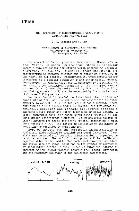
UB15-9
THE REFLECTION OF ELECTROMAGNETIC WAVES FROM A BANDLIMITED FRACTAL SLAB
D. L. Jaggard and Y. Kim
Moore School of Electrical Engineering University of Pennsylvania
Philadelphia, PA 10104
The concept of fractal geometry, introduced by Mandelbrot in the 1970's, is useful in the description of irregular deterministic and random structures which possess an infinite hierarchy of scales. Visually, th~se structures are characterized by symmetry dilation and so appear self-similar, in the mean, on all scales. Mathematically, these structures are identified by a fractal dimension D and other useful fractal descriptors. In general this fractal dimension is fractional and not equal to the topological dimension d. For example, smooth curves (d = 1) are characterized by D ~ 1 while wildly oscillating curves (d = 1) are characterized by D ~ 2 to indicate their area-filling nature.
We have found it useful to introduce the notion of bandlimited fractals in which the characteristic dilation symmetry is evident over a limited range of scale lengths. These structures are a cl9ser model to phycial reality since all naturally occuring and manmade structures possess a characteristic inner and outer dimension or scale length. A useful mathematic model for these bandlimited fractals is the bandlimited Weierstrass function. Below are shown several of these functions for three different fractal dimensions D with tone number N = 20. The latter is indicative of the number of scale lengths exhibited by each function.
Here we investigate the reflection characteristics of dielectric slabs modeled by bandlimited fractal functions. These slabs may be models of periodic, almost-periodic, imperfect or random structures. The tool of investigation will be the Riccati equation which can be used to find both exact numerical solutions and approximate analytical solutions to the problem· of relfection by bandlimited fractal slabs. These calculations indicate an interesting and general relation between the fractal dimension and the frequency variation of the reflection coefficient.
o::1.0'i N::::20
246
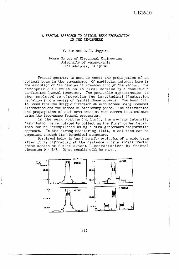
A FRACTAL APPROACH TO OPTICAL BEAM PROPAGATION IN THE ATMOSPHERE
Y. Kim and D. L. Jaggard
Moore School of Electrical Engineering University of Pennsylvania
Philadelphia, PA 19104
UB15-10
Fractal geometry is used to model the propagation of an optical beam in the atmosphere. Of particular interest here is the evolution of the beam as it advances through the medium. The atmospheric fluctuation is first modeled by a continuous bandlimited fractal function. The parabolic approximation is then employed to discretize the longitudinal fluctuation variation into a series of fractal phase screens. The beam path is found from the Bragg diffraction at each screen using Fresenel diffraction and the method of stationary phase. The diffraction and propagation of each beam order at each screen is calculated using the free-space Fresnel propagator.
In the weak scattering limit, the average intensity distribution is calculated by collecting the first-order terms. This can be accomplished using a straightforward diagrammatic approach. In the strong scattering limit, a solution can be organized through its hierachical structure.
Displayed below is the intensity evolution of a wide beam after it is diffracted at the distance z by a single fractal pha3e screen of finite extent L characterized by fractal dimension D = 5/3. Other results will be shown.
I/ 1 1
I..... a.a a.a
a.a a.a
1 1
a.a a.a
a.a a.a
247
! I

248

THURSDAY AM URS! SESSION UB16
SCATTERING & DIFFRACTION VI: NUMERICAL TECHNIQUES Chairman: R. Mittra, Univ of Illinois
Room: CEC, Auditorium Time: 8:30-12:00
8:40 A FINITE DIFFERENCE FREQUENCY DOMAIN APPROACH TO 250 ELECTROMAGNETIC SCATTERING PROBLEMS
9:00
R. T. Ling, Northrop
A NEW LOOK AT THE ASYMPTOTIC BOUNDARY FOR DIFFERENTIAL EQUATION APPROACHES OPEN REGION SCATTERINGPROBLEMS
R. Mittra, 0. Ramahi, University of Illinois; Mccartin, United Technologies Research Center
CONDITIONS TO SOLVIN~
G. Meltz, B.
251
9:20 ELECTROMAGNETIC WAVE SCATTERING BY A Two- 252 DIMENSIONAL CONDUCTING WEDGE USING ON-SURFACE RADIATION BOUNDARY CONDITION APPROACH S. Arendt, K. R. Umashankar, University of Illinois at Chicago; A. Taflove, G. A. Kriegsmann, Northwestern University
9:40 NUMERICAL SOLUTION OF THE COMBINED FIELD SURFACE 253 INTEGRAL EQATIONS FOR THE ANALYSIS OF ELECTROMAGNETIC SCATTERING BY ARBITRARY SHAPED TwoDIMENSIONAL ANISOTROPIC STRUCTURES
B. Beker, K. R. Umashankar, University of Illinois at Chicago; A. Taflove, Northwestern University
10: 00 ANALYSIS OF FINITE FREQUENCY SELECTIVE SURFACES P. W. Grounds, Naval Research Laboratory; K. J. Webb, Univeristy of Maryland
10:20 NUMERICAL SIMULATION OF Two-DIMENSIONAL STURCTURES OF ARBITRARY COMPOSITION J. L. Volakis, M.A. Ricoy, V. V. Liepa, T. A. Senior, The University of Michigan
10:40 IMPROVED COMPUTATIONAL METHOD ABSORPTION, AND INTERNAL FIELDS TICLES WITH DIAMETERS LESS THAN LAMBDA
FOR SCATTERING, OF DISC-LIKE PAR
OR EQUAL TO 4
T. M. Willis, H. Weil, The University of Michigan
254
255
256
11: 00 APPLICATION OF HYBRID-ITERATIVE METHOD TO A PER- 257 FECTLY CONDUCTING 0GIVAL CYLINDER
K. C. Hill, The Ohio State University; P. Murthy, G. A. Thiele, University of Dayton
11: 20 AN APPLICATION OF KSIENSKI 'S RESOLUTION ALGORITHM 258 TO NUMERICAL INTEGRATION
R. J. Pogorzelski, R. S. Lyons, TRW Space & Technology Group
11: 40 ON THE EXCITATION OF A CONDUCTING BODY OF REVOLU- 259 TION BY AN ASYMMETRICAL APERTURE
D. B. Davidson, Coucil Sci. Ind. Res.; D. A. McNamara, University of Pretoria
249

UB16-1
A FINITE-DIFFERENCE FREQUENCY-DOMAIN APPROACH TO ELECTROMAGNETIC SCATTERING PROBLEMS
R. T. Ling Northrop Aircraft Division
Hawthorne, California 90250
A finite-difference, frequency domain (FD-FD) approach to electromagnetic scattering pro bl ems has recently been proposed. (R. T. Ling, AIAA papers 86-1880 and 87-0487.) The FD-FD approach is a differential equation method based on the concept of the generalized scattering amplitude. The generalized scattering amplitudes in an electromagnetic scattering process are associated with components of scattered electric and magnetic field vectors. In an arbitrary orthogonal curvilinear coordinate system, which may be numerically generated, the vector problem of electromagnetic scattering can be reduced to two uncoupled scalar scattering problems involving scalar Debye potentials which satisfy the scalar Helmholtz equation and a simple Dirichlet or Neumann type surface boundary condition. The quantity in a debye potential that corresponds to the generalized scattering amplitude is defined as the Debye amplitude function. The Debye amplitude functions and the generalized scattering amplitudes are related through the generating equations, from which electric and magnetic field components are deduced from the Debye potentials. In the FD-FD approach, one solves the transformed Helmholtz equation with appropriate boundary conditions for the Debye amplitude functions.
By introducing the generalized scattering amplitude, the radially osci 11 atory part in the scattered field is separated from the non-oscillatory part. In the asymptotic region, the scattered field is composed of a radially oscillatory outgoing spherical wave modulating a scattering amplitude which is a function of scattering angle only. This asymptotic form for the scattered field components of Debye potentials is extended inwards throughout the scattering region by defining the De bye amplitude functions. The Debye amplitude functions are radially non-oscillatory and asymptotically approach their limiting values in the far field. The scattered electric and magnetic fields, which are derived from the Debye amplitude functions, remain oscillatory due to the modulating outgoing spherical wave.
In the FD-FD approach, the scattering of electromagnetic waves by an obstacle is formulated as a boundary value pro bl em analogous to the fluid dynamic problem of flows past the obstacle. Various numerical methods in Computational Fluid Dynamics (CFO) can be adapted to the computation of scattering characteristics. Numerical results based on the FD-FD approach will be presented for scattering of plane electromagnetic waves by two-dimensional airfoils and spheres.
250

UB16-2
A NEW LOOK AT TI1E ASYMPTOTIC BOUNDARY CONDmONS FOR DIFFERENTIAL EQUATION APPROACHF.S TO SOLVING OPEN REGION SCATI'ERING PROBLEMS
R. Mlltra an4 0. JlamamS G. Nau an4 B. NtCarnn.•
*Unii>rsity of I1linDi.s Url,ana, I1linDi.s 61801
-rlniud TechndDgies RlsaD-r:h Cc&to- East Hartford, Conna:tialt . 06108
Asymptotic boundary conditions (ABC), introduced by a number of authors including Bayn. and Turkel CB&T), Engquist and Majda (E&M), and Hariharan, enable one to conflne the region in which one needs to set up the :finite-element or :finite-difference mesh when 90lving an open region 11C&ttering problem using the partial differential equation techniques. For a twodimensional IIC&lar wave equation V 2 u + k2 (x,y) u = O, satiaft.ed by the wave function u. the most widely uaed version of the asymptotic boundary condition takes the form u,. = a(p)u + b(p~ which contains a aecond order angular derivative in u. Although, in principle, higher order, and presumably more accurate, boundary conditions can be derived containing higher order «/)-derivatives of u, it is not very desirable to uae them as the presence of the higher derivatives in ff, destroy the sparse nature of the FEM or FD matrices. If the asymptotic condition imposed on u on the bounding surface of the region is not sufficiently accurate, one possibility is to simply move this boundary farther out until the desired accuracy is achieved. This can be quite costly, however, becauae the number of node points increases rapidly with the radius of the outer boundary.
The purpose of this paper is fourfold: (1) To derive an alternate representation of the asymptotic boundary condition using an approach that is different from the ones employed either by B&T or E&M; (2) To interpret this boundary condition in terms of the propagating and evanescent spectral components of the 11C&ttered field in a manner that sheds 90me new insights into the 90urce of inaccuracies of the ABC; (3) To present suggestions for improving the accuracy of the 90lution derived from using the best available aecond order ABC; and, (4) To present numerical results based on the improved procedure.
251

UBI6-3
ELECTRctlAGNETIC WAVE SCATTERING BY A TWO-DIMENSIONAL CDNDUCTING WEDGE USING ON-SURFACE RADIATION 801.NDARY CONDITION APPROACH
Stephen Arendt Korada Umashankar
Department of Electrical Engineering and Computer Science University of Illinois at Chicago
Chicago, Illinois 60680
All en Tafl ave Department of Electrical Engineering and Computer Science
Northwestern University Evanston, Illinois 60201
Gregory Kriegsmann Department of Engineering Science and Applied Mathematics
Northwestern University, Evanston, 111 inois 60201
The on-surface radiation boundary condition approach introduces substantial simplification. for the analysis of electromagnetic scattering by homogeneous, isotropic two-dimensional conducting or dielectric objects. In this approach, the higher order boundary radiation condition is applied directly on the surface of the scatterer. This basically leads to a simple line integral for the scattered field in the frequency-domain. Specifically, for the case of two-dimensional convex conducting objects, the induced surface electric current distribution is known explicitly for TM-excitation, and is obtained as a solution to an ordinatry differential equation for TE-Excitation.
This paper reports further extension ~nd application of the on-surface radiation boundary condition (OSRC) approach to the analysis of two-dimensional TM- and TE- scatterers. It is shown, the OSRC is also applicable for wedge shaped conducting objects. In al imiting case, the OSRC operator does exhibit and predict singular nature of the field distribition near geometrical discontinuities.
The OSRC approach in general predicts stable numerical solutions; thus offers substantial advantage over other integral or integro-differential operator solutions. It is shown through a numerical example for a circular conducting cylinder, that there exists no internal resonance nor numerical instability problems inherent in the OSRC approach.
252

UB16-4
NUMERICAL SOLUTI~ OF THE COMBINED FIELD SURFACE INTEGRAL EQUATI~S FOR THE IWALYSIS OF ELECTR~GNETIC SCATTERING BY
ARBITRARY SHAPED TWO-DIMENSIONAL ANISOTROPIC STRUCTURES
Benjamin Bel<erKorada Umashanl<ar
Depar-tment of Electrical Engineering and Computer· Science University of Illinois at Chicago
Chicago, Illinois 60680
Allen Taflove Department of Electr·ical Engineering and Computer· Science
Northwestern University Evanston, Illinois 60201
An alternative approach is discussed for the analysis of electr·omagnetic scattering by arr arbitr-ary shaped two-dimensional homogeneous, anisotropic object located in an isotropic free space medium. The approach is based upon r-igorous integr-al equation solution. A set of combined field surface integral equations is obtained for the case of two-dimensional objects by tr-eating the electric and the magnetic sur-face fields as unknowns. Both transverse electric (TM) and transverse magnetic (TM) excitation cases are treated with no field var-iations along the axial direction of the arbitr-ary cross sectional geometry, The approach is suited for the media cases characterized by either- its per-mittivity or permeability tensor (diagonalizable).
A numerical method for solution of the coupled combined field surface integral equa ti ans is al so briefly discussed. The procedure leading to the final numerical solution is systematic and is based upon the method of moments. The combined field integral equations for TE and TM anisotropic dielectric scatterers or anisotropic permeable scatterers are solved by testing the integral equations with respect to I inear functions, and expanding the surface unknown fields in terms of simple pulse functions. Due to the nature of the combined field formulation based upon only the vector potentials, relatively fast converging numerical solution has been realized for the low and resonant size of anisotropic objects.
Numerical solutions for near surface electric and magnetic fields, far scattered fields of the canonical TE and TM anisotripic structures are presented. The results for the case of two-dimensional circular and square anisotropic structures are compared with respect to the solution obtained based upon the Finite-Difference Time-Doamin method.
253

UB16-5
ANALYSIS OF FINITE FREQUENCY SELECTIVE SURFACES
P. w. Grounds Naval Research Laboratory Washington, D.C.
K. J. Webb univ. of Maryland
In this paper, the reflection and transmission characteristics of finite frequency selective surfaces are analyzed. The computed results are compared both to experimental results and to the results obtained from the analysis of infinite frequency selective surfaces (C. H. Tsao, R. Mittra, IEEE A&P, May 1984).
Specifically, a freestanding square array of microstrip patches, where the dimensions of each patch are on the order of one wavelength, is investigated. The number of patches analyzed is varied.
The analysis uses the Method of Moments technique to solve a Greens function formulation of the problem in the spectral domain. The resulting set of equations is the same as that obtained in the infinite case except that the summation over spectral terms is replaced by an integral over the spectral domain. A Cray XMP-12 computer is used to solve the resulting set of simultaneous equations.
Various techniques are used to increase the speed of the calculation, such as formulating the integral in the system of coordinates most suited to the problem, using a variable size integration step, and using asymptotic approximations to functions in the integrand in the large argument limit.
254

NUMERICAL SIMULATION OF TWO-DIMENSIONAL STRUCTURES OF ARBITRARY COMPOSITION
J.L. Volakis, M.A. Hicoy, V. V. Liepa and T.B.A. Senior Radiation Laboratory
Dept. of Electrical Engineering and Computer Science The University of Michigan Ann Arbor, Ml. 48109-2122
UB16-6
The combined set of resistive and conductive sheets have been traditionally used in the simulation of material layers of arbitrary composition. It has been verified, though, that such a simulation is only approximate since it neglects certain current components whose contribition can be important in some cases. However, recently (T.B.A. Senior & J.L. Volakis, 1987) a modified set of electric and magnetic current sheets were derived and proven to represent an accurate simulation of the material layer. Thus, they can be thought as an improved set of sheets replacing the traditional resistive and conductive sheets.
The above set of sheets have proven useful in the numerical simulation of two-dimesional structures of arbitrary composition. In this case the structure is first subdivided in successive and sufficiently thin layers of material. Each layer is then replaced by the aforementioned pair of sheets. A numerical solution for the sheet currents can be subsequently found by introducing the boundary conditions characterizing the sheets. Such a formulation allows the concurrent modeling of the dielectric, magnetic or metallic properties of a structur and will be further shown to require only a maximum of two unknowns (per cell) for any material composition. In this paper several scattering patterns will be presented as computed by the code based on the above formulation. Comparisons will be also given with results generated by codes based on more traditional formulations such as the volume integral equation.
255

UB16-7
IMPROVED COMPUTATIONAL METHOD FOR SCATTERING, ABSORPTION AND INTERNAL FIELDS OF
DISC-LIKE PARTICLES WITH DIAMETERS~ 4 \.
Thomas M. Willis and Herschel Weil Dept. of Electrical Engineering and Computer Science
The University of Michigan Ann Arbor, MI 48109
The hybrid finite element-moment method of Weil and Chu (Appl. Opt. 19, 2066-2071, 1980) for computing induced internal current densities, scattering and absorption for thin homogeneous lossy dielectric discs has been extensively modified. The resulting computer code is much more accurate and efficient than the original and can also be used for highly conducting materials. It is applicable for any orientation of the disc relative to the transmitter direction, any angle between transmitter and receiver directions and any polarization. It gives accurate results for discs of thickness 6 and radius a which satisfy a/6 ::;1000 and 6/\ $ 1/12 where\ is the free space wavelength. The maximum a/\ for accurate results depends on the. maximum size 1 inear algebraic matrix equation one specifies to be used in the computation. For example for 30 x 30 matrices, a/\$ 2. These approximate bounds are partly based on extensive comparisons if our results for lossy dielectries with the following; published microwave experimental data (Allen and McCormick, IEEE.Trans. AP-28, 166-169, 1980) and corresponding computations by a very different procedure (Shepherd and Holt, J. Phys. A. 16,
·651-662, 1983). Comparisons were also made with approximate theories in their regions of validity; physical optics in the sense used by LeVine et. al. (IEEE Trans. AP-33, 1410-1413, 1985) and Rayleigh Theory using data computed by a modification of the procedure in Senior and Willis (IEEE Trans. AP-30, 127, 1982).
For highly conducting materials we compared our results with published microwave data for flat thin silver discs and accompanying theoretical curves computed for infinitely thin perfectly conducting oblate spheroids (De Vore, et. al., J. Appl. Phys. 42, 3075-3083, 1971).
256

UB16-8
APPLICATION OF t-!YBKID-ITEKATIVE METHUO TU A PEKFECTLY CONDUCTING UGIVAL CYLINDJ<.:K
K. C. HILL THE OHIO STATE UNIVERSITY
ELECTRICAL ENGINEEKING DEPARTMENT ELECTKOSCIENCE LABORATORY
COLUMBUS, OHIO 43212
P. K. MURTHY AND G. A. THIELE ELECTROMAGNETICS GROUP
UNIVERSITY OF DAYTON DAYTON, OHIO 45469
Scattering from an ogival cylinder illuminated by a TE-plane wave is considered here. This geometry involves both the edge diffraction and smooth surface diffraction and is intended to test the recently evolved technique called the hybrid iterative method (HIM). This technique solves the MJ:<'IJ<.: tor surtace currents on a closed scatterer. An initial estimate for the shadow side current is necessary to start the iterative scheme. This initiaL estimate is obtained by heuristically combining edge- and smooth-surface diffraction.
Using HIM, surface currents and scattering patterns are computed for several ditferent angles of incidence and also for different ogival angles. The length .. _ of the ogive is kept at three wavelengths. These results are compared with those obtained via the method of moments (MM). In general, good agreement is obtained between MM and HIM. However, these results are valid only for ogival angles greater than about 60°. For narrower angles, the heuriatic formula for initial current on the shadow side ceases to be a sufficiently good estimate.
257

UB16-9
AN APPLICATION OF KSIENSKI'S RESOLUTION ALGORITHM TO NUMERICAL INTEGRATION
R.J. Pogorzelski and R.S. Lyons TRW Space and Technology Group
One Space Park Redondo Beach, CA 90278
An algorithm recently described by Pogorzelski and Mallery (IEEE Trans. AP-33, 563, 1985) is particularly efficient for numerical integration of rapidly oscillating integrands. This algorithm expresses the integral as a sum of constituent integrals which can be computed recursively. If such an algori thro Ci'!n be generalized to two dimensions, it would find broad application in computational electroroagnetics as a means of efficiently computing fields radiated by surface currents. Efforts to carry out such a generalization have followed a variety of paths but the roost fruitful to date appears to be repeated application of the one dimensional algorithm. The difficulty encountered is that the result of the set of integrals on the first variable is not in the proper (smooth magnitude and smooth phase) form for application of the one dimensional recursive algorithm in computing the integral over the second variable.
Until now the above difficulty has been circumvented by modifying the recursive procedure to yield results in the desired form. This, however, destroys the numerical stability of the recurrence and thus severely limits the performance of the algorithm. Fortunately, Ksienski (IEEE Proc., 73, 166, Jan .. 1985) has provided a method of resolving the rapidly oscillating result of the first set of integrations into components having smooth roagni tude and phase as required for the second application of the one dimensional algorithm. The resulting two dimensional algorithm then consists of repeated one dimensional integration on one variable followed by resolution of the result into smooth magnitude and phase components and one dimensional integration on the other variable. In cases where it is not efficient to explicitly account for rapidly varying phase, this algorithm reduces to a variant of two dimensional GaussChebyshev quadrature with a provision for accuracy monitoring.
258

ON THE EXCITATION OF A CONDUCTING BODY OF REVOLUTION BY AN ASYMMETRICAL APERTURE
UB16-10
D.B. Davidson, Council Sci. Ind. Res., Pretoria, South Africa. (Formerly graduate student, Dept. Electronics and Computer
Engineering, University of Pretoria). D.A. McNamara, Dept. Electronics & Computer. Eng., Univ. of
Pretoria, 0002 PRETORIA, South Africa
The body of revolution ( BOR) formulation is a very effective way of extending the applicability of method of moments techniques. The resulting increase in the size of the structures (surfaces) which can be analysed has allowed the approach to be successfully applied in the design of a number of antenna types (D. McNamara et. al., IEEE AP-S Symp. Digest, 1984; D.E. Baker and L. Botha, Allerton Ant. Appl. Symp., 1986). The original formulation ( Harrington and Mautz, Appl. Sci., Res., June 1969) handles only symmetrical excitation. Subsequently this was extended to permit excitation by asymmetrical slots (Mitschang and Mullen, IEEE Trans. AP, Jan. 1976). However, this latter reference is brief and contains insufficient detail to allow straightforward development of a computer code.
In this paper, the missing steps which do not appear to be available elsewhere in the literature are provided, some novel viewpoints introduced, certain typographical errors in the above reference corrected, and the effects of using different aperture distributions shown. A computer code for the asymmetrical excitation problem has been developed by the present authors. The application of the code to several antenna examples is presented, with comparison to measurements.
Finally, there is the important problEci of convergence of the BOR solution relating to the required number of circumferential modes and basis functions along the generatrix. This problem has not been fully discussed in the literature, and the results of a detailed study (D. Davidson, Master's Thesis, Univ. of Pretoria, 1987) by the authors will therefore be given.
259

260

THURSDAY AM
URS! SESSION UB17 NUMERICAL METHODS IV
Chairman: D. R. Wilton, Univ of Houston Room: Squires, Old Dominion Blrm Time: 8:30-12:00
8:40 A NUMERICAL FORMULATION FOR THE MUTUAL ADMITTANCE 262 BETWEEN FINITE SLOTS IN CYLINDERS OF ARBITRARY CROSS SECTION SHAPE
A. F. Peterson, R. Mittra, University of Illinois
9:00 MODELING OF THE SCATTERING FROM ANISO- 263 TROPIC CONDUCTORS WITH ELECTRIC-FIELD-!NTEGRAL-EQUATION METHOD-OF-MOMENTS CODES
K. J. Harker, SRI International
9:20 METHOD OF MOMENTS ANALYSIS OF A CLAVIN ELEMENT 264 S. R. Rengarajan, W. Li, California State University
9: 40 A MOMENT METHOD ANALYSIS OF THE THICK WALLED 265 WAVEGUIDE E-PLANE TEE JUNCTION
W. T. Carey, Raytheon Company
10:00 MININEC II: AN IMPROVED VERSION OF MININEC FOR 266 PERSONAL COMPUTERS
W. A. Davis, D. G. Sweeney, W. L. Stutzman, Virginia Polytechnic Institute & State University
10:20 STABILITY CONSIDERATIONS IN THE FIELD FEEDBACK 267 FORMULATION
M. A. Morgan, Naval Postgraduate School
10:40 A HYBRID FINITE/INFINITE METHOD FOR THE ANALYSIS 268 OF WAVEGUIDE PHASED ARRAYS
D. C. Power, Raytheon Company
11 :00 NUMERICAL SOLUTIONS OF INDUCED EM FIELDS IN 269 FINITE BODIES WITH ARBITRARY PARAMETERS
H. Wang, K. M. Chen, Michigan State University
11: 20 INVESTIGATION OF THE NEAR-NEIGHBOR APPROXIMATION 270 IN INTEGRAL-EQUATION MODELING
E. K. Miller, K. R. Demarest, L. K. Wu, K. Kalbasi, The University of Kansas; G. J. Burke, Lawrence Livermore National Laboratory
11: 40 APPLICATION OF THE FINITE ELEMENT METHOD TO 271 DESIGN WAVEGUIDE DIPLEXERS
A. Gebauer, F. Hernandez-Gil, Telefonica
261

UB17-1
A NUMERICAL FORMULATION FOR THE MUTUAL ADMITTANCE BETWEEN FINITE SLOTS IN CYLINDERS OF ARBITRARY CROSS SECTION SHAPE
A. F. Peterson and R. Mittra El.ectromagnetic Communi.cat.ion Laboratory
Universil.y of Illinois Urbana, Illinois 61801
Both the proper design of slot arrays and the positioning of multiple antenna arrays on a common surface require an accurate estimate of the mutual coupling between individual slot elements. To date, the analysis of mutual admittance has been undertaken for slot elements in simple shapes such as circular cylinders, cones, and spherical surfaces. Limited attempts have also been made to treat more general surface shapes using asymptotic methods. In an effort to extend this type of analysis to arbitrary geometries, the present investigation considers a numerical solution for the mutual coupling between individual, finite-sized slots in an infinite, conducting cylinder of arbitrary cross section. Both axial and circumferential slots are considered.
The mutual coupling problem is posed in such a manner as to make it amenable to convenient numerical solution. The equivalence theorem is used to replace the. source slot by magnetic currents radiating in the presence of the closed cylinder. Next, the original three-dimensional problem is replaced by a series of equivalent two-dimensional problems via the use of the Fourier transform in the axial direction. The two-dimensional problems are initially solved using the magnetic field integral equation (MFIE), producing the equivalent electric current density on the cylinder. The superposition of these two-dimensional solutions in accordance with the inverse Fourier transformation produces the three-dimensional current density, which is used to compute the mutual admittance. The formulation requires that the two-dimensional problem be solved at a large number of spatial frequencies.
The results obtained via the use of this approach are found to be in good agreement with the available data for slots in circular cylinders, except in certain cases when the MFIE formulation fails because the cylinder geometry under consideration corresponds to a resonant cavity. A variety of alternatives exist for the eradication of the "interior resonance" problem. Unfortunately, all the existing methods require a significant increase in the computational overhead compared with the original MFIE formulation. Methods based on the addition of interior strips to the model or the overspecification of the equation at interior points can eliminate the resonances at a single frequency, but not over the broad bandwidth desired (unless many interior points are used). Methods based on the combined-field, combined-source, and augmented field equations have two drawbacks. In addition to not being immediately compatible with the simple pulse basis function - point matching discretization used with the MFIE, these methods require additional unknowns and a corresponding increase in matrix fill and solve times. An evaluation of the computational overhead associated with each of these methods is developed.
262

UB17-2
MODELING OF THE SCATTERING FROM ANISOTROPIC CONDUCTORS WITH ELECTRIC-FIELD-INTEGRAL-EQUATION METHOD-OF-MOMENTS CODES
Dr. Kenneth J. Harker SRI International
333 Ravenswood Avenue Menlo Park, CA 94025
A study has been made of the electromagnetic scattering from bodies composed of both isotropic and anisotropic conductors using electricfield-integral-equation method-of-moments codes and the results are reported here. By making the conductivity very small in one direc.tion along a surface and very large in the orthogonal direction on that surface, it is possible to model materials that support a current distribution which is essentially unidirectional at each spatial point. This capability, for example, allows us to use a surface code to model closely spaced wire arrays that are part of a larger metallic body.
Using the basic method-of-moments (MOM) equations, it is shown how the MOM impedance matrix must be modified to encompass a general anisotropic conductor. A comparison will be made between the results obtained for an anisotropic conductor and an equivalent wire mesh using a body-ofrevolution electric-field-integral-equation code.
263

UB17-3
METHOD OF MOMENTS ANALYSIS OF A CLAVIN ELEMENT
Sembiam R. Rengarajan Wing Li
Department of Electrical and Computer Engineering California State University, Northridge
Northridge, CA 91330
The Clavin element consisting of a slot and two monopoles on a broad wal I of a rectangular waveguide has been studied by Papirez et al. (Proc. IEE, 124, pp. 25-30, 1977) among others. Recently, El I iott analyzed the mutual coup I ing between Clavin elements (IEEE Trans. AP-28, 6, pp. 864-870, 1980). Ti I I date there is no method of moments analysis of this structure. In this paper, dual integro differential equations for slot fields and monopole currents are developed in terms of Stevenson's Gree.ns functions and "reduced kernel". A sinusoidal global Galerkin approach is used for the slot while a pulse function point matched Hal len technique is employed for the monopoles. The slot field distribution, currents in monopoles, slot admittance and radiation patterns of this element are discussed for a range of physical parameters. The computer program developed in this work helps optimization of any of the characteristics of this element.
264

A MOMENT METHOD ANALYSIS OF THE THICK WALLED WAVEGUIDE E-PL.ANE TEE JUNCTION
w. Timothy Carey
Raytheon Company Missile Systems Division
Hartwell Road Bedford, Ma. 01730
UB17-4
An analysis has been completed of the waveguide E-Plane Tee junction that specifically incorporates the effects of wall thickness in the coupling region between the two waveguides. Previous· studies by various authors typically begin with the infinitely thin wall case and then adapt the results to thick wall cases through the application of correction factors involving the propagation or attenuation constants appropriate to the dominant mode of the coupling slot. The present analysis seeks to bypass this approximation by directly aproaching the problem as two waveguides which couple to each other through a cavity. The problem is analyzed through a generalized network formulation of the type employed by Harrington and Mautz ( IEEE Trans. Antennas Propagat., vol AP-24, no. 6, Nov. 1976 ) for aperture problems. A set of coupled operator equations is developed with the equivalent magnetic currents on either side of the thick wall as the unknown quantities. These operator equations are then solved through the application of Galerkin's technique where the basis and testing functions correspond to the waveguide modes of the coupling aperture cross-section.
The solutions of several problems of general interest are presented for coupling between waveguides of identical cross-section when the coupling aperture is either rectangular or circular. Particula·r emphasis is placed upon the effect of wall thickness upon both the phase and amplitude of the transmitted, reflected and coupled signals. Comparisons are made to thin wall solutions employed by other authors.
Comparisons with experimental results, indicating the accuracy of the technique, are also presented. A practical configuration is employed which consists of an elongated slot of the type discussed by Lagasse and Van Blade! ( IEEE trans. Mi cowave Theory Tech., vol. MTT-20, no. 5, May 1972) for wall thickness of dimensions typically associated with commercially available waveguides.
265

UB17-5
MININEC II: AN IMPROVED VERSION OF MININEC FOR PERSONAL COMPUTERS
w. A. Davis, D. G. Sweeney, w. L. Stutzman Department of Electrical Engineering
Virginia Polytechnic Institute and state University Blacksburg, VA 24061, USA
The Mini-Numerical Electromagnetics Code (MININEC) is a frequency domain Method of Moments (MOM) computer code for the analysis of wire antennas. MININEC is a personal computer version of the more extensive Numerical Electromagnetics Code (NEC). While MININEC has proven to be a useful tool there are certain limitations placed on it by the original algorithm and the personal computer environment. This paper describes some of the enhancements and improvements to MININEC to overcome these limitations.
MININEC gave inaccurate results for very small diameter or very closely spaced wires, thus it could not analyze such simple structures as a low frequency wire antenna, a closely spaced yagi or a folded dipole. The method by which MININEC determines the distance from a point on a wire segment to a point in space was modifed to correct this deficiency.
The original MININEC was written in BASIC for a personal computer with limited memory. MININEC II is written in Turbo Pascal, an inexpensive and widely available Pascal compiler. This new computer environment results in an increase in speed and access to significantly more memory both of which permit the analysis of larger and more complex structures. MININEC II also has simple plotting routines which can produce current distribution and pattern plots.
' MININEC II has been extensively tested using a number of problems that have either analytic or published solutions. This paper includes a presentation of several of these problems and a comparison of the solutions given by MININEC and MININEC II with known solutions. Prominent among these problems is the folded dipole.
266

STABILITY CONSIDERATIONS IN THE FIELD FEEDBACK FORMULATION
Michael A. Morgan Uepnrtment of Electrical & Computer Engineering
Naval Postgraduate School Monterey, CA 93943
3 The Field Feedback Formulation (F ) was developed by Morgan and Welch (IEEE Trans. Ant. Propag·at., AP-:34, Dec. 1986) as a systematic and economical means for solving scattering problems via the use of differential equation based numerical methods, such as finite elements. To provide this service, the discretized scattering problem is recast ass multiport recursive feedback system. The global transfer function of this system is equal to the T-matrix of the scatterer.
An important question lob§ considered here concerns the numerical conditioning of the,· scattering solution method. This conditioning can be shown to be directly dependent upon the stability of the resultant feedback system. The results of this study will employ both theoretical and computational arguments to od<lress the question of system stability as a function of both the physical attributes of the scatterer and the parameters of the discretizement process. Simple example computations will be presented to illustrate the conclusions.
267

UB17-7
A HYBRID FINITE/INFINITE METHOD FOR THE
ANALYSIS OF WAVEGUIDE PHASED ARRAYS
D. C. Power
Raytheon Company Missile Systems Division
Hartwell Road Bedford, Ma 01730
A hybrid method is developed which combines the standard infinite array analysis with the finite array mutual coupling method developed by Luzwick and Harrington (Electromagnetics 2:25-42,1982). The idea is fundamentally the same as the hybrid method of moments techniques which have been used by various authors in scattering problems. The problem is first formulated as a finite array and the operator equation is developed with the equivalent magnetic current on the array element apertures as the unknown quantity. The ansatz is made that the magnetic current on the elements a sufficient distance from the edges of the array is identical to the magnetic current which would exist on the elements of an infinite array. These magnetic currents are obtained from the solution of the infinite array problem, and once known, contribute to the field incident on the remaining (edge) elements. The operator equation is then solved by the method of moments with the effect of the central elements augmenting the excitation vector of the matrix equation. The order of the matrix is determined by the number of edge elements rather than the total number of array elements.
The method displays the same advantages for antenna analysis as the hybrid methods have shown for scattering problems. Large but finite arrays can be investigated without neglecting the effects of the edge elements and without the solution of exceedingly large matrices. Array illumination functions which are constant over the central elements and tapered on the edge elements are directly implementable into the formulation. A disadvantage of the method (over a pure finite array method) is that although the matrix representing the edge elements need be filled and inverted only once, the matrix equation which must be solved for the elements assumed to be in the infinite array environment must be filled and solved for each scan angle of interest.
268

UB17-8
NUMERICAL SOLUTIONS OF INDUCED EM FIELDS IN FINITE BODIES WITH ARBITRARY PARAMETERS
Huei Wang and Kun-Mu Chen Department of Electrical Engineering and Systems Science
Michigan State University, East Lansing, MI 48824
Numerical Solutions of induced EM fields in finite bodies with arbitrary parameters are investigated. Chen (Research Topics in EM Wave Theory, Ed. J. A. Kong, John Wiley and Sons, 1981) has derived a set of coupled integral equations to express the induced electric field and the induced magnetic field inside the body, with arbitrary permittivity, permeability and conductivity, in terms of the incident electric field and the incident magnetic field. This set of coupled integral equations can be decoupled into a separated electric field equation (EFIE) and a separated magnetic integral equation (MFIE). Induced EM fields inside lossy, dielectric and magnetic bodies are being determined numerically using both the set of coupled integral equations and the two decoupled EFIE and MFIE. Efficient numerical methods are being developed to solve these integral equations.
One numerical method is the conventional pulse-basis expansion with · point matching, while the other method utilizes Lagrangian linear functions as the basis function with Galerkin's and/or subdomain testing procedures. The latter method has the advantages that it guarantees the continuity of the induced EM fields, in both normal and tangential components, between adjacent homogeneous cells and it is insensitive to the locations of matching points. The disadvantage of this method is a long computation time needed for the matrix elements. In order to save computer time, the testing procedures for the latter method have been modified.
269

UB17-9
INVESTIGATION OF THE NEAR-NEIGHBOR APPROXIMATION IN INTEGRAL-EQUATION MODELING
. * * * ·* E. K. Hiller , K. R. Demarest , L. K. Wu , K. Kalbas1 , 6. J. Burke**
*oepartment or Electrical and computer Engineering University or Kansas, Lawrence, KS 66045 **Lawrence Livermore National Labatory
Livermore, CA 94550
One of the approaches that may make more feasible the integral-equation, moment-method modeling of objects large with repsect to the excitation wavelength is the near-neighbor approximatJon CNNA). The basic premise of the NNA is that direct interaction between locations on an object falling below some specified threshold might be neglected in computing the impedance matrix to achieve an approximate, but acceptably accurate solution while using less computer time and storage. The threshold selected defines an interaction window which may be applied to spatial or modal interactions. In this paper we explore some aspects of the NNA via computer experiments conducted on a set of generic object geometries.
Our discussion begins by reviewing past work concerning the NNA. We then outline a series of computer experiments for such simple objects as straight wires, circular loops, and right circular cylinders. Various measures of solution accuracy based on the admittance matrix, source distributions, and far fields are investigated as a function of object and window size in wavelengths and the excitation. In order to suitably test the performance of the NNA, we exploit the symmetry of the right circular cylinder to solve a problem having many thousands of unknowns. An information- content model for the impedance matrix is suggested as one way of developing an a priori prediction of the expected error in the solution. We also examine the error in terms of object geometry and window size and suggest a physical explanation for the results observed.
270
APPLICATION OF THE FINITE ELEMENT METHOD TO DESIGN WAVEGUIDE DIPLEXERS
A. Gebauer and F. Hernandez-Gil R&D Dpt. Telefonica
C/ Lerida 43, 28020 Madrid, Spain
UB17-10
Waveguide diplexers formed by E-plane filters and T-juntions have proved to be useful in comunications systems. However most of reported works use approximated methods to analyze the T-juntion and do not consider the higher mode interaction between the filters and the junction. We. have applied the finite element method to analyze the whole diplexer. All discontinuities effects are taken into account and the T-junction can be optimized to improve the diplexer characteristics.
The generalized scattering matrix of N-ports waveguide structures is computed using the finite element method. The method uses third order polynomials to expand the field inside the waveguide. Boundary condictions at the end of each port are applied using the analytical expression of the waveguide modes. The field singularities in the structure corners are taken into account to improve the convergence of the method.
The results obtained with this method for E-plane filters were compared with those obtained· using modal expansion techniques and good agreement were observed. The power balance in the circuit is usually better than lOE-10. Good agreement were also observed with the results reported by Koshiba for waveguide T-juntions (Transactions IECE of Japan, Feb. 1983, pp.82-87 ),
To design the diplexer two E-plane filter with the desired response are first designed. The two filters and the T-juntion are linked to obtain a three port diplexer. The distance between the filters and the junction are adjusted to optimize the matching. This method has been applied to design a Ka-band diplexer to be used in communication systems. The measurements· show good agreement with the calculated results.
271

272

THURSDAY PM
URSI SESSION UB18 WAVES AND INTERACTIONS
Chairman: K. A. Michalski, Texas A&M Univ Room: CEC, Meeting Room B Time: 1:30-5:00
1: 40 WHAT IS A HERTZ IAN DIPOLE AT THE INTERFACE 274 BETWEEN Two DISSIMILAR HALF-SPACES?
C. M. Butler, X. Xu, Clemson University; K. A. Michalski, Texas A&M University
2:00 RADIATION CHARACTERISTICS OF AN ANTENNA LYING ON 275 THE SURFACE OF A DIELECTRIC LAYER
N. Engheta~ California Institute of Technology; C. Elachi, Jet Propulsion Laboratory
2:20 MAGNETIC FIELD DUE TO STATIONARY CURRENTS 276 INJECTED INTO A CONDUCTING HALF SPACE A. Sezginer, T. M. Habashy, Schlumberger-Doll Research
2:40 THE MIXED-POTENTIAL EFIE APPROACH TO THE ANALYSIS 277 OF THIN-WIRE ANTENNAS OF ARBITRARY SHAPE RESIDING IN CONTIGUOUS DIELECTRIC HALF-SPACES
D. Zheng, The University of Mississippi; K. A. Michalski, Texas A&M University
3 :00 ON THE SOMMERFELD-INTEGRAL REPRESENTATION OF THE 278 ELECTRIC DYADIC GREEN'S FUNCTION FOR LAYED MEDIA
M. S. Viola, D. P. Nyquist, B. C. Drachman, Michigan State University
3: 20 A REPRESENTATION FOR THE GREEN'S DYADIC OF LINEAR 279 ARRAY OF CURRENT SOURCE ORIENTED PARALLEL TO THE INTERFACES OF A MULTILAYTERED MATERIAL REGION
L. W. Pearson, McDonnell Douglas Research Laboratories
3: 40 AN INVESTIGATION OF THE BEHAVIOR OF THE CURRENT 280 AT THE BEND OF A TM-EXCITED BENT STRIP ON THE INTERFACE BETWEEN Two HALF SPACES
C. M. Butler, X. Xu, Clemson University
4: 00 REFLECTION AND PROPAGATION CHARACTERIS- , 281 TICS OF MULTIPLE LAYERS OF ANISOTROPIC ADMITTANCE SHEETS
L. W. Pearson, McDonnell Douglas Research Laboratories
4: 20 ELECTROMAGNETIC WAVE SCATTERING FROM A HALF-SPACE 282 HAVING RAPIDLY TIME-VARYING CONDUCTIVITY
F. Harfoush, A. Taflove, G. A. Kriegsmann, Northwestern University
4:40 A STUDY OF RADAR SCATTERING FROM NEAR-INTERFACE 283 TARGETS
E. K. Miller, The University of Kansas; G. J. Burke, J, K. Breakall, Lawrence Livermore National Laboratory
273

UB18-l
WHAT IS A HERTZIAN DIPOLE AT THE INTERFACE BETWEEN TWO DISSIMILAR HALF-SPACES?
Chalmers M. Butler and Xiao-Bang Xu Department of Electrical and Computer Engineering
Clemson University Clemson, SC 29634-0915
and
Krzysztof A. Michalski Department of Electrical Engineering
Texas A & M University College Station, TX 77843-3128
The authors have observed that the vector potential, hence the corresponding field components, evaluated at a point in space due to a horizontal electric dipole on or at the interface between two dissimilar half-spaces is a well defined quantity. On the other hand, the vector potential due to a vertical dipole on or at the interface is not adequately defined. The inadequacy is explained as follows. At a given field point the vector potential due to a dipole in the upper half-space is well defined as is that due to a dipole in the lower half-space. However, in the limit as the upper- and lower-half-space dipoles approach a common point on the interface, one observes that the resulting potentials at a point in space are the same in the case that the dipoles are .parallel to the interface but are different in the case that the dipoles are perpendicular to the interface. The.ratio of the potentials of these vertical dipoles differ by the ratio of the permi tti vi ties of the two half-spaces. Consequently, a traditional vertical dipole at or on the interface is not an adequately defined radiator one must augment the specification with additional information.
The same behavior is found for two-dimensional sources. The potential due to a line current on the interface is well defined as is that due to a line dipole parallel and on the interface. But a line dipole normal to and located on the interface is ill-defined. Again, one finds that the ratio of the potentials at a point in space due to normal line dipoles which approach the interface from locations in the upper- and lower-half-spaces differ by the ratio of the permittivities.
The validity of the above claims is established in the paper and corresponding properties are enumerated for magnetic sources and static sources.
274
----- --- -~----

RADIATION CHARACTERISTICS OF AN ANTENNA LYING ON THE SURFACE OF A DIELECTRIC LAYER
N, Engheta California Institute of Technology
Pasadena, California 91125 and
c. Elachi Jet Propulsion Laboratory
California Institute of Technology Pasadena, California 91109
UB18-2
One of the interesting problems of remote sensing is the problem of reflection and refraction of the electromagnetic wave illuminating a rough surface covered with a dielectric layer. This could be a vegetation layer. The top surface of the layer can also be rough. There are different theoretical models that can simplify the geometry of the problem and thus can lead to finding the reflection and refraction of the wave. One of the techniques that can be used in solving the problems of the scattering from rough surfaces is the equivalent current source technique that was used by Marcuse (Theory of Dielectric Optical Waveguides, 1974) and also by Elachi and Yeh (J, of Applied Phys. 45, (8) 3494-3499, 1974), In using this technique, the slightly rough surface is replaced by a smooth surface and equivalent sources that would be located on the surface. Therefore, the original problem reduces to the problem of finding the radiation of sources that lie on interfaces.
In the present work, the rough surfaces of the dielectric layer can be replaced by smooth surfaces and interfacial sources. The radiation pattern of an interfacial source is obtained when the source is lying along the top or the bottom surface of the dielectric layer. This layer is assumed to be on the top of a semi-infinite dielectric medium with a different permittivity. It is found that in both cases, the pattern along interfaces has a null; that the pattern in the upper medium has a single lobe; and that the pattern in the lower semi-infinite medium has many lobes the number of which varies with the dielectric thickness. It is shown that the power radiated into the lower medium is more than that of radiated into the upper_ medium. The interpretation of these results in terms of ray optics is given.
275

UB18-3
MAGNETIC FIELD DUE TO STATIONARY CURRENTS INJECTED INTO A CONDUCTING HALF SPACE
A. Sezginer and T.M. Habashy Schlumberger-Doll Research, Ridgefield, CT 06877
An image method for computing the static magnetic field due to an arbitrary current injected into a conducting half space is derived. The geometry of the problem is illustrated in Fig. 1. A filamentary, d.c. source of magnitude I whose terminals are situated at the points r 1 and r 2 , is embedded in a homogeneous and conducting half space z < 0 of permeability µ. The region z > 0 is free space, which has the permeability µo,
The static magnetic field is computed using the Biot-Savart operator L :
where J is the volume current density representing the filamentary current source or its derived images. The main advantage of this approach is that the conduction currents in the conducting half space do not enter into the computation.
The magnetic field in the region z > 0 {z < O} is shown to be LJ, where J is the filamentary current source depicted in Fig. 2 { 3}. The vertical sections of the impressed current sources in Fig. 2 and 3 are infinite in extent, and they are perpendicular to the z = 0 plane. The current in Fig. 2 is H·= 2Iµ/(µ, 0 + µ), throughout the impressed current filament. In Fig. 3, the vertical current filaments are of magnitude I2 , and the mirror image of the original source filament is of strength Ii·= I(µ,o - µ) / (µo + µ,). The orientation of the currents are as shown in the figures.
Fig. 1 Fig. 2 Fig. 3
276

THE MIXED-POTENTIAL EFIE.APPROACH TO THE ANALYSIS OF THIN-WIRE ANTENNAS OF ARBITRARY SHAPE RESIDING
IN CONTIGUOUS DIELECTRIC HALF-SPACES
Dalian Zheng and Krzysztof A. Michalski Department of Electrical Engineering
University of Mississippi University, MS 38677, USA
UB18-4
An integral equation is formulated and solved numerically for the current distribution on a thin wire antenna of arbitrary shape which penetrates a planar interface between two dielectric half-spaces. The formulation employs a new form of the so-called mixed-potential Electric Field Integral Equation (EFIE) (K.A. Michalski, AEU, 39, 317-322, 1985) which is amenable to the existing moment method procedures developed for bodies of arbitrary shape in homogeneous media (A.W. Glisson and D.R. Wilton, IEEE Trans., AP-28, 593-603, 1980; S.M. Rao et al., ibid., AP-30, 409-418, 1982). Hence, we are motivated by similar ideas as W.A. Johnson (Radio Sci., 18, 1273-1281, 1983), who solved the special case of a vertical, tubular antenna in contiguous half-spaces.
The effect of the interface between the two dielectric media is accounted for via, essentially, the classical Sommerfeld's theory (A. Sommerfeld, Ann. Phys., 28, 665-737, 1909), with some modifications. For example, for a horizontal, say, x-directed dipole, we have found it more efficient to use the x- and ycomponents of the magnetic vector potential rather than the xand z-components, as has been a common practice since the Sommerfeld's original paper (A. Sommerfeld, op. cit.).
The purpose of this research is twofold: first, to contribute to the understanding of the behavior of antenna structures which penetrate the interface between two media and, second, to corroborate our new integral equation formulation. Numerical results are presented for several cases of interest and are compared in special cases with results obtained by other researchers (W.A. Johnson, op. cit.; C.C. Lin and K.K. Mei, Elelctromagn., 2, 309-334, 1982; G.J. Burke and E.K. Miller, IEEE Trans., AP-32, 1040-1049, 1984) and with experimental results.
277

UB18-5
ON THE SOMMERFELD-INTEGRAL REPRESENTATION OF THE ELECTRIC DYADIC GREEN'S FUNCTION FOR LAYERED-MEDIA
Mark S. Viola and Dennis P. Nyquist Department of Electrical Engineering and Systems Science
Byron C. Drachman Department of Mathematics
Michigan State University East Lansing, Mi chi gan 48824
The electric dyadic Green's function for layered media is discussed. It is well known that for the free-space electric dyadic Green's function G0 , evaluation of the electric field at observation points withi.Q the source region requires specification of a depolarizing dyad 'L. The dyad t is dependent on the geomet_£Y of the "principal volume" which excludes the singularity of G0 • Special considerations are invoked for the layered background media which are appropriate for the electromagnetics of integrated electronics.
The relevant equation which uniquely defines the electric field maintained by arbitrarily located electric currents in a layered environment is established. Beginning with
--,.--,. 2 f 4 # -+-+ E(r)=(k + VV•) (GP+ Gr)·J(r' )dV' c V
(1)
and using th~ommerfeld-integral representation for the dy2_gs ("principal" 'GfJ has the pertinent singularity, "reflected" G' is well behaved) appearing in the integrand of (1), it is shown that the electric field may be expressed as
--,.--,. J +r -+-+ -+-+ +r-+-+ E(r)=-jw110 lim Ge(r;r')·J(r')dV' - L·J(r)/jwsc
o+O v-v6
(2)
where Ge and L are quantified.
In conclusion, it is shown that for the layered-media electric dyadic Green's function, the Sommerfeld-integral representation is appropriate and leads to an innate option for the principal volume. The correction term in (2) is precisely the depolarizing dyad corresponding to this preferred choice of the excluding region.
278
A REPRESENTATION FOR THE GREEN'S DYADIC OF A LINEAR ARRAY OF CURRENT SOURCE ORIENTED
PARALLEL TO THE INTERFACES OF A MULTILAYER MATERIAL REGION
L. W. Pearson, McDonnell Douglas Research Laboratories, P. 0. Box 516, Saint Louis, MO 63166
UB18-6
The Green's dyadic for the magnetic vector potential of a current element radiating over a region comprising multiple layers of materials with different properties is well known; it is typically expressed as a Sommerfeld-type integral that is formally a Hankel transform of order zero. With appropriate interpretation of terms in the vector-potential dyadic, one can relate the magneticvector-potential representation for the field to a Hertzian potential representation in which the fields are a superposition of fields transverse magnetic (TM) and transverse electric (TE) to the direction normal to the interface. Michalski has recently demonstrated that one can just as simply express the fields as a superposition of fields TM to two orthogonal directions parallel to the interface (K.A. Michalski, private communication).
The zeroth-order Hankel transform in the potential representation is equivalent to a two-dimensional Fourier transform. This double Fourier transform can be viewed as a canonical form for introducing periodic sources into the representation. The introduction of source periodicity in a given direction allows the Fourier transform associated with that direction to be converted by way of the Poisson sum formula into a rapidly convergent sum of Floquet modes. For doubly periodic structures, two applications of this fact leads to the Floquet representation that is widely used in treating periodic arrays on a dielectric substrate.
In this presentation, we consider the implications of periodicity in one dimension only. One of the two Fourier integrals is converted to a Floquet sum in this case, but the summand is similar to a Sommerfeld integral for a line source over a multilayer dielectric region. In the doubly periodic case, the matter of poles associated with surface waves on the dielectric structure is more-or-less circumvented. For periodicity in one dimension, the poles persist in the integrand of the remaining Sommerfeld-type integral and are dependent on the summation index of the Floquet sum. It is shown, however, that the dependence on this index can be transferred into a mapping that is dependent on the index. In this way one can determine ab initio the poles associated with a given slab profile and use the index-dependent mapping to determine pole values for individual terms of the Floquet sum.
279

UB18-7
AN INVESTIGATION OF THE BEHAVIOR OF THE
CURRENT AT THE BEND OF A TM-EXCITED BENT STRIP
ON THE INTERFACE BETWEEN TWO HALF SPACES
-Chalmers M. Butler and Xiao-Bang Xu Department of Electrical and Computer Engineering
Clemson University Clemson, SC 29634-0915
In this paper are presented the results of a study of the current induced on a perfectly conducting bent strip which is located near the planar interface between two semi-infinite, homogeneous half-spaces of different electromagnetic properties. The strip of infinite extent is of "V" cross section, one side of which resides on the interface and the other is below the interface. The excitation is transverse magnetic to the strip axis. An integral equation for the unknown current is formulated and a numerical method for solving this equation is outlined. The kernel of the integral equation for the current on the side of the bent strip below the interface is a two-dimensional Sommerfeld-type integral, but, for the side residing on the interface, this integral can be represented in closed form in the important special case that the permeabilities of the two half-spaces are the same (C. M. Butler, "Current induced on a strip which resides on the planar interface between two semi-infinite half-spaces," IEEE Trans. Ant. and Propagation, pp. 226-231, vol. AP-32, no. 3, March 1984). The computed induced current is presented graphically as a function of the various parameters of the problem. Attention is focused on the data of the induced currents at the edges of the bent strip. These, numerical results are compared with those obtained from the known edge conditions.
280
REFLECTION AND PROPAGATION CHARACTERISTICS OF MULTIPLE LAYERS OF ANISOTROPIC
ADMITTANCE SHEETS
UB18-8
L. W. Pearson, McDonnell Douglas Research Laboratories, P. 0. Box 516, Saint Louis, MO 63166
In this presentation, we introduce the concept of an anisotropic admittance sheet as the generalization of the resistive-sheet model that has been developed extensively by T.B.A. Senior. The anisotropic sheet is a surface on which a surface current density flows in proportion to the electric field tangential to the sheet, with the proportionality being a tensor relationship. Therefore, the direction of current flow is not in general parallel to the electric field. The magnetic field manifests a jump discontinuity across the sheet as implied by Maxwell's equations. Such a sheet is characterized mathematically by four equations enforcing joining conditions between adjacent regions on both components of electric and magnetic fields. The sheets introduce new joining conditions between adjacent material regions. These conditions are more complex than the traditional tangential-field continuity conditions in only one feature: namely, the tensor admittance precludes decomposing the (vector) continuity into two scalar conditions as one does for the isotropic case.
The anisotropic sheet condition provides a means for modeling some of the electromagnetic character of advanced composite materials comprising sheets of conducting fibers in an epoxy matrix. Specifically, one can enforce explicitly that current conduction is constrained to specific directions by specific layers. The precise modeling of this characteristic is offset by the fact that the anisotropic sheet model suppresses any influence of fiber cross-section on the fields between fiber layers. In a practical composite, the fiber separation is on the same order as fiber dimensions, so that cross-section influences cannot be discarded on heuristic considerations. Nevertheless, the multiple anisotropic sheet model has some intuitive appeal vis-a-vis models that neglect anisotropy altogether or that impose traditional bulk anisotropy within the material.
The formulation of field solutions for multiple layers of anisotropic sheets is presented. Numerical results are presented for both Fresnel-type reflection coefficients and for wave numbers of surface waves over two- and three-layer stacks of anisotropic sheets. The formulation is relatively efficient, and significant numbers of layers can be considered. However, the number of parameters becomes large in proportion to the number of sheets, and phenomenological interpretation of the data becomes complex.
281

UB18-9
ELECTROMAGNETIC WAVE SCATTERING FROM A HALF-SPACE HAVING RAPIDLY TIME-VARYING CONDUCTIVITY
Fady Harfoush and Allen Taflove EECS Department, Northwestern University
Evanston, IL 60201
Gregory Kriegsmann Applied Mathematics Department, Northwestern University
Evanston, IL 60201
Electromagnetic wave scattering by media having time-varying conductivity has not often been studied because of the difficulty involved in formulating closed-form solutions. In this paper, we analyze the scattered field spectrum resulting from monochromatic plane-wave i 11 umi nation of a half-space medium having si nusoi dally time-varying conductivity (biased by a constant value to avoid negative conductivities). Three analysis approaches are used: one purely numerical; one an approximate asymptotic analysis; and one a perturbation analysis.
The purely numerical approach is based upon the finitedifference time-domain (FD-TD) method. Modi fi cations to the basic FD-TD method are required to properly model arbitrary time-variable conductivity, and are discussed.
The approximate asymptotic analysis is formulated when the time-average conductivity of the ha 1 f-space is relatively high, and the wave equation in this medium takes the form of a diffusion equation with a time-varying coefficient. An asymptotic expansion for the wave field inside the half-space is derived, and the general form of the field inside the material is found. From the totalfield value at the half-space surface, an approximate solution for the scattered field at steady-state (large t) is obtained.
The perturbation analysis is formulated when the sinusoidal amplitude variations of the conductivity are small compared to the time-average conductivity. This analysis proceeds in a manner similar to the asymptotic analysis.
The three analysis methods show that the time-varying conductivity of the half-space generates an infinite number of sidebands in the scattered field spectrum, with the magnitude of each spectra 1 component a defi nab 1 e function of the parameters of the conductivity variation. It is also noted that a frequency "mixing" effect can take place. In all cases examined, the purely numerical results obtained using FD-TD are in close agreement with the approximate analytical results. It is noted that FD-TD is not restricted to the conductivity parameter ranges and time variations assumed for the analytical approaches.
282

UB18-10
A STUDY OF RADAR SCATTfRING FROM NEAR-INTERFACE TARGFTS
E. K. Miller*, G. J. Burke**, and J. K. Breaka11** *oepartment of Electrical and Computer Engineering
University or Kansas, Lawrence, KS 66045 X-* Lawrence Livermore National Labatory
Livermore, CA 94550
5cattering rrom objects located near a planar interface Is or interest in target detection and identification for applications ranging from geophysical exploration to determining the radar cross sections of land-based and air-borne targets. While the analytical and computational aspects or radiation and scattering involving an interface are generally quite similar, more effort seems recently to have been devoted to the former application. In this paper, we describe some results or a study addressed to determining the RCS or near-interface targets using NEC3, a code developed originally for antenna modeling CG. J. Burke, and E. K. Miller, IEEE Trans. Antennas and Propagat., AP-32, I 040-1049, 1984).
As a point or departure, we explore the RCS or resonant-size straight wires and circular loops as a function or frequency, distance from the interface, and ground permittivity and conductivity. We next consider a wire-mesh model or a thin plate for various orientations relative to the interface. and or a ·wire-mesh· metal building. As a concluding example. we study a stick model of a 707 aircraft. Representative results reveal that the backscatter RCS decreases about 20 dB as a near-resonant target is brought within a few hundreths of a wavelength or the ground, but that further decreases in RCS are Ii m ited to a r ew add i ton a I dB as the object is moved just across the interface. Some concluding comments will be directed to the implications or the results obtained concerning near-interface target detection.
283

284

THURSDAY PM
URS! SESSION UB19 RANDOM MEDIA III
Chairman: J. A. Desanto, Colo School of Mines Room: CEC, Meeting Room G Time: 1:30-4:40
1 :40 DERIVATION OF AN INTEGRAL EQUATION FOR THE ROUGH 286 SURFACE SCATTERING AMPLITUDE J. A. Desanto, Colorado School of Mines
2:00 A DIRECT APPROACH TO SCATTERING FROM RANDOMLY 287 ROUGH SURFACES
2:20
2:40
G. S. Brown, Virginia Polytechnic Institute & State University
THE PHASE NUMERICAL TERING
PERTURBATION TECHNIQUE VS AN EXACT METHOD FOR RANDOM ROUGH SURFACE SCAT-
S. L. Broschat, A. Ishimaru, E. I. Washington
Thorsos, University of
HIGH RESOLUTION MEASUREMENT OF THE REFLECTIVITY OF GRASS ON AN INCLINED SLOPE
K. N. Rao, W. G. StQvens, J. F. Lennon, Rome Air Development Center
3: oo COFFEE BREAK
288
289
3:20 SEMI-LOCAL EFFECTS IN MULTIPLE SCATTERING 290 M. T. Lightbody, N. P. Walker, M.A. Fiddy, Kings College London
3:40 ENHANCEMENT OF BACKSCATTER FROM RANDOM ROUGH SUR- 291 FACES - FULL WAVE SOLUTIONS
E. Bahar, M. Fitzwater, University of Nebraska
4:00 SCATTERING OF ELECTROMAGNETIC WAVES BY FRACTAL 292 SURFACES
A. Kouki, V. V. Varadan, A. Lakhtakia, V. K. Varadan, The Pennsylvania State University
4:20 ELECTROMAGNETIC SCATTERING BY ROUGH CONDUCTING 293 CIRCULAR CYLINDERS
C. Eftimiu, McDonnell Douglas Research Laboratories
285

UB19-1
DERIVATION OF AN INTEGRAL EQUATION FOR THE ROUGH SURFACE SCATTERING AMPLITUDE
Dr. John A, DeSanto Center for Wave Phenomena
Mathematics Department Colorado School of Mines
Golden, CO 80401
It is well known that the rough surface scattering amplitude can be written as a surface integral over the boundary values of the field and its normal derivative on the surface. The integral equations for these surface field values are used to write the integral equation for the scattering amplitude. The equations differ from our previous results using diagram techniques since they do not rely on explicit Fourier techniques. They have an additional advantage of being more amenable to approximation techniques. Equations for both Neumann and Direichlet boundary value problems are explicitly presented, and their form is contrasted. Several interesting diffraction problems also arise in the derivation and will be discussed. They are related to the fact that we are scattering from an unbounded surface.
286

UB19-2
A DIRECT FIELD APPROACH TO SCATTERING FROM RANDOMLY ROUGH SURFACES
Gary S. Brown, Department of Electrical Engineering, Virginia Polytechnic Institute and State University, Blacksburg, VA 24061
One of the increasingly popular methods for dealing with scattering with randomly rough surfaces is to start with the integral equation(s) for the current(s) induced on the surface by an incident field. From this starting point, one can either develop suitable approximations for the current which can then be used to generate moments of the scattered field or it is possible to recast the current equation into a scattered field moment generating equation without the need to first solve for the current. In either case, the actual computation of useful results is highly dependent on the form of the kernel of the original integral equation for the current. For example, with a perfect electric conducting boundary, the magnetic field integral equation (MFIE) for the current has a kernel which is proportional to the gradient of the free space Green's function evaluated on the surface and this function is difficult to deal with in computing statistical averages. Therefore, it is highly desirable to seek alternate integral equations which contain simpler kernels.
The source of the discontinous kernel in the MFIE can be traced to the introduction of a vector magnetic potential as an intermediary step in relating fields and currents. The currents and resulting fileds can be directly related but at a price! This price is that what one actually obtains is a relationship between the fields and derivatives of the current sources. For example, the.analog of the MFIE with this approach is an integral equation of the second kind having the free space Green's function as the kernel but with the curl of the unknown current appearing under the integral. Thus, although the kernel is simplified what one obtains is an integro-differential equation rather than a standard integral equation.
Usually, this integro-differential equation is much more difficult to solve via conventional means than the original equation. This statement certainly applies to the approach of approximating the current in the spatial domain and then generating the scattered field moments using this simplified form. However, if one uses the technique of generating the scattered field moments directly from the current integral equation without first solving for the current, this approach can have certain definite advantages. The purpose of this paper is to present the direct field approach and to show what it can do when applied to the stochastic Fourier method and the method of smoothing for generating scattered field moments.
287

UB19-3
THE PHASE PERTURBATION TECHNIQUE VS AN EXACT NUMERICAL METHOD FOR RANDOM ROUGH SURFACE SCATTERING
Shira L. Broschat, Akira Ishimaru, and Eric I, Thorsos Department of Electrical Engineering
Applied Physics Laboratory University of Washington
Seattle, WA 98195
There is considerable interest in the scattering of waves from random rough surfaces since the problem arises in a wide variety of scientific and engineering applications. The two classical solutions are too restrictive. They apply to surfaces that are slightly rough relative to the radiation wavelength and to surfaces that have large radii of curvature relative to the radiation wavelength. Much effort has gone into devising a scattering model that applies in cases when the classical methods are no longer valid,
The phase perturbation technique is a new method introduced by Winebrenner and Ishimaru. It reduces to both the classical perturbation results and the Kirchhoff results in the appropriate limits. This has been shown both analytically and numerically for a random rough surface with a Gaussian surface spectrum and height distribution which satisfies a Dirichlet boundary condition.
In this paper we examine numerical results for both the coherent and incoherent intensities for one-dimensional random rough surfaces with Dirichlet boundary conditions using the phase perturbation method, It is assumed that the surface spectrum, the height distribution, and the slope distribution are all Gaussian. The exact solution for the coherent and incoherent intensities is found using an integral equation method. Comparison is made between the phase perturbation results and the exact numerical results using a Monte Carlo technique. It is found that the phase perturbation method gives accurate results in cases when both classical methods fail. For example, when the surface roughness parameter ka=l,33, the slope angle is -18 degrees, and the incident angle is 45 degrees, the classical perturbation method fails since it applies only when ka<<l. Both the Kirchhoff and phase perturbation methods compare well with the exact solution. However, when the incident angle is changed to 85 degrees, Kirchhoff overpredict~ the scattered intensity, while phase perturbation still compares well with the exact solution.
288

High Resolution Measurement of the Reflectivity of Grass on an Inclined Slope
K.V.N. Rao, William G. Stevens, and John F. Lennon Environmental Effects Branch
Applied Electromagnetics Division Electromagnetics Directorate
Rome Air Development Center HANSCOM AFB, MA. 01731
UB19-4
In this paper we present data on the power reflected from a patch of grass on an inclined slope. The microwave power reflected was measured at 3.2 GHz. The normalized backscatter cross-section (sigma-superzero) deduced from the measured power was -28 dB. The ground truth measurements (in9luding surface roughness and the dielectric constants) and the calibration techniques are discussed. In addition, the measured values of the correlation times and correlation distances are given. We also describe the results obtained from calculations of the power reflected from the grassy patch. These calculations take into account the inclined slope, the measured surface roughness parameters, and geometrical positions of the transmitting and receiving antennas.
A major concern is to insure a well defined radar footprint. A 1.2 meter diameter paraboloidal transmitting antenna illuminated a vast clutter patch. A similar antenna collected the echoes from a small portion of the large clutter patch. The line-ofsight distance between the transmitting and the receiving antennas was 180 meters. The proximity of the receive antenna to the clutter patch and the range gating by the receiver allowed us to resolve smaller clutter cells in the vast illuminated clutter patch. The arbitrarily selected clutter patch was 2.0 meters long in the azimuth direction and 0.75 meters in range. These dimensions were derived from the location and the heights of the transmitting and receiving antennas and their radiation patterns. We also describe the results obtained on the temporal statistics of the clutter cross-sections.
289
UB19-5
Semi-local effects in multiple scattering
M.T Lightbody, N.P WalkN c1nd M.A Fiddy
WhPatstone labora.roty. T\ings CollegP London
The Strand, London \\'C2 2LS
From a theoretical viewpoint multiple-srat.ter is ex1wct.ed to play an incrPasingly
important role in any wave propagation prnhlem as the correlation lengths rharart.er
ising an inhomogenious medium. or rough interface between two different media. as
sume wavelength dimensions (N. Garcia, V. Celli and !vI. Nieto- Vesperinas.opt.ics comm.
30(HJ79) 279). For example it. is well known that. the Kirchhoff approximation fails
for surfaces with large slopes, or equivaknt.ly.short correlation lengtlrn combinPd with
large height fluctuations. For the case of scat.t.ering from disnete random media it. is
the particle density and their mean size that are the irnportant. parameters. with 1-hE'
analogue of the Kirchhoff approximation heing g<0 ometriral,or ray, optirs. Tn 1he rase
of very rough surfaces (kL .-.;, 1, ka <: 1) or propagation through dense distributions
of small particles, perturbative treatments offer sonw insight into the sca1 tering pro
cess. However, in either the random media or snrfare height. case some form of closure
assumption has to be made in order to solve the resultant hierarchy of equations.
Tn order to better characterise the scat1.Ning process sPvPral approximc1t.e meth
ods a.re reviewed in t.his pa.per. For example, in the surface scattering problem a.
·semi-local' Green's function is introduced which is derived from the full Dyson equa
tion for the mean Green's funrtion (see, for example. U.Frisch. "Waw propagation in
random media "in Probabilistic methods in applied ma.thernc1tics. ed.A.T Bharucha
Reid,Academic N.Y (1968), or G.G Zipfel! and .J.A DeSant.o, J.l\lath.Phys. Vol.1.3
(1973) pp1903-1907) This is justified by considPring the results of various numerical
experiments on so-called 'resonant' deterrninist.ir irnrfares (D.Ma,:vstre.I.E.E.E Transac
tions on antennas and propagation Vol.Ap:31 No.6 (1983)). In the extended medium
problem the use of the Foldy-Lax approximation is discussed. It is shown that there is
a connection between the surface and volume problem when considering the fields scat
tered by a boundary or a volume. This arises out. nf an interpret.at.ion of thf' rf'sult.ing
integral equations in both cases.
290

lJ1319-6
ENHANCEMENT OF BACKSCATTER FROM RANDOM ROUGH SURFACES-FULL WAVE SOLUTIONS
Ezekiel Bahar and
Mary Ann Fitzwater Electrical Engineering Department
University of Nebraska-Lincoln 68588-0511
In recent controlled laboratory experiments on scattering and depolarization by two-dimensionally random rough surfaces, the phenomenon of enhanced backscatter has been observed for both the co-polarized and cross-polarized electromagnetic fields. Enhanced backscatter is observed from surfaces with relatively large mean square heights and small correlation lengths compared to the wavelength of the excitations. For these cases neither the physical optics nor perturbation theories are valid.
Full wave theory accounts for the enhanced co-polarized and cross-polarized backscatter cross sections for two-dimensionally random rough surfaces of finite conductivity (See Fig. 1). An overview of the analytical method and a physical interpretation of the numerical results is presented.
-90,00 -45,00
0 0
SPECULAR 81 90.00
0
Fig. 1. Like and cross polarized scattering cross sections in the plane of incidence for 6~=20° (a)~oVV>F Full Wave,(~) <aHV>F Full Wave,(+) <oVV>p Physical Optics. Mean square height 4.00(µm)2, correlation length tc=l.7µm, wavelength A=.633µm,relative permittivity Er= -56.6-21.3i.
291

UB19-7
SCATTERING OF ELCTROMAGNETIC WAVES BY FRACTAL SURFACES
A.Kouki, V.V. Varadan, A. Lakhtakia and V.K. Varadan Department of Engineering Science and Mechanics &
Research Center for the Engineering of Electronic and Acoustic Materials The Pennsylvania State University, University Park, PA16802.
The Weierstrass-Mandelbrot series generates a function, y= f(x), which is continuous but the series is non-differentiable term by term. This is used to generate a one dimensional surface whose height distribution and slope distribution can be controlled by varying two parameters in f(x), one of which is the fractal dimension, l<d<2. The surface becomes rougher with increasing d. The autocorrelation function of f(x) is directly related to the fractal dimension d. Once such a surface profile is generated, it is divided into locally flat facets. Scattering of plane harmonic TE and TM waves from such surfaces is analyzed using the facet-ensemble method including corrections for diffraction from the wedges formed by adjacent facets. Snell's law is used to find the reflected wave from each facet, shadow effects are taken into account, the reflected ray from each facet is traced for possible multiple reflections from other facets which may be illuminated by this ray and on to the observation point when no further reflections can take place. At each reflection a phase correction is added to account for the location of the particular facet. Wedge diffraction is accounted for by using the Uniform Theory of Diffraction (UTD). Since multiple reflection, shadow effects, wedge diffraction are all accounted for , the method is not limited to small slopes. Results are presented as a function of fractal dimension, mean heighUwavelength ratio, and observation angle for both TE and TM polarizations. The accuracy of the method is, compared to integral equation solutions of rough surface scattering for a representative case for which results are available. So called backscattering enhancement that has been recently reported for Gaussian surfaces is discussed for the case of fractal rough surf~ces.
The only limitations on the method are that A, the wavelength should be limited, such that if l is the width of a facet, All < 2rr. Multiple scattering from the diffracted waves off the wedges is not included, but these waves have a 1/'Vp decay and it is reasonable to assume that multiple scattering effects may not be significant.
292
ELECTROMAGNETIC SCATTERING BY ROUGH CONDUCTING CIRCULAR CYLINDERS
Cornel Eftimi u McDonnell Douglas Research Laboratories
P. 0. Box 516 St. Louis, Missouri 63166
UB19-8
We investigate the electromagnetic scattering by perfectly conducting, randomly corrugated, infinite cylinders wh!ch have constant circular cross sect ion on the average, i.e., in standard cylindrical coordinates, their equations are of the type p = R0 + s, with constant R0 and <s> = O.
Two special cases are studied in detail: the case of angular corrugation, for which sis a function of~ only, and the case of axial corrugation, for which sis a function of z only. Both coherent and incoherent responses are calculated by using perturbation theory to second order. To make the results valid for small correlation lengths, the perturbation expansions are cast in Padi approximant form.
293

294

AUTHOR INDEX
295

296

Abo-Zena, A. Abraham, L. G. Adams, A. T. Albert, J. Alexopoulos, N. G. Allshouse, R. L. Anderson, s. J. Anderson, w. C. Angell, T. s. Antar, Y. M. Arendt, s. Arnold, J.M. Arvas, E. Asfar, o. Bahar, E. Bahrmasel, L. J. Balakrishnan, N. Banerjee, P. P. Bansal, R. Barkeshli, s. Barnes, J. L. Bates, R. T. Beker, B. Belanger, s. P. Bell, D. Besieris, I. M. Blaschak, J. G. Blischke, M. Blumbergs, E. w. Bo-han, Q. Bondyopadhyay, P. K. Bornemann, W. Breakall, J. K. Brim, B. L. Broschat, s. L. Brown, G. s. Brown Jr, A. c. Burke, G. J. Burns, J. w. Burnside, W. D. Butler, c. M. Cantrell, B. H. Carey, w. T. Carin, L. Casey, J. P. Cashen, J. F. catedra, M. F. Censor, D. Chamberlain, N. Chan, c. H. Chandra Mouly, M. C. Chang, A. Chang, D. c.
INDEX
188 130 124
14 138 234 205 205 161 131 252 191
113,201 56
291 185 216 243 142
100,137 184 117
38,253 76 54
171,,194,242 26,183
148 149
86 152 141 283 151 288 287
40 102,270,283
33 4
211,274,280 132 265 154 142
43 180
45 197 181 118
25 151

Chatterjee, M. R. Chen, H. c. Chen, K. M. Cho, Y. C. Chow, E. Y. Clancy, K. Cloete, J. Cloud, M. J. Cogley, A.' c. Collin, R. E. Croisant, w. J. Cuevas, J. G. Davidson, D. B. Davis, W. A. de Wolf, D. A. Demarest, K. R. Desanto, J. A. Deshpande, M. D. Devaney, A. J. Djordjevic, A. R. Doung, T. v. Drachman, B. c. Dudley, D. G. Eftimiu, c. Elachi, C. Engheta, N. Esteban, J. Falconer, D. G. Fallouh, G. H. Feickert, c. A. Felson, L. B. Ferrando, M. Fiddy, M.A. Fitzwater, M. Flood Jr, w. A. Fok, F. Furse, C. F. Galindo-Israel, V. Gardenier, P.H. Gebauer, A. George, w. Gharsallah, N. Gilbert, R. A. Gillespie Jr, E. S. Girones, J.M. Glisson, A. w. Goh, T. T. Graglia, R. D. Graham, W. J. Grimm, K. R. Grounds, P. w. Habashy, T. M. Habibzadeh, A. Halliday, W. H. Hanna, V.
243 107
70,81,82,148,230,269 57
159 204 150 120 245
8,28 229 180 259
93,266 241 270 286
60 6
209 107 278
159,208 293 275 275 126 200 176 229
64,169,170,190,222,239,240 158 290 291
5 68
107 39
117 271 150
70 229
39 158
27 196
80 52 48
254 159,160,276
77 203
59

Harfoush, F. Harger, R. o. Harker, K. J. Harper, E. Harrington, R. F. Harrison, M. G. Havala, P. F. Herman, M. I. Hernandez-Gil, F. Heyman, E. Hill, K. C. Hoffman, J. B. Hongo, K. Huddleston, P. L. Hudson, D. E. Ijjeh, A. Ishimaru, A. Iskander, M. F. Jackson, D.R. Jaggard, D. L. Jamnejad, V. Jedlicka, R. P. Jha, R. M. Ji, T. Ji, Y. Jin, J. Jofre, L. Jordan, A. K. Jorgenson, R. E. Joseph, J. Jurgens, T. G. Kahn, W. K. Kalbasi, K. Kamis, A. J. Kaplan, B. z. Kerner, s. R. Khounsary, A. M. Kim, Y. Kleinman, R. E. Klemperer, w. K. Ko, W. L. Kohler, w. E. Korman, K. Kotsuka, Y. Kouki, A. Krichevsky, V. Kriegsmann, G. A. Ksienski, D. A. Kuester, E. F. Kuga, Y. Kwan, B. W. LaHaie, I. J. Lakhtakia, A. Lakshmanasamy, s. Lammers, U.
226,282 164 263
87 210,223
87 149
219,220 271
64,169,170 218,257
48 192
30,108 51 56
18,19,288 107 146
156,157,246,247 54 50
216 112 192 177 158
62 11
111 227
40 270 198
53 138 245
246,247 161 116
42 238 164 123 292 110
26,183,221,226,252,282 8
147 18,19
71 163
31,292 62
232

Lang, .R. H. Le Vine, D. M. Lee, H. Lee, H. M. Lee, J. K. Lennon, J. F. Li, W. Liepa, V. V. Lightbody, M. T. Lin, C. Lin, J. L. Linde, G. Lindell, I. V. Ling, R. T. Liu, D. Lowe, T. M. Lu, Z. M. Lu, Z. M. Luebbers, R. J. Lyons, R. S. Ma, Q. L. Ma, Y. Madsen, N. K. Marshall, R. E. Martinson, T. M. Mazar, R. Mccartin, B. Mccartin, B. J. McKay II, E. G. McNamara, D. A. Medgyesi-Mitschang, Meltz, G. Michalski, K. A. Middleton, D. Miller, E. K. Milner, M. o. Min, X. Mittra, R. Mitzner, K. M. Moffatt, D. L. Mohan, s. A. Monzon, J. c. Moore, T. G. Morgan, M. A. Moses, H. E. Mrudula, G. Mudaliar, s. Murthy, P. K. Nakano, H. Nardi, D. Newman, E. H. Nyquist, D. P. Oliner, A. A. Omar, A. s. Overfelt, P. L.
L. N.
21 21
174 99
244 289 264
177,255 290 232 148 132
98 250
24 121
41 140
78 258
19 20
178 75
147 239,240
251 185
96 259
109,217 185,251 274,277
96 102,213,270,283
117 81,82
ll,25,29,42,lll,160,181,182,251,262 43
68,231 66 44
26,221 267 172 118 244
104,176,257 138 204 105
15,70,120,121,148,149,230,278 139,146
61 32

Pack, J. K. 241 Pathak, P. H. 100,137,218 Pearson, L. w. 134,279,281 Peng, S. T. 41,140 Perini, J. 124 Peters Jr, L. 105 Peterson, A. F. 182,262 Pogorzelski, R. J. 258 Poon, T. C. 243 Power, D. c. 268 Putnam, J. M. 109 Rabinovici, R. 53 Rahnavard, M. H. 77,128 Ramahi, o. 251 Rani, K. R. 118 Rao, K. N. 289 Rao, s. M. 66 Rao, T. c. 106 Ray, s. L. 67 Rebollar, J. M. 125,126 Reddy, c. 60 Reddy, M. s. K. 118 Rengarajan, s. R. 39,204,264 Riad, s. M. 88,93 Richards, w. F. 184 Ricoy, M. A. 255 Riley, D. J. 69 Robertson, R. c. 101 Ross, M. 201 Rothwell, E. J. 70,148,230 Saed, M. A. 93 Safinya, K. A. 160 Sarkar, T. K. 179 Scharstien, R. w. 13 Schell, A. C. 2 Schill Jr, R. A. 10 Schultz, K. I. 156,157 Schunemann, K. 61 Schwering, F. K. 140 Sengupta, D. L. 37 senior, T. B. A. 33,255 Serafim, P. E. 235 Seshadri, s. R. 9,10 Sezginer, A. 276 Shaarawi, A. M. 171,194 Shanjia, x. 139 Shen, H. 173 Shigesawa, H. 12 Shillue, w. P. 143 Shirai, H. 222 Shore, R. A. 36 Siddiqi, s. 141 Sinha, B. P. 97 Slade, G. w. 154 Sletten, C. J. 143
Slyh, R. E. 92 Smith, C. F. 182 Smith, P. D. 228 Smith Jr, E. K. 74 Seekell, M. E. 171,242 Soper, J. A. 76 Spigler, R. 238 Sridevi, P. V. 118 Staudaher, F. 188 Steinberg, B. D. 64,16,5,169,170,199 Stevens, W. G. 289 Strickel, M. 162 Stutzman, w. L. 136,266 Su, C. 122 Subbaram, H. M. 165 Sudhakar, V. 216 Sultan, M.A. 144 Sun, W. M. 230 Sweeney, D. G. 266 Swithenbank, L. H. 235 Taflove, A. 26,65,162,183,221,226,227,252,253,282 Takamizawa, K. 136 Taylor, C. D. 87 Thiele, G. A. 176,257 Thorsos, E. I. 288 Tsuji, M. 12 Turhan, G. 231 Turner, B. J. 130 Umashankar, K. R. 38,65,227,252,253 Uslenghi, P. 80 Varadan, V. V. 20,31,292 Varadan, V. K. 20,31,292 Vedeler, E. 50 Viola, M. s. 15,278 Volakis, J. L. 219,220,252 Waldow, P. 83 Walker, N. P. 290 Walton, E. K. 89,92,196,197,198 Wang, D. s. 30,217 Wang, H. 269 Wang, s. L. 41 Webb, K. J. 29,154,254 Wei, S. 86 Weil, H. 256 Wellington, P. o. 117 Whitaker, R. A. 134 White, T. 65 Wickwire, K. H. 130 Williams, J. w. 202 Willis, T. M. 37,256 Wilson, J. 132 Wilton, D.R. 184,212 Wolff, I. 83,127 Wu, C. 58 Wu, L. K. 270

Wu, T. T. 173 Wu, z. s. 140 Xu, Q. 154 Xu, Q. 29 Xu, x. 274,280 Yaghjian, A. D. 36 Yip, G. L. 14 Yip, G. L. 58 Yu, J. s. 202 Yuan, x. 223 Zaghloul, A. I. 141 Zare-Moodi,. H. 128 Zheng, D. 277 Ziolkowski, R. w. 67,168,178,193

1988 IEEE AP-S International Symposiur, & URSI Radio Science Meeting
June 6-10, 1988
Syracuse University Syracuse, New York
SUGGESTED TOPICS FOR AP-S
Adaptive antennas Antenna measurements and rnetroiogy Antenna Theory Environmental effects on waves Feeds and radiating elements Microstrip antennas Millimeter waves Numerical methods Phased arrays Propagation Reflector antennas Remote sensing Scattering and diffraction Wave-propagation theory Imaging radar
SUGGESTED TOPICS FOR URSI
Commission A (Electromagnetic Metrology) EM measurements using satellites Field and antenna measurements Microwave and millimeter wave measurements System identification measurements Time domain measurements
Commission B !Field and Waves1 Antenna theory EM theory Guided waves Inverse scattering Interface effects Numerical techniques Random/nonlinear media Scattering and diffraction Transient fields
Commission E (Electromagnetic Noise and Interference)
Characterization and modeling of noise Interference and its suppression Spectrum utilization and management System performance in non-Gaussian noise
Commission F (Remote Sensing and Wave Propagation)
Propagation thru random media Radio metrology Remote sensing Tropospheric effects
DEADLINE: ALL SUMMARIES AND ABSTRACTS MUST BE RECEIVED BEFORE JANUARY 1, 1988
Follow the instructions in the call for papers and address all papers to: Tapan K. Sarkar: IEEE AP-S/URSI Symposium Technical Program Chairman 111 Link Hall Syracuse University Syracuse, NY 13244-1240 TEL (315) 423-3775 TELEX: 131659 FACSIMILE: (315) 423-4936 BITNET: TKSARKAR @ SUNSET

DONALDSON BRO\NN CONTINUING EDUCATION Cl!NT&.R
(CEC)
AUDITORIUM I ARE.AD
I D1NIN6 ROOM
F II rn _~J~s ~ r-.:.~~-~---HAL.L.WAY TO
I LCJeSY t.!5.'.t~<:iNJ
D/e II c B ....
MAIIJ ENTRANCE
OTEY STREET
PARKINC::1
PARKIN<:, ARE.A

2.ND L&VltL.
I aT LI.VtL-
SQUIRES STUDENT GENTER
THEATRE.
Wf.6T C0"'1MONWEALTH
BALLROOM
EAST COMMONWEAL"TH
BALLROOM
l30WLIN6 ALLEY
I
MALL ENTRANC.E.
~ \
MAIN ENTRANCli.
COLLaC!ili A.V&NlA&


TECHNICAL PROGRAM SUMMARY
TIME ROOM MONDAY, JUNE 15 TUESDAY, JUNE 16 WEDNESDAY, JUNE 17 THURSDAY, JUNE 18 FRIDAY, JUNE 19
B JB03 GUIDED I/AVES II JB09 MILLIMETER I/AVES AP21 ANTENNA THEORY UB18 I/AVES & INTER
C JB04 TRANS & RES AP16 PRACTICAL ANT AP26 IMAGING
D/E UB04 RADIO WAVE PROP UB09 MICROIIAVE IMAGING JB10 ANGLE ESTIMATION ADAPTIVE ANT UBOS ABSORBERS & INV SCAT IN ARRAYS SHORT COURSE
F UAO 1 MI CROIIAVE MEAS UB12 PHASE SPACE AP27 SYNTHESIS OF JA02 DIELECTRIC CHAR TECHNIQUES PATTERNS
1 :30 PM· G JBOS EM THEORY II AP17 FEED HORNS UB13 RADAR UB19 RANDOM MEDIA Ill 5:00 PM
AUD AP06 NUM METH II UB10 BRITTINGHAM UB14 MATRIX METHODS AP28 SCAT & DIFF VII: GTD SHORT HF METH COURSE
OD UB06 SCAT & DIFF II AP18 SCAT & DIFF IV JB11 SCAT & DIFF V AP29 SCAT & DIFF VIII: AMTA ANECHOIC LOSSY DIEL CHAMBER WORKSHOP
EC AP07 ELEMENTS & AP19 REFLEC ANT I I AP22 SMALL EARTH ARRAYS STATION ANT
WC AP08 COMP BASED INS I UB11 NUM METH I II
REH AP09 S/C ANT I I AP30 AFFORD ANT AP·S MMIC WORKSHOP
T JA03 ANT MEAS AP20 MICRO ARRAYS AP23 MICROSTRIP FEED AP31 MMIC
5 PM AP-S CHAP OFF MEET· URS! COM B MEET· AP·S LONG RANGE COMM· CEC RM G CEC RM D/E CEC RM. F
MEETING ROOM DESIGNATIONS
CEC ROOMS: B, C, D/E, F, G, Auditoriun (AUD) SQUIRES ROOMS: Old Dominion (OD), East Conmonwealth (EC), I/est conmonwealth (WC), Rehearsal Room (REH), Theatre (T)


![Chromosome Reconstruction from Physical Maps Using a ...cobweb.cs.uga.edu/~suchi/pubs/machaka-supercomp-1997.pdftheir pioneering work, Lander and Green[24] provided for the first](https://img.pdfslide.us/doc/110x75/5f5685608b04ce4bee2a1455/chromosome-reconstruction-from-physical-maps-using-a-suchipubsmachaka-supercomp-1997pdf.jpg)