Embed Size (px)
Citation preview
University of WollongongResearch Online
University of Wollongong Thesis Collection University of Wollongong Thesis Collections
1982
Nonlinear analyses of plate and plated structuresthe finite strip methodSubrata Kumar MaitraUniversity of Wollongong
Research Online is the open access institutional repository for theUniversity of Wollongong. For further information contact the UOWLibrary: [email protected]
Recommended CitationMaitra, Subrata Kumar, Nonlinear analyses of plate and plated structures the finite strip method, Doctor of Philosophy thesis,Department of Civil and Mining Engineering, University of Wollongong, 1982. http://ro.uow.edu.au/theses/1252


NONLINEAR ANALYSES OF PLATE AND PLATED STRUCTURES
BY THE FINITE STRIP METHOD
A THESIS SUBMITTED IN FULFILMENT OF THE REQUIREMENTS
FOR THE AWARD OF THE DEGREE OF
Doctor Of Philosophy
from
THE UNIVERSITY OF WOLLONGONG, AUSTRALIA
by
SUBRATA KUMAR MAITRA,
B.E..M.E. (Struct.E),
M.Engg.Sc (Adelaide)., M.I.E. (AUSTRALIA)
DEPARTMENT OF CIVIL AND MINING ENGINEERING
1982

A B S T R A C T
Thi'- d i s s e r t a t i o n p r e s e n t s the results of t h e o r e t i c a l
investigations ot the Urge deflection elastic analyses oi
plates and multiplate systems arid elasto-plastic analysis of
plates. The finite strip method has been extended to the
ceo.net r i ca I ly nonlinear analyses ot plates (witn initial
imperfections)* and folded plate structures including
box-girders. Also included are the finite strip solutions
ot material ana combined material and geometrically
nonlinear plate problems. The loading considered incluaes
uniformly distributed, patch type ana concentratec loads
acting transversely.
The formulations ot the yeometric and combined nonlintar
proolems are based on the theory of minimum total potential
energy. For the sake of convenience inaependent formulations
have been made to deal with individual non I inearities( i.e.
geometric and/or material).
In the large deflection elastic analysis ot plate and
plated structures, both incremental and combined incremental
and iterative solution procedures have been adopted. The
iterative procedure has been implemented in some special
cases. The salient feature ot this analysis is
characterised by the use of Marguerre's shallow shell theory
in order to analyse plates with or without initial
imperfections. Thus, a plate can be simulated by a number ot
shallow shell strips and the auopted procedure* unlike
others* does not require displacement transformations
between the local and global axes, which would otherwist= be
(I)

necessary for large ueformations or possible initial
ins perfections.
The large deflection elastoplastic analysis is based on
von Rise's yiela criterion and the solution procedure
employs a piece-wise linear incremental approach.
A number of examples relateu to plates and plated
structures have teen solved in order to prove t *•• e valicity
ot the proposed finite strip method in the area of geometric
nonlinearity while its applicability to combined nonlinear
problems has been tested by solving some plate bending
proclems. The variation ot deflections and stresses rave
been plotteo against load and compared with existing
solutions where available. Elasto-plastic analysis has been
carried out on a number ot simply supported and fixed plates
and the progressive yielding of the structures* over the
volume has been traced and the collapse load has been
predicted.
The problems have been formulated in matrix algebra ana
solved on the Wollongong University UMVAC-11U6 Computer
System. The plotting of graphs and elasto-plastic maps have
been prepared on a Tektronix 4Uc5 and Calcomp plotters using
graphics packages implemented on the UNI VAC Computer. The
main part of this dissertation has been prepared on the
UMVAC Computer and processed i, y DOC Processor which
provides the output in a Thesis Format. There is one
limitation in the computer proctssec output that, there will
be some unwanted spaces near the regions where eauations are
required to be inserted externally. Figures and tables are
located at the eno of Chapter V.
(ID

AlKNOWLtDkttfENTS
The writer sincerely thanks his supervisor, Prof. R.w.
u ^ t u I a * Chairman, Civil anc Mining Engineering Department
tor supervision, r ? a d i n u the araft of the thesis, and
providing facilities during the course of this rrsearcr.
The writer wishes tu gratefully record the help and
advice received from l-rot. C.A.m. tray, Ex-Chairman ot the
Department.
The writer is grateful to the Computing Centre of the
University of « c 11 o n g o n a for allowing unlimited use ot
computer time and for their help.
The writer extends special thanks to Dr. G. Doherty.,
Senior Lecturer in »"at hema t i c s , University of wo I lonqong tor
reauing the manuscript ot this dissertation au to- his
comments .
i he writer sincerel/ acknowledges the free time and
constant f n c o u r a g e m e n t providec by his- wife S h a t m i I a ana
their daughter Ruchira and son Sumantra.
(Ill)

DECLARATION
io the best cf the -Titer's know lea g e and belief, this
iheiis contains no material which has been accented tor t h «.•
award of any other degree or diploma in any University, and
contains no material previously published or written by
another person except where due reference is inaae in the
t.. x .
S ,K . MAITKA
(IV)

N O M E N C L A T U R E
1 . V a r i a b l e s
a
A
AICR
b
a
Cp
C
dot
D
D'
e
E
t
F
h
hp
i
J
L
y i e l d f u n c t i o n r a t i o ; a l s o l e n u t h ot a strife
length ot a structure; also area
segmental length of strip
width of finite strip
* i d t h o t plate
constant Eh/211-v), relating to inplane
rigidity
4 H 2 4 s i z e of f i r s t loaa i n c r e m e n t ( p A /Eh , P A /Eh
or PA./DIJ
arbitrary constant which depends on datum
chosen for the total potential energy
computer plots
^hape function
degrees ot freedom
flexural rigiaity
E h3 • / 1 2 .
convergence limit
modulus of elasticity
yield potent i a I
yield surface
thickness of s tr i p
hand plots
incremental step parameter
stress i nva riant
length ot a strip
(V)

m number ct harmonics
m , m , m x y xy
M , N , M U
M
x' y xy
n , n , n x y xy
N
Np
N ,N ,N x y xy
NGX
NGY
NSL
NICR
N'
P
P
P'
q
Q
t
reduced moments
quadratic stress intensitites
principal moments
unit plastic moment
bending moment per unit width
non-dimensionalised oenaing stress
reduced plastic forces
total number strips in structure
unit plastic force
in-i lane stress resultants per unit width
number Gauss points in x direction in a
segment
number Gauss points in y direction in a
segment
number ot slices
number segments in a strip
non-dirrensionalised in plane stress yield
function
intensity ot load
generalised force - increment P
4 4 m n-aimensiona lisea load pA /Eh
generalised displacement - increment q
2 4 4 2 4 non-dimensional loau (pA /Mo»pA 'fch , P A /Eh
or PA2 /Dh)
geometric constant; also total number ot
harmonics
sign of MN i.e. s=(MN/|MN|) also total number
(VI)

of nodal lines in a strip
s.s.
u, v,w
U,V,W
U
U.D.
U'
V
WO * wc
WO , WC
x,y,2
X,Y,Z
Ym
9
6
A
e
X
y
v
a
a,
m
surface
simply supported
deflections in x,y and z directions
i nc rement sAu* Av, Aw
forces in x,y and z directions incrementsAU,
AV * AW
strain energy due to deformation
uniformly distributed
strain energy of an elemental area dA
volume
initial and net deflection ot a plate strip
initial and net deflection of whole plate
potential energy due to applied loads
x/b
local co-ordinates
global co-ordinates
analytic function for harmonic m
patch dimensions
partial derivative operator
variational operator also a set of
di sp lacements
incremental operator
direct strain
plastic strain rate multiplier
ItlTT
Poi sson's ratio
direct stress
uniaxial yield stress
(VII)

eq equivalent "von W i s e s ' stress = ( a
x+ 0 y + a
x0Y+ 3 T
x y5
axb'V a , a xn yn
xy
n 9 ' 9 v x y
X 0(h)
I I
bending stresses in x ana y directions
inplane stresses in x and y directions
shear stress
total potential eneryy - increment All
rotation about y and x axes
curvature
orde r o t h
absolute value
2. Subscripts
A
b
c
D2
r t , tii
P
t
V
x,y,xy
z
Area a p p r o a c h '
bendi ng
cent re
second deviatoric of any invariant
inplane, nodal parameters and also strip
number
noda I line
harmoni c
i npIane, bendi ng
o u t - o f - p l a n e , initial displacements and also
yiela
plastic
tota I
'Volume a p p r o a c h '
xz,yz ana xy plane and also d i f f e r e n t i a t i o n
depth z
(VIII)

3. S u p e r s c ri pt
b
P
T
U , V
bendi ng
i n - p I a n e
transpose of a matrix
in-plane displacements
out-of-plane
bar
4. V e c t o r s
if}
1 a)
i &>
f i n i t e strip d i s p l a c e m e n t f u n c t i o n
stresses - increments <Aa >
T linear in-plane strains with {ejj = increment lAe)
3u 3v 3u 1 '3x'3y' 3y
ii.y non-linear in-plane strains with <e > 1 3w 2 3w 3w ,T 2 ( 3 y ,3x 3y
l,3w. l
LN>ann-Cr*>
iq'j
lP>
tp>
is>
{u>
iUJ
<v>
<.v>
generalised stress resultants - increments I A N )
(AM)
generalised nodal displacements
generalised nodal forces
generalised internal nooal forces
slopes- increment lAs>
nodal in-plane displacements - i ncrement si. Au>
nodal in-plane forces - i nc rement s<. Au>
ncdal in-plane displacements incrementsiAvj
nodal in-plane forces - increments i Av>
(IX)

Cw>
<:w>
L W C >
Uxl
g e n e r a l i s e d nodal o u t - o f - p l a n e d i s p l a c e m e n t s
- increments {. Aw >
gene ra I i sed noda I
i nc rement s lAw)
o u t - o t - p l a n e forces
initial nodal line d i s p l a c e m e n t in a strip
r„iT r32w 32w „32w -» c u r v a t u r e s ix> =1-^-2 , - K - Z * -2*-*.} 3 x " 3y' 3x3y
{Ae1)
(Ae+)
Increment {Ay)
linear functions of generalised strain
i nc rement s
non-linear functions of generalised strain
i nc rements
5 . Mat rices
LCJ
[BJ,CF3,CH]
ana CS]
LEJ
LE*J
CC*J,CD*T
ana Ccd]
LkJ
LK±1
CK2J
LKE]
LN+]
shape function for strip
matrices derived by ditferentiatin^ shape
funct i ons
modular matrix(3x3)
tangential elasto-plastic modular matrix
tangential elasto-plastic modular matrices
relating to generalised stress resultants
submat r i x of tKEJ
elastic property matrix
nonlinear property matrix
tangent stiffness matrix
linear stiffness matrix
geometric stiffness matrix
non-linear incremental stiffness matrix
in-plane stress resultants
(x)
L £ J m a t r i x d e r i v e d by p a r t i a l d e r i v a t i o n ot yield
funct ion f
[a+,32 stress at level z
LTSD totals lopes
(XI)

LIST OF CONTENTS
ABSTRACT (I)
ACKNOWLEDGEMENTS
DECLARATION (IV)
NOMENCLATURE "(V)
(XII) LIST OF CONTENTS
LIST OF FIGURES (XIX)
LIST OF TABLES (XXIII)
1. INTRODUCTION 1
1.1. Genera I 1
1.2. Scope of Research 3
2. LITERATURE REVIEW 7
2.1. Genera I 7
2.2. Geometric Non-linearity 8
c.3. Material Non-linearity 13
2.4. Combined Geometric and Material Non-linearity 17
2.5. Box-girders and Stiffened Plates
2.6. Stability Problems in Box-girders 20
19
(XII)

FINITE STRIP METHOD AND GEOMETRIC NONLINEARITY
3.1. Gene ra I
5,2. Finite Strip Method
5»Z» Shape Functions and Strip Details
j>.4. Minimum Total Potential Energy Principle
3.5. Larte Detlection Theory
3 . 5 . 1 . Genera I 3 . 5 . 2 . S t r a i n - d i s p l a c e m e n t relaionships 3.5.3. Initial imperfections
3.6. Variational Equations ot Equilibrium
3.6.1. Potential energy functionals 3.6.2. D e r i v a t i o n of strip equilibrium ecu i.6.3. Stiffness matrix
COMBINED GEOMETRIC AND MATERIAL NONLINEARITY
4.1. Combined N o n l i n e a r i t y
4.1.1. Gene raI 4 . 1 . 2 . A s s u m p t i o n s
4.2. Yield Criteria
4.2.1. von '"• i s e s ' yield surface 4 . 2 . 2 . Ilyushin yield criterion
4.3. Plasticity
4 . 3 . 1 . Gene raI 4 . 3 . 2 . Volume approach 4.3.3. Area approach 4 . 3 . 4 . D i s c u s s i o n
-(XIII)

4.4. Variational Equations ot Equilibrium 71
4.5. Finite Strip Equilibrium Equations 76
5. FINITE STRIP STIFFNESS MATRICES 83
5.1. Int roduct i on 83
5.2. Matrix Management Strategy 84
5.3. Geometric Nonlinear Analysis 85
5.4. Displacement Functions 86
5.4.1. Bending displacement function
5.4.2. Inplane displacement functions 5.4.3. Linear matrix tK£j
5.4.4. Geometric matrix CKn^D 5.4.5. Simulation of initial imperfections
86
87 88
92 96
5.5. D i scuss i on 97
5.6. Combined Non l i n e a r i t y ( E l a s t o - p l a s t i c ) 98
5.6.1. Volume approach
5.6.2. Area approach
98 100
5.7. Numerical Problems in Stiffness Matrices 101
5.7.1. Nonlinear elastic stiffness matrix
5.7.2. Elastoplastic stiffness matrix
5.7.3. Discussion
101 102
103
6. NUMERICAL INTEGRATION
6.1. Genera I
6.2. G e o m e t r i c a l l y Nonlinear Case
6.2.1. Displacement functions
105
105
106
107
(XIV)

6.2.2. Geometric stiffness matrix LKnll 108 6.2.3. Initial deflections 109 6.2.4. Numerical evaluation ot e lement(Kn l (i,j )) n o 6.2.5. Concept ot segmented strip 112
6.3. Parametric Study
6.4. Discussion
115
117
6.5. Volume Integration 120
6.6. Application to Non-prismatic Structures 122
6.6.1. Simply supported beam 123
7. SOLUTION PROCEDURE 125
7.1. Genera I 125
7.2. Incremental Procedures 126
7.2.1. Constant load increment 7.2.2. Varying load increment
127 127
7.3. Step Iterat i on 129
7.4. Matrix Representation 132
7.4.1. Constant load increment 7.4.2. Varying load increment 7.4.3. Step iteration
132 133 134
7.5. Flow Charts 135
7.5.1. Flow chart tor incremental techniaues 7.5.2. Flow chart for step iteration
135 136
8. APPLICATIONS 139
6.1. General 139
(XV)

6.2. Illustrative Examples in Beams and Plates 141
8.2.1. Beam on hinged supports 8.2.2. Simply supported square plates 8.2.3. Simply supported rectangular plates 8.2.4. Clamped rectangular plates 8.2.5. Clamped square plate under patch loads 8.2.6. Clampea/S.S rectangular plates 8.2.7. Plates centrally loaded 8.2.8. Convergence study
141 142 145 146 149 151 152 152
8.3. Nonlinear Analysis of Plated Structures 154
8.3.1. General remarks 8.3.2. Single cell boxgiroer bridge 8.3.3. Folded plate structure 8.3.4. Stiffened plate structure
154 155 156 156
8.4. E lastoplastic Analysis ot Plates 158
8.4.1. General remarks 8.4.2. Simply supported square plate 8.4.3. MARCAL'S simply supported plate 8.4.4. Clamped square plate 8.4.5. Simply supported rectangular plates 8.4.6. Convergence study 8.4.7. Effect of size of load increment
158 160 161 162 164 164 165
V. CONCLUSIONS AND SCOPE FOR FURTHER RESEARCH 166
9.1. Conelus i ons 166
9.2. Scope For Future Work 174
9.2.1. Elastic large deflection 9.2.2. Material and combined nonlinearities
174 175
FIGURES 176
TABLES 236
APPENDICES
I . TOTAL STRESS-STRAIN RELATIONSHIP
245
245
(XVI)

II. POTENTIAL ENERGY EXPRESSION
III. FINITE STRIP DISPLACEMENT FUNCTIONS
IV. COMPUTER PROGRAMS
253
261
263
IV.1. General Remarks
IV.2. Program Specifications
IV.3. Summary ot Computer Programs
IV.4. Input Instructions
263
264
265
271
I V . 4 . 1 . BRIDGE Program I V . 4 . 2 . Sample Input Data I V . 4 . 3 . PLAST Program I V . 4 . 4 . Sample Input Data
271 278 280 287
LIST OF REFERENCES 289
PROFILE 309
(XVII)

LIST OF FIGURES
Figure N o . Pa>..f
3.1. FINITE STRIP DIVISIONS IN A PLATE
3.2. CO-ORDINATE SYSTEM
3.3. LARGE DEFORMATIONS IN PLATES
176
177
178
4.1. DIAGRAM REPRESENTING STRAIN ENERGY 179
5.1. A TYPICAL FINITE STRIP WITH RESTRAINED INPLANE 1 8 0
M O VEMENTS IN X AND Y DIRECTIONS
5.2. STRIP DIVISION AND INITIAL DEFORMATION IN NONLINEAR 181 ELASTIC ANALYSIS OF PLATES(SIMPLY SUPPORTED CASE)
6.1 .
6.2
6.3.
6.4.
STRIP DIVISION IN A S.S. PLATE AND A SEGMENTED FINITE 182 STRIP
NONLINEAR FINITE STRIP STIFFNESS MAT IX(SCHEMATIC 183 DIAGRAM)
LAYERED PLATE MODEL IN THE FINITE STRIP ANALYSIS
A SIMPLY SUPPORTED NON-PRISMATIC BEAM
184
185
7.1 .
7.2.
7.3.
NON-LINEAR CURVES
LOAD-DEFLECTION PROCEDURES
186
CURVES BY PIECEWISE INCREMENTAL 187
COMBINED I N C R E M E N T A L - I T E R A T I V E PROCEDURE
-(STEP ITERATION) 188
8.1. PLATES WITH VARIOUS TYPES OF INITIAL D E F L E C T I O N S ( w 0 ) 189
8.2. LOAD-CENTRAL DEFLECTION CURVES FOR BEAMS ON IMMOVABLE 190 SUPPORTS
8.3. LOAD-CENTRAL DEFLECTION CURVES FOR S.S. SQUARE PLATES 191 WITH VARIOUS DEGREES OF INITIAL. IMPERFECTIONS
8.4. DEFLECTIONS AND EXTREME FIBRE BENDING STRESSC^xy); 192 ELASTIC PLATE UNDER UNIFORM PRESSURE
8.5. EXTREME FIBRE BENDING AND MEMBRANE S T R E S S E S ; ELASTIC 193
(XIX)
PLATE UNDER UNIFORM PRESSURE
8.6. LOAD-CENTRAL DEFLECTION CURVES FOR S.S. RECTANGULAR
PLATES WITH VARIOUS DEGREES OF IMPERFECTIONS
8.7. LOAD-CENTRAL DEFLECTION CURVES FOR CLAMPED SQUARE
PLATES WITH VARIOUS DEGREES OF INITIAL IMPERFECTIONS
8.8. LOAD-CENTRAL DEFLECTION CURVES FOR CLAMPED RECTANGULAR PLATES WITH VARIOUS DEGREES INITIAL IMPERFECTIONS
194
195
196
8.9. COMPARISON OF LOAD-CENTRAL DEFLECTION CURVES FOR CLAMPED PLATES WITH " T Y Y ' AND *YKC' TYPE INITIAL
IMPERFECTIONS
197
8.1U. VARIATION OF BENDING MOMENTS ALONG X AXISlY=0) IN A
CLAMPED SQUARE PLATE 198
8.11. EXTREME FIBRE TRANSVERSE BENDING AND MEMBRANE
STRESSES AT CENTRE OF A CLAMPED PLATE- U.D LOAD 199
8.12. CO-ORDINATE SYSTEM AND PATCH DIMENSIONS 200
8.13. CLAMPED SGUARE PLATE UNDER CONCENTRATED PATCH LOADING 201 VARIATION OF CENTRAL DEFLECTION WITH LOADS
8.14. CLAMPED PLATE UNDER CONCENTRATED PATCH LOADING:
BENDING MOMENT PROFILES A L O N G ( Y = 0 ) CENTRE LINE 202
8.15. CLAMPED PLATE UNDER CENTRAL PATCH LOADING; BENDING MOMENT PROFILES A L O N G ( Y = U ) CENTRE LINE
203
8.16. LOAD-CENTRAL DEFLECTION CURVES FOR CLAMPED/S.S SQUARE PLATES WITH VARIOUS DEGREES OF INITIAL IMPERFECTIONS
204
8.17. LOAD-CENTRAL DEFLECTION CURVES FOR CLAMPED/S.S RECTANGULAR PLATES WITH VARIOUS DEGREES OF INITIAL
IMPERFECTIONS
205
8.16. VARIATION OF CENTRAL DEFLECTIONS VERSUS LOAD IN S.S 206
PLATES UNDER CENTRAL LOAD
8.19. VARIATION OF CENTRAL DEFLECTIONS AND MEMBRANE 207
STRESSES VERSUS UNIFORM PRESSURE; PARAMETRIC STUDY ON STRIP DIVISION
8.20. VARIATION OF EXTREME FIBRE BENDING STRESSES VERSUS 208 UNIFORM P R E S S U R E ; PARAMETRIC STUDY ON STRIP DIVISION
8.21. VARIATION OF DEFLECTIONS AND STRESSES AT CENTRE OF 209 S.S. PLATE WITH NUMBER OF HARMONICS; A PARAMETRIC
STUDY
8.22 LOAD-CENTRAL DEFLECTION (AT TOP FLANGE) CURVES FOR A 210
S.S. BOX GIRDER; U.D.LOAD CASE
(XX)
8.23 L O A D - E X T R E M E FIBRE BENDING STRESSCTOP FLANGE) CURVES 211 FOR A S.S. BOX GIRDER; U . D . L O A D CASE
8.24 LOAD-MEMBRANE STRESSCTOP FLAN6E) CURVE FOR A S.S. BOX 212 GIRDER U.D.LOAD CASE
8.25. VARIATION STRESStS AT CENTRE OF TOP FLANGE OF S.S. 213 BOX G I R D E R I F I G . 8.22)
8.26. LOAD-CENTRAL(RIDGE) DEFLECTION CURVE FOR S.S. FOLDED 214 PLATE; U.D.LOAD CASE
8.27. LOAD-EXTREME FIBRE BENDING STRESS AT CENTRE OF RIDGE 215 CURVE FOR S.S. FOLDED P L A T E ( F I 6 . 8.26) U.D.LOAD ChSE
8.26. LOAD-MEMBRANE STRESS AT CENTRE OF RIDGE CURVES FOR 216 S.S. FOLDED P L A T E I F I G . 8.26) - U.D.LOAD CASE
8.29 LOAD-CENTRAL DEFLECTION AT CENTRE OF TOP FLANGE 217 CURVES FOR S.S. STIFFENED P L A T E - U.D LOAD CASE
8.3U. LOAD-BENDING STRESS AT CENTRE OF FLANGE, CURVES FOR 218 S.S. S T I F F E N E D P L A T E ( F I G . 8 . 2 9 ) - U . D . LOAD CASE
8.31 LOAD-MEMBRANE STRESS AT CENTRE CURVES FOR S.S. 219 STIFFENED P L A T E I F I G . 8 . 2 9 ) - U.D LOAD CASE
8.32. TYPICAL STRIP DIVISION AND LAYERED PLATE FINITE STRIP 220 MODEL IN LARGE AND SMALL DEFLECTION ELASTOPLASTIC ANALYSES
8.33. LOAD- CENTRAL DEFLECTION CURVES FOR SIMPLY SUPPORTED 221 SQUARE P L A T E ; LARGE AND SMALL DEFLECTION THEORIES
S.34. LOAD-CENTPAL DEFLECTION CURVES FOR MARCAL'S S.S. 222 PLATE
8.35. YIELD SEQUENCE AND LOAD-DEFLECTION CURVE FOR MARCAL'S 223 S.S. PLATE SMALL DEFLECTION THEORY
8.36. YIELD SEQUENCE AND LOAD-DEFLECTION CURVES FOR 225 MARCAL'S S.S. PLATE LARGE DEFLECTION THEORY
8.37. YIELD SEQUENCE AND LOAD-DEFLECTION CURVE FOR SIMPLY 227 SUPPORTED SQUARE PLATE
8.36. YIELD SEQUENCE AND LOAD DEFLECTION CURVE FOR CLAMPED 229
SQUARE PLATE
8.39. MOMENT PROFILE FOR UNIFORMLY LOADED CLAMPED PLATE AT 230
YIELD LOAD
8.4U. YIELD SEQUENCE AND LOAD DEFLECTION CURVE FOR SIMPLY 231
S U P P O R T E D RECTANGULAR PLATE
8.41. YIELD SEQUENCE AND LOAD DEFLECTION CURVE FOR SIMPLY 232 S U P P O R T E D SQUARE PLATE WITH REDUCED LOAD INCREMENT
(XXI)

SI2E
8.42. CONVERGENCE CURVE OF COLLAPSE LOAD 233
8.43. CONVERGENCE CURVES FOR OPTIMUM INITIAL LOAD STEP SIZE 234
8.44. SAMPLE PROBLEMS FOR TESTING THE COMPUTER PROGRAMS 235
(XXITJ

LIST OF TABLES
TABLE NO. Page
6.1. PARAMETRIC STUDY ON STIFFNESS COEFFICIENTS OF SIMPLY 236 SUPPORTED FINITE STRIP(wc/b = 0.; IST=1, JST=1)
6.2. PARAMETRIC STUDY ON STIFFNESS COEFFICIENTS OF SIMPLY 237 SUPPORTED FINITE STRIP(wc/r = 0,; IST=3, JST=5)
6.3. PARAMETRIC STUDY ON STIFFNESS COEFFICIENTS OF A 238 SIMPLY SUPPORTED FINITE STRIP(wc/h = 1.; IST=1, JST=1)
6.4. COMPARISON OF DEFLECTIONS IN SIMPLY SUPPORTED 239 NON-PRISMATIC BEAMSlFig. 6.4)
6.1. DEFLECTIONS(w/h) IN CLAMPED PLATES DUE TO CENTRAL 240 PATCH LOADINGCFig. 8.12-15)
8.2. STRESSES IN CLAMPED PLATES UNDER CENTRAL PATCH 241 LOADING
8.3. COMPARISON OF DEFLECTIONS ALONG THE CENTRE-LINE(C); 242 SIMPLY SUPPORTED PLATE- CENTRALLY LOADED
3.4. COMPARISON OF COLLAPSE LOAD BY VARIOUS METHODS 243 (SIMPLY SUPPORTED PLATE)
8.5. COMPARISON OF COLLAPSE LOAD BY VARIOUS METHODS 244
(CLAMPED SQUARE PLATE)
(XXIII)
CHAPTER 1
I N T R O D U C T I O N
1.1. Genera I
Large deflection nonlinear elastic and elasto-plastic
analyses of plates and box-girders have gained immense
popularity in recent years. The finite element and finite
strip methods have been applied successfully in the small
deflection elastic analysis of plates and plated structures
such as stiffened plates, folded plates and box-girder
bridges. The finite element procedure has also been extended
to the analysis ot geometric and materially nonlinear
proolems in plates. However relatively scant attention has
been paid so far to the large deflection problems allowing
tor plasticity as well. Published work on the elastic large
deflection analysis of plated structures is also scarce.
Classical methods are available to obtain closed-form
solutions ot large deflection problems related to plates but
the extension of these methods to structures such as
stiffened plates and boxes is extremely difficult and often
impossible. With the advent and oevelopment of the finite
element method, the numerical solutions of almost any
structural form is possible including the effects ot
nonlinearity of all kinds. Although extremely versatile,
the very considerable computer time ana core memory
r e q u i r e m e n t s ot the finite element method tor the n o n l i n e a r
analysis, probably accounts tor the dearth of literature
relating to the case studies ot full range elasto-plastic
analysis of structures. This is particularly true for large
deflection elasto-plastic analysis. Probably tor this
reason, the investigations on stiffened plates and
box-girder structures in the nonlinear range are still
rarely reported.
The finite strip method which is often regarded as a
special purpose finite element technique has proved to be
well-suited tor the analysis of plated and cellular
constructions. The finite strip analysis is preferable to
finite elements in the investigation ot these special class
of structures, as it reduces a "n" dimension problem to a
problem of ""n-l" dimensidns. The application of the finite
strip method to the large deflection elastic and
elasto-plastic problems related to plate and pi atea
structures is dealt with in the present research.
The nonlinear analysis of plates has been successfully
attempted by previous research workers using various
classical and numerical methoos. Classical methods are
inadequate in the analysis of stiffened and folded plates,
and box section bridges because a great many assumptions are
required. Therefore the design of structures of these types
are still rased upon the examination ot certain portions ot
the structures, assumed to behave independently, or upon
grossly idealised models of the complete structure(Mas sonnet
1971). Such methods, based on classical techniques and
modified by experiments and practical experience, have
-2-

p r o d u c e d a c c e p t a b l e d e s i g n s .
The finite strip method used in conjunction with the
existing and new numerical procedures is eatable ot
providing solutions to large-deflection elastic and
elasto-plastic problems. This is done without taking
recourse to simplistic assumptions relatea to the geometry
or material properties ot the structures.
1.2. Scope of Research
The p u r p o s e of this d i s s e r t a t i o n is to show the
amplication ot the finite strip method to geometric and
combined geometric and material nonlinear problems in plates
and plated structures such as folded plates, stiffened
plates, and box-girder bridges.
It should be emphasised that the present research is not
intended to solve the linear and nonlinear (post-critical)
stability problems related to plate and plated structures,
although the finite strip method can be applied to these
problems. This research was started and pursued with the aim
of extending the finite strip method which may ultimately be
extended to solve nonlinear stabilty problems in stiffened
plates and box-bridges. The application of finite strip
method in solvin" combined nonlinear problems related to
plated structures also falls outside the scope of present
resea rch .
However the present research has provided encouraging
information regarding the application ot finite strip method
in the areas of post-buckling bending analysis ot plate and
-3-

plated c o n s t r u c t i o n s .
in chapter 2, the literature which deals with the subject
of large deflection analysis ot plates is reviewed. Various
research works in the fields ot material and combined
non linearities (elasto-plastic) are listed. A state-of-the
art report on the research on the post-critical stability
problems in stiffened plate and box-girder structures is
also i nc luded.
The finite strip method is summarised and the causes of
geometric non-linearity are highlighted in Chapter i. Also
presented is a detailed derivation of the large deflection
elastic finite strip stiffness matrix, based on the
principle of minimum total potential energy and von-Karman's
larye deflection equations.
Chapter 4 is devoted to establishing the important
aspect of considering geometric and material nonlinearity
(combined) in plates. The yield criteria due to von
Mise's(128) and Ilyushin(62) which are considered to
represent the material nonlinearity in the current
formulation, are also explained. The formulation of the
tanaent-stlftness matrix for a finite strip and
elasto-plastic modular matrices is given.
Chapter 5 presents the detailed derivation of the finite
strip stiffness matrices incorporating material and/or
geometric nonIinearities.
A. numerical integration technique for complicated
analytic and polynomial functions (involved in the tormatidn
of nonlinear finite strip stiffness matrices) has been
presented in Chapter 6. This is based on the "segmented
-4-

s t r i p ' concept advanced in this r e s e a r c h .
Various solution procedures used ana developed to solve
the nonlinear finite strip stiffness equations are discussed
in detail in Chapter 7. The graphical and flow-chart
representation of the adopted solution techniques are also
proviaed.
In chapter 8 effort is concentrated on the use ot finite
strip procedure in solving nonlinear structures. In the
geometric nonlinear situation, various plates with
simply-supported and fixed boundary conditions, having
aspect ratios of l.and 1.5, and subjected to lateral loads,
are investigated. Loading includes uniformly distributed,
patch, ar.d one concentrated load case. The results for
deflection and stresses are compared with existing solutions
where available. The finite strip theory is also extended
to the large deflection analysis ot straight box-girder
bridges over simple supports and subjected to uniformly
distributed load. The results from the similar analysis ot
the folded and stiffened plate structures are also
presented .
Chapter 8 also discusses the elasto-plastic problems in
plates. The finite strip method is applied to several plate
benaing problems unoer small and large deflection
situations. The collapse load of the structure considered
ii predicted. The spreading ot plasticity through the volume
of the plates due to incremental load up to collapse has
been traced by computer graphics. The maps ot plastic
zones(computer plots) at different loao levels are given.
The conclusions drawn on the whole research project and
-5-

scope for f u r t h e r work are p r e s e n t e d in Chapter 9.
The general description of the computer programs
"BRIDGE" and "PLAST' which have been created to solve
non-linear elastic and elasto-plastic problems respectively
are provided. The input instruction manual for these
proyrarrs are also given in Appenaix IV. The listing ot the
computer programs are attached to the back cover of this
thesis in the form of micro-fiche.
6-

2.
CHAPTER 2
LITERATURE REVIEW
2.1. Genera I
Over the years nonlinear analyses ot plates and shells
have been developed based on classical (series solutions)
methods (29,34,69, 130,142), finite differences (1,11,14,
72,73,140), dynamic relaxation procedures 134*1U9»136)»
perturbation techniques (123,130) and tor restricted classes
of problems, by the use of Ritz procedures (54,55,9U).
However, as a result ot its greater flexibility* the finite
element method has so tar appeared to be the most popular
numerical approach. The appeal of this versatile method in
dealing with almost any kind of structure is indisputable
when compared with other establishea procedures with one
exception: the finite strip method (25). The finite strip
method, often regarded as a special purpose finite element
procedure, is computationally more efficient yet applicable
to a restricted class of structures (e.c,. hux girders,
stiffened plates etc.) which are not easily amenable to
methous other than finite elements.
There is a wealth of literature (33) on the application
ot the finite element procedures to geometrically nonlinear
plate problems in the postbuckling range, and in the
elasto-plastic analyses of plate problems involving combined
-7-

nonli near ity.
On the other hand there are relatively few published
papers which deal with the application ot the finite element
method to the problems ot combined nonlinearity and the
large deflection analysis of stiffened and folded plates and
box-girder structures. The scant attention to these
problems mainly stems from the tact that the finite element
procedure has a heavy demand on computer core storage.
2.2. Geometric Nonlinearity
Many recent developments have taken place in the
nonlinear analysis ot elastic plates using the finite
element method. The current research concerns the large
deflection analysis of thin plates under transverse loading.
The solution of von Karman's fundamental equations(122) for
large deflection plate problems has attractec research
workers' attention since 1932. A number of approximate
solutions (1,11,29, 34,131,142) have been developed for the
case of a rectangular plate.
Levy (69) introduced a classical tc losed-form) approach
to solve the von Karman's fundamental equations based on a
rigorous theory which takes account of deformation in the
middle surface, and also the coupling effect between the
variables describing the in-plane and out-ot-plane
behaviour. The solution of von Karnan's equations for the
analysis ot plates has been obtained assuming the
displacement distribution expanded as a trigonometric
series. Owing to the nonlinearity of the von Karman's
-8-
e q u a t i o n s , only a few problems have been solved using this
met hod .
The finite element method provides an alternative
approach to the solution ot the problem numerically. Bai.ec
on physically intuitive concepts, it by-passes the
formidable partial differential equations. The earliest
published works on the extension of the finite element
met ft oo to large deflection problems (employing the
stiffness method) was by Turner et al(126). They
introduced an initial stress matrix to account for the
nonlinear strain-displacement terms and an incremental
numerical procedure to account tor nonlinearity in the
equilibrium equations. In reference 126, stiffness matrices
were derived for truss members and triangular plate
elements, to include the effects of initial stresses (due to
in-plane forces and heating) ana ot large deflections on the
bending stiffness. Most of the earlier analysis is related
primarily to the linear buckling problems (52,53,61,66).
Incremental approaches were at first adopted
(5,6,126,144) for tracing the complete load deflection
charactaristics of a structure. This process involves the
so called geometric stiffness matrix and an updating of
co-orainates. rartin (86),Marcat (83) and Gallagher (51),
Mallet and Marcal (78) have presented a summary ot
developments in nonlinear analyses. In addition to
categorizing the levels of nonlinearity, they also gave a
systematic formulation ot such problems. Haskell (57) has
given a detailed account on the works on the application of
finite elements in this field up to 1970. In his Ph.D
-9-

T h e s i s ( 5 7 ) the g e o m e t r i c n o n l i n e a r plate p r o b l e m s under the
action of lateral and edge plate load have been treated. He
considerea the geometric nonlinearity through the
calculation ot middle surface stresses and adjustment ot the
effective stiffness matrices for the stresses after each
loaa i nc rement.
The application of trie incremental procedure to the large
deflection finite element analysis ot plates has been
presented in a Ph.D thesis by von Riesemann(129). In this
thesis the problem of fundamental geometric nonlinearity has
been treated, and it is generally considered an excellent
piece of work.
i»,urray and Wilson (92,93) have developed an incremental
and iterative technique in which the reference axes
translate and rotate with the plane ot the plate to study
the bending and post-buckling behaviour of thin elastic
plates. Mallet and Marcal(78) has shown that a Lagrangian
(tixea Co-ordinate) system cculo be addpted it an "initial
displacement' matrix was added to the formulation. This
approach was more economical than the co-ordinate updating
systems advanced by Murray and *.ilson(92) and gave a better
solution using a smaller number of elements (42,63).
Unfortunately the incremental approach can lead to
unquantifiable build-ups of errors and, to counter this
proctem Newton- Raphson iteration (78,96) and direct search
(79,112) methdds were addpted.
A combination of incremental ana Newton-Raphson
technioues was recdmmended by Brebbia and Connors(16) while
Murray and Wilson (92) and Cnstield C55) advocated the
-10-
modified N e w t o n - R a p h s o n p r o c e d u r e to obtain an economical
solut ion.
In reference 92 a triangular plate element with 15
degrees of freedom is described and applied to cantilever
and simply supported plates. This procedure entails large
computational efforts. In reference 16 a rectangular element
stiffness matrix tor plates and shallow shells is developed.
This element has 24 degrees ot freedom and has been applied
to square plate and shallow square shells. The von Karman
pair of simultaneous nonlinear differential equations for
"w' and membrane stress function "F' were extended by
Marguerre (85) to the cases of plates which, when
unstressed, have w = wo ^0. i,e shallow shells.
Roberts and AshwelK1u6) used a potential energy function
based on shallow shell theory to analyse a plate with
initial out-of-plane deflections. A linearised stiffness
matrix for a rectangular element was derived for solving
plate problems. This procedure does not call for the
transformation ot the element stiffness matrix from local to
global axes as required in the method of Murray and
,Hlson(92). The implementation of the above procedure
provides the basis for the geometric nonlinear approach
presented in this dissertation. A combined mid-increment and
Newton-Raphson iteration scheme has been adopted in
reference 106 for rapid convergence of the solution. In the
present research however, a step iteration technique
(Chapter 7) has been adopteo.
Non-linear elastic analysis of an orthotopic (ribbed)
plate has been undertaken by Adotte<3). The results
-11-

obtained by the p r o p o s e d a n a l y t i c a l method were compared
with the experimental results obtained from small-scale
model tests of isotropic and orthotropic plates. Various
solutions of the basic equations, (Fourier Series,
relaxation method, and simultaneous equations in a finite
difference scheme), have been discussed in the paper. The
finite difference method was also used by Basu ana
ChapmandD to investigate large deflection problems in
plates with elastically restrained boundary conditions.
Aalami (1) used a dynamic relaxation method to solve the
finite difference equations for large deflection analysis
of plates. Several solutions for the patch loading case
have been presented. A significant contribution was made in
the finite element large deflection nonlinear analysis ot
plates, by Shye and Covi I le (114 ) , and Yang(143). They both
useo similar basic theories with different solution
procedures i.e. direct iteration ana step by step linear
incrementing loaf respectively. To eliminate the restriction
of an assumed buckled mode that affected the final solution
ot flat plates, Coville, Baker ana Furlong (30) suggested an
initial disturbing shape, either symmetrical or
asymmetrical, corresponuing to that ot the experimental
solution, while Yang<143) suggestea a slightly deflected
curvature or an initial load similar to the expected bucklea
sna>e. Yar-g(144) proposed a formula tor varyino the step
size of the load increment. This enables larger load
increments to be used at the higher load stage. The load
deflection curve is very steep at the initial stage, and
thus requires small loao increments. At higher load levels,
-12-

the curve b e c o m e s f l a t t e r , thus allowing larger load
increments to be used without sacrificing the accuracy of
the solution.
The discrete energy method(19), a special form ot finite
difference energy approach, has been used by Buragohain and
P a t <d i (2 U) in solving targe deflection problems in plates
and shells.
Published works on the application of large deflection
theory to the elastic analysis of stiffened, folded plates
and box-girder structures are not available to the knowledge
of the author, although some research works related to
combined nonlinearity in this particular class of
structures such as box and top-hat sections t\ave teen
reported recently(23,66) and are reviewed in the next
section.
2.3. M a t e r i a l N o n l i n e a r i t y
The theory ot inelastic analysis to date has developed
broadly in three directions:
o Classical approach known as collapse analysis, where
the ultimate load is determined by some well known
yield theories.
o Fracture line approach described as yield-line
t heory.
o Numerical methoos such as finite element procedures
and finite difference techniques.
-13-

Prior to the e x t e n s i v e use ot digital c o m p u t e r s , the
inelastic behaviour of solids was one of the most
intractable problems in the tielu ot solid mechanics. The
problems encountered are nonlinear and often
.of SoJUfo d i s c o n t i n u o u s b e h a v i o u r / h a s kept this area in the forefront
of research for over four decadts.
Interest in these problems appears to have originated
from the work of Tresca(125) in 1864. Tresca developed the
shear stress type failure criterion while von Mises (128) in
1913, introduced the octahedral shear stress failure.
Hodge(59) has given a brief summary ot the work in
plasticity from the classical point ot view. The study ot
yield lines is based on the work of Bach(7), Ingerslev(63)
and J ohansen (65 ) .
Plasticity is one ot the fields which have derived great
benefit from the introduction ot the finite element method.
However the recognition of the potential applicability of
the method to problems in metal plasticity is quite recent.
The success of matrix methods in the metal plasticity area
is principally due to some recent formulations by
Zienkiewicz et al(146) and Yamada et atd4l) which alio* a
simple matrix representation of material constitutive
equations relating stresses and strains.
The finite difference technique used by Basu and
Chapman(11) is, and has always been, an alternative method
to finite elements in the analysis of structural problems ot
a restricted class in the elastic and inelastic ranges. The
versatility of the finite element method gives it a larger
range of applicability.
-14-

M a s s o n n e t (87) has p r o p o s e d a solution in the inelastic
ran^e using the approach by Basu and Chapman(11) tor an
isotropic plate but with the plate considered to be composed
of two load-carrying layers only (i.e. a sandwich plate).
The procedure involves an additional set of iterations in
the inelastic range but its success has not teen
demonst rated.
The finite difference technique has also been applied to
the elasto-plastic plate bending problem tor small
deflections by Bhaumic and Hanley(14) using the von Mises
yield criterion.
Recently Harding et al(56) and Crisfielo(33) presented
the finite difference and finite element formulation for the
large deflection elasto-plastic analysis of imperfect thin
plates under in-plane type stress. Iyengo.r(64) has studied
the elasto-plastic problem in plates subjected to in-plane
loads by incorporating a correction term in the formulation
to cater tor the progressive plasticity in the plate.
Elastically restrained boundary conditions have been taken
i nt o account.
The lioneering work in the application ot stiffness
methods to elasto-plastic problems has been done by Pope(98)
and Marcal et al(84). <lienkiewicz et al(146) and Yamada et
all 141) first developed an elasto-plastic stress-strain
matrix called the "tangential modular matrix', based on von
Mises' yield criterion. A tangential modular matrix
formulated as a function of current stress level, has been
useo in an incremental procedure or alternatively in a
modified Newton-Raphson approach. An "initial stress'
-15-

method has been s u g g e s t e d which a u t o m a t i c a l l y takes care ot
plastic unloadino or neutral loading situation.
CristieId(33 ) has described two independent
elasto-plastic finite element formulations which he has
applied to the case of uniaxial compression. Plasticity has
been included by using volume and area approaches baste on
von Mises(128) and Ilyushin yield criteria(62) respectively.
Later he proposed a modified area approach(32) to improve
the performance of the original Ilyushin criterion for a
special class ot problems.
Backlund ana Wennerstrom(9) presented a step by step
iteration procedure using a mixed finite element(layered)
model tor treating post elastic behaviour ot a general thin
shell. Whang(135) developed a finite element displacement
method for the elasto-plastic analysis of bilinear
strain-hardening orthotropic plates and shells. The
solution ot a number ot plane stress ano plate bending
problems has also been provided.
wanchoo(132) studied the small deflection post elastic
behaviour ot reinforced concrete plates in bending, usmy
incremental theory of plasticity* Both concrete and
reinforcing steel are assumed to follow the von (Mses yield
criterion. The crack propagation through the thickness and
plane ot the slat: has been traced and the results compared
well with the experimental sotutions.
tlasto-plastic problems in plates and stiffened plates
were treated by a tangent stiffness method by *egmuller
(133,134) using a layered approach. Both ot these
presentations lack the details of the stiffness
-16-

tormulat i o n s .
The Tresca yield criterion was used by Malaivongs (77) to
obtain the solution of elasto-plastic plate bending problems
under snail deflections using thrte layered sandwich plate
finite elements. Barnard et al(10) and hddge and
MacMahon(6U) also used the finite element method to solve
materially nonlinear problems in plates.
Thp ultimate strength ot steel box girders with or
without diaphragms have been investigated by Yilmaz(l45).
The finite element method was used to formulate the
elasto-plastic problem which was solved by incremental
method. The geometric nonlinearity ot the structure has not
been considered.
Soliman et al(118) presented a linear and auasi-linear
finite element analysis ot a reinforced concrete box girder
bridge. The assumed values of modulus of elasticity ot
concrete were chosen arbitrarily and no supporting
experiments are cited or parametric study undertaken, to
conclusively prove the reliablity ot their analysis. r
2.4. Combined Geometric and Material Nonlinearity
An approximate combination of geometric and material
nonlinearities has been given by Murray and v*Uson<91> who
extended their earlier work(92,93) on elastic large
deflection analysis. They used deformation theory for the
material nonlinearity and reduced the tangent and secant
moduli ot the material by relating the effective stress and
effective strain to the uni-axial stress-strain curve. It
-17-

follows that the m a t e r i a l n o n l i n e a r i t y is assumed to give
rise to an isotropic reduction in stiffness, whereas in
practice an anisotropic reduction is experienced. Examples
relating to cylindrical bending are given.
A partial combination ot two nonlinear ettects has been
given by Armen et al(7), who considered a flat plate with
constant membrane load subject to varying lateral load. The
same authors described a full inter-actidn ot the two
ncnlinearities tor the analysis ot a beam and a shallow
arch. The method proved to be very time consuming as fifty
three incremental steps were used. Marcal (83) gave the
luaa deflection curve for a simply supported flat plate
under lateral load. A large deflection e I asto-pI asiic
proyram was used for the analysis in which only tour
triangular elements were employed for a symmetric octant of
the plate. Unfortunately, very tew details are given.
CrisfieId(33) has described two elasto-plastic finite
element formulations based on von Mises and Ilyushin yield
criteria and applied to the case of uni-axial compression.
In oraer to search tor a rapidly convergent solution an
extremely complicated plasticity condition has been used.
Frieze(49) has written an elasto-plastic large
deflection dynamic relaxation program which uses the
unmodified Ilyushin criterion and has reported results tor
plates with uniaxial compression.
Suryanarayana and Ramachandran(119) transformed von
Ka rman's large deflection equations ot plates based on
linear stress strain relation to deal with the material
nonlinearity in orthotropic plates (Massonett 1968). The
-18-

U a u - d e f t e c t i o n curve has been plotted tor d i f f e r e n t
orthotropic parameters. The method can be extended to
elastd-plastic problems of orthotropic plates.
2.5. box-girders and Stiffened Plates
In the last tew decaaes the elasto-plastic analysis of
plate and shell type structures has gained wide popularity
and a number of methods are now available to analyse these
structures on a commercial basis. However, structures like
stiffened and folded plates and stiffened box girders are
not easily solvable by the available means. These special
kinds of structures have so far been analysed as equivalent
orthotropic plates. Alternatively the finite element method
has been used as an obvious choice in order to obtain
reliable solutions. The validity of the results obtained by
approximate methods coula only be confirmed bv comparing
with a large number of expensive experiments.
Recently large deflection nonlinear elasto-plastic
analysis has been done for automobile structures and their
components. Chrn(23) has developed a simple nonlinear
triangular plate finite element tor analysing elasto-plastic
large deflection behaviour of shell type automobile
structural components. The element has teen used to anatyse
spherical cap, square plate, hollow box section, and
cylindrical shell roof type structures.
Lee and Harris(68) used a rectangular nonconforming
element to investigate the problem ot wet crippling in a top
hat beam and in the ultimate load stuay of a channel section
-19-

due to combined bending and t o r s i o n a l l o a d i n o . This work
seems to be unique although the finite element solution is
expensive.
The present research can conveniently be extended to
investigate sucn problems and cheaper solutions are
expec ted.
2.6. Stability Problems in Box Girder
This d i s s e r t a t i o n will not deal with the problem relatea
to stability of plates and b ox-girder structures. The
proposed methods however have great potential in solving
such problems if further developments are carried out.
Therefore, a review of current literature on this subject is
undertaken in the belief that the finite strip method will
be able to provide an adequate answer to one ot the biggest
proolems currently faced by structural engineers.
The accidents involving a number of steel box girder
briuges, namely the bridge over the Danube in Vienna on 6th
November 1V69 (28,1U7,11U), The Milford Haven bridge on 2nd
June 1970 (67) and the westgate Bridge in Melbourne 15th
October 1970(41), have attracted attention to the problem of
stiffened box girder bridges since the early seventies(36).
Theoretical and experimental works(82,89) have shown
that the linear buckling theory is completely inadequate tor
the design ot stiffened plate in compression. Since then a
great deal ot research has been undertaken in several
European countries(82,121) and in the U.K.(39) in the
mid-seventies.
-20-

Maauoi and Massonnet (82,89) made a significant
breakthrough in the analytical investigation of the
postbuckling resistance of large stiffened box girders. In
references 62 and 89 a targe aetlection elasto-plastic
theory using Wolmir(136) and Skaloud (115,117) collapse
criterion has been presented. The reason for using this
yield condition was that it provided results comparable with
those obtained by experiments(89). In order to predict the
ultimate load ot a box-girder only the top flange of the
structure has been analysed. The flange considered was
assumed to have some idealised boundary conditions. A
closed-form solution using compatibility equations has been
presented. These equations have been integrated by expanding
the buckling mode of the structure as a series function. The
effects ot initial imperfection has also have been taken
into account. The ultimate strength ot the structure
predicted by Maquoi ana Massonnet's theory (82,89) has been
compared with Dubas experimental results(41) as well as with
their own (89,121 ) .
In 1976 the International Association for Bridge and
Structural Engineering (IABSE) in association with the
European Convention tor Constructional Steel (ECCS), the
Structural Stability Research Council (SSRC) ot USA, and the
Column Research Committee ot Japan held a series of Regional
Col loquia(100-103).
In the Liece ana Budapest Col loquia(1U1,103) held on
13-14 April 1977 and on 15-17 October 1977 respectively, a
number of papers on the stiffened panel and box-girders were
presented. Dowling(40) prepared the final report ot the
-21-

Liege Co I loquiurn(101), based on the papers on s t i f f e n e d
plate and box-girder structures and commented that:
"The members of a very active ECCS working oroup 6/3
under the chairmanship ot Prof. Massonnet, were unable
to provide comprehensive ultimate load design methods
tor plate and pox girders in the new ECCS
Recommendat ion."
This report(4U) is considered an excellent aftermath of
the colloquium and it has critically examined the lacuna in
the research on the box-uirders and related problems.
Dujbec and Skaloud(38) presented a limit state analysis
of longitudinally stiffened compression flange of box-girder
considering large deflection effects. This work is in the
s^rne line as that ot the Massonnet and Maauoi approach
(82,89) to such problems. In order to improve the accuracy
of the results some extra terms have been considered in
Fourier series to define the assumed buckling mode of the
structure which were neglected in references 82 and 89.
Faulkner's formula(46) (or a similar type proposed by
Winter,1948) has been used by Sat11 er(11 U), to quantify the
Plate effective width. This research(110) in Prague has used
the column buckling analogy. The final part ot the paper
used a classical buckling theory in analysing stiffened
plates and suggested a correction factor for the optimum
rigidity ot stiffeners.
Carlsen,S0redie and Nordsve(2l) dealt with the effect ot
shear lag on the collapse of compression flanges. A finite
element large deflection elasto-plastic analysis was
-22-
p e r f o r m e d to d e t e r m i n e , a p p r o x i m a t e l y , the r e d i s t i b u t i o n
capacity of a stiffened plate subjected to nonuniform
displacements which are incremented to collapse. Fok and
Walker(48) have considered the problem ot ultimate load of
stiffened plates with stiffener failures. The aim of their
research was to relate the permissible amount of stiffener
outstand to the ultimate load in the stiffened plate. The
results show good agreement with those from an elastic plate
model ot Araldite (see reference 4U) • The failure criterion
used is that ultimate load is reached when first yield
occurs at the tip of the stiffener. The load deflection
response has been calculated using a step by step methoa.
In reference 1U8, Rouve has dealt with the nonlinear
behaviour of compression plates stiffened with trapezoidal
stitteners. Using linear theory of buckling, he confirms
the well known fact that above the optimum value of
stiffener inertia the critical stress remains constant. The
trapezoidal stiffeners have been approximated by two narrow
rectangular sections close together, which have the same
total tlexural and torsional rigidity as the actual
trapezoidal stiffeners. For the nonlinear elastic analysis
the finite element method is used and the overall efficiency
ot the panel has been plotted against the ratio ot applied
and the critical buckling stresses of the plate panel.
An experimental study of the stability of stiffened
compression flannes under in-plane forces and wheel load was
undertaken by Chan, Law and Smith(22). The aim ot this
research was to assess the influence of wheel loaas on the
collapte strength of the box-girder bridge deck in
-23-

c o m p r e s s i o n . Scaled m o d e l s of typical bridge decks have been
tested under combined loading similar to what may occur in a
typical orthotropic steel deck bridye.
Bradfie Id (15) has tackled the problem of collapse of
rectangular outstands loaded in compression. This is a
similar problem to that considered by Fok ana Walker(48).
However, a sophisticated elastic large deflection analysis
has been used which takes into consideration both the
rotational restraint ottered by the plate and that provided
by the contact tip or bulb at the free edge. He used a
finite difference solution technique and a single layer
approach described by Cristield(33)» tased on the Ilyushin
yield criterion. The effect ot both initial distortions and
residual stresses are considered. The results for a hinged
plate show that there is no post-buckling resistance even at
high slenderness. This conflicts with the results obtained
previously in which uniform displacements were applied at
the loaded edges. The latter results had been verified by
experiments.
The general report on box yirders(Theme 5) ot the
Budapest Colloquium was prepared by Ska loud(116). In the
report the present state of knowledge on the subject ot
design of stffened box and plate girders for ultimate
strength is discussed, and a summary ot the papers presented
in the colloquium is given.
Djubec and Balaz(37) studied the deformation and stress
configuration in the longitudinally stiffened compression
flanges. ct box-girder bridges. The formulation is based on
the nonlinear theory ot large deflections, ano the analysis
-24-

has oeen carried out in the Same line as the work reported
in the Liege Co Iloquiurn(38) . In this research(38) the
longitudinal ribs are smeared over the plate and an
orthotropic plate approach has been used, while a slightly
more complex buckled shape and a different yield condition
advanced in reference 46, have been assumed. The predicted
limit load was found to match with the lower limit load
given by Massonnet and Maquoi(62,69). Gooa correlations
were obtained with the experimental results ot Dubas(41).
Farkas(45) studied the effects of residual stresses on
the buckling ot a compressed plate. The work provided a
simple formula for the evaluation ot welding residual
stresses. The formula was verified experimentally. Farkas
also proposed a formula for effective width for the plate,
in compression, which may have residual stresses.
Lhotakova and Skaloud(71) tested 12 large-scale steel box
girder bridge models. They concluded that, tor the
longitudinal stiffeners of the compression flanges to remain
effective in the post-critical range, the rigidity ot the
ribs should be equal to four to five times the optimum
rigidity determined by the linear buckling theory. Another
part of the above programme was devoted to the measurements
of the amplitudes of the initial curvatures ot the
compression flanges which they founu to be in the order of
1U.mm. Lutteroth and Kretzschmar(76) tested 12 compressed
plate panels. An analysis of their conclusions indicates
that the experimental load-carrying capacities were 2 to 21%
lower than t'he critical loads obtained by classical design
procedures (based on the linear buckling theory and
-25-
d i s r e g a r d i n g initial i m p e r f e c t i o n s ) . However the design
method proposed by Faltus and Ska louo ( 43 ,44) which
incorporates a column buckling analogy, is found to give a
sate and satisfactory correlation with these experimental
fi ndi ngs.
Schinaler(111) studied the shear lag problems in wide
flanged box-girders. It was shown, when calculating the
shear lag effective width of the flange, only the effect' of
longitudinal ribs need be taken into account, while that ot
transverse stiffeners can be disregarded.
The author has tried to give* in the above paragraphs
the contents of the papers just sufficient details to be
useful. Some problems, such as stability analysis in POX
girders have been included fdr completeness, although they
are not addressed in this thesis. The author considers that
the finite strip method is capable of attacking the problems
encountered in the design ot stiffened plates and box girder
br i dges•
-26-

3.
CHAPTER 3
FINITE STRIP METHOD AND GEOMETRIC NONLINEARITY
3.1. Gene ra I
The finite strip methoa, pioneered by Cheung(25) is
regarded as a special purpose finite element procedure using
the displacement approach. This method calls for the use of
a simple polynomial function in one directionlsay x) and a
continuously oifferentiable smooth series function in the
other direction(y). These two may not necessarily be
orthogonal to each other. The choice of the series function
has a stipulation that it should satisfy a priori, the
boundary condition at the ends of the strip tor displacement
but not necessarily for the stresses CMx is equal to zero at
the boundary for a strip clamped along the x-direction, tor
e x a lit r If).
3.2. Finite Strip Method
The finite strip method requires the discretisation of
the continuum in question, resulting in a finite number ot
unknowns. Previously the application of the finite strip
method was limited to structures with rectangular Plan
form(25) or fan shape(26). Subsequently it was extended to
cover skewed(17) and arbitary shaped, quadrilateral (18)
-27-

c o n i i n u a .
Most of the previous formulations are based on strips
having constant cross-section ana uniform elastic
properties. These restrictions have been overcome in the
present research by subdividing a strip into a number ot
segments with the consequence that a finite strip may
consist ot different materials and its geometric properties
may vary over the area of the strip. These developments have
r-ade the finite strip methoa much more versatile than
before. The finite strip procedure for linear analysis may
be summarised in the following steps(27).
•• (i ) A continuum ib divided into strips (prisms or
layers) by fictitious lines called nodal lines. The
ends of the strips (prisms or layers) always
constitute a part t the boundaries ot the
conti nuum.
(ii) Trie strips are assumed connected to one another
along a discrete number of nodal lines which
coincide with the longitudinal boundaries of the
strip. In some cases it is possible to use internal
nodal lines to arrive at a higher order strip which
is relatively more flexible and can represent steep
stress gradient in a structure more reliably. The
degrees of freedom (oof) at each nodal line called
nodal displacement parameters, are normally
connected with the displacements and their first
derivatives (rotations) with respect to the
Polynomial variable x in the transverse
-28-

d i r e c t i o n ( F i g . 3 . 1 b ) .
non-displacement terms
direct strains, shear
twisting curvatures).
They can also include
such as strains (including
strain, and benoing aro
(i ii )
(i v)
(v)
A d i s p l a c e m e n t f u n c t i o n (or f u n c t i o n s ) in terms of
the nodal displacement parameters is chosen to
represent a displacement field and consequently the
strain and stress (including direct stress, shear
stress and bending and twisting moments) fields
within each strip are formulated.
Based on the chosen displacement function it is
possible to obtain a stiffness matrix and load
matrices which equilibrate the various concentrated
or distributed loads acting on the strip through
either virtual work or minimum total potential
ene rgy principles.
The stiffness and load matrices ot all strips are
assembled to form a set ot overall stiffness
equations. These equations can easily be solved by
any standard band matrix solution technioue, to
yield nodal displacement parameters."
3.3. Shape F u n c t i o n s and Strip Details
The present i n v e s t i g a t i o n was initiated with a view to
analyse plates (stiffened and unstiftened), folded plates
and box-girder bridges, all of rectangular plan form.
Therefore only rectangular strips have been usedlFig. 3.1),
-29-

although the p r o c e d u r e can be e x t e n d e d to other types ot
strips such as skew and quadrilateral. For tht sake ot
completeness further details of the finite strip method are
presented.
The displacement function tor a finite strip consists ot
a polynomial function chosen to suit the strip of any chosen
order, shape and cross-section, and a set of analytic
functions selected according to the end conditions ot the
strip. The general form ot the displacement function can be
written as:
m=l k=l v Jm
(3.1)
In short-hand form,
f = [c] {6} (3.2)
w h e r e ,
LCT it the c o e f f i c i e n t matrix defining the v a r i a t i o n ot
displacement -field in x and y directions,
LCfcJ contains the shape functions in the x direction
associated with the displacement parameters £<5k> at a
noda I line k,
r is the total numoer of harmonics (terms) considered,
s is the number of nodal lines in a strip,
{ 6k> may represent more than one set ot displacement
parameters at the nodal line k,
-30-

Y m is an a n a l y t i c f u n c t i o n and,
m r e p r e s e n t s the mth h a r m o n i c or term.
For each term or h a r m o m c ( m ) c o n s i d e r e d in E o n . 3.1, there
will oe a corresponding set df displacements "t^ k >m t and the
analytic shape function(Ym) along the Y axis, will take up
the appropriate values. The ass meo displacement functions
for various strips used in the present study are listed in
Appendix III.
3.4. M i n i m u m Total P o t e n t i a l Energy P r i n c i p l e
The principle of minimum total potential energy provides
the basis tor the present finite strip formulation.
It stipulates that,
"Among all the geometrically possible state ot
displacements, trie best state ot displacements is
that which makes the total potential a minimum. The
equilibrium equations need not be satisfied but the
use ot the principle "tends' to satisfying the
equilibrium equations (129)."
The total p o t e n t i a l energy is defined as the sum of the
strain energy and the potential of the applied loads. The
potential energy of the applied Load is equal to the
negative of the external work of the applied load. To find
the minimum of the total potential energy one takes the
first variation of the total potential with respect to
-31-

either ot the strain component or displacement
co-efficients(parameters ), keeping the forces ana stresses
constant.
The current formulation, presen
sections, is fortuitous from the
displacement and stability analy
nonlinearity is most readily
displacement method such as the finit
3.5. Large Deflection Theory
3.5.1. Genera I
Geometric nonlinearity is associated with large
deflections and normally these terms are presumed to mean
the same thing. In the small deflection theory the
deflection "w' of a plate is small (w<.3h) and has no
secondary effect on stresses(120). If the magnitude ot
deflection is increased beyond a certain level i,e w>.3h,
the lateral deflections are accompanied by the stretching of
the middle surface. Thii requires that the edges of the
plate are restrained against in-plane movements or that the
in-plane support stresses are maintained at a constant value
(e.g. zero). The latter may oe achieved by providing some
extra in-plane loadiny to compensate for the stresses
produced due to applied loading. However, the above
simulation by extra inplane loading is beyond the scope ot
the finite strip method at this stage.
tec in the following
viewpoint ot finite
ses since geometric
incorporated within a
e strip procedure.
-32-

The m e m b r a n e action ot the plate due to in-plane
stretching of the middle surface (see Fig. 5,5) becomes
preaominant as the magnitude of the transverse deflection
reaches the order of the plate thickness.
3.5.2. Strain-displacement relationships
The large deflection theory deals with the behaviour of
plates or plated structures which undergo considerable
lateral deformation under lateral loads. This theory is
characterised by the incorporation of both bending
rigidities and in-plane forces in resisting applied
transverse loading. In general the load >— deflection
relationship becomes nonlinear even at a deflection only
equal to one halt of the thickness of the section, the
reason being that a considerable stiffening effect is
developed due to the induced in-plane forces.
The fundamental equations tor targe deflection theory
were derivea by von Karman(122) in 1910. This theory
provides the basis ot the finite strip large displacement
analysis presented in the subsequent sections. In the
formulation the following assumptions are made(50).
(i) The thickness ot the plate is much smaller than the
spans of the plate (i.e. h < < L ) .
(ii) The lateral deflection w is ot the same order of
magnitude as the thickness of the plate.
Iw| = 0(h) Iwl <<L (3.3)
-33-

(In the present investigation deformation up to
twice the thickness has been considered. When w>h,
the membrane action predominates)
(iii) The slope of the plate is small in comparison to
uni ty ,
dx dy (3.4)
In other words the usual curvature approximation is
valid.
Civ) The in-plane d i s p l a c e m e n t s u and v are infinitesimal
and only those non-linear terms which depend on
(3w/3x) and (3w/3y) need to be retained in the
strain-displacement equations, and all other
nonlinear terms to be neglected, i.e. 2 .2
3u 3x
3v
3y = 0 (3.5)
and also,
M2= (M [8yJ • {dx}
(3.5a)
(v) All strain components are small and Hooke's law
app lies.
(vi) Kirchhoff's hypothesis is valid, i.e. the stress
normal to tne middle plane ot the (.late is
negligible in comparison to the stresses in the
plane of the plate and the strains vary linearly in
-34-

the direction ot plate thickness.
(vii) The material is isotropic.*
*(Only for linear elastic analysis the orthotropic
property can be considered.)
A Lagrangian description is adopted in which a fixed
rig tit handed rectangular cartesian frame of reference is
used. The middle surface ot the plate is assumed to
coincide with the chosen x-y reference plane(Fig. 3.2). The
plate is assumed to be flat in its initial unloaded state
with the z axis normal to its middle surface (Fig. 3.3).
Let the components in the x, y and z directions of the
displacement of a particle located initially at (x , y , z ) in
Fig. 5,2t be denoted by u,v and w respectively. In the
Lagrangian description the Green strain tensor referrea to
the original configuration is used. The strain components
in those directions are as follows(5Q),
e = 3u 1 37 2
3u 2
+
r \
3v| 2
+ ' , •> dw [axj
2
r 3v 1_ ey = 3y n
3u l8y 3yj
2
+ *-. (3.6)
3u 3v 3 u 3 u 3 v 3 v + 3 w 3 w xy 2[3y + 3x + 3x 3y 9x 3y 3x 3y
where xy stands for plane x-y (Fig. 3 . 2 ) .
-35-

According to Assumption (vi) above, we have
u = u(x,y)
v = v(x,y) z
3w z~-dx 3w z3y
(3.7)
w z = w(x,y)
For convenience u(x,y) and v(x,y)f the middle surface
traction are represented as u and v respectively.
Following Assumption iv and using Eqn. 3.7, the
strain-displacement relationship for a point at level z,
can be established in the following term,
3u 3x
r 2 -3 w
Z rT 2
3x
1 + — 2
f *\
3w 3x *
e = 3v 3y
r- 2 -,
3 W Z 2"
L 9/J 4
9w ay (3.8)
xy
2 3u 3v 2 3 w 3y + 3x E 3x3y
3w 3wj
3x 3yJ
where u u(x,y), and v = v(x,y) are the middle surface
-36-

traction.
Since the derivatives of u and v, having higher powers than
the first, are negligible in comparison to other strain
terms, the only nonlinear terms retained in Eqn. 3.8, are
ttie souares and product ot 3w/3x- and 3w/3y The riddle
surface(z = U) strains can therefore be written as(127,143):
e 9u 1 3x 2
9w 3x
I
e 3y 2 9w 9y
(3.9)
xy 9u 9v 9x + 9y
9_w 3w 3x 9y
3.5.3. Initial imperfections
If the plate has initial imperfections, the middle
surface strains may be expressed as follows(143),
3u 1 3x 2
"9(w + w0)~ 3x
i|W 2 9x
e = 3u 1 3y 2
9(w + w0;f 9y
2 1 2
r3wp]
1 (3.10)
-37-
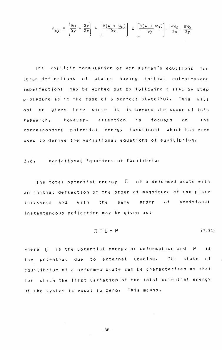
9wo 9\ _ 9x 9y
Tne explicit formulation ot von Karman's equations tor
large deflections of plates having initial out-of-plane
imperfections may be worked out by following a step by step
procedure as in the case ot a perfect plate(50). This will
not be given here since it is beyond the scope of this
research. However, attention is focus$ed on the
corresponding potential energy functional which has been
useu to derive the variational equations of equilibrium.
3.6. Variational Equations ot Equilibrium
The total potential energy n of a deformed plate with
an initial deflection of the order of magnitude of the plate
thickness and with the same order of additional
instantaneous deflection may be given as:
n = U - W (3.11)
where U "»s the potential energy ot deformation and W is
the potential due to external loading. Thr state ot
equilibrium of a deformeo plate can be characterised as that
for * h i c h the first variation of the total potential energy
of the system is equal to zero. This means,
xy 3u 9v 3y + 3x I )
3 (w + w0) 9x
9 Q + Wp-)" 9y
-38-
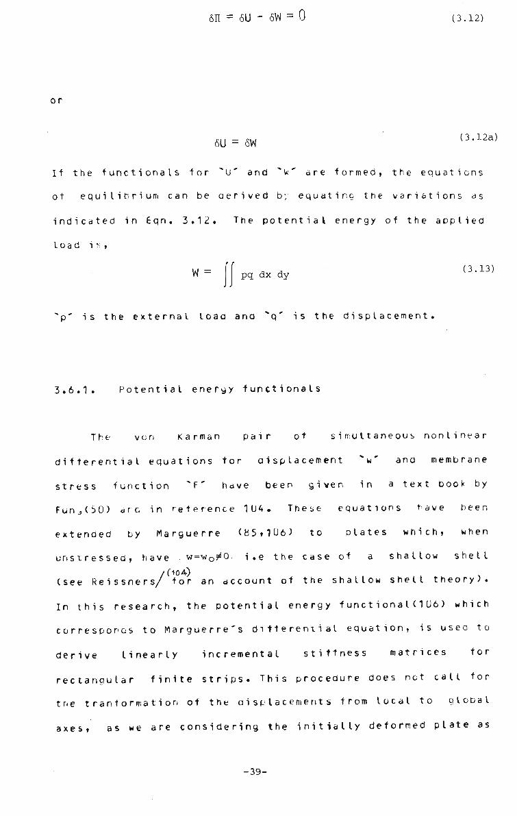
sn = 6U - 6W = 0 (3.12)
or
SU = 6W (3.12a)
If the functionals for "U' and " W are formed, the equations
ot equilibrium can be aerived by equating the variations as
indicated in Eqn. 3.12. The potential energy of the applied
load i * ,
W = pq dx dy (3.13)
"p' is the external load and "q' is the displacement.
3.6.1. Potential energy functionals
The von Karman pair of simultaneous nonlinear
differential equatidns tor displacement "w' and membrane
stress function "F' have been given in a text book by
FunJ)(50) arc in reference 104. These equations rave been
extended by Marguerre (85,1U6) to plates which, when
unstressed, have . w=wo^0v i.e the case of a shallow shell
/Oo4) , (see Reissners/ for an account of the shallow shell theory).
In this research, the potential energy functional (106) which
corresponds to Marguerre's differential equation, is useo to
derive linearly incremental stiffness matrices tor
rectangular finite strips. This procedure does net call for
trie tranformation of the displacements from local to global
axes, as we are considering the initially deformed plate as
-39-

an assemblage of shallow-shell strips*
The potential energy of deformation tor a plate strip
with large deformation, written in terms ot the deflection
and strains ot the middle surface can be obtained using the
following steps(127,143) .
(i) Strain energy due to bending - Ub
The strain energy in bending (8U) per unit area ot a
deformed plate, u'- is expressed simply in terms of the
principal moments Mi> and «2 and the principal curvatures
Xi and X2 as»
U' = 2 (M1X1 + M 2 X2 )
The principal moments and curvatures are related by
(3.14)
X l = (M1 - VM2)/D'
X2 = (M - VM1)/D'
(3.15)
where V is the Poisson's ratio, and
2v Eh3
D' = (1 - VZ)D = Y J (3.16)
in which D is the bending rigidity.
On substitution,
u' = \ D(x" + 2V \\+ x22) (3.17)
The total strain energy ot bendiny U ^ , is obtained by
integrating U over the entire plate. In case of plates with
-40-

constant ri g i a i ty ,
Ub U' dxdy (3.18)
or
"b-i t 2 2 (Xx + 2v X lX 2 + X2 )dx dy (3.19)
Rearranging Eqn. 3.19 leads to,
ub = i D (Xj + X2) - 2(1 - v)XlX2 dx dy
1. 2
j J
D 2 2 2 2 2
ft w 9w, ori w8 w 9 w e - T + —2") - 2(l-v){-T - T . .9x 3y 9X 9y
(3.19a)
2 ,3 w *, , , C37§7) }dx dy'
The operator v2 i s defined as,
32 32
3x* + 3y7 V2 = £-, + £_. (3.20)
•(Following the invariant relationship(80) v Y - v2 =v y ) AA A A-LA2
ii) Strain energy due to stretching - U
The strain energy due to stretching (n) of the plate may P
be written as(80 ) ,
-41-

u = Eh
P 2(l-v )
2 2 1 21
x y x y 2^ } xy dxdy
Eh
2(1-0
ff 2 2 e + e_, +2 e e - 2(l-v)e e +
x y x y v -1 x y
^ (1-v) • dxdy (3.21)
Eh
2(l-v ) 7— (e + e ) -
^ x yJ Eh
(1+v)
1 2 e e - — e x y 4 xy I
dxdy
D 12 z 12 •=• — 2
ei " 2(l-v)D — „ e dxdy 1 h x h
whe re
e, = e + e 1 x y
1 2 2 x y 4 xy
(3.22)
The inplane strains of the middle suface €x,e"y and €xy have
beer! given in Eqn. 3.9 for a perfect plate and in Eqn. ?'. 10
for one with initial imperfections.
-42-

i i i ) P o t e n t i a l e n e r g y a u e to a p p l i e d load - w:
The p o t e n t i a l e n e r g y d u e t o a p p l i e d l o a d i n g ( p ) , i s
g i v e n a s ,
W = - qp dx dy (3.23)
where a is the displacement.
It there is no work aone at the boundaries ot the plate,
the total potential energy 0 may be obtained as,
b p (3.24)
Substituting Eqns. 3.19a and 3.21 into 3.24 yields,
» - ! 2 2 12 21
(V w) + -jr e-h
2C1-V) 12 —5- e, h '
3 w1
2
3x
r 2 i
3 w . 2 i^y .
-r,2 1 3 w 3x3y,
2
dx dy
(3.25)
Corresponding to the middle surface strains the miadle
and
required) by the following equations.
surface stresses °x a„ T xy can be evaluated (if
(1-v )
ay- ~r d-v )
xy " 2(l+v)
e + v e x y
ve + e x y
xy
(3.26)
-43-
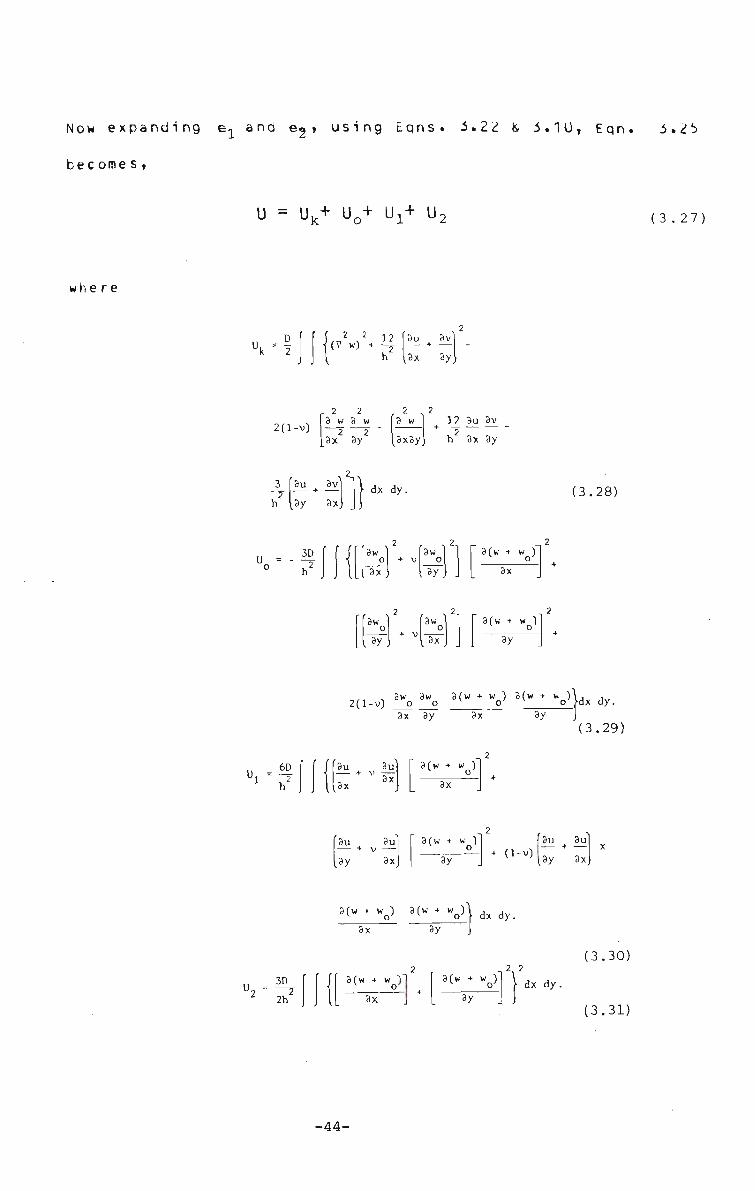
Now expanding e^ and e<j , using Eqns. 3.22 ii 3.10, Eqn. 3.25
become s,
whe re
U = Uk+ U0+ Ux+ U; (3.27)
k 2
2 2 12 [Su x 3v
h lax 3y
r 2 2
2(1
3 T h
-V)
l»y
3 w 3 w 2 2
_3x 3y
3X.
2n
)
r 2 N 2
3 w t3x3y
12 3u 3v 2
h 3x 3y
dx dy. (3.28)
h2
3w , 0| + V
3x
r szi 3w | ' °
Ux) . 3fw + w 1
o 3x
Taw o
LI ay
2
+ V '"of 3(w + wo)
~ 3 y
2(l-v) 8wo ! % 3( w + V 3(W + V>)dx dy. 3x 3y 3x sy
(3.29)
6D
h 2.
' ' (f 11
3u 3u + V -r— 8*
3x
3(w + w )
3x
'3u 3ul [ 3(w + w ) - + v — o
dy 3xJ [ 3y + d-v)
3u 3u
L3y 3x
3(w + w ) 3(w + wn)
3x 3y o' \ dx dy.
3D
2h
3(w + wo)
3x
2 . ,2, 2 3(w + w ) "• <r
3y
dx dy.
(3.30)
(3.31)
-44-
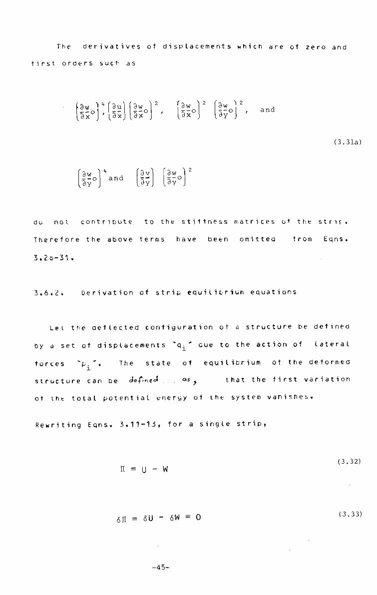
The derivatives of displacements which are of zero and
first orders such as
f3w. VfSu
k3x°]'l3x 3w 3x°
(3w 1 3w I2
and
(3.31a)
3w
135° and
3v [3y
9w
l9y J
do not contribute to the stiffness matrices ot the strif.
Therefore the above terms have been omitted from Eqns.
3.20-31 .
3.6.2. Derivation of strip equilibrium equations
Lei the deflected configuration ot a structure be defined
by a set ot displacements ^q^ ' cue to the action of lateral
forces *p The state of equilibrium ot the deformed
structure can be define J <*s that the first variation
ot the total potential energy ot the system vanishes
Rewriting Eqns. 3.11-13, for a single strip,
n = u - w (3.32)
sn = 6U - 6W = o (3.33)
-45-

w = pq dx dy (3.34)
where the external load p is constant in the absence of
boundary forces.
Summing the strain energy tor the entire structured.e.
all strips) Eqns. 3.33 and 3 34 can be combined in the
following form,
X«u J6W = ISJ p.q. dx dy (3.35) 1 1
ing/partial derivati Taki
displacement parameter, qi
ve with respect to q; , any single I
^6q.
f f p. dx dy i'i (3.36)
where
p = p. dx dy (3.37) i J J J-
'U' i<. the strain energy ot the plate due to the bending and
in-plane deformations and as such is a function ot q^
Let A oenotes the increment in these quantities, for the
structure remains in equilibrium, we have,
L 3(q^ + AqJ L I
(3.38)
It 0 and q. are regarded as constant and only 0 and q. are
-46-

varying, then
I 3(U + AU) = E 3AU
d(q.+ Aq.) ^3Aq. v l l l
(3.39]
and
L 3Aq. / i i (3.40)
Equation 3.4 0 provides the oasis tor what is called the
incremental methdd. If SAq. represents small variatidn in i
Aa. then Eqn. 3.40 can be written as,
l& Aqi 3AU
^Aq.J = I (Pi + AP.)6Aq. (3.41)
where Au will contain terms which are linear, quadratic and
higher order functions of qi . The oifterentiat ion of linear
terms leads to constant values which must be equal to pi ,
differentiation of quadratic terms yields linear functions
of q. which are equated to P^. The higher order terms in
q. are neglected to make the problem incrementally linear
(Eqn. 3.3la). Eons 3.28-31 are the expression of 0 in terms
of deflection q-. Therefore the change in strain energy
from u to U+AU can be achieved by replacing u,v and w by u •
Au/V+Avard w+Aw respectively ana subtracting U from 0+ A0.
The detailed expression ot 0+Ao (in terms ot q.+Aqt) is
extremely lengthyd06) and not be pursued here. By
performing some algebraic operations on the expressions for
(0+AO) and 0, cancelling the terms equivalent to P$ in
equation 3.41 and then neglecting the terms ot third and
-47-

higher orders in qi,the final expression corresponding to
Ap-4Aqi may be ortained ( 1 06).
Alternatively, the expression tor APiSAqi has been
obtained directly by differentiating 0( Aq^) twice with
respect to t,Qi and negelecting higher order terms (Eqn.
3.31a) mentioned above. This procedure is usee in what
follows to obtain the incremental stiffness matrix of a
tinite strip.
3.6.3 . St i ffness matrix
The expression tor the strain energy as a function ot
incremental displacement Aqi , may be traced from Eqns.
3.28-31, which is given as:
U(Aqp = V ^ ) + U^Aq^ + U^Aq.) + U2(Aq.) (3.42)
D Uk(Aq.) = -2
2 12 2
CAwxx + Awyy} + "2 CZux + *V +
2(l-v) Aw Aw - Aw + xx yy xy
1| Au Av - 3(Av + Au ) h2 x y *• y xJ
dx dy
(3.43)
-48-

U0(Aqi) = 3D fw + V w )
*• o x oy •* Afw+w )
w + V w oy ox
Afw + w ) v o'y
2(l-v) w0 x w0 y
A(W + Vx A(W + WoV| dX dy' (3.44)
h (Au + vAv ) K x y
Afw + w ) ^ o x
fAv + vAu ) Afw + w )y *• o
(1-v) CAuy + Avx) A f w + w ) A f w + w ) *• o x v o y
dx dy.
U (Aq ) = -j-
^ 1 h
2_
A f w + w ) + Afw + w ) v oyx o y
dx dy.
(3.45)
(3.46)
-49-
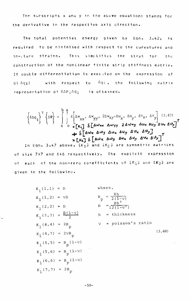
The Subscripts x ana y in the above equations stands for
the derivative in the respective axis direction.
The total potential energy given by Eqn. 3.42, is
required to be minimised with respect to the curvatures and
in-flane strains. This simplifies the steps tor the
construction of the nonlinear finite strip stiffness matrix.
If aouble differentiation is execJted on the expression of
U( Aqi) with respect to Aqi , the following matrix
representation of 6APiAq^ is ottained.
6Aq. V U -b a
Aw_, i w w , 2Awxy,Aux, Auv, Avx, Av XX yy y
(3.47)
o 'o x^icH &[>*>«* A*°»* 24*>*3 Au* 4U3 fli*« 6*,J
^ S[A*>* t<*3 &ux Auy &V*. &*yj T
In Eqn. 3.47 above, LK^3 and LK2J are symmetric matrices
of size 7x7 and 6x6 respectively. The explicit expression
of each of the non-zero co-efficients of LKX] and C K 2 3 are
given in the following.
K 1(1,D
K1d,2)
K (2,2)
KL(3,3)
K. (4,4) 1
K1(4,7)
K (5,5)
KL(5,6)
K1(6,6)
D
VD
where,
= D
p(l-v) 2
= 2B P
= 2VB
= B (1-V) P
= B d-V) P
= B (1-V) P
Eh Bp 2(1-V)
Eh3
D =• -12 (1-V)
h = thickness
V = poisson's ratio
(3.48)
K]_(7,7) 2B
-50-
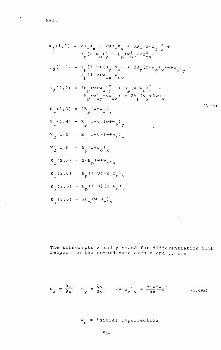
and,
K 2(1,D 2B u + 2VB v + 3B (w+w ) 2 + P x p y p o, x
B (w+w ) - B (w2 +Vw2 ) o y p ox oy
K2(l,2) B (1-V)(u +v ) + 2B (w+w ) (w+w ) p y x p o x o y
B (l-V)w w p ox oy
K2(2,2)
K2(l,3)
3B (w+w ) + B (w+w ) 2
p O y p o x B (w +VW ) + 2B (v +2Vu
p oy ox P y 2B (w+w )
p o y
x (3.49)
K 2 d , 4 ) B (1-V)(w+w ) p ° y
K2(l,5) = B (1-V)(w+W ) P o y
K2(l,6) B (w+w ) p o x
K2(2,3) = 2VB (w+w ) p ° y
K2(2,4) = B (1-V)(W+W ) p o x
K2(2,5) = B (1-V)(w+w ) p o x
K2(2,6) = 2B (w+w ) P o y
The subscripts x and y stand for differentiation with respect to the co-ordinate axes x and y, i.e.
u = 3u_ 3x; u =
3u 3y; (w+w )
o X
3(w+w ) "~7\ °
wx (3.49a)
w initial imperfection
-51-

Trie incremental curvature and inplane strain vectors of the
torm; lSJ{Aq<; in Eqn. 3.47, which are chosen tor the
minimisation procedure can be expressed in terms ot the
nodal line displacement parameters, using the following
expressi ons.
For the I i nea r part,
5 [Aw Aw Aw Au Au Av Av ]T= o J s J U q } (3.50) L xx yy xy x y x yJ u 1J
For the geometric stiffness part,
6 [Aw Aw Au Au Av Av ] T = 6 [ S2 ]<
A <^ *- V XT v \r V XT •* x y
(3.51)
where IS 3 and [S 3 are the coefficient matrices, and these
are obtained by appropriate differentiatidn of the chosen
displacement function(EMn. 3.1) ot the finite strip. Since
Eqn. 3.47 holds good for any value of (SAq/it follows that:
F
APr = [V + Cl Kn*]] M (3.52)
CS1]TCK1][S1] dx dy (3>53)
K n£
ra [S2] [K2DCS2] dx dy (3>54)
o •'o
The above matrices(CK#J and CK „J) are called the linear 3c n£
-52-

and geometric strip stiffness matrices res v. ectively. Once
the strip discretisation ot a structure is set up the strip
stiffness equations can be assembled to form the overall
structural stiffness equations, which follows that,
I CAP} = I lH1 + [Kn£] IA*} (3.55)
I[K. ]{Aq) L L incJ
(3.55a)
whe re
n ^ L inc-* L inc-' structure h '-, inc-'
i = l
(3.56)
n equals total number of strips in a structure.
incJ structure
The assembly of the element stiffness matrix is
pertorrrec such that the band width ot the structural
stiffness matrix will a minimum. Here the procedure
suggested by Cheung(25) has been used to form the [Kinc],
matrix derived above.
Eqn. 3.55>a is however non-linear and therefore an
incremental, and a combined incremental and iterative(step
iteration) methods have both been used to solve these
nonlinear stiffness equations. The incremental method was
found to be suitable for plates having initial imperfections
while the combined procedure(step iteration) is valuable for
the perfect plates(Sec. 6,1), The theoretical basis ot the
incremental procedure and also its extension to incorporate
an iterative scheme will be presented in the subsequent
-53-

chapters ( Sec . 7.2-3).
-54-

4.
CHAPTER 4
COMBINED GEOMETRIC AND MATEHIAL NONLINEARITY
4.1. Combined Nonlinearity
4.1.1. Oenera I
The ultimate strength of a plate or plated structure is
a function of its nonlinear behaviour under increasing lead.
To study the behaviour of thin plates ana related structures
such as stiffened plates and box girder structures,
consideration of both geometric ana material nonlinearities
is essential.
Geometric nonlinearity is caused by excessive
deflection; material nonlinearity is the result of a
non-linear stress-strain relation. For most structural
materials, after a certain stage of loading, the
constitutive relation is no longer governed by a constant
elastic property matrix, but depends on the state ot stress
at each point over the structure. This tact together with
the history dependence of the strains at different points of
a structure make even the solution ot a simple problem a
formidable task.
-55-

The problem of combined non-linearity considered in this
thesis is the geometric non-linearity caused by excessive
deflection accompanied by plasticity ot certain portions ot
a structure where stresses have reached the yield point as
defined by some established theories such as vun Wises'.
The method ot treating geometrically non-linear problems
has been discussed in Chapter 3. Material non-linearity
associated with metal plasticity is considered here. It has
been found by previous researchers(145) that plates, shells
and plated structures can withstand further loacing even
when the stresses at critical points have reached the yield
stress. This justifies the present investigations to
assess their reserve strength which may lead to
cost-efficient construction.
C.1 .2. Assumpt i ons
The following assumptions are made in formulating the
large deflection elasto-plastic analysis presented
hereunder:
i) Assumptions i,ii,iii,iv and vi made in the elastic
analysis listed in Section 3.5.2 are also made here.
ii) /material is isotropic in both elastic and plastic
ranoes .
The iii) /material is homogeneous.
iv) The stress-strain relationship is the same both in
tension and in compression (i.e. Bauschinqer's effect
i <•; neglected).
-56-
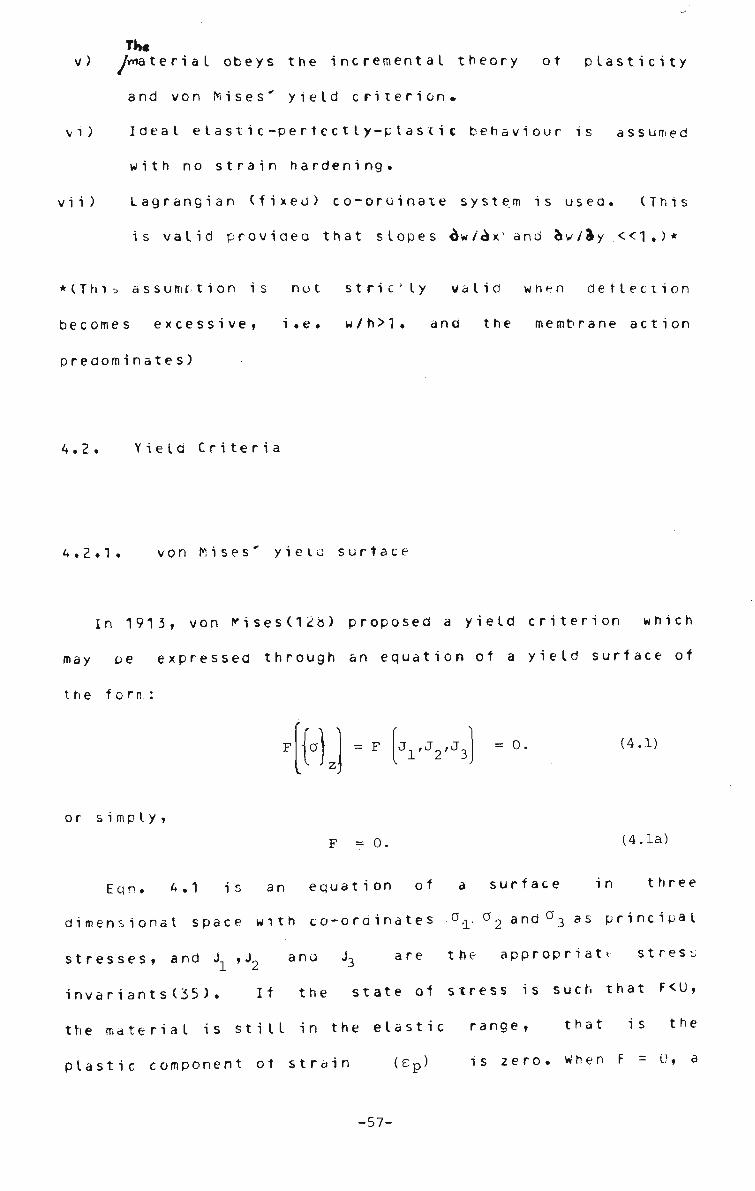
v) /rrtaterial obeys the i n c r e m e n t a l theory ot plasticity
and von Wises' yield criterion.
vi) Ideal eI astic-pertectIy-plastic behaviour is assumed
with no strain hardening.
vii) Lagrangian (fixed) co-ordinate system is usea. (This
is valid providea that slopes dw/^x and &w/«ky <<1.)*
* (T h i i> assume t i o n is not strie'ly valid when deflection
becomes excessive, i.e. w/h>1. and the membrane action
predominates)
4.2. Yield Criteria
^ . 2 . 1 . von M i s e s ' yieto surface
In 1 9 1 3 , von ivises(12b) proposed a yield criterion which
may oe expressed through an equation of a yield surface of
the forn:
HI- J1'J2'J3 = 0, (4.1)
or simply,
F = 0. (4.1a)
Eqn. 4.1 is an equation of a surface in three
dimensional space with co-ordinates o,r ^2 and°3 as principal
stresses, and J ,J2 ana J3 are the appropriate stress
invariants(35). If the state of stress is such that F<0,
the material is still in the elastic range, that is the
plastic component ot strain (ep) is zero. When F = 0, a
-57-

plastic state is attained and one of the theories ot
plasticity must be used to determine subsequent plastic
behaviour under increasing stress or strain, when F>u, it
means that the increment ot load is higher than what is
exactly needed for the stress to reach the yield surface;
some artifice is required in order to cope with such
situations. Zienkiewicz(33) has proposeo an iterative
method to deal with the problem; the same has been used in
the present study (see also the computer program PLAST on
Mic ro-f i che)
The von Mises' yield criterion assumes that yielding is
caused by maximum distortional energy. Alternatively the
yield surface * F ' (Eqn. 4.1a) is mathematically expressed
as(35) :
F = J D 2 ~ °0 = 0 (4.2)
where 0 o is the experimentally determined yielc stress in
simple shear and J is the second deviatoric stress D2
invariant. In terms of stresses, von Mises' criterion may
be written as,
F =
2 2
J (ax • °y] + 1 [°y " °z) + T (az " °x]
(4.3)
2 2 3T + 3T + 3T
xy yz * zx
- o 2 = 0 o
-58-

In the two dim e n s i o n a l situation and where az,Tyzr and T Z X
are neglected, the above expression reduces to,
\J (ax ~ ay) + I °y2 + \ \ + * xy = o (4.4)
2 2 2 a +o -oo +3T x y x y xy
= a (4.5)
Alternatively a plastic potential f may mathematically be
def ined as ,
or
<?x2 + -ay2 - tffc 0 y + 3fxy:
f =
eg-a
. a eg
(4.6)
(4.6a)
where
°eq = ^x + J-^x^y+BT^ (4.6b)
The m a t h e m a t i c a l r e p r e s e n t a t i o n ot other yield criteria
such as those of Tresca, Coulomu and Mohr-Coulomb are
relatively simple and are available e Isewhere (35 , 94 ) .
-59-

4.2.2. I l y u s h i n ' s yielu criterion
In order to have a more accurate s o l u t i o n , von M i s e s '
yield criterion is usually chosen, wherein the stresses are
monitored over the surface ana depth ot structure unaer
investigation. Thus the procedure demands more computer time
which may not always be a design office proposition in terms
of costs. An '"area approach' based on Ilyushin's yield
criterion can provide an economical solution. A brief
description of/Ilyushin yield criterion and its subsequent
developments (32,87) is presented.
In 1948 Ilyushin(62) used von Mises' yield function to
derive a complex yielo surface tor a thin shell.
Subsequently he proposed a simple but approximate form ot
yield surface (Eqn.4.13). This forms the basis of the
present formulation.
Ilyushin employed the deformation theory to derive his
yield surface, F given in Eqn. 4.7 and CrisfieId(33) adopted
this surface in conjunction with a flow approach. The same
Mlow function' (Eqn. 4.13) is assumed in the present work.
The main assumption used in the derivation ot the yield
surface is that the equivalent.stress tJ (Eqn. 4.6b) is at
yield point(cr), as defined by von Mises' yield criterion, o
throughout the full depth of the section. In the bending
dominated situations, this state is only strictly attainable
at an infinite equivalent plastic curvature. For many
problems this is not a serious drawback. Such an assumption
is* after all the basis for ptastic mechanism analysis of
frames, and yield-line analyses tor slabs. However, it a ay
-60-
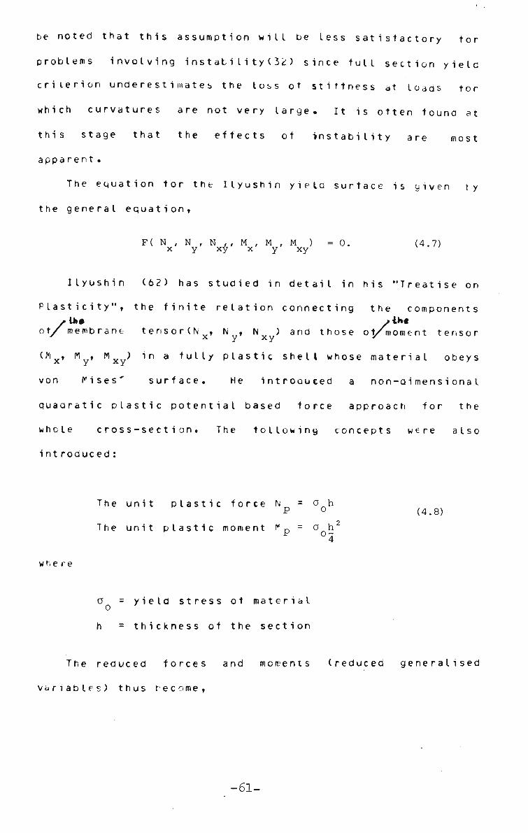
be noted that this assumption will be less s a t i s f a c t o r y tor
problems involving instabi I ity ( 32) since full section yield
criterion underestimates the loss ot stiffness at loads tor
which curvatures are not very large. It is often found at
this stage that the effects of instability are most
apparent.
The equation tor the Ilyushin yield surface is given ty
the general equation,
F ( N , N , N , , M , M , M ) = 0 , x y xy x y xy
(4.7)
Ilyushin (62) has studied in detail in his "Treatise on
Plasticity", the finite relation connecting the components
of/ membrane tensor(Nx, N , Nx ) and those of/moment tensor
(Mx, My, M ) in a fully plastic shell whose material obeys
von Mises' surface. He introouced a non-oimensionaI
quaaratic plastic potential based force approach for the
whole cross-section. The following concepts were also
int roduced:
The unit plastic force N = a h
The unit plastic moment f* p = ah' 4
(4.8)
where
a = yield stress ot mate rial
h = t h i c k n e s s of the section
The reduced f o r c e s and moments (reduced generalised
variables) thus become,
-61-

n =
m =
N x . N ' P
M x ; M P
N ny = _x y N
P m =\ y M
P
n xy
m xy
N xy N
M = xy M
(4.9)
The non-dimensional quaoratic forms are,
2 2 2 % n = n + n + n n + 3 n ^n x y x y xy
> 2 2 2
n = m + m + m m + 3 m Sn x y x y xy
(4.10)
O = m n + m n mn x x y y
1 -m n 2 x y
-m n + 3m n 2 y x xy xy
in which subscript n indicates membrane actions and m
denotes bending moments.
Massonnet(87) proposed a simplified procedure to define
yield surface of hyper structures of the following form:
F( V V nxy' V V V = °' (4.11)
From Eqns. 4.10 and 4.11 a curve between Qm and Qn can be
plotted(87) and the approximate relationship (straight line)
between them can be estaolished as,
Q + Qm = x
n m
(4.12)
This approach was further advanced by Cristie I a (33) who
incorporatea the term Qmn (Eqn.4.10) to define the yield
-62-

surface. i^assonnet(87) omitted thf U n m ' term to simplify the
classical formulations (Eqn. 4.12) of the problem. in the
present stuoy expressions derived by Cristield(33) are used.
The approximate yield surface (Ilyushin's) ot a shell using
deformation theory, is ^iven as,
- N 4sMN 16M f = TT + 3 2 + -IT—2 (4-13)
ha 3h a h a . o o o
where a. is the uniaxial yield stress and N,M and MN are the o
quaoratic stress intensities given oy,
N = N/ + Ny2 - Nx Ny + 3Nxy
2
M = Mx2 + M y
2 - M x M y + 3Mxy ( 4 1 4 )
MN = Mx Nx + My Ny - i Mx Nx + 3 Mx y N x y
s = 77 77 (4.15) MN
4.3. Plasticity
-63-

4.3.1. beneral
Two m e t h o d s of treating p l a s t i c i t y are presented herein.
The first uses von Mises' yielo criterion (Sec. 4.2.1)
> involving/ volume integral and is referred to as the 'volume
approach'; the second called the 'area approach'
incorporates the approximate yield criterion given by
Ilyushin (Sec. 4.2.2) which is based on six generalised
stress resultants in the shell (N » N , N and M ,M . M ). x y xy x y xy
The volume and area approaches are used to formulate the
tangential elasto-plastic modular matrices.
4.3.2. Volume approach
The normal stresses perpendicular to the Diane ot the
plateCi.e. z-axis) are neglected in volume approach.
Consequently, at any level z(Fig. 8.32) plasticity which is
governed by von Mises' yield criterion, can be represented
as,
2 2 2
(£) = -VC°X + °y ~ °x°y + 3V } " * (4-16) z a
o
where (f) is plastic flow at level z. z
For convenience this plastic flow is designated as f.
In order to satisfy this yield criterion the plastic flow f,
has to remain on the yield surface, then the following
differential is valid(33).
-64-

6f = o. (4.17)
or {if H • ° (4.18)
where Aa is t h e generalised incremental stress.
The Prandtt-Reuss (58) flow rule gives,
w. •«. (4.19)
where X is the proportionality constant and is a positive
scalar quantity. The incremental stress-strain law may be
writtenas,
R= [ E 1 !ft} - K ) (4.20)
where
LE3 is the elastic modular matrixlEqn. A1.25),
(Ae } i s t h e t o t a l incremental strain at level z, t z
{Ae } "*s Plastic part of the total incremental strain P z
at leve I z.
The increment of stress and the increment ot total strain at
-65-

any point z, may be related as.
{*,} - [EVJ f«t}_ (4.21)
It the total incremental strain, {AE } is assumed to t z
vary linearly over the thickness of the plate, the following
expression can be written.
K) t • K} • *K} (4.22)
where iAet) defines the middle surface strains at z=o
(miodle plane, Fiy. tt.32) ana where the negative
incremental curvatures (Ay) may be expressea as,
W •
2 - 9 Aw
3x 2 3 Aw
ay2
2 8 Aw 3x3y
- 2
(4.23)
and ,
Le\ = Ue\ + [TS3 |AS| + JAIJ (4.24)
The details of the elements of the strain vectors - t ^ } ,
£e + } » ITSJ and <AS> are given in the next section.
[E*{O"}] in Eqn. 4.21, is called the tangential
-66-

elasto-plastic moouiar matrix and is a function of the
current stress level at z(Fig. 8.32) In the case ot zero
strain hardening, this may be expressed as,
E*(a) z
E m - [«] w' (4.25)
r = A + W® {"}] (4.26)
[•]-{%W (4.27)
The general expression tor the tangential elasto-plastic
modular matrix including material strain hardening is given
in (Eqns . Al .9).
The incremental stress resultants LAN} and 1 A*~> are
defined as follows,
AN =
AM =
h/2
h/2
h/2
h/2
iho\ dz
i\to\ dz
(4.28)
Combining Eqns. 4.21,4.22 and 4.28 yields,
-67-

{<*} - CC\ ft} * M v ft}
(4.29)
{AM} = [cd]y {A^} + [D*]y{AXtj
where [c*] l*D*l an<j Tcdl are the tangential elasto-plastic v' L Jv L Jv
modular matrices that relate the strains to the generalised
stress resultants and can be expressed as follows:
[c*]v = I 03*0)] dz '
[D*j .
[cd] =
[E*(a)]zz2dz
[E (a)]z zdz
(4.30)
4.3.3. Area approach
The approximate yield criterion according to Ilyushin
can be represented by Eqns. 4.13-14. In order to satisfy
this yield criterion the plastic flow *f, defined by Eqn.
'•.I 5, has to remain on the yield surface (same as in volume
approach, Eqn.4.6a). Therefore the following differential
holos good,
6f = o (4.31)
or
-68-
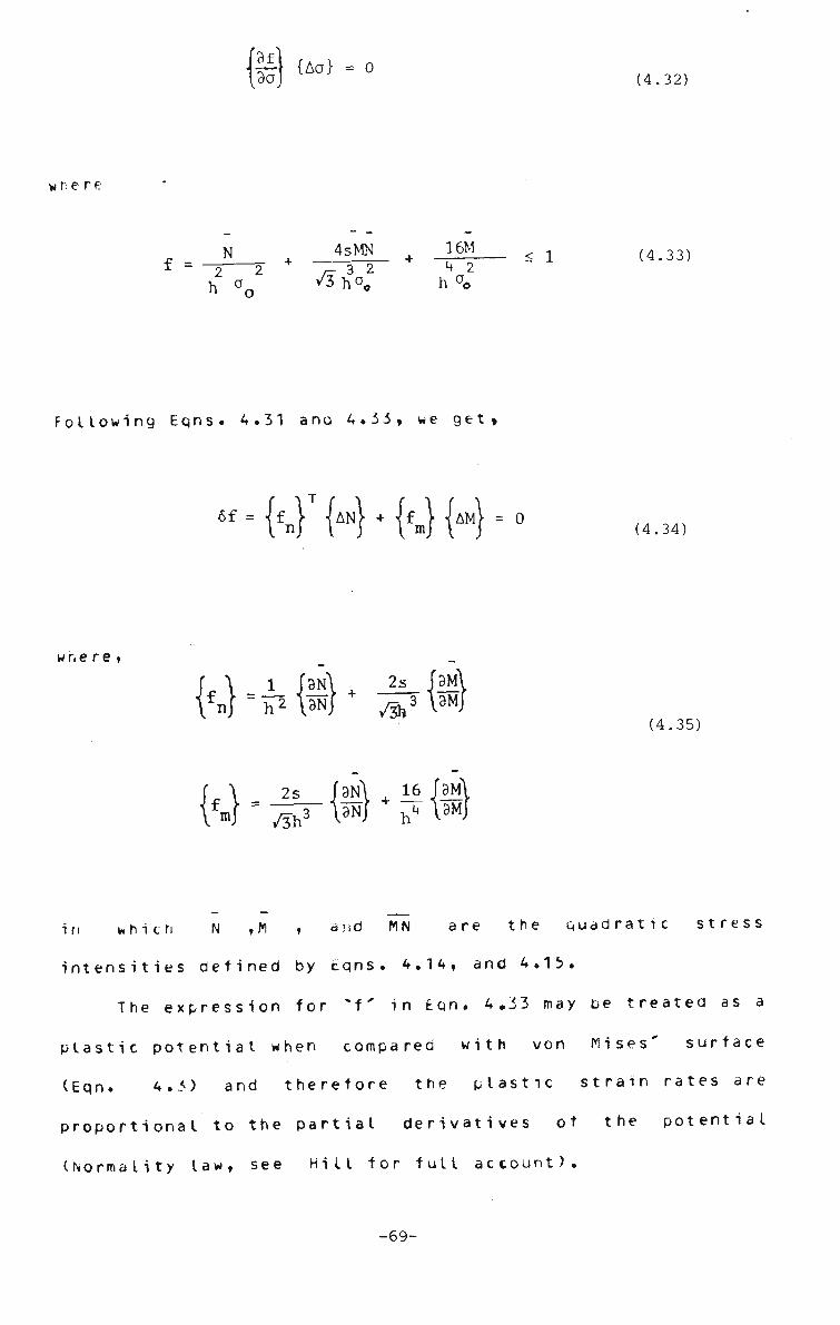
{§}{ao) • °
where
N . 4sMN _im 1 (4#33)
f = -5 2 /r32 \2 h aQ /3 h°"0 h
ao
Following Eqns. 4.31 ana 4.33, we get
«f - {fj" {AN} • {fJ {AM} . 0
where,
\fn) " h2 W 2s
+ /3h3
W"^r{«^{«
(4.34)
(4.35)
in which N ,M , and MN are the quadratic stress
intensities defined by Eqns. 4.14, and 4.13.
The expression for *f* in Eqn. 4.33 may be treated as a
plastic potential when compared with von Mises' surface
(Eqn. 4.3) and therefore the plastic strain rates are
proportional to the partial derivatives of the potential
(Normality law, see Hill for full account).
-69-

f P} •x w
Kl •x W (4.36)
{f } and {f } are defined by E q n . 4.3b and X is a m ri
proportioniIity constant.
The p r o c e d u r e of f o r m u l a t i n g the incremental s t r e s s - s t r a i n
relationship in this (area) cast is very similar to the
volume approach and is given in Appendix I.
The relationship between incremental stress and
incremental strain may oe rewritten from Eqn. A1.22 as,
f} = CC*]A f J + "A f *) f} - C<*£ ft} + tD*]A ft}
(4.37)
The above e q u a t i o n s have the same form as the parallet
equation in the volume approach(Eqn. 4.2V).
The tangential elasto-plastic moaular matrices CC*3, LD ^3
and Lcdl (Appendix I) are functions ot the six generalised
stress resultants -CN> and <M> of the structure. The
elements ot these stress vectors can be obtained by Eqns.
4.5d and 4.54 respectively.
-70-

4.3.4. D i s c u s s i o n
The m a t h e m a t i c a l f o r m u l a t i o n s of the volume and area
approaches are presented. The volume approach is far more
accurate than the area approach, but the computing costs are
dbviously much higher. In view of this, the area approach
is often used as an initial guide and the volume method is
employed only when required.
Strictly, the elasto-plastic investigations in plates
using the volume approach, should be preceded by the
so-called *area' method. In the present research the
investigation was initiated in the two directions(e.g. area
and volume), in order to prove the validity ot the finite
strip method in both the cases. A computer program has also
been developed to solve elasto-plastic problems in plates
using the area approach but further investigation has been
discontinued to limit the scope of this thesis to a
reasonable size. However a thorough investigation is
carried out to solve large and small deflection problems of
plates incorporating the volume approach.
Recently some modification to the area method has teen
proposed(31) to make it suitable for problems such as
buckling analysis of plated structures.
4.4. Variational Equations of Equilibrium
In the absence of body forces the potential energy of
the plate can be written a s (3 3) .
-71-
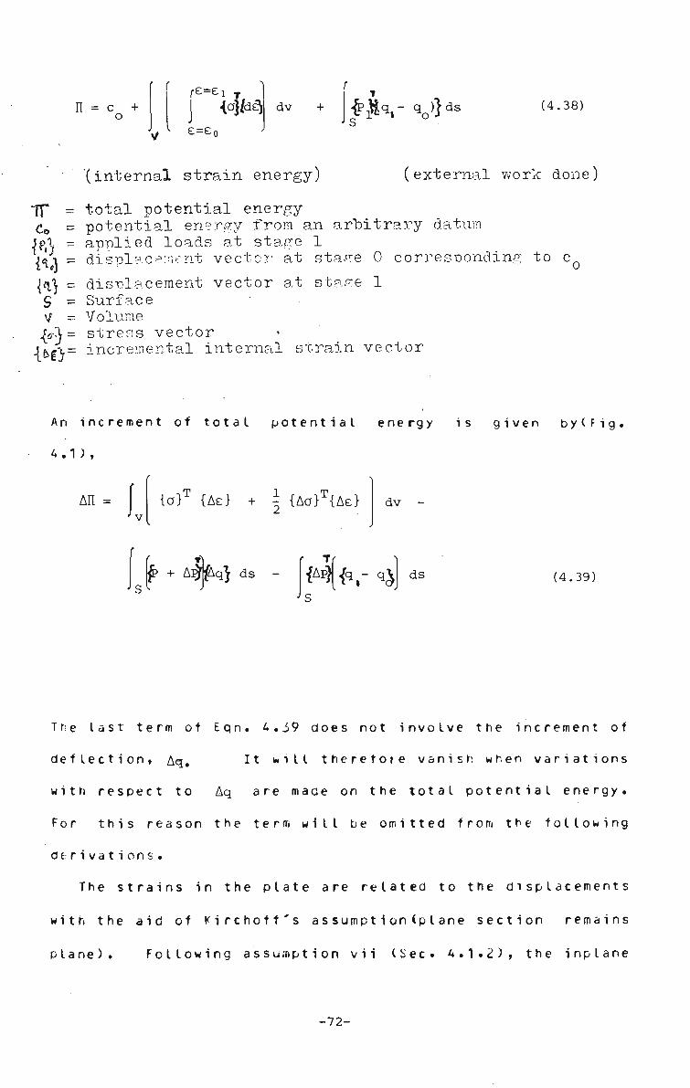
r r
n = c + o
r£=£i {of/del
*> e=e0
dv + (4.38)
"(internal strain energy) (ext ernal work done)
If* = total potential energy-Co = potential energy from an arbitrary datura 5pX = applied loads at stage 1 fax = displacement vector at stage 0 corresponding to c( {aj = displacement vector at stage 1 S = Surface V = Volume {JA = stress vector {t>6\ = incremental internal strain vector
An increment of total potential energy is given bylFig
4.1 ) ,
An = {of {Ae} + i {Aa}T{Ae}
^ + A^fAq} ds
dv -
r T {AP} £ r qj ds (4.39)
The last term of Eqn. 4.39 does not involve the increment of
deflection, Aq. It nill therefore vanish when variations
with respect to Aq are made on the total potential energy.
For this reason the term will be omitted from the following
derivations.
The strains in the plate are related to the displacements
with the aid of Kirchoff's assumptionCpIane section remains
Plane). Following assumption vii (Sec* 4.1.2), the inplane
-72-

displacements (Eqn. 3./) at any depth *z' nay be expressed
as,
u = u(x,y) - z -5— z ox
. , 3w v = v(x,y) - z r— z oy
(4.40)
w = w(x,y) z
u,v, and w are the deformation of the middle surface,
x-ylFio 3.2). These equations have the same form as in Eqn.
3.7 and remembering that u(x,y), v(x,y)(Eqn. 3.7) can be
represented as u and v, therefore these may be rewritten as,
z
V
z w z
=
=
u
V
w
- z
3w 3x
3w 3y- (4.41)
The strain at any depth *z' may be written as
{e} = le} + {e > + zix> z
(4.42)
whe re ,
{£} =
3x
3y_ 3y
3u 3y_ oy 3x
(4.43) U+}
2 dx
2 3yJ
,3w 3w. l3x 3y}
(4.44)
-73-

and
W
32w
32
3y (4.45)
-2 32
v? 3x3'
and the incremental strains at any point z, are given by,
JAe} = Li\ + [TS] /AS} + |AE+} + Z/AX} (4.46)
where {As} (Ae } ana iAx> are obtained from {el, {e }
and {/) by replacing u,v and w by their increments Au, Av
and Aw respectively. The incremental slope vector! As > ano
slope matrix CTSD are given as,
H -' 3Awl
3x [ 3Aw 3y
(4.47)
[TS] =
3w 3x 0 9w 3y
0 3w 9y 3w 3x
(4.48)
-74-

convenient to rewrite E q n . 4.46 in the following form,
JAe} = JAeJ + |AE+} (4.49)
{Ae } = {Ai} + [ T S ] { A S > + z{Ax} ( 4 ' 5 0 )
i ch ,
{Ae } contains all linear functions ot the generalised
strain increments and
{Ae } contains the non-linear t e r m s .
4.29,46-49 are substituted into Eqn. 4.3V and the
form ot All is as follows,
An i AEr CC
NT [D*]
2-AE^ [cd] •
*] | A E | + JAsj [TS]T [C*] | A S |
Axt| + 2JAEJ [C*][TS] |AS| +
Axt] + 2 JAS • [TS]'[cd]MXt dA
Nr {{AI\ + [TS] AS + M AX dA
(U + AU)Au + (v + AV)AV -
{AS} [N+] {AS} dS
(W + AW) Aw dA
A2.23 (4.51)
•75-

(4.51)
where,
N.
f+h/2
-h/2
dz z
(4.52)
N
N
N xy
and
[N+] = N N x xy
N , N «-xy y -i
(4.53)
and the total bending moroentlfO acting on a section is given
by, h/2
{M} = z {a} dz z
(4.54)
-h/2
For the details of the intermeoiate steps for the
formulation of Fqn. 4.51 the reader is referred to Appendix
II.
4.5. Finite Strip Equilibrium Equations
The change in potential energy (Eqn. 4.51) of the whole
structure is taken as the sum of changes of potential energy
ot the inaividual strips. Thus,
-76-

n An = I AH.
(structure) 1 (strips)
(4.55)
n = total number of strips.
The expression for An. comprises of the strain vectors
given ty Eqns. 4.43-49 and 52-54. The strain vectors are
related to the nodal line parameters expressed through shape
functions representing the finite strip displacements. The
shape functions used here define a third order strip tor
bending (A3.3) ana a linear one tor in-plane displacements
(Eqn. 6-3 ). The matrices relating the slopes,curvatures
and inplane strains are given below:
Slopes
Curvatures
W-
W-
3w 3x 3w 3y
V. J
= [B]
-2
-32w
-A a w
H
= [F] H [ 3x3y
(4.56)
(4.56)
(4.57)
(4.57)
In-plane strains (4.58)
-77-

(4-3u 3x
3u *y
3u 3y
• = [H] !u V
3v 3x
(4.58)
The elements u and v in Eqn. 4.5b, represent in-plane
displacements. Precisely the sume relationships exist
between the incremental strains (Ae) and the incremental
nodal parameters Aw, Au and Av etc. The vectors lw>, <.u>
and tv> contain the nodal line displacement parameters usea
to define the assumed displacement field of a finite strip
(Fig. 3.1). The components of these vectors are given below.
{w}
f-il e. w. 1
e. 3
.
f <\
u V
u, 1
u . V. 1
V ,
I 3
(4.59)
For a typical finite strip the displacement functions used
to represent u,v ana w can be expressed by the following
genera I equat i on,
f = I VY> I £V*)] {V (4.59a) m=l k=l
The details cf the shape functions related to a finite
scrip is yiven in A 3 .3 ^
The coefficients of the LEO, LFD and LHJ matrices used in
Eqns. 4.56-58, can be obtained by appropriate
differentiation of the above displacement functions ana may
-78-

written as follows,
[H] -
I~c u Llx
ly
c u L2x
c u c2y
iy
lx
c v C2y
C v L2x
(3 x 4m)
(4.60)
[B] . r w w w w ^lx L2x L3x L4x
'iy w w 2y 3y
( 2x4m)
, w '4y
(4.61)
[F] .
w w w w lxx ^2xx L3xx L4xx
w w w w lyy 2yy ^3yy 4yy
2C W 2C W 2C V 2C W
lxy 2xy 3xy 4xy
(3x4m)
(4.62)
m = number of harmonics
-79-

By the principle ot minimum total potential energy,
6 An = 0 (4.63)
Therefore, Eqn. 4.51 can be reduced to the following form
after differentiation as above,
|P! + |AP> - jpj = [KE] Aq (4.64)
where C K E 3. is the tangent stiffness matrix tor each strip
and is given by,
[KE] = L 1 1 J L ioJ
[fc- ] fc J I ioJ L ooJ
(4.65)
and Ck 3 , L" k 3 and C k 3 are sub-matrices defined as ii io oo
[ku] = [H]1 [C*] [H] dA
oo [F]T [D*] [F] + [B]T [TS]T [C*] [TS] [B] +
T Tr [B]T[N+][B]+ [F]T[cd] [TS] [B] + [B] [TS] [cd] [F] dA
Ckio] = [H]T[C*] [TS] [B] dA - [H] [cd] [F])dA
-80-(4.66)

where, <.AP> and t Ao> are the nodal values ot the incremental
forces and displacements respecti'-ely and may be written in
the following vectorial form.
f r { AU}5! {AV}> {AW}J
f 1 and \hq\ = •
\ J
{ Au} {Av} J Aw}
(4.67]
Note that tP> is the current vector ot the total external
forces prior to the application of incremental loads and
CP} is the internal load vector, where
«
'{oV P H {v}
tW J
(4.68)
in which
{I) = ICH]T w dA
and
« •
C[B3T [TS]T /N} + CF] {M}) dA (4>69)
iip)-if }} may be considered as an out ot balance lo ad
-81-
vector. It required iP }. can be evaluated tor a current
iterative cycle or updated only for a load step. *<.P>-<P }}
vanishes it the external forces ana the internal stresses
are in exact equilibrium at the onset ot a load increment.
In order to evaluate the elements of the tangent
stittness matrix LKE3 (Eqn. 4.65) and vector iP } in Eqn.
4.6^ integration has to be performed over an area. When the
volume approach is aoopted some of the component matrices
like CC ]w, LD ]v, CcdJ^ ana lN+] etc (Eqns. 4.30 and 4.53)
involve integration through the depth and consequently the
determination of the elements ot LKEJ in Eqn 4.65 and iP}
matrices requires volume integration.
-82-

CHAPTER 5
FINITE STRIP STIFFNESS MATRICES
5.1 . Introduction
The theory of stationary potential energy provides the
basis for formulating the finite strip stiffness matrices
for both the geometric nonlinear elastic and combined
geometric and elasto-plastic analyses. As a result, the
formulations for the two different cases differ only
slightly. The elastic analysis uses a constant elastic
property matrix and only the geometric stiffness matrix is
dependent on the deflected shape ot the structure, hence it
is updated at each load increment or at an iteration level
when iteration is performed. In the latter case, the
elasto-plastic property matrix has to be evaluated at every
stage of the loading, once the structure has yielaed at a
point; the modular matrices become the functions ot stresses
at a poi nt.
-83-

!>.2. Matrix Management Strategy
The stiffness matrix expressions in elastic and
elasto-plastic cases are rather complicated (Eqns. 3.52 and
4.64). Therefore, a systematic procedure has to be adopted
to ensure that numerical computations do not become too
expensive due to inefficient management (e.g. operations on
zero) of the component matrices. It may be mentioned here
that the computer programs written to process these matrices
are not fully optimised at this stage. The strip stiffness
matrices in the elastic nonlinear caselEqns. 3.53-54) and
the expressions related to the elasto-plastic properties and
residual loads, given fcy Eqns. 4.29,4.37 and 4.69, and in
Appedices I-II, can be obtained according to the following
strategy before any large scale matrix integration is
performed.
(i) Evaluate the coefficient matrices as required by Eqns.
3.53-54 in the elastic analysis and, in Eqns.
4.48,4.60-62 for the strain displacement relationship
in the elas topiastic case. This step requires partial
derivations ot the shape functions defining the
displacement field over a strip.
(ii) Obtain the stress resultants (Eqns. 4.52-54) for the
structure at any stage ot loading for the
e I astop lastic case.
(iii) Evaluate the geometric and elastic properties ot the
structure required by Eqn 3.48-49 tor the elastic
-84-

ana l y s i s .
It is a relatively simple task to form the component
matrices from steps i,ii and iii above. However the
numerical evaluation of the stiffness (Eqns. 3.53-54 and Eqn.
4.66 and other matrices (Eqn. 4.69) requires a long chain ot
matrix products and integrations over areas and volumes ot
the structure. The explicit expressions for'the elements ot
the final matrices are lengthy and highly complicated even
before the inteyration procedure is undertaken. The
situation becomes even more difficult to manage, with the
increase ot harmonic number(m) in the assumed displacement
function(Eqn. 3.1) of the finite strip. This is because the
coupling effects between the harmonics can no longer be
ignored. A new numerical integration procedure has been
Aim developed to deal with such f u n c t i o n s . / r e a d e r is reterreo to
>'
Section 6.2.5-6.3 for full details.
The matrix management strategy tor the ceometric
nonlinear and materially nonlinear finite strip stiffness
matrix formulations will be presented,
5.3. Geometric Nonlinear Analysis
The strip stiffness matrix tor the geometrically
nonlinear analysis is composed ot two parts, the linear
matrix CK&3 (Eqn. 3.56) and the geometric matrix [K^ 3 (Eqn.
3.57). These matrix equations can be expanded to dbtain the
explicit form ot the elements ot the non-linear stiffness
matrix. The expression for such an element however would be
-85-
very long. A l t e r n a t i v e l y , it is relatively easy to deal with
the component matrices and organise them appropriately so
that the elements of the resulting matrices can be obtained
by multiplication and numerical integration, thus avoiding
the explicit formation of the lengthy expressions
altogether. The latter approach is adopted herein.
5,4. Displacement Function
The finite strip displacement function(Eqn. 3.2) can be
rewri tten as follows,
f <x,y> = I Ym(y) I [Ck(x)] { 6 ^ to=l k=l
k m (5.1)
where
f(x,y) is t h e d i s p l a c e m e n t fielo,
[G (X)1 is shape function L k J
for a strip in x direction,
Y (y) is thp analytic function in y Direction m
s is the total number ot nodal lines in a strip
(normally s equals 2)
r is the total number of harmonics.
5.4.1. Bending d i s p l a c e m e n t t u n c t i o n ( w )
The bending d i s p l a c e m e n t function *w*, tor a lower order
-86-

simply s u p p o r t e d s t r i p can be r e p r e s e n t e d as f o l l o w s :
r s L Y r k J m m k=l
k m (5.2)
A s u p e r s c r i p t " w ' is used to r e p r e s e n t b e n d i n g
displacements, similarly supercripts u and v would be used
to represent the inplane displacenents. Since a third order
displacement tunction(w) has been chosen there are tour
displacement parameters tor each harmonic set.
For a s i n g l e h a r m o n i c E q n . 5.2 may be w r i t t e n in the
following condensed form,
w = [CW] {6W} (5.3)
w r: ere
[c»],[c» c»; C--.CJ (5.4)
and
{6W} =
f w. } 1 e. i w. 3
e. 1 3 J
(5.5)
In the a b o v e e q u a f i ons " d J ^ C ^ c " • are the a p p r o p r i a t e s h a p e
functions for the individual displacement components in
{6W}
5 . 4 . 2 . I n - p l a n e d i s p l a c e m e n t f u n c t i o n s
A lower o r d e r s t r i p ( F i g . 5 . 1 b ) is used t h i s a n a l y s i s .
The condensed form of u and v, the displacement
-87-
tunctions(25) tor the x and y a i r e c t i o n s is given as,
U-| r PUi u = [cU] {6U} (5.6)
v = [CV] {6V} (5.7)
where
tu] - [<? =3 (5.8)
[cv] - K CP (5.9)
The details of the shape f u n c t i o n s , [ C 1 ],C c" 3, Cc^ 3...
etc are given in Appendix III. and the inplane displacement
vectors are given as,
{6^} = u,
u
{5V} =
< V ^
^ J
(5.9a)
5.4.3. Linear matrix LK&3
The linear part ( L K 3 ) of trie non-linear stiffness
matrix as given in Eqn. 3.53, is rewritten as follows,
W = | £siiT t*J W dA (5.10)
The 15^3 matrix is composed of partial derivative ot
displacement functions for u,v and w. Matrix [S 3 may be
called as the strain matrix . For a single harmonic LS "J
-88-

may be written in the following partitioned torr*.
[BC-]
tSJ -
L
[ECUJ
Vn [ECV]
(5.11)
w u The expressions LEC J,LEC 3
v and [EC 3 are obtained by
substituting appropriate derivatives of the shape functions
describing the displacement tielus(Eqns. 5.3,6-7) in matrix
LS13(Ean. 3.50). It follows that,
[EC*]
3 C w
3x
3 C w
3y 2 w
2 3 C I 3x3y
I = 1,4
(5.12)
-89-

3 C w 3C w 3 C w 3 C w
3x 3x 3x 3x
[ECW] -3 C
3y
w 3 C
3y
w 3 C
3y
w 3 C
3y
w
(5.13)
3 C w 3 C w 2 ,
3 C w
3x3y 3x3y 3x3y 3x3y
(3 x 4m}
[ECU] = 3x
< 3y
£ = 1,2
(5.14)
[EC*]
r V
3x
y 3C x,
"37 £ = 1,2
r3C^
~3x~
~3y~
3y
3C^
3y
(5.14a)
-90-
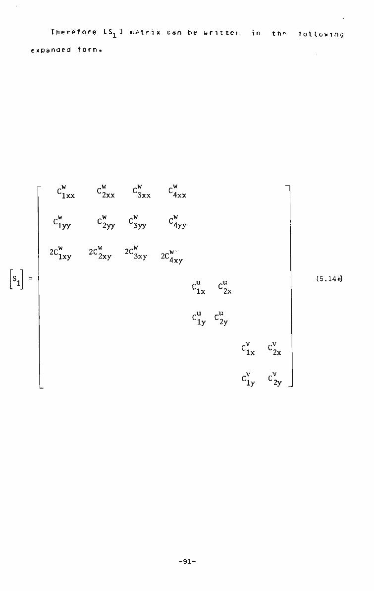
Therefore LS- 3 matrix can be written in the following
expanded torm•
Jlxx
,w 'iyy
2C w lxy
J2xx
,w
,w '3xx
,w '2yy 3yy
,w "4xx
J4yy
2C2xy 2C3xy 2CWxy
CU CU
4 x L2x
ly 2y
'lx
„v
1
'2x
'ly 2y
(5.14b)
-91-

5.4.4. Geometric matrix LK• »]3
The geometric n o n l i n e a r stiffness matrix can be written from
Eqn. 3.54, as follows,
W ' | Ls2?[*2} [<g « ' a.
(5.15)
The displacement and the shape functions used for the
linear matrix are the same in this case. The ^o ^ matrix
tor a single harmonic may be written in the following
part i t ioned form.
[Gcw]
[",] - [GCU]
[GCV]
(5.16)
-92-

The explicit form of LGC 3, CGC 3 matrices may be obtained
in a similar manner as the [EC 3,[EC 3 matrices in Eqns.
5.13-14 are giver as follows.
3C w
[<*"] -3x
3C w (5.17)
3y £ = 1,4
fac"
[GCU]=[ECU] . 3x
3C u (5.18)
3y £ = 1,2
[GCV] = [ECV]. - dx
3CV (5.19)
3y £ = 1,2
-93-

Therefore the £ s - 3 matrix can be cast in the following
ndedtorm,
"iy
J2x
J2y
J3x
,w
'4x
.w '3y 4y
'lx
u :iy
-, u ~2x
u C2y
'iy
1
c v c v
4x L2x
'2y
(5.20)
(6 x 8m}
•- ~_w 3c 3C w 3C w 3c w
3x 3x 3x 3x
3C .w 3C ,w dc .w 3C .w
3y 3y 3y 3y 3C u 3C u
3x
3c u
>x
9C u (5.20a)
3y 3y 3C v 3c;
3x 3x
3C, 3c!
L
3y 3y
-94-

8c» ac" zc] The .l...nt. _ , £. ...etc may be written as
^w a. v ulx' lx lx
where subscript x stands tor d i f f e r e n t i a t i o n
3C w ,w with respect to xt s i m i l a r l y — — is written as C l y a n o
3y
so on.
The coett i ci ent s , C^x, C^ x e t c . in LSI 3 mat M A are
independent functions of x and y. Therefore these functions
are separable in x and y. In the y direction the function
is analytic and harmonic dependent. For each set of
harmcnic(m) there is a corresponding set ot c^x, C™y
...etc. Therefore the s i z e ( c o l u m n w i s e ) ot the matrices LECJ
and [GC3 in Eqn. 5.11 and 5.16,20 will dramatically expand
with the number of harmoni c s (in) . For example the number ot
columns in the CS2] matrix is 8m. The value of m assumed in
Eqns. 5.11 and 5.20 equals unity.
Furthermore, the matrix [r<23 (Eqn. 3.4g>) is dependent
on the deflected shape of a structure. Therefore the
geometric matrix LK.^3 is also a function ot deflected
shape. This is unlike matrix LK13 whose elements are
constant and are dependent only on the elastic and geometric
properties of the structure. The detailed expressions of
the elpments ot LK^J ano IS23 matrices can be obtained ty
substituting the appropriate displacement functions (Eqns.
5.3 and 5.6-7) which is internally handled by the computer,
and will not be presented here.
-95-

5.4.5. Simulation ot initial imperfections
The term **w^' refers to the maximum initial out- ot-
plane deflections, a plate structure may possess. In the
present formulation the initial imperfections arc assumed to
contorn to the boundary conditions ot the plate. A typical
expression ot such a function tor a simply supported
platelfig. 5.2) is given as follows,
- „ . TTX . TTy w = w Sin — Sxn —*-o c B A
(5.21)
At the strip level the initial imperfection(w-) is
d e t i n e d b y
w = i w o \ c
Sin i[y_ (5.21a)
The procedure of der iviny {. w . > vector will be aisrussed later c
in Sec. 6.2.3. This procedure can also be used in the
large deflection problems in fixed plates having initial
imperfections. Equations tor the initial deflected shape
can be represented in two different ways, as
given below.
In the first case,
w = o
w Sin "!£ 15.22)
Thi_ it re+erred to as TYY type imperfection.
In the secono case,
w = {w ) S i n ^ - Sinh ^ - a [Cos - -
MX Cosh ^ 1 a J
a = Sin y - Sinh y_ Cos y Cosh y
(5.23) (5.24)
-96-

wnere
y = 4.7300
This is referred to as YKC type inperfection.
Although both ot these functions satisfy an identical
boundary conditions ot a fixed t late, but the response ot
the structure can be ditterert. The effect on the
loaa/detlection curve due to use of two types ot initial
displacement functions in clamped plates and the si r*, t y
supported plate cases, have been aiscussed in Sec. B.3.2.
5.5. Discussion
The detailed steps tor the evaluation of the non-linear
stiitness matrix ot a simply supported strip with restricted
inplane movement at the supports are provided. The explicit
expresssions for the elements ot the stiffness matrices are
avoided as far as possiole.
A *cherre n designee to accommoaate each ot the sters
described above as a separate subroutine (where possible) in
the computer programs. This procedure eliminates the chances
or leaking errors in the source code ot the program. The
stiffness matrices for other types ot strips s u c r as fixed
or free, having free or restricted in-plane movements can be
worked out by following the same procedure using appropriate
displacement functions(27 ). It may be mentioned here that
tor the folded plate and box type structures, the inplane
movements (u and v) along the longitudinal direction ot the
-97-
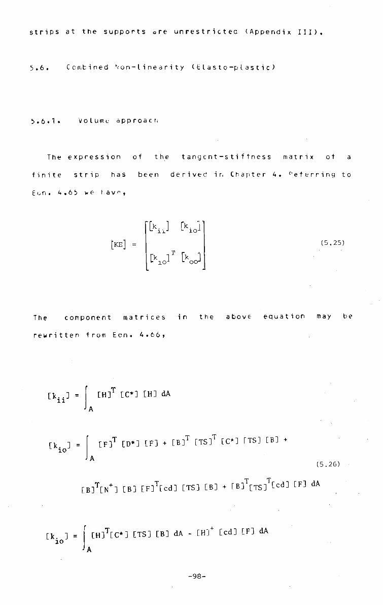
strips at the supports are unrestrictec (Appendix III).
5.6. Combined Non-linearity (Elasto-plastic)
5.6.1. Volume approach
The expression of the tangent-stiffness matrix ot a
finite strip has been derived in Chapter 4. deferring to
Eon. 4.65 we hav<-,
[KE] - (5.25)
The component matrices in the above equation may be
rewritten from Ecn. 4.66,
[kii] = CH]T [C*] [H] dA
[kio] = [F]T [D*] [F] + CB]T [TS]T [C*3 CTS] [B] •
A (5.26)
T Tr [B]T[N+] [B] [F]T[cd] CTS] [B] • [B] [TS] Led] [F] dA
[kio] = f [H]T[C*] CTS] [B] dA - [H]+ [cd] [F] dA
•A
-98-

The m a t r i c e s IC 3, Lu ) and LcaJ are general expresssions
tor elasto-plastic modular matrices in the area(Eqn. Ai.23)
/or in the volume approaches(Eon.4.^b ) The inaividual strain
matrices L8J,LF3, LH3 are obtainea ty pert orbing appropriate
derivatives required by Eqns.A.60-62. The same has been
presented in Section 4.5 and will not be repeated here. The
detailtd expressions ot LTS3 aro LN+3 matrices re^uireo by
Eqn. 5.27, have been provided in Eqns. 4.4b,52.
The modular matrices([C 3,CD 3 and [ c d 3 ) useu in Eqn.
5.27 require evaluation of matrix LE* (^z)] (Eon. 4.<i5).
When ire section ib elastic Lt*(Pz)3 is equal to LtJ. Trie
elements ot matrix [EJ, are constants, and they relate to
the elastic and geometric properties ot the finite strips
as gi ven be low ,
W - 1 - V
1 V
V 1
i+v 2 J
(5.27)
In ihe eI astop I astic s i t u a t i o n the modular matrix,
CE*(a_) 3 is a function ot current stress level (n ) at a
depth 2 of the plate. The vector {a } is defined by the
following equation.
N I [E (a )]{Ae }. i=1\r * t !
(5.28)
-99-

N equals the total number.of load increments. and
{0} can be expressed as,
{0} = z
X
xy
The e lements av a.„ x y
and
stresses at any level z(Fig
xy
(5.29)
in ,£ 0"} represent 2
3.3) These stresses can be
oad evaluated from strains .{Ae.}}, for individual I'
increment(i) and summed to give the current value of
stresses (Eqn. 5.3 0). Following Eqn. 4.22 , trie total
incremental strain {Ae*-} at any level z can be rewritten
as,
{Aet}z = {Aet} + z UX>} (5.30)
The incremental strain vectors (Ae } and {Ax} c a n b e
evaluated for any point over a strip by appropriately
difterentiating the displacement function and substituting
the incremental nodal line displacements.
The expression for LE*faJ 3 is obtainable from Eqns. z
4.25,A1.23 and using appropriate plastic potential function
*f ' (Eun'.A .16 or Fqn.4.53) depending on aoopteo aopr oac h ( a rea
or vo lume)•
5.6.2. Area approach
It has been mentioned earlier that the matrix
representations of the element stiffnesses and ot the
internal load vector in the case ot the area approach are
similar to the volume approach. In the area approach
LC* J, ID* j ,Lca*3 (Fqn. A1.23) and also <.«>,1NJ and IN41! (Eqn.
-100-
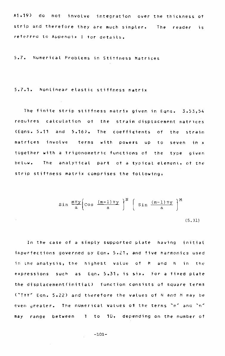
A1.19) do not involve integration over the thickness of
strip and therefore they are much simpler. The reader is
referred to Appendix I tor details.
5.7. Numerical Problems in Stiffness Matri ces
5.7.1. Nonlinear elastic stiffness matrix
The finite strip stiffness matrix given in Eqns. 3.53,54
requires calculation ot the strain displacement matrices
(Eqns. 5.11 and 5.16). The cdefficients of the strain
matrices involve terms with powers up to seven in x
together with a trigonometric functions of the type given
below. The analytical part ot a typical element, ot the
strip stiffness matrix comprises the following,
ntTry Sin JL
a
Cos (m-1) Try N t
Sin (m-1) Try ^ M
(5.31)
In the case of a simply supported plate having initial
imperfections governed oy Eqn. 5.21, and five harmonics used
in the analysis, the highest value ot M and N in the
expressions such as Eqn. 5.31, is six. For a fixed plate
the disp lacement (initia I) function consists of square terms
CTYY' Eqn. 5.22) and therefore the values of N and M may be
even greater. The numerical values ot the terms **m" anu "n'
may range between 1 to 10, depending on the number of
-101-

harmonics c o n s i d e r e d . However in most ot the numerical
problems solved in this research, the maximum value of m and
n considered is 5 and has been found to be adequate (Sec.
8.3).
The geometric non-linear analysis, the stiffness
matrixlEqn. 5.15) comprises, of the LKi3(£qn. 5.14b) and
LK23(Enn. 5..20 ) matrices whose elements are constant or
functions of total strains and slopes ot a section
respectively. As a result, only the integration over the
area is to be performed.
5.7.2. Elasto-plastic stiffness matrix
The numerical problems related to the elasto-plastic
stiffness matrix by the volume approach will be discussed.
In the e I as top lastic analysis only the parts of the strip
I a y e r * ( F i g . 6.3) will be plastic and, therefore the
formulation strictly requires separate integrations over the
elastic and plastic zones. Again a separate integration has
to be carried cut over the depth of the plate sectionCEqn.
4.30). This in turn presents the difficult problem ot
tracing, within the segmentlFig. 6.1) ot a strip, the
boundaries of the elastic plastic interfaces within a
domain. The problem has been avoided here by assuming(33)
that the tangent modulusLE*fa) } (Eqn. 4.25) varies zJ
continuously through the plate. This assumption is
reasonable if sufficient number of layers have been used.
In the present analysis only six layers have been retained.
The details ot the integration procedure has been discussed
-102-
in Section 6.5. Most of the terms in the element stiffness
matrix (Eqns. 5.26) is highly complex due to the presence of
these complicated expressions such as £E*fa) 1 and
LC*3,LD*3,Lcd3 etc. also due to the high order (up to 13)
polynomial terms in x.
The tangential modular matrices, LC*3v,CD*3v and Ccd3v
(Eqn. 4.30) in the volume theory are formed by integrating
over the thickness of the plate. These matrices are
functions of the modular matrix CE*(a)^] (Eqn. 4.25) which
is in turn a function of the totat stress (ay (Fqn. 5.2S).
Consequently the total stress vector must be stored in each
Gaussian integration point at each of the slices into which
the plate is divided(Fig. 6.3). The details of this
integration procedure are provided in the next Section.
In the area approach LC*3.LD*3 and Lcd3 are functions A A A
of stresses <.N> and if\> at a section of the plate. These
vectors are evaluated from the curvature consideration and
integration over the thickness is not required.
5.7.3. Discussion
The polynomial functions in the stiffness matrix are
amenable to integration by Gaussian quadrature provided that
a sufficient number ot Gauss points are useo. Osing this
apprdach a polynomial ot degree I2n-1) may be exactly
integrated with ~n' Gauss points. In order to integrate the
analytical function part of the stiffness matrix the
straightforward application ot Gaussian quadrature will in
general not lead to an accurate solution. A systematic
-103-

parametric method has been adopted to d e t e r m i n e the optimum
numt.er ot Gauss points to integrate a combined analytical
and polynomial function which forms the elements ot the
non-linear finite strip stiffness matrixlEqns.
4.65,5.10,15). The details of the parametric study is
provided in Sec. 6.3.
In the x-y plane the variation of strain (hence ot
stress) is of a high degree and for exact integration the
number of Gauss points required will be very high (more than
13), rendering the computation very expensive.
CrisfieId(33) integrated the polynomial function ot similar
type, using a small number of Gauss pointslonly 2), chosen
arbitrarily without any check for accuracy. It will be
noted in the next section that the indiscriminate use ot
such lower order integration tor higher oroer function will
not in general lead to accurate results. However the
procedure, suggested in this studylbec 6.2.2) avdids this
error and this problem will be re-examined in Chapter 6.
-104-
6.
CHAPTER 6
NOMERICAL INTEGRATION
6.1 . Genera I
A description of the shape functions used to represent
the displacement tietas ot the finite strip is given in
Appendix III. In order to evaluate elements of the
stiffness matrices which are derived from such displacement
functions, integration ot the expressions formed by higher
order polynomial and trigonometric functions is required.
The degree ot the polynomial part is as high as 13 and the
analytic part also contains higher power of sines or cosine
functions(Eqn• 5.31). However in most of the problems dealt
with in this thesis, only 5 harmonics have been retained in
the finite strip displacement function. Therefore, the
stiffness co-efficients for up to 5 harmonics will be
discussed here. A concept called 'segmented finite strip'
has been introduced in this study in order to evaluate the
coefficients of the finite strip stiffness matrix. A
special purpose numerical integrat ion (gaussian type)
technique has veen developed. A results of a parametric
stuuy(Tabs. 6.1-3) proves the validity ot the adopted
integration procedure.
The degree ot the polynomial function and the nature and
complexity of the analytical part depend on the order ot the
-105-

strip (third or fifth e t c . , 74) as well as the boundary
conditions ( e.g. simply s u p p o r t e d or f i x e d ) ot the
structure under c o n s i d e r a t i o n . In the present research the
large d e f l e c t i o n elastic and e l a s t o - p l a s t i c stiffness
matrices tor the third o r d e r b e n d i n g strip are f o r m u l a t e d .
The stiffness m a t r i c e s ot the higher order strips may be
obtained in a similar w a y . The finite strip developed,
enables free or restricted inplane m o v e m e n t s at supports to
be included in an a n a l y s i s . The bending boundary conditions
may either be simply s u p p o r t e d or fixed at the two opposite
ends of the s t r i p . The n u m e r i c a l i n t e g r a t i o n related to the
non-linear elastic stiffness m a t r i x ( g e o m e t r i c part o n l y ) and
the volume i n t e g r a t i o n in p r o c e d u r e adopted to obtain the
elasto-plastic s t i f f n e s s matrix are disccussed in the
following s e c t i o n .
6.2. Geometrically Nonlinear Case
The numerical integration method employed to eva
coefficients of the g e o m e t r i c matrix I K ^ will be
The other f o r m u l a t i o n s such as LK 3 in elastic anal
In e l a s t o - p l a s t i c analysis are also based on
finite strip d i s p l a c e m e n t f u n c t i o n s , and identical
has been a d o p t e d .
The s t i f f n e s s matrix for the g e o m e t r i c a l l y
analysis is r e w r i t t e n from E q n . 3.55, as f o l l o w s :
[Kinc] - c>g • i*Bli
where LK J and LKn J are referred to as the linear and I nil
luate the
discussed
ysis LK e3
the same
procedure
non I i near
(6.1)
-106-

geometric stiffness matrices respectively. As discussed
before(Section 5.6) the elements of IK: 1 contain terms in nil
'x' ot order 13 and in *y" a chain of higher order
analytical functions ano are difficult to integrate
explicitly. A new numerical integration technique is
proposed for the integration of the finite strip stiffness
matrices. The detail steps involved to obtain the elements
ot nonlinear stiffness matrixiLK (i,])3 tor a simply nil
supported strip is presented.
6.2.1. Displacement tunctions(S.S. Strip)
The bending displacement field of a simply supported
strip(Fig. 3.1) can be written in the following from,
w = C. w. + C„ 6. + C w. + C„ 9. (6.2)
1 l 2 l 3 j 4 j where,
.w
and ,
C - ?= (1 - 3x + 2x ) Y
(x - 2xx + x x) Y
) Y _2 _3
(3x- 2x
.» ,-2 -C, = (x - xx
7 = x/t
b = breadth ot the strip
a = length of the strip
m - number of harmonics
) Y
w n\ w m
w m
w m
(6.2a)
yW m
= 9 in vmy y ^ = m-TT in
'.m = 1,2, 3 (6-2b)
According to Eqns. 5.8-y the inplane displacement functions
-107-

are ,
where
and
u u u = C. u. + C_ u.
1 i 2 j v v v = C. v. + C _ v .
1 l 2 j C? = (1-x) YU
1 m C* - (x , YU
2 m d-x) Y
, = (x ) Y 2 m
m
v
= Sin
Y = Cos m v Y
a
m 9 i n M±DL
- a
(u restrained)
(v unrestrained)
(v restrained)
(6.3)
(6.3a)
(6.3b)
6.2.2. Geometric stiffness matrix - LKnJl3
The geometric stiffness matrixLK.v J derived in Sec. 3.6.2 n£
(Eqn. 3.54) is rewritten hereunder,
[*nJ [SJ[KJLSJ ^ (6.4)
The procedure of obtaining the coefficient ot LS^3 (Eqn.
5.2U) have been described in Sec. 5.4.4. The elements of
matrix CK 3(Eqn. 3.49) are function of deflected shape of 2
the structure anc of the initial displacementslit present).
The explicit form of the elements ot LK2 3 is very lengthy
and will not be presented. The evaluation ot each component
matrices in Eqns.(6.4) is internally handled by the
-108-

computer •
6.2.3. Initial Deflection
In the present formulation the initial out-ot-plane
imperfection ot the structure lplate) is assumed to conform
with the respective boundary conditions(Fig. S.1). For the
simply supported plate the initial deformation takes the
torm(Fig. 5.2),
~ . Try „ . TTX
w = w Sin —*- Sin —— o c a b
(6.5)
The above equation is expressed in the form ot finite strip
displacement function as,
w = [c* C* C* cT] Sin 2Z { w } (6.6) o *• 1 2 3 4J a L cJ
where
rw
f»J -Cl
e. Cl
w 93
0 .
(6.7)
Cl Cl
etc. are evaluateo by
substituting appropriate co-ordinates to the equation tor
wo(Eqn. 6.5). This approximation of simulating a sinusoidal
function by a polynomial function will not cause significant
error it the imperfections in the plate is defined by a halt
-109-

sine wave and the plate is divided into a sufficient number
of strips (say 5 over symmtrical half of a plate).
6.2.4. Numerical evaluation ot element jKn^(i,j)
The elements ot LSnilJ matrix ot sizelomx&m), can be
written explicitly by the substitution ot C'S.23 and L K23
matrices in Eqn. 6.4. The explicit form of some of the
typical elements ot L.Kn^3 matrix is presented hereunder.
K f (1,1) = C* [c™ K (1,1) + C* K,(l,2) n* lx L lx 2 ly 2
K«f.(2'1} - cTv KvS.^ 1' 1) + c2vK^i»2) 'lx L 2x 2 2y 2
KiP*» -c" KVK,(1,1) +C%(1,2) nil lx L 3x 2 3y 2
Ki^'U - CL KLv 1 ^ + C L K , ( 1 ' 2 ) lx L 4x 2 4y 2
Kp(5,l) - C * [C?K(1,3) + c" K (1,4) nil lx L lx 2 2x 2
K nil (6,1) = df [c" K.<1,3> + S K_(l,4)
'lx L ly 2 2y 2
K„,(7.D « C* [< K.(l,5) + C^ K2(l,6) nil ly 2
Knil(8'1} = CIx C CL K 2 ( 1 ' 5 ) + C2yK2(1'6 )
K nil (2,2) = C* [cl K_(1,D + < K (1,2)
2x L 2x 2 2y 2
+ C I y [ClxK2(1'2) ^ C I y K 2 ( 2 ' 2 )
+ CIy CC2xK2a'2 ) + C 2 y K 2 ( 2 ' 2 )
+ Cly ^C3xK2(1'2) + C3yK2(2'2)
+ CIy t!xK2(1'2) +CIyK2(2'2)
+ Cly £ClxK2(2'3) + C2xK2(2'4)
+ CIy tClyK (2'3) + C2yK2(2'4)
+ CIy &IxK2(2'5) + CIyK2(2'6)
+ Cly &LK2(2'5) + C2yK2(2'6)
+ C2y &LK2(1'2) + C2yK2(2'2)
(6.8)
In order to evaluate the elements ot the geometric
stiffness matrix '-*no^» each ot the above expressions need
to be doubly integrated (numerically) in the following
manner.
-110-
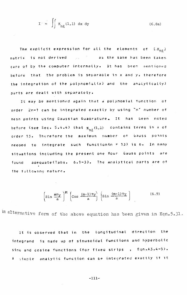
I • = K (1,1) dx dy n£
(6.8a)
The explicit e x p r e s s i o n for all the elements of £.1^3
matrix is not derived ... as the same has been taken
care of by the computer internally. It has been mentioned
before that the problem is separable in x and y, therefore
the integration of the polynomia I(x) and the analytically)
parts are dealt with separately.
It may be mentioned again that a polynomial function ot
order 2n-1 can be integrated exactly by using "n" number of
mesh points using Gaussian Quadrature, It has been noted
before (see Sec. 5.4.4) that K„C1,1) contains terms in x of ni6
order 13. Therefore the maximum number ot Gauss points
needed to integrate such tunctionln = 13) is 6. In many
situations including the present one tour Gauss points are
found adequate(Tabs. 6.1-3). The analytical parts are of
the following nature.
Sin IMT M
Cos (m-1) Try (m-1) try
Sin •*-(6.9)
n a l t e r native form of the above equation has "been given in Eqn.5.31.
It is observed that in the longitudinal direction the
integrand is made up of sinusoidal functions and hyperbolic
sine and cosine functions (for fixed strips , Eqn.A3.4-5).
A simple analytic function can be integrated exactly it it
-111-

is possible to predict its o s c i l l a t o r y b e h a v i o u r . H o w e v e r a
highly oscillatory function can not be handlea under any
numerical integration technique as indicated oy Price (99).
Filon(47) has provided a method for integrating finite
tourier integrals. No work so far has been reported which
deals with a complicatated integrand(Eqn. 6.9) which is
involved in the present finite strife stiffness formulation.
The problem of numerical integration of expressions
composed of higher order polynomial and rather complicated
analytic functions is investigated in the following
sec ti ons .
6.2.5. Concept of "Segmented Strip"
The term "Segmented Strip" used herein means that a
finite strip is subdivided into a number of segments in the
longitudinal and as necessary also in the transverse
di rection(Fig. 6.1). In order to evaluate the elements ot
the stiffness matrix of a finite strip, Gaussian integration
of the complicated analytic and polynomial expressions are
performed over individual segments and summed.
This gives the finite strip procedure aaded tlexibilty
in simulating a physical structure without destroying its
existing merits. Some of the extra advantages gained are as
tollows.
(i) The geometric, elastic or elasto-plastic properties ot
a segment of a finite strip can be varied i.e. each
segment may be deemed as a finite element in terms of
-112-

representing the physical n a t u r e ot a p r o b l e m ( F i g .
6.1).
(ii) Due to the strip sub-division, the number of Gauss
points available to integrate the stitfhess
expressions, is much higher than considering the strip
as a whole. In other words this procedure replaces a
higher order Gauss quadrature over a strip by a lower
order Gauss quadrature on the segments. Thus it
retains the global function representation ot the
finite strip method but achieves the local integration
flexibility. This makes the present procedure
comparable to a finite element method.
It may be mentioned here, this lower order
Gaussian Quadrature is applicable to the finite strip
stiffness function irrespective of the nature of
analysis (elastic or elastoplastic). The reliability
ot this technique has been established through
parametric studies (Tabs. 6.1-3) using number
segments(NICR) and Gauss points in the x(NGX) and
y(NGY) directions as variables.
It is possible to analyse a strip whose elastic
properties can vary within a segement even when an
elastic analysis (linear or nonlinear) is performed.
In the elastoplastic situation all gauss points have
different modular matrices(Eqn. 4.3/) and integration
of the stiffness tunction(Eqn 4.66) is performed over
the segments and summed. The same procedure may be
used in the tormer(elastic) analysis.
The segmentation procedure allows the use ot more
-113-

Gauss points where increased accuracy is needed. The
available library routine(GAOSS ) on ONIVAC Computerlat
Wollongong University), can cope with only 16 Gauss
points. In this study a maximum of 5 Gauss points
along any particular directionCx or y) has been found
to be adequate. This proved to be the case, provided
that the chosen number ot segments are adequate the
present procedure can be recommended as an alternative
to a finite element procedure. Although the
displacement field representation by these two methods
(viz. finite strip and finite element) are different.
At this stage the segmented strip method can be
useful for the elastic analysis of non-prismatic
structures having variable geometric properties within
a segment*
It may also be noted that the total number of
Gauss points neeaed to integrate a finite strip
stiffness matrix is usually less than that required by
a corresponding finite element analysis. A simple
calculation will justify this point. Normally the
total area of a strip is represented by eight finite
elements(33) i.e NICR = c in Fig. 6.1. It this global
representation is adequate, then by using 5 6auss
points in x and in y, 200(8x5x5) Gauss points will be
necessary to evaluate the stiffness ot the portion of
a plate. This comparison is based on the assumption
that the degree ot the polynomial tunctionlin x and y)
representing an element of a finite element stiffness
matrix is 13. Whereas it will be noted that only 90
-114-

Gauss points are aoequate tor a finite strip stiffness
matrix(Tabs• 6.1-3).
Therefore the suggested numerical integration scheme when
used in conjunction with the finite strip methoo, retains
all the advantages of a conventional finite strip procedure
and is also expected to be computationally less expensive
than a comparable finite element ana lysis(33). However the
advantage gained by this modest requirement ot g?uss points
may be offset if the length ot the stiffness expressions
increases as result of higherlNHARM <5) number ot harmonics
requirements. Parametric studies may be undertaken in
order to compare the efficiencies ot the finite strip and
finite element methods in solving nonlinear problems. This
stuuy is beyond the scope of the present research.
It may also be mentioned here that the use of higher
numoer ot Gauss points may not necessarily produce accurate
results unless the correct number ot subdivisions has been
usea in the longitudinal direction(Tabs. 6.1-3).
In oroer to determine the optimum number of sub-division
and Gauss ooints in the x and y direction the following
parametric study has been undertaken.
6.3. Parametric Study
The purpose of the parametric study is to obtain the
optimum combination of the following variables (Fig. 6.1) to
accurately integrate the finite strip stiffness matrices.
The variables are:
-115-

o Number ot segments in the strip (NICR)
o Number ot Gauss points in the X direction (NGX)
o Number of Gauss points in the Y d i r e c t i o n (NGY)
It should be mentioned here that the problem is
separable in x and y, and therefore the number ot Gauss
points required in the two d i r e c t i o n s l x and y) are dictated
by the nature of the individual f u n c t i o n s .
The numerical values ot NICR,NGX and NGY are
systematically varied tor a typical g e o m e t r i c a l l y non-linear
problem. The case of a simply supported strip (Fig. 6.1) is
di scussed in detai I.
Hlate ^ABCD" in Fig. 6.1a is restrained against in-plane
movements and subjected to uniformly distributed load. Only
one half ot the plate is considered due to s y m m e t r y . The
incremental loading is used. The detailed d i m e n s i o n s ,
elastic and geometric p r o p e r t i e s of the plate are shown in
Fig. 6.1.
This study is concentrated on the numerical values of
certain elements of a strip stiffness matrix at some stage
of loading when the plate is assumed to behave n o n - l i n e a r l y .
In this i n v e s t i g a t i o n , strip 2(Fig. 6.1a) is c o n s i d e r e d .
Two types of initial o u t - o t - p l a n e d e f o r m a t i o n cases are
dealt with; w Jh - 0. and 1. The total number of harmonics c
considereo is f i v e . Since the problem is geometrically
non-linear, three bending d i s p l a c e m e n t s (w,9 and 6 ) and 9 r x y
two inplane d i s p l a c e m e n t s (u,v) have been considered at each
nodal line. A maximum of five h a r m o n i c s has been retained
in the d i s p l a c e m e n t f u n c t i o n . Therefore the size of the
-116-

element stiffness matrix will be 4 0 x 4 0 (Fig. 6 . 2 ) .
Since we are dealing with the nonlinear part of the
stiffness matrix we need to consider two consecutive stages
ot load increment say N-1 and N (N >1). in this study the
stiffness matrix for strip 2 tor load increment stage 3 is
evaluated tor various combination of NICR,NGX and NGY.
Therefore the displacement vector for each nodal line from
load stage 2 is stored tor SUPStitution, in order to
calculate the elements of [K'. ] for the strip.
The numerical values of typical elements of the stiffness
matrix(Eqn. 3.54) are provided in Tables 6.1 to 6.3. The
subscripts i and ] in Sij represents the element at the ith
row and jth column ot the one of the LS3 8xb matrices
corresponding to a set of harmonic 1ST and JST. Fig 6.2
shows a 4ux4C matrix CA3 whose submatrices are 1S3 and of
size- 6 x a •
6.4. Discussion
It may be observed from Tables 6.1-3 that the best
combination of the parameters NICR,NGX and NGY in order to
obtain convergence, are 3,5 and 6 respectively. Strictly at
least 7(n) Gauss points are needed to integrate a polynomial
function of degree 13(2n-1). Crisfield, in his finite
element analysis<33), assumed that only d Gauss points are
needed to integrate polynomial functions ot same order, 13
without any justification. It may also be mentioned here
that Crisfield<33) used eight elements over a strip area
which is idealised by only three segments in the present
-117-
method.
The convergence of the analytical part ot the stiffness
expression(Eqn. 6.8a) depends primarily on the chosen number
ot subdivisions and once it has been fixed it is rather a
simple task to determine the value NGY in each subdivision
to obtain a sufficiently accurate integration. It should be
emphasised that the mere use of a high number of Gauss
points (NGY) for the trigonometric functions may not
necessarily lead to the correct solution it the number ot
segments(NICR) is not chosen judiciously. For example the '1
combinations 5,4,5 uses the more Gauss points than reouired
by 3,5,6 (Tabs. 6.2-3) but leads to inaccurate integration.
In order to trace the influence of various parameters on the
results of integration of this kind, it is suggested that
the size of the segments should be kept uniform unless a
special situationsuch as prismatic section arises. The
procedure (integration) has also been extended to cover the
elasto-plastic case, although no separate parametric study
is performed. The suggested values ot NICR,NGX and NGY for
integrating the finite strip stiffness matrices (both in
elastic and elastoplastic cases) are 3,5,6 respectively.
Perhaps an alternative numerical procedure such as
Simpson's rule could be used to integrate the trigonometric
functions. This rule uses an even spacing ot the integration
points and is likely to produce accurate results. This is
more apparent from the tact that the adopted(modifled)
Gaussian integration technique divides the integration
domain in equal number ot segments and then operates on a
lower order Gaussian rule which resembles the Simpson's
-118-

rule.
In some cases such as S(1,1), etc. the numerical
integration results have converged very quickly and
theylresults) do not change appreciably with the increase ot
the magnitude of the governing variabtes. It has been noted
that the expressions (analytic part) for such coefficients
(e.g. S11, etc) are well behavea and only in these cases
lower value of the parameters may be recommended(Tab.
6.2-3). However this is not always the case and chances
should not be taken. Since it is an extremely difficult
task to trace the optimum combination for each individual
element, it is suggested that the limiting values of the
parameters should be determined by the pattern showed by
Tab*. 6.2-4. Although the procedure may involve some extra
computer cost but the convergence ot the result is assured
and also the procedure requires relatively less
familiarity of the user with the computer program, and with
the complicated stiffness functions. Nevertheless it has
been established earlier in this section that the optimum
valuesd.e. NICR= 3,NGX = 5 and NGY = 6) ot the variables
require tot less Gauss points than used in a comparable
finite element analysis.
The suggested procedure to integrate a combined analytic
and polynomial function, involved in the finite strip
stiffness equations can be employed in other cases as well.
More often in \'£ ,. practical numerical problems, it is very
difficult to perform manually an integration explicitly
because of its complication, and often it is very difficult
to arrive at a decision which approximate method to be
-119-

followed in order to obtain an accurate solution.
Nevertheless the present method demonstrates a simplistic
approach to such problem.
The elements ot the elastoplastic stiffness matrix is /ibe
also derived from exactly same displacement function, as in
the geometrically nonliner elastic case. The expressions of
the elasto-plastic stiffness rnatrixlnot presented) a*« more
lengthy due to incorporation ot stress terms in the
derivationlEqns. 4.52-54). However the nature ot the
stiffness functions, both in the elastic and elastoplastic
analyses is the same, therefore the results of the
parametric study in the elastic large deflection case a-re
also used in the elastoplastic case without further
investigation. The suggested integration procedure
(segmentation) is approximate but accurate. For the details
on other integration methods (approximate) used in the
finite element analysis reader is referred to a text by
Strang and Fi x(11fca) .
6.5. Volume Integration
In the elasto-plastic analysis only the parts ot the
Plate domain will be plastic, therefore the formulation of
the stiffness matrix strictly requires separate integration
over the elastic and plastic volumes.
The tangential modular matrices, LC*3^,LD*3V and LccJy
(Eqn. 4.30) required in the stiffness equations, are formed
by means ot integration over the depth of the plate* These
matrices are functions of the modular matrix tE*(C£).3 (Eqn.
-120-

4.25) which is in turn a function ot the total stress
r?z (Eqn.5 .29). Consequently the total stress vector must be
stored at each Gaussian integration level.
The integration over the de^th ot the structure is
carried out by assuming that the finite strip is composed ot
a number of finite layers (Fig. 6.3). In order to evaluate
the tangential modular matrices (Eqn. 4.30) tor the full
section, integration is pertormea over each layer and the
results summed. The integration is performed explicitly by
assuming that the variation of E* (az) (Eqn. 4.25) is linear
over the layers(Fig. 6.3). The accuracy of such an
integration increases with art increase in the number ot
layers. Six layers were found to be adequate, as compared to
ten required if the numerical integration was performed by
Simpson's Rule (Crisfield 1973). However no conclusion can
be made at this stage regarding the choice ot the optimum
number of layers unless a larger parametric study is
undertaken. It may be mentionea that if the assumed
variation of JE* (az)] is close to linear, the adopted
explicit integration procedure should provide by tar the
most accurate solution. When a section ot the structure is
completely elastic the stresses are stored and monitored
only at two Gauss stations at the upper-most and lower-most
layers (top ot layer 1 ano bottom ot layer 6 in Fig. 6.3).
The integration over the depth is by-passed tor such
sections since the modular matrices(Eqn• 5.27) are known
explicit ty.
It shoulc be noted that in the area approach IC 3ALD3A
and Lcd3amatrices are functions ot stress vectors tN> and
-121-

{IO over the whole section and t h e r e f o r e the integration
over the thickness is not requirec.
The elastic non-linear analysis uses the matrices
LKi3(Eqn. 3."48) and LK23(Eqn. 3.49 ) whose elements are
constant or functions ot the total strains and the slopes of
a section respectively. As a result, only the integration
over the area is to be performed.
6.6. Application to Non-prismatic Structures
The conventional finite strip method(25) and its
subsequent developments have rarely been used to investigate
structures which have variable cross-section in the
longitudinal direction. With the introduction of the
segmented finite strip concept, it is possible to analyse
non-prismatic structures in both the elastic and nonlinear
elastic and elasto-plastic ranges. Only an elastic beam
problem will be considered here to show the validity of the
procedure•
Cheung et a I(24) analysed a brioge structure having a
varying cross-section along the longitudinal direction and
supported by intermediate columns, using a tower oraer
finite strip procedure. The present finite strip method,
can only be used to investigate structures which are
supported at the end sections, theretore discussion will be
limited to the problems of a beam, simply supported at the
ends. Only linear elastic behaviour is assumed.
-122-
6.6.1* Simply s u p p o r t e d beam
A simply s u p p o r t e d oeam having v a r i a b l e moment of
inertia as shown in Fig. 6.4, is subjected to a uniformly
distributed load. The maximum detlections are compared
with the results given by beam theory in Table 6.4. The
correlation between the results are satisfactory. when the
value of alfa which is defined as the ratio of minimum and
maximum momenta ot inertia (Tab. o.4) ot the beam is small
the discrepancy of maximum deflection by the finite strip
method and beam theory teno to rise. Although the segments
of the finite strips have been chosen to suit the change in
geometry ot the beam there will be some error in the
simulation of actual beam due to discrete positioning of the
Gauss points. This error has been minimised by choosing
sufficient number of segments such that the extreme Gauss
points do not lie too tar from the section where the change
in the cross-section occurs. Perhaps the same difficulty
will be experienced in the finite element analysis ot a
non-prismatic structure. It may be mentioned here that the
object et this exercise is to show how a finite strip method
can incorporate the change in the elastic or geometric
properties causea either by the change in cross-section or
by an eguivalent change in the elastic properties due to the
elastoDlastic yielding ot a portion ot a strip. In the
elastoplastic situation the change in strip properties
between the two consecutive Gauss points may not necessarily
be very abrupt. It may be stated here that in the
elastoplastic analysis the stiffness matrix is evaluated by
-123-

considering the v a r i a t i o n of the e l a s t o p l a s t i c p r o p e r t i e s at
each Gauss point on the on each layer ot the finite strip.
The same technique can be tailoreo to suit the s<iall
deflection elastic analysis ot nonprismatic structures. In
the later case the elastic ano the cross-sectional
properties of a portion (segment) of the structure generally
remains constant. In this study no attempt has been made to
trace the spanwise variation elastoplastic properties ot a
strip when material has commenced to yield. However chances
must be taken in view of the results given in Tab. 6.4 for
the non-prismatic beam problems. Again as noted atove trie
discrepancy in the results may further be minimised by
choosing even'larger number of segments near the section
yhere the change in cross-section occurs.
-124-
CHAPTER 7
SOLOTION PROCEDORE
7.1 . Genera I
The principle of minimum total potential energy provides
the basis for the formulation of large deflection elastic
and elasto-plastic problems considereo in this research.
This leads to a set ot nonlinear equilibrium equations,
which can be solved by some special techniques such as
incremental, Iterative or Newton methods and mixed or step
iterative procedures. The complete discussion ot all those
procedures is beyond our scope. The basis of some ot the
above procedures as implemented in the solution ot the
finite strip stiffness equations, is given. A generalised
mathematical basis tor the incremental and iterative methods
is given by Oden (97). A brief review ot the fundamentals ot
such methods is also available in a text by Desai and
Abel(35) .
The non-linear equilibrium equation tor a sinole strip or
an element may be written as follows,
M(q} = {P) (7.1)
In structural mechanics problems, nonlinearity may occur in
the stiffness matrix due to large deflection in the
-125-
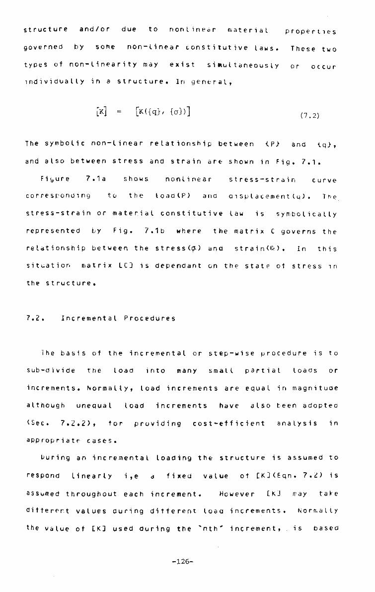
structure and/or due to n o n l i n e a r material
governed by some non-linear constitutive laws.
types of non-linearity may exist simultaneously
individually in a structure. In general,
[K] = [K({q>, {a})]
The symbolic non-linear relationship between tP> and iq>,
and also between stress and strain are shown in Fig. 7.1.
Figure 7.1a shows nonlinear stress-strain curve
corresponding to the toad(P) arid d i sp t acement (q) . The
stress-strain or material constitutive law is symbolically
represented by Fig. 7.1b where the matrix C governs the
relationship between the stress(<^) and strain(&). In this
situation matrix LC3 is dependant on the state ot stress in
the structure.
7.2. Incremental Procedures
The basis of the incremental or step-wise procedure is to
sub-divide the load into many small partial loads or
increments. Normally, load increments are equal in magnitude
although unequal load increments have also been adopteo
(Sec. 7.2.2), tor providing cost-efficient analysis in
appropriate cases.
During an incremental loading the structure is assumed to
respond linearly i,e a fixed value ot LK3(Eqn. 7.2) is
assumed throughout each increment. However tKJ way take
different values during different load increments. Normally
the value of £K3 used during the "nth* increment, is based
properties
These two
or occur
(7.2)
-126-

on the d i s p l a c e m e n t or stress c o n f i g u r a t i o n as the case may
be, of the structure at the end of the "(n-l)th' load step.
7.2.1. Constant load increment
In the constant load increment case the load step sizes
are constant for each increment and the adopted solution is
straight-forward. The matrix representation and the related
tlo* charts tor this procedure are provided in Sees. 7.4 and
7.5. The elasto-plastic analysis ot plates has been dealt
with by the constant load increment procedure.
7.2.2. Varying load increment
The purpose ot varying the load increments is to make
the solution program cost-efficient without sacrificing
accuracy. The load increment sizes will be controlled in
such a manner that the ratio of any two consecutive
increments is a constant designated by * r ' . This was first
proposed by Yang(144) who derived an expression relating
total incremental load and the initial increment oy studying
the load displacement curve and performing an error
analysis. The equation tor varying the toad increment is
given as :
Eh (7.3)
-127-

At any stage *n", total load *u' is gi ven by t
Q = / i n - l
c(1 - r ) (1 - r)
(7.4)
in which,
A = length of the structure
c = size ot initial increment
E = Modulus of elasticity
h = thickness ot the structure
r = ratio of two successive increments
or a geometric constant(r>1.)
n = step number, and
PA1*/Eh1* = non-dimens iona I iseo load
According to E q n s . . 7.3-4 each load increment is r
times the previous onelwhere r>1.). Therefore the load
increment at the "nth' step is specified by Eon. 7.3. The
rant,e ot the numerical values ot r is 1 to 1.3, ano the
value ot c, the initial increment ot load is the maximum
loau up to which the deflections are governed by the smalt
deflection theory i.e. wc/h<.3 (Eqn. 6.5).
In the class ot problems considered in the present
research, especially in plate structures there is a
relatively high change ot slope of the load/deflection curve
at the initial stage of loadingl see Figs. £.2-3,6-9,
13,16-19). Thi« rate ot change ot slope diminishes quite
appreciably at the higher loao level. Such behaviour
justifies the use of smaller load increments initially with
gradual increase at subsequent stages. Using this
procedure, there will be a substantial decrease in the
-128-

numDer ot load steps to reach any target load level when
compared with a constant increment strategy(Fig. 7.2a).
This charactaristic can also be observed in Eon. 7.4(where
r>1.). The numerical values ot *c' and V tor various
plate problems as recommended by Yang(143-44) have been
adopted in most cases. In some solutions a departure has
been made, and these are discussed in the next section.
The matrix representation ot the constant and varying
incremental procedures (Sec. 7.5) is the same excepting that
loaa vector at each step is higher than that in the latter
case. The varying load increment method has been applied in
the large deflection analysis ot plates and ot platea
structures•
7.3. Step Iteration
The purpose of combining an iterative procedure with
the incremental one so called step iteration is to check the
convergence of the results. Although the constant and
varying toad Incremental methods have been found to be
adequate to solve some nonlinear problems in certain class
ot structures, the merits ot a combined procedure can not ce
overlooked. A combined procedure has a control over the
accuracy ot the nonlinear analysis at any stage ot loading.
Also it gives an idea of the upper bound ot increment sizes
that can be used confidently in a purely incremental
analysis. It is obvious that the step iteration method is
more accurate than the incremental procedures but expensive.
The optimum load increment size which is able to replace the
-129-
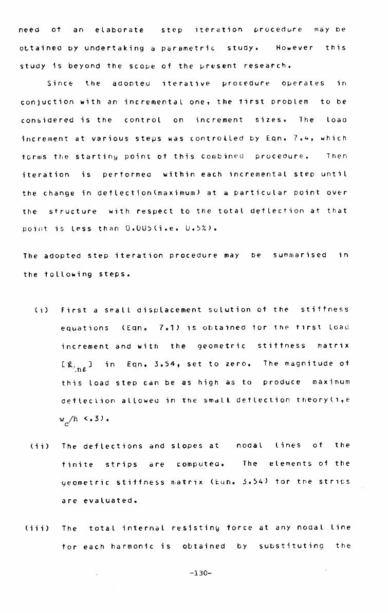
need ot an e l a b o r a t e step iteration procedure may be
obtained oy undertaking a parametric study. However this
study is beyond the scope of the present research.
Since the adopted iterative procedure operates in
conjuction with an incremental one, the first problem to be
considered is the control on increment sizes. The load
Increment at various steps was controlled by Eqn. 7.4, which
forms the startiny point ot this combined procedure. Then
iteration is performed within each incremental step until
the change in defleetiontmaximum) at a particular point over
the structure with respect to the total deflection at that
point is less than 0.005(1. e. 0.5%).
The adopted step iteration procedure may be summarised in
the following steps.
(i) First a small displacement solution of the stiffness
equations (Eqn. 7.1) is obtained tor the first load
increment and with the geometric stiffness matrix
it... 3 in Eqn. 3.54, set to zero. The magnitude of .ne
this load step can be as high as to produce maximum
deflection allowed in the small deflection t h e o r y (l , e
w /h <. 3 ) . c
(ii) The deflections and slopes at nodal lines ot the
finite strips are computed. The elements ot the
geometric stiffness matrix (Eqn. 3.54) tor the strips
are eva luated.
(iii) The total internal resisting force at any nodal line
for each harmonic is obtained by substituting the
-130-

stored displacement vector in the above step into the
linear and geometric stiffness eduations based on the
displacements from step (ii). The difference
between the resisting and applied forces in a
particular step represent a set ot unbalanced forces
tor a certain configuration of the structure.
(iv) Knowing the set ot unbalanced forces (step iii) on
the model due to the configuration in step (ii), the
incremental nodal displacements within a load step
(i) can be so Iveo .
(v) The incremental displacements in step (iv) are added
to the total displacements, and the updatea geometric
stittness matrix is evaluated.
(vi) Convergence Test:
Steps (ii) to (iv) will be repeated until the ratio
of displacements (incremental) in step (iv) and total
displacement, is less than some convergece limit e. .
In the large deflection nonlinear elastic problems
the the value e has been set at 0.005 for the section
where maximum deflection occurs.
(vii) The next load increment is applied and steps (ii) to
(vi) are repeated.
The graphical representation ot the step iteration
procedure and the incremental procedures are given in Fig.
7.2 and 7,5,
The step iteration procedure has been used in the large
-131-

deflection elastic analysis of perfect plates in order to
demonstrate the validity ot the finite strip method in
solving non-linear problems by incremental and iterative
methods•
7.4. Matrix Representations
r*.4.1. Constant load increment
The incremental solution of nonlinear stiffness equation
may be represented by the following equations.
*• Jn L J n v Jn K 'n-1 (7.5)
[ xnc Jn-1 M'CV] n-l
(7.6)
H •* 'n
[K .Dn = [0] for perfect structure.
^ [0] for imperfect structure,
is the increment in load vectors at nth load step,
jqf represents total displacement vector at any stage n, *• •'n
-132-
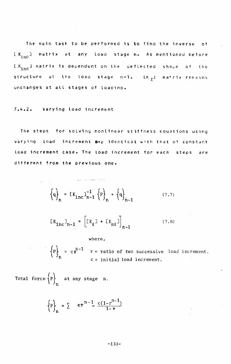
The main task to be performed is to find the inverse ot
tl. 3 matrix at any load stage n. As mentioned before inc
L.K 3 matrix is dependent on the ueflected shape of the
structure at the loao stage n-1. LK -J matrix regains
unchanges at all stages of loading.
7.4.2. Varying load increment
The steps for solving nonlinear stiffness equations using
varying load increment ate identical with that ot constant
load increment case. The load increment tor each steps are
different from the previous one.
1 Jn *• Jn v 'n-1 (7.7)
CK. 3 -inc n-1
CV + [1W n-1 (7.8)
where,
{'},-n-1
cr r = ratio of two successive load increment
c= initial load increment.
ft Total force ivy at any stage n, n
p - I CT n-1 cCl-r""1) 1-r
-133-

7.4.3* Step iteration
The matrix representation of the step iteration procedure is almost same as the constant load increment case although varying load increment can "be incorporated if desired. The following set of equations (7.9-13) are involved in a step iteration procedure. The subscripts 'n' and ' i' represent an increment and cycle number within an increment respectively.
-l
fin) = [Kinc(qn-i>] R j (7.9)
{M = Mn-1 + frrk (7.10)
<QJ), ~ deflection due to incremental load P 1 -n f n qnV = total deflection at any stage, nth increment.
Within an icremental. stage, (say n k at a cycle i) the following equations are valid,
l^nk = t^J '{**£ (7.11) _-l
f^n]i = [ W n O {^n}i (7-J2)
NK = (°-]n + Ki}i (7-13)
JAP^^ = residual load after cycle i
"[u -n]i - incremental deflection at cycle i iq}n = total deflection at any incremental stage n,
The main difference in the- iterative procedure is that the 'tiffness matrix [TC. is undated at each cycle i within an increment l> while in the incremental procedure (.KincJ matrix is updated at -le end of each increment only.
- I3k-
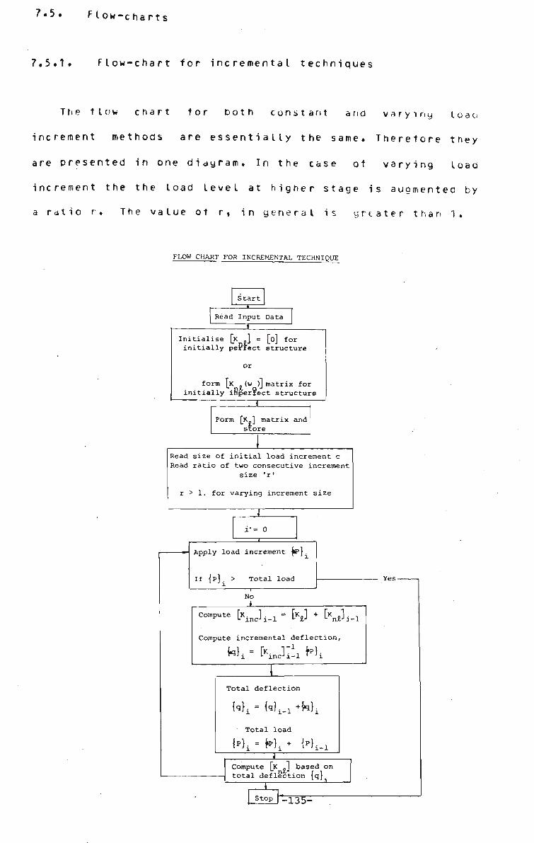
7.5. Flow-charts
7.5.1. Flow-chart for incremental techniques
Trie flow chart tor both constant and varying la
increment methods are essentially the same. Therefore th
are presented in one diagram. In the case of varying lo
increment the the load level at higher stage is augmented
a ratio r. The value ot r, in general is greater than 1.
FLOW CHART FOR INCREMENTAL TECHNIQUE
Start
Read Input Data i
Initialise [K .] = [o] for initially pePfect structure
form \K (W )J matrix for initially imperfect structure
Form [K.] matrix and store
Read size of initial load increment c Read ratio of two consecutive increment
size 'r'
r > 1. for varying increment size
i'= 0
Apply load increment M~l If {p}. > Total load
No
Compute [ K . J ^ = [K£] + [ x j . ^
Compute incremental deflection,
ril i L incJi-l ' Ji
I Total deflection
Mi - W^ +Wi Total load
I Compute [K -J based on total deflection {q}.
Stop ]-135-
Yes-

7.5.2. Flow-chart for step i t e r a t i o n
The flow chart for step iteration is more involvea than in
the incremental solutions. The solution is assumed to have
converged when the ratio of the incremental deflection due
to a cycle and to the totat deflection at any stage is less
or equal to a convergence Limit. The convergence limit is
set at U.57. tor the nonlinear elastic analysis. The term
cycle, used herein, represents the number ot iterative steps
within an increment. The limiting value of the. cycle within
any incremental step is taken as five.
-136-

FLOW CHART FOR STF.P TITRATION
Start
Read Input Data
I Initialize [K £] = [0]
n=0
Read load increment sizes Read'ratio of two consecutive increment, (r) .
r = 1. for constant increment > 1. for varying increment
Form [K„]=[K. ] (first increment!)
n = n+1 i = 0
Read increment of load {P ] n
{V = <P>n-l + rtPn}
Apply increment of load {P }
Calculate incremental deflection
{V = CKinc {*K-l*rl {V
Total deflection
<<>n = {q},.! • ikj
Calculate
^ - "inc^V^ T
Calculate i = i+1 residual load within an increment
U P ^ i - <P><APn}
<Vi " CKinc< 5<}n 3 {APn}i
<qn> = <qn) • <\)i
Total deflection {q}R = {q}R + tAq^j
I
-137-

U P } , = {P > - [K. ({q},,)]"1 {q„> n if-n n i-n n ^n
< V i n ^ ' i n c ^ V ^ ^ V i
{qn)n - {qn> • {Aqn}.
{q} = {q} + Uq }. n n n nn va
Test . /. \ _ ^ maxtAq }. Compute n l n
<£ e = 0.005
NO
max{q } n
YES
Print results
Test
{Pj < Total load
T STOP
•' END
NO
-138-
CHAPTER b
APPLICATIONS
8.1. Genera I
The numerical examples solved in this thesis may be
grouped into the following three c a t e g o r i e s :
(i) Large deflection analysis ot beam and p l a t e s .
(11) Large deflection analysis ot plated structures such
as stiffened plates ana folded plates including
box-girder s t r u c t u r e s .
(111) Large and small deflection elastoplastic analysis of
p l a t e s .
The main objective of analysing various plate problems
Is to assess thf applicability ot the finite strip methoc
1n solving nonlinear s t r u c t u r e s ^ while plated structures
are Investigated to demonstrate the potential of the finite
strip procedure to handle relatively more complicated
n o n h n e a r s t r u c t u r e s . The detailed account ot the problems
in (11) and (111) are presented m the subsequent s e c t i o n s .
An Important development ot the present research is,
that the finite itrlp methoo now can be used to analyse
states which have initial o u t - o t - plane d e f o r m a t i o n s . The
Plate structures which are iwperfectt have been solved by a
Plecewlse incremental method, white a combined incremental
-139-

and iterative(step iteration) procedure has been adopted in
analysing the plates which are geometrically perfect. The
step iteration procedure developed, is found to be
unsuitable tor solving initially in.perfect structures and
may need further investigation to determine the reasons.
It has been mentioned before that the nonlinear
lead-deflection relationships (Fig. 8.2-3,6-9, 16-1V) for
the structures considered in (i) show a steep graoient at
the initial stages ot loading and the curve gradually
becomes flatter at higher loads. These characteristics
allow the use ot varying load increment sizes; i,e smaller
load steps initially and then followed by larger loaa
increments. In the present research, the formula proposed
by Yang(142) to determine step size at any increment, is
adopted. Following Eqns. 7.3-4, the non-aimensionaIised
load "Q" for the uniformly distributed load case may be
written as ,
PA* Q = £h- (8.1)
= c
At any stage *n' the total load *ti' is given by
? i-1 cd-r""1) Qt = l
cr = (l-r) (8.2) i=l
For concentrated and patch loaa cases "Q" is defined as
tot low s,
PA2
n = ~ (8.2a) * Dh
-140-

where
A
C
D
E
h
i
n
P
P
r
a,6
= l e n g t h ot the s t r u c t u r e
= initial nondimensionaI load
= fle xtura I rigidity
= modulus of elasticity
= thickness of the structure
= incremental step
= total number of steps
= intensity of uniformly distributed load
= concentrated load or total patch load ( pxaji.S
= ratio ot two consecutive load increments
= pat c h di mens i ons
The left hand s i d e s of E q n s . 8.1 and is.2 r e p r e s e n t the
non-dimensionaIised loaos tor various types ot loadincs.
The numerical values of c and *r~, vary from problem to
proolem, the adopted values are mentioned in the appropriate
places.
S.2. Illustrative Examples on Beams and Plates
8 . 2 . 1 . B e a m s on h i n g e d s u p p o r t s
The r e s u l t s tor the m i d s p a n d e f l e c t i o n tor b e a m s on
immovable(hinged) supports with uniformly distributed and
concentrated load at miaspan are presented in Figure fi.2.
Roark(IUb) used variational energy method to obtain the
exact solution of the problem.
-141-
The degree ot convergence of the finite strip solution
depends on many factors such as step size, number ot
harmonics, first Increment ot load, "c etc. A detailed
investigation to obtain the optimum limits of these
parameters is not included in the present research. For team
problems, trials have been made to determine the initial
load increment. In order to achieve the optimum initial
load increment ~i' a beam supported on two hinges has been
analysed tor various "*c" (Eqn.8.1 > values. The strip
division and harmonic number(m) have been kept unchanged.
The size ot subsequent load steps is governed by Eqn. 8.1
and/or 8.2. Five non-zero harmonics have been retained in
the finite strip analysis ana only two strips were usee to
simulate the beam (Fig. 8.2). By increasing the number of
strips there was no significant refinement in the results.
The load versus central deflection curves tor the beam
subjected to uniformly distributed and concentrated central
load are given in Fig. 8.2. These results are compared with
exact solution due to Roark(105)t and a satisfactory
correlation is noted.
K.2.2. Simply supporteo square plate
Four simply supported square plates having the initial
out of plane flatness ot various degrees, are considered.
The in-plane movement at the edges of the plate is assumed
restrained. The tour plates posseses initial imperfections
which takes the following forms,
e, • Ix „ . fry (8.3) w w Sin sin —j-w o c B A
-142-

w {w } Sin **%• (8.3a)
where
A(length of plate) = a d e n g t h of strip)
(«J w ci 8 . ci
w CD
e
(8.3b)
wfc = initial deflection at the nodal lines
wo = initial deflection ot a strip
wc = maximum deflection (at centre) of the plate
w0 = initial deflection of the whole plate
x,y are the co-ordinate axes defined in Fiu. b. c
w c i ' w •' * * ^n Eqn.SJfc are obtained by substituting
appropriate values nodal line co-orainates x (x co-ord of
nodal line i) in Eqn. 8.ia.
It may be no*ed that Eqn. 8.3 conforms to the boundary
conditions of the plate. To investigate the effects ot
imperfection on the load/deftection relationship, tour
values of the out of plane deformations defined by "c/*1 are
included. They are U.,.i>,1. and 2. respectively. "h" is the
plate th ickness.
For tour wc/h ratios, the computer results for the
central deflections of the plates are plotted against the
loaainglFig. 8.3). All the results are obtained by stepping
the non -dimensiona I ised load, *u' using Eqn. 8.1. The
numerical values of *c'and "r" used are specified in Fig.
8.3. Five strips have been used over the symmetrical half
of the plate and five harmonics (3 non-zero) have teen
-143-

retained in solution.
The results are compared with Levy's solution for the
perfect plate, and tor the imperfect plates, the finite
element solutions due to Yang(143) are used as the basis tor
comparison. In all cases the proposed method gives good
accuracy. This indicates that the polynomial approximation
of the assumed initial imperfect i ons (.Eqn. 8.3) in the
transverse direction is acceptable. However this procedure
should be used with caution in the case of a fully-fixed
plate(Sec. 8.2.4). It may be noted in Fig.8.3e that the
initial imperfection otters additional stiffness to the
plate structure and the membrane action1becomes more prominent
at a. lower load when w /h Lrati° increases. ;
11 r'ca.n also be noted that the nonlinear load-de t lee t i on
curve is very steep at a lower load level and with the
increase of loaa the curve becomes tlatter(membrane action
preaominates). This phenomenon justifies the use of
continuously increasing load stepj(Eqn. 8.1-2) rather than a
constant one, thus saving much computer cost.
In Figs. 8.4-5 the resutts for the deflections,
benaing and membrane stresses have been plotted against
loao, tor a perfect plate ( w/h =0.) . The variation ot
bending stress at the centre 0 (Fig. 8.5b) of the plate due
to increasing uniformly distributed load is compared. A
gooo correlation with the finite element solution by
Cr i s11e td(33) is noted.
Figure 8.5a shows the load inplane stress relationship
tor the centre(O), of the plate and again a good agreement
-144-

with the finite element solution (33) is o b s e r v e d . The
non-dimensionaIised twisting stress(shear) due to bending at
the cornerlC) of the plate is also plotted against load(Fig.
8.4b). and the results compare well with the available
finite element resutts(33).
8.2.3. Simply supported rectangular plate
The nonlinear load-deflection curves tor rectangular
plates (aspect ratios 1. ana 1.5), are available in a
reference by Berger(13). The- plate is subjected to
uniformly distributed load. Berger approximated the plate
strain energy equations by neglecting the strain invariant
2 1 2 (*e = r- e - -T•£ . . ) . The finite element results due to
x y ** xy Yany(143) and finite strip results are touna to have
excellent correlation with the Berger's so tution IFig . 8.6).
The effect ot neglecting/strain invariant in the finite
strip formulation has not been considered. Berger has
provided the solution tor the load range, Q= U. to 1UU.
Therefore the effects ot neglecting £ ' in the higher loading
situation <Q> 100.) could not be assesed. The rectangular
plates with Initial imperfections have also been treated by
the finite strip method. The load-central deflection curves
for the range of'w/Ji- values(U. to 2.) are compared with the c
finite element solution due to Yang(14J). The results are so
close that little comment can be made.
-145-

8.2.4. Fully fixed rectangular p l a t e s
The rectangular clampea plates under the uniformly
distributed toad are investigated. Two cases where the
length-width ratio equal to 1.U ana 1.5 are exa in i n e d . The
assumed initial displacement function tor a strio may take
one of the following forms,
w = {w } Si in 2 Ty
(8.4)
where
w - W Sin a Sinh a - a Cos HY- _ Cosh
a = Sin: y - Sinh y
Cos y - Cosh y y = IT
HZ
(8.5)
(8.5a)
The finite strip d i s p l a c e m e n t f u n c t i o n is given by,
„ = {«»} where
Sin Sinh - a -a a m
Ura y VV1 Cos Cosh
a a (8.6)
Sin ym- - Sinh ]Xm y = nrrr
°m " Cos y - Cosh lira m
The initial displacement vector {wc> at strip level are
however obtained by substituting the x-coordinates ot each
nodal lines in the following equation.
w = w Sin o c
2 TTy_ Sin
2 TTX
B (8.7)
Eon. 8.4 used by Y a n g ( 1 4 3 ) , satisfies the displacement
boundary condition of a clamped plate. This situation is
different from the simply supported case where the
-146-

logitudinat v a r i a t i o n of initial displacement function is
z identical to that ot the finite s t r i p . The function (Sin
-rfy/B), representing the variation i n/y direction, does not
conform to the assumed *y" displacement variat ion IEqn . 8.5)
for a fixed strip(Eqn. A3.5). Due to thi s ,ilie f ot towi ng two
cases are identified and investigated.
In the Y direction,
Case 1.
Initial deflected shape is represented by Eqn.8.4 and
the finite strip displacement function is governed by
Eon. 8.5, called a "TYY' type.
Case 2.
Initial and finite strip displacement function are
both governed by Eqn. 8.5, called a ^YKC' type.
(i) TYY Type Initial imperfections
Four subcases relating to "TYY". type initial a e t t e c t i o n ,
where 'wc'lEqn. 8.4) have values U,.5h,1h and 2hj are
considered. The chosen values of c and r(Eqn. 8.1) are given
in Figs. 8.7 and 8.8. These figures show the
nondimensionalised load- deflection relationship tor clamped
plates having aspect ratios 1.0 and 1.5 respectively.
Comparing with the alternative analytic solution ot Levy and
Greenman(7U) tor perfect plate the finite strip solutions
are found to have high oegree ot correlation. It may be
mentioned here the polynomial function is capable of
-147-

TTX / TTX representing the Sin---; i . e / s q u a r e of v Sin ~-
function^ provided that enough number ot strips are
usea. In the above c a s e s , five strips over the half plate
are found to be a d e q u a t e .
(ii) " Y K C Type Initial Impp rtec t i ons
The impact of using two different types of functions
(i.e TYY and YKC) to define initial deflected shape
(y-axis) of a fixed plate can be seen in Fig. 8.9.
The use of * T Y Y ' ty^e imperfections in the finite strip
analysis gave r e s u l t s l F i g . 8.7-8) which have excellent
agreement with the finite element solution due to Yang(143)
while c o n s i d e r a t i o n of "*YKC* type imperfection did not
proauce comparable r e s u t t s l F i g s . « . V ) . Therefore it may
concluded that the shape of the initial deflection curve has
considerable influence on the load deflection relationship
for clamped p l a t e s .
Figure 8.1U shows the variation ot ratio* ot bending
moments M and M / , with the corresponding central moments x y
along the x-axis passing through the centre of a perfect
square clamped p l a t e , subjected to uniformly distributed
load. The results have been compared with the finite element
solution by Brebbia and C o n n o r ( 1 6 , 2 U ) . The linear elastic
solution ot the problem is also g i v e n . Figure 8.11 includes
the plots of extreme fibre inplane and bending stresses at
the centre of the clamped square plate due to U . D . loan.
It is surprising to note that there is no results for the stress v7~ rsus load in the reference 16 by Brebbia and Connor,. ;... fckor has compared these results predicted by the finite strip method
th those obtained by finite element theory (16) as .-quoted"'in 20.
rthermore for the convenience of uniformity of presentation the
realisation constants: of pressure (pA4/^) and of stress (NA2(l-y2)/sh2
reference 20, based on a square nLate of dimension 2A x 2A have been
Verted to pA4/Eh4 and *rA2/Eh2 of a plate having dimension A x A
the current DresentationiMg. 8.11). -i»*»-

8.2.5. Clamped square plate under patch loads
A clamped scuare plate (Fig. 8.12) subjected to a
constant total load(P) acting upon various patch sizes, is
considered to study the toad/ deflection load/ stress
relationships. For each case, a central patch loading with
4 different di mens ions (<ax$ ) < is considered ax3 being
U.1xU.1, U.2x.Q2 andU.3xU.3 (Fig. 8.12), and ax£' equal to
1.0x1.0 i.e when the plate fully loaded by a uniformly
distributed load. In general the loading is assumed to act
uniformly over the patch area. Each of the finite strip
solutions is obtained tor increasing values ot
nondimensionalised patch load •P.A2/Ehlf.
The results are summarised in Figure 8.13 which shows
the large deflection behaviour ot the problems. Tables 8.1
and 8.2 give the numerical values of deflections and
stresses by the finite strip and finite difference methods
respectively. Correlation between these two results art in
general satisfactory. The stresses are presented in a
non-dimensionaIised form for a Poisson's ratio of .3U0.
The non-d1mensionatisation is carried out such that for
assumed values ot concentrated loading ano plate dimensions,
the corresponding deflections and stresses (bending and
inplane) may be readily evaluated for a range of patch
sizes. The relationship between the non-dimensional
coett icients(P', «^',Ny< ,. M^ and My. ) and plate deflections
and stresses, used by Aalamid) is employed.
PE= PA2/Eh" w'« w/h "
„. 10-92 Ovn A2 10.920^ A2, (8.8) Ny = "Eh2 x Eh'
-149-

6.015 avi>A , y Eh
p = p x a x $
„, . 6 015 o ^ V x Eh
(8.8a)
In Table 8.2 the first row given tor each case, is the
linear small deflection coefficients obtained as a part df
general large deflection solutions. The small deflection
solution given by TimoshenkoH24) for a square plate under
partial loading agree closely with the coefficient ot the
present analysis (tor the smallest patch size, a^.3 =
0.1x0.1, the agreement is within 1.5%). It is interesting
to note that for given values of loading the difference
between the central deflections ot two paten size conditions
a x -3 = U.lxU.1 and 0.^x0.2, is only a tew percent for the
same loading (depending on the magnituoe ot loading). The
result suggests that for computing the deflections, it is
unnecessary to have accurate knowleaye ot wheel contact
area. The deflection profiles of the cases analysed are
shown in Fig. 8.13 tor the maximum values ot loading
considered CP*fePA2/3Ehl* = 1U0.0). Figures 8.14-15 show the
bending moment profile ot a plate tor maximum loading
(P'=100.). The bending moments ^have been evaluated tor each
case for comparison and are shown in Figs. 8.14-15 as a
ratio Wxc (moment at the centre C) in each case. These
figures also demonstrates that tor smaller patch dimensions
moments concentrate at the plate centre (tor actual values
Table 8.2 should be consulted). The agreement ot the
membrane inplane stresses are not as close as bending
stresses, particularly at tower patch sizelatf$ = .1 X.I). This
-150-

d i s c r e p a n c y ( S O X ) may be caused by a^ difference in
representation of the displacement function in the finite
strip and finite difference method. This problem should be
explored in detail before any final conclusion can be made.
It may also be mentioned that the finite strio method has
predicted the benaing and membrane stresses at the centre of
a simply supported platel u.d. load) satisfactorily with
those obtained by the finite element method(33). No such
comparison has been reported to prove the adequacy/the
finite difference method proposed by Aalami.
a.2.6. Clamned/S.S. rectangular plates
For u n i f o r m l y loaded rectangular plates with two
opposite edges simply supported and other two clamped
(inplane restricted), two cases where the ratios ot the
simply supported edge length, b to the clamped edge length
A, have values 1.U and 1*b are examined. The initial
deflection function is assumed to conform to the boundary
conditions. It is given as.
w = w Sin — Sin -*-O C B A
(8.9)
Four s u b c a s e s , where SJ.. nave values U.,.i>h,1.h and 2.h are
considered. The numerical values ot c and r are prdvided in
Fig. 8.16 where load central deflection responses have been
Plotted. The alternative analytic solutions tor plates with
no initial dettection are available in reference 13 ty
Berger. He (Berger) approximated the plate strain energy by
neglecting the second strain invariant. His approximate
-151-

results matched with the finite element solution by
Yang(142). However, Berger has given results up to wc/h
ratio of 1. only. For higher values ot the ratio the
validity ot Berger's assumption has not ppen tested.
Yang(142) also solved the large deflection problems in such
plates having initial def lect ions ot various degree*, using
the finite element technique. The same problem has been
considered here asabasis ot comparison with the finite strip
values(Figs. 8.16-17). A satisfactory correlation is noted.
8.2.7. Plates centrally loaded
A simply supported squar
point loads is considered. Fig
of central deflection with
element results(16,20). The c
along the centre line of the
B.3. The results have been com
and discrete element met
correlation is noted.
8.2.8. Convergence study
Validity ot the results in any numerical technique can
be established by investigating the convergence ot the
e p l a t e subjected to central
ure 5.18 shows the variation
load, plotted with the finite
entral deflection ratios w/wc
S.S plate is shown in Taote
pareu with finite element 116)
hods(20) and satisfactory
-152-
results. A s i m p l y - s u p p o r t e d sauare plate under uniformly
distributed toad p r o v i d e s the main vehicle for examining
convergence of-Hiefinite strip method as applied to large
deflection p r o b l e m s .
In order to obtain an e f f i c i e n t s o l u t i o n , the present
tinite strip p r o c e d u r e needs to consider a number ot
variables such as number of s t r i p s ( N E L E M ) ano harmonics
(NHARM), number of s e g m e n t s ( N I C R ) in a strip (Section 6.3)
and, the Gauss p o i n t s , NGX in x and NGY in y D i r e c t i o n s . The
later three v a r i a b l e s a r e used tor n u m e r i c a l integration ot
the stiffness m a t r i x .
It is not p r a c t i c a b l e to u n d e r t a k e a parametric study
considering all these v a r i a b l e s s i m u l t a n e o u s l y , therefore
the problem has been grouped into two p a r t s . In the first
part the v a r i a b t e s N I C R , N G X and N G Y t have been c o n s i d e r e d .
The optimum c o m b i n a t i o n of these t h r e e p a r a m e t e r s are found
to be 3,5 and 6 r e s p e c t i v e l y . The de t a i l s of the parametric
stuay is given in Chapter 6. With these values ot NICR, NGX
and NGY the second p a r a m e t r i c study is per f o r m e d varying the
number of strips and h a r m o n i c s to predict d e f l e c t i o n s and
stresses .
The numerical s o l u t i o n ot simply supported ptates using
several mesh p a t t e r n s show that the finite strip method
gives upper bound values of d e f l e c t i o n which converge
towards the true s o l u t i o n ( F i g . 8.19- ) . Also the extreme
fibre stresses at the c e n t r e ( O ) ot the plate show very
satisfactory c o n v e r g e n c e l F i g s . 8 . 1 9 - 2 o ) . A second
parametric study based on v a r i a t i o n of h a r m o n i c s reveals
that the use of 5 h a r m o n i c s and 5 strips over a symmetrical
half of a plate(Fig. 8.21)" is also adequate.
-153-

Although tne transverse mpiane stress at tiie centre of the plate
. to uniformly distributed load converges .satisfactorily even when
ow number of strips(4 to 6 over whole plate) are considered, but
transverse variation of inplane stress may not be predicted with
•j! accuracy. In the present research it has been found that
inimum of 8 strips(Fig. 8.19) are adecuate^ ' even higher, the better.
s difficulty stems from the fact that the inplane displacement
.ction is/linear polynomial which induces constant stress across the
th of a strip. An .identical problem will be faced in a finite element
lysis where the inplane displacement function for the element is also
ear. In the current research a parallel finite strip mesh(8 to 10 strip)
been used for the large deflection elastic(Fig. 8.19-20) and in the
stoplastic analysis(Sec. 8.4) to those used by Crisfield in his
ite element analysis( 33).
-/5ia

Although the transverse inplane stress at the centre of the plate
due to uniformly distributed load converges.satisfactorily even when
a low number of strips(4 to 6 over whole plate) are considered, but
the transverse variation of inplane stress may not be predicted with
hiph accuracy. In the present research it has been found that
a minimum of 8 strips(Fig. 8.19) are adeouate, ' even higher, the better.
This difficulty stems from the fact that the inplane displacement a
function is/linear polynomial which induces constant stress across the width of a strip. An .identical problem will be faced in a finite element analysis where the inplane displacement function for the element is also linear. In the current research a parallel finite strip mesh(8 to 10 stria)
has been used for the large deflection elastic(Fig. 8.19-20) and in the
elastoplastic analysis(Sec. 8.4) to those used by Crisfield in his
finite element analysis! 33).
-/53 a-

8 . 3 . N o n l i n e a r A n a l y s i s of Plated Structures
8 . 3 . 1 . G e n e r a l r e m a r k s
To trace the influence that the large deflections exert
on the plated structures, a folded and stiffened plate and a
box girder structures have been analysed.
Previous work related to the targe deflection analysis
of multiplate structures ot the kino( box, folded plate etc)
considered in this research have not been reported to the
knowledge of the author. In oroer to demonstrate the
applicability of the finite strip method to the large
deflection analysis ot such structures the following
examples are solved.
o Single cell box girder bridge on simple support | I
u p p o r t e u folded plate A o A simply supp
A simply s u p p o r t e c stiffened plate
All of the above s t r u c t u r e s have supports at the e n d s ,
which are diaphragms having infinite rigidity in the plane
and have absdtute ftexioitity in the out of plane direction.
The leading consists ot uniformly distributed load placeo on
the top exposed surface only.
-154-

8.3.2. Single cell b o x g i r d e r bridge
in this case a simply s u p p o r t e a box.girder(Fig. H, d'2a)
subjected to uniformly distributed load over the top flange
is considered. The purpose ot this investigation is to
observe the effect of number of harmonics on the
Ic.ao/det tec ti on and load/stress relationships tor a point
over the structure. Figure 8.2^-24 is a set ot computer
plotted graphs for deflections and stresses for a point
situated at the centre of the top flange of the boxgirder.
It may be noted from Fig. 8.22a that the eltect ot
nonlinearity on vertical (bending) deflection(w) is not
pronounced. This may be due to the fact that a stiffened
or box type structure has high resistance in vertical
dettection(w) and therefore the targe dettectidn
non-linearity in bending, is very small. This fact is also
proved in the load/bending stress response curve(Fig.
8.2:>). However the longitudinal and transverse inplane
strtss response with toad is highly nonlinear even at a low
loaa leveKFig. 8.24).
The effect of usiny an increasing number ot harmonics
on the deflections and bending stresses can possibly be best
understood by the stress/harmonic ana deflection/harmonic
response curves shown in Fig. 8.25. It is also noted that
load fending stress response is oscillatory at higher
loading stages but the maximum fluctuations diminish at
higher harmonic levels. A similar oscillation is noticed in
the longitudinal stresses ( Figs . 6,23b, 24b) but the latter
-155-

shows a tendency to converge as more harmonics are retained
in the solution.
8.3.3. Folded plate structure
A typical single bay simply supported folded plate(Fig.
8.26) is considered. The loading consists of uniformly
Distributed loading over the top surface.
The structure is divided into a fixed number ot strips
and analysed for various numbers of harmonics(7 to 13). The
load/deflection response is plotted by the computer in
Fig.8.26. The bending and inplane stresses are also plotted
against load for a section at the middle of the ridge(Fig.
8.27-28). As in the case of box girder problem some
oscillation in the results for bending deflection and
stresses are noted, which tend to diminish at higher
harmonic level and therefore, it is expected to provide a
convergent solution.
8.3.4. Stiffened plate structure
The elastic large deflection theory is also applied to
a stiffened plate structure subjected to uniformly
distributed load (Fig. 8.29a). The deflection and stresses
at the centre of the flange, are plotted against load (Fig.
8.2Vb). The structure ot this kino has high stiffness
against vertical deformation, the effect ot non-linearity in
-156-

the load/central d e f l e c t i o n response is very small and an
almost linear relationship is observed. However the load/
inplane stress relationship is noted to be highly
non11 near(Fig. P.31a). Therefore, incorporation of the
nonlinear strain-disptacement relationship in the analysis
ot stiffened plate structures shows that it has an adverse
effect on the stresses i.e inplane stresses tend to increase
very rapidly at higher toad stage, a completely opposite
phenomenon to that noticed in plate structures where at
higher load, the stresses(Fig • 8.5) tend to diminish. This
in turn means that the effect of the inclusion ot the slope
term(Eqn. 3.9) in the strain displacment equation has a
considerable effect on the inplane stresses in the plated
s true tures .
-157-

8.4. E l a s t o p l a s t i c A n a l y s i s of Plates
8.4.1. General remarks
The analytical procedure developed tor the targe and
small deflection elasto-plastic analysis, has been applied
to a number of plate problems The plate structures are
subjected to uniformly distributed loaa only. The following
plate structures are cosidered.
o Simply supported rectangular plates
o Clamped rectangular plates
The targe deflection elastoplastic theory/has been used
to solve a simply supported plate bending problem considered
by rtarcal(83), using the finite element technique.
In the present Investigation the collapse load has been
assessed in each individual case and compared with better
known sotutions(e.g • finite element, finite differences) .
Since a volume approachlvon Mises) has been adopted for the
elasto-plastic analysis, It has been possible to trace the
progressive growth ot plasticity through the volume of the
plates at any load stage. The elastoplastic domains are
mapped by means of computer graphics.
An elastic-ideally plastic material behaviour is
assumed. fcach finite strip is oivided into six layers
parallel to the middle surface to account tor the partial
yielding over the thickness of the plate. The incremental
method is used in alt solutions. The plate structures are
-158-

simulated by 4 stripslFig. 8.32) over its symmetrical half
and only three non-zero harmonics are retained. In order to
make an effective comparison of the results, variables such
a>, uetlections, loads unct stresses have been normalised
according ly.
Karcat(83) plotted toad and deflection curve in
imperial units.
Malaivongs et a I (7 7) used a non-Dimensional load(Q) and
defleetion(D) parameters:
,z . - wDx M" Q = %r and D = 1TE2
M = o
o
ffnh2
o
(8.10)
where
a = yield stress o
of the material
p = uniformly distributed load
D = bending rigidity of plate x
A = length of plate h = thickness of plate
-159-

8.4.2. Simply supported square plate
The elasto-plastic response of a uniformly loaded square
plate is shown in Fig. 8.37. Only four finite strips have
been used to represent symmetrical half ot the plate.
It can be noted in Fig. 8.37 that the plate yields at the
corner first (Q-1 U« )• ana vhe corresponding stress points move
to the centre. with further increase ot load, the plastic
zones at the corner and at the center advance forward to
each other and finally meet, thus forms yield zone across
the diagonal ot the plate. Further increment ot load can be
applied until the deflection at the center ot the plate
increases excessively with a very small load increment. The
collapse load(Eqn. o.8) Q= 27.5 is determined by
extrapolation (it necessary) and also became obvious by tte
load stage when the stiffness matrix becomes singular due to
due to collapse of the structure. The sequence ot plastic
yielding shown in Fig. 8.37, is also found to conform with
the yield line theory (65).
yield propagation as observed in the maps(Fig. 8,35-37) spreads
relatively wider band,this.. is due to the fact that the >-,.
size of the character used to represent a yielded point over
the plate is finite. Again the Gauss points have used to
trace the elasto-plastic condition ot the structure, which
do not lie strictly on the plate diagonals.
It may be mentioned here that the finite strip method is
-160-

based on a displacement field which is assumed to be
continuous and therefore it is difficult to model hinge
lines. However the trend of propagation of plastic flow
through the plate layers as predicted by the finite strip
method is extremely encouraging.
Table 8.4 gives the values ot collapse toad predicted by
the finite strip method. A comparison has been made with
exact upper bound and tower bound solutions obtained by
limit analysis by Belytchko and Hodge(12) as well as with
yield point load predicted by Backlund(9), Mataivongs et
a 1(77) and Marcal<83>.
8,4.3. Marcal's simply supported plate
A. .simply supported square plate 20x20x.25 inches subjected to an
uniformly distributed load is considered, and small deflection elasto
plastic and post-buckling analysis are performed using finite strip
method. It is well understood that a plate under large deflection
develops a considerable stiffening effect due to stretching of the middle
surface. Also in the post-buckling analysis the geometric effect due
to large deflection tend to compensate for yielding.
The plate is simulated by four finite strips over its symmetrical half
(Fig. 8.32). This finite strip mesh is equivalent to a 4x4 F.E. mesh over
a quarter of a plate used by Crisfield( 33). Marcal(83) used a
relatively firmer mesh( 4 triangles over a symmetric octant).
Figure 8,34 shows the ' pressure versus central deflection plots for
the small deflection elasto-plastic and post buckling analysis.
Tile stretching effects of the change in geometry in the post-buckling analysis is clearly demonstrated(Fig: 8.33). This effect continues to
Brow with the change in geometry in spite of yielding which
-161-

occurred(Fig. 8.36) at a point about .151 from the edge ot
the plate. It is interesting to note that in the small
deflection analysis the first yield is caused by the
bending and is located at the corner of a simply supported
ptate(Fig. 8.35) whereas in the targe dettection analysis
the first yield is caused by membrane stress(Fig. 8.36).
The yield load p = 11.376, predicted by finite strip
method is an under-estimation of the finite element valueslp
= 19.911). This discrepancy may oe attributea to the tact
that the finite element analysis assumes a full element
yield at a yiela load whereas in the present procedure the
structure is assumed to have reached the yield load when the
stresses at a Gauss point satisfies the yield criterion.
In the case of post-buckling analysis, Marcal( 83) noted that the yield
has been initiated at the centre of the edge of the plate while in
the finite s' rip procedure this yield has commenced at .151 from the
edge of the plate. This difference may be attributed to the fact
that it is difficult to emulate the stress boundary condition by a finite
strip analytic function . This is considered to be a limitation of the
present finite strip method. It may also be noted that Marcal assumed
full element yield instead of gauss point yield considered in the
present formulation.
There is an excellent correlation ot the collapse
load(Tab. 8.4) and load displacement relationshipIFig. 8.34)
predicted by both the targe and small deflection approaches
adopted in the finite strip and finite element formulations.
S.4.4. Clamped Square Plate
One half of a fixed supported square plate under
-162-

uniformly d i s t r i b u t e d load, has been represented by tour
strips which are divided upto six layers parallel t0 the
middle surface of the plate. The elasto-plastic
response(Fig. 8.38) is traced by plotting loaa versus
central deflection and the collapse loads are compared with
the best known upper-bound and tower-bound solutions due to
Belytschko et at and Hodge et al(12,6U). The finite element
solutions due to Wegmul ler (133/ and Walaivongs et al(77)
are also referred for comparison.
Figure 8.38 follows the yiela propagation through the
volume ot a fixed plate. The initial yield load is u=24,
and yield first occurs at the middle of the fixed edges.
Witn increasing load the plastic zones extend along the
tixtd supports until tne element at the center ot the plate
yields at Q=32. Further loading(Q=4U) spreads the yield
area from the center towards the corner along the diagonal.
Similar yield pattern has also been observed by
Wegmullar(133). The collapse loaa Q (Eqn. 8.9b) predicted
by the finite strip method is 6U.U.
In Taole 6.5, a comparison is made between the estimated
ratio of yield and collapse loads preaicted by the present
approach and oetter known solutions.
A moment profile(Fig. 8.39) is also drawn for a clamped
square plate under uniformly distributed load. The present
finite strip solution compares satisfactorily with the
stresses obtained by the finite element results by Ang ana
Lopez(4) .
-163-

8,4.5. Simply s u p p o r t e d r e c t a n g u l a r plate
A simply supported rectangular plate with an aspect
ratio of 1.5 is analysed by four strips over its symmetrical
half area(Fig. 8.40). The initial yield due to uniformly
distributed toad, occurs at the centre of the plate at
Q=5.33(Q=pA /M#) and this yield zone extends along the
transverse direction with increasing load. The corners ot
the plate yield at Q=9.333 and then merge with the plastic
zone at the cent-re with further increase of load. The
predicted collapse load is U = 1 3 . 6 7 . The collapse load
assessed by the finite element method(77) using the Tresca
yield criterion is 13.57. As in the other cases the yield
sequence over the volume of the plate at various stages of
loading ere traced(Fig. 8.4U) and has good correlation with
the finite element results(77).
8.4.6. Convergence study
The effect of the strip division on the predicted
coltpue load, has been studied i ri Fig. «.42« In this case
only five harmonics have been considered, as in the previous
situations. The plot of collapse load versus strip numbers
shows convergence as the number of strips is increased.
Perhaps a larger range ot strip divisions may be used in
order to achieve the final convergence. The present
computer program can handle problems where a structure has
been subdivided into a maximum of tour strip (over symmetric
-164-
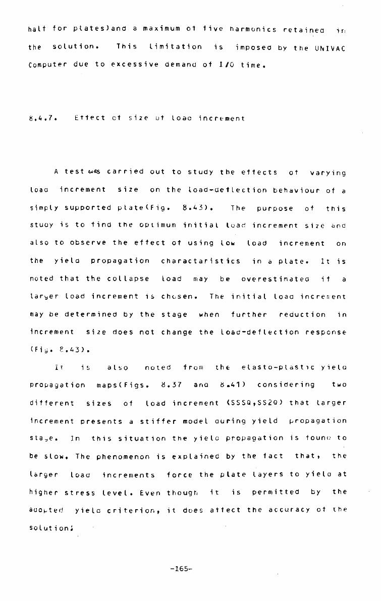
halt for p l a t e s ) a n d a maximum ot five h a r m o n i c s retained in
the solution. This limitation is imposed by the UNIVAC
Computer due to excessive demand of I/O time.
8.4.7. Effect ot size ot loaa increment
A test w«s carried out to study the effects ot varying
loaa increment size on the load-deflection behaviour of a
simply supported plate(Fig. 8.43). The purpose of this
stuoy is to find the optimum initial load increment size and
also to observe the effect of using low load increment on
the yield propagation charactaristics in a plate. It is
noted that the collapse load may be overestimated it a
larger toad increment is chosen. The initial load increment
may be determined by the stage when further reduction in
Increment size does not change the Ioad-deftection response
(Fly. 8.43).
It is also noted from the elasto-plastic yield
propagation maps(Figs. 8.37 and 8.41) considering two
different sizes of load increment (SSSQ,SS2Q) that larger
increment presents a stiffer model during yield propagation
sta^,e. In this situation the yielc propagation is touno to
be slow. The phenomenon is explained by the fact that, the
larger load increments force the plate layers to yield at
higher stress level. Even though it is permitted by the
auopted yield criterion, it does affect the accuracy ot the
solution*
-165-

9.
CHAPTER 9
CONCLUSIONS AND SCOPE FOK FUTURE WORK
9.1 . Conelus ions
Finite strip solution of large deflection behaviour of
elastic beams, plates ana plated structures (box girder,
stiffened plate etc.) have been presented. A noteworthy
contribution has been made in the area of elastoplastic
analysis of plates by the finite strip method. The
ayreement ot the results with the exact and with some better
known solutions (e.g. finite element, finite difference)
indicates that the finite strip methoo is a feasible one.
In particular, for the case of the nonlinear behaviour of
rectangular plates and plated structures, tnisltinite strip)
method is desireable and practicable one, since the
solutions by the methods other than finite elements are very
complicated. The finite element sdlution of the special
kino ot nonlinear structures such as toldea plate, stiffened
Plate and box girders is sometimes cost prohibitive.
One of the highlights of this presentation is that
computer graphics have been extensively used to plot ana
present the results from the theoretical analysis. By this
procedure an enormous amount of time has been saved which
would otherwise been required to plot the graphs manually.
-166-

Another important development ot this research is that the
propagation of yield through volume of a plate structure (in
the elasto-plastic analysis), has been traced by a computer
graphics program which depicts the continuous yield
propagation through tne layers ot the plates are dividea
into. The graphics output has been video taped and this
would certainty help to understand the complex
elasto-plastic theory as applied to a structural engineering
problem. Several points that have been mentioned previously
are worth noting again.
The incremental method and a step iteration technique
developed in this research have been used to solve large
detlection(elastic) problems in rectangular plates ana in
the multiplate systems respectively. The incremental method
has also proved to be valuable for the analysis of perfect
Dlates(elastic) and also for the elastoptatic cases. A
second type (varying) ot incremental method which
incorporates a continuously increasing load increment, has
been successfully implemented in the solution of imperfect
plates and of theptatedstructures.
The step iteration procedure is not suitable tor the
imperfect structures and in plated systems at this stage. A
further research may be undertaken to determine the reasons.
Secondly, in order to make an effective comparison of
the results predicted by the finite strip method the
variables such as loads, deflections and stresses, have been
normalised. This arrangement is sometimes preferable to
direct ptotting of the results in the absence of detailed
dimensions ot the examples solved in the available
-167-

l i t e r a t u r e s . P a r a m e t r i c studies have been resorted to tor
some structures (box girders, stiffened plates etc.) to
investigate the convergence ot results where no solution
was available for comparison.
Thirdly, similar to the finite element method the
accuracy of the results will depend on the adeauacy ot the
nonlinear finite strip stiffness matrix in representing the
part ot the nonlinear structure. The elements of finite
strip(nonlinear) stiffness matrix are the expressions
containing higher order analytic functions of higher power.
The elements ot the matrix are evaluated by the numerical
integration(segmented) which operates on the concept ot a
segmented finite strip. This proceoure(segmented) can be
usea for the numerical integration of any type of
complicated function( polynomial or analytic) easily and
accurately. The segementation technique also can be
tailored to deal with the special situations (nonprismatic
structures) where the discretisation in the logitudinal
direction has to conform with the geometric configuration,
such as change in cross-sectional property, of a system.
Fourthly the illustrative examples presented are mainly
the structures whose loading comprise the uniformly
distributed loads. Some examples which deal with
concentrated load and central patch loading, are also
described.
The deflections and stresses predicted by the finite
strip method have very good correlation with the better
knownlfinite element, series method etc.) solutions even
when only 3 non-zero harmonics are retained in the solution.
-168-
It may be m e n t i o n e d here that the use of only three n o n - z e r o
harmonics tor the c o n c e n t r a t e d or p a t c h - l o a d s i t u a t i o n will
in general not predict such an efficient s o l u t i o n especially
for the s t r e s s e s . The current i n v e s t i g a t i o n is limited to
the p r e d i c t i o n of only toad/ d e f l e c t i o n r e l a t i o n s h i p s in the
concentrated load c a s e s . Further studies may be carried out
tor a c o s t - e f f i c i e n t solution tor s t r e s s e s .
Fifthly the finite strip method has provided some
usetul i n f o r m a t i o n regarding the nonlinear behaviour ot
boxgirder, s t i f f e n e d and folded plate s t r u c t u r e s . The
response of inplane s t r e s s e s with load is highly n o n l i n e a r .
This above study has c o n s i d e r e d one aspect of the problem in
the n o n l i n e a r plated s t r u c t u r e s . Perhaps this type ot
structures d e s e r v e s further i n v e s t i g a t i o n considering vaious
other p a r a m e t e r s such as rise (depth)/span ratio*
width/length ratio e t c . The effect of rib p o s i t i o n i n g and
its relative s t i f f n e s s with respect to the flange ot a
stiffened plate on stresses and d e f l e c t i o n s , will definitely
provide very useful i n f o r m a t i o n for the design of such
s t r u c t u r e s .
In the area ot e l a s t o - p t a s t i c i t y , the tinite strip
method has p r e d i c t e d reasonably accurate solution for the
collapse load, which have been checked with the existing
solution also by the computer g r a p h i c s . The parity between
the computer g r a p h i c s output and the failure sequence
expected in the e x p e r i m e n t s , is t r e m e n d o u s . The collapse
loaos of s i m p l y - s u p p o r t e d ana clamped plates have been
predicted by the present finite strip m e t h o d . The
progressive yield map for these plates are also traced at
-169-

different loading s t a g e s . The c o m p a r i s o n of the results with
the existing solutions is made. In some situations the
tinite strip method tenus to underestimate the yiela load of
a plate structure when compared with finite element
solutions. This may be due to the tact that the tinite
element method assumes yield of an element while finite
strip method assumes yield at a Gauss point in assessing
yield load of a structure. However in some situations, the
collapse load of a structure is overestimated, which might
improve if more strips and harmonics (more than tour strips
and five harmonics) were used in the sdlution. The computer
program, PLAST cannot handle a problem where more than 4
strips and 5 harmonics are used, due to excessive
requirement of I/O (Input/Output) time. It has been
mentioned earlier that the intermediate computation and
processing of data requires enormous disc storage 12UUK) on
the other hand use of input/output units slows processing
time. A large deflection elastoplastic analysis ot a plate
takes approxmiate ten minutes of CPU where as input/output
units enhance this time to as much as three hours of
solution time. It is extremely difficult to obtain such a
huge block time in a busy University Computer and
consequently the expected successful run tor one job is only
one i n t hree days•
The accuracy of the results predicted by the finite strip
elastoplastic analysis also depends on the type of yield
criteria adopted and how it is implemented. Here a volume
theorytvon Mises) has been used where a finite strip is
assumed to be represented by a number of layers. The finite
-170-

strip s t i f f n e s s matrix is e v a l u a t e d nun erically ty summing
the effects of all layers at each Gauss point over the
strip. Again a finite strip has been divided into a number
of segments(NICR). Therefore accuracy of the results would
definitely improve with the use of more NICRl NICR>3,
Chapter 6) and more layers and possibly more Gauss
points(i,e NGX>5 and NGY>6). A larger parametric study may
be undertaken in future if any doubt exists in this regard.
In most ot the problems solved in this research the
numerical values of NICR,NGX,NGY,NSLICE are chosen as
3,5,6,6 respectively. These values are relatively much less
than used in an equivalent finite element analysis by
Crisfietd(33). Needless to mention that with the
cbvetof>*1rt*n4' of the segmented tinite strip procedure the
method can be used to model non-prismatic structures which
were so tar suitable tor the finite element analysis only.
In a numerical method such as finite strip, the collapse
load may be determined either by extrapolation ot the
toac/displacement curve or from the load level when there is
a numerical failure of the stiffness equations. The second
condition seems to be more appropriate in the present
situation, since at neighbourhood of the collapse load, the
load step is automatically reduced substantially (1/20th) in
order that the collapse load is predicted as closely as
possible. This is achieved by checking the ratio of two
consecutive displacement increments due to current and
previous increments of load. If this ratio is more than a
certain prescribed valued. 75) the solution procedure moves
backward by one step and the solution process recommences
-171-

w i t h a r u c b t o w e r load i n c r e m e n t s i z e .
Furthermore, the ninety percent of the diagrams
presentea in this dissertation have been prepared ry using
computer graphics packages and they are identified as
C.P.(Computer Prepared). The hand-arawn diagrams are marked
ai. H.P.d'.arualy Prcpareu). It may be worth n.entioninn here
that the main advantage ot using computer graphics tor
plotting purposes lies on the fact that it enables the user
to charce the scales, the tick marks and symbolCyield map)
eic. ace r rainJ to the needs. Tnus high quality arawings
can be prepared very accurately and quickly. Especially the
yield maps could not be hanatea Letter by any other means
exctctin: by the elastic methoa.
Tt.p yitla niaps, the loan-deflection curves and tables
tor collapse loaa proviae the complete picture ot the
response ot a nonlinear elasto-plastic structure. In the
CdSt ~+ nonlinear elastic structure the loaa/aeflection and
I o a •„ / b ' r '• s s rest-C rises have teen prepared by usint. conputer
graphics techniques.
Through a number of applications, the finite strip
ret noa has been nroved tu be a useful tool for solving
n niinrar structures. M r.ew application ot the tinite strip
method in dealina with non-prismatic beam problems can be
consiuerec us a ty-product of the present research.
ihe segrented finite strip procedure was applied to a
simply supporter nonpiisratic team tor computing elastic
linear deflections. This type ot problem has not been
solveu ly tinite strip procedure before. The finite strip
results are compared to the conjugate b e a T method and
-172-

correlation is s a t i s f a c t o r y .
The tinite strip method was applied to the nonlinear
problems in initially imperfect p l a t e s and the results
matched with the finite element s o l u t i o n s extremely
sat i s t a c t o r i t y .
It may be m e n t i o n e d here that finite strip analysis of
non-linear s t r u c t u r e s may not oe as efficient as linear
elastic analysis in terms of the core memory and band-width
ot the s t r u c t u r a l s t i f f n e s s matrix r e q u i r e m e n t s . The
reasons for r e l a t i v e l y higher c o m p u t e r costs stem from the
fact the finite strip s t i f f n e s s m a t r i c e s are /....coupled, A
large amount of c o m p u t a t i o n s are n e c e s s a r y to evaluate the
d e f l e c t i o n s ( l a r g e d e f l e c t i o n a n a l y s i s ) , and d e f l e c t i o n s and
stresses ( e l a s t o - p l a s t i c a n a l y s i s ) at the Gauss points over
the strips for each h a r m o n i c . This ano some other necessary
intermediate p r o c e s s i n g of data are p e r f o r m e d before the
actual solution of the s t r u c t u r a l stiffness matrix is under
taken. The extra c a l c u l a t i o n s needed and the core memory
required to store i n t e r m e d i a t e oata may o f f s e t , the gain
made by the inherent a d v a n t a g e s of the finite strip in the
elastic a n a l y s i s of s t r u c t u r e . To make the tinite strip
method c o s t - e f f e c t i v e the computer programs must be
optimized before a realistic c o m p a r i s o n of the computer
costs can be m a d e . The computer p r o g r a m s d e v e l o p e d in this
research are not fully o p t i m i z e d at this s t a g e .
Lastly this dissertation has been prepared on the
computer and the output has been obtained by using the DOC
Processor which is d e s i g n e d tor making a thesis from a
-173-
source input t e x t . N e e d l e s s to m e n t i o n this helps
tremendously to update a draft with minimal difficulty.
9.2. Scope for Future Work
In the present research two
have t>per\ solved by the finite
further work may be expanded
(including combined nonlinearity)
9.2.1. Elastic large deflection
The large deflection analysis of plateo structures may
be subjected to further parametric stuay with regard to
strip division, aspect ratios to conclusively prove the
adequacy of finite strip method. Furthermore, in the case
ot stiffened plate the effect ot changing the ratio ot
stiffnesses of stiffeners to the main plate tor the maximum
stress, will be useful design exercise. The variation of
the in-plane stress across the flanges of the stiffened
plate and box giroer section should be studied in detail.
The effect of initial imperfections on the nonlinear
response of platea structures may be considered.
The determination of the optimum load increment size in
the incremental method so that the expensive step iteration
method can be avoided, is highly recommended.
types of nonlinear problems
strip method. Therefore
into two, possibly three
di rect ions.
-174-

9.2.2. M a t e r i a l and c o m b i n e d n o n l i n e a r i t y
In this analysis, the volume theory due to von Pises'
has been adopted. The elastoplastic analysis ot plates may
be performed using the Ilyushin yield criteria(Area
Approach) which demands less computer time. A computer
program to solve plate problems based on the area approach
is under development. This study has not been pursued to
limit the scope of this dissertation. both of these
approaches(area and volume) may be extended to predict the
collapse toads in plated structures. Large deflection
instabilty problems considering material nonlinearity of the
structure may be attempted within the basic framework of the
finite strip method. The theory of probability may be used
to predict the probabitty ot failure by collapse loadin the
elastoplastic analysis ot structurs. The author suggests
that a probabilty function based on any yield criterion
(such as von Rise's, Eqn. 4.6) will be a good starting
poi nt.
-175-

•H
u v w H id
u •H
ft
H3 (1) •U
o ? & * w c
•H >. I H +J 04 H
e -H •H 3 W «
1
c •H
C 0 •H
(fl •H > •H Q
ft
10 ffl
u H (0 O •H M +J CD
0 •H 4-1 •H T) C 0 0
<D Cn T3 0)
T tfDIHiaWWAS
SZi —r
v
CD Xi
c 0 •H 4-1 •H
c 0 ^
a
LU
o_
(/)
»—» CO
>
Q
0. I—I
I UJ
r>o UJ
o 04
-176-

. x,u
y»v
FIGURE 3.2 COORDINATE SYSTEM (hp)
-177-

»- X
STRESSES CORRESPONDING TO THE INITIAL AND DEFORMED CONFIGURATION OF A PLATE (a)
r .
i
z 1
V ^ * •
u(x,y>
PLATE SECTION SHOWING INPLANE DEFORMATIONS IN
DEFORMED CONFIGURATION (b)
FIGURE 3.3 LARGE DEFORMATIONS IN PLATES(hp)
-178-
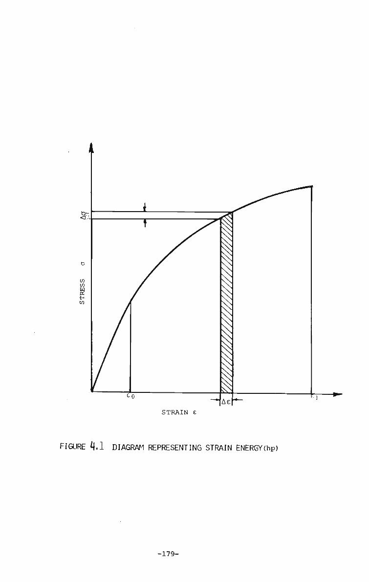
STRAIN £
* M DIAGRAM REPRESENTING STRAIN ENERGY(hp)
-179-

Boundary Condition at the ends for a Simply Supported Strip (u = v = w = 0)
FIGURE 5,1 A TYPICAL FINITE STRIP WITH RESTRAINED
INPLANE MOVEMENTS IN X AND Y DIRECTIONS(hp)
-180-

>-im
x \<
X
k
CQ
* *
O ^ UJ 2
| £ co y
1 1-T: in CO
br1 a. UJ DC
Q. »—4
or l-co
£ I—H
< <
CO I — 1
> »—» Q Cu
or CO
P- CL
X!
(0
u
5 UJ
5 UJ •z. »—H
_l
§ i£ •z.
g W—H
s S» o u_
<
H *i >- Q
<E g f — H i
CO •-^
> • — 1
Q
Q. 1 — *
or CO
CNI LO
*•—N
ft •+~f
H) CO
5 a S? 0-
CO
>] fe CO v- co £ 3 0-u_ o CO H-H
CO >-_J <
IS.
-181-

2
bk -• B A
B
\
X
SIMPLY SUPPORTED PLATE HAVING
INITIAL DEFLECTION ™c AT CENTRE
GAUSS POINTS
SEGMENTED FINITE STRIP h.
LENGTH BREADTr NUMBER NICR
A = 1.0 \ B = 1.0 OF STRIPS
= 3 w /h = 0.
c = 6
=
,1
ID
u
r
NGX = NGY = EX =
AICR
= 5 = 6
b 1 = .316
= 1.15
= 1.0 333
-
FIGURE 6.1 STRIP DIVISION IN A S.S. PLATE AND A SEGMENTED
FINITE STRIP(hp)
-182-

IST= 5
c m en
z
T|
z i—i
FVl CO
13
CO
z m co co 5J »—i
X
H i— i
n a
•a
CO I — *
> Tl
z
CO H
CO
m CO CO
yXJ
X
o ^3
c_ CO -1
II
co1
Z
0 I—*
X
Oi
-c Oi o>
CO
I
~ 3 —. co co m z c H Z 5 1 &
^-o —I
-3 co* D rn
c_ H co
TJ CO
5S* R I
00
CD
CO CO
CD
oo en 00
00
00
»0
^1
CO
en
<n ~J
-j
en
en
en CO CT«
en Ul ON
en en
en
en
en
In co en
en en en en en ^j Ul 00
*>
co
en
en *>•
CO
CO
CO
N to CO
co
co en CO
en co
"T3J CO
VJ
IV
^ *» to in
en to
00
h1
H M JJ
h-1 •fc»
H en
en i-1
H CD
^
C/3
3
3
-183-

Layer of the Plate
T h
I
—f *-Assui
A "" Assumed linear variation of the s of E(a ) Matrix
z
FIGURE 6.3 LAYERED PLATE MODEL IN THE FINITE STRIP ANALYSIS(hp)
-184-

L/i) L/2 •L A-- C i ) - - ' -
1
WU ' (i)..
rfftl
ELEVATION
|*- NICR = 8 - ^ NICR = 16 - j — NICR = 8 - ^
PLAN Beam simulated by Two Strips
FIGURE 6 A A SIMPLY SUPPORTED NON-PRISMATIC BEAM(hp)
-185-

SYMBOLIC LOAD-DISPLACEMENT CURVE STRESS-STRAIN CURVE
FIGURE 7.1 NON-LINEAR CURVES(hp)
-186-

A
U
I J. ± b NOI1031330
1 £ i g
u z
• ° 5 ro O M -J
Ir-O
a
CN i—.
^ e UJ
o •
UJ or
I" £+£
co
< t-z bH UJ or u z •—•
ui CO 1—*
5 CJ UJ w—«
o_ >-CU
co £ 5 u 25 « — « 1-u n LL 11,1 Q 1
_^
£ CO
K rj
uT H or a.
1
CNJ
r<
5
-187-

r-uV~ iT"
D.
1 -c -J 'C-
J r, ..
i / O- / <r /
1 / r /
• a
•
/ A -H
c
> »-
M*„^ {q }i+l
• n —
DEFLECTION q
W
FIGURE 7.3 C0M3INED INCREMENTAL ITERATIVE -(STEP ITERATION) PROCEDURE(hp)
-188-
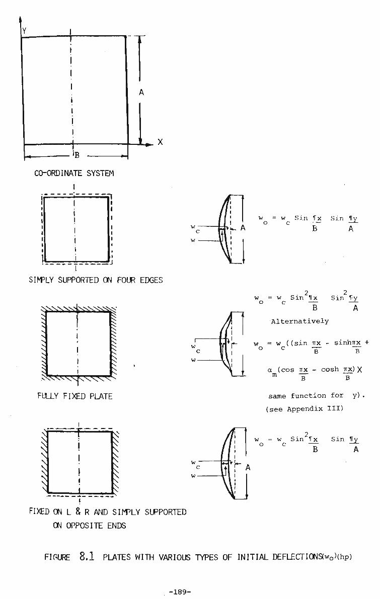
CO-ORDINATE SYSTEM
w = o
w Sin llx Sin 1Iy_
SIMPLY SUPPORTED ON FOUR EDGES
.WvVsNiV
FULLY FIXED PLATE
2 2 w = w Sin Ux Sin Uy o c — —
B A Alternatively
w = w ((sin TTX - sinhTrx +
° c "B" T a (cos TTX - cosh TTX) X m T B
same function for y) .
(see Appendix III)
FIXED ON L & R AND SIMPLY SUPPORTED
ON OPPOSITE ENDS
w = w Sin Ux Sin Ky ° c ~TT —7
B A
FIGURE 8.1 PLATES WITH VARIOUS TYPES OF INITIAL DEFLECTI0NS(wo)(hp)
-189-

10 T
^Z nimu'tm A
I I I I 1 . . T I T T T
Y~~ A if
p = Load/unit area
c = g£ =2.5 Eh
r = 1.15 NHARM = 5 Immovable Supports
1 1
Finite Strip Roark
(105)
I 0. 250 500 750
(pxA**4/Exh**4)
UNIFORMLY DISTRIBUTED LOAD CASE
1000
h/A ratio =* B/A ratio = V NICR NGX NGY
.30
.10
.0 3 5 6
STRIP DIVISION
2
n
.5
i 1 = PA 3
c '" 5h r = 1.15 NHARM= 5
Finite Strip Roark (105)
~ 0 20 40
(PxA**2/Dxh)
b. CONCENTRATED LOAD AT CENTRE
60
U>P*D CENTRAL DEFLECTION CURVES FOR BEAMS ON IMMOVABLE SUPPORTS(cp)
-190-
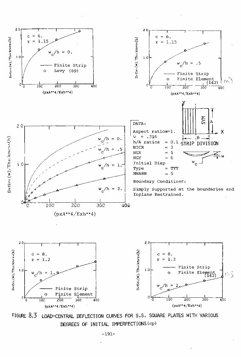
e it
C X
Q
2 0
Finite Strip Levy (69)
J_ _L ± IOC 200 300
(pxA"4/Exh"4)
40C
c
Finite Strip Finite Element
L i (142) 100 200 300
(pxA*»4/Exh*»4)
(VN
40C
if
DATA: CO
B L Aspect ratioa=l.
V = .316 h/A ratios = 0-1 STRIP DIVISION NICR = 3 NGX = 5 NGY = 6 Initial Disp Type = TYY NHARM = 5 Boundary Conditions:
Simply Supported at the boundaries and Inplane Restrained.
100 200 300
(pxA**4/Exh**4)
40w
20
i
c
i t
Q
20
10-
Finite Strip Finite Element
10C 200 300
(pxA**4/Exh"4)
40C
J5 t-
0
C o
1.0 -
c r
-
• V
= 8. = 1.
o
w /h = C _,
1
1
2
— Finite Finite
2^-*-"""
1
1
Strip Element
(142)
1
-
'->
100 200 300
(pxA**4/Exh**4)
40C
FIGURE 8.3 LOAD-CENTRAL DEFLECTION CURVES FOR S.S. SQUARE PLATES WITH VARIOUS
DEGREES OF INITIAL IMPERFECTIONS(cp)
-191-

2.0
V)
v\ (LI
C JsJ
u 4) 0) Q
Finite Strip Finite Element 133-)
100 200 300 400
(pxA**4/Exh**4) LOAD-CENTRAL DEFLECTION CURVE
if
CO
iB —J{C
T A
L STRIP DIVISION
DATA:
Aspect V
Ratio
h/A Ratio NICR NGX NGY NHARM -- 5 c =
= 1. = 0. = 0. = 3 = 5 = 6 = 6.
316 10
r = 1 .15
jn * to w -o *
PC + w>z
Boundary condition:
Simply supported at the boundaries and Inplane Restrained.
Finite Strip — o Finite Element
(33)
400
b. (pxA**4/Exh**4)
LOAD VERSUS TWISTING STRESS AT CORNER (c)
FIGURE 8.4 DEFLECTIONS AND EXTREME FIBRE BENDING STRESS<T );
ELASTIC PLATE UNDER UNIFORM PRESSURE(cp)
-192-

z y) * 01 * L. £\
* • > »
CO aj
#£ c : PQ
C o
12
0
Finite Strip(N = N ) —. o Finite Element7(33 ) x
100 200 300 400
(pxA**4/Exh**4)
a. LOAD VERSUS MEMBRANE STRESS AT CENTRE(o)
*Y
b <o
iB STRIP DIVISION.
^ X
DATA: Same as in Figure 8.4
* : in Ql —•"
* r*-CO \
c < c *
o
12
10
e
G
4
2
0
—
—
—
1
o/
1
© /
o
1 • >£'
/ —
_
Finite Element (33L
1 1 0 100 200 300 400
(pxA**4/Exh**4) b- LOAD VERSUS BENDING STRESS AT CENTRE(o)
FIGURE 8.5 EXTREME FIBRE BENDING AND MEMBRANE STRESSES;
ELASTIC PLATE UNDER UNIFORM PRESSURE(cp)
-193-

20r
tt
c
V
O
w /h = 0, c Finite Strip Berger (13)
JL J_ J 100 200 300
(pxA"4/Exh"4)
40C
0/
C
4,
c o
_L
Finite Strip
Finite | Element (143)
100 200 300
(pxA"4/Exh*»4) 400
C X
£ u
100 200 30C
(pxA**4/Exh**4)
>-CO
IB JL x
STRIP DIVISION
DATA:
Aspect ratios=1.5 V - .316 h/A ratio- =0.1 NICR = 3 NGX = 5 NGY = 6 Initial Disp. Type = TYY NHARM = 5 Boundary Condition:
Simply Supported at the boundaries and Inplane Restrained.
400
20
Finite Strip
Finite Element J L
100 200 300
(pxA**4/Exh*»4)
40C
20
e
o
10
c = 8 r = 1.2
— Finite Strip
o Finite
w /h = 2J1' c
_L ± 100 200 300
(pxA"4/Exh'*4)
FIGURE 8,6 LOAD-CENTRAL DEFLECTION CURVES FOR S.S, RECTANGULAR PLATES WITH
VARIOUS DEGREES OF IMPERFECTIONS(cp)
-194-
40C

c X u A H
O
Finite Strip Finite Element} (14 3)
20
100 200 300
(pxA**4/Exh'*4)
400
m v c u X
a. o
1 0 -
1
c = 8. r = 1.15
-
/
1 1
^** w /h = .5-^ c
Finite Strif o Finite El. -1 l (143)
100 200 300
(pxA*»4/Exh**4)
40C
/! /! 0
c
1 Q
0 100 200 300
(pxA**4/Exh**4)
DATA: CO
4- JL iB
STRIP DIVISION
Aspect ratios=l. V= .316 h/A ratio = 0.1 NICR = 3 NGX = 5 NGY = 6 Initial Disp. Type = TYY NHARM = 5 Boundary Conditions:
Fully Fixed at the boundaries.
400
20
t B X
i 4/
1.0
1 1 1
c = 8. r = 1.15
— o Finite El• e-""'''"
^ v * /h « 1.
/ . \ 1 !
""
20
400
c
4. Q
10 -
c r
1
= 8. = 1.
o
^
1
15
Finite Finite
w /h = c
1
l
Strip Element
= 2. o___ 0
1 10C 200 300
(pxA**4/Exh"4) " 0 100 2C0 300
(pxA"4/Exh*»4)
FIGURE 8,7 LOAD-CENTRAL DEFLECTION CURVES FOR CLAMPED SQUARE PLATES WITH
VARIOUS DEGREES OF INITIAL IMPERFECTIONS (cp)
400
-195-
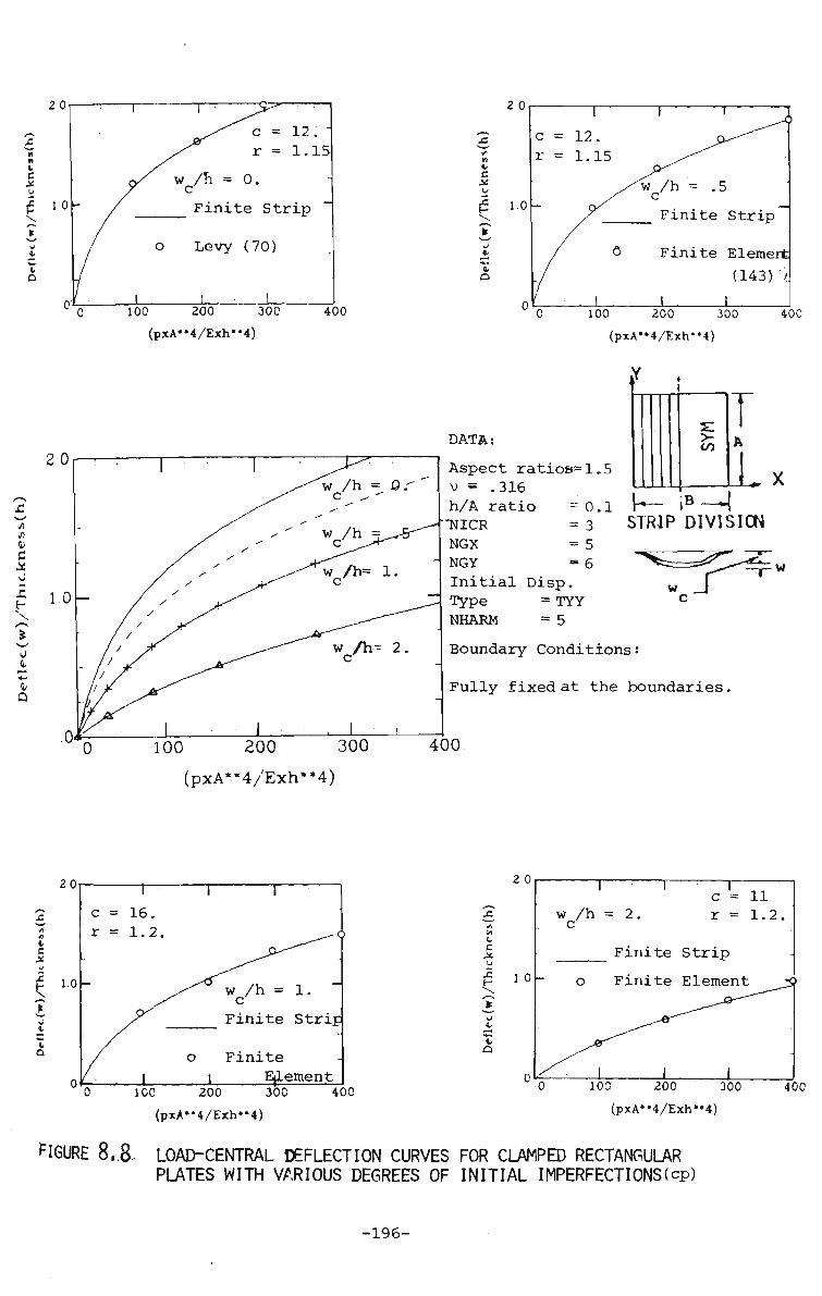
20
t
e x {= 10 s.
O'J
c = 12. r = 1.15
w /h = 0. c Finite Strip
Levy (70)
100 J_ 200 300
(pxA"4/Exh"4)
400
c o
2 0
1.0 -
1 c = 12. r = 1.15
— CK
/ ° -1
' • • 1
1 1 1
C ^ ^ ^ ^
"w /h = .5
Finite Strip
Finite Element (143)'/
1 . 1 , 100 200 300
(pxA*'4/Exh**4)
40C
0 it — i •4-1
Q
0 100 200 300
(pxA**4/Exh**4)
t 1
>• CO
_ jB — « .
t A
L i STRIP DIVISION
DATA:
Aspect ratioe=1.5 v = .316 h/A ratio =0.1 •NICR = 3 NGX = 5 NGY * 6 Initial Disp. Type = TYY NHARM = 5 Boundary Conditions:
Fully fixed at the boundaries,
400
c X
20
w /h = 1. c Finite StriE
Finite Element
2 0
100 200 300
(pxA**4/Exh"4)
400
c c
10
w /h = 2 c
c = 11 r = 1.2.
Finite Strip
Finite Element
10C 200 300
(pxA'^/Exh'M)
FIGURE 8,8. LOAD-CENTRAL DEFLECTION CURVES FOR CLAMPED RECTANGULAR PLATES WITH VARIOUS DEGREES OF INITIAL IMPERFECTIONS(cp)
40C
-196-

Deflec(w)/Thickness(h)
CD
<z m oo CO
O
CO
o m
^H
z » — 1 H 1-^
> r-• — i
•2 13 m 73 Tl m n H l-H
y CO «*->s
n •0 "*-*'
m -n G o H M
O Z
n c 73 3 CO
T| o TO o * w
*£ u
s TJ
5 Ft CO
70
m n G)
Q TJ
> TJ
B TJ
m
>
2?
o I
LH
*
Deflec(w)/Thickness(h)
n
«*
• ^
£ 5
*1
=£ £N O
3 TJ m
a CO
p £ m TJ
H m
TJ X > * *
\
m X + * *»
3 EC >
S l-i
II cn
25 CO K
II
en
2 r.i X
II
cn
a H n » n CO
ET •\ >
II
H
<-:
n 0J
o i> H >
O H C5>
-197-

C_)
» — I
or
u <
CO I — <
X
< CO
CU
u +J CO
o
VAVVAWVAV
)Xw/w
#
or
CO <
Q ...
LU CC
PQ § U_ Q
O w
or
& 06 LU
or ID CD
LL.
•
i—l
I
-198-
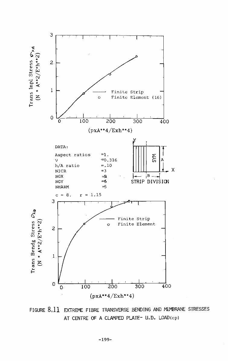
•c <K
^ tf\
*-> ro r—*
a. c >—i
</) c (0
c\T * • »
w V, CVi * * < * Z
<fl CM z> * ID *
is A
?z * CO w
c « a; < DQ
* (0 w
2
T r
0
Finite Strip
Finite Element (16)
100 200. 300
(pxA**4/Exh**4)
if
400
DATA:
Aspect ratios =1,
V h/A ratio
NICR
NGX NGY
NHARM
^=0.316
= .10
=3
=5 =6
=5
>-CO
iB STRIP DIVISION
L
c = 8. r = 1.15
3
1 -
0
— 1 — i — • —
-
— /
/
1 ' ' 1
» o
I I
J^*"t 1
• Finite Strip Finite Element
-
-
100 200 300
(pxA**4/Exh**4)
400
FIGURE 8,11 EXTREME FIBRE TRANSVERSE BENDING AND MEMBRANE STRESSES
AT CENTRE OF A CLAMPED PLATE- U.D, LOAD(cp)
-199-

2 — x
FIGURE 8. .12 CO-ORDINATE SYSTEM AND PATCH DIMENSIONS^)
-200-
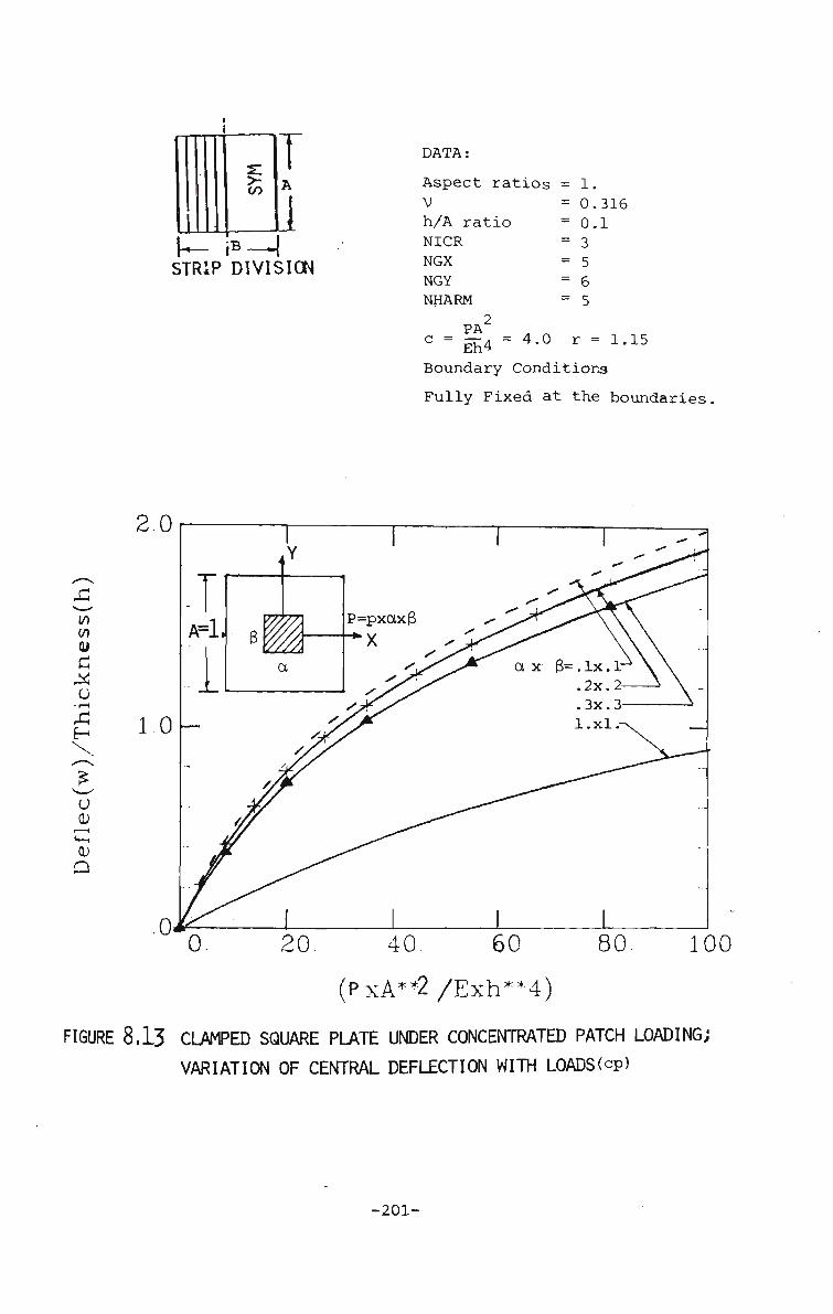
(
A
(B — ^
STRIP DIVISION
DATA:
Aspect ratios = 1. V h/A ratio NICR NGX NGY NHARM
2
= 0.316 = 0.1 = 3 = 5 = 6 = 5
PA
° = Eh4 = 4'° r = -1-15
Boundary Conditions
Fully Fixed at the boundaries
2.0
1.0
.0-
T A=l
0.
' 6
<
7-n
c YA
p= =pxctx$
/">
ax 3=.lx. 1-. 2x. 2-.3x.3-l.xl.
/>
1 80 20 40 60
(PxA**2/Exh*M)
8,13 CLAMPED SQUARE PLATE UNDER CONCENTRATED PATCH LOADING;
VARIATION OF CENTRAL DEFLECTION WITH LOADS(cp)
100
-201-
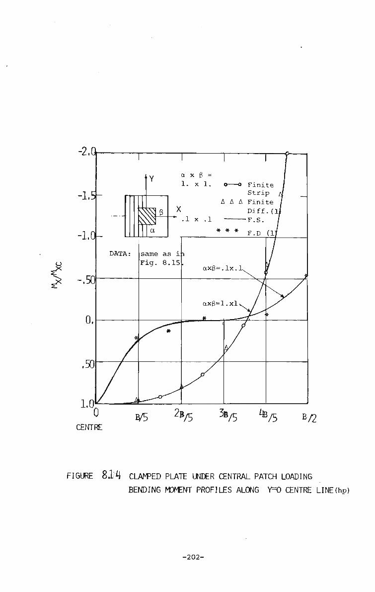
^
FIGURE 8 1 4 CLAMPED PLATE UNDER CENTRAL PATCH LOADING
BENDING MOMENT PROFILES ALONG Y=0 CENTRE LINE(hp)
-202-
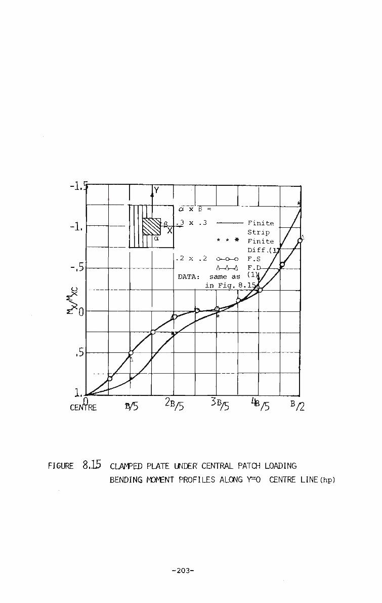
FIGURE 8,15 CLAMPED PLATE UNDER CENTRAL PATCH LOADING
BENDING MOMENT PROFILES ALONG Y=0 CENTRE LINE(hp)
-203-

20
10
c r
1 12. 1.15
' ' ^ - " ? O^--"^
^w /h = 0. c Finite Strip"
o Berger (13)
100 200 300 (pxA*»4/Exh"4)
400
c X
a. Q
Finite Element
100 200 300 (pxA**4/Exh*'4)
400
DATA:
Aspect ratios=1.0 v = .316 A/h ratio = .10 NICR = 3 NGX = 5 NGY = 6 Initial Disp. Type = TYY NHARM = 5
Boundary Conditions
¥ '•
s: >-CO
k- lB —
t A
I STRIP DIVISION.
100 200 300
(pxA**4/Exh**4)
Fixed on 1/& R edges and S.S, on opposite ends.
400
20
i,
c X (J
£
\
1.0
w /h = 1.0 c
Finite Strip
Fi«f£e Element
100 200 300 (pxA*»4/Exh'*4)
C = 16
r = 1.151 L
2 0
400
v C XI
H
0. O
1.0
w /h = 2.0 c
Finite Strip
Finite Element
100 200 300 (pxA*"4/Exh*»4)
400
FIGURE 8,16 LOAD-CENTRAL DEFLECTION CURVES FOR CLAMPED/S.S. SQUARE PLATES WITH VARIOUS DEGREES OF INITIAL IMPERFECTIONS leg)
-204-

2 0
/ wc
0
c
1 r
/h = o.
Finite
Berger
= 6
= lt.15
-
Strip -
(13)
1 100 200 300
(pxA*'4/Exh*»4)
400
c X
3
C v D
100 200 300
(pxA*,4/Exh"4)
40C
20 ^ / h = 6^ .
100 200 300
(pxA**4/Exh**4)
>-to
Lx STRIP DIVISION
DATA
Aspect ratios1.5 v =.316 A/h ratio = .10 NICR = 3 NGX = 5 NGY = 6 Initial Disp. Type = TYY NHARM = 5
Boundary Conditions
Fixed on L and R edges and S.S on opposite ends.
400
20 1
c = 8. T = 1.2.
1
w /h. C>e<
0
1
Finite Strip
Finite El.
1
2 0
100 200 300 40C
(pxA"4/Exh»»4)
tt
c X £ 1 0
\t Ht
t a
r—
c = 8. r = 1.2.
w /h = 2, c Finite Strip
Finit^tlement
100 200 300
(pxA«'4/Exh"4)
40C
8,17 li)AD-CENTRAL DEFLECTION CURVES FOR CLAMPED S.S. RECTANGULAR PLATES WITH VARIOUS DEGREES OF INITIAL IMPERFECTIONS(cP)
-205-

0-
0-
r PA
c = -- = .75 Dh
r = 1.20 NHARM = 5
o A
Finite St F.E.(16).
>-
co
Discrete STRIP DIVISION El.(2Q)
100. (PxA"2/Dxh)
200
8.18 VARIATION OF CENTRAL DEFLECTIONS VERSUS LOAD
IN S.S. PLATE UNDER CENTRAL LOAD (cp)
-206-
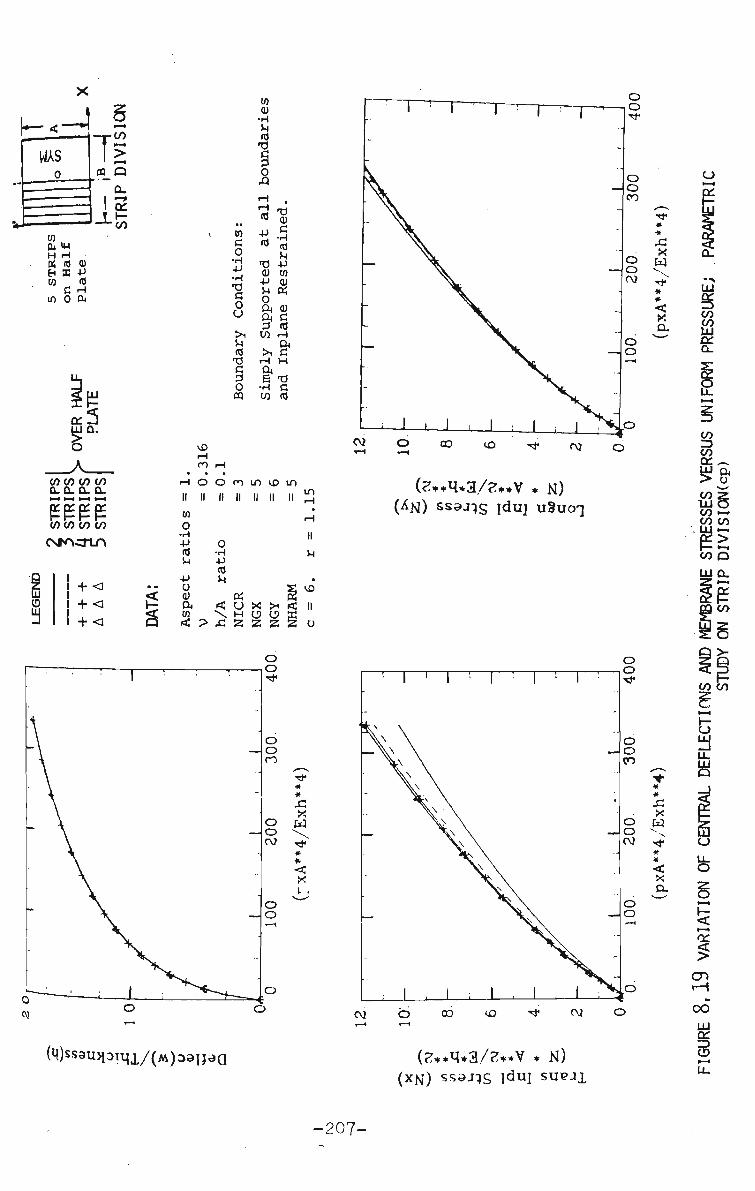
WAS Tto
> CD_Q
a.
IS w H H « (0 0) H SS 4J CO ffl C H
in 0 ft
CO CO CO CO 0. Q- Q. Q-M t—I I—• I—I
££££ CO CO to CO CSfACTLO
111 15
+ < + < + <
CO C 0 •H +J "O G O u >i M id TJ c 3 O m
CO CU •H
M id -0
B 0 A H H id +J id
T) CU +J
0
ft 3 CO
>i H ft 5 •H CO
TJ CU c •H id U +J
cn 0)
CU c id H OH
c H
TJ c rd
vD H ro H
• . • r-i o o cn m VD m II II II II II II
m
a
CO
o •H •P
<d +J
CD ft CO ri!
O •H •p id
m
? £\
U X >i H O O 2 Z 2
II
o
(e**q*3/?**v * N )
* *
Cd
< X
(M)ss3U3loiqi/(M)3aijea (?**q*3./?**V * K)
(XN) ss^JTS idui SUPJI
-207-

s
UJ CO
s s or 2 o >
LU
1-3 0-
\ CO CO CO to CL D- D_ Q_ •-4 *•* 1 — * (—t
££££ to to CO CO
csrocrLn
i i ! i i i •
i
+ < + < + < + <
ss o H w H > H Q
0< H « & C/]
TJ
c id < EH
3
CN •
03
cu u 3 cn •H fa
c •H
CO rd cu |
cn
(2++^*3/2**V * N.) «ffijt2 T ssaj^g §pu9g BSIAIJ,
c\j o> o n
<Tx (2**H*3/2**V * N) (2+*^*3/2**V * N)
''^oSsaJis puaH U S U O T
-208-

I 151
2
Q = 300
^: Q = 3 Q E h 4
5 7 9 HARMONIC NUMBER
11 13
a. CENTRAL DEFLECTION VERSUS NUMBER OF HARMONICS
to CO LU
to
12
10
0
,M-f' S t
\ c
-Q = 30C
"Q = 15C
i 1 \ 1
, 4
\_
>
1 3 5 7 9 11 13 TRANSVERSE INPLANE STRESS VERSUS NUMBER OF HARMONICS
1 3 5 7 9 11 13
c TRANSVERSE BENDING STRESS VERSUS NUMBER OF HARMONICS
FIGURE 8.2.1 VARIATION OF DEFLECTIONS AND STRESSES AT CENTRE OF S.S,
PLATE WITH NUMBER OF HARMONICS; A PARAMETRIC STUDY(hp)
-209-

p = load/area
iiiuuumnniuiimi
a- SIMPLY SUPPORTED BOX GIRDER SECTION
DATA:
Span = 1.0 V =0.316 c =16. r = 1.2
Loading Type:
Uniformly Distributed load over Top Flange
C ! u £1
O
a
0.
2 0
1 0
m
i i 1 •• ' •
LEGEND NHARM
+ + + A A A
-o-o-
1
1
1 . -
—
250
(PAW) 500 750
FIGURE 8.22 LOAD-CENTRAL DEFLECTION(AT TOP FLANGE) CURVES FOR
S.S. BOX GIRDERj U,D, LOAD CASEjcp)
-210-

X
z ip cs7 in * <D * i-i £\
•+-> *
w ^> C t « < * C 55
250
^AW1) 500 750
LEGEND HARMONIC
+ + + AAA 0-0-0
DATA:
same as in Fig. 8. 2'2
^ 55 V^n*
CO /! a; «-. +J CO DC TJ C CL
pa
PC
u 0 HJ
c\> + + £\ * W cv * < *
55
250 500 750
FIGURE 8,213 LOAD-EXTREME FIBRE BENDING STRESS(T0P FLANGE) CURVES
FOR S.S. BOX GIRDER- U.D LOAD CASE(cp)
-211-
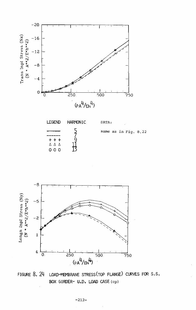
-20
x 2
CD M +J
CO
CM * *
* W \ CM
—• * ft * *
d 55 <d > — t-<
H
750
(PAVBA
LEGEND HARMONIC DATA:
+ + + AAA 0 0 0
9 11 13
same as in Fig. 8.22
>N
fc "•—' </)
-i-l
CO
a c fl oo a 0 J
,_ CM # * .£ » \ r\j * * <
*
55
250 500 750
CPAW)
FIGURE 8, 24 LOAD-MEMBRANE STRESS(T0P FLANGE) CURVES FOR S.S,
BOX GIRDER- U.D, LOAD CASE (cp)
-212-

CN £
CM Z •
CO to LU
to
15
LU CQ LU CO cr
5 10 15 TRANSVERSE BENDING STRESS VS. HARMONICS
DATA: Loading Type: Span =1. Uniformly Distributed Load V =0.316 c = 16. r = 1.2 on top flange only.
5 10 TRANSVERSE INPLANE STRESS VS. HARMONICS
15
FIGURE 8,25 VARIATION OF STRESSES AT CENTRE OF TOP FLANGE OF s.s. BOX GIRDERCFIG. 8.22)<hP>
213-

load/area
v.
« i—•«
CU Q
SIMPLY SUPPORTED FOLDED PLATE
DATA:
Span =1. V =0.316 c = 6.4 r = 1.15
Loading Type:
Uniformly Distributed load over top Surface only.
150
fe'AW)
FIGURE 8.26 LOAD-CENTRAL(RIDGE)DEFLECTION CURVES FOR S.S.
FOLDED PLATE- U,D, LOAD CASE(cp)
-214-
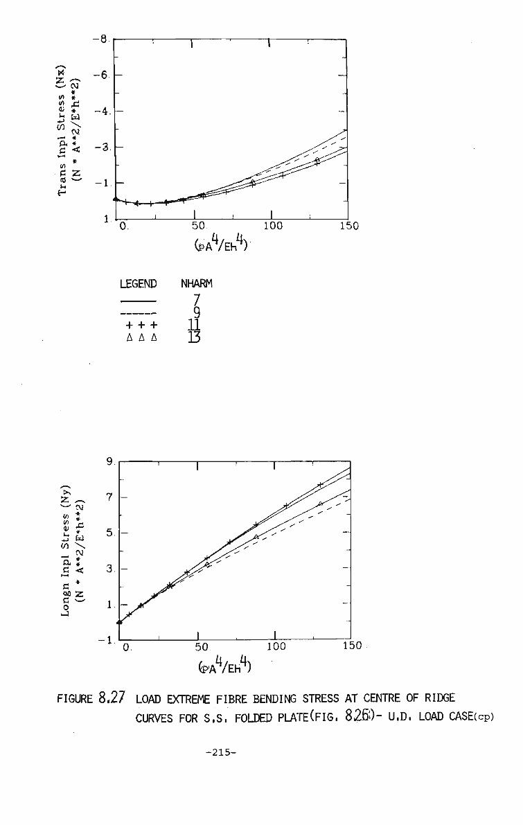
55 v—'
w (0 IL
on *- ft G i — <
CO C id t-t-
^-v
CM * * £1 *
cv * * <
# 55 "—
0.
LEGEND
__—__
+ + + A A A
50
(PAV)
NHARM
? 11 D
100 150
>s
55 ^ w cv
<" J J! * £ w CO \ - w
ft I £ < a * oa ss d ci o
150
^W) FIGURE 8,27 LOAD EXTREME FIBRE BENDING STRESS AT CENTRE OF RIDGE
CURVES FOR S.S. FOLDED PLATECFIG, 8260- U.D. LOAD CASE(cp)
-215-

X 55 ^ irt CM 10 CO
* *
DC T>
CD
m 10
C
CM * * <
150
LEGEND
+ + + AAA
55 to (0 CD U -i->
CO OJD
TJ
c CD m
CM * * £ * W CM
* < *
<J.
4.
3.
2.
1.
n u.<
— I
-
0.
i *' y^y
MP
M^
/ -
-
1 ' 50 100 1?
(aW) FIGURE 8.28 LOAD-MEMBRANE STRESS AT CENTRE OF RIDGE CURVES FOR
S.S, FOLDED PLATECFIG, 826) - U.D LOAD CASE(cp)
-216-

.125
i
p = load/area
iiiiiuiuiiumuumummiiumiimmu j — T - f f ^
,0125 ,01 n 1
.25 -T SIMPLY SUPPORTED STIFFENED PLATE
DATA:
Span =1. V =0.187
c = r = 1.15
Loading Type:
Uniformly Distributed Load on Top of Flange only,
3 c o -~* Xi
1/
Q
(PAV) 1000
FIGURE 8,29 LOAD-CENTRAL DEFLECTION AT CENTRE OF FLANGE CURVES
FOR S.S, STIFFENED PLATE- U,D. LOAD CASE(cp)
-217-

X 55 co CM w + CD *
M TJ
s CQ V)
(0 U
CM * * <3
500
(PAV) 1000
LEGEND NHARM
+ + + Q A A A 11 ooo 13
V £M (/) * CD *
h A CO w
TJ ^
c *
no
a o
4
3.
2.
1.
0 *
-
o.
J/yy y> v
'y •V •v
•v V
1
^ / -yyy / y/yy
X yyyyy /\y/y
y\yyyyy
yy"y yyy y
1 500
^yy^ yy%y'
IOC
(PAV)
FIGURE 8,30 LOAD BENDING STRESS AT CENTRE OF FLANGE CURVE FOR
S.S, STIFFENED PLATECFIG. 8.20- U.D. LOAD CASE(cp)
-218-

-15
x Z to CO
V u CO
CM *
*
CM •—> * CX *
c < co
S £ CO ^ ^ JH
E-
55 ^ ^- CM •</) 2
pj f
CO \ CM
ft I c < c * c >~' o _1
0 500
^/ErA 1000
0 500 1000
FIGURE 8.31 LOAD-MEMBRANE STRESS AT CENTRE OF FLANGE CURVES FOR
S.S. STIFFENED PLATECFIG. 8,29)- U.D. LOAD CASE(cp)
-219-

B
A -
-»-x
STRIP DIVISION IN PLATE IN ELASTOPLASTIC ANALYSIS
ayer n
CROSS SECTION OF A LAYERED PLATE
FIGURE 832 TYPICAL STRIP DIVISION AND LAYERED PLATE FINITE STRIP
MODEL IN LARGE AND SMALL DEFLECTION ELASTOPLASTIC ANALYSIS(hp?
-220-
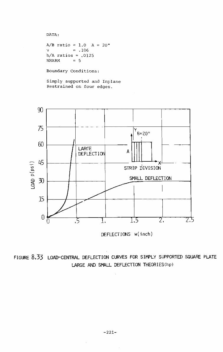
DATA:
A/B ratio =1.0 A V = .316 h/A ratios = .0125 NHARM = 5
= 20"
Boundary Conditions:
Simply supported and Inplane Restrained on four edges.
DEFLECTIONS w(inch)
FIGURE 8.33 LOAD-CENTRAL DEFLECTION CURVES FOR SIMPLY SUPPORTED SQUARE PLATE
LARGE AND SMALL DEFLECTION THEORIES(hp)
-221-

400
~ 300 •H cn ft ft
Q 20 0 •a.
10 0
A A A Finite Strip o Finite Element (8 4)
Y , ( i
2: >-to
"~i—-J
1 A
-Lv ^ — B—*\
STRIPI DIVISION
10 2.0 30
DEFLECTIOK w (inch)
SMALL DEFLECTION THEORY
90.0
75.0
•H IA CL
ft
Q
O 1
60 0
45.0
30.0
15 0
0.
// V 0
/ /
> /Data:
/ same as in Fig. 8.35.
- Finite Finite
1
Strip Element
(8-4)
00
b.
10 20 .30 40 .50
DEFLECTION w(inch)
LARGE DEFLECTION THEORY
60
FIGURE 8.34 LOAD CENTRAL DEFLECTION CURVES FOR MARCAL's S.S. PLATE (cp)
-222-
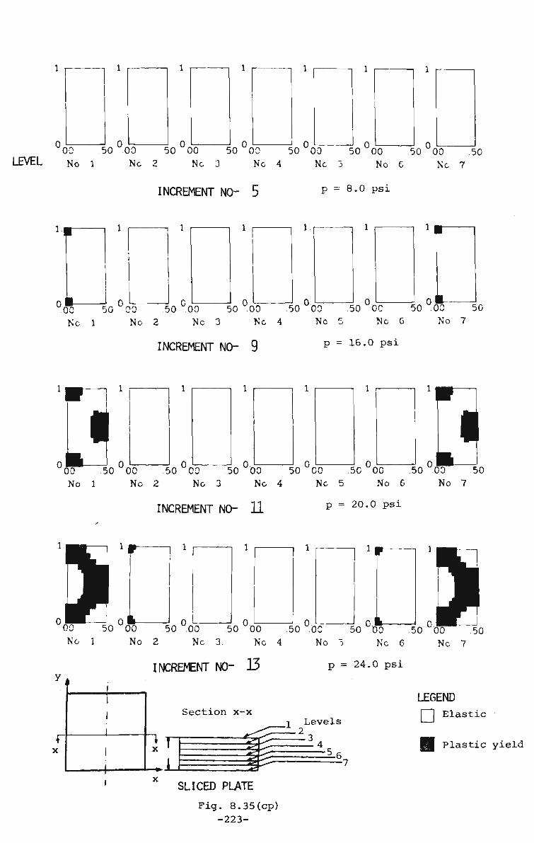
0 0 0 0 0 00 50 00 50 00 50 00 50 "00 50 "00 50 "00 .50 LEVEL No 1 Nc 2 No 3 Nc 4 Nc 3 No e No 7
INCREMENT NO- 5 p = 8.0 psi
0 0 0 0. 00 50 00 50 00 50 00 50 00 50 DC 50 00 50 Nc 1 No 2 Nc 3 Nc 4 Nc 5 Nc 0 No 7
INCREMENT NO- 9 p = 16.0 psi
J 0 0 0.
I 0,
00 50 "00 .50 "00 50 00 50 00 50 00 .50 00 50 No 1 Nc 2 Nc 3 Nc 4 Nc 5 No 6 No 7
INCREMENT NO- U p = 20.0 psi
0 0 0 O.J 00 50 00 50 00 50 00 50 OC 50 00 50 0 0 ^ ~5Q No 1 No 2 Nc 3. Nc 4 No 5 Nc 6 Nc 7.
INCREMENT NO" 33 p = 24.0 psi
Section x-x
X ' IS
I Levels 1-2
=1* 5„
LEGEND f~J Elastic
Plastic yield
SLICED PLATE
Fig. 8.35(cp) -223-

I 00
LEVEL No 1 50 °00 0 50 00 50 "00 50 "00
No 2 No 3 No 4 „ 0 • 50 00 50°00~
INCREMENT NO- 15
No 5. No 6
p = 28.0 psi
No 7
YIELD SEQUENCE IN A SYMMETRICAL HALF OF PLATE AT VARIOUS LEVELS
CO
ft
<
o
40 0
30 0 -
20 0
10 0
.0 10 20 3 0
DEFLECTION W (inch)
LOAD-CENTRAL DEFLECTION CURVE
DATA:
A/B ratio =1. V =.316 h/A ratio =.0125
Initial Increment of Uniform Load NHARM = 5
Y i.
1-STR
i •
C/J
- B — ^
IR DIV
t A
u '*• X
ISI0N
Boundary Condition-:
Simply Supported and Inplane Restrained at the boundaries
FIGURE 8.35 YIELD SEQUENCE AND LOAD-DEFLECTION CURVE FOR MARCAL'S S.S.
PLATE-SMALL DEFLECTION THEORY(cp)
-224-
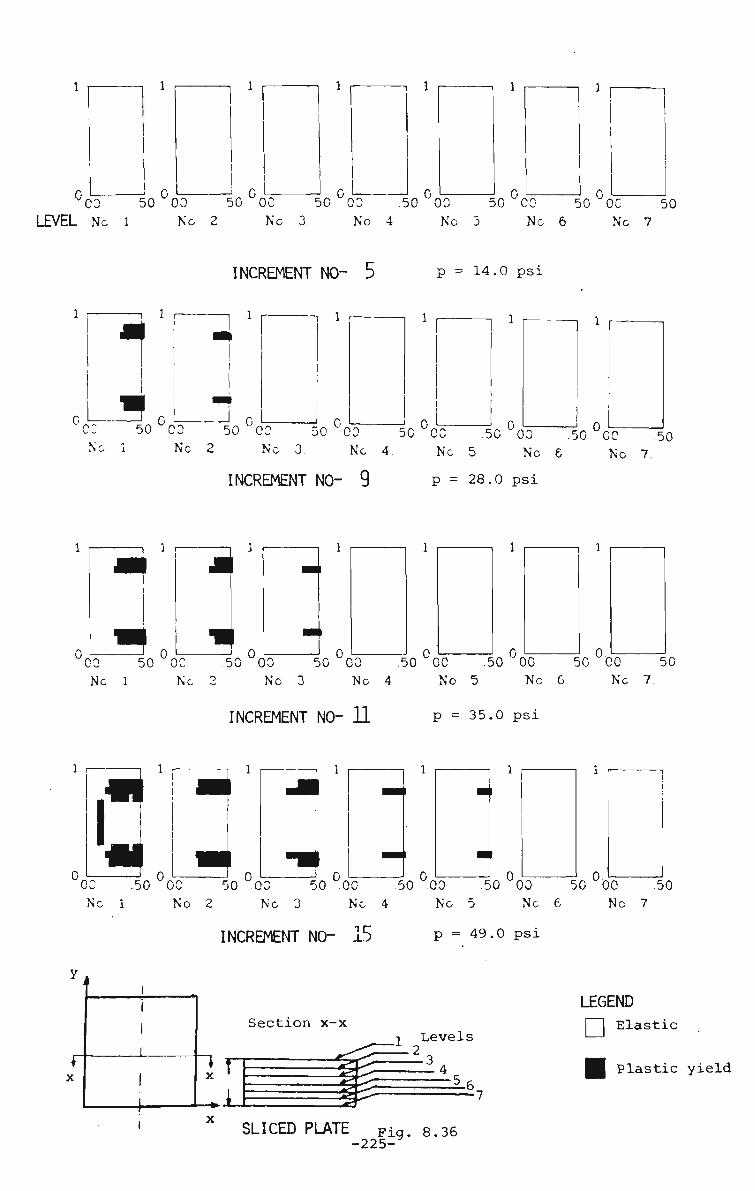
1 1
03 50 00 50 00 50 00 50 00 50 CO 50 00 50 LEVEL Nc 1 Nc 2 Nc 3 No 4 No 5 Nc 6 Nc 7
INCREMENT NO- 5 p = 14.0 psi
1 r
0 L J 0 c: N
50 00 50 CO 50 00 Nc 3. N
INCREMENT NO- 9
o 50 00 .50 "03 .50 "CO .50 1 N c 2 Nc 3. Nc 4 Nc 5 No 6 No 7.
p = 28.0 psi
-| J- f
0 J. 0 0 0 50 0C 50 00 .50 00 .50 00 50 00 50 CO 50
Nc 1 Nc 2 No 3 Nc 4 No 5 Nc G Nc 7.
INCREMENT NO- 11 P = 35.0 psi
1
CO .50 °0C 50 °00 50 °0C 50 "00 50 "00 50 "00 .50 Nc 1 No 2 Nc 3 Nc 4 Nc 5 Nc 6 Nc 7
INCREMENT NO- 15 P = 49.0 psi
Section x-x
32
i Levels
56,
LEGEND [ | Elastic
Plastic yield
SLICED PLATE Fig. 8.36 -225-

0 0 0 0 00 50 00 50 00 50 00 50 00 50 00 50 00 50 LEVEL No 1 Nc 2 No 3 Nc 4 Nc 5 Nc G No 7.
INCREMENT NO- 17 p = 56.0 psi
0 0 00 50 .00 50 00 50 00 50 00 50 00 50 00 50 No 1. Nc 2 Nc 3. Nc 4 No 3. No 6 Nc 7.
INCREMENT NO- 19 p = 63.0 psi
o L-5B 0L——?
i l
o.J 3 =L o
00 50 00 50 00 50 00 50 00 50 00 50 00 50 Nc 1 Nc 2 Nc 3. Nc 4 Nc 5. Nc 6 No 7.
INCREMENT NO- 21 p = 70.0 psi
YIELD SEQUENCE IN A SYMMETRICAL HALF OF PLATE AT VARIOUS LEVELS
900 DATA:
A/B ratio= 1. V = 0.316 h/A ratio =.0125
>-<n
17 A=2Q"
STRIP DIVISION Initial Increment of of Uniform Load p = 3.5 psi NHARM = 5
Boundary Condition:
Simply Supported and Inplane Restrained on Four Edges.
00 10 20 JO 40 50 60
DEFLECTION W (inch) LOAD CENTRAL DEFLECTION CURVE
FIGURE 8.36 YIELD SEQUENCE AND LOAD-DEFLECTION CURVE FOR MARCAL's S.S,
PLATE-LARGE DEFLECTION THEORY^cp) -226-

0 0 'OO 50 OO 50 00 50 00 50 00 50 00 50 00 50 LEVEL No 1 Nc 2 No 3 Nc 4 Nc 5 No 6 No 7
INCREMENT NO- 5 Q = %-• = 6.667 M o
0 0 00 50 00 50 00 50 00 50 00 .50 00 50 00 ^0 No 1 Nc 2 No 3 No 4. No 5 Nc 6 No 7
INCREMENT NO- 7 Q = 10.0
I 0 0 0 0. 0
II 00 50 .00 .50 00 50 00 50 00 .50 00 .50 00 50 No 1 No 2 No 3 Nc 4 No 5 No 6 No 7
INCREMENT NO- 9 Q = 13.333
rO, 0 0. 00 50 00 50 00 50 00 50 .00 50 00 .50 00 .50 No 1 No 2 No 3 No 4 Nc 5 No 6 No 7
INCREMENT NQ 11 Q = 16.667
LEGEND | | Elastic
H Plastic yield
SLICED PLATE F i9- 8.37(cp)
-227-

0 0 00 50 00 50 00 50 00 50 00 50 00 50 00 50
LEVEL No 1 No 2 No 3 No 4 No 5 No 6 No 7
INCREMENT NO- 13 Q = 20.0
0 0 00 50 00 50 00 .50 00 50 00 .50 00 .50 00 50 No 1 No 2 Nc 3 No 4 No 5 No 6 No 7
INCREMENT NO" 15 Q = 23.333
YIELD SEQUENCE IN A SYMMETRICAL HALF OF PLATE AT VARIOUS LEVELS
30 0
25 0
20 0 or
9 15.0 q
10.C
50
0*
/(5)
Increment No- (n) I
DATA:
A/B ratio V h/A ratio
1.0 .316 .20
2: > to
LL1_L J
t A
i, B
STRIP DIVISION Initial Increment of Uniform Load Q
= 1.667 NHARM = 5
Boundary Condition:
Simply Supported and Inplane restrained at the boundaries.
2 DEFLECTION W D/M J\
2.
LOAD-CENTRAL DEFLECTION CURVE
FIGURE 8.37 YIELD SEQUENCE AND LOAD-DEFLECTION CURVE FOR SIMPLY SUPPORTED
SQUARE PLATE(cp)
-228-
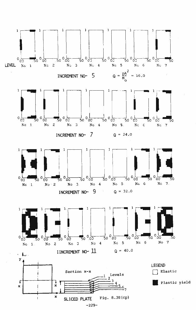
LJ OnV . o.
r
i 00 50 00 .50 CO 50 03 50 03 50 03 50 CO
LEVEL Nc 1 Nc 2 Nc 3 Nc 4 Nc 5 Nc G Nc 7
2 INCREMENT NO- 5 Q = |- = 16.o
o
50
II 0 0 L- JQ,
00 50 00 50 00 50 00 50 "CO 50 "00 50 "00 50 Nc 1 Nc 2 Nc 3 Nc 4 No 5. Nc C Nc 7
INCREMENT NO- 7 Q = 24.0
0 0 0
1 f «•• 1
0 '00 50 CO 50 DC 50 00 50 00 50 00 50 00 50 Nc 1. No 2 No 3 No 4 Nc 5 Nc G Nc 7.
INCREMENT NO- 9 Q = 32.0
II ) 0 0 i l 5 0 0 0 0 l l 5 l 0 0 0 0 % ° 0 0 50 °00 50 °00 50 °00 .50
No 3 Nc 4 Nc 5 Nc 6 No 7 Nc 1 No 2
iw I INCREMENT NO- 11 Q = 40.0
Section x-x _l Levels
LEGEND j ! Elastic
X *
-1 ^2
Plastic yield
SLICED PLATE F i 9- 8.38(cp)
-229-

0 III 00 50 00 50 00 50 00 50 03 50 "03 50 "00 50 LEVEL Nc 1 Nc 2 Nc 3 Nc 4 Nc 5 No G No 7.
INCREMENT NO- 13 Q = 48.0
,H.W.L!I LJ .H.H (00 50 00 50 00 50 00 50 00 50 00 50 00 .50 No 1 Nc 2 Nc 3 Nc 4. No 5 Nc 6 Nc 7.
INCREMENT NO- 15 Q = 56.0
YIELD SEQUENCE IN A SYMMETRICAL HALF OF PLATE AT VARIOUS LEVELS
Y ,
80.0 to
lx
DATA:
A/B ratio = 1. V = .316 h/A ratio = .20 |^_ B_^j
Initial Increment STRIP DIVISION of Uniform Load
Q = 4.0 NHARM = 5
Boundary Condition:
Fully Fixed Plate.
u00 01 02 .03 04 05 06 07 .08
DEFLECTION TVD/MQA
LOAD-CENTRAL DEFLECTION CURVE
FIGURE 8,38 YIELD SEQUENCE AND LOAD DEFLECTION CURVE FOR CLAMPED SQUARE PLATE(cp)
-229a-

Y
4
A .X
i B
STRIP DIVISION
X
M„ = Maximum allowable plastic moment
m 5 M,
FIGURE 8.39 MOMENT PROFILES FOR UNIFORMLY LOADED CLAMPED PLATE
AT YIELD LOAD(hp)
-230-

00 LEVEL No l
l.°oo l.°oo L0£d 1, °0o ±°£-o 1 °£o \ N o 2 No 3 No 4 No 5 No 6 No 7
INCREMENT NO- 5 Q = {j- = 5.333 o
Jl,0 00 lPnn
I 00 -L' 00 l.°ol JL
Nc 1 Nc 2 Nc 3 Nc 4. Nc 5 Nc C Nc 7
INCREMENT NO- 6 Q = 6.667
l-i
i ° f t — J i ° lo,
II lo, 00 -"-"DO x "oo •'•"oo -"-"oo . -*-~oo
No 1 No 2 No 3. No 4 No 5 No 6 No 7.
INCREMENT NO- 7 Q = 8.00
oo -"oo .00 oo oo No 1 No 2 No 3 No 4 No 5 No 6 No 7
INCREMENT NO- 9 Q =s 10.667
Section x-x
IT -1
a 1
_! Levels
" ^4_
LEGEND
| [ Elastic
Plastic yield
S^ SLICED PLATE Fig. 8.40
-231-

00 LEVEL No l
00 No 5
\ °SS No 6
INCREMENT NO- l1 Q = 12.333
YIELD SEQUENCE IN A SYMMETRICAL HALF OF PLATE AT VARIOUS LEVELS
Q < O
15 0
12 0
90
60
30
.0
-
Strip Division b/a Ratio- 2 00
1
y"(9)
/(7)
/ w A3)
1
^UD
—
Y -
i i
£ to
t A
1, DATA:
A/B ratio =' 1.0 V = .316 ^__ B-h/A ratio = .20 STRIFj DIVISION
Initial Increment Uniform Load = Q
= 1.333 NHARM = 5
Boundary Condition:
Simply Supported and Inplane Restrained at the boundaries.
2 DEFLECTION W D/MrtA
LOAD-CENTRAL DEFLECTION CURVE
FIGURE 8-40 YIELD SEQUENCE AND LOAD-DEFLECTION CURVE FOR SIMPLY SUPPORTED RECTANGULAR
PLATE(cp)
-231a-

OA OC 50°00 5O°00 50°00 50 °00 50 °00 50° 50 OC 50
LEVEL Nc 1 No 2 No 3 No 4 No 5. No 6 No 7
INCREMENT NO- 12 0 = 1? -ii.o o
1 r—
II
0
1
0 OC 50 00 50 00 50 00 50 00 50 00 50 00 50 Nc 1 Nc 2 No 3 No 4 No 5 No 6 No 7
INCREMENT NO- 14 Q = 13.0
I 0 0.
i L_ 00 50 00 .50 00 .50 00 50 00 .50 00 50 00 150
No 1 No 2 No 3. No 4 No 5 Nc 6 No 7.
INCREMENT NO- 17 Q = 16.0
II m-00 50 00 50 00 50 °00 .50 00 50 00 50 00 50
No 1 No 2 No 3 No 4 No 5 No 6 No 7
INCREMENT NO- 22 Q = 21.0
Section x-x •i Levels • 2 _
LEGEND 1 j Elastic
IT -1
a Plastic yield
S ^ : s-^"
SLICED PLATE Fig- 4.41(cp)
-232-

LEVEL No l No 2 50 00 50 00 50 00 50
No 3 No 4 No 5 No 6 No 7
INCREMENT NO- 24 Q = 23.0
0 0 00 50 00 50 00 50 00 50 00 50 00 50 00 50 No 1 No 2 Nc 3 No 4 No 5 No 6 No 7
INCREMENT N0~ 26 Q = 25.0
YIELD SEQUENCE IN A SYMMETRICAL HALF OF PLATE AT VARIOUS LEVELS
30 0
Y
Increment No. - (n)
> •
c/> I DATA:
A/B ratio = 1. V = .316 h/A ratio = .20 i B ,
Initial Increment STRIP DIVISION of Uniform Load
Q = 1.0 NHARM = 5
Boundary Condition:
Simply Supported and Inplane Restrained on all Edges.
o DEFLECTION W D / M J T
LOAD CENTRAL DEFLECTION CURVE
P1GURE 8.41 YIELD SEQUENCE AND LOAD-DEFLECTION CURVE FOR A SIMPLY SUPPORTED SQUARE
PLATE WITH REDUCED LOAD INCREMENT SIZBcp)
-232a-

DATA:
A/B ratio v h/A ratio
Q = £^2
Mo NHARM
1.0 . 316 .20
1.667
5
Boundary Conditions:
1-to
T A
a B STRIP DIVISION
Simply supported at the boundaries and inplane restrained.
1 2 3 4 5 6 7 8 9 NUMBER OF STRIPS OVER PLATE
FIGURE 8,42 CONVERGENCE CURVE OF COLLAPSE L0AD(hP)
-233-

CN
o .
CN
-4S
a
§.0 yS
0 §
0
r — — —
P " Y 1
1 ,
1
i
5 t A _
STRIP DIVISION
0. DEFLECTION WD/M Q A
DATA: Same as in Fig. 8.4-2
SIMPLY SUPPORTED PLATE
.2
SYMBOL
•- * — ,,m.
INCREMENT TYPE
ss50
SS40
ss25
ssl5
LOAD STEP SIZE
5.0
4.0
2.5
1.5
COLLAPSE LOAD-Q
23.00
23.66
27.33
27.00
FIGURE 8.43 CONVERGENCE CURVES FOR OPTIMUM INITIAL LOAD
STEP SIZE(hp)
-234-

Y
iinrt 1 V
xPdiilX ZPd) S 0-jO«
NEL(I)|=J
Sfri
!L<I]«^
o NTAPE : 4 E e^
B«
w
= 2
DATA:
Aspect ratio =1.0 V = .316 E = 1.0 h/A ratio = .10 NICR = = 3
A NGX = 5 NGY = 6 Initial Disp. Type = TYY NHARM = 5 c = 8. r = 1.15
1 Boundary Conditions: v = v = w = 9 - 0 . along the boundary
w = w. Sin' ~ Sin o - c- B - :• A
r 2 TTX _ . 9 TTV z — • Sinz - x
B - '•' .. '. A
Uniformly distributed Load
ITYPE = PLATE Tolerance = .05 U.D. Load
FULLY FIXED PLATE IN LARGE DEFLECTION ANALYSIS(BRIDGE PROGRAM)
B ~\
03
u H u CU
•Jl
XS(I) YS(I)
NTAPE
-x-
Uniformly distributed Load
< 1
• . 1
i
NSLICE = 6
T h
1
DATA:
Aspect ratio V = .30 E h/A ratio a N?CR NGX NGY IGTR GTR SENS RTYPE
—
=
= =
=
=
1.0 906200.0 .20 150.0 3 4 6 8 .20 1.75 SMAL
b- FULLY FIXED PLATE IN SMALL DEFLECTION ELASTO-PLASTIC ANALYSIS CPLAST PROGRAM)
FIGURE 8.44 SAMPLE PROBLEMS FOR TESTING THE COMPUTER PROGRAMS(hp)
-235-

.JF"
• ^
vpvpvpvpvovovovovovo
. VO VO
cn ro ro r- r~ r-. r* r» r~
r o v o c o o o v o v o v o v o v o v o I I I l I l I I l I
i n ^ T f ^ T r ^ ^ t i ^ T j i , * i I l I I I I i i c y c u c u _ c u c u c u c u c u c u c u r o m r o r o r ^ r ^ r ^ r - r ^ P o v o i n i n c n c n c n c n c n c n CN ro l
H rH rH H
to
C/3
to
to
rp r o r o r o r o r o r o r o r o r o j I I I I I I I I I oovoro^<oo^^.^.^Ji^
vovovovovovovovo «* »*
fLnmiriinininininin
C N C N C N C N C N C N C N C N C N C N I I I I I I I I
a ) o u q q c u , < u c u c u c u c u ^ C n r H r H r H r H r H r H r H r H
cninvovovovovovovovo c n o o o o o o o o o • • • • • • . . . ,
KO
I l I l I I l I l I
( D C U O C D C U C U C D C D C U C U O OM?) in H H r-l ri rR rl ro in.ro co r r* r» t> r* t ovoinincyicncncncyicn CNnHHHHHrlrlH
3 CO
r O C N r O r O C N C N C N C N C N C N I I I I I I I I I I
cncooorororooororo v o i n m m o o o o o o fOHCJIWHHHHHH
fe O O O 0 0 O O 0 0 O C N " *
cNoo^^rinvoor^r-oo
vp vp VO VO VO VO VO
§&kkkkk •* ** i—I vo r> r~ r-.
c^ r~ en ro rH rH rH ro ro vp op vp vp vp
in in •<* -^ •* T* TJ. ' I i I l i i cu cu cu cu cu cu cu CN VO «* "^ rq rH r^
ro ro in ro r~ r-» r~ o o vo in cn <n cn • • • • • • •
CN CN rO r-l rH rH rH ro ro ro ro ro ro ro
kkkkkkk oo oo •sr «* n< TJ< rj< t f VO VO VO VO VO • • • • • • « * in in in in m
CN CN CN CN CN CN CN I I I I I I I cu cu cu CU CU CU CU r- [ <n rH rH rH rH
cn en in vo vo vo vo CTI cn o o o o o • • • • • • •
^f 'sr r- r~ r» r^ t-•^ <* <• «sr -sj< n< TJI
I I l l l I l cu cu d) cu cu cu cu oo oo in oo r>- r> r> o o vo in cn cn cn • • • • • • •
CN CN OO rH rH rH H
mm. invomvDcnr~vovo
s c N o o ^ ^ m m v o m v o r -
ro ro ro ro fN CN CN I I I I I I I a> d) cu cu cu cu cu O M S r» n r> r r> cn cn oo o ro ro ro vo vo m m o o o • • • • « . .
ro ro rH cn rH rH rH I I
5
§ vpvpvpvpvovovovo
r- t- r^ r-$ c^ c^ <£ eg eg <g • * H H VO [-- cn cn ro • • •
r o v o v o o o v o v o v o v o I I I I I I I I
' I I l l l l T
cucucucucucucucu cgM r o i n i n c o r - r - r ^ r -o v o v o m c n c n c n c n
C N r O r O r H r H H r H r H
r o r p r o o o r o r o r o r o I I I I I I I I Q J C U C U C U C U C U C U C U CDinvOCNCNCNCNCN ^fVOVOVOVOVOVOVO 'tfininininininin
CNCNCNCNCNCNCNCN I I I I I I I I
g & & S J2J S 3 3 OMniilvOvDvOVOVO C T i O O O O O O O • • • • • « • •
o vo m o m o m oo ro «* vo r en o
in vo in in in vo r
CN CN oo f m m m
i I I I I I I T c u d j c u o c u c u c u c u H^OO^FrHrHrHrH rommoot^r^r^r-ovovomcncncncn CN ro 00 rH l
rH rH rH rH
r O C N C N O O C N C N C N C N I I I I I I I I
< u c u c u d ) < U ( u c u c u cnooooorooororo v o m m m o o o o ro I rH rH Cn rH rH rH H
C N 0 0 O O O O O C N ro^vocootN^cn
^ ^ m m m v o r ^ o o
c N r o o o ^ m m m v o
cc c_> C N C N C N C N C N C N C N C N l N C N oo ro oo ro ro oo oo ^J* *3* ^J* ^* ^* *rj< ^j* ^ji
-J O CO H N c n " * "i vor^oocno H CN n \iH in vo r> oocnorHCNro'a,m
rHrHCNCNCNCNCNCN
-236-
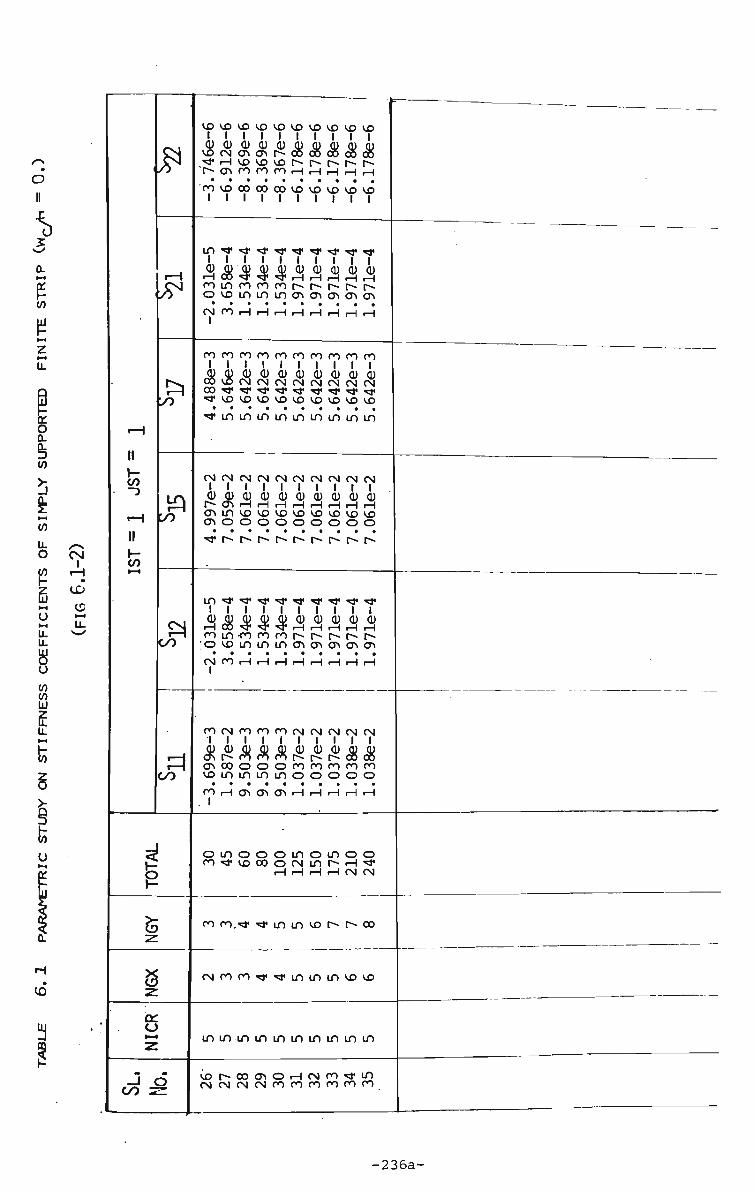
I — 1
II r-C/J
rH
II
£
rH
r^
rQ
r^ OO
rH1
oo
1 (5 z
NGX
a: o •—<
J 6 oo z=
vovovovovovovovovovo
cucucucucucycucucuQ) vocNONONr^ooe5oc»c»e» f H v O V O v O P - M N i v i s T-eSNOOrOrOrHrHrHrHrH "CO VOOOOOOOVOVDVOVOVD 1 1 1 1 1 1 1 1 1 1
Aiiiiiiiiiiiiii o v o m m m o N O N O N O N O N C N C O r H r H r H r H r H r H r H r H
oooooororooororororo 1 1 1 1 1 1 1 1 1 1 djcucucucucucucucucu C O V O C N C N C N C N C N C N C N C N 'd'VOVOVOVOVOVOVOVOVO • • • • • • • • • •
^ m m m m m m m m m
C N C N C N C N C N C N C N C N C N C N 1 1 1 1 1 1 1 1 1 1
cud)cucucucucucucucu |^e£rHH.HHrHHrHrq ONrnvovovovovovovovo O N O O O O O O O O O • • • • • • • • • •
k eg k k k k k k k k ooin-corooor*r~r-r*-r~ .ovommmoNONONONON CSiCnr-ir-ir-ir-it-tr-ir-ir-i
roeNrororocNCNCNeNCN
kkkkkkkkkk ejNOOooorororororo v o m m m m o o o o o
• • • • • • • • • a
OOrHONCneTlrHrHrHrHrH
o m o o o m o m o o ro<*vocooNinr-H^
rH rH rH rH CN CN
ro cn.*r <•# m m vo r» r- co
rNoooo-<r*j«inininvovo
m m m m m m m m m m
V O O - O O O N O r H C N O O ^ f m C N C N C N C N O O O O r O O O O O O O

II r-to -)
II
to l-H
£
rH
rH !/0
rQ ^0
3 oo
r=l OO
1 z
s z O i—i
z J 6 oo sz
kkkkkkkkkk . C N ^ H v o o r o o o r o r o ^CNOOOOrHCNCNCNCNCN i—ICMCNCNCNCNCNCNCNCN
m m v o v o m v o v o v o v D v o l l 1 l 1 1 1 1 1 1 ClJCUCUdjCUQJCUCUCUQJ r H i n o o e n c N ^ v o i n o o c~-eN'*cNr>vomr>r>r> • • • • • • • • . .
m r ^ r o v o r H m o r ^ m m i i i I l l l I
rorooorooooooooororo 1 1 1 1 1 1 1 1 1 l QJCUQJdJQJCUCUCUCUCU r ^ o m o o i n c o r o o o o o o o roinvooo«sj,oovooooooo
fvO^t^vOr^inmr-r" • • • •
oooooO'rj'ro^'Tj'Tf^T}!
eNCNCNCNeNCNCNCNCNCN 1 1 1 1 1 1 1 1 1 1 QJdJd)djd)d>QJQJCUQJ O O O ^ O O ^ o 5 e 3 K r H « » e » t-^oocnooenooorHcoco r o r - r ^ m r ^ m v o v o m m r-\r-ir-ir-ir-\r-\rHr-tr-{r-\ 1 1 1 1 1 1 1 1 1 1
Ln,*^iiin^i^,^"!),^i<* i i i i I i i I i i QJQJCUdjCUCUQJCUCUCU o r o o o c D m r - c N ^ r o o o o ooc3N•om^^,^l,vDvo^J,^J,
i ^ V O O C N r H O O O O O C O r H r H O N r H r H r H r H i H r H 1 1 1 1 1 1 1 1 1 1
rororororororooororo 1 1 1 1 1 1 1 1 1 1 c u c u c u Q j c b c y c u c u c u c u ^rHvor^coeDeJoeocNCN ocNr-"CN<*vocNrnvovo cNrHrHr~Ti«ONOOcncn • • • • • • • • • •
rHmrOCNOOCNrOrOCNCN 1 1 1 1 1 1 1 1 O O O O O O O C O O C N ' ^
( N ( T * ' * i n v O O > h O O
mm, mvomvoesNt^vovo
cNoo^-^cNmvomvor-
CNCNCNCNCNCNCNCNCNCN
HcNrorrmvor-oooNO
1.535e-6 |
1.526e-6
2.331e-6
2.856e-6
2.214e-6
2.204e-6
2.205e-6
-5.823e-5
-5.875e-5
-5.744e-5
5.027e-6
i
-7.089e-6
1
-7.549e-6 j
-7.511e-6
4.257e-3
4.224e-3
4.605e-3
4.598e-3
4.598e-3 !
4.560e-3
4.563e-3
-1.242e-2
-1.245e-2
-1.599e-2
-1.606e-2
-1.606e-2
-1.069e-2
-1.069e-2
-3.483e-5
-3.483e-5
-1.558e-4
-9.349e-5
-1.054e-4
-1.062e-4
-1.062e-4
ro ro ro ro ro ro ro 1 1 1 1 1 1 1 QJ CU QJ QJ QJ QJ CU «* CO O ^ rH 00 r-m m CN r- rH CN CN rH m m r~ o o o • • • • • • •
H H f CN ro oo ro 1 1 1 1 1 o vo m o m o m
ro ro •* vo r~ en o H
m vo m m m vo r
CN CN ro rp m m m
oo co ro ro ro ro ro
H CM ro m vo r> H r-i rH rH rH rH rH
1.529e-6
2.326e-6
2.322e-6
2.848e-6
I
2.205e-6
1
2.205e-6 j
i
5.818e-5
-5.880e-5
I
-5.800e-5
|
4.652e-6
j
-7.504e-6
•
-7.514e-6
:
4.231e-3
4.552e-3
4.570e-3
4.563e-3
4.563e-3
4.563e-3
-1.251e-2
-1.612e-2
-1.602e-2
-1.609e-2
-1.609e-2
-1.069e-2 | 1
-3„484e-5
-1.566e-4
-1.562e-4
-9.377e-5
-1.062e-4
-1.062e-4
1.154e-3
-4.559e-3
-4.540e-3
-2.789e-3
-3.026e-3
-3.027e-3
CN 00 O O O O ro TP vo co o CN
r-i r-i
*t "T m m m vo
CN ro n < j m m
•=* " * •<* ^t* ^ * ^ »
00 ON O rH CN fO rH rH CN CN CN CN
-237-

II I -</)
• ~3
II
1—1
£
rH
r^ y>
rQ y)
3 00
3 00
i z
z
cr 0
z J 6
M 1 =
1
2.205e-6 |
2.202e-6
-7.514e-6
-7.569e-6
4.563e-3
4.563e-3
-1.069e-2
-1.069e-2
1 -1.062e-4
-1.062e-4
-3.027e-3
-3.027e-3
O CN <* en H rH
r- 00
m vo
^ ^ <
««r m CN CN
V p v p v p v O V D V O V O V D V O V O
o o r ^ r H ^ - ^ r o o o o o mroejNOOoocNeNCNCNCN
• • • • • a a a a a
r H C N C N C N C N C N C N C N C N C N
m m v o v o v o v o v o v o v o v o
kkkkkkkkkk O O O O P - O V O r H r H r H V O V O
r - o o o r - ^ m m m m m • • • a a a a a a a
mVOrO^J«T}"r».r>r^.r^r> 1 1 1 1 I | r o r o r o r o p o r o r o r o r o r o
kkkkkkkkkk oororooovDvovovovovo o o r H r H m m m m m m m
• •
ro**^j,«5i<^pr]<'^'^'^|i"?j<
C N C N C N C N C N C N C N C N C N C N
m C N C N O O O O O O O C N V O V O V D V O V D V O V O V O V O r-lrHrHrHrHrHrHrHrHrH I 1 1 1 1 1 1 1 1 1
m^a,mmm, !*^j,^ ,«*'* 1 l l 1 1 1 1 1 1 1 djdjQJQJQJQJQJCUQJQJ V O m C J N m i n C N C N C N C N C N
moO"*f>r^vovDvovovo ^ • i n ^ r o o o o o o o o O O r H c n e j N O N r H r H r H r H r H 1 1 1 1 1 1 1 1 1
oorororororororororo 1 1 1 1 1 1 1 1 1 1 .QJCUCUCUQJQJQJQJQJCU OfOncftffir»M^o5oB ^CJNeJNOOOOCNCNCNCNCN c N m t x r - r - 0 0 0 0 0 • • • • • • • • • • rH'srcNCNCNCOrorororo
1 1 1 1 1 1 1 1 1 o m o o o m o m o o rO«*vOOOOCNinr>H<*
r-i r-i rH r-i CN CN
n n n v m i n v O M ^ o o
cNrorj«'^i'^4inmmvovo
m m m m m m m m m m
v o M X i o i O H N n ^ i n CNCNCNCN ro ro 00 00 00 00
.
—
-237a-

1
rH
II 1 -to
rH II
k
J?
rH
y>
£1 oo
r=.
OO
i 5 z 3 z a: o z
oo -zz
m m m m m m m m m m • i 1 I I i t t I i vooNrocNcNmrnmrom .OOmrHrHrHOOOOOOrOOO mrH'!j,'5l,'*VOVDV0VOVO
• • • • • • * « « a m r ^ m m m m m m m m
•"tfrocooororororororo 1 1 1 1 1 1 1 1 1 l QJQJCUQJQJCUCUCUaJaj r~-vor-»mmc3Ne5NcjNONe3N cNrHencncnrororooooo ONCOCNCNCNOororoooro r-ir-ir-ir-ir-ir-ir-ir-ir-ir-i
CNCNCNCNCNCNCNCNCNCN 1 1 1 1 1 1 1 1 1 1 g £ 8 vg vg rS> r5> g r9> ONONONONONONONONONON
CNCNCNCNCNCNCNCNCNCN
r-ir-ir-ir-ir-ir-ir-ir-ir-ir-i
I 1 1 1 1 1 1 1 1 1 cucucuajdjcucucuQjQj CNC3NONONONONONONONON ONONONONONONONONONON r^ONONONONONONONONON r-ir-ir-ir-ir^r-ir-ir-ir-ir-i
"fcncncncncncncncncn I I l I l l I I l I cud>d>qjc]jQjcuQjQjQj t^vominmenoNeneyiON .CNrHONONONcororocoro ONC0CNCNCN0000000000 rHrHi-trHrHrHrHrHrHrH
C N r H r H r H r H r H r H r H r H r H
O r H e n e n c n o o o o o VOrOrHrHrHCNCNCNCNCN V O H H H H H H H H H
O O O 0 0 O O 0 0 O C N * * C M f l ^ T f i n v O O M ^ C O
r-i
mmmvomvoenr-vovo
cNro^T'^mmvomvor^
CNCNCNCNCNCNCNCNCNCN
rHcNco«<a«invor^oocno
^inirnnininuunm^^
oiiajcucucucucucucljcij exjoooocNCNCNCNininininiS mminHrHrHrHoornrooooo HHH^^-4-^vovOvOVOVO
* * • * . a
r - r - r - m m m m m m m m m
rprorpoorororooorooorooo
&$&kkkkkkkkk oooooocNCNCNCNforororooo r-ir-ir-ir-ir-ir-ir-ir^r-ir-ir-irA
CNCNCNCNCNCNCNCNCNCNCNCN
Q)Q)QJCUCU(UQJQJCUCUaJCU enenenoNcnencncncnencnen
CNCNCNCNCNCNCNCNCNCNCNCN
rHrHr-HrHrHrHrHrHrHrHrHrH
ajQJQJQJQ)QJQ)QJQJQJQJCU
enenencnenencnencnencnen encnoNONONONONcnencncncn ONONenenenenoNenenencnen r H r H r H r H r H r H r H r H r H r H i H r H
rororooooororororooororo 1 1 1 1 1 1 1 1 1 1 1 1 djcudjd)QjQJCUQ)cijajQJCU vovovoininininoNcncnoNON rHrHrHenenoNONrororororo OOOOOOCNCNCNCNrOOOOOOOrO r-ir-ir-ir-ir-ir-ir-ir-ir-ir^r-ir-i
r H r H r H r H r H r H r H r H H r H r H r H
r H r H r H e n o o c n e n o o o o o rOmrOrHrHrHrHCNCNCNCNCN r-ir-ir-ir-ir-ir-ir-ir-ir-ir-ir-ir-i
mrocNOCN"*vomomocN •«j<vor~vor~cocnr-cnocNON
r-i r-i r H
mt-^comvor-oomvor^ooco
rororO'«i,TP^i,"*mmmmoo —
oo rorororororororooorooo
....
H ^ S S r H r H ^ r H ^ C N ^
-238-
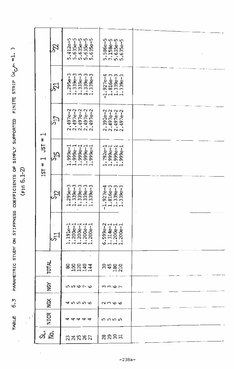
&
m m m m m t I t l I QJ QJ QJ QJ QJ C N m in in in <-i cn cn oo oo •tj* vo vo vo vo
a • • • a
m m m m m
JF
ro ro ro ro ro I I I I I Q) QJ dj QJ QJ in en cn en en O N ro ro oo ro CN ro oo oo oo rlHHrlrl
t>o
CN CN CN CN CN I I I I I QJ CU QJ QJ CU r- r>- r- r-» r~ ON ON ON ON ON *3* ^ ^ "^ ^
a • a a a
CN CN CN CN CN
CO
r-co
i i i i i d) QJ Q) QJ A) ON ON ON ON ON ON ON ON ON ON ON ON ON ON ON
m m m m l i l t cu dj cu cu vo oo m m oo m ro ro m r-i vo vo
a a a a
in r~ in in *r ro ro ro t i l l CU QJ OJ QJ r- vo en ON CN H ro ro ON oo ro ro
CN CN CN CN I I I I QJ QJ QJ r-i r- r-ON ON ON ON CO *tf Tj« «3<
QJ
CN CN CN CN
l i l t QJ QJ QJ QJ CN ON ON ON ON ON ON ON t^ ON ON ON
• • • 9
r-i r-i r-i r-i
ky>
ro oo oo oo oo I I I I I d) d) QJ d) d) m ON. ON ON ON ON 00 CO OO OO CN 00 00 00 00
• 9 • m .
r-i r-i r-i r-i r-i
*& cn cn cn I I I I QJ QJ (U QJ r^ vo cn en C N rH ro ro en co ro ro
r=l OO
I I I I I QJ dj d) cu cu
H O O O O ON o o o o r-i CN CN CN CN
t N H H H t i l l QJ QJ QJ QJ en "* o e5 ON rH o o m ro CN CN
a a a a
VO rH rH rH
o o o o *r oo o CN -*
r-i rH rH r-i
.5 Z
S
m irr vo r~ vo
• m m m vo
^5* ^J' *J* *J* »f
-I o CO z=
o m o o CO ** 00 r-i
r-i CN
ro oo vo r-
CN ro vo vo
m m m m
ro «* m vo r> CN CN CN CN CN
00 ON O rH CN CN CO CO

TABLE 6,4 COMPARISON OF DEFLECTIONS IN SIMPLY SUPPORTED NON-PRISMATIC BEAMS (FIG 6.4)
— ( a t ) —
L/4 L/2
I)
L/4"
Case
1
2
3
4
5
a
.20
.25
.50
.75
1.0
No of Seejments Along
Beam Length
8 16 8
0 - L/4
8
8
8
8
8
L/4~3L/4
16
16
16
16
16
3L/4-L
8
8
8
8
8
Maximum Deflections
Segmented Finite Strij
1*370
1.0690
.5695
.3991
.3124
Conjugate Beam Method
1.3593
1.0967
.5742
.3997
.3124
%
Diff.-
3.21
2.5
.081
.15
0
M
-239-

TABUE 8.1 DEFLECTIONS(w/h) IN CLAMPED PLATES DUE TO
CENTRAL PATCH LOADINGCFIG. 8.12-15)
Patch Size
a=6 = .10
a=3 = .20
a=B = .30
a=6 = 1.0
1 P
P. = ^ ; Eh'
10 20 SO 60 80 100
10 20 40 60 80 100
10 20 40 60 80 100
10 20 40 60 80 100
Central deflection on Thickness (h)
FINITE STRIP
.530 .86 1.28 1.58 1.80 2.0
.508 .79 1.20 1.49 1.70 1.93
.430 .72
1.15 1.40 1.60 1.78
.137
.240
.480
.625
.789
.898
FINITE (1) DIFFERENCE
0.536 0.899 1.360 1.680 1.920 2.150
0.507 0.854 1.280 1.600 1.830 2.030
0.457 0.782 1.200 1.480 1.700 1.890
0.136 0.266 0.491 0.673 0.821 0.946
LINEAR Tirrosh-
enko .605 1.210 2.42 3.63 4.84 6.05
.568 1.136 2.272 3.408 4.544 5.68
.457
.914 1.828 2.742 3.656 4.57
.137
.274
.548
.822 1.096 1.37
-
-240-

ro t-t
>« Z
i—1
»—*
z
<M
r-H
1
r-4
fa
Patch
Size
FINITE
DIFFERENCE
FINITE
STRIP
FINITE
DIFFERENCE
FINITE
STRIP
FINITE
DIFFERENCE
FINITE
STRIP
FINITE
DIFFERENCE
FINITE
STRIP
o
o
o
o
in
in
i
ro
•
CO
+
123)
8.43
< Linear
1-0
in o o o o CA vo n «j m «* ro rH r> oj vo
<-H ro •<* vo r-
O o o m o o • • » • *
in CM CN t 00 o I-H OJ ro co in
VO r-i «* • . a •
CM m oi r~ o oj <-i cn oo CM r~» r-i
rH r-i CN
o o o a . • o o in
r-i o oo o ro in r-i m VO rH rH rH
rH rH
a • o ro o in c as <-i *# r- ON «* VO r-i r-i r-i ri 1 1 1 1 1 1
o m o oj o
>-i o r-i in r~ as "3" r- rH r-i rH ri i i i I i i
ri
r- vo m o o oo r^ ro CM as in <T>
rH CN CN ro ro
in in o in in o t> CM r-i r~ OJ r-
r-i oi oj ro co
o o o o o o r-i OJ ••a1 vo oo o
rH o
00. rH
II II
8
o
O
O
O
m •
i
o <* « i
rH
O
vd
o •
r-
Linear
1.0
OJ
in in m as H m <tf CM 00 OI VO CD
rH CN ** m VO
cn o CM o • b • *
ro rH xtf <tf in r-i OJ ro •* m
o in «* o • • • •
rH o o r-» O CM r-i cn r> o r r>
rH rH r-H
o m o • • co as O f~ CM CN rH ro r-i CM VO ON r4 r-i
o o o o o
in *3* . . . .
a a ro r- in o O O rH •q" r- o *# t-~ r-i r-i rH OI 1 1 1 1 1 1
o in in o • • • • •
o r~ r- vo in o •sT vp o ro in oo 1 T r-i ri ri ri
ON VO
rO r-H r-i in ri <3* If) 01 ^ > O CN
rH rH CN CN
m o o o o o men «* oo <-i cn
rH rH CN CN
o o o o o o H CN ^ VO CO O
cn CN
11 ll"
o
o
o
o
o
o
VO CN
• 1
00
ro «
ro ro •
Linear
1.0
vo CN o m ON OJ VO
f CN CO ro CO H rH OJ «* m [-•
o in in • • • •
«* rH VO O CN CN ri CN "* m VD
r- o o in oo r- vo o o ......
oo ro in TT rH m CN m oo I-H ro
ri r-i
in VD • • CO o
00 OJ 1" O O OJ CM in 00 ri ri
cn CN • . > oo r-» rr
ON ON I-H «d* r— o rO VO ri ri r-i CN 1 1 1 1 1 1
O VTi
• • CN CN in m in vo o ro in r-ro VD r-i ri rH rH 1 1 1 1 1 1
o < n o o o
a t a a •
ON VO O CN 00 CM
ro vo O CN ro in ri ri ri ri
O O O ro O O O
a a a f
in m o in o in ro vo o CN J* in
ri ri r-i ri
O O O O O O ri CN 1" m 00 O
rH
aa ro
II '1*
a
4 1
-241-

T.ABUE 8.3 COMPARISON OF DEFLECTIONS ALONG THE CENTRE LINE (C) SIMPLY SUPPORTED PLATE, CENTRALLY LOADED
STRIP DIVISION.
Ratio of w/w
Load —r = 187 .5 D,h
STATION c/c throucf C.
0
B/8
B/4
3E/8
B/2
5B/8
3B/4
_ 7B/8 B
LINEAR h ANALYSIS
0.
0.28
0.61
0.88
1.0
0.88
0.61
0.28 0
NON-LINEAR ANALYSIS
Finite Element(16
0
0.20
0.47
0.76
1.0
0.76
0.47
0.20 0.
Discrete Element
r—
0
.20
.46
.74
1.0
.74
.46
.20 0.
Finite Strip
0
.21
.48
.765
1.0
.76 5
.48
.21
1
f
• -
•
.. c ?-CO
- |B~J
I A "
J.
-242-
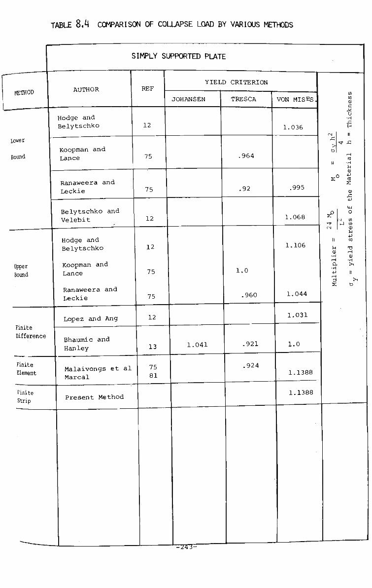
TABLE 8.4 COMPARISON OF COLLAPSE LOAD BY VARIOUS METHODS
METHOD
Lower
Bound
Upper Bound
SIMPLY SUPPORTED PLATE
AUTHOR
Hodge and Belytschko
REF YIELD CRITERION
Finite Difference
Finite Element
Finite Strip
Koopman and
Lance
Ranaweera and
Leckie
Belytschko and Velebit
Hodge and Belytschko
Koopman and
Lance
Ranaweera and Leckie
Lopez and Ang
Bhaumic and
Hanley
Malaivongs et al Marcal
Present Method
12
75
JOHANSEN
75
12
12
75
75
12
13
75 81
TRESCA
.964
.92
1.0
.960
1.041 .921
,924
VON MISES,
1.036
.995
1.068
1.106
1.044
1.031
1.0
1.1388
1.1388
> D
Cfl W CU
c X:
o •H EH
<tf A
-r CN
•H
u CD
s CU
+J
m o
N W •-1 UI
cu u
I CO cu •H
H •H •P H
Tl H CU
•t-i
-24J-"

TABLE 8,5 COMPARISON OP COLLAPSE LOAD BY VARIOUS METHODS
CLAMPED SQUARE PLATE
METHOD
Lower Bouncl
Upper Bound
0) 0
c 0)
Q U 4J CU •H 1-1 C "W •H -H En Q
Finite
Element
Finite
Strip
AUTHOR
Wolfenberger
Ranaweera and Leckie
Koopman and Lance
Hodge and Belytschko
Ranaweera and Leckie
Koopman and Lance
Hodge and Belytschko
Lopez and Ang
Bhaumic and Hanley
Armen et al.
Wegmuller
Present Analysis (4 strips on half plate and 5 (Harmonics)
•
REF
128
75
75
12
75
75
12
12
13
6
128
YIELD CRITERION
JOHANSEN ;
1.560
1.746
TRESCA
1.553
1.596
1.682
1.712
1.56
VON MISES.
1.710
1.786
1.844
2.052
1.901
1.74
2.590
2.22 1.865
2.50
CM X!
>. t>
II 0 s
0 *-i
•sT CN
u cu •rH t-i
cn cn cu X u •H 4-> II
.-I (d •rl VI
£
Si +J
St o H M
3 cn
CO
Tl rH
cu •rl II
(8x8) o^ (12x12) ; Mesh size
•
-244-
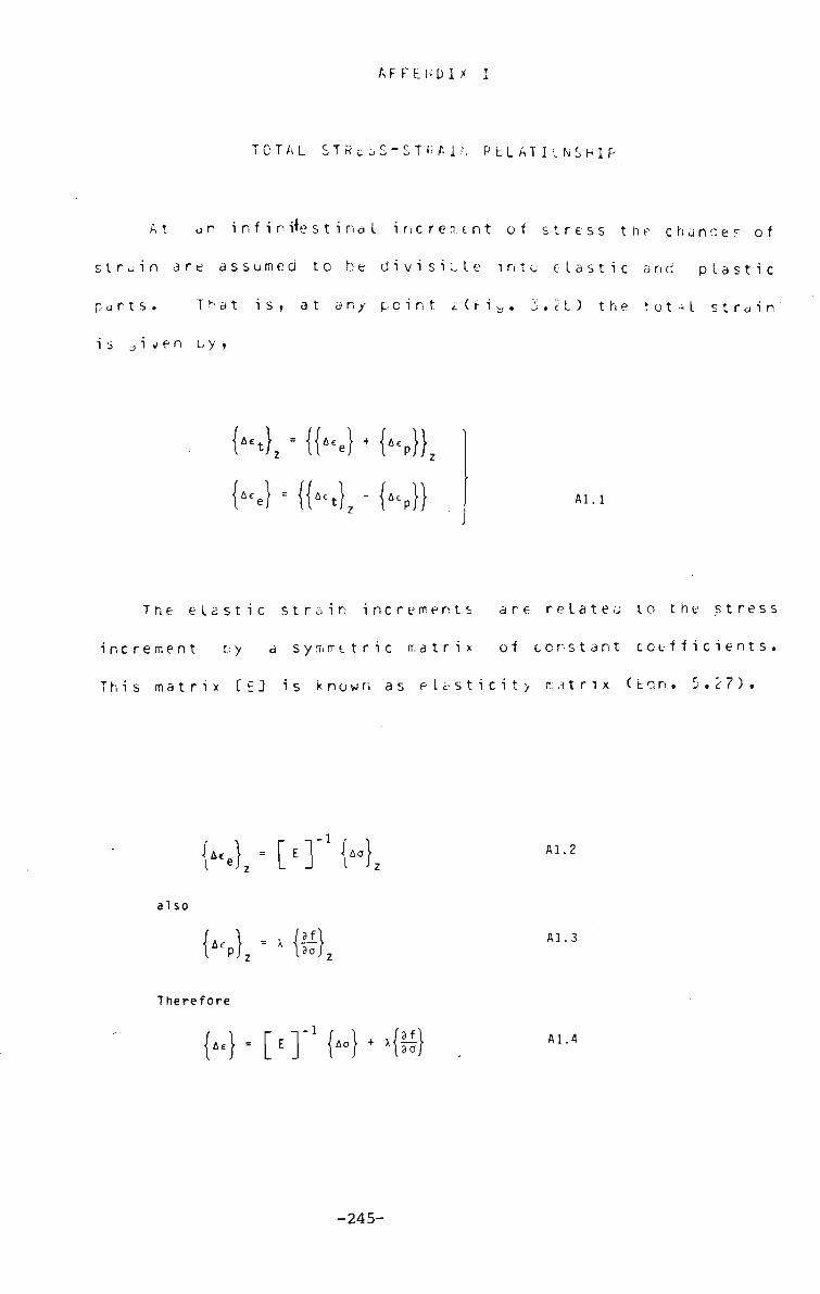
A F F E N D I X I
TOTAL STRci»S-STFiAir, P LI AT I INS H 1 F
At an i n f i n i+e s t i m a I increment of stress the chances of
strain are assumed to be divisible into elastic and plastic
ports. T K a t is. at an/ point /(ti b. 3.11) the tot-l strain
is Jven u y ,
Al.l
The elastic strain increments are relates to the stress
increment t; y a symmetric matrix of constant coefficients.
This matrix [ E J is known as elasticity ratrix (ton. 5,27).
-1
al so
M-['] M
{*«P}, • > m,
A1.2
A1.3
Therefore
M-OT'i-MH} A1.4
-245-

when plastic yielding o c c u r s , the stresses or the yiela
surface are given by,
IR-) • A1.5
here K i s the strain-hardening p a r a i,. e t e r .
;, i 11 e r e n t i 3 t i n g " i ' with respect to e a c h c * the stress
resultants etc., we get,
0 = T Ao. + + -r— d< 3c, 1 Sop 3K
= {^7/ { Ao) + AX
A = T — OK T-3K A
A1.6
EHr,s. M . S arc M . 6 .nay be written ir a sin-jle symmetric
atrix as -follows,
if.
Ae.
[E] -1
3f_
_3o1
3f 3o,
3f 3o,
3f 3o,
Ao.
Ao,
A1.7
-246-

This form is convenient for direct use provided that 'A'
is not equal to zero. Alternatively \ can be
eliminated (taking care not to multiply or uiv/ide Oy 'A'
which may be zero in some cases). This rpsults in an
explicit expression relating the stress chances to the
imposed strain variations.
R/ equation A.Z1 we get,
E*(a) A1.8
Hcre CE*(*T )] . is the "tangential elasto-plastic mooular
Matrix' which is a function of the current stress level and
is Jven oy ,
E*(c) ]['
•]-{u}{ur
EI] - l L"a][E]
A1.9
In cases where strain hardening is neglected,
equa Is to zero
-247-

A. Determination of X in Volume Theo ry
For plastic flow to remain on yield surface,
or
6f = 0
m" -) = o From equation 4.19
ALIO
X is a positive scalar quantity.
Fro* Eqn. 4,2.2 we may write the following expressions
AN
AM
h/2
h/2
h/2
h/2
{"}
:{„,}
dz
dz
Al .11
From Eqn. 4.20
H - [E]{uet^ -<*«P>}, Al .12
or
M .[.]{...,»-{S}J A1.13
-248-
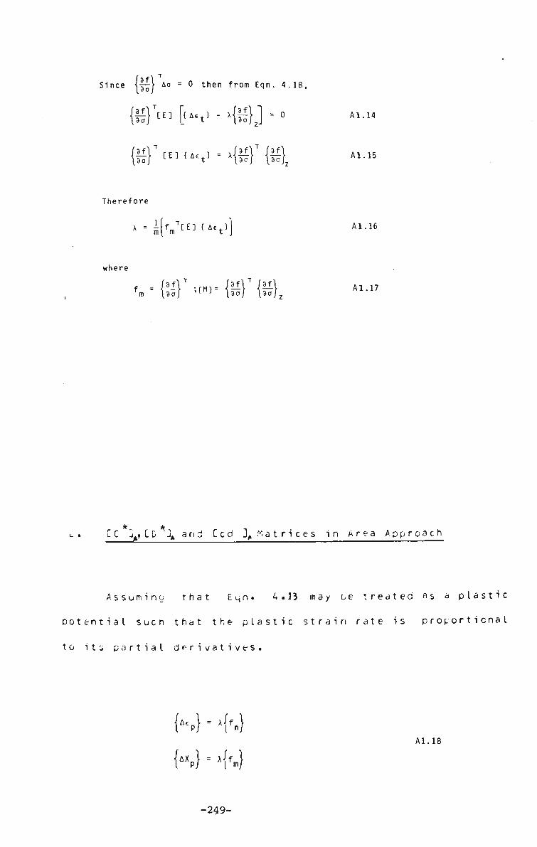
Since {||j Ao = 0 then from Eqn. 4.18,
&}T[E] [u«t> - x{|I}j . 0 A1.14
Al .15
Therefore
* = iK T [ E ] { A £ t } ) A1.16
where
m1 — {§r ®.. A1.17
[C 3t,[D Jt anj Ccd 3, Matrices in Area Approach
Assuming that Eqn. 4.13. may be treated as a plastic
potential such that the plastic strain rate is proportional
to its partial derivatives.
K} • >W Al. 18
-249-

where X is a r o s i t i v e s c a l a r . The elastic incremental
Generalised stress-strain laws are assumed to u e H o o k P a r- in
n a t o r e ('J 7 ) .
H = h[n(K}-K}}
{AM} = fc [E] {JAXt} - JAXp}} Al. 19
S u b s t i t u t i n g into E q n . A1 .19 from Eqn.. A 1 . 1 c and making
use of Eqn. 4.34 gives the following expression for the
plastic strain rate multiplier X is given as,
x = 7^7ry^{fn}TcE]{A£t} + ^ { f m }
T[ E ] ( A X t }
where n = hjfl FED jfl
m " T7 {fm}^E^ {fm} A1.20
TFe plastic strain increments ray be relatec to the
total strain increments uy substitutions from Eon. Al.ZG
into ton. A 1 . 1b .
K } - T i ^ T {«N3[E]{Act} * £ [NM][E]{AXt}}
K} = TiTTTT {hCNM]T [E] K} + IT CM]CE]{AXt}}
-250-
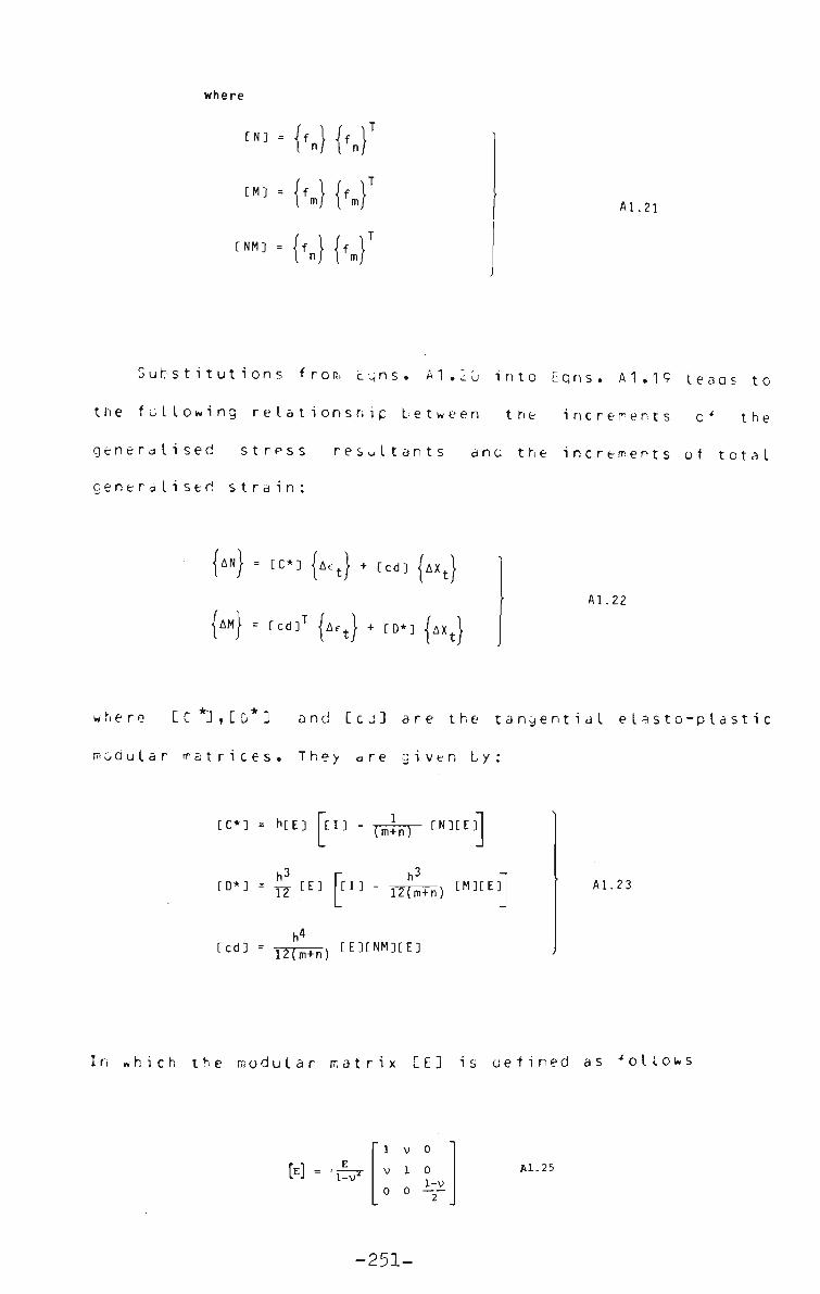
where
[NM]
" • {'-} {'.}T A1.21
Substitutions from e q n s . A1 . 1 u into Eqns. A1.19 leaas to
the fallowing relationship between trie increments of the
generalised stress resultants ano the increments of total
Generalised strain:
{AN} = re*] {A^} + [cd] {AXJ
{AM} = [cd]T {A^} + [D*] {AXt}
A1.22
where CC*"J,CD 3 and C c J 3 are the tangential elasto-plastic
modular matrices. They are given by:
[C*] • h t E 3 C I ] " TmTnT rN][
h3 r h-• T2 I " | m - T2Tiim
3 [ m - TTfi+n) [M][E]]
^ d ] = .)).,,> CE][NM][E] 1Z(m+n;
A1.23
I r. which the modular matrix CE ] is defined as follows
w l-v'
1 V 0
1 0 Al.25
-251-
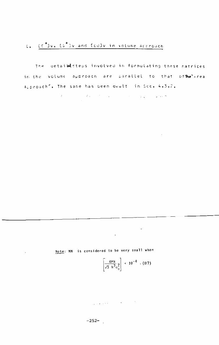
* * -, r
C. LC ]v, Lb ^v and IcuJv in volume Accroach
The uetaiM^teps involved in formulating these matrices
in the volume approach are parallel to that of 1h«"^rea
Approach". The same has been acalt in Sec. 4.3.?.
^ote: MN is considered to be very small when
4MN /3 >J?0
< 10~* .(87)
-252-
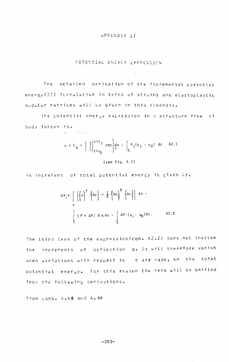
APPENDIX II
POTENTIAL ENERGY EXPRESSION
The Detailed Derivation of the incremental potential
energy(3 3) formulation in terms of strains ana elastoplastic
modular matrices will be given in this Appendix.
The potential energy expression in a structure free of
body forces is,
* = C Q +
E = E. ads dv P 1 ( q 1 - q Q ) dS A2.1
(see Fig. 5.1)
• n increment of total potential energy is given by
i [ (HT M * * M T {' AeH dv
( P + AP) A q ds AP (gx- q^ds. A2.2
The thirc term of the expressicn(Eqn. A2.2) does not involve
the increments of deflection q. It will therefore vanish
when variations with respect to q are made, on the total
potential energy. For this reason the term will be omitted
from the following derivations.
From eqns. 4.49 and 4,50
-253-

M-N*M + [TS] Ax A2.3
On s u b s t i t u t i o n in E q n . A c • T: ,
An = At^V dv +
UJ
0} jAe )• dv +
(2)
1
1 Ao J A E } dv - f (P + AP) Aq ds.
(3) (4)
A2.4
The second term of Eqn. A2.2. may be written as,
1 1 AS AS dA ,
The detailed s t e p s are s h o w n b e l o w .
o\ M £T Ldv =
3Awl . 3x J
'3Aw}'
ay J 3Aw 3Aw 3x 3y
dv:
1 1 [Nx.Ny.Nxy] m
f3Awl2
13yJ ?3Aw 3Aw 3x 3y
dA
*i-[3Aw' 3X
3Aw 3y
,
T
fNx Nxyl . [Nxy Ny J
'3Aw 3x
3Aw 3y
dA
AS T r-
ASy dA
A2.5
A2.6
~ :., n • kl,1 r a y n o w be w r i t t e n »s
-254-

AT, Itt' AE.V dv + fM AS} dA
1
1 Aa} JAE dv
[N]
(P + AP) Ap ds A2.7
A aetailed oerivation of each term will be performed
seperately
TERM - 1(T,1 1'
f HT H dv From equation 4.SO
w = AE + CTS] ASV + z A2.8
On substitution in TERM 1, we have,
Tl = B T (i Ae + CTS] AS • + z-\ -
AX dz dA
A E ^ + CTS] M S + \v\ AX dA
TERM - 2A (T2)
r - l r2 1
AS CN] AS dA
A2.9
A2.10
TERM - 3 (T3)
1
7
T3 = 1
Ae} dv from equation 4.4.{
z f H I Ao} UM\ + {Ae+} + CTS] {AS} + Uo\ -Z-{Ax}}
dz
\ JAN} JAi + Ae+ + [TS] {As}}+| {AM} {Ax
dA
TERM - 4 (T4)
(P + AP) Ap ds.
-255-

T h e i n c r e m e n t a l s t r e s s - s t r a i n l o w is c y i v c n L y ,
CC*] Ae AN
AM} = Ccd] •
+ Ccd] AXi
AeJ + CD*] JAXt} A2.12
Ac, • = Total increment of strain at mid-surface (z=0)
AX< Total increment of curvature.
The above procedure is callec the tangential approach as it
deals with total strains anJ curvatures.
Subscripts A and V stanu for area ana volume approaches
respectively.
From Lon. L.ZH,
Ac •) - H * CTS] MS !• + A E A2.13
Substituting E q n s . 4..37 (are a) 4. 2.9 (volume) and «*.4 6 in the
t e r m s Tj. , T2 a , T^ a n u T3a above we get the following
expressions.
TERM - 1 (no change)
\ {JAE} + CTS] {AS}} + • M| |AX} dA A2.14
-256-
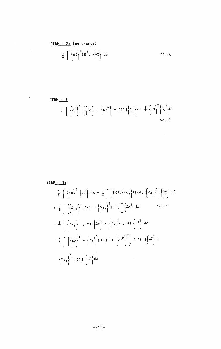
TERM - 2a (no change)
1
1 AS} CN+] MS} dA A2.15
TERM - 3
1 7
ANl Aii + Ae + CTS] AS } * * M T AX dA
A2.16
TERM - 3a
J J {*,}' |.c| dA - \\ [C*] ('
1
7
1
7
1
7
Ac, CC*] + M x + } Ccd]
AcJ+Ecd] |AXt
AE} dA
AE} dA
A2.17
d] ME} dA { A E J cc*] {AE} + {AX4.} CCC
TCTS]T + {AE+} 1 * CC*]|Ai| + AE} +
• AXt} Ccd] {AE}dA
-257-
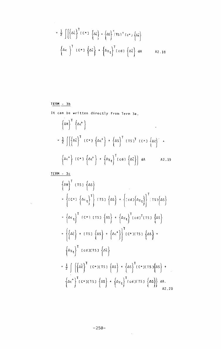
1
7 I J CC*] k} +JAs}Wrc*jk\
Ae } CC*] ME} + • AX1 Ccd] ME} dA A2.18
TERM - 3b
It can be written directly from Term 3a,
T AN AeT
1
7 Ae+ \ + -JAsi CTS]T CC*] MEV {AE} CC*
AE+} CC*] {AE+} + {AXI} Ccd] {AE dA A2.19
TERM - 3c
{AN CTS] * MS •
[C*] M e t } } CTS] M S
= M e t CC*] CTS]
AE
AX<
+ CTS]
AS} + M X t
T
AS} + M E T } } CC*]CTS]
Ccd]|AXt}[ CTS]JAs}
Ccd]TETS] {AS}
Ccd]CTS] Ai
1 7
AE
Ae CC*]CTS]
• CC*]CTS] {AS} + {AS} CC*]CTS]{AS} +
)} Asf + 1AX+r Ccd]CTS] jAS}} dA. A2.20
-258-
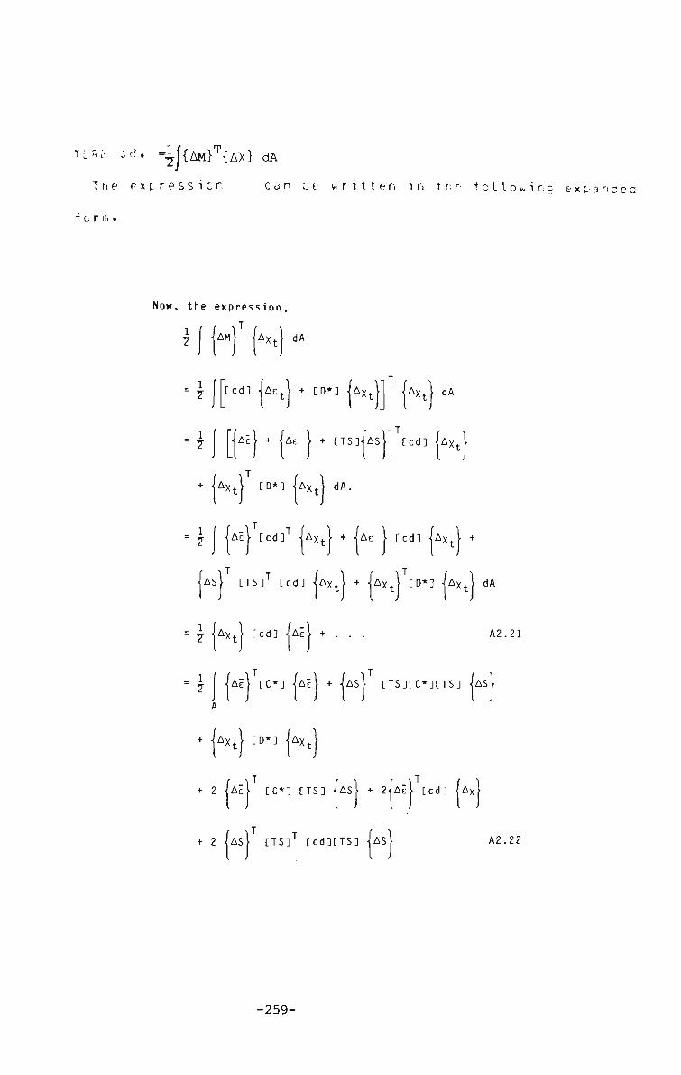
TLM-' id. =1|{AM}T{AX> dA
The expression can ue written in the following ex pa need
•for m •
Now, the expression,
1 7
AM} i
1 7
1 7
Ax<
Ccd] M E
dA
->T + CD*] jAXt
{AE} + {A£ } + CTS]{AS}
AX, dA
Ccd] M X t
AXt} CD*] M x
1 7
r r •>
AE
dA.
Ccd]' M X t + M e Ccd] AX. +
{AS} CTS]T Ccd] {AXt} + {AXt} [D*] {AXt
= { A XJ [cd] AE
dA
A2.21
= \ [ {AE} CC*] {AE} + A
+ {Axt} [D*3 (AxtJ
AS CTS]CC*]CTS] M
r 2 MEi CC*] [TS] (AS} + 2|AE1 Ccd] M x
+ 2 MS} CTS]1 Ccd]CTS] • AS A2.22
-259-

The terms which contain multiplication a re neglected as they
are of higher order, then:
All - T e r m 1 . + Tern c • + Tern 3 . + Term 4.
1 7
cc*] ME} + Ms} CTS]' cc*] Ms} + {AE
A
{AxJ CD*] Ux\ + 2{AE}
AE} Ccd] Mxt[ + 2
CC*][TS] MS} +
T
{N} •{AE} +
AS} CTS]'Ccd]-
T
AX,
CTS] AS + ^M Ax
dA
dA
((j + AU)Au + (V + AV)Av
{AS]V] AS dS
(W + AW) Aw dA
A2.23
-260-
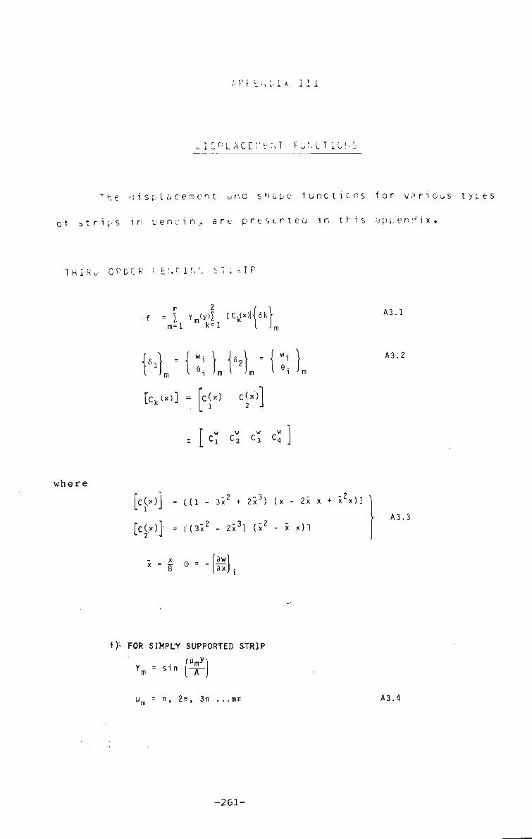
/iPF-EM, I A 111
I 2 PL A C E ? - E M F uM.Tiu!»S
T h e d i s p l a c e m e n t a n d s h a p e f u n c t i o n s f o r v a r i o u s t y p e s
of strips in oencin^ art presenteu in this appendix.
T H I R „• C P D E R F.- E \ C 1 f. C S T . K I P
m=1 k-1
{^ • 1 ;m
[ck<*>]
Wi 1 N = ei Jm I
jm
= fc(x) C(x)j w w w w : I Cj C 2 C 3 C 4
A3.1
A3.2
where
[cOOJ = C(l - 3x2 + 2x3) (x - 2x x + x2x)] '
[cOO]: = C(3x2 - 2x3) (x2 - x x)] A3.3
x _ _ |3w x = B e " _ 3*
i)'- FOR SIMPLY SUPPORTED ST.RJ.P
Um = TT, 2TT, 3TT . . .nm A3.4
-261-

1 i) FOR. FIXED ENDED STRIP
si n ru v
si -m cos nr
«• • s 1 n " • » " s i n h " -
cos p m - cosh Vm
ym = 4.7300, 7.8532, 10.9960...
) - <-(¥)]
A3.5
uf t e n Um for the case of a fixec strip, is
appro*imatea(Z7) as (Zm+1)/2 ,which is not correct and
results in unsyrr. metrical ois placements and stresses at the
symmetrical points when the loaoing ano the structure are
Symmetrical.
The strips having end conditions different from those
given (i) and (ii) above, can easily be incorporated in the
present formulation if desirec. For details of fm functions
related to other types of finite strips (Free-Free,
Fixed-Free etc) appropriate texts may be consulteu(c7).
-262-

A P P E N D I X IV
COMPUTER PROGRAMS
IV.1 General Remarks
The numerical solution of large deflection elastic and
elastoplastic analysis of plates ana multiplate systems ano
the graphical display ot the results have been accomplished
on a UNIVAC 11U6 Computer ana on Textronics 4U25 systems.
The computer programs have been written in FORTRAN V and a
detailed description of these programs including the input
instructions and flow-charts will be provided. Two sets ot
computer programs are developed for both elastic and
elasto-plastic analysis. The first set performs the finite
strip analysis and the second set plots the results obtained
from the first. The programs are:
o BRIDGE Program for large deflection elastic analysis ot
plates and multiplate systems.
o PLAST Program for large and small deflection
elasto-plastic analysis of plates.
The common feature of the above two programs are as
follows. The solution of stiffness equations(Eqns. 3.56 and
5.2b) is accomplished by Gaussian elimination procedurelt'/).
Since the structural or global stiffness matrices are
symmetric, banded and positive definite, they are stored in
-263-
distorted half band width in order to
requirements. The stiffness equations
reauce storage
are non-linear,
therefore i n c r e m e n t a l and also combined incremental ano
iterative(step iteration) method have been adopted. it may
also be emphasised here that the non-linear strio stiffness
matrices(Eqns. 3.56,5.^:5) are coupled with rebara to the
harmonics, therefore we have to consider the contributions
of all harmonics in a stiffness matrix. The band width ot
structural stiffness matrices will be **m" times creater than
that expected in the conventional tinite strip procedure.
VI. I Program Specifications
The p r o g r a m s are w r i t t e n in such a manner that the input
data required to run the programs are very small. The
geometry ana elastic and geometric properties ot the strips
need to be definea. The individual types ot loading(UD,
patch or concentrated) are to be specified. The loading
types are flagged appropriately. The strip number where the
luau i 5. acting has to be provided. The boundary condition
type ranging from fixed to free (excluding partially
restrained section) can be imposed on a nodal line. The
available boundary conditions at the transverse edges are
simply supported or fixed, tor bending, and in the inplane
situation both x and y or only x movement may be restrained.
The "BRIDGE' Program has options for both incremental
and step iteration. The step iteration only can be used tor
initially perfect structures. The "PLAST' Program is based
on incremental approach. The number of increments and also
-264-
the target load have to be s p e c i f i e d . If varying increment
sizes are used the ratio ot two consecutive load increments
should be given as input data. The results for deflection
and stresses for all required points in their absolute ana
non-dimensionalised form will be obtained in the output in
tabular form and also may be stored in a tile tor future use
in plott ing.
The numerical integration procedure used to integrate
the strip stiffness matrix requires the segmentation of the
finite strip. Therefore the number ot subdivisions and also
Gauss points in x and y directions, are to be provided. It
a plate structure has an initial out of plane imperfection,
the ratio of its maximum value to the plate thickness is
given in the input oata. In the fixed plate situation trie
type ot initial imperfection e.g. YKC or TYYlSec. 6.3.4) is
to ue speci tied.
Iv.3 Summary of Computer Programs
A. BRIDGE PROGRAM
The nonlinear elastic analysis ot
structures are performed by this prog
stiffness matrix is defined by Eqn. 3
solved tor various loading condition
uniformly distributed load, patch load a
cases can also be dealt with. The re
and stresses are stored in data-base til
plates and plated
ram. The structural
.56 is formed ana
s. The t ransverse
nd concentrated load
suits for deflection
es tor future use in
-265-

plotiing ana detailed stress o u t p u t s . plot p a c k a g e s .
The major steps involve:
o Read in dimensions of the structure and strip
geometry and properties.
o Define initial geometric imperfections and its type
o Convert it into ** .. ,0 ..,-w . $" 6 by substituting Cl Cl cj cj
co-ordinates in Eqn. 6.6.
o Read loading types and details
o Form matrix L^o^ I Eqn. 3.53), linear stiffness
matrix for each strip ana store in a temporary file
for future use within the program.
o Form [Kn£. j" matrix(Eqn.3.54)
o Assemble the structural stiffness matrix (Eqn. 3.55)
as follows
[KimJ M = M (A4.1)
where,
[KiJ = W + [Kj (A4.2)
o Solve Eqn. A4.1 tor incremental deflections iq> by
Gaussian elimination scheme.
o Add this new incremental displacement to the total
displacement <q> and convert <q> to the nodal line
displacements of the tinite strips.
-266-

If i n c r e m e n t a l p r o c e d u r e is a d o p t e d , then form LKn^.J
again and apply load increment and proceed as
b e t o r e •
If step iteration is adopted residual loaa is
calculated and iteration (eye le ) is performeo within
a load step until a convergence criteria is
satisfied. The convergence criteria in this case is
the ratio of the maximum incremental displacement in
a cycle to that of uptodate maximum total
displacement should be less than O.U05(.5%).
Print u,v,w,6 ana stresses ana store the results in
a data-base tile.
Apply load increment and follow the above steps.
LARGE D E F L E C T I O N P L O T T I N G PROGRAM
Read the s t r e s s e s and d e f l e c t i o n s stored in a d a t a - b a s e
file. A program called "GRAPHIC, has been created to plot
the Load/ Deflection and Load/Stress Curves using the plot
packages available on UNIVAC 11U6 Computer.
-267-

c. PLAST PROGRAM
The e l a s t o p l a s t i c s t i f f n e s s matrix definea by Eqn. A.66
i^ solved by an incremental technique as in the BRIDGE
Program. The transverse uniformly distributed load is
considered. The results tor oeflections and yield
propagation characteristics at various load stages are
stored in data-base. The stored data are post- processec by
a plot program which is designed to produce continuous yield
mapping at various load stages and load/ deflection
response .
r Read in the dimensions of the structure and strip
geometry and properties.
o Define loading type and details.
Form matrix CKEJ as in E o n . 4.65. The sub-matrix
[kio3 ir a null matrix until the structure(plate)
yields.
Solve e q u a t i o n 4.64 by G a u s s i a n e l i m i n a t i o n m e t h o d .
Store the deflections and stresses in data-base file
tor all Gauss points.
Check for Yield c o n d i t i o n . It a point yields its
geometric position is designated by a special
character • and stored. The elastic regions will
remain blank.
-268
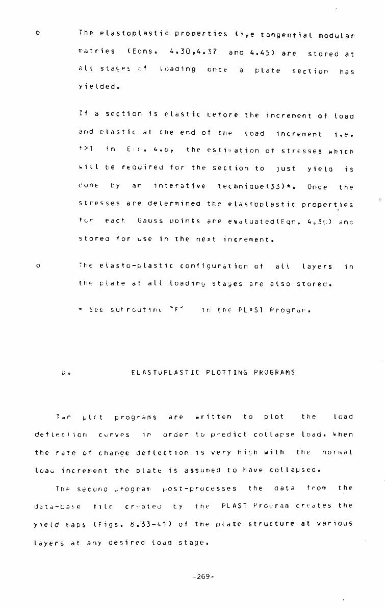
The e l a s t o p l a s t i c p r o p e r t i e s (i,e t a n g e n t i a l m o d u l a r
matries (Eqns. 4.30,4.37 and 4.45) are stored at
all states ot loaaing once a plate section has
yie Ided.
If a section is elastic before the increment of load
and plastic at the end of the load increment i.e.
t>1 in E<n. 4.o, the estimation ot stresses which
will be required for the section to just yiela is
Cone by an interative techniaue(33)*. Once the
stresses are determined the elastoplastic properties
tor each Gauss points are ewa luated(Eqn. 4.3() ano
storea for use in the next increment.
The elasto-plastic configuration ot all layers in
the plate at all loadiny stages are also stored.
* See s u r r o u t i n t F in t h e P L o S1 P r o g r a i>
E L A S T O P L A S T I C P L O T T I N G P R O G R A M S
T-o plct p r o g r a m s are w r i t t e n to plot the load
deflection curves in order to predict collapse load. When
the rate ot change deflection is very hich with the normal
loau increment the plate is assumed to have collapsed.
The second program ^ost-processes the aata from the
data-ba^e tile created by the PLAST Proeram creates the
yield maps (Figs, o,33-41) of the plate structure at various
layers at any desired load stage.
-269-

The t a s k s p e r f o r m e d oy t h i s p r o g r a m a r e :
o Draw the plan view of the s y m m e t r i c a l halt ot d plate
o The y i e l d e d p a r t ( p o i n t s ) of each layer are indicated
by a black square.
u Sketch the strip division ano divide the depth of the
plate into layers.
o Plots the load deflection curves for the structure
The plot is c o n t i n u o u s and the p r o g r e s s i v e yielding may
be videotaped. When the elasto-plastic map is completed for
a particular load stage, a hard copy may be taken or the
whole plot output may be sent to a Calcomp Plotter tor
producing presentable plots(Figs. b,33-41).
r-270-
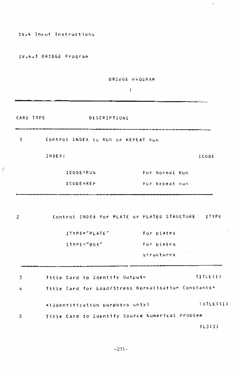
IV.4 Input I n s t r u c t i o n s
IV.4.1 BRIDGE Program
BRIDGE PROGRAM
I
CARD TYPE D E S C R I P T I O N S
Control INDEX to RUN or REPEAT Run
INDEX: ICODE
IC0DE=RUN For Normal Run
ICODE=REP For Repeat Run
Control INDEX for PLATE or PLATED STRUCTURE ITYPE
ITYPE='PLATE' For plates
ITYPE='BOX' For plateO
structures
3 Title Card to Identify O u t p u t - TITLE(I)
4 Title Card for Load/Stress Normalisation Constants*
•(Identification purposes only) TITLE1(I)
5 Title Card to Identity Source Numerical Problem
TL3(I)
-271-

Total Number ot T e r m s -
Total Number of S t r i p s -
Total Number ot Nodal Lines-
Number of Degrees ot Freedom-
(per noda I I i ne)
Length ot Structures- A
Breadth of Structure- BW*
*for plated structure this data is never used
in the program.
NHARM<*
(non-ze ro)
NELEM(<6)
NP
NDF<37
Total Number ot Incremental Steps- ITR<21
INDEX- IREST
IREST = 0 In-plane v Displacement Unrestrained
IREST = 1 In-plane v Displacement Restrained
Ratio ot Two C o n s e c u t i v e Loaa
Increment s ZC
X-Coord of Nodal Lines
Z-Coord ot Nodal Lines
xp
ZP
*See Fig.8.44 a.
Strip Numbe r-
Lett Node Number of Strip-
Right Node Number of Strip-
Thi ckness of St rip-
rVUM
N0D(I ,1)
N0D(I,2)
T(I)
-272-

Modulus of E l a s t i c i t y in X-
Modulus of Elasticity in Y
Poisson's Ratio in X-
Poisson's Ratio in Y-
Shear Modulus-
El
E2
PX
PY
G
•Orthotropic material property can be used
tor the linear elastic analysis only.
INDEX- FORCE
FORCE=0 For U . D . Load
F0RCE=1 For Concentrated Load Case
10 Length Segments in Strip-
Number of Segments in Strips
AICR
NIC*
•Normalised C o - o r d i n a t e s :
Y-Coord of Strip Lett fcdge-
X-Coord of Strip Lett Edge-
Y-Coord of Strip Right Edbe-
X-Coord ot Strip Right Edye
A1
B1
A2
El
Number of X Gauss Points in a Segment
Number of Y Gauss Points in a Segment
N6X
NGY
•See Fig. 8.44a
Unit Number to Store Results-
Unit Number to Store Load/Stress Table
Increment in Harmonics-
ITAPE
ITAPE
NICH
-273-

NICH - 2 for symmetrical case only, otherwise =1
Unit names to store output- Load/Stresses NAME
Unit name to store results i,e Load/Deflections
and Load/Stresses at any intermediate Tiu
load stage
INDEX- 1 F I X
IFIX=0 Simply Supported
IFIX = 1 Fixed L «i R and Simply Supported
Opposite Ends.
IFIX=2 Fully Fixeo Plate
13 Initial Deflection Wc
14 Number of Stress p o i n t s - NSTES
Point(NSTES) from which stresses are storea- NTAPE
••Skip if ITYPE EG "BOX'
15 Coord of right node of strips- BS(I)
16 Global C o o r d i n a t e s ot stress p o i n t s :
X-Coord-
Y-Coord-
XS(I)
YS (I)
-274-
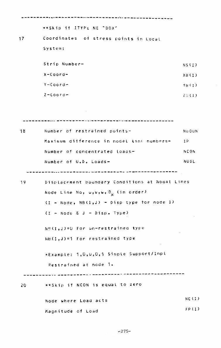
17
••Skip it ITYPt NE "BOX'
Coordinates of stress points in Local
System:
Strip Number-
X-Coord-
Y-Coord-
Z-Coord-
NSII)
XB(I)
YB(1)
2 b t I)
18 Number of restrained points- N60UN
Maximum difference in nodal lint numbers- IP
Number of concentrated loaos- NCON
Number ot U.D. Loads- NUDL
19 Displacement Boundary Conditions at Nooal Lines
Node Line No, u,v,w,'0. (in order)
(I - Node, NB(I,J) - Disp type for node 1)
(I - Node 8 J - Disp. Type)
NP(I,J)=U For un-restraineo type
NB(I,J)=1 For restrained type
• Example: 1,0,1),0,1 Simple Support/Inpl
Restrained at node 1.
20 ••Skip if NCON is equal to zero
Node where Load acts
Magnitude of Load
N C U )
FP(I)
-275-
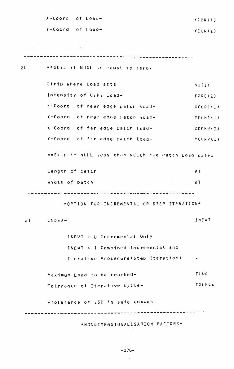
X-Coord ot Load-
Y-Coord of Load-
XCOR(I)
YCOR(I)
••Skip it NUDL is equal to zero.
Strip where Load acts
Intensity of U.D, Load-
X-Coord of near edge patch load-
Y-Coord ot near edge patch load-
X-Coord of far edge patch load-
Y-Coord of far edge patch load-
NU(I)
FORC(I)
XC0R1(I
YC0R1(I
XC0R2U
YC0R2U
*^Skip it NUDL less than NELEM i,e Patch Load case
Length of patch
Width of patch
AT
BT
•OPTION FOR INCREMENTAL OR STEP ITERATION*
21 INDEX- INEWT
INEWT = U Incremental Only
INEWT = 1 Combined Incremental and
Iterative Procedure(Step Iteration)
Maximum Load to be reached- TLOD
Tolerance of Iterative Cycle- TOLRCE
•Tolerance of .5% is safe enough
• N O N D I M E N S I O N A L I S A T I O N FACTORS^
-276-

(See Caro No 5)
2 2 SPR = pA^/Eh1* Load Normalisation Constant*
gPRl = pAVtih or SPR, a different Normalisation
Constant tor applied Load.
HA = TA2/Dh Stress Normalisation Constant*
HAM = A2/Dh or 1. Bending Moment Normalisation
Constant *
A3UU=A load stage where bending moments are desireu*
•Magnitude ot these constants can be modified to
check the results with any previously
known solution.
23 Title Card to Identify Data File
from bottom- TITLEU)
-277-

IV.4.2 Sample Input Data
Sample Data for analysing a Fully Fixed Plate
(F io. <i.44a)
CARD TYPE
FIELD DATA
RUN
PLATE
SDATA.FFSGCO/B SQUARE PLATE 5 STKIP 5 TERMS
SPR-A4/EH4-10000.SPR1-A4/DH-6 75U.HA-A2/EH2-22.VHAM-4 5.A3UU-3UU.
5
6
7
9
10
FULLY FIXED SQUARE PLATE
5,5,6,4,1.,1.,1V,1,1.15
0.0,0.0
.1b,0.
.20,0.
.30,0.
.40,0.
.50,0.
1,1,2, .10
2,2,3,.10
3,3,4,.10
4,4,5, .10
5,5,6,.10
1.,1.,0.316,0.316,.370,0.0
.33,3,0.,1.,0.,1•,5,6,25,2
-278-
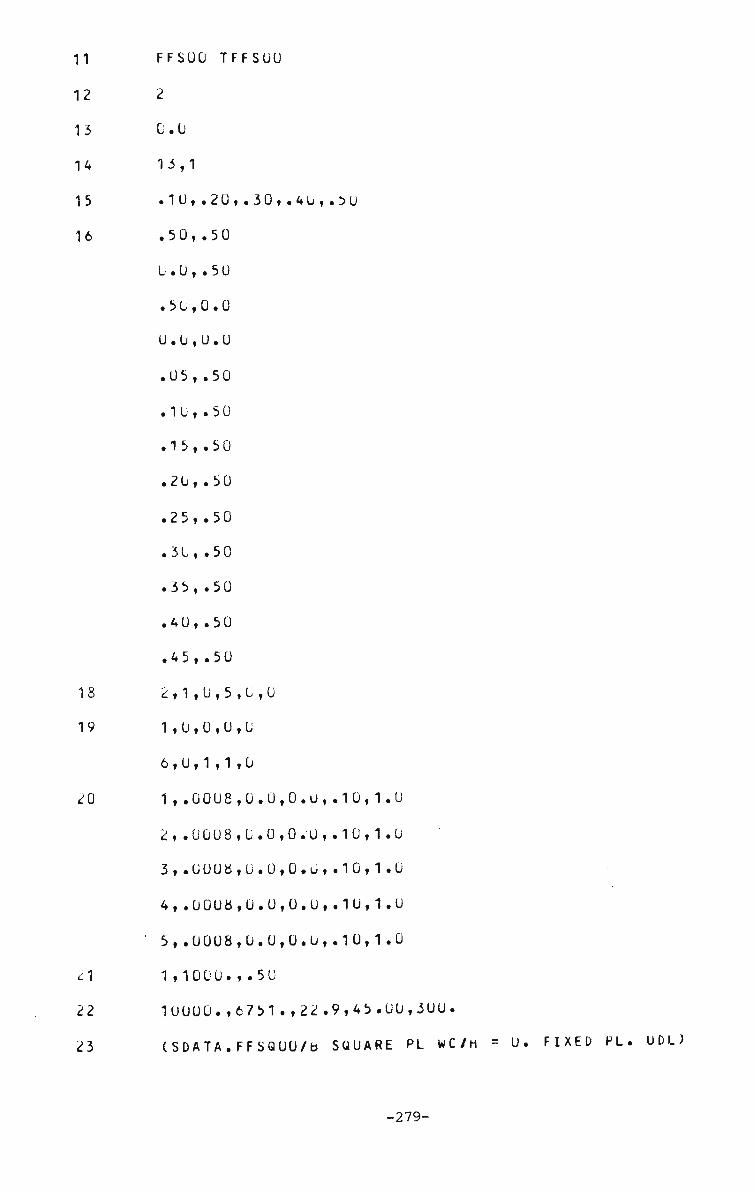
FFSOO TFFSOU
2
0.0
13,1
.10,.20,.30,.4U,.50
.50,.50
b . 0 , . 5 0
.50,0.0
0.0,0.0
.05,.50
. 1 0 , . 5 0
.15, .50
.20, .50
.25,.50
.30, .50
.35, .50
.40,.50
.45,.50
2,1,0,5,0,0
1,0,0,0,0
6,0,1,1,0
1,.0008,0.0,0.0,.10,1.0
2,.0008,0.0,0.0,.10,1.0
3,.0008,0.0,0.u,.10,1.0
4,.00U8,0.0,0.0,.1U,1.0
5,.0008,0.0,0.0,.10,1.0
1,1000.,.50
10000.,6751.,22.9,45. 00,300.
(SDATA.FFSQOU/b SQUARE PL WC/H
-279-
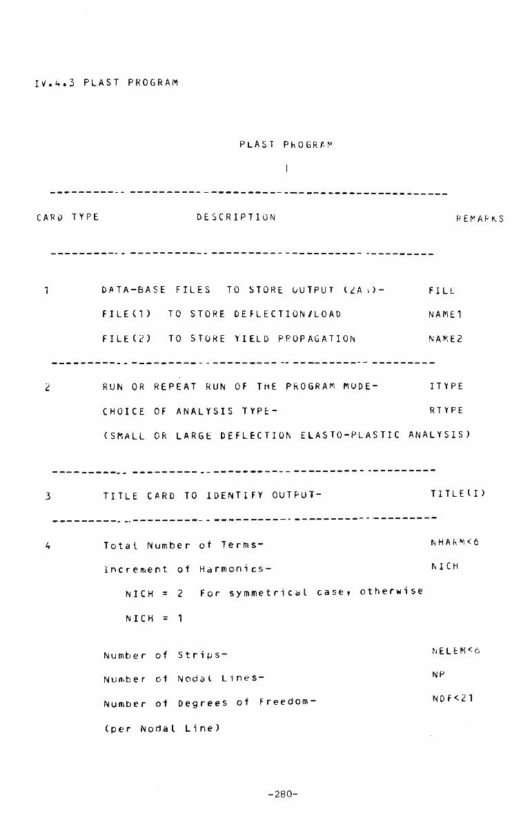
I V . 4 . 3 P L A S T P R O G R A M
P L A S T P R O G R A M
C A R D T Y P E D E S C R I P T I O N R E M A R K S
D A T A - B A S E F I L E S T O S T O R E O O T P U T ( 2 A > ) - F I L E
FILEd) TO STORE DE FLE CTI ON/LO AD NAME1
F I L E ( 2 ) T O S T O R E Y I E L D P R O P A G A T I O N N A M E 2
R U N OR R E P E A T R U N OF T H E P R O G R A M M O D E - I T Y P E
CHOICE OF ANALYSIS TYPE- RTYPE
(SMALL OR LARGE DEFLECTION ELASTO-PLASTIC ANALYSIS)
T I T L E C A R D T O I D E N T I F Y O U T P U T - T I T L E U )
Total Number of Terms- NHAKM<6
Increment of Harmonics- NICH
NICH = 2 For symmetrical case, otherwise
NICH = 1
Number of Strips-
Number of Nodal Lines-
Number of Degrees of Freedom'
(per Noda I Li ne )
N E L E M < 6
NP
NDF<21
-280-

L e n g t h ot S t r u c t u r e -
Breadth of Structure
Number of Stress Calculation Points-
AL
BW
NSTES
P o i n t ( N S T E S ) from which S t r e s s e s are Stored- N T A P
The s e l e c t e d p o i n t s are c l u s t e r e d at the rctt
(See card type 16)
Convergence Limit*-
•Iterative (step) type analysis is not fully
implemented at present.
om
TOLRC
N u m b e r of I n c r e m e n t a l S t e p s - ITR<2
INDEX IREST
I R E S T = 0 i n p l a n e u n - r e s t r a i n e c
IREST=1 Inplane restrained
INDEX
I F I X = 0 Simply S u p p o r t e d
IFIX=1 Simply Supported L & R
Clamped Opposite Ends
IFIX=2 Fully Fixed PLate
I F IX
I N D E X : INEWT
I N E W T = 0 O p t i o n for I n c r e m e n t a l Procedure
INEWT=1 Option for Step Iteration^
R a t i o of Two C o n s e c u t i v e Load
increments (Unity at this stage)- 2C
-281

•Program uses an Incremental Method at this stage.
•NODAL C O - O R D I N T E S ^
X-Coord ot Nodal L i n e s -
Z-Coord ot Nodal L i n e s -
xp
ZP
•STRIP LOCATION AND THICKNESS*
Strip N u m b e r -
Left Node N u m b e r -
Right Node N u m O e r -
T h i c k n e s s of S t r i p -
NUM
NODCI ,1 )
NODII , )
TCI)
Modulus of E l a s t i c i t y in X-
Modulus of E l a s t i c i t y in Y -
Poisson's Ratio in X-
P o i s s o n ' s Ratio in Y-
E1
E2^
PX
PY*
• O r t h o t r o p i c m a t e r i a l property can be dealt with only
in the linear elastic a n a l y s i s .
Number of Layers in P l a t e -
Number ot S u b - u i v i s i o n s in Strips
Number of X Gauss Points in Sub-div.-
Number of y Gauss Points in Sub-div.-
Unit N u m b e r -
(to store e l a s t o - p l a s t i c yield sequence)
NSLIC<V
N I C R O I
NG1<17
NG2<17
ITAPE
-282-
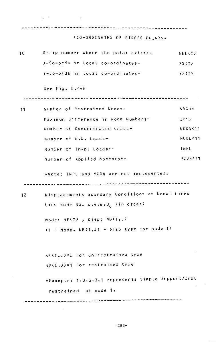
10
•CO-ORDINATES OF STRESS POINTS^
Strip number where the point exists- NELCD
X-Co-ords in local co-ordinates- XS(D
Y-Co-ords in local co-ordinates- YS(D
See Fig. K.44b
11 Number of Restrained Nodes- NBCUN
Maximun Difference in Node Numbers- IP*'J
Number of Concentrated Loaos- NC0N<11
Number of U.D. Loads- NUDL<11
Number of In-pl Loads*- INPL
Number of Applied Moments*- MC0N<11
•Note: INPL and MCON are not implemented.
12 Displacements Boundary Conditions at Nodal Lines
Lire Node No, u,v,w,0 (in order)
Node: NF(I) ; Disp: NB(I,J)
(I - Node, NB(I,J) - Disp type tor node I)
NB(I,J)=0 For un-restrainea type
NB(I,J)=1 For restrained type
•Example: 1,0,U,0,1 represents Simple Support/Inpl
restrained at node 1.
-283-
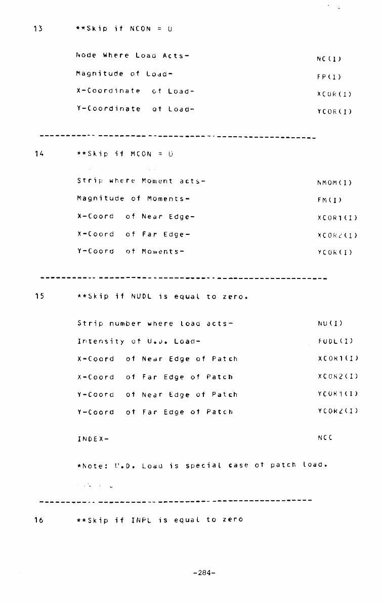
13 ••Skip if NCON = 0
Node Where Load Acts-
Magnitude of Load-
X-Coordinate ot Load-
Y-Coordinate of Load-
NC (I)
FPU)
XCOR(I)
YCORII)
14 ••Skip if MCON = 0
Strip where Moment acts
Magnitude of Moments-
X-Coord of Near Edge-
X-Coord of Far Edge-
Y-Coora of Moments-
NMOM(l)
FM(I)
XC0R1(I)
X C 0 R 2 ( I )
YCORII)
15 * ^ S k i p if N U D L is e q u a l t o z e r o .
Strip number where load acts-
Intensity ot U.i). Load-
X-Coord of Near Edge of Patch
X-Coord of Far Edge of Patch
V-Coord ot Near Edge of Patch
Y-Coord ot Far Edge of Patch
INDEX-
NU (I)
FUDL(I)
XC0R1(I)
XC0R2(I)
YC0R1 (I )
YC0R2(I)
NCC
• Note: t'.D. Load is special case of patch load.
16 ••Skip if INPL is equal to zero
-284-

Node number where loaa a c t s -
• Direction of A p p l i c a t i o n
N K I )
NL(I)= 1 Load acting along X ,u Direction
NL(I)= 2 Load acting along Y ,v Direction
NY(I)=1 Concentrated Inr-lane Load
NY(I)=2 U.D. Inplane Load
Strip number where load acts- NCCII.
••Skip if NY(I)=2
Point ot a p p l i c a t i o n ot load- YCOR(I)
Skip if NY(I)=1
Y-Coord of near edge of U.D. In-pl load- YC0R1(I)
Y-Coord ot tar edge of U.D. In-pl load- YC0R2(I)
•Type ot Load (U.D.L or Concentrated)
NCC= 1 Uniformly Distributed Load
NCC= 2 Concentrated Load
Magnitude of Load- F P U )
17 Yield Stress of M a t e r i a l - SYILD
INDEX: NWRT
NWRT = 0 For Incremental Procedure
NWRT = 1 For combined Incremental ii
Iterative Procedure(Step Iteration)^
Step at which Yield is assumed for
-285-

d e t a i l e d i n v e s t i g a t i o n it n e e d e d -
Load step reduction factor at Yield
Incremental Deflection ratio
when yield is assumed to comwence-
Point for which results art stored-
•NWRT = 1 ,This case not fully implemented
at present.
IGTR
GTR
SENS
NTAPE
-286-
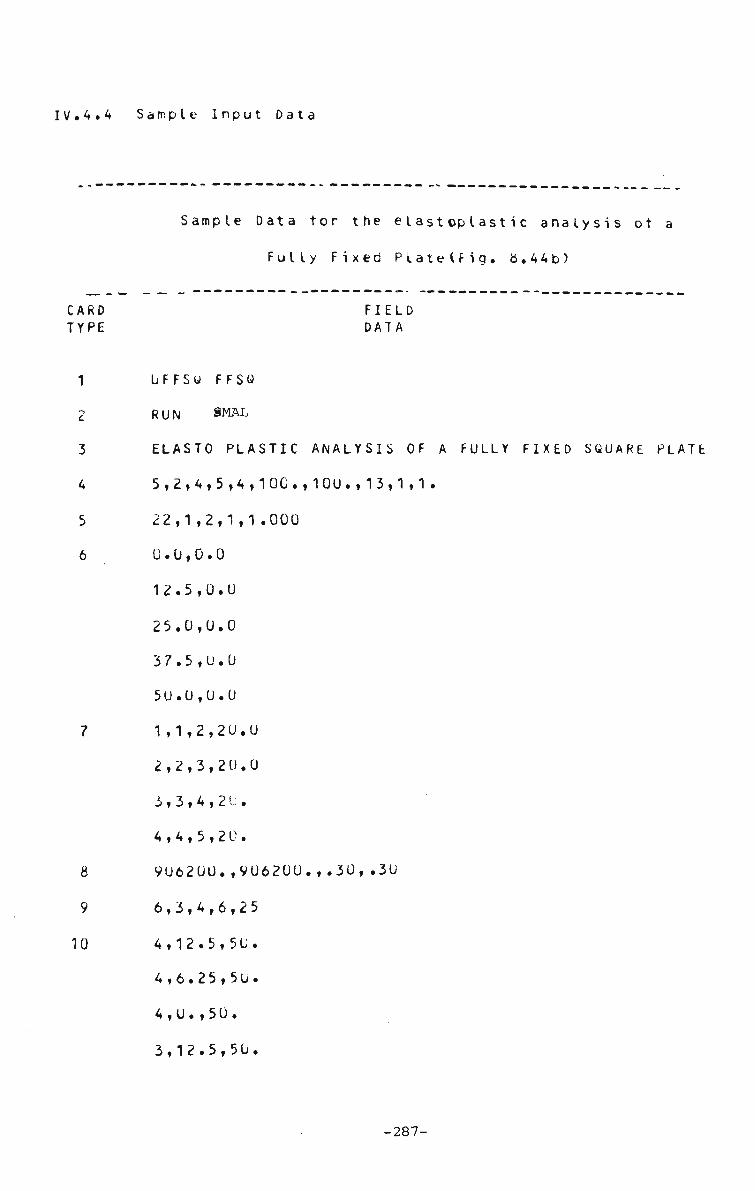
IV.4.4 Sample Input Data
Sample Data tor the elastoplastic analysis ot a
Fully Fixed PlatelFig. b.44b)
CARD FIELD TYPE DATA
1 UFFSu FFSu
2 RUN SMAL
3 ELASTO PLASTIC ANALYSIS OF A FOLLY FIXED SQUARE PLATE
4 5,2,4,5,4,100.,100.,13,1,1 .
5 22,1,2,1,1.000
6 0.0,0.0
12.5,0.0
25.0,0.0
37.5,0.0
5U. 0,0.0
7 1,1,2,20.0
2,2,3,20.0
3,3,4,21:.
4,4,5,20.
8 906200.,906200.,.30, .30
9 6,3,4,6,25
10 4,12.5,50.
4,6.25,50.
4 , 0. , 5 0 .
3,12.5,50.
-287-

3,6.25,50.
3,0.00,50.
2,12.5,50.
2,6.25,50.
2,0.00,50.
1,12.5,50.
1 ,6.25,50.
1,0.00,50.
4,12.5,0.0
2,1,0,4,0,0
1 ,0,0,0,0
5,U,1,1 ,0
1,6.0,0.0,12.5,0.0,100.
2,6.0,0.0,12.5,0.0,100.
3,6.0,0.0,12.5,0.0,100.
4,6.u,0.0,12.5,0.0,100.
150.0,0,8,.2C,1.75,1

LIST OF REFERENCES
1. AALAMI, B. Large deflection of elastic plates under
patch loading. Proc.Journal ot Struct.Div.,
Proc.A.S.C.E. , Vol .98,No.ST11,Nov.1972, pp2567-25b6.
c, AALAMI, B and J.C. CHAPMAN., Discussion of Proceeding-
of Institution of Civil Engineers, London, Vol.44,
November 1969, pp263-264.
3. ADOTTE, G.D., Second-order theory in orthotropic
plates. Journal of Struct. Div., Proc. A.S.C.E.,
Vol.93,No.ST5, October, 1967, pp343-362.
4. ANG. A.N.S., and A.L. LOPEZ, Discrete Mode
elastic-plastic plates. Journal ot Engg
A.S.C.E., Vol. 94, No. EM1, Proc. Paper
1968, >p271-293.
5. ARGYRIS, J.H. Recent advances in matr
structural analysis. Pergamon press, 1964
6. ARGYRIS,J.H. Continua and discontinua.
Matrix Methods in Struct.Mech.,A.F. I
Technology. ,Wright Patterson A.F.B., Oc
ppii-i9o.
7. ARMEN, H.,A.B. PIFK0,H.S. LfcVlNE, and
Plasticity, Chapt.tt ot Finite Element Techniques in
Structural Mechanics, edited by H. Tottenham and C.
I analysis of
. Mech. Div.,
58U9, Feb.
i x met hods ot
•
P roc.C ont.on
nstitute ot
tober 1965,
G. ISAKSON.
-289-

Brebbia, Southampton University Press, England, 197U.
b, BACH, C, Elasticititat uno Festigkeit, 3rd ed.,Julius
Springer, Berlin, 1«9b, pp552-564.
9. BACKLUND, T. and H. wENNERSTROM., Finite element
anatysis ot elasto-plastic shells., Int. J. Num. Metr .
Engrg., Vol.8, 19r"4, pp4l5-424.
10. BARNARD, A.T. and P.W SHARMAN., The eIasto-pIasti-
analysis of plates using hybrid finite elements Int. J.
Num. Meth. Engrg. VoI.1U,No.6,1976., PP1343-1356.
11. BASU, A.K. and J.C. CHAPMAN, Large deflection behaviour
of transversely loaded rectangular orthotropic plates.
Proc. Inst. Civ. Engrs. Vol.35 September, 1966 p79
12. BELYTSCHKO, T. ano M. VELEBIT., Finite element method
tor elastic plastic plates, Journal of Eng.Mech.Div.,
Proc. A.S.C.E., No. EM1,ST24, February 1972, PP227-242.
13. BERGER, H.r. , A new approach to the analysis of large
deflections ot plates, Journal of Applied Mechanics,
Vol.22,No.4, December 1955, pp465-472.
14. BHAUMIK, A.K. ano J.T. HANLEY. E I asto-pI astic plate
analysis by tinite differences. Journal ot
Struct.Div., Proc.A.S.C.E.,0ct.1967, pp279-294.
15. 6RADFIELD, CD., Collapse of rectangular outstanos
loaded in comression., Stability of Steel Structures.,
Prel. Report IABSE Regional Colloquium, Lieoe, 13-15
April, 1977pp315-320.
-290-

BREBBIA, C. and J. CONNOR. Geometrically non-linear
tinite element analysis. Journal of Eng.Mech.Div.,
Proc .A.S.C .E. , Proc.Paper 6516t Vol.9b,April 1969,
PP463-483.
bPOWN, T.G. and A. GHALI., Semi-analytic solution of
skew olate bendiny, Proceedings lnstn. Civ.Enqrs.,
London, TN 92, March 1974, pM65-175.
BPOWN, T.G. and A. GHALI., Finite strip analysis ot
quadrilateral plates in bending, Journal of
Enu.Mech.Div., Proc. ot A.S.C.E.t Technical Note, No.
EM2, April 1978, pp480-484.
BURAGOHAIN, D.N. Discrete strip analysis ot multiple
folded plates and multicell box section bridges. Indian
Concrete Journa I.,Vol.47 ,No.3, March 1973.
BURAGOHAIN, D.N. and S.C. PATODI., Large deflection
analysis of plates and shells by discrete energy
siethod. Computers and S t ructures • , Vol .9, 1978,
PP315-322.
CARLSEN, C.A., T.H. SUREDIE, and N.T. NORDSVE.,
ultimate load analysis of the compression flange of a
bcx girder, Stability ot Steel Structures., Prel.
Report IABSE Regional Colloquium, Liege, 13-15 April,
1977 pp257-266.
CHAN, K.S., CL. LAW and D.W. SMITH., Stability ot
stiffened compression flanges unaer inplan* forces ana
wheel loads. Stability ot Steel Structures, Prel.
-291-

Report, IABSE Regional Colloquium, Lie'ge, 13-15 April,
1977, pp289-304.
CHEN, K.K. A triangular plate tinite element tor
large-displacement elastic-plastic analysis of
automobile structural components. Computers ana
Structures, Vol.10,1979, pp203-215.
CHEONG, M.S., Y.K. CHEUNG, and A. GHALI., Analysis of
slabs and girder bridges by the tinite strip method.,
J. Build. Sci., Vol. 5, 1970, pp95-104.
CHEUNG,Y.K. Finite strip method in the analysis ot
elastic plates with opposite simply supported encs.
Proc. Instn.Civ.Engrs,London,Vol 40,May,196b, pp1-7.
CHEUNG, Y.K., The analysis of cylindrical orthotropic
curved bridge decks, Publications, IABSE, Vol. 29-11,
December 1969, pp4l-49.
CHEUNG, Y.K., Finite strip method in structural
analysis, Pergamon Press Ltd., New York,1976.
CICIN, P. Eetrachtungen uber die Bruchursachen der
neuen Wiener Donaubrucke. , Tiefbau, Vol. 12, 1970,
PP665-674.
CCAN, J.M. Large deflection theory for plates with
bmall initial curvature loaded in edge compression.
Journal of Applied Mech., 18,2,June 1951, po143-151.
COVILLE, J.,E.B. BAKER and R.W. FURLONG., Journal of
Struct.Div. Proc. A.S.C.E., Vol.99, N0.ST3, Proc.
-292-

Paper 9 5 9 3 , M a r c h , 1973, p p 3 4 9 - 3 6 4 .
31. CRISFIELD, M.A., Large deflection elastoplastic
buckling analysis of eccentrically stiffened plates
us inc, tinite elements., TRRLt Laboratory Report
225 , Crowthorne, Berkshire, 1976.
32. CRISFIELD, M.A. Some approximations in the non-linear
analysis ot rectanyular plates usinc tinite elements.
Department ot Environment., TRRL Report 51UC.
Crowthorne,1973 (Transport and Road Research
Laboratory)
33. CRISFIELD, M.A. Large-detIection elasto-plastic
buckling analysis of plates using finite elements.
Department of the Environment. , TRRL Report LR593.
Crowthorne,1973., (Transport and Road Research
Laboratory).
34. DAWSON, R.G. and A.C WALKER. Postbuckling of
geometrically imperfect plates. Journal of Struct.
Div., Proc.A.S .C .E. , J an .1 9 tl, ST 1, i.p/5-94.
35. DESAI, CS. and J.F ABEL., Introduction to the tinite
element method, Von Nostrand, Reinhold Company, N.Y,
1972.
36. Design ot Plate and Box Girders tor Ultimate Strength,
Proceedings of IABSE Colloquium, London, March
25-26,1971, Leemann Zurich 1972.
37. DJUBEK, J. and 1. BALA2., Compressed orthotropic
rectangular webs ot steel bridges. Stability ot Steel
-293-

Structures, IABSE,RegionaI Colloquium, Budapest,
Balatonfured, 19-21 October, 1977 pp263-272.
DJUBEK, J. and M. SKALOUD., Czechoslovak approach and
the design of large intensity stittenea compression
flanges of steel box girder bridges. Stability of Steel
Structures., Prel. Report IABSE Regional Colloguium,
Liege, 13-15 April, 1977, ppT49-256.
DOWLING, P.J. Stength ot Steel box-girder bridges.,
Journal St ruet .Div ., Proc. , A.S.C.E. Vol.101,No. ST9,
September, 1975, pp1929-1946.
DOWLING, P.J., Report on Box Girders.,Final Report,
Stability of Steel St ruetures.,IABSE Regional
Col loquiurn,Lie'ge, April 13-15, 1977.
DUBAS, P. Essais sur le comportement postcritique de
poutres en caisson raidies. Colloque ae I'AIPC Design
of plate and box girders tor ultimate strength, Londres
25 et 26 mars 1971 (a paraitre).
DUPIUS, G.A.,H.D. HIBBITtS.F. MCNAMARA and P.V. MARCAL.
Nrn-linear material and geometric behaviour of shell
structures. Computers and Structures, Vol.1,1971,
PP223-239.
FALTUS, F. and M. SKALOUD., Accidents on steel bridges
and lessons to be drawn out on them., (In Czech).
Inzenyrske stavby, No.2.
FALTUS, F. and M. SKALOUD., Insegnamenti da trarsi da
alcuni dissesti di travet da ponte in lamiera
-294-

irrigidita d acciaio., Costruzioni Metalliche, No.2.
FARKAS, J. The effect ot residual welding stresses on
the buckling strenyth of compressed plates. Stability
of Steel Structures, IABSE, RegionaI Colloquium,
Budapest, BaIatontured, 19-21 October, 1977cp299-306.
FAULKNER, D. et al., Synthes's of welded grillages to
withstand compression and normal loads., Computers and
Structures, Vol.3, uo.2,1973bp221-24 6.
FILON, L.N.G., On a quadrature formula tor
trigonometric integrals, Proc. Roy.Soc., Edinburgh,49,
1928, pp38-47.
FOK, W.C. and A.C wALKER., The inelastic ultimate loao
of stiffened plate with stiffener failure., Stability
of Steel Structures., Prel. Report IABSE Regional
Colloquium, Liege, 13-15 April, 1977, pp267-272.
FRIEZE, P.A. ultimate load behaviour ot steel
box-girders and their components. Ph.D.Thesis,
Imperial College of Science and Technology, London,
lc75.
FUNG, Y.C., Foundation ot solid mechanics, Prentice
Hall,Int. Englewood Cliffs, New Jersey,1965.
GALLAGHER,R.J. Geometrically non-linear finite element
analysis. Proc.Specia I ity Conf.on Finite Element
Method in Civil Engineering, MontreaI,Canaaa,1972,
ppl-33.
<-295-
52. GALLAGHER,R.J . and J.PADLOG. Discrete element approach
to structural stability. Am.Inst. of Aero. Astro.
Journa I ,Vol .1 , No.6, June 1963, pp1437-1439.
53. GALLAGHER, R.J . ,R.A . GELLATY . , J.PADLOG and R.H.MALLET.
A discrete element procedure for thin shell instabilty
analysis. Am.Inst.ot Aero.anc Astro.Journal,
Vol .5,No.1,January 1967, ppi:8-145.
54. GRAVES SMTTH,T.R. The effect o1 initial imperfections
on the strength of thin-walled box columns. Int.Journal
of Mech.Sci., Vol.13,1971, pp911-925.
55. GRAVES SMITH,T.R. The postbuckling behaviour ot a
thin-walled box beam in pure bending. Int.Journal of
Mech.Sci., Vol.14,No.1, November 1971, pp711-722.
56. HARDING, T.E., R.E. HOBBS and B.G. NEAL., The
elastoplastic analysis of imperfect square plates under
inplane loading. Proc. Instn. Civ. Engrs.,London, Part
2, 1977,63,March, pp137-158.
57. HASKELL,W.E. Geometric non-linear analysis of thin
plates by finite elements. Ph.D. Thesis.,University of
Massachusetts,1970. pp2081-2105.
5fc. HILL, R. The mathematical theory ot plasticity.
Clarendon Press, Oxford. 1950.
59. HODGE, P.6.Jr., Plastic analysis ot structures, McGraw
Hill Book Co., Inc.,New York, 1959, ppl95-2u5,249-^69.
60. HODGE, P.G. and A.A. McMAHON., A simple finite element
-296-

model for elasto-plastic plate bending., Computers and
Structures, Vol.2, NO.5/6,1972, pp841-a54.
HOLAND,I. ano T.MOAN. The finite element in plate
buckling. Finite element methods in stress analysis.
Edited by Holand and Be I I, Tapir,1969, pp
ILYUSHIN, A.A. Plasticite, Editions Eyrolles, Paris,
1956.
INGERSLEV, A., The strength ot rectangular slabs,
Journal Institute of Structural Engineers, London, Vol.
1, January 1923, pp3-14.
IYENGER, S.N.S, Elastic and inelastic thin plate theory
and its applications; Ph.D.Thesis. Lehigh University,
1973.
JOHANSEN, K.W., The ultimate strength ot reinforced
concrete slabs., Final Report, 3rdCongress,
International Association for Bridge and Structural
Engineering, Liege, Belgium, September 1948, pp565-570.
KAPUR,K.K. and B.J.HARTZ. Stability of plates using
the finite element method. Journal ot Eng. Mech.Div.,
Proc.A.S.CE.,Vol.92,EM2,April 1966, pp177-195.
KARENSKY, 0. An engineer's ethics. Structural Engineer,
December 1970.
LEE, H.P. and P.J. HARRIS., Post-buckling strength of
thin-walled members, Computers and structures,
Vol.10,1979, pp689-702.
-297-

LEVY, S. Bending of rectangular plates with large
deflection. NACA Technical Note 846, 1942.
LEVY, S. and S. Greenman., Bending with large
deflections under normal pressure, NACA, Technical Note
853,1942.
LHOTAKOVA, I., and M. SKALOUD., Experimental
investigation into the limit state of the compression
flanges ot steel box-girder bridqes. Stability of
Steel Structures, IABSE»Regiona I Colloquium, Budapest,
Balatonfured, 19-21 October, 1977pp219-229.
LIN, T.H. and E. HO. Elastoplastic bending of a thin
rectangular plate. Journal ot Eno.Mech.Div.,
Proc.A.S.C.E.,Vol.94,EMlf1968, pp199-210.
LIN, T.H., S.R. LIN and B. MAZELSKY. Elastoplastic
oenaing of rectangular plates with large oeflection.
Journal of Applied Mech.,Dec.1972, pp978-9b2.
LOO, Y.C., Development and application ot the finite
strip method in the analysis of right bridge decks,
Ph.D Thesis, Department of Civil Engineering,
University of Dundee, 1972.
LOO, Y.C. and A.R. CUSENS., Finite Strip Method in
Bridge Engineering, C & C.A. Publishing Division,
London, 220P, 1978.
L0TTER0TH, A. and I. KRETZSCHMAR., "Experimente I Ie una
theoretische untersuchungen zum beuIverha It en
ansgesteifter bleche als grunalage fur die neufassung
-298-
der stabilitatsvorschirtt., Stability ot Steel
Structures, IABSE,Regiona I Colloquium, Buaapest,
Balatonfured, 19-21 October, 1977, pp219-229.
77. MALAIV0N6S, K., T. HONGLADAROMP and S.L. LEE., Finite
element analysis ot elastic-plastic plate bending based
upon Tresca yield condition. Proc. 3rd Int. Cont. on
F.E. Methods. Universit; of New South wales,
Australia, July, 19 79, pp24 7-263.
78. MALLET, R.H. and P.V. MARCAL. Finite element analysis
of non-linear structures. Journal of Struct. Div.,
Proc.A.S.CE. , Vol .94,No.ST9, Se pt embe r , 1 968 ,
79. MALLET, R.H. and L.A. SCHMIT. Ncn-linear structural
analysis by energy search. Journal of Struct.Div.,
Proc.A.S.CE., Vol. 93, No. ST3, June 1967, pp221-234.
80. MANSFIELD, E.H., The bending ana stretching of plates,
Aeronautics and Astronautic Int., Vol.6, The MacMillan
Co. N.Y.,1964.
81. MAQ00I, R. Measurements of the initial deflections of
stiffened panels of large box-girder bridges (in
French) IABSE Publications 1971,31, part 2 pp14l-151.
82. MAQ00I, R. and CH. MASSONNET, Non-linear theory of
postbuckling resistance of large stiffened box girders.
IABSE Publication, Vol. 31,partII 1971, pp91-140.
83. MARCAL, P.V. Finite element analysis of combined
problems of non-linear material and geometric
behaviour. Proc. American bot. Mech .Eng.Conf. on
-299-
Computational approaches in Applied Mech.,June 1969,
PP133-149.
MARCAL, P.V. and I.P. KING. EI astic-pI astic analysis of
two dimensional stress systems by the finite element
Kiethoa. Int.Journal ot Mech.Sci., Vol.9,No.3,1967,
PP143-155.
MAR6UERRE, K. Zur Theorie der gekrummten Platte grosser
Formanderung. Proc. Fifth Int. Congress of Appl.Mech.,
Cambnoge,Mass , 193tt pp93-10l.
MARTIN,H.C On derivation of stiffness matrices tor
the analysis of large deflection and stability
problems. Proc.Conf.on Matrix Methods in
Struct.Mech.,A.F.Institute ut Tecnnoloqy.,Wright
Patterson A.F.B., October 1965, UFFDL-TR 66-BO)
MASSONNET, C General theory of elasto-plastic
membrane-plates. Engineering Plasticity, edited by J.
Heyman and F.A.
196B, pp443-473.
Leakie, Cambridge University Press,
MASSONNET, C and R. MAQUOI., The conventional design
of box girders is unsafe and must be the cause of the
recent collapse ot three large box girder bridges.
Final Report, IABSE
MASSONNET, CH. and R. MAQUOI. New theory and tests on
the ultimate strength of stiffened box girders.
Proceedings of International Conference on Steel Box
Girders, ICE Colloquium, London, 25-26 March 1971.
-300-

90. MOXHAM, K . E . Theoretical prediction of the strength of
welded steel plates in compression. Cambridge
University Report No.CUED/C - Struct/TR2,1971.
91. MURRAY, D.W. and E.L. WILSON, An approximate nonlinear
analysis of thin plates. Proc. 2nd Conf. Matrix
Methods Struct. Mech., Wright-Patterson, A.F.B., Ohio,
December,1968, pp1207-1230.
92. MURRAY, D.W. and E.L. WILSON. Finite element large
deflection analysis of plates. Journal ot
Eng.Mech.Div. , VoI . 95,No . EMI, Feb.1969, JP143-165.
93. MURRAY, D.W. and E.L. WILSON. Finite element
postbuckling analysis of thin elastic plates. American
Inst.of Aero.S Astro,Jrnal,Vol.7 ,1969, pp1915-1930.
94. NAYAK, G.C and O.C Z1ENKIEWICZ., Elasto-plastic
stress analysis; A generalisation for various
constitutive relationships including strain softening.
Int .Journal of Numerical Meth.in Eng.,1,1969,
rp75-100.
95. NAYAK, G.C. and O.C. ZIENKIEWICZ., Note on the "alpha"
constant stiffness method tor analysis of non-linear
problems., Int. J. Num. Meth. Engg.,4,1972, pp579-5&2.
96. ODEN, J.T. Numerical formulation ot non-linear
elasticity problems. Journal of Struct.Div.,
Proc.A.S.C.E.Vol.93,No.ST3, Paper 5290,June 1967,
PP235-255.
97. ODEN, J.T., Finite element applications in non-linear
-301-

98.
structural analysis. Proc. ASCE, Symposium on
Application of F.E. Method in Civil Engineering,
Nashville, Tennessee, November 13-14, 1969, pp419-456.
POPE, G.G., The amplication ot the matrix displacement
method in plane elasto-plastic problems, Proc. Conf.
Matrix Meth. Struct. Mech., Wright-Patterson
A.F.B.,0hio, Oct.1965, pp635-654.
99. PRICE, J.F., Discussion on quadrature formulas tor use
on digital computers, Boeing Scientific Research Labs.
Report D1-82-0052, May 1960.
100. Regional Colloquium on Stabilty of Steel
Structures.,IABSE, Tokyo, September 9 1976.
101. Regional Colloquium on Stabilty ot Steel
Structures.,IABSE, Liege, April 13-15, 1977.
102. Regional Colloquium on Stabilty of Steel
Structures.,IABSE, Washington, May 17-19, 1977.
103. Regional Colloquium on Stabilty of Steel
Structures.,IABSE , Budapest - Ba latonfured, October
19-21, 1977.
104. REISSNER, E., On some aspects ot the theory ot thin
elastic shells, J.boston Soc.Civ.Engg., Vol.42, 1955,
PP100-133.
105. ROARK, R.J. and w.C Young, Formulas tor Stress and
Strains, McGraw-Hill Inc., 5th Ed.,1975, p171.
106. ROBERTS, T.M. and D.G. ASHWELL., The use of finite
-302-

element miaincrement stiffness matrices in the
post-buckling analysis ot imperfect structures. Int.
J. Solids Structure Vol.7 1971, pp805-823.
107. ROIK, H.K. Nochmals: Betrachtungen uber die
Bruchursachen der neuen Wiener Donaubrucke ., Tiefbau,
Vol. 12,1970, pp1152.
108. R00VE, B., Comportement non-lineaire des plaques
comprimees munies de raioisseurs en caisson, par.,
Stability of Steel Structures., Prel. Peport IABSE
Regional Colloquium, Lie>e, 13-15 April, 19 7 7,
pp273-278.
109. RUSTON, K.R. Large deflection of plates with
unsupported edges. Journal of Strain Analysis,
Vol.7,No.1,1972, pp44-53.
110. SATTLER, K. Nochmals: Betrachtungen uber die
Bruchursachen der neuen Wiener Donaubrucke., Tiefbau,
Vrl. 12,1970, pp94b-950.
111. SCHLINDLER, A. Stability problems and shear lag
phenomenon., Stability ot Steel Structures,
IABSE,Regional Colloquium, Budapest, Ba latontured,
19-21 October, 1977 pp287-297.
112. SCHMIT, L.A., F.K. B0GNER and R.L. FOX. Finite
deflection structural analysis using plate and shell
discrete elements. Am.Inst .Aero. anc Astro.
Journal,Vol.6,No.5,1968, pp1525-1527.
113. SHULL, H.E and L.W. HU., Load carrying capacities of
-303-

simply supported rectangular plates., Jounal of Applied
Mechanics, Vol. 30,1963, pp617-621.
113. SHYE. KUEN-YAW and T. COVILLE, Post-buckling tinite
element analysis of flat plates, Journal of
Struct.Div.,Proc.,A.S.C.E., Vol.105 No.ST? February,
1979, ^297-311.
115. SKALOUD, M. Post-buckled behaviour ot stiffened webs.
Academia Nork laaate Istoi Ceskoslovenske Akademie
vED,Pe rgue,1970.
116. SKALOUD, M., General Report on Plate and Box Girders,
Theme 5, Final Report, Stability ot Steel Structures,
IABSE,Regiona I Colloquium, budapest, Ba latonfured,
19-21 October, 1977, pp133-14U.
117. SKALOUD, M. and R. NOVOTNY., Post-critical behaviour ot
an initially curved uniformly compressed panel.,
reinforced in its middle by a longituainal stiffener.
(in German) Acta. Technica, CSAV.No. 2, 1965.
118. SOLIMAN, M.I., S.M. MIRZA. and 6.R. THOMAS., Finite
element analysis of a reinforced concrete box giraer
bridge., Proc. 3rd Int. Conf. F.E. Methods. University
of New South wales, Australia., July 1979, rp299-314.
118a STRANG, W.G., and b.J. FIX., Analysis ot tinite element
method. Prentice-Hall Inc., fcnglewooa Cliff., New
Jersey, 1973.
119. SURYANARAYANA, A. and J. RAMACHAND RAN., Larte
-304-

deflections ot rectangular orthotropic plates with
non-linear stress-strain relations., Computers and
Structures, Vol. 8,1978, pp93-V8.
120. SZILARD, R., Theory and analysis ot plates, classical
and numerical methods., Prentice-Hall Inc., Englewood
Cliffs., New Jersey, 1974, p340.
121. Steel Box Girder bridges, Proceedings ot International
conference of I.C.E. London, 13-14 February 1973.
122. Th. von KARMAN. Encyklopadic der Mathematischen
wissenschaften, VoI.4,Teubner.,1910, p349.
123. THOMPSON, J.M.T. and A.C. WALKER. A non-linear
perturbation analysis ot discrete structural systems.
Int. Journal of Solids & Structures,4,1968, pp757-767.
124. TIM0SHENK0, S.P. and S. W0IN0WSKY-KRIEGER, Theory of
Plates and Shells., 2nd Ed. McGraw-Hill Book Company,
1959.
125. TRESCA, H. Comptes Rendus, Academie des Sciences,
Paris,Vol. 59, 1864, p754.
126. TORNER,M.J.,E.H.DlLL.,H.C.MAkTIN. and R.J.MELOSH.,
Large deflection of structures subject to heating and
external loads. Journal of Aerospace Sciences,
Vol .2?tFebruary 1960.
127. VOLMIR, A.S., Flexible plates and shells, Translated
from Russian, TR 66-216, 16967, Air Force Flight
Dynamics Lab., Air Force Base, Ohio, pp13-14, 74-84.
-305-

128. VON MISES, R, Mechcinik der plastischen Formanderung der
Kristallen Z.angew.Math.Mech.8,1928, pp161-185.
129. VON RIESEMANN,w.A. Large deflections of elastic beams
and plates using the finite element met bod.,ph.D.
Thesis,Standford 0niversity,1968.
130. WALKER, A.C. A non-linear finite element analysis ot
shallow circular arches. Int. Journal of Solids &
Structures,5,1969, ppV7-1U7.
131. WALKER, A.C. The postbuckling behaviour ot simply
supported square plates. Aeronautical Quarterly,
20,3,Aug.1969, pp2b3-226.
132. WANCHOO, M.K. Post-elastic tinite element analysis ot
reinforced plates., Ph.D.Thesis., University of New
Mexico.,1972.
133. wEGMULLER, A.W. Elastic-plastic finite element analysis
ot plates. Proc. Instn. Civ. Engrs.,London, Part
2,57,September , 1974., pp535-543.
134. wEGMULLER, A.'*. Inelastic response of plates and
eccentrically stiffened plates. Proc. 3rd Int. Conf.
F.E. Method, University of New South Wales, 1974,
PP677-7U1.
135. WHANG, B. Elasto-plastic orthotropic plates and shells.
Proc. Symp. on Application ot Finite Element Methods in
Civil Engineering, School ot Eng. Vanaerbilt
university,A.S.C.E.,1969, pp481-516.
-306-

136. WILLIAMS, D.G. Some examples ot the elastic behaviour
of initially deformed bridge panels. Civil Eng. & Pub.
wks. Rev.,Oct.1971 , pp1107-1112.
137. WINTER, G., Performance ot thin steel compression
flanges, Congress del'AlPC, Liege, Publication
Pre liminaire, 1948, pp137-148.
138. uOLMIR, A.S. Flexible plates and shells (in German)
VEB fur Bauwesen, Berlin, 1962.
139. WOOD, R.H., Plastic and elastic design ot slabs and
plates, Thames and Hudson, London, 1961, pp24-26.
140. YAM, L.C.P. and P.C. DAS. Elastoplastic analysis of
reinforced concrete slabs - some implications of limit
state design. Proc .Int.Cont. on Development in Bridge
Design and Construction, Cardiff, 1971, editea by K.C
Rockey, J.L. Bannister and H.R. Evans,pub.Crosby
Lrckwood, London, ppl44-160.
141. YAMADA, Y.,N. YOSHIMURA and T. SAKURAI. Plastic
stress-strain matrix and its application tor the
solution of elasto-plastic problems by the finite
element method. Int. J .Nurr .Met h . in Eng., Vol.10,1968,
PP343-354.
142. YAMAKI, N. Postbuckling behaviour of rectangular plates
with small initial curvature loaded in eage
compression. Journal of Applied Mech., 26,3,Sept.1959 ,
PP407-414.
143. YANG, T.Y. A finite element large deflection analysis
-307-
of plates with initial deflections. AIAA Journal Vol.9
No.8 August 1971, pp1468-1473.
144. YANG, T.Y. Finite displacement plate flexure by the use
ot matrix incremental approach. Int.Journal ot
Numerical Meth.in Eng.,4,1972, pp415-432.
145. YILMAZ, C Ultimate strength ot box girders by tinite
element method., Ph.D. Thesis., Lehigh University.,
1975.
146. ZIENKIEWICZ, O.C, S. VALLIAPAN and I.P. KING.
Elasto-plastic solutions of engineering problems.
Initial stress, finite element approach.
Int.J.Num.Meth. in Eng., Vol.1,1969, pp75-lOU.
147. ZIENKIEWICZ,O.C. and Y.K. CHEUNG., Finite element
method in structural and continuum mechanics.,
McGraw-HiII,New York,1967.
PROFILE - NEXT...
-308-

PROFILE
SUBRATA KUMAR MAITRA
Subrata k Maitra was born in Inaia in 1946 ana i
with two children.
married
Mr. Maitra graduated in 1966 fro» Burdwan University in
India. During 1968-1975, he worked on research, design and
consultancy projects in structural/civil engineering while
he was working as Lecturer in structural engineering in his
mother institution. Subsequently he received a Master of
Engineering in Structural Engineering (1972) and M. Engg.
Sc.(1977) degrees from Burdwan and Adelaide Universities
respect i vely.
Mr. Maitra's specialised field is the development and
amplication of finite element method in solving nonlinear
elastic and elastoplastic problems in plates and box-girder
bridges. He has more than seven years of experience in
scientific and engineering computing. He has worked
extensively in the field ot computer graphics and its
application in structures, chemistry (quantum mechanics)
fluid and soil mechanics problems.
Mr. Maitra has joined Control Data Australia Pty. Ltd. as a
Sr. Engineering Analyst from September 1981. He provides
consulting support in range ot projects which involve
-309-

finite e l e m e n t a n a l y s i s of large s t r u c t u r e s , highway design
and terrain modelling by MOSS, non-linear heat transfer
analysis, slope stability analysis ana elasto-plastic
analysis of fans used in power station. Projects recently
completed are the structural analysis of three mixed flow
tano, lawn mower base plate analysis by MSC/NASTRAN
soft-ware. These projects involve preparation of proposal,
modelling of structures, man hour and machine time
management, and writing of reports based on the finite
element analysis results. Mr. Maitra aUo supports
Slope-II, Triflex (piping design) and various other tinite
element software, available on Cybernet.
Currently he is working on the foilowing technical papers
tor publication.
i. G e o m e t r i c a l l y n o n l i n e a r analysis ot plates by
tinite strip method.
ii. Elasto-plastic analysis of plates by finite strip
method.
iii. Large deflection elasto-plastic analysis of plates
by finite strip method.
iv. Solution of nonlinear tinite strip stiffness
equat i ons .
Large d e f l e c t i o n finite strip a n a l y s i s ot plates
-310-
with initial a e f l e c t i o n s .
vi. " S e g m e n t e d Finite S t r i p " method tor non-linear
a n a l y s i s ot s t r u c t u r e s .
vii. Application of computer graphics in the
e l a s t o - p l a s t i c a n a l y s i s of s t r u c t u r e s .
viii. Nonlinear analysis ot plaxea structures by finite
strip m e t h o d .
IIIIIIIIIIIMIMM.il
I I o o o o o o o o o o o o o o o o o t I
1 1 I I I I I I I I I I I I I I I I III
-311-