Embed Size (px)
Citation preview

Figure I. Primary reformer firing controls.
for
Here is a review of the to personnel, equipment,and overall in synthetic manufacturing.
A. M. Caiabrese and L. D. Krejci, The M. W. Kellogg Co., Houston, Tex.
Ammonia production utilizing the direct synthesis ofnitrogen and hydrogen has over the past generation be-come the major source of ammonia required in the pro-duction of chemical fertilizers. The modern single-trainammonia plant requires a coordinated approach to safetyinstrumentation due to 1) greatly increased throughput,2) the utilization of centrifugal compressors, 3) a highlyintegrated heat exchange system, and 4) the high-pres-sure reforming reactor and low-pressure synthesisconcept.
A large plant of recent design offers lower initial invest-ment and reduced operating expense per ton of produc-tion. In exchange for these benefits, the designer andoperator must provide greater control instrumentationreliability to minimize down-time and maintain a highonstream factor. Due to the single-train concept in design,even a brief plant outage can be serious in terms of lostproduction.
Three centrifugal compressors are basic to all high-capacity single-train ammonia units. They are the pro-cess air compressor, the synthesis gas compressor, and
the ammonia refrigeration compressor. Each has its owncharacteristic antisurge, speed control, and safetyrequirements.
Effective recovery of all available heat is essential tolow-cost large-scale ammonia production. An integratedheat exchange system effectively recovers waste heat,utilizing process gas, process air, boiler feed-water pre-heat, and steam superheat coils within the primaryreformer.
A large quantity of steam is required as a process re-actant and to power the numerous pump and compressorsteam turbines. Therefore, 1,500 lb./sq. in. gauge steamis generated by heat exchange between boiler feed-waterand hot process gases at various points in the process. Inaddition, many boiler feed-water pre-heat exchangers areprovided throughout the process.
The objective of ammonia plant safety instrumentationis protection of personnel, mechanical equipment, andcatalyst inventory. Activation of plant shutdown systemsfor any other reason is unnecessary.
With fired furnaces, boilers, high-pressure high-

figure 2. Steam/feed gas ratio control system.
temperature reactors, and a complex high-pressure steamsystem, potential safety hazards exist which must beadequately instrumented to assure personnel protection.Modern control philosophy provides continuous, oralarm, monitoring of all significant variables for oper-ations and automatic actuation of shutdown, isolationand relieving devices for all critical variables.
The high-capacity equipment utilized in single-trainammonia plants is expensive to replace and may requirea lengthy shutdown and significant lost production duringreplacement.
Included as part of the critical equipment in a modernammonia plant are the three centrifugal compressors,boiler feedwater pumps, cooling water pumps and thereformer induced-draft fan. Adequate instrumentationis imperative to protect these critical items. Sensors areprovided to alert operators of abnormal conditions onthese items. If the condition cannot be cleared, the sub-system is placed in a bypass or recirculating mode.Normally, difficulties are of short duration and may becleared while in the "by-pass" mode. Production is thenresumed with minimum upset and without shutting downany plant subsystem.
Only as a last resort should a plant or subsystem beshut down. It has been documented by plant experiencethat more equipment problems occur during shutdown
and start-up phases than during normal operation.Of the several catalysts in the plant reactors, the pri-
mary reformer catalyst is the most sensitive to damage.An interruption of reforming steam for very short periodswhile feed gas is flowing can coke up the entire inventory.The cost of the replacement can be in the order of $50,000for new catalyst and at least a week of downtime for un-loading and reloading. Another critical catalyst is in themethanator, where a short breakthrough of carbon ox-ides, due to failure of the CÛ2 absorber system, canresult in a temperature run-away with damage to catalystand possibly the reactor. The low-temperature shift con-verter is also subject to possible catalyst damage.
In all these cases, the instrumentation is such as toblock-in the reactor and maintain the remaining plantsubsystem in operation if possible.
Variations in instrumentation.
The instrumentation philosophy described here isM. W. Kellogg standard unit instrumentation. Numerousvariations have been utilized at the client's option.
The Primary ReformerThe Kellogg reformer is a fired furnace containing
catalyst-filled tubes through which feed gas and steampass during reaction. As mentioned previously, thecatalyst is quite expensive and is very sensitive to cokingif steam is interrupted while feed gas continues to flow.The furnace is a long, large cabin-type box with as manyas 150 burners evenly spaced at the top of the box firingvertically downward. A slight negative pressure is held in
101

LOW FEED_GAS SIGNALDIAGRAM 2
'FTSTEAM
PROCESSGASFROM PRIMARYREFORMER
V TRANSFER\-LINE AND REACTOR
WATER JACKET
?0j
rAHVrRVrT'
JACKETCOOLING WATER
SECONDARYREFORMER
nYsjjUI <
<a oS X3 ui
-IT-
PROCESS GASTO SHIFT
(2) REQ-D.ONE EA. EXCH.
(2) REQ'D.ONE EA. EXCH.
EXCH. JACKETCOOLING WATER
WASTEHEAT EXCH.WATER JACKET
Figure 3. Secondary reformer controls.
the box by means of an induced draft fan at the stack endof the furnace.
Reformer firing. These controls can be broken intothose for start-up and combustion safety. (See Figure 1.)
Start-up Controls. To ensure a safe light-off of the re-former, a means is provided to verify that all burnercocks are initially closed prior to introduction of fuel gas.This ensures that no fuel can flow into the furnace beforelight-off, thus preventing a possible explosive mixturefrom developing. The checking system as shown in thediagram in Figure 1 involves the use of Factory Mutualplug-type cocks on every burner feed. These cocks haveplugs which are drilled and then series-connected withsmall-diameter tubing. When all cocks are in the closedposition, the inter-connecting tubing forms a continuouspath so that when pressurized at one end, it actuates apressure switch at the other end. Prior to light-off, theinter-connecting tubing is pressurized, usually withnatural gas and with the cocks all in the closed position.The pressure switch (PSH-2) is tripped which actuatesthe fuel shut-off solenoid valve (PY-2). Latching thisvalve open pressurizes the header. The header pressureswitch (PAL-1) will hold the solenoid valve (PY-2) openas long as sufficient pressure is available for firing. Theoperator then disengages the Factory Mutual systemutilizing YS-2, opens the individual burner cocks, andlights the system.
Too many burners for flame detectorsto be used
Burner flame detectors are not utilized due to the largenumber of burners involved. The high density of burnersand large heat capacity insures self-piloting or reignitionof any isolated burner. Utilization of flame detectorswould present problems in sighting of detectors in thehigh-density furnace and cause false shutdown due to
equipment failure with so many burner detectorsinvolved.
Combustion Safety Controls. Due to the physical sizeof the reformer and large heat capacity, automatic safetycontrols on the many process tubes are not required. Norare they feasible. The operator monitors individual tubeeffluent temperatures. From a remote point, he manuallyfires and balances the various rows of burners with themanual loading stations (HIC-1), to optimize effluentgas composition via analytical monitors. Temperaturealarms may be provided to annunciate any burner im-balance.
Combustion draft is maintained by a pressure con-troller (PIC-3), which actuates the induced-draft fangovernor. If the draft pressure increases above theminimum required, a pressure alarm (PAH-3) alerts theoperator. Failure of the induced-draft fan is detected bya pressure switch (PSH-4) in the fan suction.
This is a severe emergency, requiring shutdown of thereformer; however, it must occur in a logical sequence.An emergency "steam ring is provided in the primaryreformer stack for this purpose. This, when "trippedopen," allows a relatively large quantity of steam to flowinto the stack producing a "mild" draft keeping the firebox slightly negative until all burners are turned down.
Reformer Steam/Feed Gas Ratio Controls. Steamto the reformer must be supplied in excess of the quantityrequired for reaction, to minimize coking of the reformingcatalyst. To accomplish this, a ratio monitoring systemis employed as shown in Figure 2.
The feed gas and the steam flow are held constant byindividual flow controllers (FRC-1 and FRC-2). Depend-ing on the variation in composition and pressure of thefeed gas, it may be necessary to compensate for pressureand density variations, as shown in Figure 2, to achievean accurate flow measurement. The feed gas flow is thenratioed to the steam flow in a ratio comparison relay,
102

PROCESSGAS TO
METHANATOR
CÛ2TO VENT
OR UREA
Figure 4. Carbon dioxide absorber controls.
(RAL-5), which calculates the flowing ratio and comparesit to a pre-set limit. If the ratio of steam flow to gas flowfalls below the ratio setting, an alarm is sounded to warnthe operator of an impending emergency. If the ratio con-tinues to fall, the low ratio switch (RSL-5) actuates thefeed gas shutdown system. This is accomplished by theclosure of the solenoid valve (FY-1) and the motorizedgate valve (HV-1). The solenoid valve operates the fast-closing control valve (FV-1) while the slower motor-oper-ated valve is required to insure absolute shutoff of the gasflow. The steam valve (FV-2) remains on automatic flowcontrol to maintain near normal reformer tube tempera-ture.
The Secondary ReformerThis is a large catalyst-filled pressure reactor in which
a partial combustion reaction occurs between the effluentgases from the primary reformer and combustion airfrom the process air compressor. This reaction providesthe proper ratio of nitrogen for the synthesis reactiondownstream and raises the gas temperature to 1,800°F.to supply heat for the reaction occurring in the catalystbeds below. Because of the high temperature involved,the reactor shell is protected by an internal refractorylining and an external water jacket. It is imperative that1) the internal reactor bed temperatures are not allowedto become excessive, and 2) sufficient jacket water level ismaintained for cooling.
The secondary reformer bed temperature measure-ment is a difficult application. In addition to the hightemperatures, the high content of hydrogen penetratesthe thermocouple wells and reduces the life and reliabil-ity of the thermocouples. Specially purged and sheathedcouples have been developed to' provide a "reasonable"life in hydrogen service.
A number of bed temperature points are recorded toconstantly track the reformer temperature profile. (SeeFigure 3.) High temperature alarms (TAH-1, 2, & 3) areprovided to warn the operator of excessive bed tempera-tures. No automatic corrective action is taken.
Secondary Water Jacket Controls. A common waterjacket cools the reformer and associated transfer line byvaporizing the jacket water to atmosphere. This vaporiza-tion requires constant make-up water, which is provided
by the level controller (LC-1). A level alarm (LAL-1) isprovided to warn the operator of falling water level. Thewaste-heat exchanger water jackets are also providedwith a low level alarm (LAL-2). No automatic correctiveaction has been designed into these systems.
Combustion Air Control. Combustion air to thesecondary reformer is controlled by a flow controller(FRC-2). In the event of feed gas failure, combustion airflow must be interrupted to prevent damage to thecatalyst and downstream equipment. Activation of thefeed gas flow switch (FAL-1 in Figure 2) closes solenoidvalve (YV-1), which in turn closes the control valve(FV-1) and activates the motorized gate valve (HV-2),insuring both fast and tight shutoff. The feed gas flowswitch (FAL-1) also actuates the solenoid valve (YV-2)opening the emergency steam valve (FV-2). This providessufficient steam to keep the primary preheat coil belowits design temperature during the shutdown operation.
The C02 removal system.Prior to entering the synthesis loop, the gas must be
free of carbon oxides. The CÛ2 absorber system removesall but a fractional percent of the carbon oxides, usingMEA absorption. All remaining oxides are removed bythe methanator. The CÛ2 system shown in Figure 4 hastwo essential safety systems.
Lean Solution Failure. The low flow alarm (FAL-1)will warn the plant operator that a dangerously low solu-tion flow rate has occurred. (FSL-1) will start the sparepump if the flow continues to drop beyond the level re-quired to insure carbon oxide removal.
Loss of Absorber Level. Loss of level in the high pres-sure (390 lb./sq. in. gauge) absorber could allow a gaspulse "blowing by" to the atmospheric stripper, causingpossible serious damage to the internals (i.e., trays). Toprevent this carry-over, low level switches (LAL-1 andLSL-1) are provided in the absorber to warn the operatorof impending danger and to close the tight shutoff valve(LV-1) in case of level failure. (LSL-1) will trip the latch-ing solenoid valve (LY-1), venting the control valve(LV-1) to isolate the absorber from the stripper. Thelatching solenoid valve must be reset manually by theoperator after he has cleared the malfunction.
103

BUTTERFLY
FROMCO2ABSORBER
METHANATOR
TO SYNTHESISLOOP
Figure 5. Methanator controls.
Methanator Temperature Failure. The methanatorutilizes a highly exothermic reaction to convert the re-maining trace carbon oxides into methane. A large break-through of carbon oxides from the absorber can cause avery rapid and dangerous temperature rise. (See Fig-ure 5.) A multipoint recorder (TR-1) continually mon-itors the reactor temperature profile. An independentalarm (TAH-5) warns the operator of abnormally hightemperature operation. A critically high temperaturewill trip the redundant recorder temperature alarms(TAH-1 through 4), actuating the solenoid valve (TY-1)and closing the quick-closing butterfly valve (TV-1). Apushbutton (HS-1) allows the operator to close (TV-1) ifhe notes impending danger in the system. A tight shutoff,motor operated valve (HV-1) is provided to insure bubbletight shutoff. A pressure controller (PIC-1) is included toprevent over-pressuring the upstream system duringmethanator shutdown and to allow operation of the CQ%absorber during malfunction isolation of the methanator.
Three levels of steam pressure
There are three levels of steam pressures in the mod-ern ammonia plant, 1,500, 550, and 50 lb./sq. in. gauge.The high-pressure steam is generated by means of pro-cess gas waste heat exchangers at the secondary reformerand shift converters, and also by the auxiliary boiler.These steam generators feed from à common elevatedsteam drum. Feedwater flows from the steam drum to allthe generators by free convection. Feed water make-upis pumped through a preheat coil in the primary reformerfurnace and several other process boiler feed-water ex-changers in parallel and then to the steam drum.
All the 550 lb./sq. in. gauge steam is generated by theextraction steam from the synthesis gas compressorsteam turbine driver which uses all the 1,500 lb./sq. in.gauge steam generated.
Steam Drum Controls. The steam drum is elevatedapproximately 100 ft. above grade to provide free feed-water flow to the steam generators. Due to its location,care must be taken to provide necessary monitoring in-struments at grade level. (See Figure 6.)
To keep close surveillance on drum level, two indepen-dent transmitters (LT-1 and LT-2) are provided which
transmit to the main control board. One of them (LT-2)sends a signal to a field level indicator located nearboth the boiler feedwater pumps and valve. It can beused as a guide for manual operation of the equipment inthe event of instrument failure.
Independent drum high- and low-levels alarms(LAH-3 and LAL-4) are provided to warn an operator ofan emergency situation. In many cases, local codes orinsurance requirements call for shutdown of boiler firingin the event of low boiler drum level.
Boiler Feedwater Controls. (See Figure 7.) The steamdrum retention time is relatively short. Any interruptionof water flow to the drum must be corrected quickly.The most likely cause of boiler feed-water failure is amalfunction of the boiler feed-water pump. A low flowalarm (FAL-1) is provided to automatically start a spareboiler feed-water pump. If the flow of water is not re-sumed, the low level switch (LSL-4) on the steam drumwill initiate manual or automatic reduction of the auxil-iary boiler and primary reformer firing. Upon loss ofdrum level, the plant shutdown procedure should beinitiated by the plant operating personnel.
This procedure is a prescribed series of manual andsemi-automatic actions resulting in a safe and orderlytermination of operation.
Another possible source of failure of boiler feed-wateris a malfunction in the demineralized water supply. Thisupset will be detected by a low flow alarm (FAL-5) in thedeaerator make-up water line. The deaerator has a reten-tion time of 15- to 30 minutes, which allows considerabletime to clear the difficulty. If the fault is not corrected,the deaerator low level alarm (LAL-3) will annunciate,warning the plant operator to initiate plant shutdownprocedures. The loss of deaeration steam will result inunacceptable water quality in a short time. This condi-tion is detected by the low pressure alarm (PAL-1). Theinventory of the deaerator usually allows ample time tore-establish the steam flow.
Auxilary Boiler Controls. The auxiliary boiler pro-vides 200,000- to 300,000 Ib. of 1,500 lb./sq. in. gaugesteam during upset conditions. It must be kept in opera-tion up to the last possible moment to assure safe shut-down of the plant. During normal operation, it operates
104

SIGNALTOAUX. BOILERFIRING
SIGNALSTO3-ELEMENTBFW CONTROLDIAGRAM 7
Figure 6. Steam drum controls.
STM. DRUMLEVEL STM. FLOW
BFW PUMPS
Figure 7. Boiler feed-water controls.
at reduced rates. The minimum but completely adequatecontrols for the boiler are shown in Figure 8.
Start-up Controls. A checking system is furnished tomake sure that burner and pilot cocks are closed priorto initial light-off of pilots as described in the primaryreformer section. The checking gas will actuate a pressurealarm (PAL-5) which is interlocked electrically with thesolenoid valve (PY-3), thus allowing it to be latchedclosed and thereby opening fuel gas shutoff valve (PV-3).The furnace operator may now open the pilot cock andlight-off each pilot individually followed by light-off ofthe main burners. A defeat switch (YS-5) is provided todeactivate the check circuit prior to light-off. This maybe done automatically by proper relaying of the interlockcircuitry.
Firing Controls. The auxiliary boiler is the swing steamgenerator in the ammonia unit. Therefore, the 1,500 lb./sq. in. gauge steam pressure controller (PRC-1) sets thefiring rate on the auxiliary boiler by actuating fuel gascontrol valve (PV-1). Because of the quick increase in de-mand common to this type of boiler, it is necessary tolimit the burner pressure from becoming excessive.
A sudden pressure surge in furnace burner pressurecan result in unstable and dangerously pulsating burneroperation. To prevent this condition, a pressure con-troller (PC-2) acts upon excessive fuel gas pressure andreduces the fuel pressure to a safe level by partiallyclosing the fuel gas control valve (PV-1) through a selec-tor relay (YY-1).
Combustion air is provided by the burner louvre whichoperates on the difference between barometric and firebox pressure. Fire box pressure is maintained by meansof the pressure controller (PRC-4) which operates thedamper (PV-4). A high pressure alarm (PAH-4) warns inthe event of draft failure. If this condition persists, boilerfiring must be reduced. In the system shown, this must bedone manually by the plant operator. However, auto-matic shutdown of firing is also possible in the event ofdraft failure. The disadvantage of an automatic shut-down is the high probability of false boiler shutdownand sudden uncontrolled plant shutdowns. Careful man-ual operation can allow the unit to ride through momen-tary upsets; and if shutdown is necessary, it may be donein an orderly fashion.
105
FLUE GASTO
PRIM. REFORMERSTACK
RATIO
Figure 8. Auxiliary boiier controls.
Insufficient fuel only cause for shutdown
The only operating shutdown is actuated by the lowfuel pressure switch (PAL-3). This shutdown switch op-erates when the fuel pressure drops below a safe operat-ing value. The shutdown signal actuates the solenoidvalve (PY-3), which, in turn, vents the diaphragm of theshutoff valve (PV-3). The solenoid valve is of the latchingtype, which is not reopened until fuel pressure is re-established.
Optional Boiler Instrumentation. Additional instru-mentation can be installed on the auxiliary boiler withthe intent of providing greater safety. A point of dimin-ishing return in safety is always reached with added in-strumentation. Each plant must determine how far itshould go in safety controls and still achieve a boilerwith an adequate onstream factor.
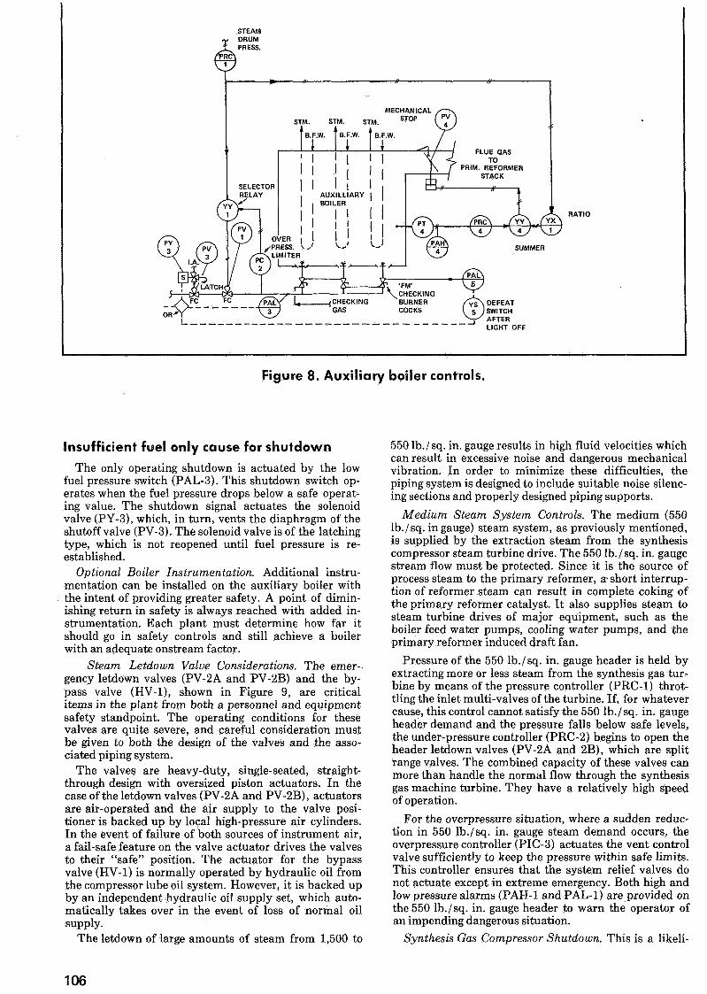
Steam Letdown Valve Considerations. The emer-gency letdown valves (PV-2A and PV-2B) and the by-pass valve (HV-1), shown in Figure 9, are criticalitems in the plant from both a personnel and equipmentsafety standpoint. The operating conditions for thesevalves are quite severe, and careful consideration mustbe given to both the design of the valves and the asso-ciated piping system.
The valves are heavy-duty, single-seated, straight-through design with oversized piston actuators. In thecase of the letdown valves (PV-2A and PV-2B), actuatorsare air-operated and the air supply to the valve posi-tioner is backed up by local high-pressure air cylinders.In the event of failure of both sources of instrument air,a fail-safe feature on the valve actuator drives the valvesto their "safe" position. The actuator for the bypassvalve (HV-1) is normally operated by hydraulic oil fromthe compressor lube oil system. However, it is backed upby an independent hydraulic oil supply set, which auto-matically takes over in the event of loss of normal oilsupply.
The letdown of large amounts of steam from 1,500 to
550 lb./sq. in. gauge results in high fluid velocities whichcan result in excessive noise and dangerous mechanicalvibration. In order to minimize these difficulties, thepiping system is designed to include suitable noise silenc-ing sections and properly designed piping supports.
Medium Steam System Controls. The medium (550lb./sq. in gauge) steam system, as previously mentioned,is supplied by the extraction steam from the synthesiscompressor steam turbine drive. The 550 lb./sq. in. gaugestream flow must be protected. Since it is the source ofprocess steam to the primary reformer, a- short interrup-tion of reformer steam can result in complete coking ofthe primary reformer catalyst. It also supplies steam tosteam turbine drives of major equipment, such as theboiler feed water pumps, cooling water pumps, and theprimary reformer induced draft fan.
Pressure of the 550 lb./sq. in. gauge header is held byextracting more or less steam from the synthesis gas tur-bine by means of the pressure controller (PRC-1) throt-tling the inlet multi-valves of the turbine. If, for whatevercause, this control cannot satisfy the 550 lb./sq. in. gaugeheader demand and the pressure falls below safe levels,the under-pressure controller (PRC-2) begins to open theheader letdown valves (PV-2A and 2B), which are splitrange valves. The combined capacity of these valves canmore than handle the normal flow through the synthesisgas machine turbine. They have a relatively high speedof operation.
For the overpressure situation, where a sudden reduc-tion in 550 lb./sq. in. gauge steam demand occurs, theoverpressure controller (PIC-3) actuates the vent controlvalve sufficiently to keep the pressure within safe limits.This controller ensures that the system relief valves donot actuate except in extreme emergency. Both high andlow pressure alarms (PAH-1 and PAL-1) are provided onthe 550 lb./sq. in. gauge header to warn the operator ofan impending dangerous situation.
Synthesis Gas Compressor Shutdown. This is a likeli-
106
1500 PSIG STEAM HEADER
REFORMERREFORMER PROCESSDRAFT FANTURBINE
BFVV PUMPTURBINE
COOLING WATERTURBINE
1 150 PSIG STEAM HEADER
Figure 9. Steam system.
hood during initial plant start-up, and it also may occurduring normal plant operation for various possible rea-sons. The compressor shutdown is effected by auto-matically or remote manually closing the 1,500 lb./sq. in.gauge steam shutoff valve (HV-2).
This process is quite rapid because the turbine inletvalve is hydraulically operated and set to close in lessthan one second. This quick closure results in an abruptstoppage of steam flowing to the 550 lb./sq. in. gaugeheader through the synthesis gas turbine, which must bereplaced immediately through the turbine bypass controlstation. The hydraulically-operated valve (HV-1) isopened by the same trip system that closes the com-pressor turbine inlet valve. The bypass valve (HV-1)trips wide open within one second so that only a verysmall and short duration dip in 550 lb./sq. in. gaugeheader pressure is experienced. The valve (HV-1) is sosized to pass somewhat less than the normal steam flowthrough the synthesis gas turbine, resulting in the pres-sure controller (PRC-2) automatically taking over con-trol of the header pressure and opening control valve(PRC-2A). Normal operating procedure next is to slowlyclose the synthesis gas bypass valve (HV-1), taking fullheader control utilizing both split range letdown valves(PRC-2A and 2B).
Conclusions
The safety controls outlined herewith represent aproven, adequate level of safety instrumentation to pro-vide a safe and operable plant during the majority ofemergency situations utilizing a minimum number of op-erating plant personnel.
Considerably more routine instrumentation must beprovided for less critical operating difficulties. Thesegenerally fall into the "housekeeping" variety of instru-mentation, such as compressor lube oil controls andalarms, high level alarms on process vessels, high temper-ature alarms on reactor walls, etc. Further, much moreinstrumentation is necessary for the normal process con-trol requirement. No attempt has been made to cover allinstrumentation requirements.
Great reliance is placed on plant operators to takeproper corrective action in response to alarm only de-vices. This requires well-trained, alert plant personnelwho thoroughly understand the plant operation and thecharacteristics of the plant equipment. There is no sub-stitute for qualified operators, if a plant is to operate
safely and have a good "onstream" record.The alarm devices described can be utilized to take
corrective action automatically. The amount of addi-tional instrumentation required to make logical correc-tive decisions and perform them in proper sequence tendsto become excessive. The increased number of compo-nents required brings up the question of reduced overallsystem reliability. It also increases the amount of pre-ventive maintenance necessary and generally the re-quired competence level of maintenance personnel. It isup to plant management to decide, based on knowledgeof plant personnel, the point of compromise where addi-tional safety instrumentation will be only marginallybeneficial to overall plant safety.
A final point should be made, and this with regard toinstrument systems maintenance. It is imperative that awell-planned preventive maintenance program be es-tablished at the onset of plant operation and adhered to.Maintenance personnel must be thoroughly familiar witheach safety loop from the standpoint of knowing its op-erating philosophy, the system "circuitry" and the char-acteristics of its hardware components. Only through thecoordination of personnel, major equipment, and safetyshutdown systems can one have an effective ammoniaplant safety system. #
A.M. Calabrese earned his B.S.Ch.E. fromC.C.N.Y. and later his M.S.Ch.E. fromBrooklyn Polytechnic Institute. He joined TheM.W. Kellogg Co. as an instrument engi-neer in 1956. Calabrese has been managerof instrument engineering at M. W. Kelloggsince 1965, having responsibility for allphases of process control system designand instrumentation.
L.D. Krejci, who earned his B.S.Ch.E. fifomIowa State University, is a senior instrumentengineer for The M.W. Kellogg Co. His as-signments have included control systems de-sign, construction engineering and start-upengineering on various petrochemical andnatural gas complexes, both domestic andforeign.
107