Embed Size (px)
Citation preview

an ISO 9001:2008 Registered Company
1970-81 Pontiac Firebird with Factory AirEvaporator Kit
(564150)
18865 Goll St. San Antonio, TX 78266 Phone: 210-654-7171
Fax: 210-654-3113www.vintageair.com
900111 REV D 10/07/15, PG 1 OF 28
2
www.vintageair.com
900111 REV D 10/07/15, PG 2 OF 28
Thank you for purchasing this evaporator kit from Vintage Air. When installing these components as part of a complete SureFit™ system, Vintage Air recommends working from front to back on the vehicle, installing the condenser kit, hose kit, and compressor first, followed by the wiring, evaporator, and finally the control panel.
Cover..................................................................................................................................Table of Contents.................................................................................................................Packing List/Parts Disclaimer..................................................................................................Information Page..................................................................................................................Wiring Notice.......................................................................................................................Engine Compartment Disassembly, Condenser Assembly and Installation, Compressor and Brackets.............................................................................................................................Engine Compartment Disassembly (Cont.)...............................................................................OEM Control Panel Removal...................................................................................................OEM Control Panel Removal (Cont.)........................................................................................Passenger Compartment Disassembly.................................................................................... Fresh Air Cap Installation, Heater Cover Assembly and Firewall Cover Installation.......................Heater Cover Assembly and Firewall Cover Installation (Cont.), Defrost Duct Installation.............Hose Adapter Installation.................................................................................................... Passenger Side Kick Panel and Fresh Air Cover Modification......................................................Kick Panel Fresh Air Cap Installation, Evaporator Installation.................................................... Evaporator Installation (Cont.)............................................................................................. Evaporator Installation (Final).............................................................................................. Drain Hose Installation, Lubricating O-rings, A/C Hose Installation............................................ Heater Hose & Heater Control Valve Installation, A/C and Heater Hose Routing.............................. Final Steps, Under Dash Hose Adapter Assembly Installation.................................................... Glove Box Installation, Driver Side Under Dash Cover Installation.............................................Control Panel & Duct Hose Routing........................................................................................ Wiring Diagram..................................................................................................................Gen IV Wiring Connection Instruction....................................................................................Operation of Controls..........................................................................................................Troubleshooting Guide.........................................................................................................Troubleshooting Guide (Cont.)..............................................................................................Packing List.......................................................................................................................
1 2 3 4 5
6 7 8 91011121314 1516171819202122232425262728
Table of Contents
3
www.vintageair.com
900111 REV D 10/07/15, PG 3 OF 28
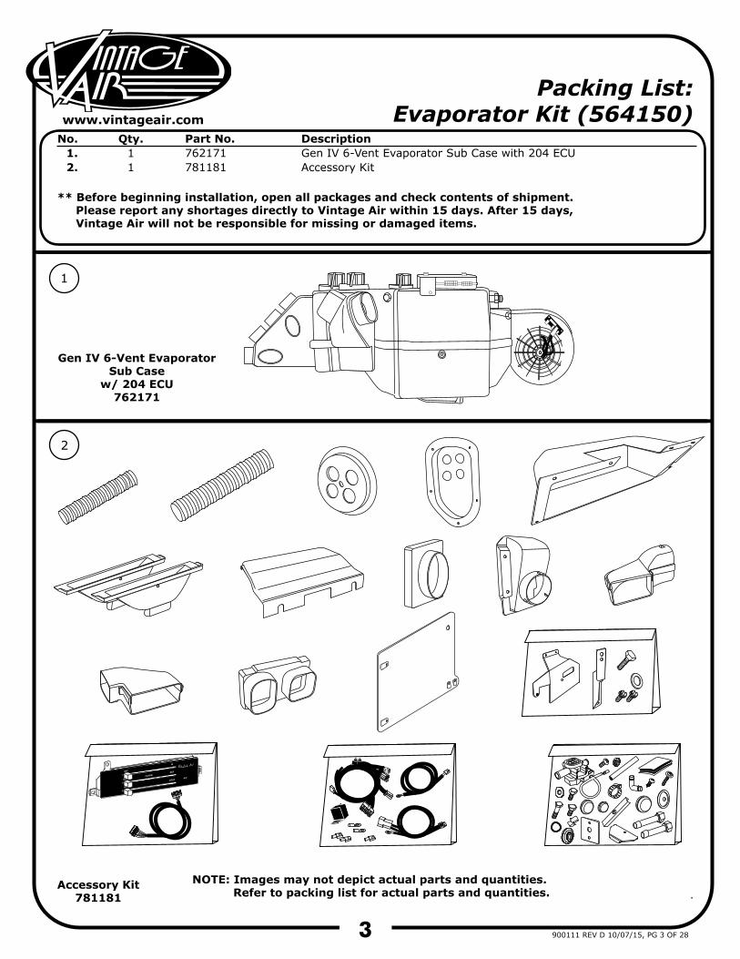
Packing List: Evaporator Kit (564150)
No. 1.2.
Qty.11
Part No.762171781181
DescriptionGen IV 6-Vent Evaporator Sub Case with 204 ECUAccessory Kit
** Before beginning installation, open all packages and check contents of shipment. Please report any shortages directly to Vintage Air within 15 days. After 15 days, Vintage Air will not be responsible for missing or damaged items.
NOTE: Images may not depict actual parts and quantities. Refer to packing list for actual parts and quantities.
1
2
Gen IV 6-Vent Evaporator Sub Case
w/ 204 ECU762171
Accessory Kit781181
4
www.vintageair.com
900111 REV D 10/07/15, PG 4 OF 28
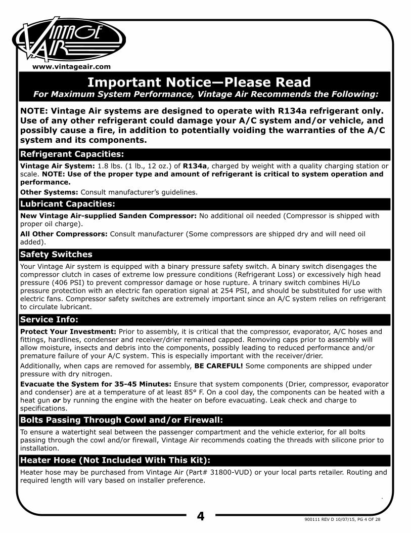
Important Notice—Please ReadFor Maximum System Performance, Vintage Air Recommends the Following:
New Vintage Air-supplied Sanden Compressor: No additional oil needed (Compressor is shipped with proper oil charge).All Other Compressors: Consult manufacturer (Some compressors are shipped dry and will need oil added).
NOTE: Vintage Air systems are designed to operate with R134a refrigerant only. Use of any other refrigerant could damage your A/C system and/or vehicle, and possibly cause a fire, in addition to potentially voiding the warranties of the A/C system and its components.
Refrigerant Capacities:Vintage Air System: 1.8 lbs. (1 lb., 12 oz.) of R134a, charged by weight with a quality charging station or scale. NOTE: Use of the proper type and amount of refrigerant is critical to system operation and performance.Other Systems: Consult manufacturer’s guidelines.
Lubricant Capacities:
Safety Switches
Service Info:Protect Your Investment: Prior to assembly, it is critical that the compressor, evaporator, A/C hoses and fittings, hardlines, condenser and receiver/drier remained capped. Removing caps prior to assembly will allow moisture, insects and debris into the components, possibly leading to reduced performance and/or premature failure of your A/C system. This is especially important with the receiver/drier. Additionally, when caps are removed for assembly, BE CAREFUL! Some components are shipped under pressure with dry nitrogen.Evacuate the System for 35-45 Minutes: Ensure that system components (Drier, compressor, evaporator and condenser) are at a temperature of at least 85° F. On a cool day, the components can be heated with a heat gun or by running the engine with the heater on before evacuating. Leak check and charge to specifications.
Your Vintage Air system is equipped with a binary pressure safety switch. A binary switch disengages the compressor clutch in cases of extreme low pressure conditions (Refrigerant Loss) or excessively high head pressure (406 PSI) to prevent compressor damage or hose rupture. A trinary switch combines Hi/Lo pressure protection with an electric fan operation signal at 254 PSI, and should be substituted for use with electric fans. Compressor safety switches are extremely important since an A/C system relies on refrigerant to circulate lubricant.
Bolts Passing Through Cowl and/or Firewall:To ensure a watertight seal between the passenger compartment and the vehicle exterior, for all bolts passing through the cowl and/or firewall, Vintage Air recommends coating the threads with silicone prior to installation.
Heater Hose (Not Included With This Kit):Heater hose may be purchased from Vintage Air (Part# 31800-VUD) or your local parts retailer. Routing and required length will vary based on installer preference.
5
www.vintageair.com
900111 REV D 10/07/15, PG 5 OF 28
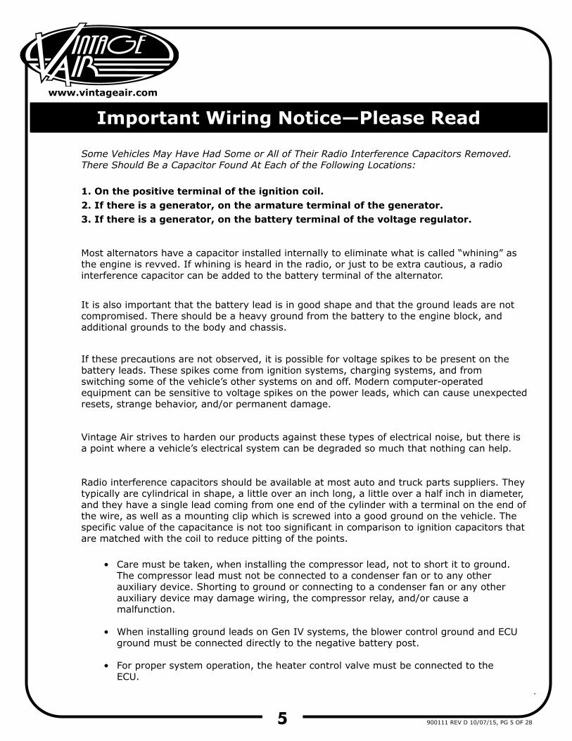
Important Wiring Notice—Please Read
Some Vehicles May Have Had Some or All of Their Radio Interference Capacitors Removed. There Should Be a Capacitor Found At Each of the Following Locations:
1. On the positive terminal of the ignition coil.2. If there is a generator, on the armature terminal of the generator.3. If there is a generator, on the battery terminal of the voltage regulator.
Most alternators have a capacitor installed internally to eliminate what is called “whining” as the engine is revved. If whining is heard in the radio, or just to be extra cautious, a radio interference capacitor can be added to the battery terminal of the alternator.
It is also important that the battery lead is in good shape and that the ground leads are not compromised. There should be a heavy ground from the battery to the engine block, and additional grounds to the body and chassis.
If these precautions are not observed, it is possible for voltage spikes to be present on the battery leads. These spikes come from ignition systems, charging systems, and from switching some of the vehicle’s other systems on and off. Modern computer-operated equipment can be sensitive to voltage spikes on the power leads, which can cause unexpected resets, strange behavior, and/or permanent damage.
Vintage Air strives to harden our products against these types of electrical noise, but there is a point where a vehicle’s electrical system can be degraded so much that nothing can help.
Radio interference capacitors should be available at most auto and truck parts suppliers. They typically are cylindrical in shape, a little over an inch long, a little over a half inch in diameter, and they have a single lead coming from one end of the cylinder with a terminal on the end of the wire, as well as a mounting clip which is screwed into a good ground on the vehicle. The specific value of the capacitance is not too significant in comparison to ignition capacitors that are matched with the coil to reduce pitting of the points.
Care must be taken, when installing the compressor lead, not to short it to ground. The compressor lead must not be connected to a condenser fan or to any other auxiliary device. Shorting to ground or connecting to a condenser fan or any other auxiliary device may damage wiring, the compressor relay, and/or cause a malfunction.
When installing ground leads on Gen IV systems, the blower control ground and ECU ground must be connected directly to the negative battery post.
For proper system operation, the heater control valve must be connected to the ECU.
•
•
•
6
www.vintageair.com
900111 REV D 10/07/15, PG 6 OF 28
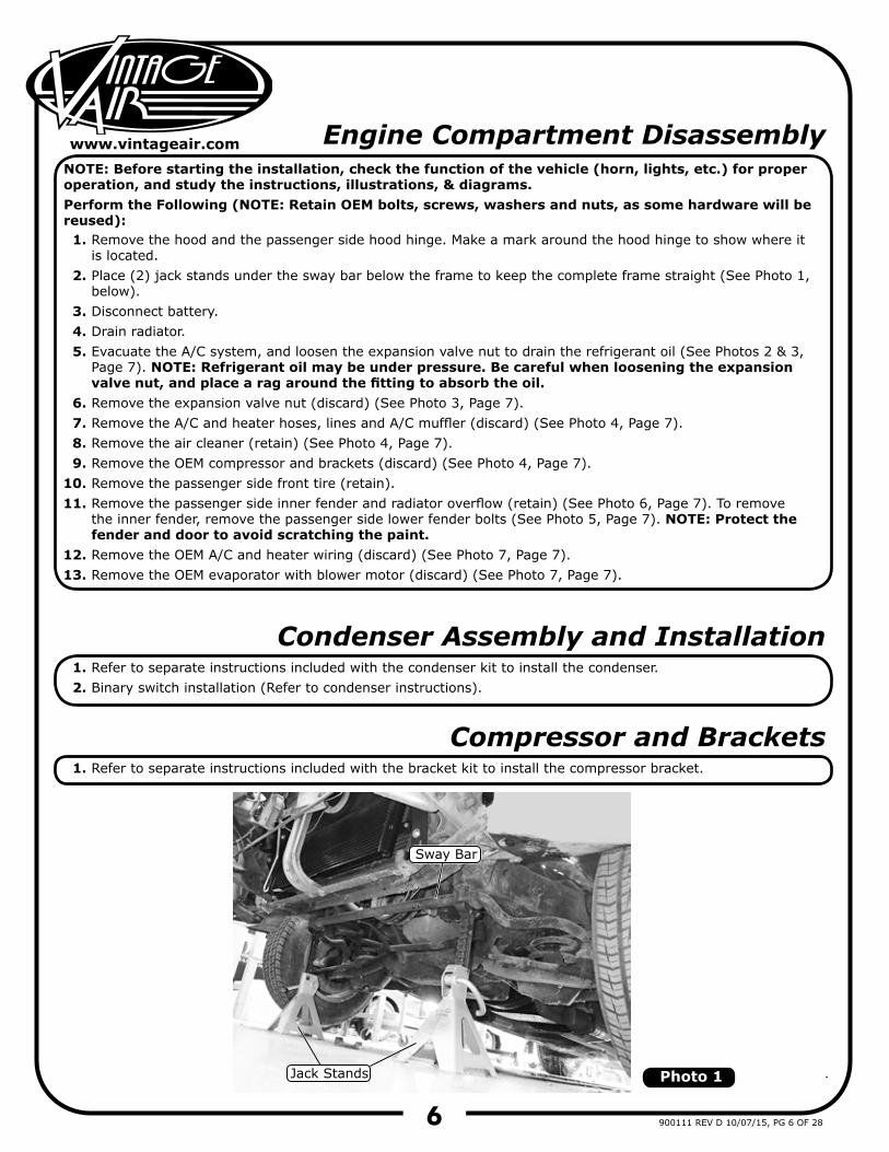
Engine Compartment Disassembly
1.
2.
3.4.5.
6.7.8.9.
10.11.
12.13.
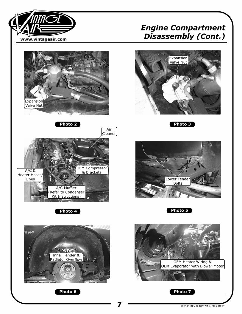
Remove the hood and the passenger side hood hinge. Make a mark around the hood hinge to show where it is located.Place (2) jack stands under the sway bar below the frame to keep the complete frame straight (See Photo 1, below).Disconnect battery.Drain radiator.Evacuate the A/C system, and loosen the expansion valve nut to drain the refrigerant oil (See Photos 2 & 3, Page 7). NOTE: Refrigerant oil may be under pressure. Be careful when loosening the expansion valve nut, and place a rag around the fitting to absorb the oil.Remove the expansion valve nut (discard) (See Photo 3, Page 7).Remove the A/C and heater hoses, lines and A/C muffler (discard) (See Photo 4, Page 7).Remove the air cleaner (retain) (See Photo 4, Page 7).Remove the OEM compressor and brackets (discard) (See Photo 4, Page 7).Remove the passenger side front tire (retain).Remove the passenger side inner fender and radiator overflow (retain) (See Photo 6, Page 7). To remove the inner fender, remove the passenger side lower fender bolts (See Photo 5, Page 7). NOTE: Protect the fender and door to avoid scratching the paint.Remove the OEM A/C and heater wiring (discard) (See Photo 7, Page 7).Remove the OEM evaporator with blower motor (discard) (See Photo 7, Page 7).
NOTE: Before starting the installation, check the function of the vehicle (horn, lights, etc.) for proper operation, and study the instructions, illustrations, & diagrams.Perform the Following (NOTE: Retain OEM bolts, screws, washers and nuts, as some hardware will be reused):
Condenser Assembly and Installation1.2.
Refer to separate instructions included with the condenser kit to install the condenser.Binary switch installation (Refer to condenser instructions).
Compressor and Brackets1. Refer to separate instructions included with the bracket kit to install the compressor bracket.
Photo 1Jack Stands
Sway Bar
7
www.vintageair.com
900111 REV D 10/07/15, PG 7 OF 28
Engine CompartmentDisassembly (Cont.)
Photo 2
Photo 4
Photo 6 Photo 7
Photo 5
Photo 3
ExpansionValve Nut
OEM Heater Wiring &OEM Evaporator with Blower Motor
Inner Fender & Radiator Overflow
Lower FenderBolts
AirCleaner
ExpansionValve Nut
A/C &Heater Hoses/
Lines
OEM Compressor& Brackets
A/C Muffler(Refer to Condenser
Kit Instructions)
8
www.vintageair.com
900111 REV D 10/07/15, PG 8 OF 28
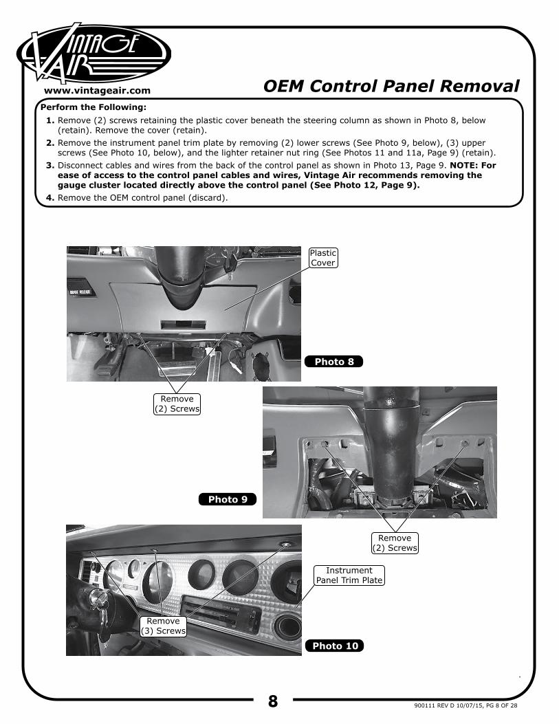
OEM Control Panel Removal
1.
2.
3.
4.
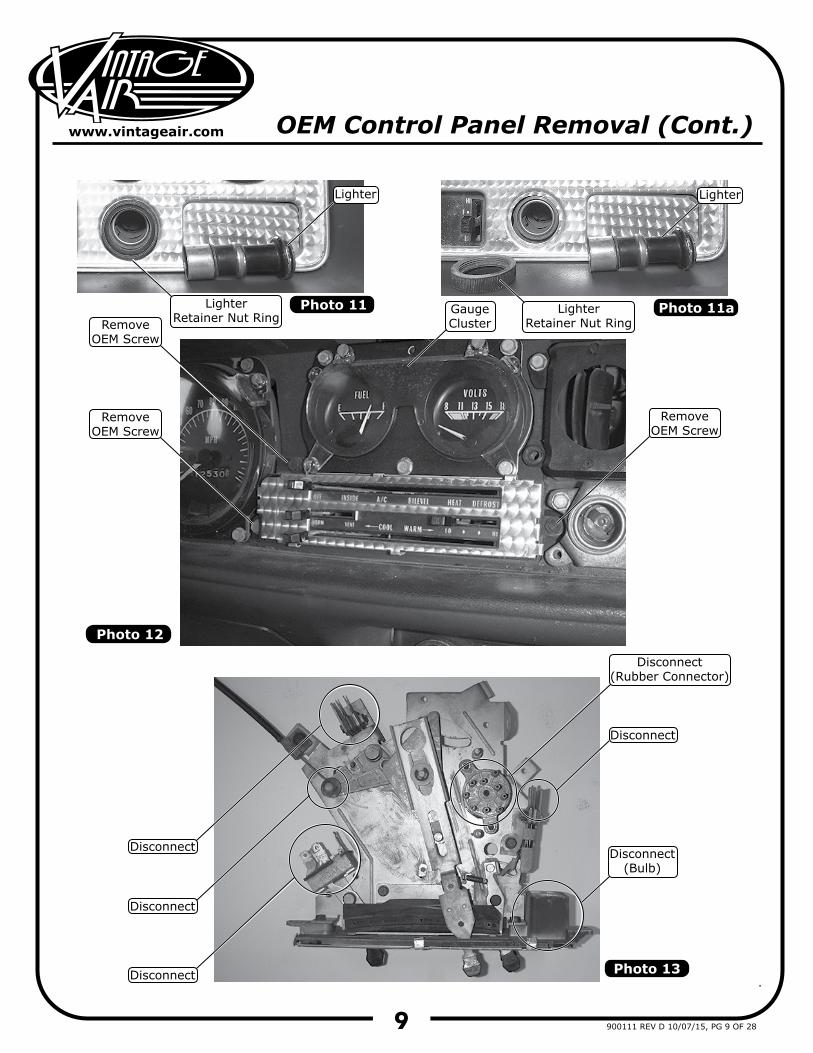
Remove (2) screws retaining the plastic cover beneath the steering column as shown in Photo 8, below (retain). Remove the cover (retain).Remove the instrument panel trim plate by removing (2) lower screws (See Photo 9, below), (3) upper screws (See Photo 10, below), and the lighter retainer nut ring (See Photos 11 and 11a, Page 9) (retain).Disconnect cables and wires from the back of the control panel as shown in Photo 13, Page 9. NOTE: For ease of access to the control panel cables and wires, Vintage Air recommends removing the gauge cluster located directly above the control panel (See Photo 12, Page 9).Remove the OEM control panel (discard).
Perform the Following:
Photo 8
Photo 9
Photo 10
Remove(2) Screws
Remove(2) Screws
PlasticCover
Remove(3) Screws
InstrumentPanel Trim Plate
9
www.vintageair.com
900111 REV D 10/07/15, PG 9 OF 28
OEM Control Panel Removal (Cont.)
Photo 12
Photo 13
Disconnect(Rubber Connector)
RemoveOEM Screw
RemoveOEM Screw
RemoveOEM Screw
Photo 11LighterRetainer Nut Ring
LighterRetainer Nut Ring
Photo 11a
LighterLighter
GaugeCluster
Disconnect(Bulb)
Disconnect
Disconnect
Disconnect
Disconnect
10
www.vintageair.com
900111 REV D 10/07/15, PG 10 OF 28
Passenger Compartment Disassembly
1.2.3.4.
5.6.7.
8.
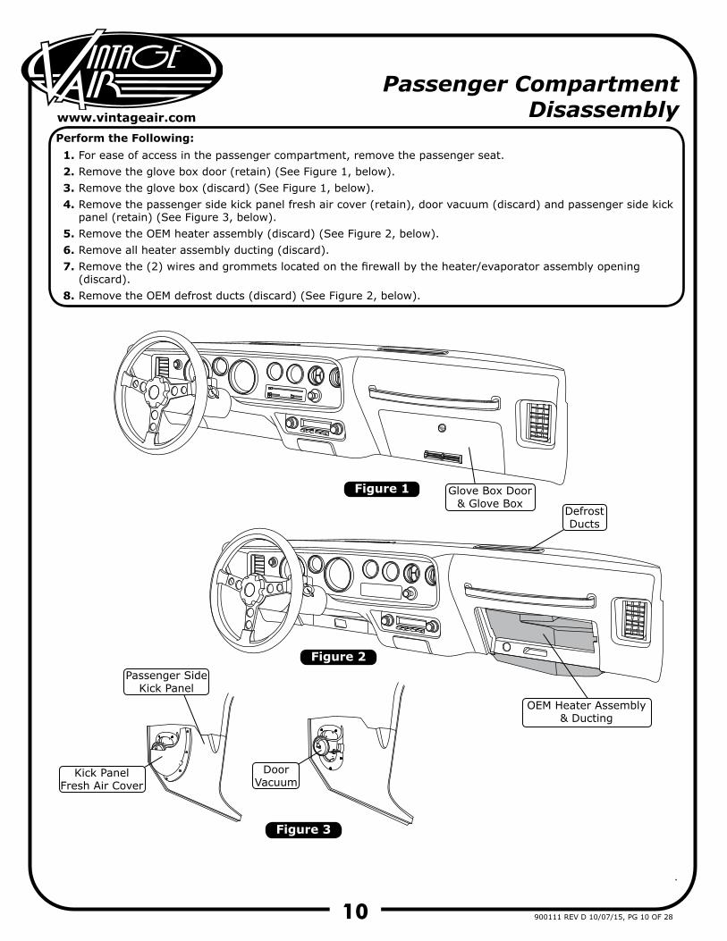
For ease of access in the passenger compartment, remove the passenger seat.Remove the glove box door (retain) (See Figure 1, below).Remove the glove box (discard) (See Figure 1, below).Remove the passenger side kick panel fresh air cover (retain), door vacuum (discard) and passenger side kick panel (retain) (See Figure 3, below).Remove the OEM heater assembly (discard) (See Figure 2, below).Remove all heater assembly ducting (discard).Remove the (2) wires and grommets located on the firewall by the heater/evaporator assembly opening (discard).Remove the OEM defrost ducts (discard) (See Figure 2, below).
Perform the Following:
Figure 1
Figure 2
Figure 3
OEM Heater Assembly & Ducting
Glove Box Door& Glove Box
Passenger SideKick Panel
Kick PanelFresh Air Cover
DoorVacuum
DefrostDucts
11
www.vintageair.com
900111 REV D 10/07/15, PG 11 OF 28
Figure 4
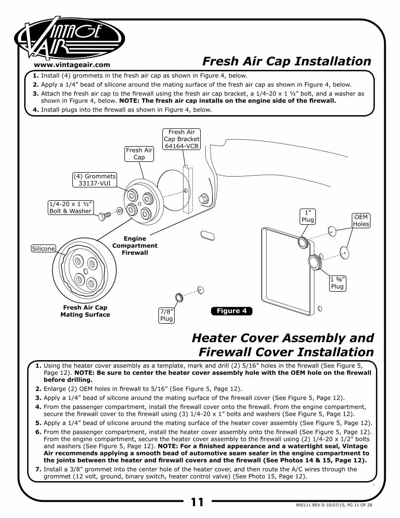
Fresh Air Cap Installation
Heater Cover Assembly and Firewall Cover Installation
1.2.3.
4.
1.
2.3.4.
5.6.
7.
Install (4) grommets in the fresh air cap as shown in Figure 4, below.Apply a 1/4” bead of silicone around the mating surface of the fresh air cap as shown in Figure 4, below.Attach the fresh air cap to the firewall using the fresh air cap bracket, a 1/4-20 x 1 ½” bolt, and a washer as shown in Figure 4, below. NOTE: The fresh air cap installs on the engine side of the firewall.Install plugs into the firewall as shown in Figure 4, below.
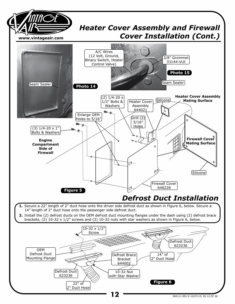
Using the heater cover assembly as a template, mark and drill (2) 5/16” holes in the firewall (See Figure 5, Page 12). NOTE: Be sure to center the heater cover assembly hole with the OEM hole on the firewall before drilling.Enlarge (2) OEM holes in firewall to 5/16” (See Figure 5, Page 12).Apply a 1/4” bead of silicone around the mating surface of the firewall cover (See Figure 5, Page 12).From the passenger compartment, install the firewall cover onto the firewall. From the engine compartment, secure the firewall cover to the firewall using (3) 1/4-20 x 1” bolts and washers (See Figure 5, Page 12).Apply a 1/4” bead of silicone around the mating surface of the heater cover assembly (See Figure 5, Page 12).From the passenger compartment, install the heater cover assembly onto the firewall (See Figure 5, Page 12). From the engine compartment, secure the heater cover assembly to the firewall using (2) 1/4-20 x 1/2” bolts and washers (See Figure 5, Page 12). NOTE: For a finished appearance and a watertight seal, Vintage Air recommends applying a smooth bead of automotive seam sealer in the engine compartment to the joints between the heater and firewall covers and the firewall (See Photos 14 & 15, Page 12).Install a 3/8” grommet into the center hole of the heater cover, and then route the A/C wires through the grommet (12 volt, ground, binary switch, heater control valve) (See Photo 15, Page 12).
(4) Grommets33137-VUI
Fresh AirCap
Fresh AirCap Bracket64164-VCB
Fresh Air CapMating Surface
EngineCompartment
FirewallSilicone
7/8”Plug
1”Plug
1 ⅝”Plug
OEMHoles
1/4-20 x 1 ½”Bolt & Washer
12
www.vintageair.com
900111 REV D 10/07/15, PG 12 OF 28
Defrost Duct Installation1.
2.
Secure a 22” length of 2” duct hose onto the driver side defrost duct as shown in Figure 6, below. Secure a 14” length of 2” duct hose onto the passenger side defrost duct.Install the (2) defrost ducts on the OEM defrost duct mounting flanges under the dash using (2) defrost brace brackets, (2) 10-32 x 1/2” screws and (2) 10-32 nuts with star washers as shown in Figure 6, below.
Figure 6
OEMDefrost Duct
Mounting Flange14” of
2” Duct Hose
22” of2” Duct Hose
Defrost BraceBracket644002
Defrost Duct623236
Defrost Duct623236
10-32 x 1/2”Screw
10-32 Nutwith Star Washer
Photo 14
Photo 15
Heater Cover Assembly and Firewall Cover Installation (Cont.)
Figure 5
Heater Cover AssemblyMating Surface
Firewall CoverMating Surface
EngineCompartment
Side ofFirewall
Silicone
Silicone
(3) 1/4-20 x 1”Bolts & Washers
(2) 1/4-20 x1/2” Bolts &
WashersHeater Cover
Assembly644021
Firewall Cover648228
Seam Sealer
Enlarge OEMHoles to 5/16” Drill (2)
5/16”Holes
Seam Sealer
3/8” Grommet33144-VUI
A/C Wires(12 Volt, Ground,
Binary Switch, Heater Control Valve)
13
www.vintageair.com
900111 REV D 10/07/15, PG 13 OF 28
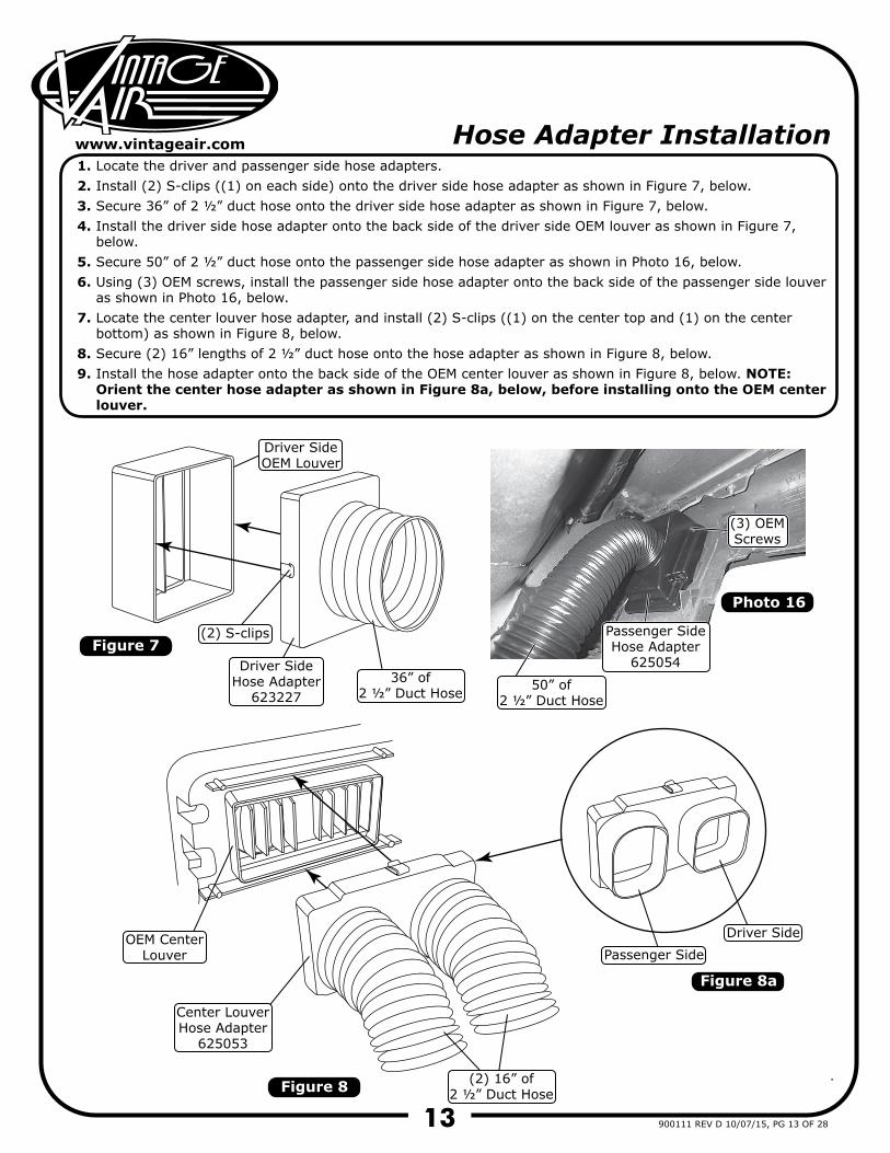
Hose Adapter Installation1.2.3.4.
5.6.
7.
8.9.
Locate the driver and passenger side hose adapters.Install (2) S-clips ((1) on each side) onto the driver side hose adapter as shown in Figure 7, below.Secure 36” of 2 ½” duct hose onto the driver side hose adapter as shown in Figure 7, below.Install the driver side hose adapter onto the back side of the driver side OEM louver as shown in Figure 7, below.Secure 50” of 2 ½” duct hose onto the passenger side hose adapter as shown in Photo 16, below.Using (3) OEM screws, install the passenger side hose adapter onto the back side of the passenger side louver as shown in Photo 16, below.Locate the center louver hose adapter, and install (2) S-clips ((1) on the center top and (1) on the center bottom) as shown in Figure 8, below.Secure (2) 16” lengths of 2 ½” duct hose onto the hose adapter as shown in Figure 8, below.Install the hose adapter onto the back side of the OEM center louver as shown in Figure 8, below. NOTE: Orient the center hose adapter as shown in Figure 8a, below, before installing onto the OEM center louver.
Figure 7
Figure 8
Figure 8a
(3) OEMScrews
Passenger SideHose Adapter
625054
Driver SideOEM Louver
OEM Center Louver
Driver SideHose Adapter
623227
Center LouverHose Adapter
625053
Driver SidePassenger Side
(2) S-clips
36” of2 ½” Duct Hose 50” of
2 ½” Duct Hose
(2) 16” of2 ½” Duct Hose
Photo 16
14
www.vintageair.com
900111 REV D 10/07/15, PG 14 OF 28
Figure 9
Figure 10
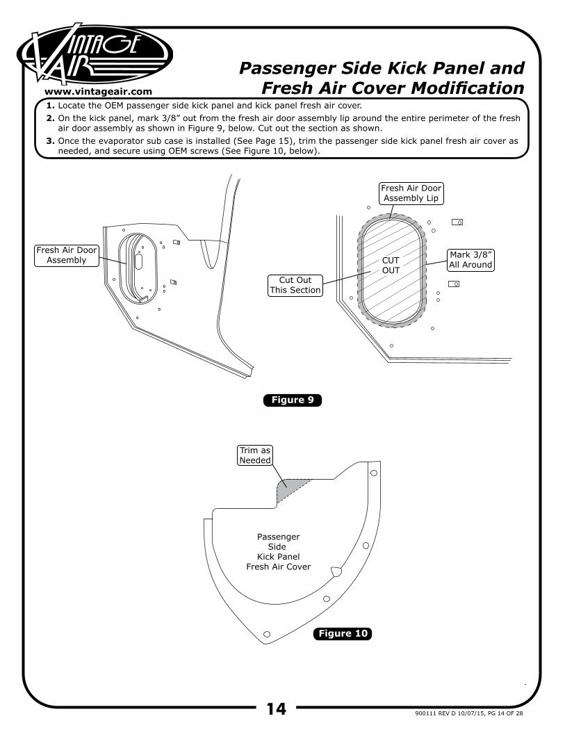
Passenger Side Kick Panel andFresh Air Cover Modification
1.2.
3.
Locate the OEM passenger side kick panel and kick panel fresh air cover.On the kick panel, mark 3/8” out from the fresh air door assembly lip around the entire perimeter of the fresh air door assembly as shown in Figure 9, below. Cut out the section as shown.Once the evaporator sub case is installed (See Page 15), trim the passenger side kick panel fresh air cover as needed, and secure using OEM screws (See Figure 10, below).
CUTOUT
PassengerSide
Kick PanelFresh Air Cover
Fresh Air DoorAssembly
Fresh Air DoorAssembly Lip
Cut OutThis Section
Trim asNeeded
Mark 3/8”All Around
15
www.vintageair.com
900111 REV D 10/07/15, PG 15 OF 28
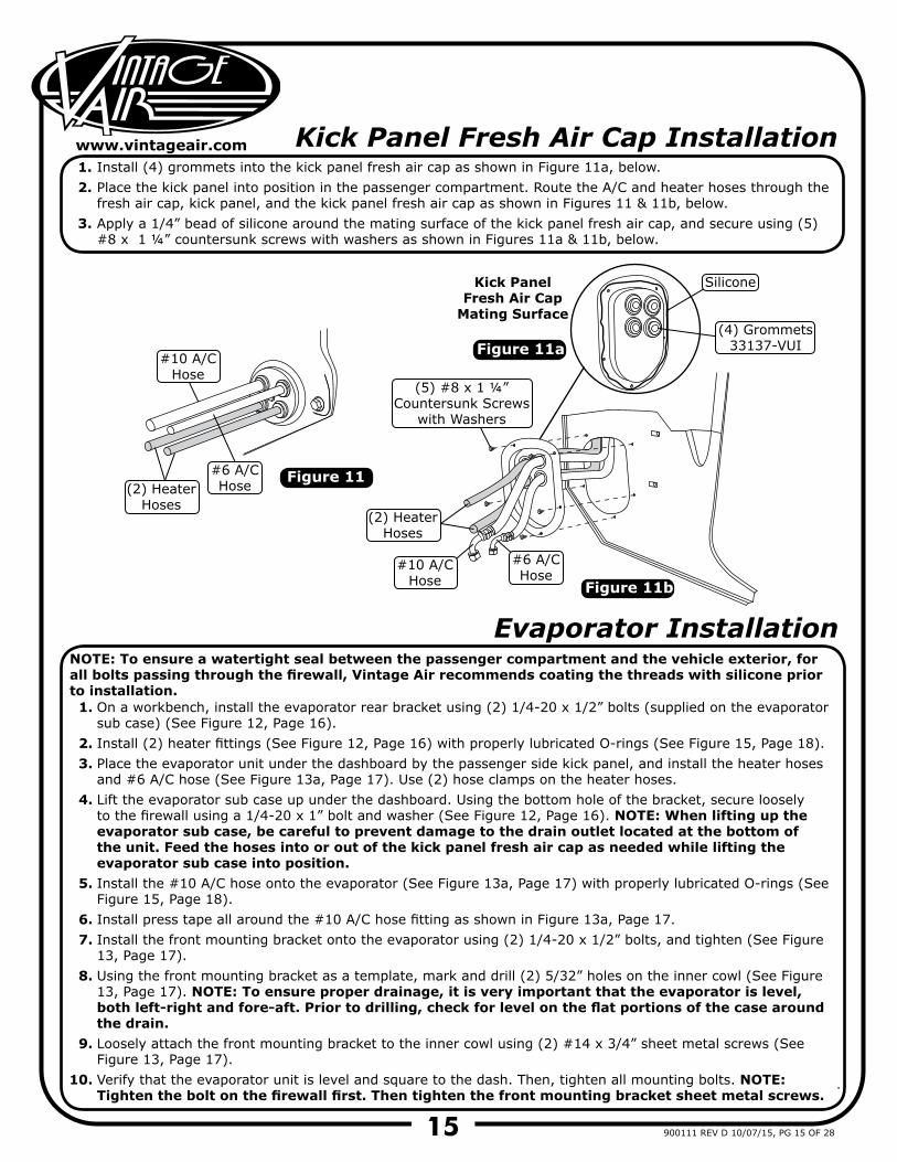
Kick Panel Fresh Air Cap Installation1.2.
3.
Install (4) grommets into the kick panel fresh air cap as shown in Figure 11a, below.Place the kick panel into position in the passenger compartment. Route the A/C and heater hoses through the fresh air cap, kick panel, and the kick panel fresh air cap as shown in Figures 11 & 11b, below. Apply a 1/4” bead of silicone around the mating surface of the kick panel fresh air cap, and secure using (5) #8 x 1 ¼” countersunk screws with washers as shown in Figures 11a & 11b, below.
Figure 11
Figure 11a
Figure 11b
Evaporator Installation
1.
2.3.
4.
5.
6.7.
8.
9.
10.
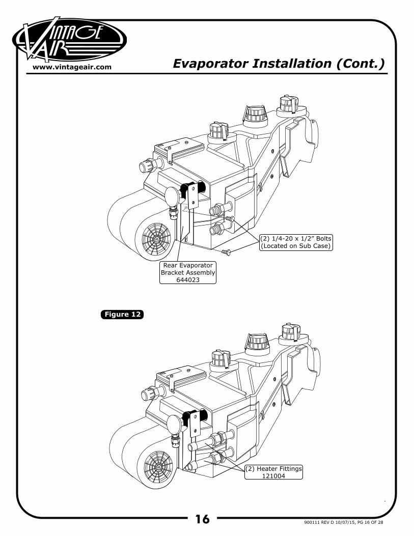
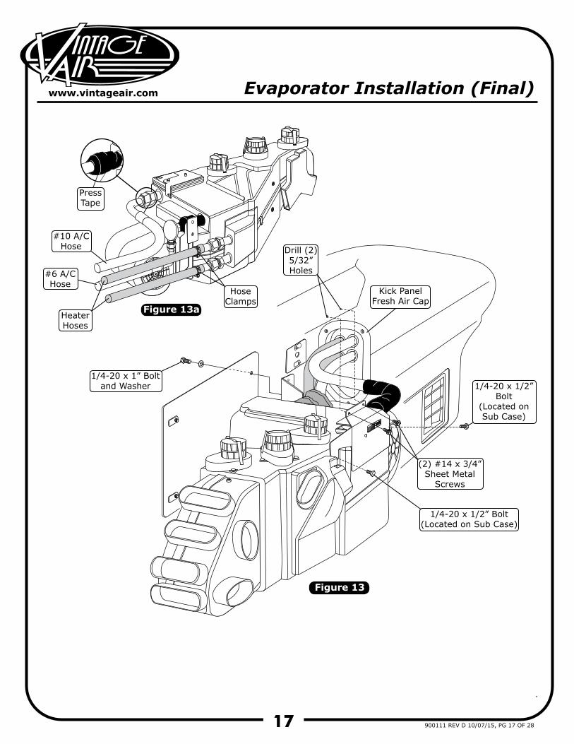
On a workbench, install the evaporator rear bracket using (2) 1/4-20 x 1/2” bolts (supplied on the evaporator sub case) (See Figure 12, Page 16).Install (2) heater fittings (See Figure 12, Page 16) with properly lubricated O-rings (See Figure 15, Page 18).Place the evaporator unit under the dashboard by the passenger side kick panel, and install the heater hoses and #6 A/C hose (See Figure 13a, Page 17). Use (2) hose clamps on the heater hoses.Lift the evaporator sub case up under the dashboard. Using the bottom hole of the bracket, secure loosely to the firewall using a 1/4-20 x 1” bolt and washer (See Figure 12, Page 16). NOTE: When lifting up the evaporator sub case, be careful to prevent damage to the drain outlet located at the bottom of the unit. Feed the hoses into or out of the kick panel fresh air cap as needed while lifting the evaporator sub case into position.Install the #10 A/C hose onto the evaporator (See Figure 13a, Page 17) with properly lubricated O-rings (See Figure 15, Page 18).Install press tape all around the #10 A/C hose fitting as shown in Figure 13a, Page 17.Install the front mounting bracket onto the evaporator using (2) 1/4-20 x 1/2” bolts, and tighten (See Figure 13, Page 17).Using the front mounting bracket as a template, mark and drill (2) 5/32” holes on the inner cowl (See Figure 13, Page 17). NOTE: To ensure proper drainage, it is very important that the evaporator is level, both left-right and fore-aft. Prior to drilling, check for level on the flat portions of the case around the drain.Loosely attach the front mounting bracket to the inner cowl using (2) #14 x 3/4” sheet metal screws (See Figure 13, Page 17).Verify that the evaporator unit is level and square to the dash. Then, tighten all mounting bolts. NOTE: Tighten the bolt on the firewall first. Then tighten the front mounting bracket sheet metal screws.
NOTE: To ensure a watertight seal between the passenger compartment and the vehicle exterior, for all bolts passing through the firewall, Vintage Air recommends coating the threads with silicone prior to installation.
#10 A/CHose
#10 A/CHose
Silicone
(2) HeaterHoses
(2) HeaterHoses
#6 A/CHose
#6 A/CHose
Kick PanelFresh Air Cap
Mating Surface(4) Grommets
33137-VUI
(5) #8 x 1 ¼”Countersunk Screws
with Washers
16
www.vintageair.com
900111 REV D 10/07/15, PG 16 OF 28
Figure 12
Evaporator Installation (Cont.)
Rear Evaporator Bracket Assembly
644023
(2) Heater Fittings121004
(2) 1/4-20 x 1/2” Bolts(Located on Sub Case)
17
www.vintageair.com
900111 REV D 10/07/15, PG 17 OF 28
Figure 13
Figure 13a
Evaporator Installation (Final)
1/4-20 x 1” Boltand Washer
(2) #14 x 3/4”Sheet Metal
Screws
Kick PanelFresh Air Cap
#10 A/CHose
PressTape
HeaterHoses
HoseClamps
#6 A/CHose
Drill (2) 5/32”Holes
1/4-20 x 1/2” Bolt(Located on Sub Case)
1/4-20 x 1/2”Bolt
(Located onSub Case)
18
www.vintageair.com
900111 REV D 10/07/15, PG 18 OF 28
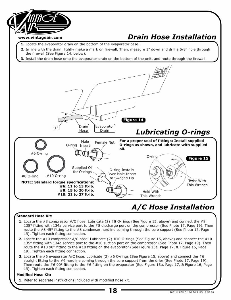
Drain Hose Installation1.2.
3.
Locate the evaporator drain on the bottom of the evaporator case.In line with the drain, lightly make a mark on firewall. Then, measure 1” down and drill a 5/8” hole through the firewall (See Figure 14, below).Install the drain hose onto the evaporator drain on the bottom of the unit, and route through the firewall.
Figure 14
A/C Hose Installation
1.
2.
3.
Locate the #8 compressor A/C hose. Lubricate (2) #8 O-rings (See Figure 15, above) and connect the #8 135° fitting with 134a service port to the #8 discharge port on the compressor (See Photo 17, Page 19). Then route the #8 45° fitting to the #8 condenser hardline coming through the core support (See Photo 17, Page 19). Tighten each fitting connection.Locate the #10 compressor A/C hose. Lubricate (2) #10 O-rings (See Figure 15, above) and connect the #10 135° fitting with 134a service port to the #10 suction port on the compressor (See Photo 17, Page 19). Then route the #10 90° fitting to the #10 fitting on the evaporator (See Figure 13a, Page 17, & Figure 16, Page 19). Tighten each fitting connection.Locate the #6 evaporator A/C hose. Lubricate (2) #6 O-rings (See Figure 15, above) and connect the #6 straight fitting to the #6 hardline coming through the core support from the drier (See Photo 17, Page 19). Then route the #6 90° fitting to the #6 fitting on the evaporator (See Figure 13a, Page 17, & Figure 16, Page 19). Tighten each fitting connection.
Standard Hose Kit:
1. Refer to separate instructions included with modified hose kit.Modified Hose Kit:
Figure ##
O-ring Installs Over Male Insert to Swaged Lip
O-ring#6 O-ring
#8 O-ring #10 O-ring
O-ring
Supplied Oil for O-rings
Male Insert
Female Nut
Hold With This Wrench
Twist With This Wrench
Lubricating O-rings For a proper seal of fittings: Install supplied O-rings as shown, and lubricate with supplied oil.
NOTE: Standard torque specifications:#6: 11 to 13 ft-lb.#8: 15 to 20 ft-lb.
#10: 21 to 27 ft-lb.
Figure 15
EvaporatorDrain
DrainHose
1”
19
www.vintageair.com
900111 REV D 10/07/15, PG 19 OF 28
Figure 16
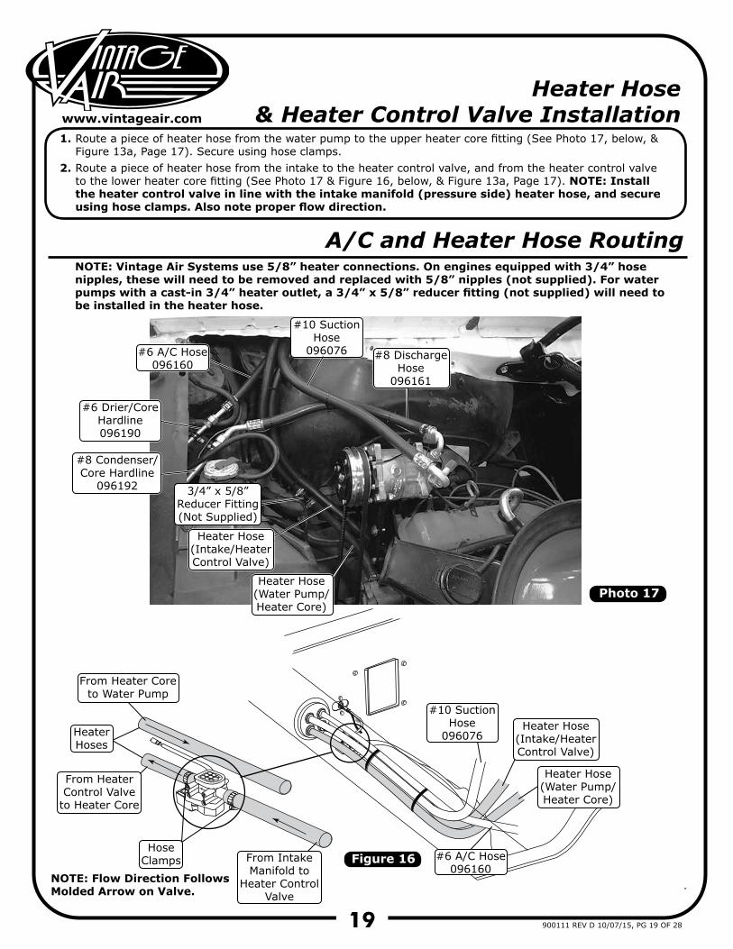
Heater Hose & Heater Control Valve Installation
1.
2.
Route a piece of heater hose from the water pump to the upper heater core fitting (See Photo 17, below, & Figure 13a, Page 17). Secure using hose clamps.Route a piece of heater hose from the intake to the heater control valve, and from the heater control valve to the lower heater core fitting (See Photo 17 & Figure 16, below, & Figure 13a, Page 17). NOTE: Install the heater control valve in line with the intake manifold (pressure side) heater hose, and secure using hose clamps. Also note proper flow direction.
Photo 17
A/C and Heater Hose Routing
Heater Hose(Intake/HeaterControl Valve)
#8 DischargeHose
096161
#6 A/C Hose096160
#6 A/C Hose096160
#10 SuctionHose
096076
#10 SuctionHose
096076
HoseClamps
From HeaterControl Valve
to Heater Core
From IntakeManifold to
Heater ControlValve
From Heater Coreto Water Pump
Heater Hose(Water Pump/Heater Core)
Heater Hose(Water Pump/Heater Core)
#6 Drier/CoreHardline096190
#8 Condenser/Core Hardline
096192
HeaterHoses
Heater Hose(Intake/HeaterControl Valve)
NOTE: Flow Direction Follows Molded Arrow on Valve.
NOTE: Vintage Air Systems use 5/8” heater connections. On engines equipped with 3/4” hose nipples, these will need to be removed and replaced with 5/8” nipples (not supplied). For water pumps with a cast-in 3/4” heater outlet, a 3/4” x 5/8” reducer fitting (not supplied) will need to be installed in the heater hose.
3/4” x 5/8”Reducer Fitting(Not Supplied)
20
www.vintageair.com
900111 REV D 10/07/15, PG 20 OF 28
Figure 17
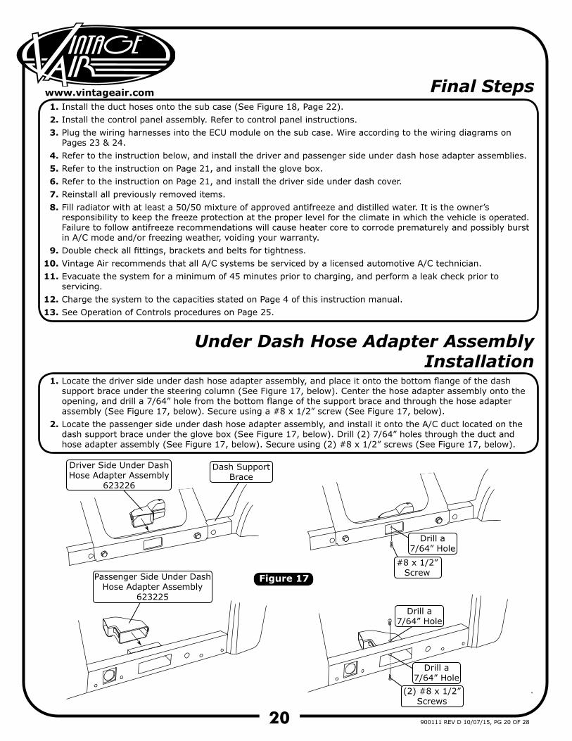
Under Dash Hose Adapter Assembly Installation
1.
2.
Locate the driver side under dash hose adapter assembly, and place it onto the bottom flange of the dash support brace under the steering column (See Figure 17, below). Center the hose adapter assembly onto the opening, and drill a 7/64” hole from the bottom flange of the support brace and through the hose adapter assembly (See Figure 17, below). Secure using a #8 x 1/2” screw (See Figure 17, below).Locate the passenger side under dash hose adapter assembly, and install it onto the A/C duct located on the dash support brace under the glove box (See Figure 17, below). Drill (2) 7/64” holes through the duct and hose adapter assembly (See Figure 17, below). Secure using (2) #8 x 1/2” screws (See Figure 17, below).
Final Steps1.2.3.
4.5.6.7.8.
9.10.11.
12.13.
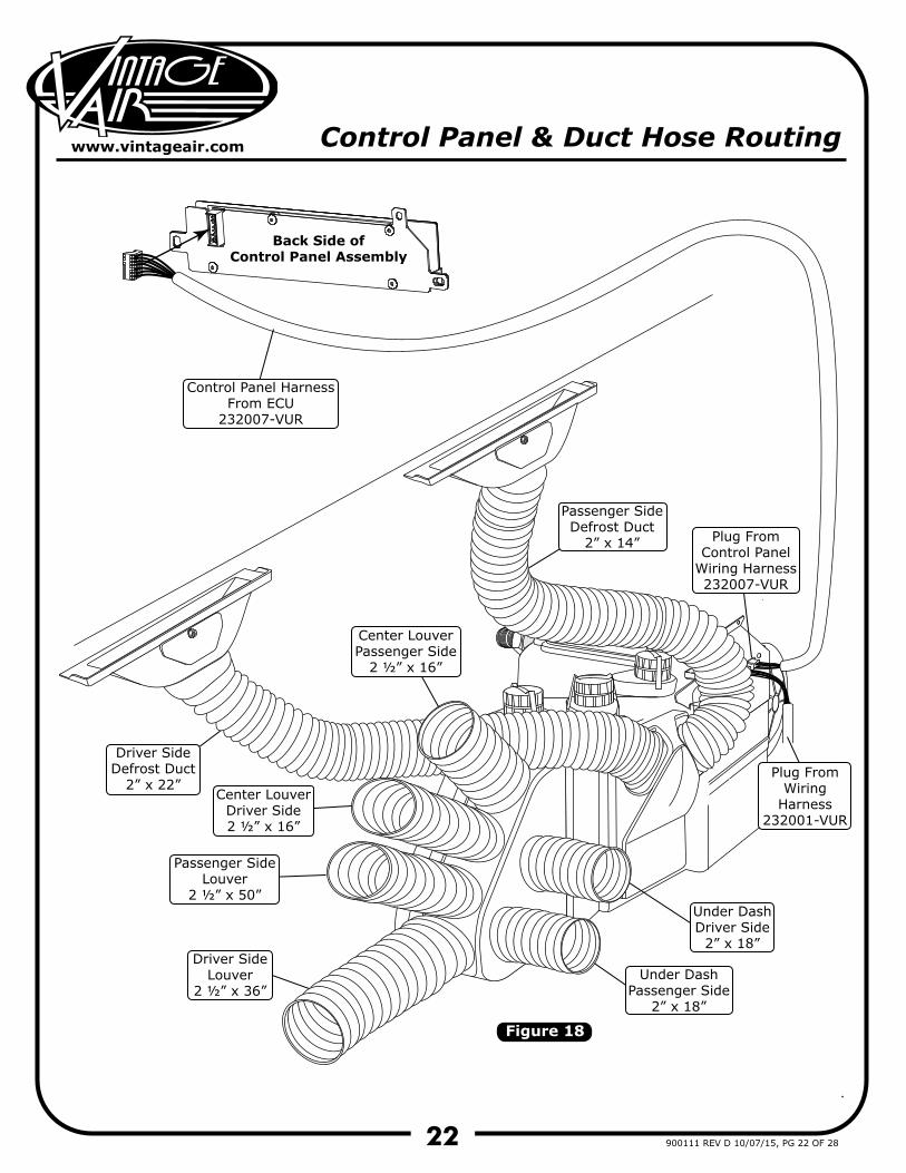
Install the duct hoses onto the sub case (See Figure 18, Page 22).Install the control panel assembly. Refer to control panel instructions.Plug the wiring harnesses into the ECU module on the sub case. Wire according to the wiring diagrams on Pages 23 & 24.Refer to the instruction below, and install the driver and passenger side under dash hose adapter assemblies.Refer to the instruction on Page 21, and install the glove box.Refer to the instruction on Page 21, and install the driver side under dash cover.Reinstall all previously removed items.Fill radiator with at least a 50/50 mixture of approved antifreeze and distilled water. It is the owner’s responsibility to keep the freeze protection at the proper level for the climate in which the vehicle is operated. Failure to follow antifreeze recommendations will cause heater core to corrode prematurely and possibly burst in A/C mode and/or freezing weather, voiding your warranty.Double check all fittings, brackets and belts for tightness.Vintage Air recommends that all A/C systems be serviced by a licensed automotive A/C technician.Evacuate the system for a minimum of 45 minutes prior to charging, and perform a leak check prior to servicing.Charge the system to the capacities stated on Page 4 of this instruction manual.See Operation of Controls procedures on Page 25.
Driver Side Under Dash Hose Adapter Assembly
623226
Passenger Side Under Dash Hose Adapter Assembly
623225
(2) #8 x 1/2”Screws
#8 x 1/2”Screw
Drill a7/64” Hole
Drill a7/64” Hole
Drill a7/64” Hole
Dash SupportBrace
21
www.vintageair.com
900111 REV D 10/07/15, PG 21 OF 28
Photo 19
Photo 18
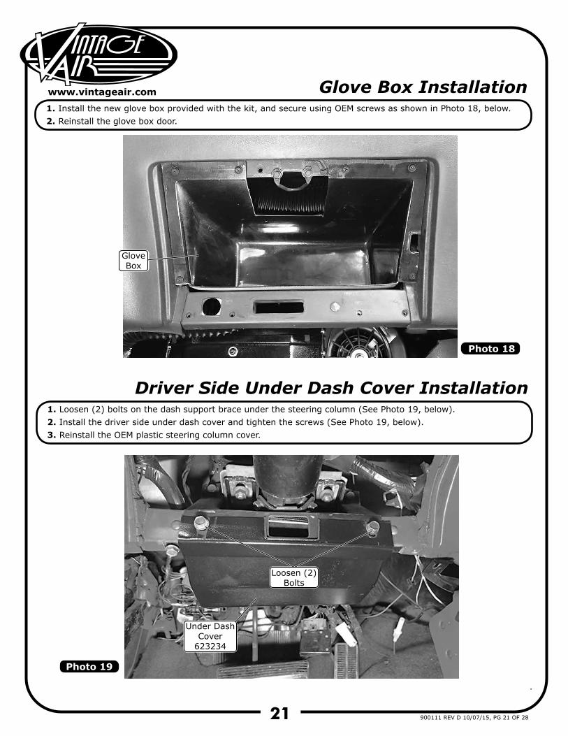
Glove Box Installation
Driver Side Under Dash Cover Installation
1.2.
1.2.3.
Install the new glove box provided with the kit, and secure using OEM screws as shown in Photo 18, below.Reinstall the glove box door.
Loosen (2) bolts on the dash support brace under the steering column (See Photo 19, below).Install the driver side under dash cover and tighten the screws (See Photo 19, below).Reinstall the OEM plastic steering column cover.
Loosen (2)Bolts
GloveBox
Under DashCover
623234
22
www.vintageair.com
900111 REV D 10/07/15, PG 22 OF 28
Figure 18
Control Panel & Duct Hose Routing
Control Panel Harness From ECU
232007-VUR
Driver SideLouver
2 ½” x 36”
Passenger SideLouver
2 ½” x 50”
Center Louver Driver Side2 ½” x 16”
Center Louver Passenger Side
2 ½” x 16”
Driver SideDefrost Duct
2” x 22”
Under DashDriver Side
2” x 18”
Under DashPassenger Side
2” x 18”
Passenger SideDefrost Duct
2” x 14” Plug FromControl Panel
Wiring Harness232007-VUR
Plug FromWiring
Harness232001-VUR
Back Side ofControl Panel Assembly
23
www.vintageair.com
900111 REV D 10/07/15, PG 23 OF 28
WHT/GRN
WHT/YELWHT/RED
RED
WHTBACKLIGHT NEG
FAN WIPER
MODE WIPER
TEMP WIPER
5V-SW
GND
BACKLIGHT POS
AC ANNUNCIATOR
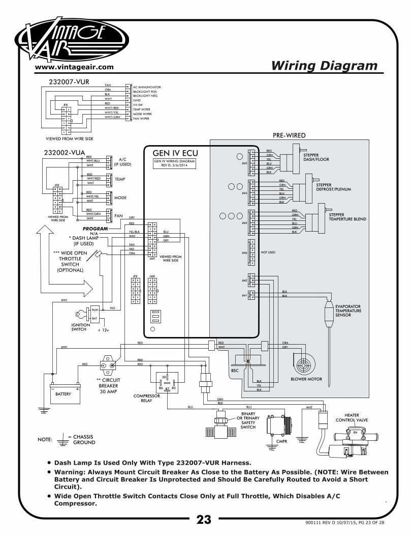
PRE-WIRED
GEN IV WIRING DIAGRAMREV D, 5/6/2014
GEN IV ECU
PROGRAM
Wiring Diagram
TEMP
MODE
FAN
A/C(IF USED)
232007-VUR
232002-VUA
** CIRCUITBREAKER30 AMP
*** WIDE OPENTHROTTLESWITCH
(OPTIONAL)
* DASH LAMP(IF USED)
Dash Lamp Is Used Only With Type 232007-VUR Harness.Warning: Always Mount Circuit Breaker As Close to the Battery As Possible. (NOTE: Wire BetweenBattery and Circuit Breaker Is Unprotected and Should Be Carefully Routed to Avoid a ShortCircuit).Wide Open Throttle Switch Contacts Close Only at Full Throttle, Which Disables A/C Compressor.
JF8
BLK
ORA
TAN
VIEWED FROM WIRE SIDE
••
•
HEATERCONTROL VALVE
24
www.vintageair.com
900111 REV D 10/07/15, PG 24 OF 28
RED
CIRCUIT BREAKER30 AMP
+
+
-
BLACK
REDWHITE
RED
CHASSIS GROUND
A/CCOMPRESSOR
RELAY
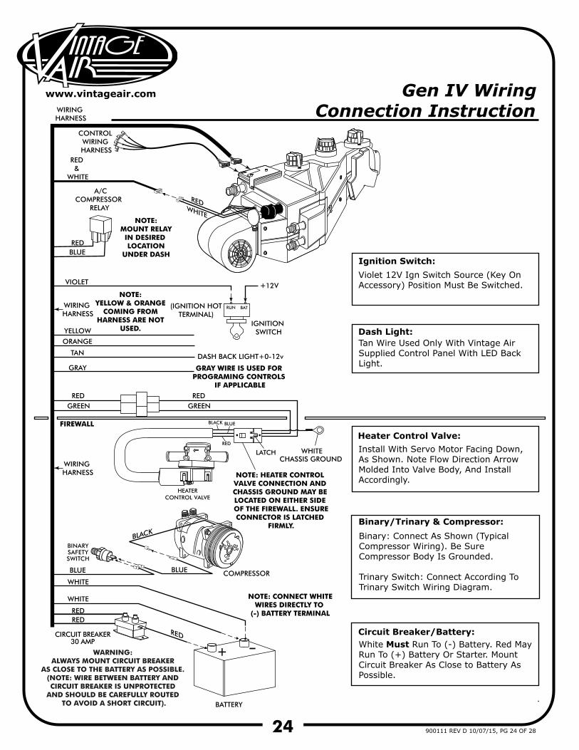
Ignition Switch:
Dash Light:
NOTE: MOUNT RELAYIN DESIRED LOCATION
UNDER DASH
GREEN
FIREWALL
BLUE
BLUE
RED &
WHITE
VIOLET
(IGNITION HOTTERMINAL)
IGNITION SWITCH
DASH BACK LIGHT+0-12vTAN
GRAY
BLUE
WHITE
WHITE
REDRED
WHITE
COMPRESSOR
BATTERY
NOTE: CONNECT WHITEWIRES DIRECTLY TO
(-) BATTERY TERMINAL
BATRUN
12V
RED GREEN
RED
RED
BLUE
LATCH
BLACK
BINARYSAFETYSWITCH
YELLOW
ORANGE
WIRING HARNESS
Violet 12V Ign Switch Source (Key On Accessory) Position Must Be Switched.
Tan Wire Used Only With Vintage Air Supplied Control Panel With LED Back Light.
Binary: Connect As Shown (Typical Compressor Wiring). Be Sure Compressor Body Is Grounded.
Trinary Switch: Connect According To Trinary Switch Wiring Diagram.
Install With Servo Motor Facing Down, As Shown. Note Flow Direction Arrow Molded Into Valve Body, And Install Accordingly.
White Must Run To (-) Battery. Red May Run To (+) Battery Or Starter. Mount Circuit Breaker As Close to Battery As Possible.
Heater Control Valve:
Binary/Trinary & Compressor:
Circuit Breaker/Battery:
CONTROL WIRING HARNESS
NOTE: YELLOW & ORANGE
COMING FROM HARNESS ARE NOT
USED.
WIRING HARNESS
GRAY WIRE IS USED FOR PROGRAMING CONTROLS
IF APPLICABLE
WIRING HARNESS
Gen IV Wiring Connection Instruction
HEATERCONTROL VALVE
WARNING: ALWAYS MOUNT CIRCUIT BREAKER
AS CLOSE TO THE BATTERY AS POSSIBLE. (NOTE: WIRE BETWEEN BATTERY AND CIRCUIT BREAKER IS UNPROTECTED
AND SHOULD BE CAREFULLY ROUTED TO AVOID A SHORT CIRCUIT).
NOTE: HEATER CONTROL VALVE CONNECTION AND CHASSIS GROUND MAY BE LOCATED ON EITHER SIDE OF THE FIREWALL. ENSURECONNECTOR IS LATCHED
FIRMLY.
25
www.vintageair.com
900111 REV D 10/07/15, PG 25 OF 28
Adjust to desiredspeed.
Blower SpeedAdjust to desired
speed.
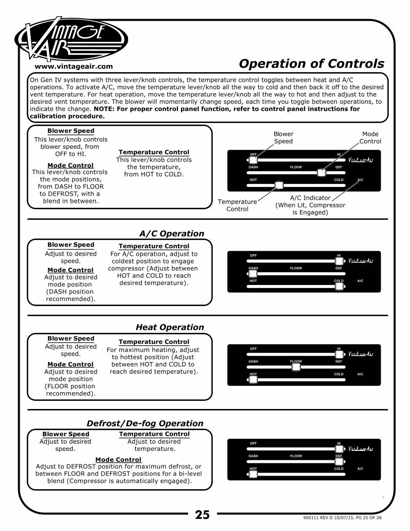
Adjust to desiredmode position (DASH position recommended).
Adjust to desiredspeed.
Adjust to DEFROST position for maximum defrost, or between FLOOR and DEFROST positions for a bi-level
blend (Compressor is automatically engaged).
Adjust to desired temperature.
For A/C operation, adjust tocoldest position to engage
compressor (Adjust between HOT and COLD to reachdesired temperature).
A/C Operation
Heat Operation
Defrost/De-fog Operation
Blower Speed
Blower Speed
This lever/knob controlsblower speed, from
OFF to HI.
This lever/knob controls the mode positions,from DASH to FLOORto DEFROST, with a blend in between.
This lever/knob controlsthe temperature,
from HOT to COLD.
Blower Speed
Mode Control
Temperature Control
Blower Speed
TemperatureControl
ModeControl
A/C Indicator(When Lit, Compressor
is Engaged)
Temperature Control
Temperature Control
Temperature Control
Mode Control
Mode Control
Mode Control
For maximum heating, adjust to hottest position (Adjust between HOT and COLD to reach desired temperature).Adjust to desired
mode position(FLOOR position recommended).
Operation of ControlsOn Gen IV systems with three lever/knob controls, the temperature control toggles between heat and A/C operations. To activate A/C, move the temperature lever/knob all the way to cold and then back it off to the desired vent temperature. For heat operation, move the temperature lever/knob all the way to hot and then adjust to the desired vent temperature. The blower will momentarily change speed, each time you toggle between operations, to indicate the change. NOTE: For proper control panel function, refer to control panel instructions for calibration procedure.
ww
w.v
inta
gea
ir.c
om
26 900111 REV D 10/07/15, PG 26 OF 28
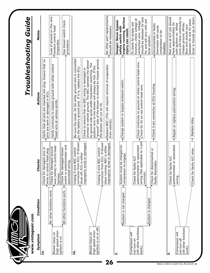
Sym
pto
m
C
on
dit
ion
C
heck
s
Act
ion
s
N
ote
s
Blo
wer
sta
ys o
n
hig
h s
pee
d w
hen
ig
nitio
n is
on.
1a.
No o
ther
funct
ions
work
.
Chec
k fo
r dam
aged
pin
s or
wires
in c
ontr
ol hea
d p
lug.
Ver
ify
that
all
pin
s ar
e in
sert
ed into
plu
g.
Ensu
re t
hat
no
pin
s ar
e ben
t or
dam
aged
in E
CU
.
Chec
k fo
r dam
aged
gro
und
wire
(white)
in c
ontr
ol hea
d
har
nes
s.
Ver
ify
continuity
to c
has
sis
gro
und w
ith w
hite
contr
ol
hea
d w
ire
at v
ario
us
poin
ts.
Loss
of gro
und o
n t
his
wire
render
s co
ntr
ol hea
d
inoper
able
.
All
oth
er f
unct
ions
work
.Chec
k fo
r dam
aged
blo
wer
sw
itch
or
pote
ntiom
eter
and
asso
ciat
ed w
irin
g.
Blo
wer
sta
ys o
n
hig
h s
pee
d w
hen
ig
nitio
n is
on o
r off.
Unplu
g 3
-wire
BSC c
ontr
ol
connec
tor
from
ECU
. If
blo
wer
sh
uts
off,
ECU
is
eith
er
impro
per
ly w
ired
or
dam
aged
.
Be
sure
the
smal
l, 2
0 G
A w
hite
gro
und w
ire
is c
onnec
ted
to t
he
bat
tery
gro
und p
ost
. If
it
is,
repla
ce t
he
ECU
.
Unplu
g 3
-wire
BSC c
ontr
ol
connec
tor
from
ECU
. If
blo
wer
st
ays
runnin
g,
BSC is
eith
er
impro
per
ly w
ired
or
dam
aged
.
Chec
k to
ensu
re t
hat
no B
SC w
irin
g is
dam
aged
or
short
ed t
o v
ehic
le g
round.
The
BSC o
per
ates
the
blo
wer
by
gro
und s
ide
puls
e w
idth
modula
tion s
witch
ing.
The
posi
tive
wire
to t
he
blo
wer
will
alw
ays
be
hot.
If th
e “g
round”
side
of
the
blo
wer
is
short
ed t
o c
has
sis
gro
und,
the
blo
wer
will
run o
n H
I.
Rep
lace
BSC (
This
will
req
uire
rem
oval
of
evap
ora
tor
from
veh
icle
).N
o o
ther
par
t re
pla
cem
ents
sh
ould
be
nec
essa
ry.
Com
pre
ssor
will
not
turn
on
(All
oth
er funct
ions
work
).
2.
Sys
tem
is
not
char
ged
.Sys
tem
must
be
char
ged
for
com
pre
ssor
to e
ngag
e.Char
ge
syst
em o
r byp
ass
pre
ssure
sw
itch
.
Dan
ger:
Never
byp
ass
sa
fety
sw
itch
wit
h
en
gin
e r
un
nin
g.
Seri
ou
s in
jury
can
resu
lt.
Sys
tem
is
char
ged
.
1b
.
Tro
ub
lesh
oo
tin
g G
uid
e
Chec
k fo
r fa
ulty
A/C
pote
ntiom
eter
or
asso
ciat
ed
wirin
g (
Not
applic
able
to 3
-pot
contr
ols
).
Chec
k fo
r dis
connec
ted o
r fa
ulty
ther
mis
tor.
Chec
k co
ntinuity
to g
round o
n w
hite
contr
ol hea
d w
ire.
Chec
k fo
r 5V o
n r
ed c
ontr
ol hea
d w
ire.
Chec
k 2-p
in c
onnec
tor
at E
CU
housi
ng.
To c
hec
k fo
r pro
per
pot
funct
ion,
chec
k vo
ltag
e at
w
hite/
blu
e w
ire.
Voltag
e sh
ould
be
bet
wee
n 0
V a
nd
5V,
and w
ill v
ary
with p
ot
leve
r posi
tion.
Dis
connec
ted o
r fa
ulty
ther
mis
tor
will
cau
se
com
pre
ssor
to b
e dis
able
d.
Red
wire
at A
/C p
ot
should
hav
e ap
pro
xim
atel
y 5V
with ignitio
n o
n.
White
wire
will
hav
e co
ntinuity
to
chas
sis
gro
und.
White/
Blu
e w
ire
should
var
y bet
wee
n 0
V a
nd 5
V w
hen
le
ver
is m
oved
up o
r dow
n.
3. Com
pre
ssor
will
not
turn
off
(A
ll oth
er funct
ions
work
).
Chec
k fo
r fa
ulty
A/C
pote
ntiom
eter
or
asso
ciat
ed
wirin
g.
Chec
k fo
r fa
ulty
A/C
rel
ay.
Rep
air
or
repla
ce p
ot/
contr
ol w
irin
g.
Rep
lace
rel
ay.
See
blo
wer
sw
itch
chec
k pro
cedure
.
ww
w.v
inta
gea
ir.c
om
27 900111 REV D 10/07/15, PG 27 OF 28
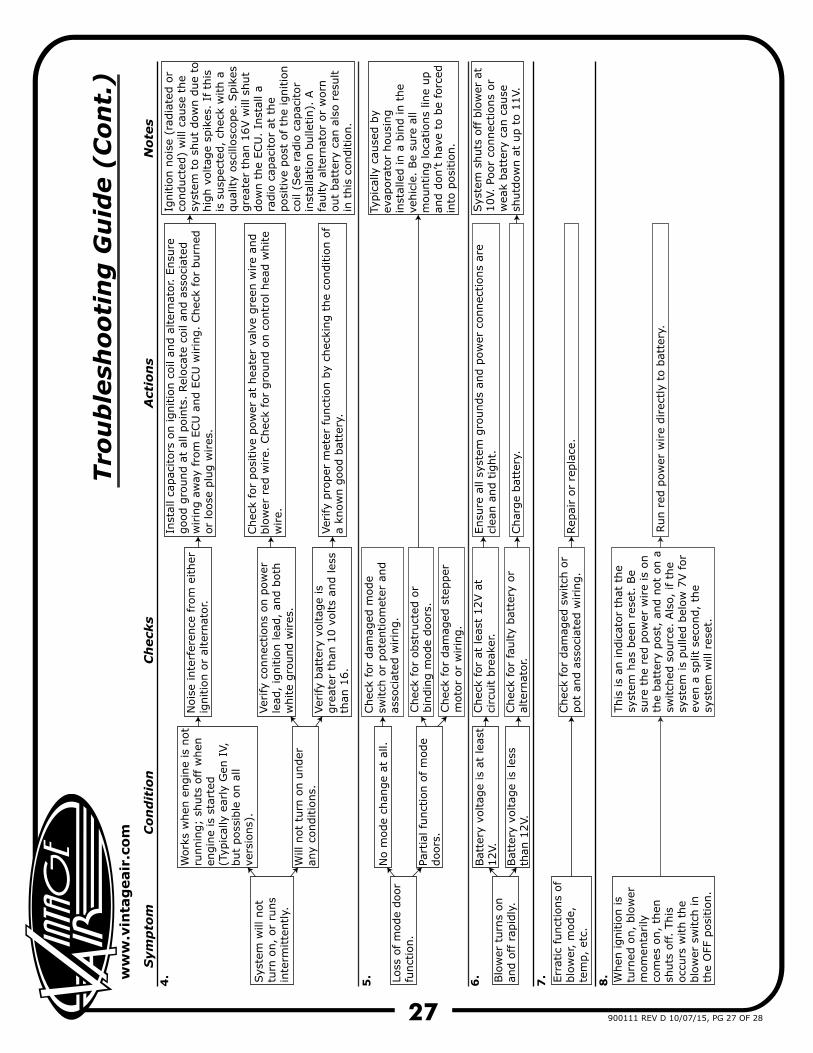
Sym
pto
m
C
on
dit
ion
Ch
eck
s
Act
ion
s
N
ote
s
Sys
tem
will
not
turn
on,
or
runs
inte
rmitte
ntly.
4.
Work
s w
hen
engin
e is
not
runnin
g;
shuts
off w
hen
en
gin
e is
sta
rted
(T
ypic
ally
ear
ly G
en I
V,
but
poss
ible
on a
ll ve
rsio
ns)
.
Nois
e in
terf
eren
ce f
rom
either
ig
nitio
n o
r al
tern
ator.
Inst
all ca
pac
itors
on ignitio
n c
oil
and a
lter
nat
or. E
nsu
re
good g
round a
t al
l poin
ts.
Rel
oca
te c
oil
and a
ssoci
ated
w
irin
g a
way
fro
m E
CU
and E
CU
wirin
g.
Chec
k fo
r burn
edor
loose
plu
g w
ires
.
Ver
ify
connec
tions
on p
ow
er
lead
, ig
nitio
n lea
d,
and b
oth
white
gro
und w
ires
.
Ver
ify
pro
per
met
er f
unct
ion b
y ch
ecki
ng t
he
conditio
n o
f a
know
n g
ood b
atte
ry.
Ignitio
n n
ois
e (r
adia
ted o
rco
nduct
ed)
will
cau
se t
he
syst
em t
o s
hut
dow
n d
ue
tohig
h v
oltag
e sp
ikes
. If
this
is s
usp
ecte
d,
chec
k w
ith a
qual
ity
osc
illosc
ope.
Spik
esgre
ater
than
16V w
ill s
hut
dow
n t
he
ECU
. In
stal
l a
radio
cap
acitor
at t
he
posi
tive
post
of th
e ig
nitio
nco
il (S
ee r
adio
cap
acitor
inst
alla
tion b
ulle
tin).
A
faulty
alte
rnat
or
or
worn
out
bat
tery
can
als
o r
esult
in t
his
conditio
n.
Will
not
turn
on u
nder
an
y co
nditio
ns.
Ver
ify
bat
tery
voltag
e is
gre
ater
than
10 v
olts
and les
sth
an 1
6.
Loss
of m
ode
door
funct
ion.
No m
ode
chan
ge
at a
ll.Chec
k fo
r dam
aged
mode
switch
or
pote
ntiom
eter
and
asso
ciat
ed w
irin
g.
Part
ial fu
nct
ion o
f m
ode
doors
.
Typic
ally
cau
sed b
y ev
apora
tor
housi
ng
inst
alle
d in a
bin
d in t
he
vehic
le.
Be
sure
all
mounting loca
tions
line
up
and d
on’t h
ave
to b
e fo
rced
in
to p
osi
tion.
Blo
wer
turn
s on
and o
ff r
apid
ly.
6.
Bat
tery
voltag
e is
at
leas
t 12V.
Chec
k fo
r at
lea
st 1
2V a
t ci
rcuit b
reak
er.
Ensu
re a
ll sy
stem
gro
unds
and p
ow
er c
onnec
tions
are
clea
n a
nd t
ight.
Bat
tery
voltag
e is
les
s th
an 1
2V.
5.
Tro
ub
lesh
oo
tin
g G
uid
e (
Co
nt.
)
Chec
k fo
r fa
ulty
bat
tery
or
alte
rnat
or.
Char
ge
bat
tery
.
Sys
tem
shuts
off b
low
er a
t 10V.
Poor
connec
tions
or
wea
k bat
tery
can
cau
se
shutd
ow
n a
t up t
o 1
1V.
7. When
ignitio
n is
turn
ed o
n,
blo
wer
m
om
enta
rily
co
mes
on,
then
sh
uts
off.
This
occ
urs
with t
he
blo
wer
sw
itch
in
the
OFF
posi
tion.
This
is
an indic
ator
that
the
syst
em h
as b
een r
eset
. Be
sure
the
red p
ow
er w
ire
is o
nth
e bat
tery
post
, an
d n
ot
on a
sw
itch
ed s
ourc
e. A
lso,
if
the
syst
em is
pulle
d b
elow
7V f
or
even
a s
plit
sec
ond,
the
syst
em w
ill r
eset
.
Run r
ed p
ow
er w
ire
direc
tly
to b
atte
ry.
Chec
k fo
r posi
tive
pow
er a
t hea
ter
valv
e gre
en w
ire
and
blo
wer
red
wire.
Chec
k fo
r gro
und o
n c
ontr
ol hea
d w
hite
wire.
Chec
k fo
r obst
ruct
ed o
r bin
din
g m
ode
doors
.
Chec
k fo
r dam
aged
ste
pper
m
oto
r or
wirin
g.
Err
atic
funct
ions
of
blo
wer
, m
ode,
te
mp,
etc.
Chec
k fo
r dam
aged
sw
itch
or
pot
and a
ssoci
ated
wirin
g.
Rep
air
or
repla
ce.
8.
28
www.vintageair.com
900111 REV D 10/07/15, PG 28 OF 28
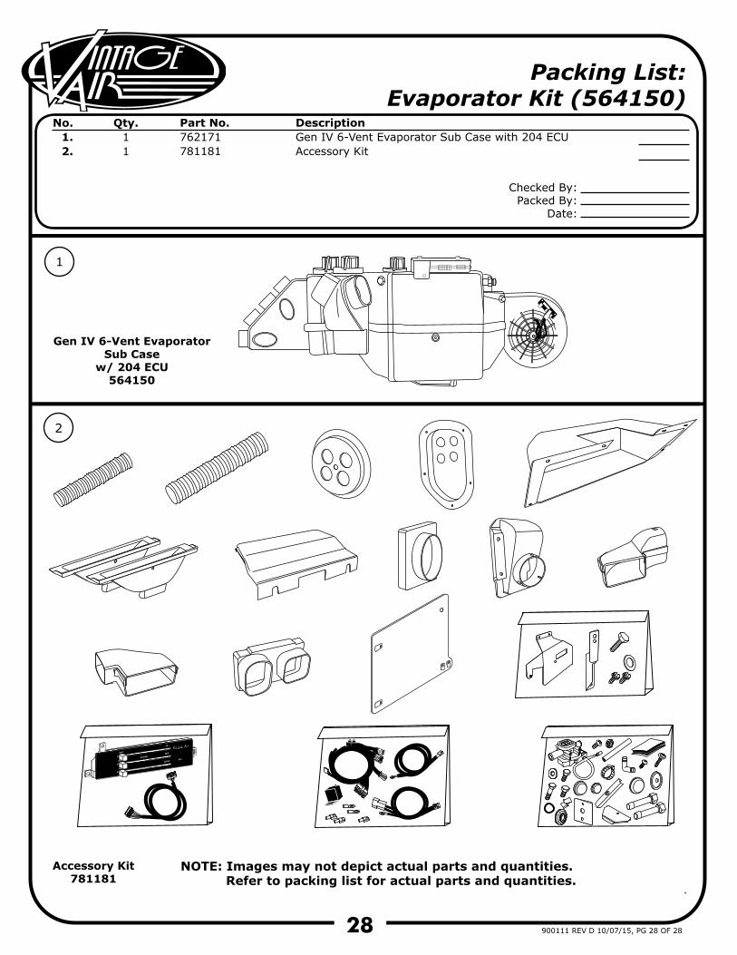
Packing List: Evaporator Kit (564150)
No. 1.2.
Qty.11
Part No.762171781181
DescriptionGen IV 6-Vent Evaporator Sub Case with 204 ECUAccessory Kit
NOTE: Images may not depict actual parts and quantities. Refer to packing list for actual parts and quantities.
1
2
Gen IV 6-Vent Evaporator Sub Case
w/ 204 ECU564150
Accessory Kit781181
Checked By:Packed By:
Date: