Embed Size (px)
Citation preview
1970-74 Challenger/CudaGen IV
with Factory Air574074-EDZ
907074-EDZ REV E 8/08/14, INST. GEN IV 70-74 CHALNGR/CUDA w/ AC EVAP PG 1 OF 24
an ISO 9001:2008 Registered Company
18865 Goll St. San Antonio, TX 78266 ph: 210-654-7171 fax: 210-654-3113
2907074-EDZ REV E 8/08/14, INST. GEN IV 70-74 CHALNGR/CUDA w/ AC EVAP PG 2 OF 24
1. Cover 2. Table of Contents 3. Packing List/Parts Disclaimer 4. Information Page 5. Wiring Notice 6. Engine Compartment Figure 1 7. Condenser, Compressor Bracket, & Passenger Compartment Figures 2 & 3 8. Passenger Compartment (Cont.) Figures 4 & 5 9. Fresh Air Cap & A/C Duct Hose Adapter Installation Figures 6, 7, & 810. Evaporator Installation Figure 911. Evaporator Installation (Cont.) Figures 10, 10a, & 10b12. Firewall Cover Installation Figure 1113. Drain Hose Installation Figures 12 & 12a14. A/C & Heater Hose Installation15. A/C Hose Routing Figures 13 & 13a16. Heater Control Valve Installation Figure 1417. Control Panel Wiring & Duct Hose Routing Figure 1518. Evaporator Hardline & Bracket Installation Figure 1619. Wiring Diagram20. Gen IV Wiring Connection Instructions21. Operation Of Controls22. Troubleshooting Information23. Troubleshooting Information (Cont.)24. Evaporator Kit Packing List
Table of Contents
3907074-EDZ REV E 8/08/14, INST. GEN IV 70-74 CHALNGR/CUDA w/ AC EVAP PG 3 OF 24
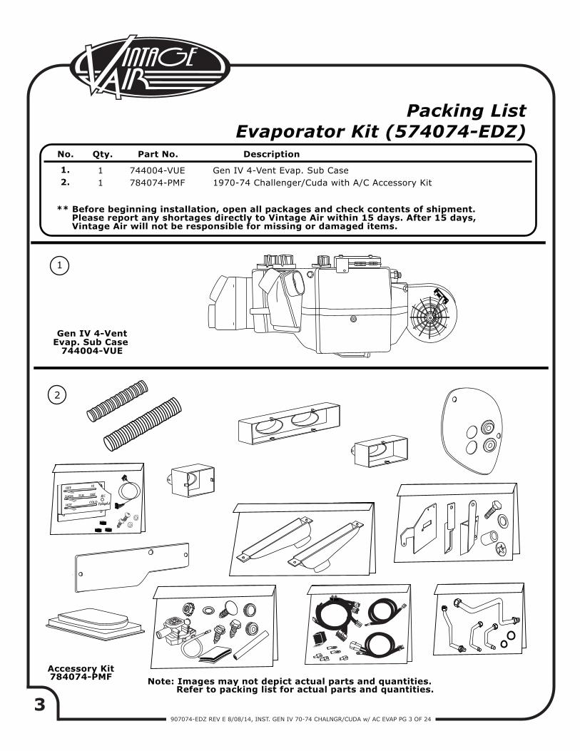
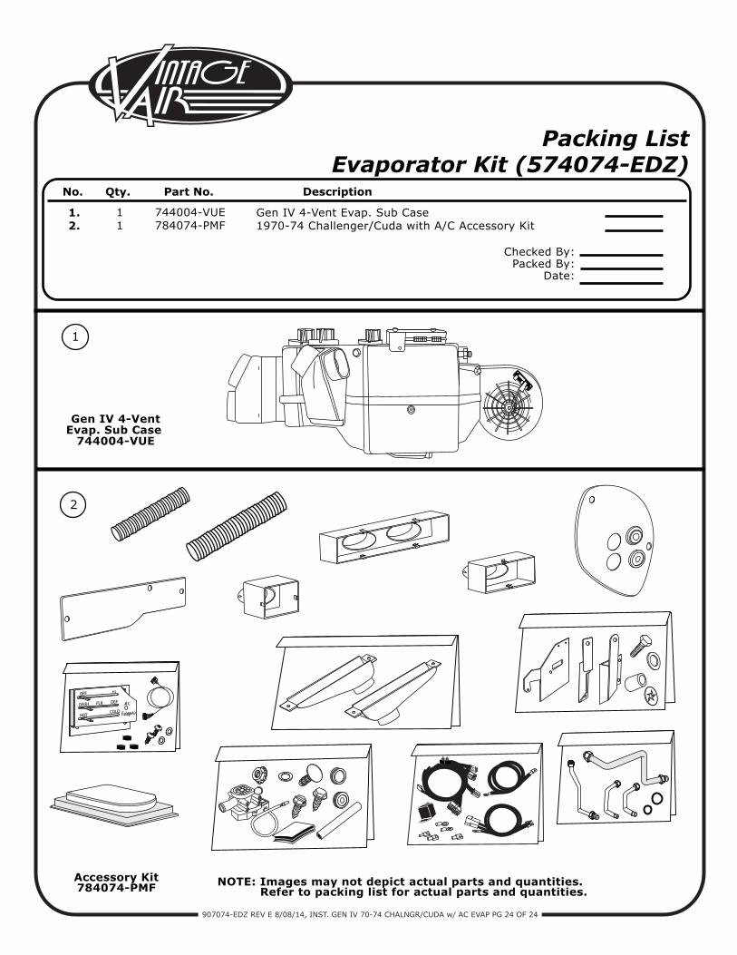
** Before beginning installation, open all packages and check contents of shipment. Please report any shortages directly to Vintage Air within 15 days. After 15 days, Vintage Air will not be responsible for missing or damaged items.
Packing ListEvaporator Kit (574074-EDZ)
No. Qty. Part No. Description
1.2.
11
744004-VUE784074-PMF
Gen IV 4-Vent Evap. Sub Case 1970-74 Challenger/Cuda with A/C Accessory Kit
1
Accessory Kit784074-PMF
2
Note: Images may not depict actual parts and quantities. Refer to packing list for actual parts and quantities.
OFF
DASH
HOT
FLR
HI
DEF
COLD
AC
Gen IV 4-VentEvap. Sub Case
744004-VUE
4907074-EDZ REV E 8/08/14, INST. GEN IV 70-74 CHALNGR/CUDA w/ AC EVAP PG 4 OF 24
Use of Any Other Refrigerants Will Void All Warranties of the Air Conditioning System and Components. Use of the Proper Type and
Amount of Refrigerant Is Critical to Proper System Operation. VintageAir Recommends Our Systems Be Charged By Weight With a Quality
Charging Station or Scale.
Service Info:
Safety Switches:
Important Notice—Please Read
Attention: The following system components are capped: Compressor, evaporator, condenser & drier. Caps may be under pressure with dry nitrogen. Be careful removing caps. Do not remove caps prior to installation. Removing caps prior to installation will cause components to collect moisture and lead to premature failure and reduced performance.
Evacuate the system for 35-45 minutes with system components (Drier, compressor, evaporator and condenser) at a temperature of at least 85° F. On a cool day, the components can be heated with a heat gun OR by running the engine with the heater on before evacuating. Leak check and charge to specifications.
For Maximum System Performance, Vintage Air Recommends the Following:
Heater hose may be purchased from Vintage Air (Part# 31800-VUD) or your local parts retailer. Routing and required length will vary based on installer preference.
Vintage Air Systems Are Designed to Operate With R134a Refrigerant Only! Use of Any Other Refrigerants Is a Fire Hazard and Could Damage Either Your Air Conditioning System or Your Vehicle.
Refrigerant Capacity for Vintage Air Systems:(For other systems, consult manufacturer’s guidelines)
R134a SystemCharge with 1.8 lbs. (1 lb., 12 oz.) of refrigerant.
Lubricant Capacities:New Vintage Air-supplied Sanden Compressor: No additional oil needed (Compressor is shipped with proper oil charge).All Other Compressors: Consult manufacturer (Some compressors are shipped dry and will need oil added).
Your Vintage Air system is equipped with a binary pressure safety switch. A binary switch disengages the compressor clutch in cases of extreme low pressure conditions (Refrigerant Loss) or excessively high head pressure (406 PSI) to prevent compressor damage or hose rupture. A trinary switch combines Hi/Lo pressure protection with an electric fan operation signal at 254 PSI, and should be substituted for use with electric fans. Compressor safety switches are extremely important since an A/C system relies on refrigerant to circulate lubricant.
Heater Hose (Not Included With This Kit):
To ensure a watertight seal between the passenger compartment and the vehicle exterior, for all bolts passing through the cowl and/or firewall, Vintage Air recommends coating the threads with silicone prior to installation.
Bolts Passing Through Cowl and/or Firewall:
5907074-EDZ REV E 8/08/14, INST. GEN IV 70-74 CHALNGR/CUDA w/ AC EVAP PG 5 OF 24
Important Wiring Notice—Please Read
Some Vehicles May Have Had Some or All of Their Radio Interference Capacitors Removed. There Should Be a Capacitor Found At Each of the Following Locations:
1. On the positive terminal of the ignition coil.2. If there is a generator, on the armature terminal of the generator.3. If there is a generator, on the battery terminal of the voltage regulator.
Most alternators have a capacitor installed internally to eliminate what is called “whining” as the engine is revved. If whining is heard in the radio, or just to be extra cautious, a radio interference capacitor can be added to the battery terminal of the alternator.
It is also important that the battery lead is in good shape and that the ground leads are not compromised. There should be a heavy ground from the battery to the engine block, and additional grounds to the body and chassis.
If these precautions are not observed, it is possible for voltage spikes to be present on the battery leads. These spikes come from ignition systems, charging systems, and from switching some of the vehicle’s other systems on and off. Modern computer-operated equipment can be sensitive to voltage spikes on the power leads, which can cause unexpected resets, strange behavior, and/or permanent damage.
Vintage Air strives to harden our products against these types of electrical noise, but there is a point where a vehicle’s electrical system can be degraded so much that nothing can help.
Radio interference capacitors should be available at most auto and truck parts suppliers. They typically are cylindrical in shape, a little over an inch long, a little over a half inch in diameter, and they have a single lead coming from one end of the cylinder with a terminal on the end of the wire, as well as a mounting clip which is screwed into a good ground on the vehicle. The specific value of the capacitance is not too significant in comparison to ignition capacitors that are matched with the coil to reduce pitting of the points.
Care must be taken, when installing the compressor lead, not to short it to ground. The compressor lead must not be connected to a condenser fan or to any other auxiliary device. Shorting to ground or connecting to a condenser fan or any other auxiliary device may damage wiring, the compressor relay, and/or cause a malfunction.
When installing ground leads on Gen IV systems, the blower control ground and ECU ground must be connected directly to the negative battery post.
For proper system operation, the heater control valve must be connected to the ECU.
•
•
•
6907074-EDZ REV E 8/08/14, INST. GEN IV 70-74 CHALNGR/CUDA w/ AC EVAP PG 6 OF 24
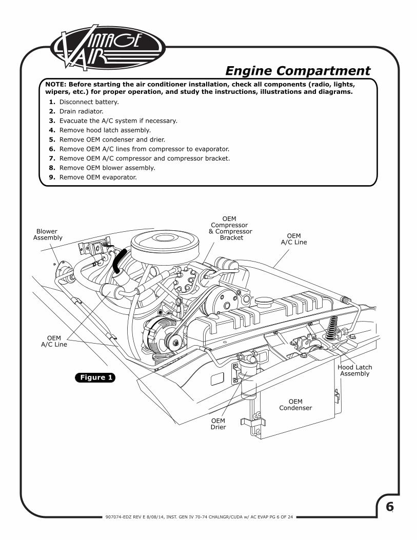
OEM A/C Line
OEM A/C Line
Blower Assembly
OEM Compressor
& Compressor Bracket
Figure 1
OEM Condenser
OEM Drier
Hood LatchAssembly
Engine Compartment
Disconnect battery.Drain radiator.Evacuate the A/C system if necessary.Remove hood latch assembly.Remove OEM condenser and drier.Remove OEM A/C lines from compressor to evaporator.Remove OEM A/C compressor and compressor bracket.Remove OEM blower assembly.Remove OEM evaporator.
1.2.3.4.5.6.7.8.9.
NOTE: Before starting the air conditioner installation, check all components (radio, lights, wipers, etc.) for proper operation, and study the instructions, illustrations and diagrams.
7907074-EDZ REV E 8/08/14, INST. GEN IV 70-74 CHALNGR/CUDA w/ AC EVAP PG 7 OF 24
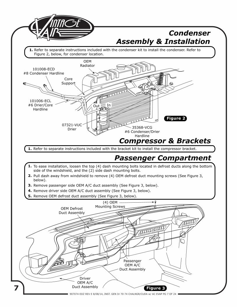
Figure 2
Figure 3
Condenser Assembly & Installation
Compressor & Brackets
Passenger Compartment
Refer to separate instructions included with the condenser kit to install the condenser. Refer to Figure 2, below, for condenser location.
Refer to separate instructions included with the bracket kit to install the compressor bracket.
To ease installation, loosen the top (4) dash mounting bolts located in defrost ducts along the bottom side of the windshield, and the (2) side dash mounting bolts.Pull dash away from windshield to remove (4) OEM defrost duct mounting screws (See Figure 3, below).Remove passenger side OEM A/C duct assembly (See Figure 3, below).Remove driver side OEM A/C duct assembly (See Figure 3, below).Remove OEM defrost duct assembly (See Figure 3, below).
1.
1.
1.
2.
3.4.5.
OEMRadiator
Out In
CoreSupport
07321-VUCDrier
(4) OEMMounting ScrewsOEM Defrost
Duct Assembly
DriverOEM A/C
Duct Assembly
PassengerOEM A/C
Duct Assembly
101008-ECD#8 Condenser Hardline
101006-ECL#6 Drier/Core
Hardline
35368-VCG#6 Condenser/Drier
Hardline
8907074-EDZ REV E 8/08/14, INST. GEN IV 70-74 CHALNGR/CUDA w/ AC EVAP PG 8 OF 24
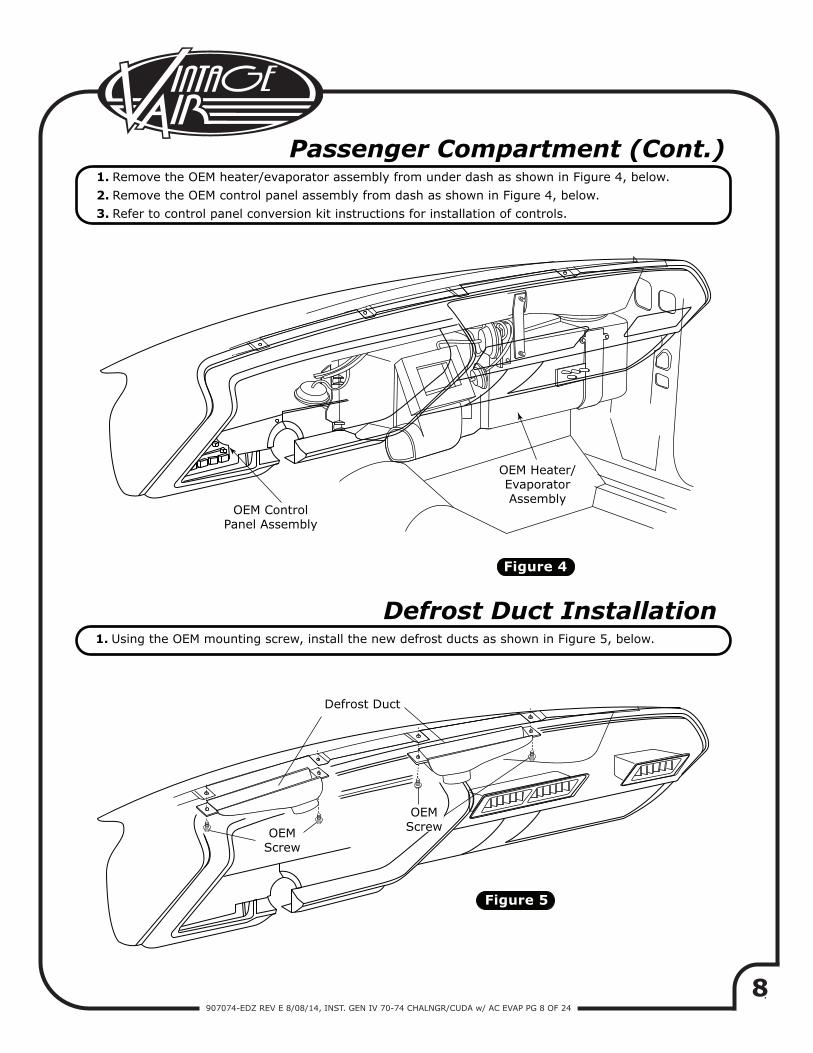
Figure 5
Figure 4
Passenger Compartment (Cont.)Remove the OEM heater/evaporator assembly from under dash as shown in Figure 4, below.
Remove the OEM control panel assembly from dash as shown in Figure 4, below.
Refer to control panel conversion kit instructions for installation of controls.
Using the OEM mounting screw, install the new defrost ducts as shown in Figure 5, below.
1.
2.
3.
1.
Defrost Duct Installation
OEM ControlPanel Assembly
OEM Heater/EvaporatorAssembly
Defrost Duct
OEMScrew
OEMScrew
9907074-EDZ REV E 8/08/14, INST. GEN IV 70-74 CHALNGR/CUDA w/ AC EVAP PG 9 OF 24
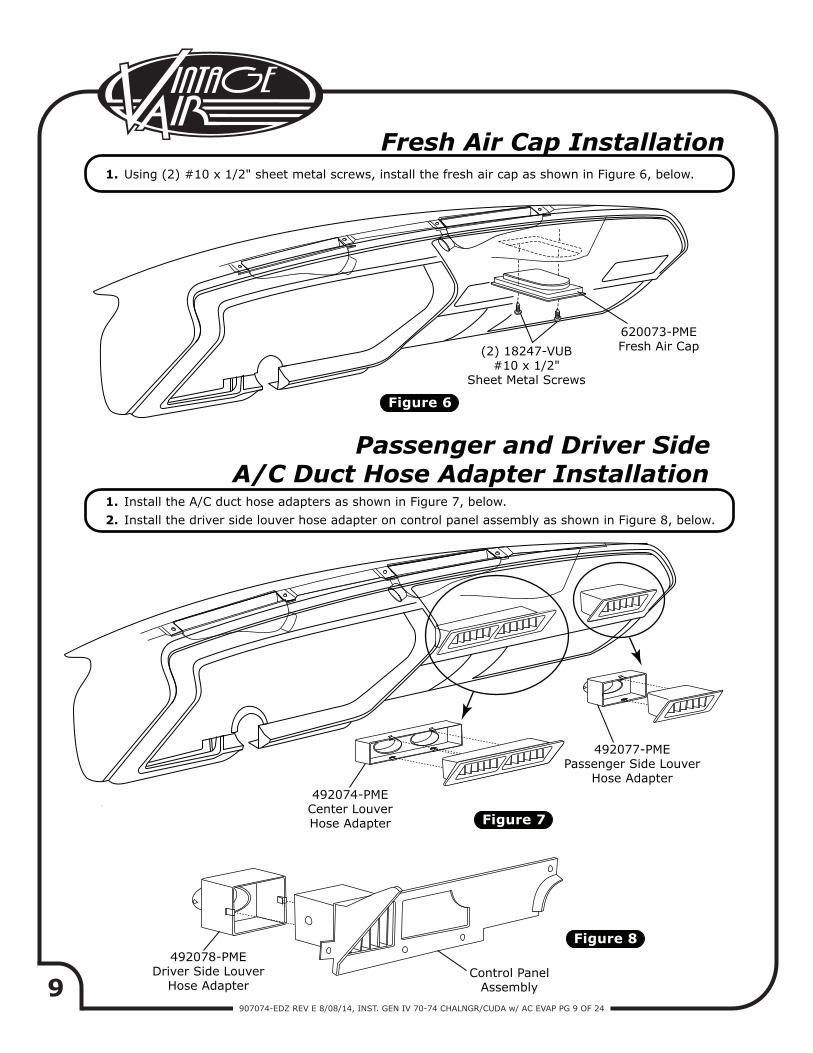
Figure 6
Figure 8
Figure 7
Fresh Air Cap InstallationUsing (2) #10 x 1/2" sheet metal screws, install the fresh air cap as shown in Figure 6, below.1.
Passenger and Driver SideA/C Duct Hose Adapter Installation
Install the A/C duct hose adapters as shown in Figure 7, below.Install the driver side louver hose adapter on control panel assembly as shown in Figure 8, below.
1.2.
(2) 18247-VUB#10 x 1/2"
Sheet Metal Screws
620073-PMEFresh Air Cap
492077-PMEPassenger Side Louver
Hose Adapter492074-PME
Center LouverHose Adapter
492078-PMEDriver Side Louver
Hose AdapterControl Panel
Assembly
10907074-EDZ REV E 8/08/14, INST. GEN IV 70-74 CHALNGR/CUDA w/ AC EVAP PG 10 OF 24
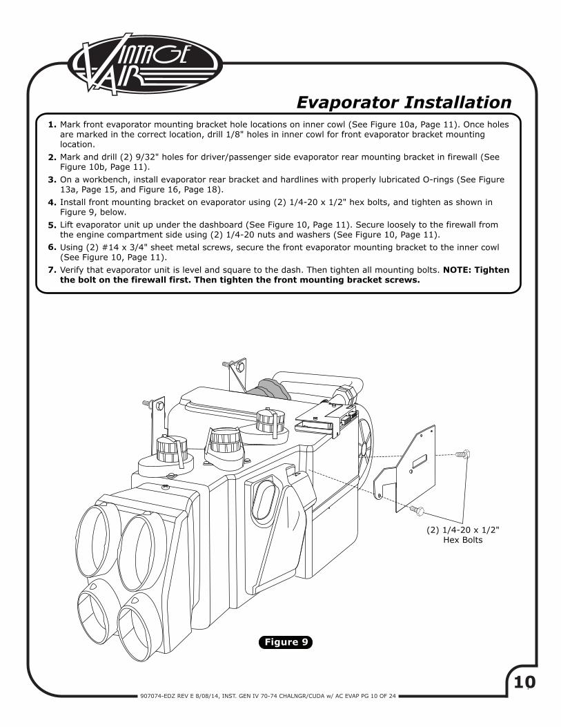
Figure 9
Evaporator InstallationMark front evaporator mounting bracket hole locations on inner cowl (See Figure 10a, Page 11). Once holes are marked in the correct location, drill 1/8" holes in inner cowl for front evaporator bracket mounting location.Mark and drill (2) 9/32" holes for driver/passenger side evaporator rear mounting bracket in firewall (SeeFigure 10b, Page 11).On a workbench, install evaporator rear bracket and hardlines with properly lubricated O-rings (See Figure 13a, Page 15, and Figure 16, Page 18).Install front mounting bracket on evaporator using (2) 1/4-20 x 1/2" hex bolts, and tighten as shown in Figure 9, below.Lift evaporator unit up under the dashboard (See Figure 10, Page 11). Secure loosely to the firewall fromthe engine compartment side using (2) 1/4-20 nuts and washers (See Figure 10, Page 11).Using (2) #14 x 3/4" sheet metal screws, secure the front evaporator mounting bracket to the inner cowl(See Figure 10, Page 11).Verify that evaporator unit is level and square to the dash. Then tighten all mounting bolts. NOTE: Tighten the bolt on the firewall first. Then tighten the front mounting bracket screws.
1.
2.
3.
4.
5.
6.
7.
(2) 1/4-20 x 1/2"Hex Bolts
11907074-EDZ REV E 8/08/14, INST. GEN IV 70-74 CHALNGR/CUDA w/ AC EVAP PG 11 OF 24
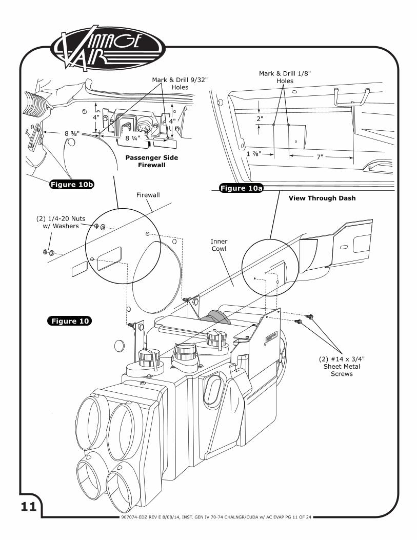
Figure 10
Figure 10aFigure 10b
Mark & Drill 9/32"Holes
4" 4" 2"
7"1 ⅞"
8 ⅜"8 ¼"
Passenger SideFirewall
(2) 1/4-20 Nutsw/ Washers
Firewall
InnerCowl
View Through Dash
(2) #14 x 3/4"Sheet Metal
Screws
Mark & Drill 1/8"Holes
12907074-EDZ REV E 8/08/14, INST. GEN IV 70-74 CHALNGR/CUDA w/ AC EVAP PG 12 OF 24
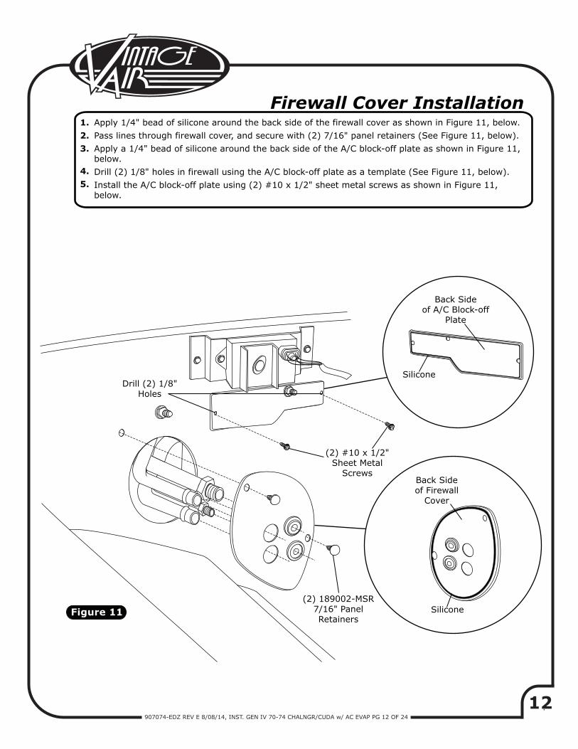
Figure 11
Firewall Cover InstallationApply 1/4" bead of silicone around the back side of the firewall cover as shown in Figure 11, below.Pass lines through firewall cover, and secure with (2) 7/16" panel retainers (See Figure 11, below).Apply a 1/4" bead of silicone around the back side of the A/C block-off plate as shown in Figure 11, below.Drill (2) 1/8" holes in firewall using the A/C block-off plate as a template (See Figure 11, below).Install the A/C block-off plate using (2) #10 x 1/2" sheet metal screws as shown in Figure 11,below.
1.2.3.
4.5.
Back Sideof A/C Block-off
Plate
Back Sideof Firewall
Cover
(2) #10 x 1/2"Sheet Metal
Screws
Drill (2) 1/8"Holes
(2) 189002-MSR7/16" PanelRetainers
Silicone
Silicone
13907074-EDZ REV E 8/08/14, INST. GEN IV 70-74 CHALNGR/CUDA w/ AC EVAP PG 13 OF 24
Figure 12a
Figure 12
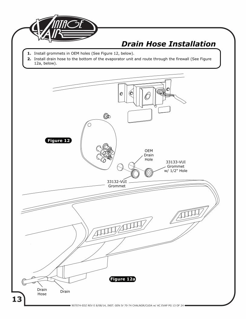
Drain Hose InstallationInstall grommets in OEM holes (See Figure 12, below).Install drain hose to the bottom of the evaporator unit and route through the firewall (See Figure12a, below).
1.2.
OEMDrainHole
33133-VUIGrommet
w/ 1/2" Hole
33132-VUIGrommet
DrainHose
Drain
14907074-EDZ REV E 8/08/14, INST. GEN IV 70-74 CHALNGR/CUDA w/ AC EVAP PG 14 OF 24
A/C Hose Installation
Modified A/C Hose Kit
Heater Hose & Heater Control Valve Installation
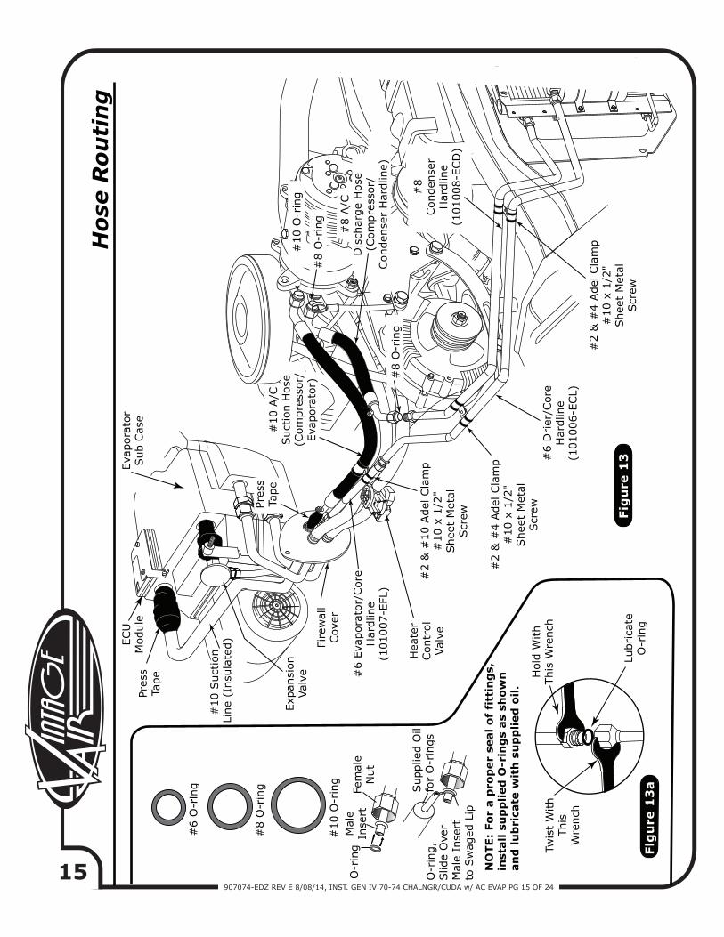
Locate the #8 compressor A/C hose. Lubricate (2) #8 O-rings (See Figure 13a, Page 15) and connect the 135° fitting to the #8 discharge port on the compressor, then route the 45° fitting to the #8 condenser hardline on the fender well (See Figure 13, Page 15). Tighten each fitting connection as shown in Figure 13a, Page 15.Locate the #10 compressor A/C hose. Lubricate (2) #10 O-rings (See Figure 13a, Page 15) and connectthe 90° fitting to the #10 suction port on the compressor, then route the straight fitting to the #10 evaporator hardline coming through the firewall (See Figure 13, Page 15). Tighten each fitting connection as shown in Figure 13a, Page 15. NOTE: Wrap the #10 fitting connections at the firewall with press tape (See Figure 13, Page 15).Locate the #6 evaporator/core hardline. Lubricate (2) #6 O-rings (See Figure 13a, Page 15) and connectthe hardline to the #6 hardline on the fender well from drier. Attach the other end of the hardline with lubricated O-ring to the #6 evaporator hardline coming through the firewall (See Figure 13, Page 15). Tighten each fitting connection as shown in Figure 13a, Page 15. Use a #2 Adel clamp to secure the #6 evaporator/core hardline to the inner fender well as shown in Figure 13, Page 15. Secure the Adel clampto the inner fender using a #10 x 1/2" sheet metal screw.
1.
2.
3.
Refer to separate instructions included with modified hose kit.1.
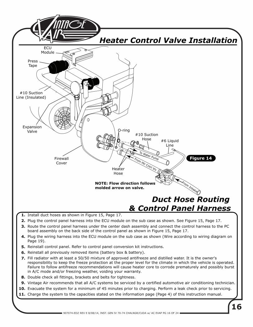
Route a piece of heater hose from the water pump to the heater line coming through the firewall as shown in Figure 13, Page 15, and Figure 14, Page 16. Secure using hose clamps.Route a piece of heater hose from the intake to the heater line coming through the firewall as shown in Figure 13, Page 15, and Figure 14, Page 16. NOTE: Install heater control valve in line with intake manifold (pressure side) heater hose. Secure using hose clamps as shown in Figure 14, Page 16. Also note proper flow direction.
1.
2.
15907074-EDZ REV E 8/08/14, INST. GEN IV 70-74 CHALNGR/CUDA w/ AC EVAP PG 15 OF 24
FIG
UR
E 8
Fig
ure
13
a
Fig
ure
13
Hos
e R
outi
ng
Pres
sTa
pe
#6
O-r
ing
Hol
d W
ithTh
is W
renc
h
O-r
ing,
Slid
e O
ver
Mal
e In
sert
to
Sw
aged
Lip
Sup
plie
d O
ilfo
r O
-rin
gs
NO
TE:
For
a p
rop
er s
eal o
f fi
ttin
gs,
inst
all s
up
plie
d O
-rin
gs
as s
how
nan
d lu
bri
cate
wit
h s
up
plie
d o
il.
Lubr
icat
eO
-rin
g
Twis
t W
ithTh
isW
renc
h
#8
O-r
ing
#10
O-r
ing
O-r
ing
Mal
eIn
sert
Fem
ale
Nut
Pres
sTa
peEx
pans
ion
Valv
e
Fire
wal
lCov
er
#2
& #
10 A
del C
lam
p#
10 x
1/2
"She
et M
etal
Scr
ew
#2
& #
4 Ade
l Cla
mp
#10
x 1
/2"
She
et M
etal
Scr
ew
#2
& #
4 Ade
l Cla
mp
#10
x 1
/2"
She
et M
etal
Scr
ew
Hea
ter
Con
trol
Valv
e
#6
Evap
orat
or/C
ore
Har
dlin
e(1
0100
7-EF
L)
#10
A/C
Suc
tion
Hos
e(C
ompr
esso
r/Ev
apor
ator
)
#8
Con
dens
erH
ardl
ine
(101
008-
ECD
)
#8
A/C
Dis
char
ge H
ose
(Com
pres
sor/
Con
dens
er H
ardl
ine)
#6
Drier
/Cor
eH
ardl
ine
(101
006-
ECL)
ECU
Mod
ule
#10
O-r
ing
#8
O-r
ing
#8
O-r
ing
Evap
orat
orSub
Cas
e
#10
Suc
tion
Lin
e (I
nsul
ated
)
16907074-EDZ REV E 8/08/14, INST. GEN IV 70-74 CHALNGR/CUDA w/ AC EVAP PG 16 OF 24
To Water Pump
ECUModule
PressTape
ExpansionValve
FirewallCover
HeaterHose
O-ring#10 Suction
Hose
NOTE: Flow direction followsmolded arrow on valve.
#6 LiquidLine
Figure 14
#10 SuctionLine (Insulated)
Heater Control Valve Installation
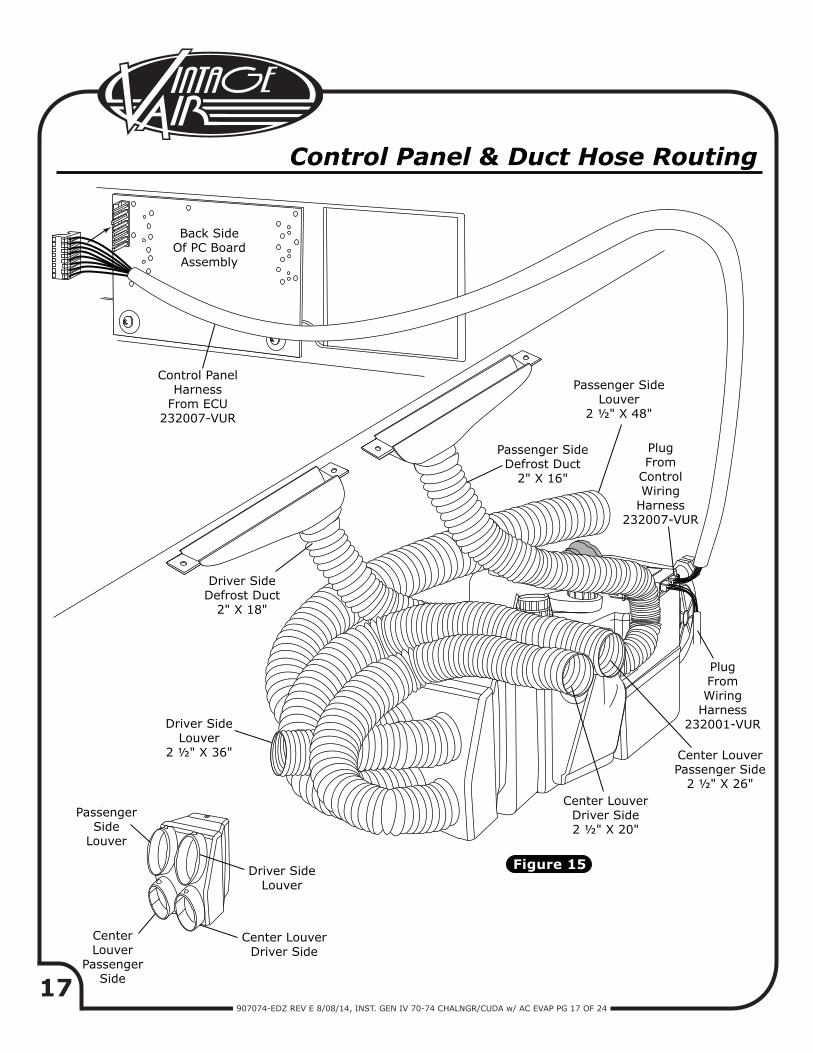
Duct Hose Routing & Control Panel Harness
Install duct hoses as shown in Figure 15, Page 17.Plug the control panel harness into the ECU module on the sub case as shown. See Figure 15, Page 17.Route the control panel harness under the center dash assembly and connect the control harness to the PC board assembly on the back side of the control panel as shown in Figure 15, Page 17.Plug the wiring harness into the ECU module on the sub case as shown (Wire according to wiring diagram on Page 19).Reinstall control panel. Refer to control panel conversion kit instructions.Reinstall all previously removed items (battery box & battery).Fill radiator with at least a 50/50 mixture of approved antifreeze and distilled water. It is the owner's responsibility to keep the freeze protection at the proper level for the climate in which the vehicle is operated. Failure to follow antifreeze recommendations will cause heater core to corrode prematurely and possibly burst in A/C mode and/or freezing weather, voiding your warranty.Double check all fittings, brackets and belts for tightness.Vintage Air recommends that all A/C systems be serviced by a certified automotive air conditioning technician.Evacuate the system for a minimum of 45 minutes prior to charging. Perform a leak check prior to servicing.Charge the system to the capacities stated on the information page (Page 4) of this instruction manual.
1. 2. 3.
4.
5. 6. 7.
8. 9.10.11.
From Intake
From Htr Cntrl Vlv
17907074-EDZ REV E 8/08/14, INST. GEN IV 70-74 CHALNGR/CUDA w/ AC EVAP PG 17 OF 24
Figure 15
Control Panel & Duct Hose Routing
Back SideOf PC BoardAssembly
Control PanelHarness
From ECU232007-VUR
Driver SideDefrost Duct
2" X 18"
Passenger SideLouver
2 ½" X 48"
Passenger SideDefrost Duct
2" X 16"
Driver SideLouver
2 ½" X 36"
PassengerSide
Louver
CenterLouver
PassengerSide
Center LouverDriver Side
Center LouverDriver Side2 ½" X 20"
Center LouverPassenger Side
2 ½" X 26"
PlugFromWiring
Harness232001-VUR
PlugFrom
ControlWiring
Harness232007-VUR
Driver SideLouver

18907074-EDZ REV E 8/08/14, INST. GEN IV 70-74 CHALNGR/CUDA w/ AC EVAP PG 18 OF 24
Fig
ure
16
Evap
orat
orH
ard
line
Inst
alla
tion
NO
TE:
Aft
er in
stal
ling
#1
0 s
uct
ion
lin
e,w
rap
all
exp
osed
met
al(f
itti
ng
s &
tu
be)
wit
h s
up
plie
dp
ress
tap
e.
Pres
s Ta
pe
Hol
d W
ithTh
is W
renc
h
Twis
t W
ithTh
isW
renc
h
Lubr
icat
e O
-rin
g(S
ee F
igur
e 13
a,Pa
ge 1
5)
Bra
cket
1804
0-VU
B3/
4" N
ylon
Spa
cer
1891
25-M
UR
1/4"
Pus
h N
utBol
t Re
tain
er
1828
9-VU
B1/
4-20
x 1
/2"
Coa
rse
Bol
tw
/ 18
125-
VU
BFl
at W
ashe
rEC
U M
odul
e
#10
O-r
ing
(338
59-V
UF)
#10
Suc
tion
Line
(091
51-P
CS)
#6
O-r
ing
(338
57-V
UF)
Hea
ter
Line
(Eva
pora
tor
to W
ater
Pum
p)09
152-
PCH
Hea
ter
Line
(Eva
pora
tor
to I
ntak
e)09
153-
PCH
#6
Liqu
id L
ine
(091
50-P
CL)
#10
O-r
ing
(338
59-V
UF)
1/4-
20 x
1/2
"Bol
t(L
ocat
ed o
nSub
Cas
e)
1/4-
20 x
1/2
"Bol
t(L
ocat
ed o
nSub
Cas
e)
Drive
r Sid
e(E
vapo
rato
r Bra
cket
)64
3531
-PCB
Pass
enge
r Sid
e(E
vapo
rato
r Bra
cket
)64
3069
-PCB
19907074-EDZ REV E 8/08/14, INST. GEN IV 70-74 CHALNGR/CUDA w/ AC EVAP PG 19 OF 24
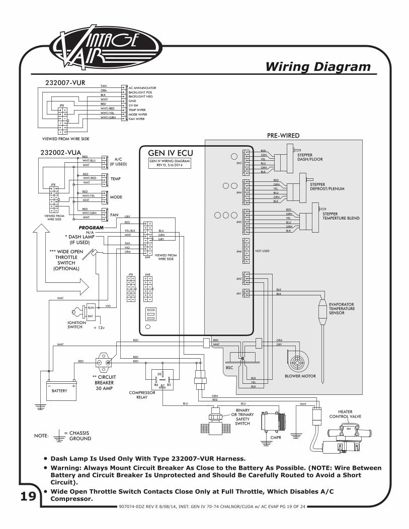
WHT/GRN
WHT/YELWHT/RED
RED
WHTBACKLIGHT NEG
FAN WIPER
MODE WIPER
TEMP WIPER
5V-SW
GND
BACKLIGHT POS
AC ANNUNCIATOR
PRE-WIRED
GEN IV WIRING DIAGRAMREV D, 5/6/2014
GEN IV ECU
PROGRAM
Wiring Diagram
TEMP
MODE
FAN
A/C(IF USED)
232007-VUR
232002-VUA
** CIRCUITBREAKER30 AMP
*** WIDE OPENTHROTTLESWITCH
(OPTIONAL)
* DASH LAMP(IF USED)
Dash Lamp Is Used Only With Type 232007-VUR Harness.Warning: Always Mount Circuit Breaker As Close to the Battery As Possible. (NOTE: Wire BetweenBattery and Circuit Breaker Is Unprotected and Should Be Carefully Routed to Avoid a ShortCircuit).Wide Open Throttle Switch Contacts Close Only at Full Throttle, Which Disables A/C Compressor.
JF8
BLK
ORA
TAN
VIEWED FROM WIRE SIDE
••
•
HEATERCONTROL VALVE
20907074-EDZ REV E 8/08/14, INST. GEN IV 70-74 CHALNGR/CUDA w/ AC EVAP PG 20 OF 24
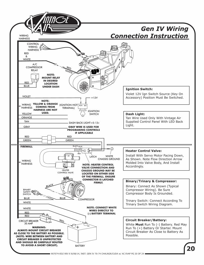
RED
CIRCUIT BREAKER30 AMP
+
+
-
BLACK
REDWHITE
RED
CHASSIS GROUND
A/CCOMPRESSOR
RELAY
Ignition Switch:
Dash Light:
NOTE: MOUNT RELAYIN DESIRED LOCATION
UNDER DASH
GREEN
FIREWALL
BLUE
BLUE
RED &
WHITE
VIOLET
(IGNITION HOTTERMINAL)
IGNITION SWITCH
DASH BACK LIGHT+0-12vTAN
GRAY
BLUE
WHITE
WHITE
REDRED
WHITE
COMPRESSOR
BATTERY
NOTE: CONNECT WHITEWIRES DIRECTLY TO
(-) BATTERY TERMINAL
BATRUN
12V
RED GREEN
RED
RED
BLUE
LATCH
BLACK
BINARYSAFETYSWITCH
YELLOW
ORANGE
WIRING HARNESS
Violet 12V Ign Switch Source (Key On Accessory) Position Must Be Switched.
Tan Wire Used Only With Vintage Air Supplied Control Panel With LED Back Light.
Binary: Connect As Shown (Typical Compressor Wiring). Be Sure Compressor Body Is Grounded.
Trinary Switch: Connect According To Trinary Switch Wiring Diagram.
Install With Servo Motor Facing Down, As Shown. Note Flow Direction Arrow Molded Into Valve Body, And Install Accordingly.
White Must Run To (-) Battery. Red May Run To (+) Battery Or Starter. Mount Circuit Breaker As Close to Battery As Possible.
Heater Control Valve:
Binary/Trinary & Compressor:
Circuit Breaker/Battery:
CONTROL WIRING HARNESS
NOTE: YELLOW & ORANGE
COMING FROM HARNESS ARE NOT
USED.
WIRING HARNESS
GRAY WIRE IS USED FOR PROGRAMING CONTROLS
IF APPLICABLE
WIRING HARNESS
Gen IV Wiring Connection Instruction
HEATERCONTROL VALVE
WARNING: ALWAYS MOUNT CIRCUIT BREAKER
AS CLOSE TO THE BATTERY AS POSSIBLE. (NOTE: WIRE BETWEEN BATTERY AND CIRCUIT BREAKER IS UNPROTECTED
AND SHOULD BE CAREFULLY ROUTED TO AVOID A SHORT CIRCUIT).
NOTE: HEATER CONTROL VALVE CONNECTION AND CHASSIS GROUND MAY BE LOCATED ON EITHER SIDE OF THE FIREWALL. ENSURECONNECTOR IS LATCHED
FIRMLY.
21907074-EDZ REV E 8/08/14, INST. GEN IV 70-74 CHALNGR/CUDA w/ AC EVAP PG 21 OF 24
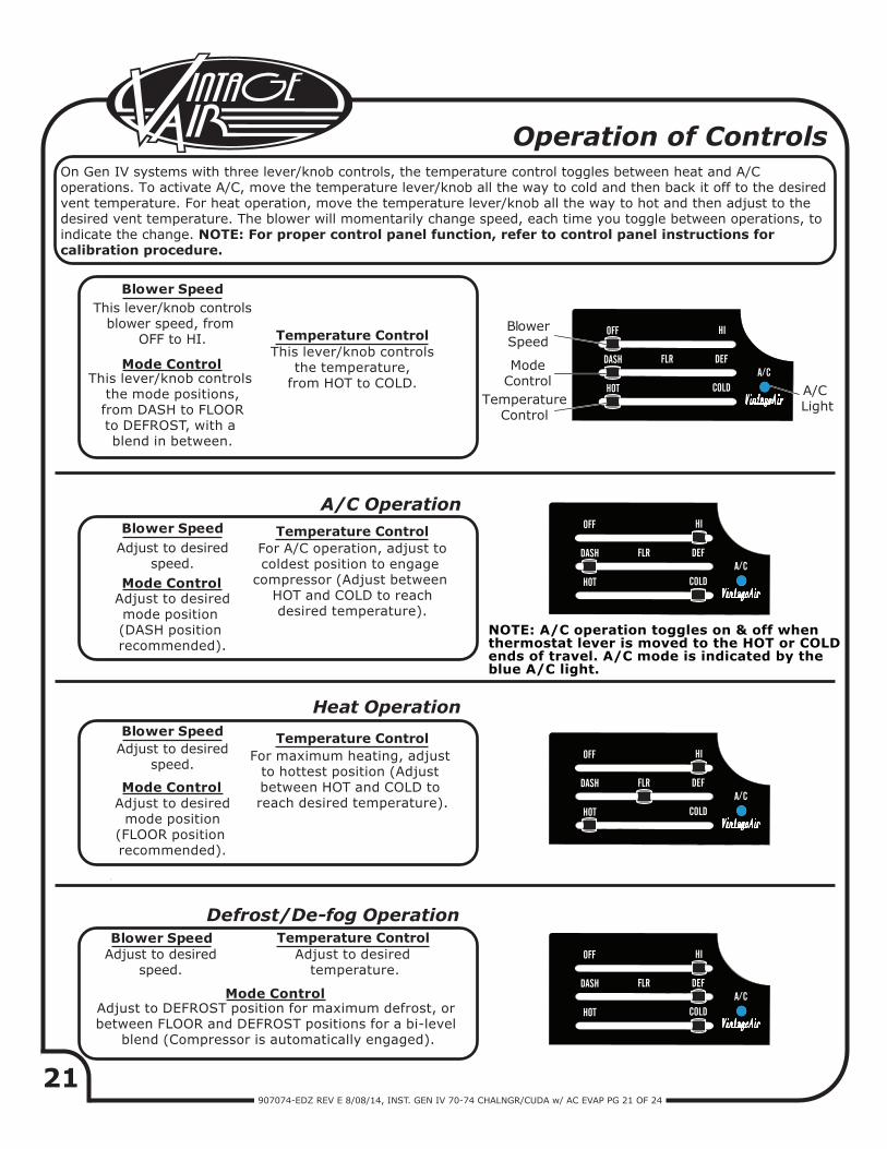
Operation of Controls
Adjust to desiredspeed.
Blower SpeedAdjust to desired
speed.
Adjust to desiredmode position (DASH position recommended).
Adjust to desiredspeed.
Adjust to DEFROST position for maximum defrost, or between FLOOR and DEFROST positions for a bi-level
blend (Compressor is automatically engaged).
Adjust to desired temperature.
For A/C operation, adjust tocoldest position to engage
compressor (Adjust between HOT and COLD to reachdesired temperature).
A/C Operation
Heat Operation
Defrost/De-fog Operation
On Gen IV systems with three lever/knob controls, the temperature control toggles between heat and A/C operations. To activate A/C, move the temperature lever/knob all the way to cold and then back it off to the desired vent temperature. For heat operation, move the temperature lever/knob all the way to hot and then adjust to the desired vent temperature. The blower will momentarily change speed, each time you toggle between operations, to indicate the change. NOTE: For proper control panel function, refer to control panel instructions for calibration procedure.
Blower Speed
Blower Speed
This lever/knob controlsblower speed, from
OFF to HI.
This lever/knob controls the mode positions,from DASH to FLOORto DEFROST, with a blend in between.
This lever/knob controlsthe temperature,
from HOT to COLD.
Blower Speed
Mode Control
Temperature Control
Temperature Control
Temperature Control
Temperature Control
Mode Control
Mode Control
Mode Control
For maximum heating, adjust to hottest position (Adjust between HOT and COLD to reach desired temperature).Adjust to desired
mode position(FLOOR position recommended).
NOTE: A/C operation toggles on & off when thermostat lever is moved to the HOT or COLD ends of travel. A/C mode is indicated by the blue A/C light.
OFF HI
DASH DEF
HOT COLD
FLRA C
A/C LightTemperature
Control
ModeControl
Blower Speed
OFF HI
DASH DEF
HOT COLD
FLRA C
OFF HI
DASH DEF
HOT COLD
FLRA C
OFF HI
DASH DEF
HOT COLD
FLRA C
22907074-EDZ REV E 8/08/14, INST. GEN IV 70-74 CHALNGR/CUDA w/ AC EVAP PG 22 OF 24
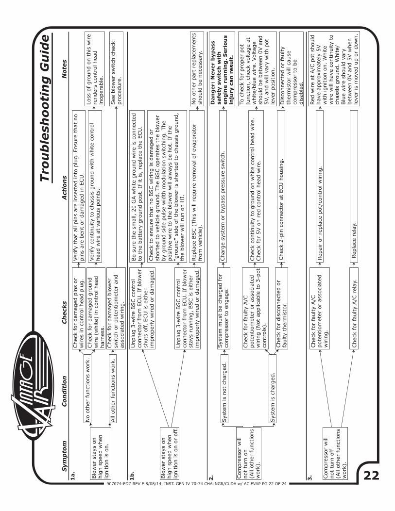
Sym
pto
m
C
on
dit
ion
C
heck
s
Act
ion
s
N
ote
s
Blo
wer
sta
ys o
n
hig
h s
pee
d w
hen
ig
nitio
n is
on.
1a.
No o
ther
funct
ions
work
.
Chec
k fo
r dam
aged
pin
s or
wires
in c
ontr
ol hea
d p
lug.
Ver
ify
that
all
pin
s ar
e in
sert
ed into
plu
g.
Ensu
re t
hat
no
pin
s ar
e ben
t or
dam
aged
in E
CU
.
Chec
k fo
r dam
aged
gro
und
wire
(white)
in c
ontr
ol hea
d
har
nes
s.
Ver
ify
continuity
to c
has
sis
gro
und w
ith w
hite
contr
ol
hea
d w
ire
at v
ario
us
poin
ts.
Loss
of gro
und o
n t
his
wire
render
s co
ntr
ol hea
d
inoper
able
.
All
oth
er f
unct
ions
work
.Chec
k fo
r dam
aged
blo
wer
sw
itch
or
pote
ntiom
eter
and
asso
ciat
ed w
irin
g.
Blo
wer
sta
ys o
n
hig
h s
pee
d w
hen
ig
nitio
n is
on o
r off.
Unplu
g 3
-wire
BSC c
ontr
ol
connec
tor
from
ECU
. If
blo
wer
sh
uts
off,
ECU
is
eith
er
impro
per
ly w
ired
or
dam
aged
.
Be
sure
the
smal
l, 2
0 G
A w
hite
gro
und w
ire
is c
onnec
ted
to t
he
bat
tery
gro
und p
ost
. If
it
is,
repla
ce t
he
ECU
.
Unplu
g 3
-wire
BSC c
ontr
ol
connec
tor
from
ECU
. If
blo
wer
st
ays
runnin
g,
BSC is
eith
er
impro
per
ly w
ired
or
dam
aged
.
Chec
k to
ensu
re t
hat
no B
SC w
irin
g is
dam
aged
or
short
ed t
o v
ehic
le g
round.
The
BSC o
per
ates
the
blo
wer
by
gro
und s
ide
puls
e w
idth
modula
tion s
witch
ing.
The
posi
tive
wire
to t
he
blo
wer
will
alw
ays
be
hot.
If th
e “g
round”
side
of
the
blo
wer
is
short
ed t
o c
has
sis
gro
und,
the
blo
wer
will
run o
n H
I.
Rep
lace
BSC (
This
will
req
uire
rem
oval
of
evap
ora
tor
from
veh
icle
).N
o o
ther
par
t re
pla
cem
ents
sh
ould
be
nec
essa
ry.
Com
pre
ssor
will
not
turn
on
(All
oth
er funct
ions
work
).
2.
Sys
tem
is
not
char
ged
.Sys
tem
must
be
char
ged
for
com
pre
ssor
to e
ngag
e.Char
ge
syst
em o
r byp
ass
pre
ssure
sw
itch
.
Dan
ger:
Never
byp
ass
sa
fety
sw
itch
wit
h
en
gin
e r
un
nin
g.
Seri
ou
s in
jury
can
resu
lt.
Sys
tem
is
char
ged
.
1b
.
Tro
ub
lesh
oo
tin
g G
uid
e
Chec
k fo
r fa
ulty
A/C
pote
ntiom
eter
or
asso
ciat
ed
wirin
g (
Not
applic
able
to 3
-pot
contr
ols
).
Chec
k fo
r dis
connec
ted o
r fa
ulty
ther
mis
tor.
Chec
k co
ntinuity
to g
round o
n w
hite
contr
ol hea
d w
ire.
Chec
k fo
r 5V o
n r
ed c
ontr
ol hea
d w
ire.
Chec
k 2-p
in c
onnec
tor
at E
CU
housi
ng.
To c
hec
k fo
r pro
per
pot
funct
ion,
chec
k vo
ltag
e at
w
hite/
blu
e w
ire.
Voltag
e sh
ould
be
bet
wee
n 0
V a
nd
5V,
and w
ill v
ary
with p
ot
leve
r posi
tion.
Dis
connec
ted o
r fa
ulty
ther
mis
tor
will
cau
se
com
pre
ssor
to b
e dis
able
d.
Red
wire
at A
/C p
ot
should
hav
e ap
pro
xim
atel
y 5V
with ignitio
n o
n.
White
wire
will
hav
e co
ntinuity
to
chas
sis
gro
und.
White/
Blu
e w
ire
should
var
y bet
wee
n 0
V a
nd 5
V w
hen
le
ver
is m
oved
up o
r dow
n.
3. Com
pre
ssor
will
not
turn
off
(A
ll oth
er funct
ions
work
).
Chec
k fo
r fa
ulty
A/C
pote
ntiom
eter
or
asso
ciat
ed
wirin
g.
Chec
k fo
r fa
ulty
A/C
rel
ay.
Rep
air
or
repla
ce p
ot/
contr
ol w
irin
g.
Rep
lace
rel
ay.
See
blo
wer
sw
itch
chec
k pro
cedure
.
23907074-EDZ REV E 8/08/14, INST. GEN IV 70-74 CHALNGR/CUDA w/ AC EVAP PG 23 OF 24
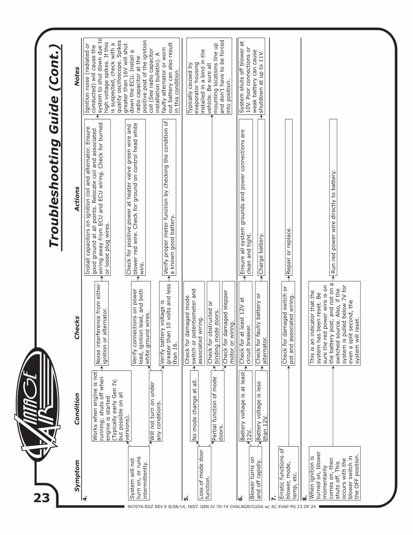
Sym
pto
m C
on
dit
ion
C
heck
s A
ctio
ns
N
ote
s
Sys
tem
will
not
turn
on,
or
runs
inte
rmitte
ntly.
4.
Work
s w
hen
engin
e is
not
runnin
g;
shuts
off
when
en
gin
e is
sta
rted
(T
ypic
ally
ear
ly G
en I
V,
but
poss
ible
on a
ll ve
rsio
ns)
.
Nois
e in
terf
eren
ce f
rom
either
ig
nitio
n o
r al
tern
ator.
Inst
all ca
pac
itors
on ignitio
n c
oil
and a
lter
nat
or. E
nsu
re
good g
round a
t al
l poin
ts.
Rel
oca
te c
oil
and a
ssoci
ated
w
irin
g a
way
fro
m E
CU
and E
CU
wirin
g.
Chec
k fo
r burn
edor
loose
plu
g w
ires
.
Ver
ify
connec
tions
on p
ow
er
lead
, ig
nitio
n lea
d,
and b
oth
white
gro
und w
ires
.
Ver
ify
pro
per
met
er f
unct
ion b
y ch
ecki
ng t
he
conditio
n o
f a
know
n g
ood b
atte
ry.
Ignitio
n n
ois
e (r
adia
ted o
rco
nduct
ed)
will
cau
se t
he
syst
em t
o s
hut
dow
n d
ue
tohig
h v
oltag
e sp
ikes
. If
this
is s
usp
ecte
d,
chec
k w
ith a
qual
ity
osc
illosc
ope.
Spik
esgre
ater
than
16V w
ill s
hut
dow
n t
he
ECU
. In
stal
l a
radio
cap
acitor
at t
he
posi
tive
post
of
the
ignitio
nco
il (S
ee r
adio
cap
acitor
inst
alla
tion b
ulle
tin).
A
faulty
alte
rnat
or
or
worn
out
bat
tery
can
als
o r
esult
in t
his
conditio
n.
Will
not
turn
on u
nder
an
y co
nditio
ns.
Ver
ify
bat
tery
voltag
e is
gre
ater
than
10 v
olts
and les
sth
an 1
6.
Loss
of
mode
door
funct
ion.
No m
ode
chan
ge
at a
ll.Chec
k fo
r dam
aged
mode
switch
or
pote
ntiom
eter
and
asso
ciat
ed w
irin
g.
Part
ial fu
nct
ion o
f m
ode
doors
.
Typic
ally
cau
sed b
y ev
apora
tor
housi
ng
inst
alle
d in a
bin
d in t
he
vehic
le.
Be
sure
all
mounting loca
tions
line
up
and d
on’t h
ave
to b
e fo
rced
in
to p
osi
tion.
Blo
wer
turn
s on
and o
ff r
apid
ly.
6.
Bat
tery
voltag
e is
at
leas
t 12V.
Chec
k fo
r at
lea
st 1
2V a
t ci
rcuit b
reak
er.
Ensu
re a
ll sy
stem
gro
unds
and p
ow
er c
onnec
tions
are
clea
n a
nd t
ight.
Bat
tery
voltag
e is
les
s th
an 1
2V.
5.
Tro
ub
lesh
oo
tin
g G
uid
e (
Co
nt.
)
Chec
k fo
r fa
ulty
bat
tery
or
alte
rnat
or.
Char
ge
bat
tery
.
Sys
tem
shuts
off
blo
wer
at
10V.
Poor
connec
tions
or
wea
k bat
tery
can
cau
se
shutd
ow
n a
t up t
o 1
1V.
7. When
ignitio
n is
turn
ed o
n,
blo
wer
m
om
enta
rily
co
mes
on,
then
sh
uts
off.
This
occ
urs
with t
he
blo
wer
sw
itch
in
the
OFF
posi
tion.
This
is
an indic
ator
that
the
syst
em h
as b
een r
eset
. Be
sure
the
red p
ow
er w
ire
is o
nth
e bat
tery
post
, an
d n
ot
on a
sw
itch
ed s
ourc
e. A
lso,
if
the
syst
em is
pulle
d b
elow
7V f
or
even
a s
plit
sec
ond,
the
syst
em w
ill r
eset
.
Run r
ed p
ow
er w
ire
direc
tly
to b
atte
ry.
Chec
k fo
r posi
tive
pow
er a
t hea
ter
valv
e gre
en w
ire
and
blo
wer
red
wire.
Chec
k fo
r gro
und o
n c
ontr
ol hea
d w
hite
wire.
Chec
k fo
r obst
ruct
ed o
r bin
din
g m
ode
doors
.
Chec
k fo
r dam
aged
ste
pper
m
oto
r or
wirin
g.
Err
atic
funct
ions
of
blo
wer
, m
ode,
te
mp,
etc.
Chec
k fo
r dam
aged
sw
itch
or
pot
and a
ssoci
ated
wirin
g.
Rep
air
or
repla
ce.
8.
907074-EDZ REV E 8/08/14, INST. GEN IV 70-74 CHALNGR/CUDA w/ AC EVAP PG 24 OF 24
Checked By:Packed By:
Date:
1.2.
11
744004-VUE784074-PMF
1
Accessory Kit784074-PMF
2
Gen IV 4-Vent Evap. Sub Case 1970-74 Challenger/Cuda with A/C Accessory Kit
NOTE: Images may not depict actual parts and quantities. Refer to packing list for actual parts and quantities.
OFF
DASH
HOT
FLR
HI
DEF
COLD
AC
Gen IV 4-VentEvap. Sub Case
744004-VUE
Packing ListEvaporator Kit (574074-EDZ)
No. Qty. Part No. Description


![INSTRUCTIONS - Speedway Motorsstatic.speedwaymotors.com/pdf/20-Circuit-Wiring-Harness... · Instructions 910-64027 ... Run the dark blue oil pressure sender wire [31] ... Run the](https://img.pdfslide.us/doc/110x75/5aacd9be7f8b9aa06a8d924e/instructions-speedway-910-64027-run-the-dark-blue-oil-pressure-sender-wire.jpg)