Embed Size (px)
Citation preview

an ISO 9001:2008 Registered Company
1967-68 Chevrolet Camaro without Factory Air
Evaporator Kit(561167)
18865 Goll St. San Antonio, TX 78266 Phone: 210-654-7171
Fax: 210-654-3113www.vintageair.com
901167 REV D 01/13/17, PG 1 OF 32
2
www.vintageair.com
901167 REV D 01/13/17, PG 2 OF 32
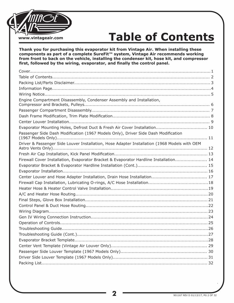
Thank you for purchasing this evaporator kit from Vintage Air. When installing these components as part of a complete SureFit™ system, Vintage Air recommends working from front to back on the vehicle, installing the condenser kit, hose kit, and compressor first, followed by the wiring, evaporator, and finally the control panel.
Cover..................................................................................................................................Table of Contents.................................................................................................................Packing List/Parts Disclaimer..................................................................................................Information Page..................................................................................................................Wiring Notice.......................................................................................................................Engine Compartment Disassembly, Condenser Assembly and Installation, Compressor and Brackets, Pulleys..........................................................................................Passenger Compartment Disassembly..................................................................................... Dash Frame Modification, Trim Plate Modification......................................................................Center Louver Installation.....................................................................................................Evaporator Mounting Holes, Defrost Duct & Fresh Air Cover Installation..................................... Passenger Side Dash Modification (1967 Models Only), Driver Side Dash Modification (1967 Models Only)............................................................................................................ Driver & Passenger Side Louver Installation, Hose Adapter Installation (1968 Models with OEM Astro Vents Only)...............................................................................................................Fresh Air Cap Installation, Kick Panel Modification................................................................... Firewall Cover Installation, Evaporator Bracket & Evaporator Hardline Installation....................... Evaporator Bracket & Evaporator Hardline Installation (Cont.).................................................. Evaporator Installation........................................................................................................ Center Louver and Hose Adapter Installation, Drain Hose Installation........................................ Firewall Cap Installation, Lubricating O-rings, A/C Hose Installation........................................... Heater Hose & Heater Control Valve Installation......................................................................A/C and Heater Hose Routing...............................................................................................Final Steps, Glove Box Installation........................................................................................Control Panel & Duct Hose Routing........................................................................................ Wiring Diagram..................................................................................................................Gen IV Wiring Connection Instruction....................................................................................Operation of Controls..........................................................................................................Troubleshooting Guide.........................................................................................................Troubleshooting Guide (Cont.)..............................................................................................Evaporator Bracket Template................................................................................................Center Vent Template (Vintage Air Louver Only).....................................................................Passenger Side Louver Template (1967 Models Only)..............................................................Driver Side Louver Template (1967 Models Only)....................................................................Packing List.......................................................................................................................
1 2 3 4 5
6 7 8 910
11
121314151617181920212223242526272829303132
Table of Contents
3
www.vintageair.com
901167 REV D 01/13/17, PG 3 OF 32
FAN
OFF
COLD
OFF
AIR
TEM PERATURE
DEFROST
HOT
ON
DE-ICE
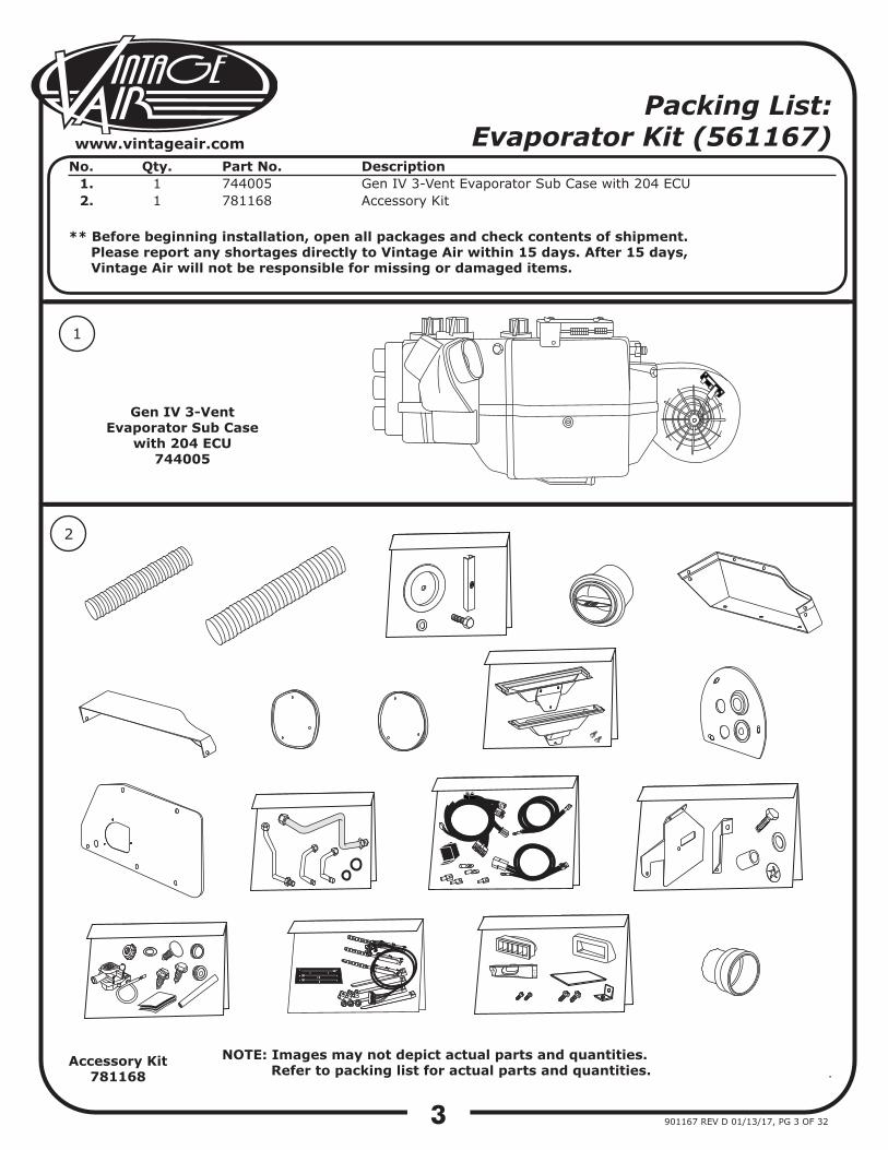
Packing List: Evaporator Kit (561167)
No. 1.2.
Qty.11
Part No.744005781168
DescriptionGen IV 3-Vent Evaporator Sub Case with 204 ECUAccessory Kit
** Before beginning installation, open all packages and check contents of shipment. Please report any shortages directly to Vintage Air within 15 days. After 15 days, Vintage Air will not be responsible for missing or damaged items.
NOTE: Images may not depict actual parts and quantities. Refer to packing list for actual parts and quantities.
1
2
Gen IV 3-Vent Evaporator Sub Case
with 204 ECU744005
Accessory Kit781168
4
www.vintageair.com
901167 REV D 01/13/17, PG 4 OF 32
Important Notice—Please ReadFor Maximum System Performance, Vintage Air Recommends the Following:
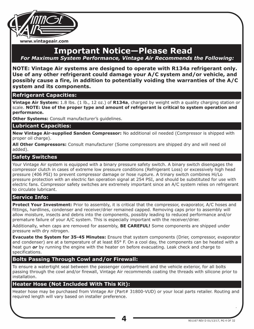
New Vintage Air-supplied Sanden Compressor: No additional oil needed (Compressor is shipped with proper oil charge).All Other Compressors: Consult manufacturer (Some compressors are shipped dry and will need oil added).
NOTE: Vintage Air systems are designed to operate with R134a refrigerant only. Use of any other refrigerant could damage your A/C system and/or vehicle, and possibly cause a fire, in addition to potentially voiding the warranties of the A/C system and its components.
Refrigerant Capacities:Vintage Air System: 1.8 lbs. (1 lb., 12 oz.) of R134a, charged by weight with a quality charging station or scale. NOTE: Use of the proper type and amount of refrigerant is critical to system operation and performance.Other Systems: Consult manufacturer’s guidelines.
Lubricant Capacities:
Safety Switches
Service Info:Protect Your Investment: Prior to assembly, it is critical that the compressor, evaporator, A/C hoses and fittings, hardlines, condenser and receiver/drier remained capped. Removing caps prior to assembly will allow moisture, insects and debris into the components, possibly leading to reduced performance and/or premature failure of your A/C system. This is especially important with the receiver/drier. Additionally, when caps are removed for assembly, BE CAREFUL! Some components are shipped under pressure with dry nitrogen.Evacuate the System for 35-45 Minutes: Ensure that system components (Drier, compressor, evaporator and condenser) are at a temperature of at least 85° F. On a cool day, the components can be heated with a heat gun or by running the engine with the heater on before evacuating. Leak check and charge to specifications.
Your Vintage Air system is equipped with a binary pressure safety switch. A binary switch disengages the compressor clutch in cases of extreme low pressure conditions (Refrigerant Loss) or excessively high head pressure (406 PSI) to prevent compressor damage or hose rupture. A trinary switch combines Hi/Lo pressure protection with an electric fan operation signal at 254 PSI, and should be substituted for use with electric fans. Compressor safety switches are extremely important since an A/C system relies on refrigerant to circulate lubricant.
Bolts Passing Through Cowl and/or Firewall:To ensure a watertight seal between the passenger compartment and the vehicle exterior, for all bolts passing through the cowl and/or firewall, Vintage Air recommends coating the threads with silicone prior to installation.
Heater Hose (Not Included With This Kit):Heater hose may be purchased from Vintage Air (Part# 31800-VUD) or your local parts retailer. Routing and required length will vary based on installer preference.
5
www.vintageair.com
901167 REV D 01/13/17, PG 5 OF 32
Important Wiring Notice—Please Read
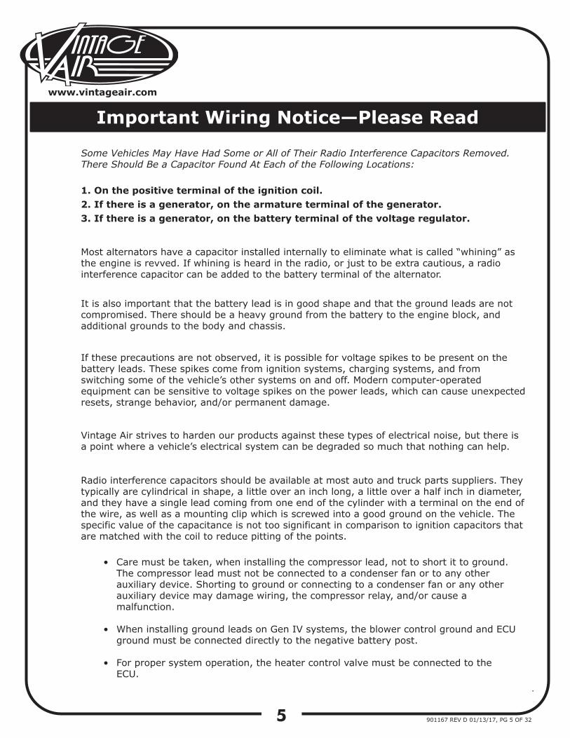
Some Vehicles May Have Had Some or All of Their Radio Interference Capacitors Removed. There Should Be a Capacitor Found At Each of the Following Locations:
1. On the positive terminal of the ignition coil.2. If there is a generator, on the armature terminal of the generator.3. If there is a generator, on the battery terminal of the voltage regulator.
Most alternators have a capacitor installed internally to eliminate what is called “whining” as the engine is revved. If whining is heard in the radio, or just to be extra cautious, a radio interference capacitor can be added to the battery terminal of the alternator.
It is also important that the battery lead is in good shape and that the ground leads are not compromised. There should be a heavy ground from the battery to the engine block, and additional grounds to the body and chassis.
If these precautions are not observed, it is possible for voltage spikes to be present on the battery leads. These spikes come from ignition systems, charging systems, and from switching some of the vehicle’s other systems on and off. Modern computer-operated equipment can be sensitive to voltage spikes on the power leads, which can cause unexpected resets, strange behavior, and/or permanent damage.
Vintage Air strives to harden our products against these types of electrical noise, but there is a point where a vehicle’s electrical system can be degraded so much that nothing can help.
Radio interference capacitors should be available at most auto and truck parts suppliers. They typically are cylindrical in shape, a little over an inch long, a little over a half inch in diameter, and they have a single lead coming from one end of the cylinder with a terminal on the end of the wire, as well as a mounting clip which is screwed into a good ground on the vehicle. The specific value of the capacitance is not too significant in comparison to ignition capacitors that are matched with the coil to reduce pitting of the points.
Care must be taken, when installing the compressor lead, not to short it to ground. The compressor lead must not be connected to a condenser fan or to any other auxiliary device. Shorting to ground or connecting to a condenser fan or any other auxiliary device may damage wiring, the compressor relay, and/or cause a malfunction.
When installing ground leads on Gen IV systems, the blower control ground and ECU ground must be connected directly to the negative battery post.
For proper system operation, the heater control valve must be connected to the ECU.
•
•
•
6
www.vintageair.com
901167 REV D 01/13/17, PG 6 OF 32
Engine Compartment Disassembly
1.2.3.4.5.6.
7.8.
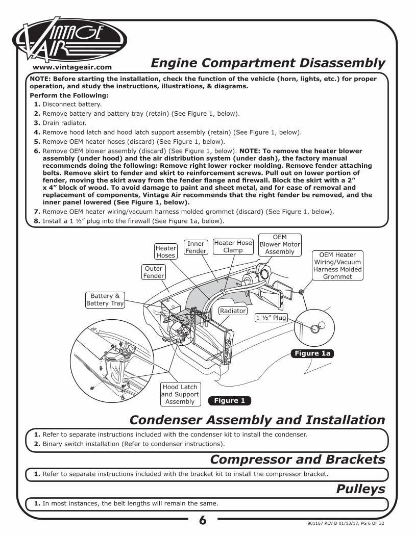
Disconnect battery.Remove battery and battery tray (retain) (See Figure 1, below).Drain radiator.Remove hood latch and hood latch support assembly (retain) (See Figure 1, below).Remove OEM heater hoses (discard) (See Figure 1, below).Remove OEM blower assembly (discard) (See Figure 1, below). NOTE: To remove the heater blower assembly (under hood) and the air distribution system (under dash), the factory manual recommends doing the following: Remove right lower rocker molding. Remove fender attaching bolts. Remove skirt to fender and skirt to reinforcement screws. Pull out on lower portion of fender, moving the skirt away from the fender flange and firewall. Block the skirt with a 2” x 4” block of wood. To avoid damage to paint and sheet metal, and for ease of removal and replacement of components, Vintage Air recommends that the right fender be removed, and the inner panel lowered (See Figure 1, below).Remove OEM heater wiring/vacuum harness molded grommet (discard) (See Figure 1, below).Install a 1 ½” plug into the firewall (See Figure 1a, below).
NOTE: Before starting the installation, check the function of the vehicle (horn, lights, etc.) for proper operation, and study the instructions, illustrations, & diagrams.Perform the Following:
Figure 1
Condenser Assembly and Installation1.2.
Refer to separate instructions included with the condenser kit to install the condenser.Binary switch installation (Refer to condenser instructions).
Compressor and Brackets1. Refer to separate instructions included with the bracket kit to install the compressor bracket.
Pulleys1. In most instances, the belt lengths will remain the same.
Figure 1a
Hood Latchand Support
Assembly
Radiator
HeaterHoses
Heater HoseClamp
OEMBlower Motor
Assembly OEM HeaterWiring/Vacuum Harness Molded
GrommetOuterFender
Inner Fender
Battery &Battery Tray
1 ½” Plug
7
www.vintageair.com
901167 REV D 01/13/17, PG 7 OF 32
Passenger Compartment Disassembly
1.
2.3.4.5.6.7.8.9.
10.11.12.13.
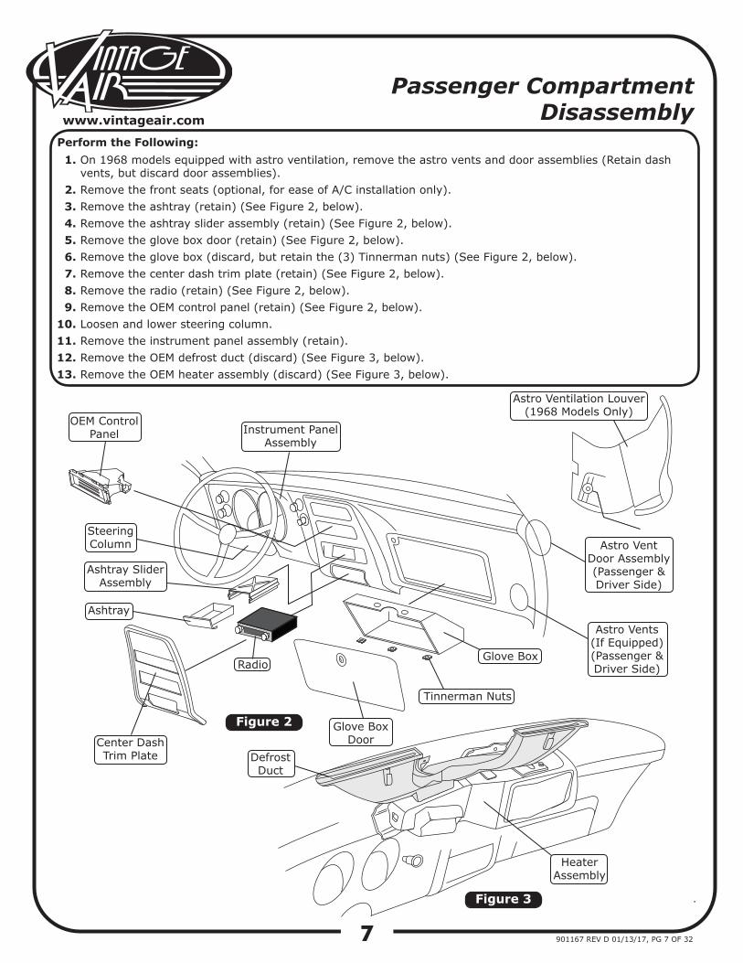
On 1968 models equipped with astro ventilation, remove the astro vents and door assemblies (Retain dash vents, but discard door assemblies).Remove the front seats (optional, for ease of A/C installation only).Remove the ashtray (retain) (See Figure 2, below).Remove the ashtray slider assembly (retain) (See Figure 2, below).Remove the glove box door (retain) (See Figure 2, below).Remove the glove box (discard, but retain the (3) Tinnerman nuts) (See Figure 2, below).Remove the center dash trim plate (retain) (See Figure 2, below).Remove the radio (retain) (See Figure 2, below).Remove the OEM control panel (retain) (See Figure 2, below).Loosen and lower steering column.Remove the instrument panel assembly (retain).Remove the OEM defrost duct (discard) (See Figure 3, below).Remove the OEM heater assembly (discard) (See Figure 3, below).
Perform the Following:
Figure 2
Figure 3
Astro Ventilation Louver(1968 Models Only)
Astro VentDoor Assembly(Passenger & Driver Side)
Astro Vents(If Equipped)(Passenger & Driver Side)
Instrument PanelAssembly
OEM Control Panel
SteeringColumn
Ashtray Slider Assembly
Ashtray
Center DashTrim Plate
Radio
Glove BoxDoor
Tinnerman Nuts
Glove Box
Defrost Duct
Heater Assembly
8
www.vintageair.com
901167 REV D 01/13/17, PG 8 OF 32
Dash Frame Modification
Trim Plate Modification
1.
1.
2.
3.
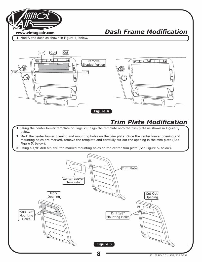
Modify the dash as shown in Figure 4, below.
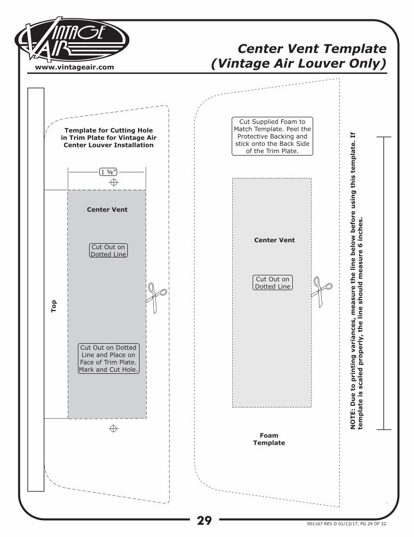
Using the center louver template on Page 29, align the template onto the trim plate as shown in Figure 5, below.Mark the center louver opening and mounting holes on the trim plate. Once the center louver opening and mounting holes are marked, remove the template and carefully cut out the opening in the trim plate (See Figure 5, below).Using a 1/8” drill bit, drill the marked mounting holes on the center trim plate (See Figure 5, below).
Figure 4
Figure 5
Cut Cut Cut
CutCut
Remove Shaded Portion
Center Louver Template
Trim Plate
Mark Opening
Mark 1/8” Mounting
Holes
Drill 1/8”Mounting Holes
Cut Out Opening
9
www.vintageair.com
901167 REV D 01/13/17, PG 9 OF 32
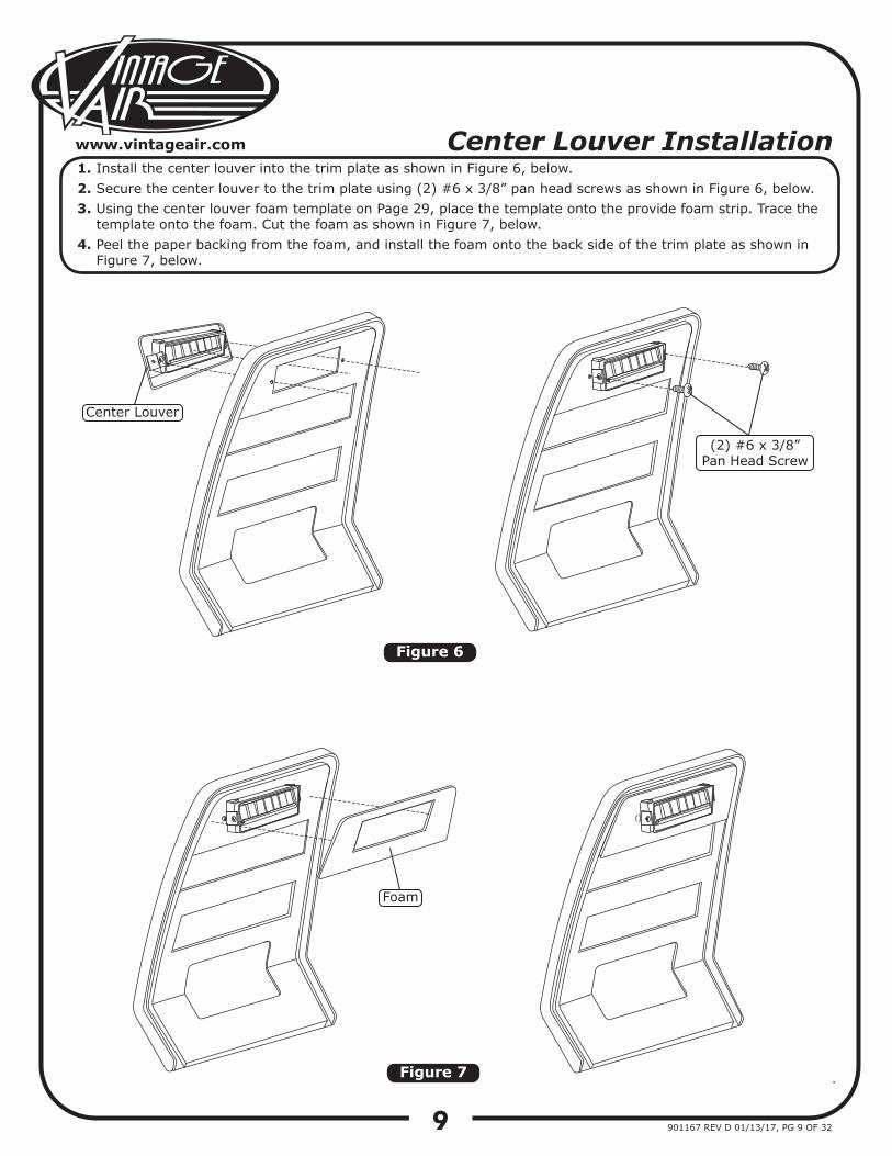
Center Louver Installation1.2.3.
4.
Install the center louver into the trim plate as shown in Figure 6, below.Secure the center louver to the trim plate using (2) #6 x 3/8” pan head screws as shown in Figure 6, below.Using the center louver foam template on Page 29, place the template onto the provide foam strip. Trace the template onto the foam. Cut the foam as shown in Figure 7, below.Peel the paper backing from the foam, and install the foam onto the back side of the trim plate as shown in Figure 7, below.
Figure 6
Figure 7
Center Louver
(2) #6 x 3/8”Pan Head Screw
Foam
10
www.vintageair.com
901167 REV D 01/13/17, PG 10 OF 32
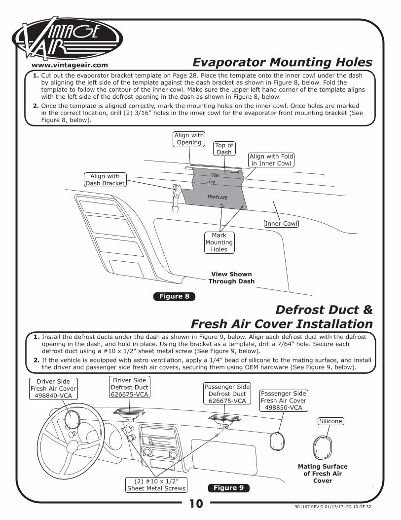
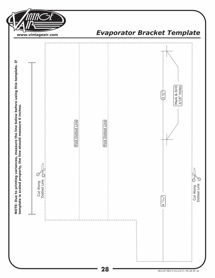
Evaporator Mounting Holes1.
2.
Cut out the evaporator bracket template on Page 28. Place the template onto the inner cowl under the dash by aligning the left side of the template against the dash bracket as shown in Figure 8, below. Fold the template to follow the contour of the inner cowl. Make sure the upper left hand corner of the template aligns with the left side of the defrost opening in the dash as shown in Figure 8, below.Once the template is aligned correctly, mark the mounting holes on the inner cowl. Once holes are marked in the correct location, drill (2) 3/16” holes in the inner cowl for the evaporator front mounting bracket (See Figure 8, below).
Figure 9
Figure 8
Defrost Duct & Fresh Air Cover Installation
1.
2.
Install the defrost ducts under the dash as shown in Figure 9, below. Align each defrost duct with the defrost opening in the dash, and hold in place. Using the bracket as a template, drill a 7/64” hole. Secure each defrost duct using a #10 x 1/2” sheet metal screw (See Figure 9, below).If the vehicle is equipped with astro ventilation, apply a 1/4” bead of silicone to the mating surface, and install the driver and passenger side fresh air covers, securing them using OEM hardware (See Figure 9, below).
FOLD
FOLD
TEMPLATE
Align with Dash Bracket
Align with Opening Top of
DashAlign with Fold in Inner Cowl
Mark Mounting
Holes
Inner Cowl
View ShownThrough Dash
Driver SideFresh Air Cover
498840-VCA Passenger SideFresh Air Cover
498850-VCA
(2) #10 x 1/2” Sheet Metal Screws
Driver SideDefrost Duct626675-VCA
Passenger SideDefrost Duct626675-VCA
Mating Surfaceof Fresh Air
Cover
Silicone
11
www.vintageair.com
901167 REV D 01/13/17, PG 11 OF 32
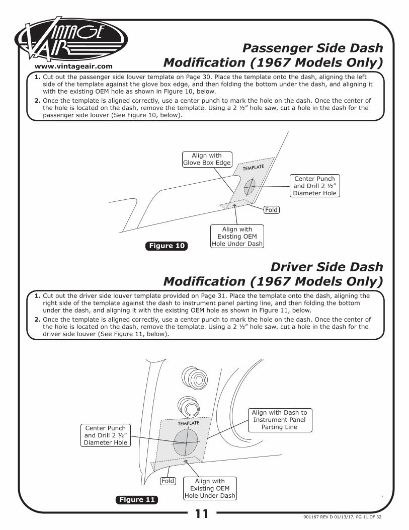
Passenger Side Dash Modification (1967 Models Only)
Driver Side Dash Modification (1967 Models Only)
1.
2.
1.
2.
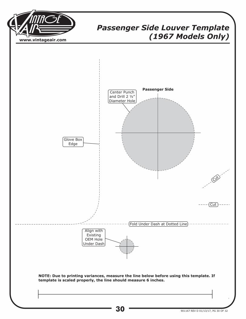
Cut out the passenger side louver template on Page 30. Place the template onto the dash, aligning the left side of the template against the glove box edge, and then folding the bottom under the dash, and aligning it with the existing OEM hole as shown in Figure 10, below.Once the template is aligned correctly, use a center punch to mark the hole on the dash. Once the center of the hole is located on the dash, remove the template. Using a 2 ½” hole saw, cut a hole in the dash for the passenger side louver (See Figure 10, below).
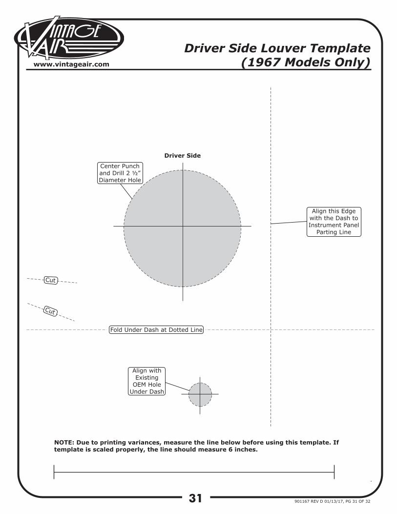
Cut out the driver side louver template provided on Page 31. Place the template onto the dash, aligning the right side of the template against the dash to instrument panel parting line, and then folding the bottom under the dash, and aligning it with the existing OEM hole as shown in Figure 11, below.Once the template is aligned correctly, use a center punch to mark the hole on the dash. Once the center of the hole is located on the dash, remove the template. Using a 2 ½” hole saw, cut a hole in the dash for the driver side louver (See Figure 11, below).
Figure 10
Figure 11
TEMPLATE
TEMPLATE
Align with Glove Box Edge
Fold
Fold
Align withExisting OEM
Hole Under Dash
Align withExisting OEM
Hole Under Dash
Center Punchand Drill 2 ½”Diameter Hole
Center Punchand Drill 2 ½”Diameter Hole
Align with Dash to Instrument Panel
Parting Line
12
www.vintageair.com
901167 REV D 01/13/17, PG 12 OF 32
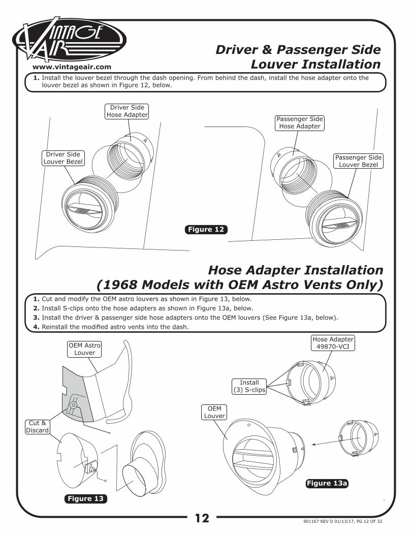
Driver & Passenger Side Louver Installation
Hose Adapter Installation(1968 Models with OEM Astro Vents Only)
1.
1.2.3.4.
Install the louver bezel through the dash opening. From behind the dash, install the hose adapter onto the louver bezel as shown in Figure 12, below.
Cut and modify the OEM astro louvers as shown in Figure 13, below.Install S-clips onto the hose adapters as shown in Figure 13a, below.Install the driver & passenger side hose adapters onto the OEM louvers (See Figure 13a, below).Reinstall the modified astro vents into the dash.
Figure 12
Figure 13a
Figure 13
Driver SideHose Adapter
Passenger SideHose Adapter
Driver SideLouver Bezel
Passenger SideLouver Bezel
OEM AstroLouver
Cut &Discard
OEMLouver
Install(3) S-clips
Hose Adapter49870-VCI
13
www.vintageair.com
901167 REV D 01/13/17, PG 13 OF 32
Figure 14
Figure 15 Figure 15a
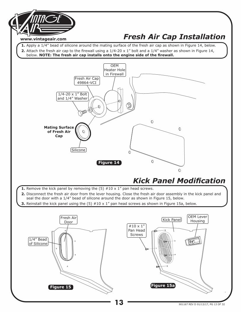
Fresh Air Cap Installation
Kick Panel Modification
1.2.
1.2.
3.
Apply a 1/4” bead of silicone around the mating surface of the fresh air cap as shown in Figure 14, below.Attach the fresh air cap to the firewall using a 1/4-20 x 1” bolt and a 1/4” washer as shown in Figure 14, below. NOTE: The fresh air cap installs onto the engine side of the firewall.
Remove the kick panel by removing the (5) #10 x 1” pan head screws.Disconnect the fresh air door from the lever housing. Close the fresh air door assembly in the kick panel and seal the door with a 1/4” bead of silicone around the door as shown in Figure 15, below.Reinstall the kick panel using the (5) #10 x 1” pan head screws as shown in Figure 15a, below.
Fresh Air Cap49864-VCI
1/4-20 x 1” Bolt and 1/4” Washer
Mating Surfaceof Fresh Air
Cap
Silicone
OEMHeater Holein Firewall
Fresh Air Door
1/4” Beadof Silicone
#10 x 1”Pan HeadScrews
Kick PanelOEM LeverHousing
14
www.vintageair.com
901167 REV D 01/13/17, PG 14 OF 32
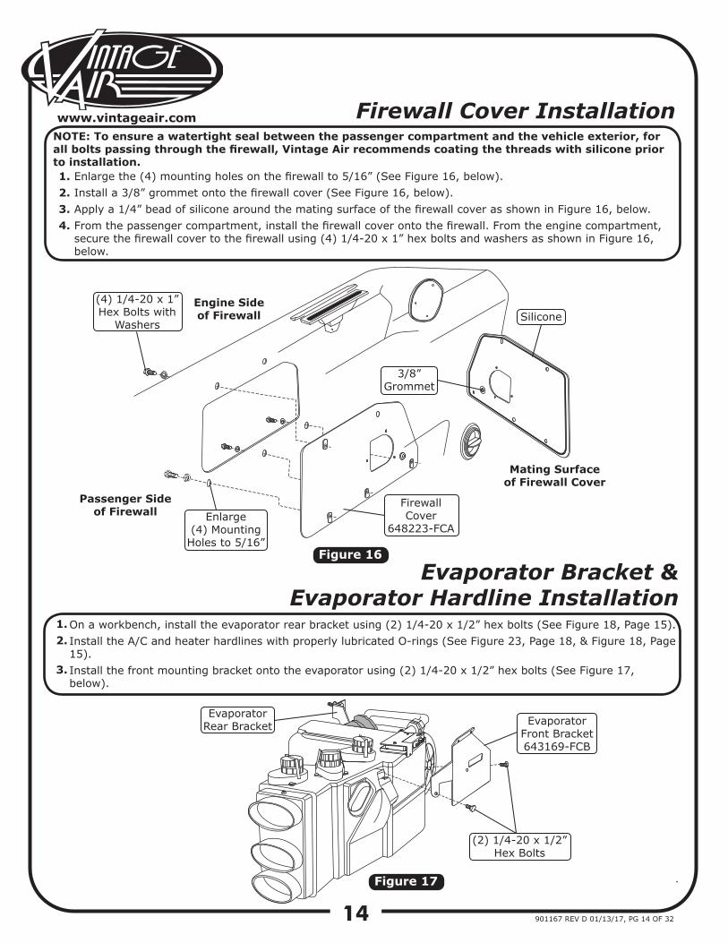
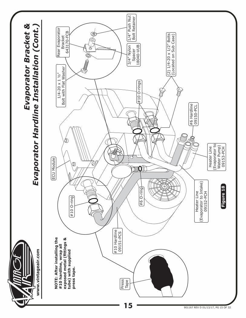
Evaporator Bracket & Evaporator Hardline Installation
1.2.
3.
On a workbench, install the evaporator rear bracket using (2) 1/4-20 x 1/2” hex bolts (See Figure 18, Page 15).Install the A/C and heater hardlines with properly lubricated O-rings (See Figure 23, Page 18, & Figure 18, Page 15).Install the front mounting bracket onto the evaporator using (2) 1/4-20 x 1/2” hex bolts (See Figure 17, below).
Figure 16
Figure 17
Firewall Cover Installation
1.2.3.4.
Enlarge the (4) mounting holes on the firewall to 5/16” (See Figure 16, below).Install a 3/8” grommet onto the firewall cover (See Figure 16, below).Apply a 1/4” bead of silicone around the mating surface of the firewall cover as shown in Figure 16, below.From the passenger compartment, install the firewall cover onto the firewall. From the engine compartment, secure the firewall cover to the firewall using (4) 1/4-20 x 1” hex bolts and washers as shown in Figure 16, below.
(4) 1/4-20 x 1”Hex Bolts with
WashersSilicone
Mating Surfaceof Firewall Cover
Firewall Cover
648223-FCAEnlarge
(4) Mounting Holes to 5/16”
Engine Sideof Firewall
Passenger Sideof Firewall
Evaporator Rear Bracket Evaporator
Front Bracket643169-FCB
(2) 1/4-20 x 1/2”Hex Bolts
NOTE: To ensure a watertight seal between the passenger compartment and the vehicle exterior, for all bolts passing through the firewall, Vintage Air recommends coating the threads with silicone prior to installation.
3/8” Grommet
ww
w.v
inta
gea
ir.c
om
15 901167 REV D 01/13/17, PG 15 OF 32
Evap
orat
or B
rack
et &
Ev
apor
ator
Har
dlin
e In
stal
lati
on (
Con
t.)
Fig
ure
18
(2)
1/4-
20 x
1/2
” Bol
ts(L
ocat
ed o
n Sub
Cas
e)
Rear
Eva
pora
tor
Bra
cket
6431
70-F
CB
1/4-
20 x
1 ½
”Bol
t w
ith F
lat
Was
her
3/4”
Nyl
onSpa
cer
1804
0-VU
B
1/4”
Pus
h N
utBol
t Re
tain
er#
10 O
-rin
gs
#10
O-r
ing
#6
O-r
ing
Pres
sTa
pe
#10
Har
dlin
e09
151-
PCS
#6
Har
dlin
e09
150-
PCL
Hea
ter
Line
(Eva
pora
tor
to I
ntak
e)09
152-
PCH
Hea
ter
Line
(Eva
pora
tor
to
Wat
er P
ump)
0915
3-PC
H
ECU
Mod
ule
NO
TE:
Aft
er in
stal
ling
th
e #
10
har
dlin
e, w
rap
all
exp
osed
met
al (
fitt
ing
s &
tu
be)
wit
h s
up
plie
d
pre
ss t
ape.
16
www.vintageair.com
901167 REV D 01/13/17, PG 16 OF 32
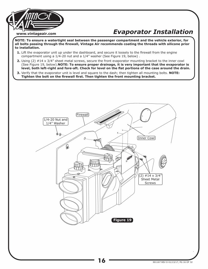
Evaporator Installation
1.
2.
3.
Lift the evaporator unit up under the dashboard, and secure it loosely to the firewall from the engine compartment using a 1/4-20 nut and a 1/4” washer (See Figure 19, below) . Using (2) #14 x 3/4” sheet metal screws, secure the front evaporator mounting bracket to the inner cowl (See Figure 19, below).NOTE: To ensure proper drainage, it is very important that the evaporator is level, both left-right and fore-aft. Check for level on the flat portions of the case around the drain.Verify that the evaporator unit is level and square to the dash; then tighten all mounting bolts. NOTE: Tighten the bolt on the firewall first. Then tighten the front mounting bracket.
NOTE: To ensure a watertight seal between the passenger compartment and the vehicle exterior, for all bolts passing through the firewall, Vintage Air recommends coating the threads with silicone prior to installation.
Figure 19
1/4-20 Nut and 1/4” Washer
Firewall
Inner Cowl
(2) #14 x 3/4”Sheet Metal
Screws
17
www.vintageair.com
901167 REV D 01/13/17, PG 17 OF 32
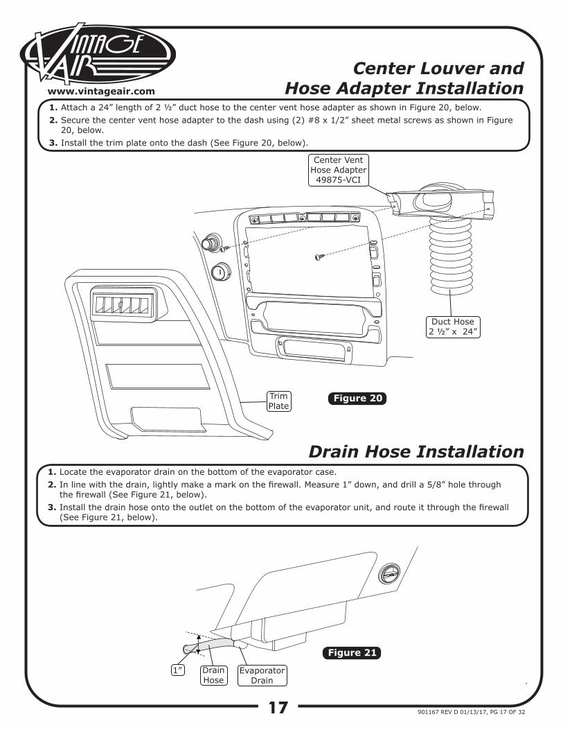
Center Louver and Hose Adapter Installation
1.2.
3.
Attach a 24” length of 2 ½” duct hose to the center vent hose adapter as shown in Figure 20, below.Secure the center vent hose adapter to the dash using (2) #8 x 1/2” sheet metal screws as shown in Figure 20, below.Install the trim plate onto the dash (See Figure 20, below).
Figure 20
Figure 21
Drain Hose Installation1.2.
3.
Locate the evaporator drain on the bottom of the evaporator case.In line with the drain, lightly make a mark on the firewall. Measure 1” down, and drill a 5/8” hole through the firewall (See Figure 21, below).Install the drain hose onto the outlet on the bottom of the evaporator unit, and route it through the firewall (See Figure 21, below).
TrimPlate
Duct Hose2 ½” x 24”
Center VentHose Adapter49875-VCI
1” DrainHose
EvaporatorDrain
18
www.vintageair.com
901167 REV D 01/13/17, PG 18 OF 32
Figure 22
A/C Hose Installation
1.
2.
3.
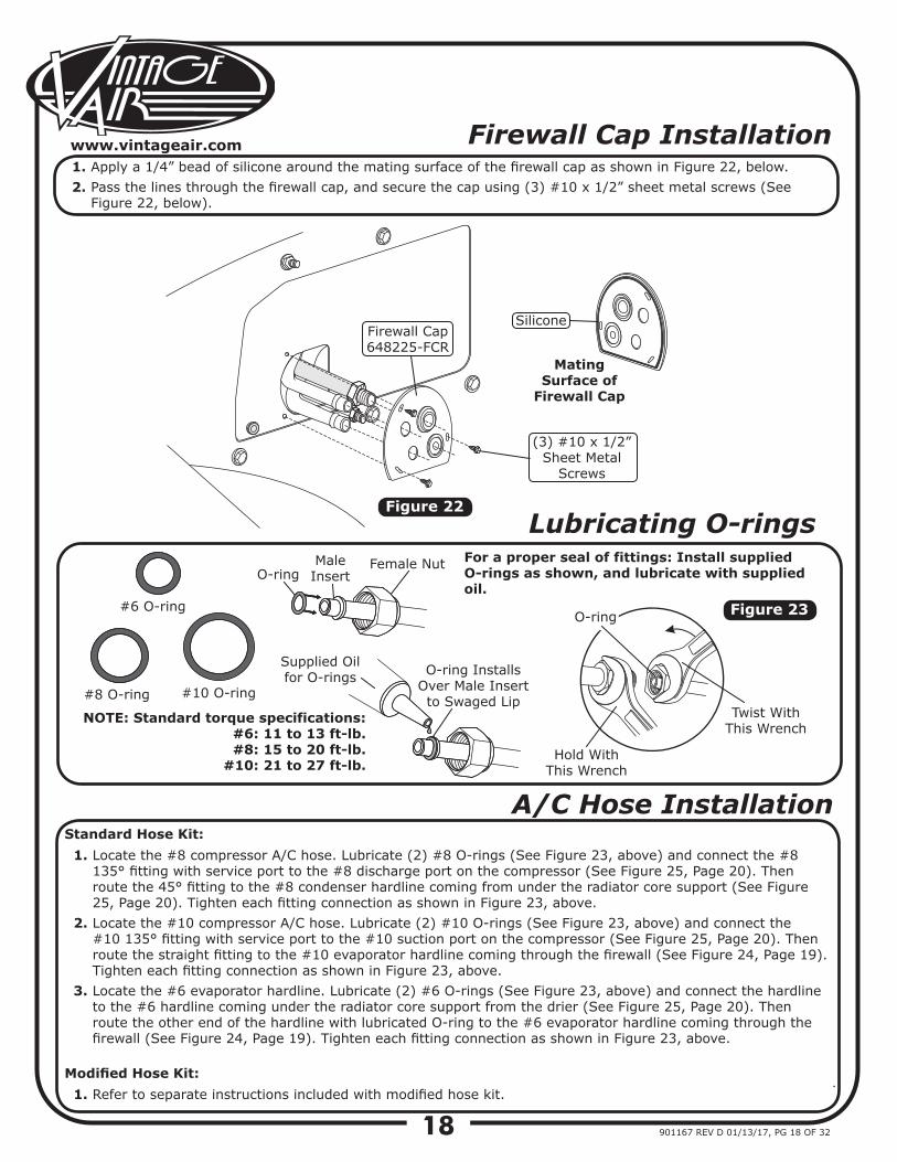
Locate the #8 compressor A/C hose. Lubricate (2) #8 O-rings (See Figure 23, above) and connect the #8 135° fitting with service port to the #8 discharge port on the compressor (See Figure 25, Page 20). Then route the 45° fitting to the #8 condenser hardline coming from under the radiator core support (See Figure 25, Page 20). Tighten each fitting connection as shown in Figure 23, above.Locate the #10 compressor A/C hose. Lubricate (2) #10 O-rings (See Figure 23, above) and connect the #10 135° fitting with service port to the #10 suction port on the compressor (See Figure 25, Page 20). Then route the straight fitting to the #10 evaporator hardline coming through the firewall (See Figure 24, Page 19). Tighten each fitting connection as shown in Figure 23, above.Locate the #6 evaporator hardline. Lubricate (2) #6 O-rings (See Figure 23, above) and connect the hardline to the #6 hardline coming under the radiator core support from the drier (See Figure 25, Page 20). Then route the other end of the hardline with lubricated O-ring to the #6 evaporator hardline coming through the firewall (See Figure 24, Page 19). Tighten each fitting connection as shown in Figure 23, above.
Standard Hose Kit:
1. Refer to separate instructions included with modified hose kit.Modified Hose Kit:
Figure ##
O-ring Installs Over Male Insert to Swaged Lip
O-ring#6 O-ring
#8 O-ring #10 O-ring
O-ring
Supplied Oil for O-rings
Male Insert
Female Nut
Hold With This Wrench
Twist With This Wrench
Lubricating O-rings For a proper seal of fittings: Install supplied O-rings as shown, and lubricate with supplied oil.
NOTE: Standard torque specifications:#6: 11 to 13 ft-lb.#8: 15 to 20 ft-lb.
#10: 21 to 27 ft-lb.
Figure 23
Firewall Cap Installation1.2.
Apply a 1/4” bead of silicone around the mating surface of the firewall cap as shown in Figure 22, below.Pass the lines through the firewall cap, and secure the cap using (3) #10 x 1/2” sheet metal screws (See Figure 22, below).
Mating Surface of
Firewall Cap
SiliconeFirewall Cap648225-FCR
(3) #10 x 1/2”Sheet Metal
Screws
19
www.vintageair.com
901167 REV D 01/13/17, PG 19 OF 32
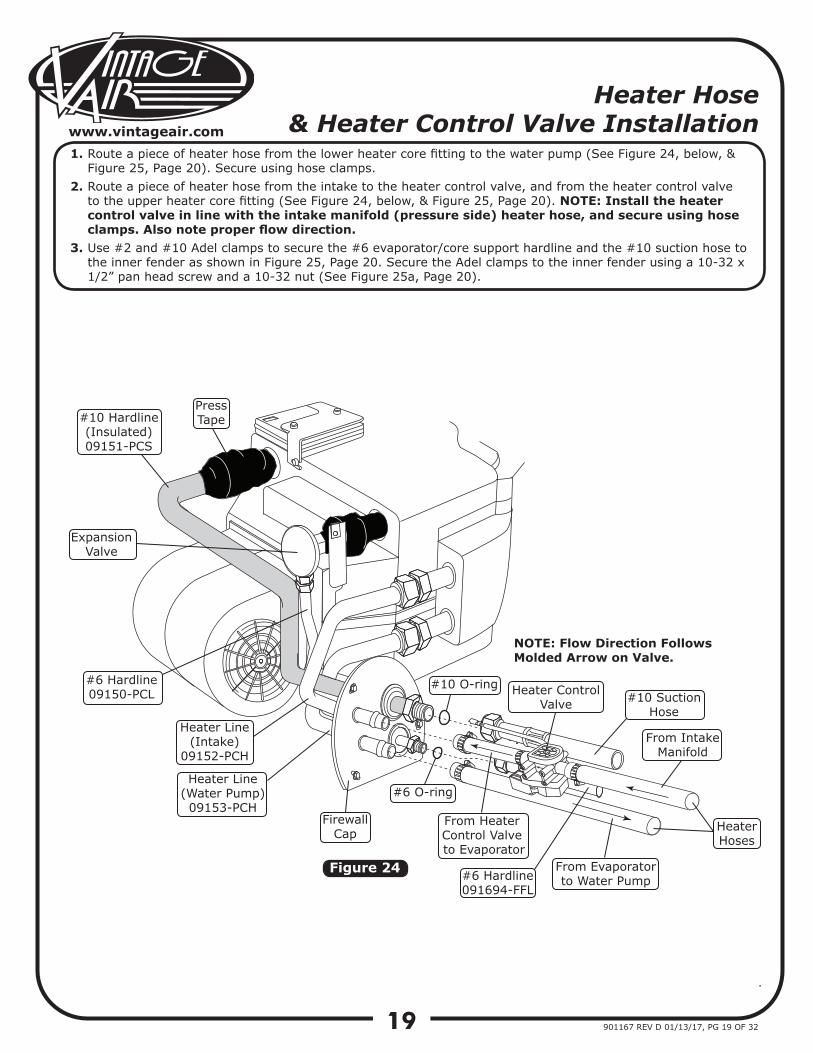
Heater Hose & Heater Control Valve Installation
1.
2.
3.
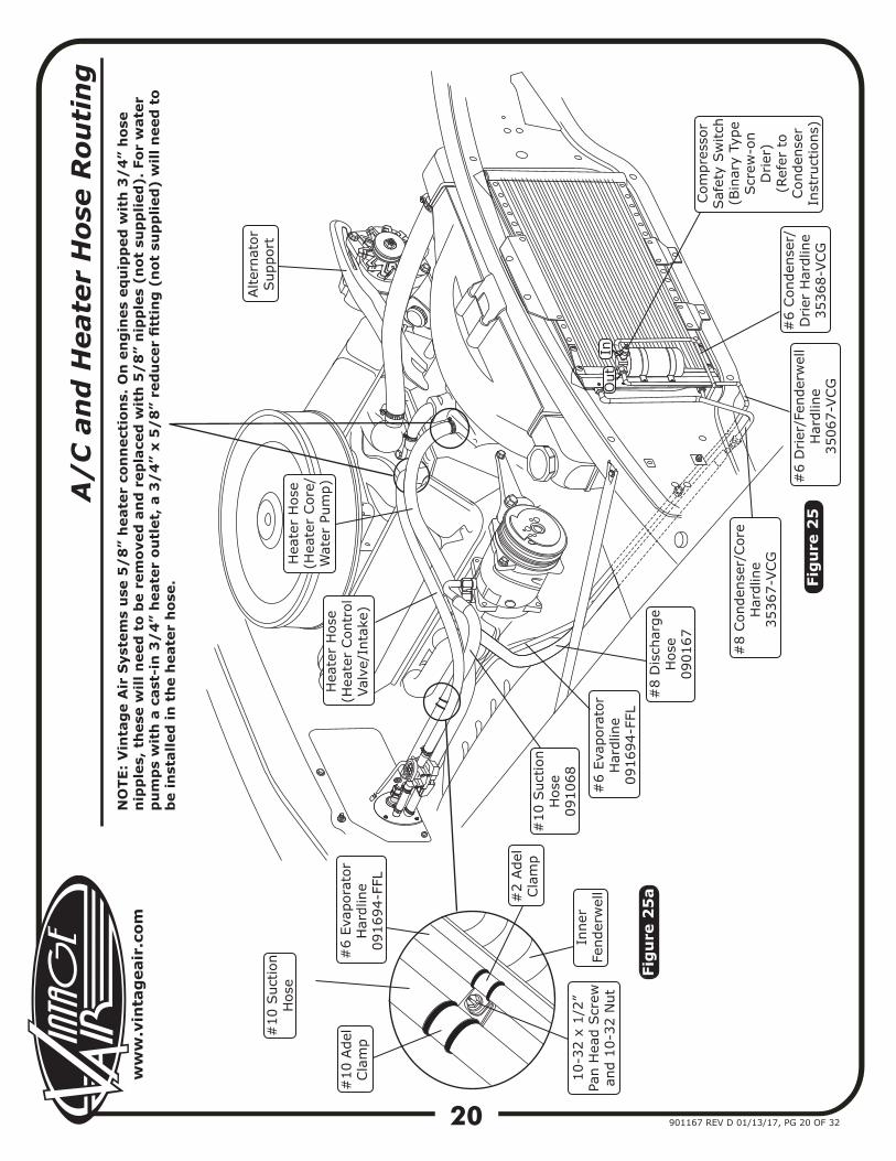
Route a piece of heater hose from the lower heater core fitting to the water pump (See Figure 24, below, & Figure 25, Page 20). Secure using hose clamps.Route a piece of heater hose from the intake to the heater control valve, and from the heater control valve to the upper heater core fitting (See Figure 24, below, & Figure 25, Page 20). NOTE: Install the heater control valve in line with the intake manifold (pressure side) heater hose, and secure using hose clamps. Also note proper flow direction. Use #2 and #10 Adel clamps to secure the #6 evaporator/core support hardline and the #10 suction hose to the inner fender as shown in Figure 25, Page 20. Secure the Adel clamps to the inner fender using a 10-32 x 1/2” pan head screw and a 10-32 nut (See Figure 25a, Page 20).
Figure 24
PressTape#10 Hardline
(Insulated)09151-PCS
ExpansionValve
#6 Hardline09150-PCL
Heater Line(Intake)
09152-PCH
Heater Line(Water Pump)09153-PCH
Firewall Cap
Heater ControlValve
#10 O-ring
#6 O-ring
HeaterHoses
NOTE: Flow Direction Follows Molded Arrow on Valve.
#10 Suction Hose
From Heater Control Valve to Evaporator
From Evaporator to Water Pump#6 Hardline
091694-FFL
From Intake Manifold
ww
w.v
inta
gea
ir.c
om
20 901167 REV D 01/13/17, PG 20 OF 32
A/
C a
nd
Hea
ter
Hos
e R
outi
ng
NO
TE:
Vin
tag
e A
ir S
yste
ms
use
5/
8”
hea
ter
con
nec
tion
s. O
n e
ng
ines
eq
uip
ped
wit
h 3
/4
” h
ose
nip
ple
s, t
hes
e w
ill n
eed
to
be
rem
oved
an
d r
epla
ced
wit
h 5
/8
” n
ipp
les
(not
su
pp
lied
). F
or w
ater
p
um
ps
wit
h a
cas
t-in
3/
4”
hea
ter
outl
et,
a 3
/4
” x
5/
8”
red
uce
r fi
ttin
g (
not
su
pp
lied
) w
ill n
eed
to
be
inst
alle
d in
th
e h
eate
r h
ose.
#10
Ade
l Cla
mp
#10
Suc
tion
Hos
e09
1068
#8
Dis
char
ge
Hos
e09
0167
#2
Ade
lCla
mp
Inne
rFe
nder
wel
l10
-32
x 1/
2”Pa
n H
ead
Scr
ewan
d 10
-32
Nut
#6
Evap
orat
orH
ardl
ine
0916
94-F
FL
#6
Evap
orat
orH
ardl
ine
0916
94-F
FL
Hea
ter
Hos
e(H
eate
r Con
trol
Valv
e/In
take
)
#10
Suc
tion
Hos
eH
eate
r H
ose
(Hea
ter
Cor
e/W
ater
Pum
p)
Alte
rnat
orSup
port
#8
Con
dens
er/C
ore
Har
dlin
e35
367-
VCG
#6
Drier
/Fen
derw
ell
Har
dlin
e35
067-
VCG
#6
Con
dens
er/
Drier
Har
dlin
e35
368-
VCG
Com
pres
sor
Saf
ety
Switc
h(B
inar
y Ty
peScr
ew-o
n D
rier
)(R
efer
to
Con
dens
er
Inst
ruct
ions
)Fi
gu
re 2
5
Fig
ure
25
a
InO
ut
21
www.vintageair.com
901167 REV D 01/13/17, PG 21 OF 32
Figure 27
Figure 26
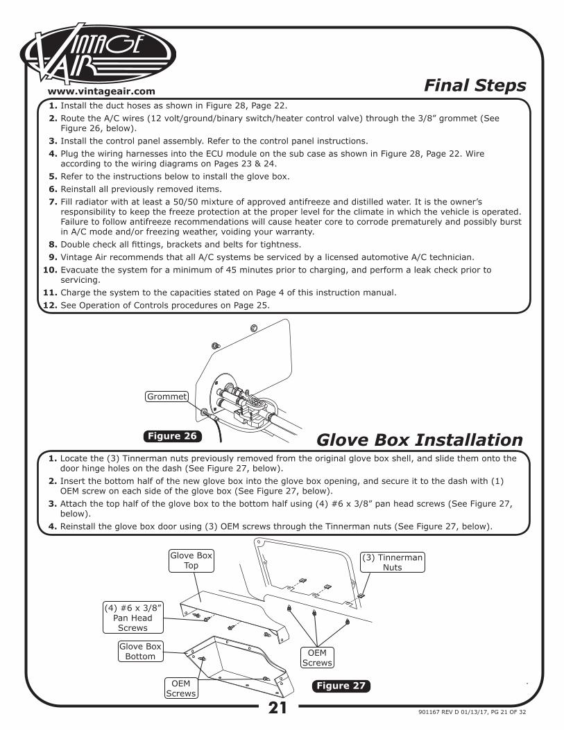
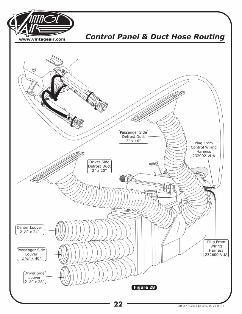
Final Steps1.2.
3.4.
5.6.7.
8.9.
10.
11.12.
Install the duct hoses as shown in Figure 28, Page 22.Route the A/C wires (12 volt/ground/binary switch/heater control valve) through the 3/8” grommet (See Figure 26, below).Install the control panel assembly. Refer to the control panel instructions.Plug the wiring harnesses into the ECU module on the sub case as shown in Figure 28, Page 22. Wire according to the wiring diagrams on Pages 23 & 24.Refer to the instructions below to install the glove box.Reinstall all previously removed items.Fill radiator with at least a 50/50 mixture of approved antifreeze and distilled water. It is the owner’sresponsibility to keep the freeze protection at the proper level for the climate in which the vehicle is operated. Failure to follow antifreeze recommendations will cause heater core to corrode prematurely and possibly burst in A/C mode and/or freezing weather, voiding your warranty.Double check all fittings, brackets and belts for tightness.Vintage Air recommends that all A/C systems be serviced by a licensed automotive A/C technician.Evacuate the system for a minimum of 45 minutes prior to charging, and perform a leak check prior to servicing.Charge the system to the capacities stated on Page 4 of this instruction manual.See Operation of Controls procedures on Page 25.
Glove Box Installation1.
2.
3.
4.
Locate the (3) Tinnerman nuts previously removed from the original glove box shell, and slide them onto the door hinge holes on the dash (See Figure 27, below).Insert the bottom half of the new glove box into the glove box opening, and secure it to the dash with (1) OEM screw on each side of the glove box (See Figure 27, below).Attach the top half of the glove box to the bottom half using (4) #6 x 3/8” pan head screws (See Figure 27, below).Reinstall the glove box door using (3) OEM screws through the Tinnerman nuts (See Figure 27, below).
Glove BoxTop
Glove BoxBottom
OEMScrews
OEMScrews
(3) TinnermanNuts
Grommet
(4) #6 x 3/8”Pan Head Screws
22
www.vintageair.com
901167 REV D 01/13/17, PG 22 OF 32
Figure 28
Control Panel & Duct Hose Routing
Driver SideDefrost Duct
2” x 20”
Passenger SideDefrost Duct
2” x 16”
Center Louver2 ½” x 24”
Passenger SideLouver
2 ½” x 40”
Driver Side Louver
2 ½” x 28”
Plug FromWiring
Harness232600-VUA
Plug FromControl Wiring
Harness232002-VUA
23
www.vintageair.com
901167 REV D 01/13/17, PG 23 OF 32
WHT/GRN
WHT/YELWHT/RED
RED
WHTBACKLIGHT NEG
FAN WIPER
MODE WIPER
TEMP WIPER
5V-SW
GND
BACKLIGHT POS
AC ANNUNCIATOR
PRE-WIRED
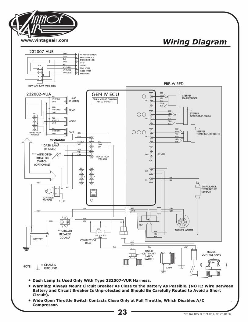
GEN IV WIRING DIAGRAMREV D, 5/6/2014
GEN IV ECU
PROGRAM
Wiring Diagram
TEMP
MODE
FAN
A/C(IF USED)
232007-VUR
232002-VUA
** CIRCUITBREAKER30 AMP
*** WIDE OPENTHROTTLESWITCH
(OPTIONAL)
* DASH LAMP(IF USED)
Dash Lamp Is Used Only With Type 232007-VUR Harness.Warning: Always Mount Circuit Breaker As Close to the Battery As Possible. (NOTE: Wire BetweenBattery and Circuit Breaker Is Unprotected and Should Be Carefully Routed to Avoid a ShortCircuit).Wide Open Throttle Switch Contacts Close Only at Full Throttle, Which Disables A/C Compressor.
JF8
BLK
ORA
TAN
VIEWED FROM WIRE SIDE
••
•
HEATERCONTROL VALVE
24
www.vintageair.com
901167 REV D 01/13/17, PG 24 OF 32
RED
CIRCUIT BREAKER30 AMP
+
+
-
BLACK
REDWHITE
RED
CHASSIS GROUND
A/CCOMPRESSOR
RELAY
Ignition Switch:
Dash Light:
NOTE: MOUNT RELAYIN DESIRED LOCATION
UNDER DASH
GREEN
FIREWALL
BLUE
BLUE
RED &
WHITE
VIOLET
(IGNITION HOTTERMINAL)
IGNITION SWITCH
DASH BACK LIGHT+0-12vTAN
GRAY
BLUE
WHITE
WHITE
REDRED
WHITE
COMPRESSOR
BATTERY
NOTE: CONNECT WHITEWIRES DIRECTLY TO
(-) BATTERY TERMINAL
BATRUN
12V
RED GREEN
RED
RED
BLUE
LATCH
BLACK
BINARYSAFETYSWITCH
YELLOW
ORANGE
WIRING HARNESS
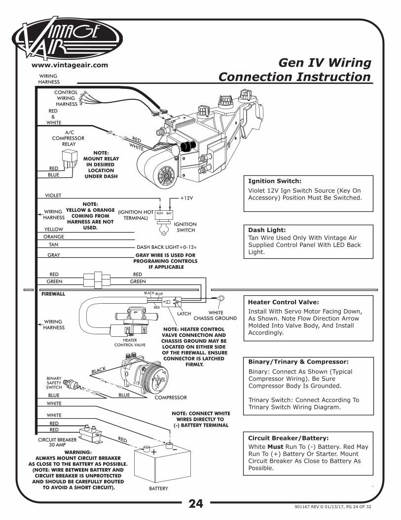
Violet 12V Ign Switch Source (Key On Accessory) Position Must Be Switched.
Tan Wire Used Only With Vintage Air Supplied Control Panel With LED Back Light.
Binary: Connect As Shown (Typical Compressor Wiring). Be Sure Compressor Body Is Grounded.
Trinary Switch: Connect According To Trinary Switch Wiring Diagram.
Install With Servo Motor Facing Down, As Shown. Note Flow Direction Arrow Molded Into Valve Body, And Install Accordingly.
White Must Run To (-) Battery. Red May Run To (+) Battery Or Starter. Mount Circuit Breaker As Close to Battery As Possible.
Heater Control Valve:
Binary/Trinary & Compressor:
Circuit Breaker/Battery:
CONTROL WIRING HARNESS
NOTE: YELLOW & ORANGE
COMING FROM HARNESS ARE NOT
USED.
WIRING HARNESS
GRAY WIRE IS USED FOR PROGRAMING CONTROLS
IF APPLICABLE
WIRING HARNESS
Gen IV Wiring Connection Instruction
HEATERCONTROL VALVE
WARNING: ALWAYS MOUNT CIRCUIT BREAKER
AS CLOSE TO THE BATTERY AS POSSIBLE. (NOTE: WIRE BETWEEN BATTERY AND CIRCUIT BREAKER IS UNPROTECTED
AND SHOULD BE CAREFULLY ROUTED TO AVOID A SHORT CIRCUIT).
NOTE: HEATER CONTROL VALVE CONNECTION AND CHASSIS GROUND MAY BE LOCATED ON EITHER SIDE OF THE FIREWALL. ENSURECONNECTOR IS LATCHED
FIRMLY.

25
www.vintageair.com
901167 REV D 01/13/17, PG 25 OF 32
Operation of Controls
Adjust to desiredspeed.
Blower SpeedAdjust to desired
speed.
Adjust to desiredmode position (DASH position recommended).
Adjust to desiredspeed.
Adjust to DEFROST position for maximum defrost, or between FLOOR and DEFROST positions for a bi-level
blend (Compressor is automatically engaged).
Adjust to desired temperature.
For A/C operation, adjust tocoldest position to engage
compressor (Adjust between HOT and COLD to reachdesired temperature).
A/C Operation
Heat Operation
Defrost/De-fog Operation
On Gen IV systems with three lever/knob controls, the temperature control toggles between heat and A/C operations. To activate A/C, move the temperature lever/knob all the way to cold and then back it off to the desired vent temperature. For heat operation, move the temperature lever/knob all the way to hot and then adjust to the desired vent temperature. The blower will momentarily change speed, each time you toggle between operations, to indicate the change. NOTE: For proper control panel function, refer to control panel instructions for calibration procedure.
Blower Speed
Blower Speed
This lever/knob controlsblower speed, from
OFF to HI.
This lever/knob controls the mode positions,from DASH to FLOORto DEFROST, with a blend in between.
This lever/knob controlsthe temperature,
from HOT to COLD.
Blower Speed
Mode Control
Temperature Control
Temperature Control
Temperature Control
Temperature Control
Mode Control
Mode Control
Mode Control
For maximum heating, adjust to hottest position (Adjust between HOT and COLD to reach desired temperature).Adjust to desired
mode position(FLOOR position recommended).
DASH
DASH
DASH
HOT
HOT
HOT
HI
HI
HI
DASH
HOT
HI
Blower Speed
TemperatureControl
ModeControl
ww
w.v
inta
gea
ir.c
om
26 901167 REV D 01/13/17, PG 26 OF 32
Sym
pto
m
C
on
dit
ion
C
heck
s
Act
ion
s
N
ote
s
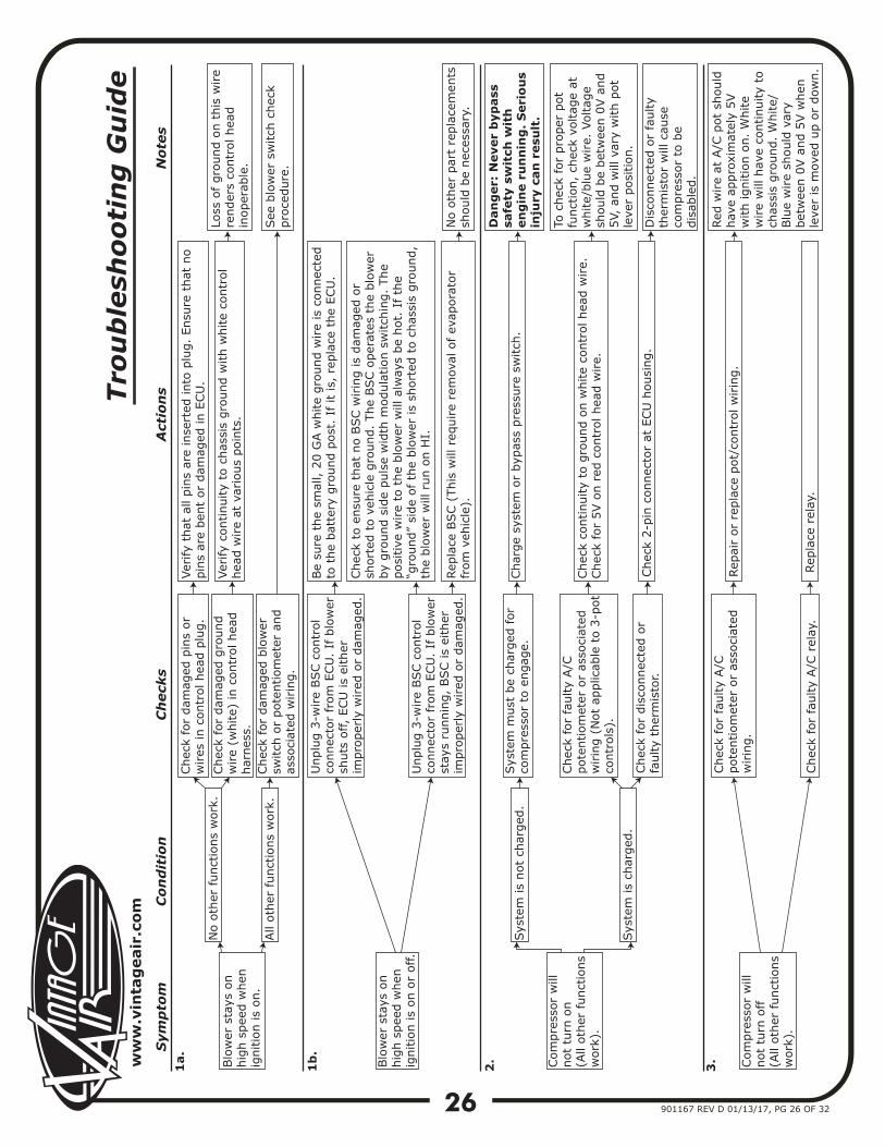
Blo
wer
sta
ys o
n
hig
h s
pee
d w
hen
ig
nitio
n is
on.
1a.
No o
ther
funct
ions
work
.
Chec
k fo
r dam
aged
pin
s or
wires
in c
ontr
ol hea
d p
lug.
Ver
ify
that
all
pin
s ar
e in
sert
ed into
plu
g.
Ensu
re t
hat
no
pin
s ar
e ben
t or
dam
aged
in E
CU
.
Chec
k fo
r dam
aged
gro
und
wire
(white)
in c
ontr
ol hea
d
har
nes
s.
Ver
ify
continuity
to c
has
sis
gro
und w
ith w
hite
contr
ol
hea
d w
ire
at v
ario
us
poin
ts.
Loss
of gro
und o
n t
his
wire
render
s co
ntr
ol hea
d
inoper
able
.
All
oth
er f
unct
ions
work
.Chec
k fo
r dam
aged
blo
wer
sw
itch
or
pote
ntiom
eter
and
asso
ciat
ed w
irin
g.
Blo
wer
sta
ys o
n
hig
h s
pee
d w
hen
ig
nitio
n is
on o
r off.
Unplu
g 3
-wire
BSC c
ontr
ol
connec
tor
from
ECU
. If
blo
wer
sh
uts
off,
ECU
is
eith
er
impro
per
ly w
ired
or
dam
aged
.
Be
sure
the
smal
l, 2
0 G
A w
hite
gro
und w
ire
is c
onnec
ted
to t
he
bat
tery
gro
und p
ost
. If
it
is,
repla
ce t
he
ECU
.
Unplu
g 3
-wire
BSC c
ontr
ol
connec
tor
from
ECU
. If
blo
wer
st
ays
runnin
g,
BSC is
eith
er
impro
per
ly w
ired
or
dam
aged
.
Chec
k to
ensu
re t
hat
no B
SC w
irin
g is
dam
aged
or
short
ed t
o v
ehic
le g
round.
The
BSC o
per
ates
the
blo
wer
by
gro
und s
ide
puls
e w
idth
modula
tion s
witch
ing.
The
posi
tive
wire
to t
he
blo
wer
will
alw
ays
be
hot.
If th
e “g
round”
side
of
the
blo
wer
is
short
ed t
o c
has
sis
gro
und,
the
blo
wer
will
run o
n H
I.
Rep
lace
BSC (
This
will
req
uire
rem
oval
of
evap
ora
tor
from
veh
icle
).N
o o
ther
par
t re
pla
cem
ents
sh
ould
be
nec
essa
ry.
Com
pre
ssor
will
not
turn
on
(All
oth
er funct
ions
work
).
2.
Sys
tem
is
not
char
ged
.Sys
tem
must
be
char
ged
for
com
pre
ssor
to e
ngag
e.Char
ge
syst
em o
r byp
ass
pre
ssure
sw
itch
.
Dan
ger:
Never
byp
ass
sa
fety
sw
itch
wit
h
en
gin
e r
un
nin
g.
Seri
ou
s in
jury
can
resu
lt.
Sys
tem
is
char
ged
.
1b
.
Tro
ub
lesh
oo
tin
g G
uid
e
Chec
k fo
r fa
ulty
A/C
pote
ntiom
eter
or
asso
ciat
ed
wirin
g (
Not
applic
able
to 3
-pot
contr
ols
).
Chec
k fo
r dis
connec
ted o
r fa
ulty
ther
mis
tor.
Chec
k co
ntinuity
to g
round o
n w
hite
contr
ol hea
d w
ire.
Chec
k fo
r 5V o
n r
ed c
ontr
ol hea
d w
ire.
Chec
k 2-p
in c
onnec
tor
at E
CU
housi
ng.
To c
hec
k fo
r pro
per
pot
funct
ion,
chec
k vo
ltag
e at
w
hite/
blu
e w
ire.
Voltag
e sh
ould
be
bet
wee
n 0
V a
nd
5V,
and w
ill v
ary
with p
ot
leve
r posi
tion.
Dis
connec
ted o
r fa
ulty
ther
mis
tor
will
cau
se
com
pre
ssor
to b
e dis
able
d.
Red
wire
at A
/C p
ot
should
hav
e ap
pro
xim
atel
y 5V
with ignitio
n o
n.
White
wire
will
hav
e co
ntinuity
to
chas
sis
gro
und.
White/
Blu
e w
ire
should
var
y bet
wee
n 0
V a
nd 5
V w
hen
le
ver
is m
oved
up o
r dow
n.
3. Com
pre
ssor
will
not
turn
off
(A
ll oth
er funct
ions
work
).
Chec
k fo
r fa
ulty
A/C
pote
ntiom
eter
or
asso
ciat
ed
wirin
g.
Chec
k fo
r fa
ulty
A/C
rel
ay.
Rep
air
or
repla
ce p
ot/
contr
ol w
irin
g.
Rep
lace
rel
ay.
See
blo
wer
sw
itch
chec
k pro
cedure
.
ww
w.v
inta
gea
ir.c
om
27 901167 REV D 01/13/17, PG 27 OF 32
Sym
pto
m
C
on
dit
ion
Ch
eck
s
Act
ion
s
N
ote
s
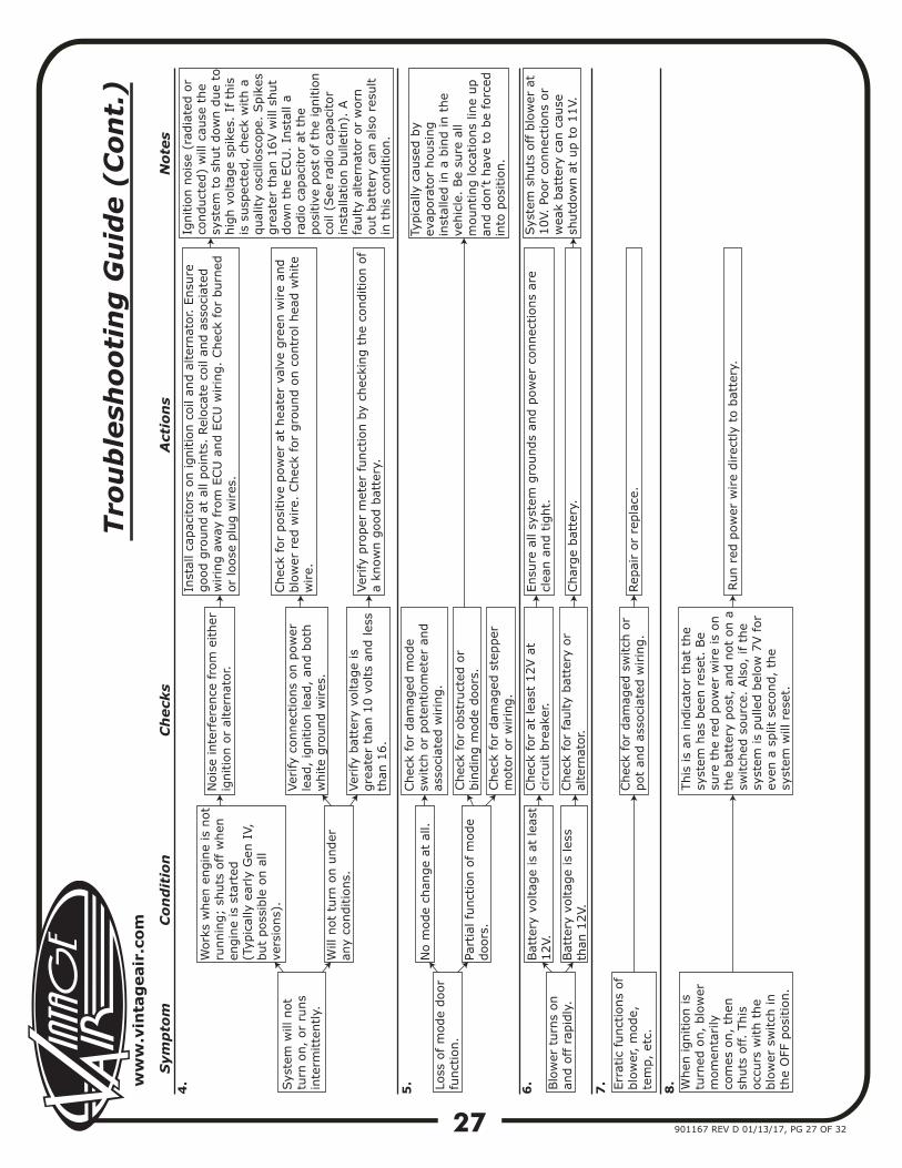
Sys
tem
will
not
turn
on,
or
runs
inte
rmitte
ntly.
4.
Work
s w
hen
engin
e is
not
runnin
g;
shuts
off w
hen
en
gin
e is
sta
rted
(T
ypic
ally
ear
ly G
en I
V,
but
poss
ible
on a
ll ve
rsio
ns)
.
Nois
e in
terf
eren
ce f
rom
either
ig
nitio
n o
r al
tern
ator.
Inst
all ca
pac
itors
on ignitio
n c
oil
and a
lter
nat
or. E
nsu
re
good g
round a
t al
l poin
ts.
Rel
oca
te c
oil
and a
ssoci
ated
w
irin
g a
way
fro
m E
CU
and E
CU
wirin
g.
Chec
k fo
r burn
edor
loose
plu
g w
ires
.
Ver
ify
connec
tions
on p
ow
er
lead
, ig
nitio
n lea
d,
and b
oth
white
gro
und w
ires
.
Ver
ify
pro
per
met
er f
unct
ion b
y ch
ecki
ng t
he
conditio
n o
f a
know
n g
ood b
atte
ry.
Ignitio
n n
ois
e (r
adia
ted o
rco
nduct
ed)
will
cau
se t
he
syst
em t
o s
hut
dow
n d
ue
tohig
h v
oltag
e sp
ikes
. If
this
is s
usp
ecte
d,
chec
k w
ith a
qual
ity
osc
illosc
ope.
Spik
esgre
ater
than
16V w
ill s
hut
dow
n t
he
ECU
. In
stal
l a
radio
cap
acitor
at t
he
posi
tive
post
of th
e ig
nitio
nco
il (S
ee r
adio
cap
acitor
inst
alla
tion b
ulle
tin).
A
faulty
alte
rnat
or
or
worn
out
bat
tery
can
als
o r
esult
in t
his
conditio
n.
Will
not
turn
on u
nder
an
y co
nditio
ns.
Ver
ify
bat
tery
voltag
e is
gre
ater
than
10 v
olts
and les
sth
an 1
6.
Loss
of m
ode
door
funct
ion.
No m
ode
chan
ge
at a
ll.Chec
k fo
r dam
aged
mode
switch
or
pote
ntiom
eter
and
asso
ciat
ed w
irin
g.
Part
ial fu
nct
ion o
f m
ode
doors
.
Typic
ally
cau
sed b
y ev
apora
tor
housi
ng
inst
alle
d in a
bin
d in t
he
vehic
le.
Be
sure
all
mounting loca
tions
line
up
and d
on’t h
ave
to b
e fo
rced
in
to p
osi
tion.
Blo
wer
turn
s on
and o
ff r
apid
ly.
6.
Bat
tery
voltag
e is
at
leas
t 12V.
Chec
k fo
r at
lea
st 1
2V a
t ci
rcuit b
reak
er.
Ensu
re a
ll sy
stem
gro
unds
and p
ow
er c
onnec
tions
are
clea
n a
nd t
ight.
Bat
tery
voltag
e is
les
s th
an 1
2V.
5.
Tro
ub
lesh
oo
tin
g G
uid
e (
Co
nt.
)
Chec
k fo
r fa
ulty
bat
tery
or
alte
rnat
or.
Char
ge
bat
tery
.
Sys
tem
shuts
off b
low
er a
t 10V.
Poor
connec
tions
or
wea
k bat
tery
can
cau
se
shutd
ow
n a
t up t
o 1
1V.
7. When
ignitio
n is
turn
ed o
n,
blo
wer
m
om
enta
rily
co
mes
on,
then
sh
uts
off.
This
occ
urs
with t
he
blo
wer
sw
itch
in
the
OFF
posi
tion.
This
is
an indic
ator
that
the
syst
em h
as b
een r
eset
. Be
sure
the
red p
ow
er w
ire
is o
nth
e bat
tery
post
, an
d n
ot
on a
sw
itch
ed s
ourc
e. A
lso,
if
the
syst
em is
pulle
d b
elow
7V f
or
even
a s
plit
sec
ond,
the
syst
em w
ill r
eset
.
Run r
ed p
ow
er w
ire
direc
tly
to b
atte
ry.
Chec
k fo
r posi
tive
pow
er a
t hea
ter
valv
e gre
en w
ire
and
blo
wer
red
wire.
Chec
k fo
r gro
und o
n c
ontr
ol hea
d w
hite
wire.
Chec
k fo
r obst
ruct
ed o
r bin
din
g m
ode
doors
.
Chec
k fo
r dam
aged
ste
pper
m
oto
r or
wirin
g.
Err
atic
funct
ions
of
blo
wer
, m
ode,
te
mp,
etc.
Chec
k fo
r dam
aged
sw
itch
or
pot
and a
ssoci
ated
wirin
g.
Rep
air
or
repla
ce.
8.

28
www.vintageair.com
901167 REV D 01/13/17, PG 28 OF 32
NO
TE:
Du
e to
pri
nti
ng
var
ian
ces,
mea
sure
th
e lin
e b
elow
bef
ore
usi
ng
th
is t
emp
late
. If
te
mp
late
is s
cale
d p
rop
erly
, th
e lin
e sh
ould
mea
sure
6 in
ches
.
Evaporator Bracket Template
Fold
Dot
ted
Line
Fold
Dot
ted
Line
Cut
Alo
ng
Dot
ted
Line
Cut
Alo
ng
Dot
ted
Line
4 13⁄
16”3
½”
Mar
k &
Drill
3/16
” H
oles

29
www.vintageair.com
901167 REV D 01/13/17, PG 29 OF 32
Center Vent Template (Vintage Air Louver Only)
Mar
k &
Drill
3/16
” H
oles
4-1
1/1
6"
NO
TE:
Du
e to
pri
nti
ng
var
ian
ces,
mea
sure
th
e lin
e b
elow
bef
ore
usi
ng
th
is t
emp
late
. If
te
mp
late
is s
cale
d p
rop
erly
, th
e lin
e sh
ould
mea
sure
6 in
ches
.
1 ⅝”
Center Vent
Center VentCut Out onDotted Line
Cut Out onDotted Line
Cut Out on Dotted Line and Place on Face of Trim Plate.Mark and Cut Hole.
Top
FoamTemplate
Template for Cutting Hole in Trim Plate for Vintage Air Center Louver Installation
Cut Supplied Foam to Match Template. Peel the Protective Backing and stick onto the Back Side
of the Trim Plate.

30
www.vintageair.com
901167 REV D 01/13/17, PG 30 OF 32
Passenger Side Louver Template (1967 Models Only)
NOTE: Due to printing variances, measure the line below before using this template. If template is scaled properly, the line should measure 6 inches.
Glove BoxEdge
Cut
Cut
Fold Under Dash at Dotted Line
Center Punchand Drill 2 ½”Diameter Hole
Passenger Side
Align withExisting
OEM HoleUnder Dash

31
www.vintageair.com
901167 REV D 01/13/17, PG 31 OF 32
Driver Side Louver Template (1967 Models Only)
Center Punchand Drill 2 ½”Diameter Hole
Align withExisting
OEM HoleUnder Dash
NOTE: Due to printing variances, measure the line below before using this template. If template is scaled properly, the line should measure 6 inches.
Cut
Cut
Fold Under Dash at Dotted Line
Align this Edgewith the Dash toInstrument Panel
Parting Line
Driver Side


32
www.vintageair.com
901167 REV D 01/13/17, PG 32 OF 32
FAN
OFF
COLD
OFF
AIR
TEM PERATURE
DEFROST
HOT
ON
DE-ICE
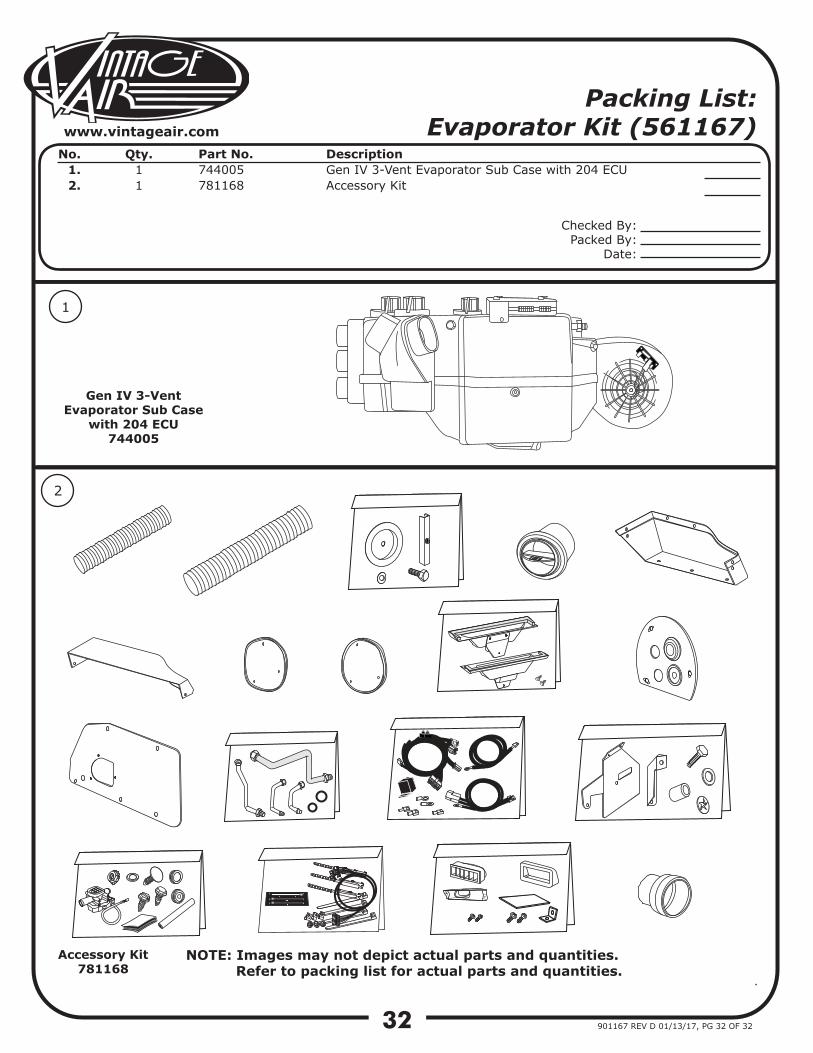
Packing List: Evaporator Kit (561167)
No. 1.2.
Qty.11
Part No.744005781168
DescriptionGen IV 3-Vent Evaporator Sub Case with 204 ECUAccessory Kit
NOTE: Images may not depict actual parts and quantities. Refer to packing list for actual parts and quantities.
1
2
Accessory Kit781168
Checked By:Packed By:
Date:
Gen IV 3-Vent Evaporator Sub Case
with 204 ECU744005