Embed Size (px)
Citation preview

1967-1968
Mustang
Installation Manual

Revised April 28, 2020 Page 2
TableofContentsWELCOME FROM THE TEAM AT CLASSIC INSTRUMENTS! .............................................................................................................. 3
REMOVE THE ORIGINAL INSTRUMENT PANEL .................................................................................................................................... 4
WIRING DIAGRAM .......................................................................................................................................................................................... 6
WIRING THE NEW INSTRUMENT CLUSTER ............................................................................................................................................ 7
OPTIONAL SN16F SPEEDOMETER PULSE GENERATOR WIRING ......................................................................................................................... 8
SPEEDOMETER CALIBRATION ................................................................................................................................................................... 9
ENTERING CALIBRATION MODE: ..................................................................................................................................................................... 10 SPEEDOMETER “INSTANT” CALIBRATION: ....................................................................................................................................................... 10 SPEEDOMETER “REAL-TIME” CALIBRATION: .................................................................................................................................................. 11 SPEEDOMETER “MEASURED MILE” CALIBRATION: ......................................................................................................................................... 12 RESET GAUGE CALIBRATION TO FACTORY DEFAULTS: ................................................................................................................................... 13 VIEW CURRENT SPEEDOMETER CALIBRATION SETTINGS: ............................................................................................................................... 14
TACHOMETER CALIBRATION .................................................................................................................................................................. 15
SET SIGNAL TYPE ............................................................................................................................................................................................ 15 SET # OF CYLINDER SIGNAL TYPE ................................................................................................................................................................... 15 OPTIONAL: SET SHIFT LIGHT TRIGGER POINT ................................................................................................................................................. 15
OIL PRESSURE SENDER INSTALLATION ............................................................................................................................................... 16
TEMPERATURE SENDER INSTALLATION .............................................................................................................................................. 16
MOUNT NEW INSTRUMENT PANEL ......................................................................................................................................................... 17

Revised April 28, 2020 Page 3
Welcome from the Team at Classic Instruments! Our congratulations and appreciation for your purchase of one of the finest quality sets of specialty instruments
ever produced! Your instrument set has been conceived, designed, and manufactured by Classic Instruments, Inc. in the U.S.A. Each instrument has been tested and certified for accuracy and quality before packaging and shipping.
For trouble-free installation and operation follow the instructions exactly as outlined. Your instruments were assembled to precise specifications and although each has a seven (7) year warranty covering defective parts and workmanship – this warranty will not cover instruments or sender units which have been installed incorrectly.
Follow our recommended procedures for installation and proper hookup to maintain the value and appearance of your instrument set during many future years of accurate and dependable service!
LIMITED WARRANTY
Classic Instruments, Inc. (CI) warrants to the original purchaser that any CI product manufactured or supplied by CI will be free from defects in material and workmanship under normal use and service for a period of seven (7) years from date of purchase.
Improper installation, use of sending units other than CI’s or attempted repair or adjustments by other than CI shall void this warranty. Disassembly of any instruments or senders for whatever reason shall specifically void this warranty.
It’s always easy to look to a part for an issue with your set. Before you conclude that a part may be bad, thoroughly check your work. Today’s semiconductors and passive components have reached incredibly high reliability levels, but there is still room for error in our human construction skills. However, on rare occasions a sour part can slip through. Please be aware that testing can usually determine if the part was truly defective or damaged by assembly or usage. Don’t be afraid of telling us that you “blew it”, we’re all human and in most cases, replacement parts are very reasonably priced.
Purchaser requesting a product to be repaired or replaced under warranty must first call CI at 1-800-575-0461 before the return of defective part. Send defective part to 826 Moll Drive, Boyne City, MI 49712, USA. Include a written description of the failure with defective part.
Purchaser agrees and accepts that under no circumstances will a warranty replacement be furnished until CI has first received, inspected, and tested the returned part.
All other warranties expressed or implied are hereby excluded including any implied warranty of merchandise and implied warranty of fitness for a particular purpose. The sole and exclusive remedy for breach of this warranty is limited to the replacement set forth above.
It is expressly agreed that there shall be no further remedy for consequential or other type of damage, including any claim for loss of profit, engine damage or injury.
TECHNICAL ASSISTANCE 1-800-575-0461
OR Visit our website for the latest in gauge design and updates to our installation manual
www.classicinstruments.com

Revised April 28, 2020 Page 4
Remove the Original Instrument Panel
1) Disconnect the battery before beginning the replacement of the new instrument panel. 2) Remove the 5 screws holding the instrument panel to the dash. Three screws are located at
the top of the instrument panel and two screws are located at the bottom of the instrument panel. Save these screws to use when installing the new instrument panel.
3) Remove the nut from the stud located on the passenger side of the instrument panel. Save this nut to use when installing the new instrument panel.
4) Unscrew the speedometer cable from the back of the speedometer. 5) Unplug the wiper switch from the vehicle wire harness. 6) Unplug the two existing instrument panel wire harness connectors from the vehicle wire
harness. 7) Remove the original instrument panel from the dash. 8) Remove the two screws attaching the wiper switch to the original instrument panel and then
remove the wiper switch. Save the screws and wiper switch to use with the new instrument panel.
See Figure A and Figure B on the following page

Revised April 28, 2020 Page 5
Figure A: Example of original instrument cluster removed from dash (5 screws and 1 nut removed)
Figure B: Unplugged wiper switch and original instrument harness
Screws
Nut
Unplug
Remove

Revised April 28, 2020 Page 6
Wiring Diagram
Grey
Grey
Black
Black
Pink
Pink
Dk. Blue
Blue
Pink / White
Lt. Green
Lt. Blue
Dk. Green
Grey
Black
Pink
Tan
Pink
Te
mp
era
ture S
ign
al [D
k. Gree
n - 9]
Oil P
ressu
re Sig
na
l [Dk. B
lue
- 8]
Fu
el Le
vel S
ign
al [T
an - 7]
Left T
urn In
dicator [L
t. Blu
e - 6]
High B
eam
Indicato
r [Lt. G
reen
- 5]
Rig
ht T
urn
Ind
icato
r [Blu
e / W
hite - 4]
+12V
DC
switch
ed
[Pink - 3]
Dash Ligh
ts Pow
er [Grey - 2]
Good C
ha
ssis Gro
un
d [B
lack - 1]
Tach
ome
ter Signa
l [White - 10
]
Bra
ke Ind
icator [Pin
k / Wh
ite - 11]
Sp
ee
d S
ignal [P
urple
- 12]
Optional S
ignal G
roun
d [Black / W
hite - 13
]
Optional S
ign
al P
ow
er [R
ed / W
hite - 14]
No
t Used
[15]
GreyPurpleBlackPinkRed / White
OF
F
ON
Sp
eed
om
eterC
alibration Button
Tachom
eter
Calibration B
utton
Bla
ck
Brow
n / W
hite
Bla
ck
Bro
wn
Brown
GreyWhiteBlackPink
Brown / White
Filte
r Sw
itch
ON
: PC
M o
r SN
16
FS
pe
ed S
ign
alsO
FF
: VS
S or S
N95
Sp
eed
Sig
nals

Revised April 28, 2020 Page 7
Wiring the New Instrument Cluster
1) Always disconnect the positive lead from the vehicle battery before wiring any gauge. 2) Connect the Pink wire of the wire harness to a +12VDC switched power source. 3) Connect the Black wire of the wire harness to a good chassis ground. 4) Connect the Dark Green wire of the wire harness to the supplied Classic Instruments
temperature sender. 5) Connect a speed signal to the Purple wire of the gauge wire harness to one of the following:
a. White signal wire from a pulse signal generator [SN16F] i. Connect the Red / White wire of the gauge harness to the RED wire of the SN16F. ii. Connect the Black / White wire of the gauge harness to the BLACK wire of the SN16F.
[OR] b. One (either) wire of an electronic transmission 2-wire vehicle speed sensor [VSS].
i. Connect the Black / White wire of the gauge harness to the other wire of the VSS. [OR] c. Speedometer Signal wire of the vehicle computer [PCM].
i. Set the filter switch on the back of the speedometer to ON. 6) Connect the White wire of the wire harness to the tachometer signal.
a. STANDARD POINTS & CONDENSER SYSTEM i. Connect to the negative side of the coil (usually marked as “-“).
b. GMC – HEI (High Energy Ignition System) i. Connect to the “TACH” terminal on coil side of distributor cap.
c. MSD (Multiple Spark Discharge System) i. Connect to the TACH signal from the MSD box.
d. VERTEX MAGNETO SYSTEM i. Connect to the “KILL” terminal on the side of a Vertex magneto body. An external adapter
such as an MSD “Pro Mag Tach Converter” #8132 may be required. e. ACCEL IGNITION COILS
i. Connect to the negative side of the coil. CAUTION! Some Accel ignition coils require the tach signal wire to be connected to the “+” terminal on the coil! PLEASE carefully read Accel’s instructions before connecting ignition coil.
f. MALLORY IGNITION i. Connect to the negative terminal side of coil (usually marked as “-“).
g. ECM TACHOMETER SIGNAL i. Connect to the signal from the computer. The tachometer typically needs to be set on 4
cylinder setting. Set the tach signal type to the Low Voltage option for these signals. h. MULTIPLE COIL IGNITION SYSTEMS
i. A tach signal driver, such as the MSD #8913, and a SN74Z converter may be required to get a proper tachometer signal.
i. NOTICE! For all other ignition systems please look at the owner’s manual for that system.
Revised April 28, 2020 Page 8
7) Connect the Tan wire of the wire harness to a stock [75-10 ohm] fuel sender. 8) Connect the Dark Blue wire of the wire harness to the supplied Classic Instruments oil pressure
sender. 9) Connect the Blue / White wire of the wire harness to the right turn indicator power wire of the
vehicle’s turn signal switch. 10) Connect the Light Blue wire of the wire harness to the left turn indicator power wire of the
vehicle’s turn signal switch. 11) Connect the Light Green wire of the wire harness to the high beam indicator power wire of the
vehicle’s light switch. 12) Connect the Grey wire of the wire harness to the dash light power wire from the vehicle’s light
switch. 13) Connect the Pink / White wire of the wire harness to the Brake indicator wire of the vehicle. 14) Connect the loose Brown Speed calibration wire to one wire one of the included black
calibration buttons. (connect the other wire of the calibration button to the loose black wire) 15) Connect the loose Brown / White Tach calibration wire to one wire one of the included black
calibration buttons. (connect the other wire of the calibration button to the loose black wire)
Optional SN16F Speedometer Pulse Generator Wiring
Attach the signal generator to the transmission speedometer gear housing (where the speedometer cable originally connected). A speedometer driven gear (not supplied) needs to be installed on the transmission end of the sender. Do not use excessive force to tighten. These signal generators produce approximately 16,000 pulses per mile (PPM).
BlackRed
White
Red: ---------- Power (to red / white wire of gauge harness) Black: -------- Ground (to black / white wire of gauge harness) White: -------- Signal (to purple wire of gauge harness)

Revised April 28, 2020 Page 9
Speedometer Calibration
Note: Before performing speedometer calibration, insure you have a good speed signal. Take a test drive and make sure the speedometer shows a speed (even though it may not be correct)! If the speedometer doesn’t show a speed, troubleshoot the speed signal before attempting to calibrate the speedometer.
Only one calibration method is necessary to perform to calibrate the speedometer. Pick the method
that works best for you. The “Instant” calibration method requires a GPS reference speed signal (or pace car). You will
need to drive at 30mph. This method is convenient if the speedometer is more than 10mph off at a known 60mph.
The “Real-time” calibration method requires a GPS reference speed signal (or pace car). This method allows you to drive at any known speed and make changes to the speedometer reading as you go. This method is best used if the speedometer calibration is less than 10mph off at a known 60mph.
The “Measured Mile” calibration method requires you to drive a known mile. This is convenient when a GPS is not available to use as a reference and also if the calibration is off more than 10mph at a known 60mph. The speed at which you drive the known mile can be varied, a GPS reference or pace car is not necessary.
Speedometer Calibration Modes
Speedometer Indication Calibration Mode
50 MPH Speedometer “Instant” Calibration
60 MPH Speedometer “Real-time” Calibration
70 MPH Speedometer “Measured Mile” Calibration
80 MPH Factory Defaults Reset Mode
90 MPH Exit Calibration Mode
100 MPH View Current Calibration Settings

Revised April 28, 2020 Page 10
Entering Calibration Mode:
1) Start with power to the gauge OFF. 2) Press and HOLD the function pushbutton. 3) While holding the pushbutton, start engine. 4) After the engine is started, Release the pushbutton. The speedometer pointer will do a full sweep
and the information screen will read “Entered Setup Mode”. The speedometer pointer will then immediately move to indicate 50MPH and the information screen will read “Set Speed Instant”.
Speedometer “Instant” Calibration: (steps 1-4 may be skipped if the gauge is already in calibration mode)
1) Start with power to the gauge OFF. 2) Press and HOLD the function pushbutton. 3) While holding the pushbutton, start engine. 4) Release the pushbutton after the engine is started. The speedometer will do a full sweep and the
information screen will read “Entered Setup Mode”. 5) After a few seconds, the information screen will read “Set Speed Instant” while the speedometer
will indicate 50MPH. If the speedometer is not showing 50MPH and “Set Speed Instant”, continue to tap the button to cycle through the calibration modes until it comes back to this option.
6) Press and hold the function pushbutton until the speedometer changes to 0 MPH and the
information screen reads 7) Drive the vehicle at exactly 30MPH using a GPS or pace car as a reference. The bottom of the
information screen will show “No Sig” if a speed signal is not detected or flash “Sig” if one is detected.
8) Press and hold the pushbutton while traveling 30MPH for approximately 4 seconds until the speedometer moves up to 30MPH. The speedometer will now track your speed and the information screen will read “Saved Instant”. Verify that the speedometer is reading accurately.
9) Tap the pushbutton to get back to the calibration mode options. 10) Tap the pushbutton (as many times as needed) to move through the calibration modes until you get
to the 90MPH (Exit Calibration Mode) option. Press and hold the button for about 6 seconds until the information screen shows your speed or odometer and the speedometer starts indicating your actual speed. The speedometer calibration is now saved.
Revised April 28, 2020 Page 11
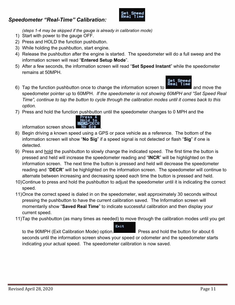
Speedometer “Real-Time” Calibration: (steps 1-4 may be skipped if the gauge is already in calibration mode)
1) Start with power to the gauge OFF. 2) Press and HOLD the function pushbutton. 3) While holding the pushbutton, start engine. 4) Release the pushbutton after the engine is started. The speedometer will do a full sweep and the
information screen will read “Entered Setup Mode”. 5) After a few seconds, the information screen will read “Set Speed Instant” while the speedometer
remains at 50MPH.
6) Tap the function pushbutton once to change the information screen to and move the speedometer pointer up to 60MPH. If the speedometer is not showing 60MPH and “Set Speed Real Time”, continue to tap the button to cycle through the calibration modes until it comes back to this option.
7) Press and hold the function pushbutton until the speedometer changes to 0 MPH and the
information screen shows . 8) Begin driving a known speed using a GPS or pace vehicle as a reference. The bottom of the
information screen will show “No Sig” if a speed signal is not detected or flash “Sig” if one is detected.
9) Press and hold the pushbutton to slowly change the indicated speed. The first time the button is pressed and held will increase the speedometer reading and “INCR” will be highlighted on the information screen. The next time the button is pressed and held will decrease the speedometer reading and “DECR” will be highlighted on the information screen. The speedometer will continue to alternate between increasing and decreasing speed each time the button is pressed and held.
10) Continue to press and hold the pushbutton to adjust the speedometer until it is indicating the correct speed.
11) Once the correct speed is dialed in on the speedometer, wait approximately 30 seconds without pressing the pushbutton to have the current calibration saved. The Information screen will momentarily show “Saved Real Time” to indicate successful calibration and then display your current speed.
11) Tap the pushbutton (as many times as needed) to move through the calibration modes until you get
to the 90MPH (Exit Calibration Mode) option. Press and hold the button for about 6 seconds until the information screen shows your speed or odometer and the speedometer starts indicating your actual speed. The speedometer calibration is now saved.

Revised April 28, 2020 Page 12
Speedometer “Measured Mile” Calibration: (steps 1-4 may be skipped if the gauge is already in calibration mode)
1) Start with power to the gauge OFF. 2) Press and HOLD the function pushbutton. 3) While holding the pushbutton, start engine. 4) Release the pushbutton after the engine is started. The speedometer will do a full sweep and the
information screen will read “Entered Setup Mode”. 5) After a few seconds, the information screen will read “Set Speed Instant” while the speedometer
remains at 50MPH.
6) Tap the function pushbutton twice to change the information screen to and move the speedometer pointer up to 70MPH. If the speedometer is not showing 70MPH and “Set Speed Marked MI”, continue to tap the button to cycle through the calibration modes until it comes back to this option.
7) Press and hold the function pushbutton until the speedometer changes to 30 MPH and the
information screen momentarily shows “Begin Driving” and then changes to . 8) Begin driving a known measured mile. The speed at which you drive the mile does not matter. The
bottom of the information screen will show “No Sig” if a speed signal is not detected or flash “Sig” if one is detected.
9) At the end of the mile, press and hold the pushbutton until the speedometer moves from 30MPH up to 90MPH and the information screen reads “Saved Marked MI”. To get a more accurate calibration, stop at the end of the mile.
10) Press and hold the button (with the speedometer still indicating 90MPH) for about 6 seconds until the information screen shows the speed or odometer and the speedometer starts indicating your actual speed. The speedometer calibration is now saved.
a. If the speedometer is not indicating 90MPH, tap the pushbutton (as many times as needed) to move through the calibration modes until you get to the 90MPH (Exit Calibration Mode)
option. Press and hold the button for about 6 seconds until the information screen shows the odometer and the speedometer starts indicating your actual speed. The speedometer calibration is now saved.
Revised April 28, 2020 Page 13
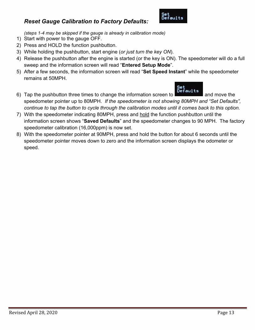
Reset Gauge Calibration to Factory Defaults: (steps 1-4 may be skipped if the gauge is already in calibration mode)
1) Start with power to the gauge OFF. 2) Press and HOLD the function pushbutton. 3) While holding the pushbutton, start engine (or just turn the key ON). 4) Release the pushbutton after the engine is started (or the key is ON). The speedometer will do a full
sweep and the information screen will read “Entered Setup Mode”. 5) After a few seconds, the information screen will read “Set Speed Instant” while the speedometer
remains at 50MPH.
6) Tap the pushbutton three times to change the information screen to and move the speedometer pointer up to 80MPH. If the speedometer is not showing 80MPH and “Set Defaults”, continue to tap the button to cycle through the calibration modes until it comes back to this option.
7) With the speedometer indicating 80MPH, press and hold the function pushbutton until the information screen shows “Saved Defaults” and the speedometer changes to 90 MPH. The factory speedometer calibration (16,000ppm) is now set.
8) With the speedometer pointer at 90MPH, press and hold the button for about 6 seconds until the speedometer pointer moves down to zero and the information screen displays the odometer or speed.

Revised April 28, 2020 Page 14
View Current Speedometer Calibration Settings: (steps 1-4 may be skipped if the gauge is already in calibration mode)
1) Start with power to the gauge OFF. 2) Press and HOLD the function pushbutton. 3) While holding the pushbutton, start engine (or just turn the key ON). 4) Release the pushbutton after the engine is started (or the key is ON). The speedometer will do a full
sweep and the information screen will read “Entered Setup Mode”. 5) After a few seconds, the information screen will read “Set Speed Instant” while the speedometer
remains at 50MPH.
6) Tap the pushbutton five times to change the information screen to and move the speedometer pointer up to 100MPH. If the speedometer is not showing 100MPH and “View Settings”, continue to tap the button to cycle through the calibration modes until it comes back to this option.
7) With the speedometer indicating 100MPH, press and hold the pushbutton until the information
screen shows the pulses per mile (ppm) calibration setting of the speedometer. The speedometer will also move to show your current speed and the bottom of the information screen will show “No Sig” if a speed signal is not detected or flash “Sig” if one is detected.
8) When you are done viewing the calibration settings, tap the pushbutton. The information screen will show “Set Speed Instant” and the pointer will move to 50MPH.
9) Tap the pushbutton (as many times as needed) to move through the calibration modes until you get
to the 90MPH (Exit Calibration Mode) option. Press and hold the button for about 6 seconds until the information screen shows your speed or odometer and the speedometer starts indicating your actual speed.

Revised April 28, 2020 Page 15
Tachometer Calibration
Set Signal Type: 1. Start with power off. 2. Press and hold pushbutton. 3. While pressing pushbutton, apply power to the gauge (starting vehicle not necessary). 4. Release pushbutton once power is applied. 5. Tachometer pointer will indicate 2000 RPM. 6. Press and hold the pushbutton (with tachometer reading 2000 RPM) until the pointer moves
to indicate the signal type. 7. Tapping the pushbutton will cause the pointer to alternate between 5000 RPM “Low Voltage
Signal” (from an ECM) and 6000 RPM “High Voltage Signal” (from standard, HEI or CDI {MSD} ignitions).
8. Press and hold the pushbutton until the pointer returns to 0 RPM to save the setting. Set # of Cylinder Signal Type:
1. Start with power off. 2. Press and hold pushbutton. 3. While pressing pushbutton, apply power to the gauge (starting vehicle not necessary). 4. Release pushbutton once power is applied. 5. Tachometer pointer will indicate 2000 RPM. 6. Tap the pushbutton to index the pointer to 4000 RPM “4-cylinder”, 6000 RPM “6-cylinder” or
8000 RPM “8-cylinder”. 7. Press and hold the pushbutton with the pointer indicating the desired setting (4000, 6000 or
8000) to set the signal type. Once set, the pointer will return to 0 RPM. Optional: Set Shift Light Trigger Point:
1. Start with power off. 2. Press and hold pushbutton. 3. While pressing pushbutton, apply power to the gauge (starting vehicle not necessary). 4. Release pushbutton once power is applied. 5. Tachometer pointer will indicate 2000 RPM. 6. Tap the pushbutton to index the pointer to 3000 RPM. 7. Press and hold the pushbutton (with tachometer reading 3000 RPM) until the pointer moves
to indicate the shift light trigger point. 8. Press and hold the pushbutton to change the RPM shown. The first time the pushbutton is
pressed and held, the RPM shown will increase. The second time the pushbutton is pressed and held, the RPM shown will decrease. The RPM shown will alternate between increasing and decreasing each time the pushbutton is pressed.
9. Once the correct RPM shift light trigger point is shown, wait 8 seconds without pushing the pushbutton in order to save the setting. The pointer will return to 0 RPM.
Important: Turn power OFF to save changes

Revised April 28, 2020 Page 16
Oil Pressure Sender Installation (Part No. SN52)
1) Disconnect battery before installation. 2) Only install Classic Instruments sending units
when the engine is COLD. 3) DO NOT use Teflon tape on the threads. These
threads are slightly tapered and designed to be self-sealing. The sender uses the threads for its ground connection and sealant may cause a poor ground causing inaccurate readings. If supplemental sealant is needed, we recommend using Loctite C5-A anti-seize. This is a copper based anti-seize which will allow a good electrical connection for the sender ground.
4) Connect a wire from the top terminal of the oil pressure sender to the Dark Blue wire of the gauge wire harness.
Temperature Sender Installation (Part No. SN12MM, SN22, SN23, SN24 & SN25)
1) Disconnect battery before making any connections. 2) Install the Classic Instrument’s temperature sending
unit only when the engine is COLD! 3) DO NOT use Teflon tape on the threads. These
threads are slightly tapered and designed to be self-sealing. The sender uses the threads for its ground connection and sealant may cause a poor ground causing inaccurate readings. If supplemental sealant is needed, we recommend using Loctite C5-A anti-seize. This is a copper based anti-seize which will allow a good electrical connection for the sender ground.
4) Install the temperature sender into the intake manifold of your engine if possible. Installing the sender in the engine cylinder head may cause inaccurate temperature readings.
5) Connect a wire from the top terminal of the temperature sender to the Dark Green wire of the gauge wire harness.
6) Tighten until snug. DO NOT OVER TIGHTEN!
Signal Wire
Lock Washer
Nut
Washer
Ring Terminal
Intake Manifold
Nut
Lock Washer
Washer
Signal Wire
Oil Pressure Sender
Ring Terminal
45° Elbow
Entension
Thread Adapter (for Ford applications)
Engine Block
Do Not Remove

Revised April 28, 2020 Page 17
Mount New Instrument Panel
1) Insert wiper switch into new instrument panel. Make sure the non-slotted mounting holes of the switch are toward the bottom of the new instrument panel. Use the original two screws saved from the original instrument panel to fasten the wiper switch to the new instrument panel.
2) Attach the original wiper switch plug to the back of the wiper switch. 3) Mount the new instrument panel to the dash using the 5 mounting screws and nut that were
removed from the original instrument panel.
Stud
Wiper Switch
OFF
ON