Embed Size (px)
Citation preview
1961
VACUUM TUBE EQUALISER
OPERATORS MANUAL
CONTENTS
SAFETY CONSIDERATIONS page 1POWER CONNECTION page 2INSTALLATION page 2FUSES page 3INTRODUCTION page 4APPLICATIONS page 5CONTROL DESCRIPTIONS page 5OPERATION page 7IF A FAULT DEVELOPS page 10CONTACTING DRAWMER page 10TECHNICAL SPECIFICATION page 11BLOCK DIAGRAM page 12
i
COPYRIGHTThis manual is copyrighted © 1995 by Drawmer Electronics, Ltd. With all rightsreserved. Under copyright laws, this manual may not be duplicated in whole or inpart without the written consent of Drawmer.
ONE YEAR LIMITED WARRANTYDrawmer Electronics Ltd., warrants the Drawmer 1961 audio processor toconform substantially to the specifications of this manual for a period of one yearfrom the original date of purchase when used in accordance with thespecifications detailed in this manual. In the case of a valid warranty claim, yoursole and exclusive remedy and Drawmer’s entire liability under any theory ofliability will be to, at Drawmer’s discretion, repair or replace the product withoutcharge, or, if not possible, to refund the purchase price to you. This warranty isnot transferable. It applies only to the original purchaser of the product.
For warranty service please call your local Drawmer dealer. Alternatively callDrawmer Electronics Ltd. at +44 (0)1709 527574. Then ship the defectiveproduct, with transportation and insurance charges pre-paid, to DrawmerElectronics Ltd., Coleman Street, Parkgate, Rotherham, S62 6EL UK. Write theRA number in large letters in a prominent position on the shipping box. Encloseyour name, address, telephone number, copy of the original sales invoice and adetailed description of the problem. Drawmer will not accept responsibility for lossor damage during transit.
This warranty is void if the product has been damaged by misuse, modification orunauthorised repair.
THIS WARRANTY IS IN LIEU OF ALL WARRANTIES, WHETHER ORAL ORWRITTEN, EXPRESSED, IMPLIED OR STATUTORY. DRAWMER MAKES NOOTHER WARRANTY EITHER EXPRESS OR IMPLIED, INCLUDING, WITHOUTLIMITATION, ANY IMPLIED WARRANTIES OF MERCHANTABILITY, FITNESSFOR A PARTICULAR PURPOSE, OR NON-INFRINGEMENT. PURCHASER’SSOLE AND EXCLUSIVE REMEDY UNDER THIS WARRANTY SHALL BE REPAIROR REPLACEMENT AS SPECIFIED HEREIN.
IN NO EVENT WILL DRAWMER ELECTRONICS LTD. BE LIABLE FOR ANYDIRECT, INDIRECT, SPECIAL, INCIDENTAL OR CONSEQUENTIAL DAMAGESRESULTING FROM ANY DEFECT IN THE PRODUCT, INCLUDING LOSTPROFITS, DAMAGE TO PROPERTY, AND, TO THE EXTENT PERMITTED BYLAW, DAMAGE FOR PERSONAL INJURY, EVEN IF DRAWMER HAS BEENADVISED OF THE POSSIBILITY OF SUCH DAMAGES.
Some states and specific countries do not allow the exclusion of impliedwarranties or limitations on how long an implied warranty may last, so the abovelimitations may not apply to you. This warranty gives you specific legal rights. Youmay have additional rights that vary from state to state, and country to country.
In the interests of product development, Drawmer reserve the right to modify orimprove specifications of this product at any time, without prior notice.
ii
1961 OPERATORS’ MANUAL 1
DRAWMER 1961VACUUM TUBE EQUALISER
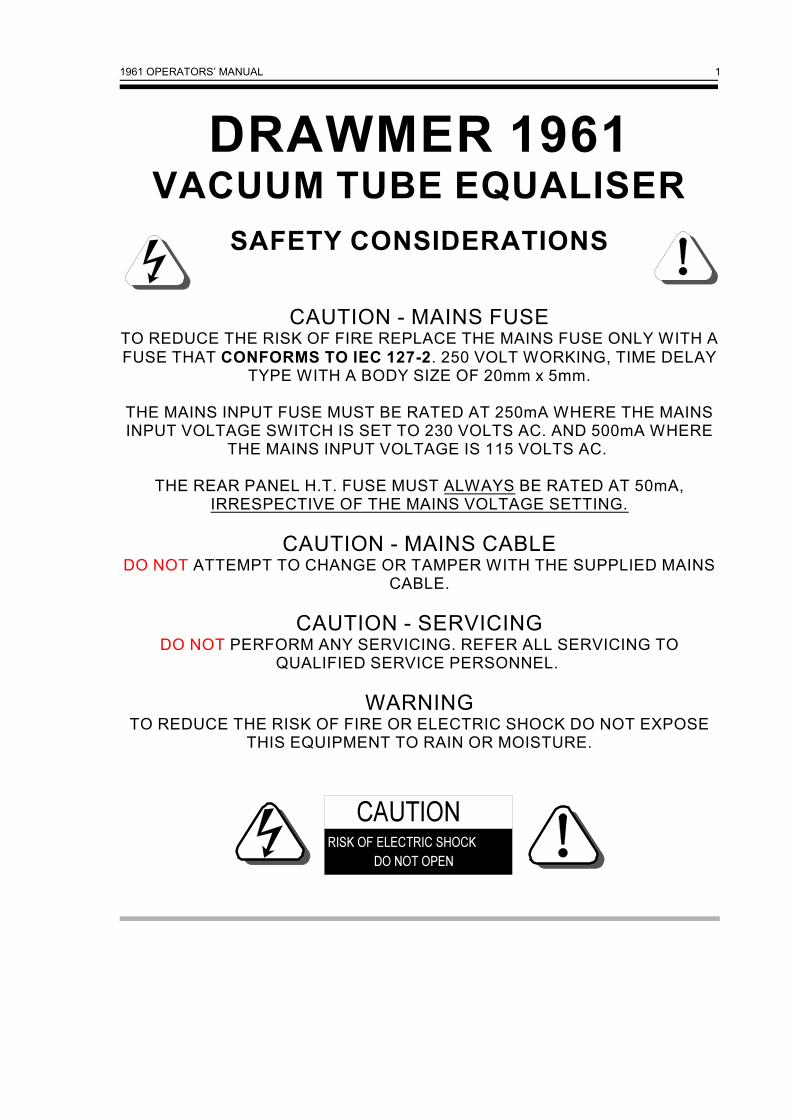
SAFETY CONSIDERATIONS
CAUTION - MAINS FUSETO REDUCE THE RISK OF FIRE REPLACE THE MAINS FUSE ONLY WITH AFUSE THAT CONFORMS TO IEC 127-2. 250 VOLT WORKING, TIME DELAY
TYPE WITH A BODY SIZE OF 20mm x 5mm.
THE MAINS INPUT FUSE MUST BE RATED AT 250mA WHERE THE MAINSINPUT VOLTAGE SWITCH IS SET TO 230 VOLTS AC. AND 500mA WHERE
THE MAINS INPUT VOLTAGE IS 115 VOLTS AC.
THE REAR PANEL H.T. FUSE MUST ALWAYS BE RATED AT 50mA,IRRESPECTIVE OF THE MAINS VOLTAGE SETTING.
CAUTION - MAINS CABLEDO NOT ATTEMPT TO CHANGE OR TAMPER WITH THE SUPPLIED MAINS
CABLE.
CAUTION - SERVICINGDO NOT PERFORM ANY SERVICING. REFER ALL SERVICING TO
QUALIFIED SERVICE PERSONNEL.
WARNINGTO REDUCE THE RISK OF FIRE OR ELECTRIC SHOCK DO NOT EXPOSE
THIS EQUIPMENT TO RAIN OR MOISTURE.

1961 OPERATORS’ MANUAL2
POWER CONNECTION
The unit will have been supplied with a power cable suitable for domestic poweroutlets in your country. For your own safety it is important that you use this cable.The unit should always be connected to the mains supply earth using this cable.
If for some reason the unit is to be used at a mains input operating voltage which isdifferent to that as supplied, the following procedure must be carried out. (Seefollowing diagram)
1: Disconnect the unit from the mains.2: Using a number 1 size pozidrive screwdriver, remove the two self-tappingscrews holding the voltage selection switch cover plate on the rear panel.3: Remove the cover plate and slide the switch fully to its opposite end.4: Rotate the cover plate one half turn, (180E) and refit the two screws.5: Fit a correctly rated fuse for the selected operation voltage.6: Reconnect to mains power source.
INSTALLATION
The 1961 is designed for standard 19" rack mounting and occupies 2U of rack space. Fibre or plastic washers may be used to prevent the front panel becoming marked bythe mounting bolts. Because the tube circuitry generates more heat than anequivalent solid-state design, we recommend space be left above the unit to allowthe heat to dissipate.! Care should be taken in the choice of positioning. The unit should not be
mounted where other equipment obstructs the normal air flow. The unit shouldnot be situated near any heat source, such as a radiator, stove or a highpower amplifier that would generate heat.
! The appliance should not be operated near any water or in a location wheremoisture might be present.
! Always connect the mains earth to the unit.
If the 1961 is to be continuously moved from one location to another, we suggestusing additional support in the rack at the rear of the unit.
1961 OPERATORS’ MANUAL 3
FUSES
The mains fuse should be a class 3, 250 Volt, Time delay type, with a body size of20mm x 5mm, at the correct rating for the mains input voltage. It is very importantthat this fuse complies with IEC127-2. Remember that, in the unlikely event of theunit developing a fault, it is normal for the mains fuse to blow and the unit must beserviced by a qualified service technician.
For added protection the 1961 is also fitted with silicon re-setable fuses. Undercertain conditions, - eg. intermittent mains power, faulty mains cable - these fuseswill 'trip', effectively removing power from the internal circuitry. If this should happen,the silicon fuses will automatically reset after switching off the unit for 15 to 30seconds and then switching back on again. The fuses will probably never trip.Occasionally the fuses might trip repetitively due to an internal fault, in which casethe unit will need attention from a service technician before the silicon fuses willreset.
AUDIO CONNECTIONS
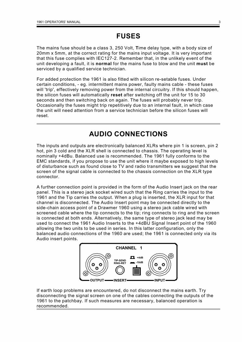
The inputs and outputs are electronically balanced XLRs where pin 1 is screen, pin 2hot, pin 3 cold and the XLR shell is connected to chassis. The operating level isnominally +4dBu. Balanced use is recommended. The 1961 fully conforms to theEMC standards, if you propose to use the unit where it maybe exposed to high levelsof disturbance such as found close to TV and radio transmitters we suggest that thescreen of the signal cable is connected to the chassis connection on the XLR typeconnector.
A further connection point is provided in the form of the Audio Insert jack on the rearpanel. This is a stereo jack socket wired such that the Ring carries the input to the1961 and the Tip carries the output. When a plug is inserted, the XLR input for thatchannel is disconnected. The Audio Insert point may be connected directly to theside-chain access point of a Drawmer 1960 using a stereo jack cable wired withscreened cable where the tip connects to the tip; ring connects to ring and the screenis connected at both ends. Alternatively, the same type of stereo jack lead may beused to connect the 1961 Audio Inserts to the +4dBU Signal Insert point of the 1960allowing the two units to be used in series. In this latter configuration, only thebalanced audio connections of the 1960 are used; the 1961 is connected only via itsAudio insert points.
If earth loop problems are encountered, do not disconnect the mains earth. Trydisconnecting the signal screen on one of the cables connecting the outputs of the1961 to the patchbay. If such measures are necessary, balanced operation isrecommended.
1961 OPERATORS’ MANUAL4
INTRODUCTION
The Drawmer 1961 is a hybrid, vacuum tube/semi-conductor, dual-channel equaliserdesigned to combine the tonal qualities of classic tube circuitry with the low noiseand high reliability associated with contemporary circuit design.
A simple linking facility is included which allows the 1961 to be used in conjunctionwith the Drawmer 1960 tube compressor/preamplifier where it may be used either inthe side-chain ( for de-essing, de-popping and so forth ) or in the main signal path forconventional equalisation.
In addition to tube circuitry being used in each of the four main equaliser bands, afurther tube amplifier is included in the output stage which may be deliberatelyoverdriven to achieve the warm, detailed sound of vintage classic tube designs.
The filters are based around a specialist adaptation of the gyrator 'virtual inductor'circuit which faithfully recreates the essential characteristics of a vintage LC(coil/capacitor) network without incurring the penalties of noise, instability orsusceptibility to magnetic interference. Rather than employ a continuously variableresistor as a means of frequency control, the 1961 utilises the same rotary 'step'switching system used in vintage designs. This enables the component values foreach frequency band to be optimised for uncompromising performance across theentire audio spectrum and also makes setting up more accurate, especially whentreating stereo signals.
The 1961 has numerous applications in studio recording, live sound, locationrecording, post-production and as part of a musician's rack system. It has the benefitof being both simple and intuitive to use and shares the traditional Drawmer stylingadopted for the rest of the product range.
In addition to the four parametric equaliser sections in each channel, the 1961incorporates both high and low pass, 12 dB per octave shelving filters providing theuser with a very precise means of controlling the cutoff frequency at both ends of theaudio spectrum. All filter bands, including the high and low-pass filters, haveindependent Bypass controls and a further Master Bypass switch is provided whichswitches the entire equaliser out of circuit making A/B comparison straightforward.
There are six, dual-stage tubes in the audio signal path with low noise microcircuitsused in the input and output balancing stages as well in certain other noise-criticalareas of the design. The input stages feature extremely low noise, balanced inputcircuitry which may be switched on the rear panel to accept either -10dBV or +4dBUsignals while a five-section, three-colour LED meter monitors the input signal level (whether it is fed from the input XLR or the 1960 Insert linking jack ). An Input gaincontrol provides up to 20dB of further gain and a red peak overload LED warns whenclipping is imminent; a yellow soft-clipping LED shows that the tube circuitry is beingdriven to the level where it is producing musically useful harmonic distortion.
1961 OPERATORS’ MANUAL 5
APPLICATIONS
Further to its obvious applications as a general studio equaliser, the 1961 is alsoparticularly effective as a post-production or mastering tool when used to treatcomplete stereo mixes, especially when used in conjunction with the 1960 tubecompressor. Even before EQ is applied, the output tube circuitry may be mildlyoverdriven in order to add warmth and depth to the sound, while at the same time,emphasising mid-range and high-frequency detail. When used in the side-chain ofthe 1960 or other suitable compressor, the 1961 provides extremely precise controlof de-essing or de-popping.
CONTROL DESCRIPTION
Both channels of the 1961 are identical and may be used independently, or togetherto process a stereo signal. Because the filters use switched frequency controls, it iseasier to set up both channels in an identical manner when processing a stereosignal such as a completed mix. From left to right, the front panel controls are asfollows:
Input Enables the input gain to be varied over the range -20 to +20 dB.A five-segment LED meter shows the input level over the range-10 to +10dB, measured after the input stage but before theequaliser sections. The optimum setting is when the amber LEDis normally illuminated and the +5dB LED lights occasionally.
High-Pass: This is a continually variable 12dB per octave shelving, high-pass filter which may be adjusted over the range 15Hz to 500Hz.
In: This Bypass switch, when pushed in will illuminate the red LED,indicating that the High - Pass is in circuit.
PARAMETRIC FILTERS:
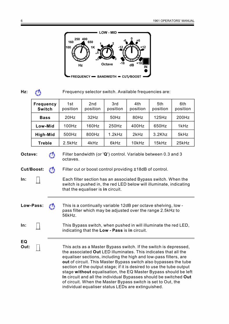
The four filter sections marked Bass, Low-Mid, High-Mid andTreble constitute a fully parametric equaliser, capable ofproviding up to 18dB of cut or boost at the selected frequency asset by the rotary Hz switch. The six switchable frequencies havebeen chosen to correspond to key musical areas in the relevantarea of the musical spectrum. The bandwidth or Q of the filter isdetermined by the Octave control which is continuously variable.This control is calibrated in octaves making it easier to assessits likely effect in a musical context. Each filter section followsthe same basic layout:
1961 OPERATORS’ MANUAL6
Hz: Frequency selector switch. Available frequencies are:
FrequencySwitch
1stposition
2ndposition
3rdposition
4thposition
5thposition
6thposition
Bass 20Hz 32Hz 50Hz 80Hz 125Hz 200Hz
Low-Mid 100Hz 160Hz 250Hz 400Hz 650Hz 1kHz
High-Mid 500Hz 800Hz 1.2kHz 2kHz 3.2Khz 5kHz
Treble 2.5kHz 4kHz 6kHz 10kHz 15kHz 25kHz
Octave: Filter bandwidth (or 'Q') control. Variable between 0.3 and 3octaves.
Cut/Boost: Filter cut or boost control providing ±18dB of control.
In: Each filter section has an associated Bypass switch. When theswitch is pushed in, the red LED below will illuminate, indicatingthat the equaliser is in circuit.
Low-Pass: This is a continually variable 12dB per octave shelving, low -pass filter which may be adjusted over the range 2.5kHz to56kHz.
In: This Bypass switch, when pushed in will illuminate the red LED,indicating that the Low - Pass is in circuit.
EQOut: This acts as a Master Bypass switch. If the switch is depressed,
the associated Out LED illuminates. This indicates that all theequaliser sections, including the high and low-pass filters, areout of circuit. This Master Bypass switch also bypasses the tubesection of the output stage; if it is desired to use the tube outputstage without equalisation, the EQ Master Bypass should be leftIn circuit and all the individual Bypasses should be switched Outof circuit. When the Master Bypass switch is set to Out, theindividual equaliser status LEDs are extinguished.
1961 OPERATORS’ MANUAL 7
O/L (LED): This Overload red LED illuminates when the tube output stageis being driven into audible distortion. This may be used as acreative effect and will not damage the 1961.
Soft (LED): This yellow LED illuminates when the tube output stage is beingdriven into 'soft clipping'. This is the area that produces theclassic tube sound, and though a small amount of harmonicdistortion is being added, the result can often sound cleaner andmore detailed than before treatment. This is due to a psychoacoustic phenomenon whereby the human hearing systemtranslates musically related, high frequency harmonics asadditional high frequency detail and low frequency, second-harmonic distortion as an increase in bass projection. Again, thiseffect can be fine-tuned by ear, using the Input level control toset the precise amount of harmonic distortion.
Power: Power switch. A red status LED beneath the switch shows thatthe unit is powered up.
OPERATION
The unit should be connected in-line with the signal to be processed either directly orvia suitable insert points. The 1961 may also be linked directly to the Side-Chainaccess connector (or to the Audio Insert points) of a Drawmer 1960 tube compressorvia the stereo Audio insert jacks on the 1961 rear panel. This requires only astandard (tip-wired-to-tip and ring-wired-to-ring) screened stereo jack lead.
For mono operation, each channel of the 1961 may be considered as completelyindependent and set up accordingly. For use with stereo signals such as completemixes or submixes, both sets of channel controls should be set to the same positionunless there is a specific reason for not doing so.
Setting up is best approached, initially, by switching In one filter section at a time.Setting the Cut/Boost control to maximum Boost, and then switching through theavailable frequencies is the simplest way of identifying the area of the spectrum thatrequires attention. Once this has been located, the Cut/Boost control may be set toproduce the required amount of Cut or Boost. The Octave control may then beadjusted, by listening to the Input signal and rotating the control to the desiredsetting: An extreme anticlockwise setting produces the narrowest filter characteristicwhich is ideal for 'notching out' troublesome frequencies. However, when theequaliser is being used in Boost mode, a low Octave setting may produce a honky orpeaky sound unless used in moderation. Medium to wide Octave settings, combinedwith modest degrees of Boost, produce the most musical results when it is requiredto emphasize a particular range of frequencies. Narrower Octave settings can beused to emphasize specific instruments such as bass drums or hi-hats, but care mustbe taken not to use so much Boost so as to create an unnatural sound - unless thisis the intention! If large amounts of Boost are applied using one or more equalisersections, there is a possibility that the signal will be amplified to a point where thereis a danger of clipping. If this occurs, monitor the output O/L and Soft LEDs, andadjust the Input gain accordingly.
1961 OPERATORS’ MANUAL8
Note that a small amount of deliberately added tube distortion can produce theflattering effect associated with vintage tube equipment.
The major feature when using the 1961 is that you can control the amount ofenhancement using the Input level control, rather than having to accept what theequipment gives you! Driving the input until the yellow Soft LED comes on generallyproduces the most pleasing result, but this will vary depending on the material beingprocessed and on the taste of the user. If the red O/L LED flashes, the unit is at, orvery near, clipping. It is possible to add subtle amounts of tube distortion by leavingthe master bypass switch set to In and the individual filter bypass switches set to out.This leaves only the output tube in circuit. More dramatic colouration may be addedwhen switching in the individual equalisers; the more EQ Boost applied, the greaterthe degree of tube colouration added by the equaliser stage.
Though the 1961 has a very quiet signal path, applying large amounts of highfrequency Boost will emphasise tape hiss and other background noises, especiallyduring pauses and quiet passages where there is no other sound to mask it. For thisreason, it is unwise to use unnecessary amounts of high end Boost, especially inareas of the spectrum where there is little or no signal to work on. In the case ofinstruments with a limited bandwidth, the noise performance can be improved byusing the Low - Pass filter to 'trim' away the unused top end of the audio spectrum.The filter frequency should be lowered slowly while monitoring its effect on thematerial being processed, so as not to apply filtering and too low a frequency.Examples of where this may be beneficial are when working on miked electric guitarsounds or some of the older electric pianos, both of which produce negligibleamounts of energy above 5kHz. Similarly, the High - Pass filter may be used toremove unwanted bottom end from a sound, for example, the hum from an electricguitar track or the boxiness from a close-miked acoustic guitar.
Hints on Useful Equalisation Frequencies
! Mains hum in the UK and Europe has a fundamental frequency at 50Hzand harmonics at 50Hz intervals stretching up throughout the audiospectrum. By filtering at 50Hz and 100Hz using the narrowest Octavesetting, it is often possible to significantly reduce the perceived level ofhum without unduly affecting the wanted signal. On signals containingno very low frequencies, the High-Pass filter may also be used. Itsfrequency should be set by experimentation so that it is tuned as highas possible without affecting the bass end of the wanted signal.
! Kick Drums: Rock kick drums often benefit from a slight boost at 80Hzwhich produces a tight, punchy sound. However, a deeper sound, moresuited to dance music production, can be achieved by boosting thebass at 32Hz or 50Hz using a medium Octave setting andsimultaneously applying cut at 160Hz to prevent the mid-range frombecoming too boxy (or honky).

1961 OPERATORS’ MANUAL 9
! Electric guitars often need a little EQ to add bite or presence. The HighMid equaliser is ideally suited to this purpose and, depending on theguitar sound sought, the 1.2kHz, 2kHz or 3kHz setting might be mostsuitable. The degree of boost should be set by ear and the startingOctave setting should be 1, though this may also be fine-tuned by ear.Equalisation at the low end of the spectrum (80 - 125Hz) may also bebeneficial in controlling the amount of cabinet resonance added to thesound. The High and Low-Pass filters are also useful in removing humand noise from the sound. Driving the output stage of the 1961 so as togenerate a little audible distortion can also help flatter most electricguitar sounds, especially those generated using a solid-state preamp.
! Acoustic guitars can sound boxy if miked from too close and a little cutat 100Hz or 160Hz can help to even things out. If the sound is too 'flat',try adding a little boost between 5kHz and 8kHz, and to thin out thesound to make it sit nicely in a busy track, try using the High-Pass filterto shave a bit off the bottom end.
! Vocals: different vocalists require different treatment, but it is worthkeeping in mind that the human voice is a familiar sound to all of us,and we soon notice if it has been over-treated. In general, use wideOctave settings and gentle amounts of boost to polish the sound, andby overdriving the tube output stage just slightly, a clinical solid-state ormoving-coil microphone takes on the warm transparency of a tubemicrophone. The amount of overdrive should be set by ear and it isessential to ensure that the amount of added distortion is not overtlynoticeable during loud passages.
Tip: To create the maximum amount of tube distortion without apparently over-equalising the signal, set the four bands to 80Hz, 400Hz, 2kHz and 6kHzrespectively, set all Octave controls fully clockwise and apply around 6dB ofboost on all controls. Adjust the input gain until the yellow Soft LED flashes onsignal peaks. Because a broad filter characteristic has been selected, theoverall signal level will increase and the degree of tube enhancement will bemaximised. This setting works particularly well on bass guitar, and after initialsetting up, the equaliser setting may be fine tuned to create exactly the rightsound.
1961 OPERATORS’ MANUAL10
IF A FAULT DEVELOPS
For warranty service please call Drawmer Electronics Ltd. Or their nearestauthorised service facility, giving full details of the difficulty. On receipt of thisinformation, service or shipping instructions will be forwarded to you. No equipmentshould be returned under the warranty without prior consent from Drawmer or theirauthorised representative.
For service claims under the warranty agreement a service Returns Authorisation(RA) number will be given. Write this RA number in large letters in a prominentposition on the shipping box. Enclose your name, address, telephone number, copyof the original sales invoice and a detailed description of the problem.
Authorised returns should be prepaid and must be insured. All Drawmer products arepackaged in specially designed containers for protection. If the unit is to be returned,the original container must be used. If this container is not available, then theequipment should be packaged in substantial shock-proof material, capable ofwithstanding the handling for the transit.
CONTACTING DRAWMER
Drawmer Electronics Ltd., will be pleased to answer all application questions toenhance your usage of this equipment. Please address correspondence to:
Drawmer (Technical Help line) : Coleman St.: Parkgate : Rotherham : S62 6EL : UK
or, E-mail us on : [email protected]
Drawmer dealers, Authorised service departments and other contact information canbe obtained from our web pages on http://www.drawmer.com

1961 OPERATORS’ MANUAL 11
TECHNICAL SPECIFICATIONS(All measurements taken at +4dBu operating level)
INPUT IMPEDANCES XLR 20KÙINSERT 47KÙ
MAXIMUM INPUT LEVEL +17dB (+21dBu)
OUTPUT IMPEDANCES XLR 50 ÙINSERT 200 Ù
FREQUENCY RESPONSE <22Hz to 42KHz -1dB
CROSSTALK <-80dB @ 10KHz<-75dB @ 20KHz
INPUT CMR Better than 40dB (20Hz to 10KHz)
OUTPUT BALANCE Better than 40dB (20Hz to 10KHz)
NOISE AT UNITY GAIN with flat EQ response switched in circuit
Wideband 22Hz - 22KHz CCIR ARM IEC A Q-Pk CCIR
AV -87dB -94dB -96dB -97dB -85dB
RMS -85dB -92dB -95dB
DISTORTION (THD & Noise) @ 1KHz
XLR Input with BYPASS selected < 0.1%
XLR Input with NORMAL selected < 0.3%
POWER REQUIRED 115 Volt or 230 Volt AC at 50-60Hz 28 Watts
FUSE RATING 250mA for 230 Volt, 500mA for 115 Volt CONFORMING TO IEC 127-2
FUSE TYPE 20mm x 5mm, Class 3, Time delay, 250 Volt working
CASE SIZE 482mm (w) x 88mm (h) x 250mm (d)
WEIGHT 6.1 Kgs
1961 OPERATORS’ MANUAL12
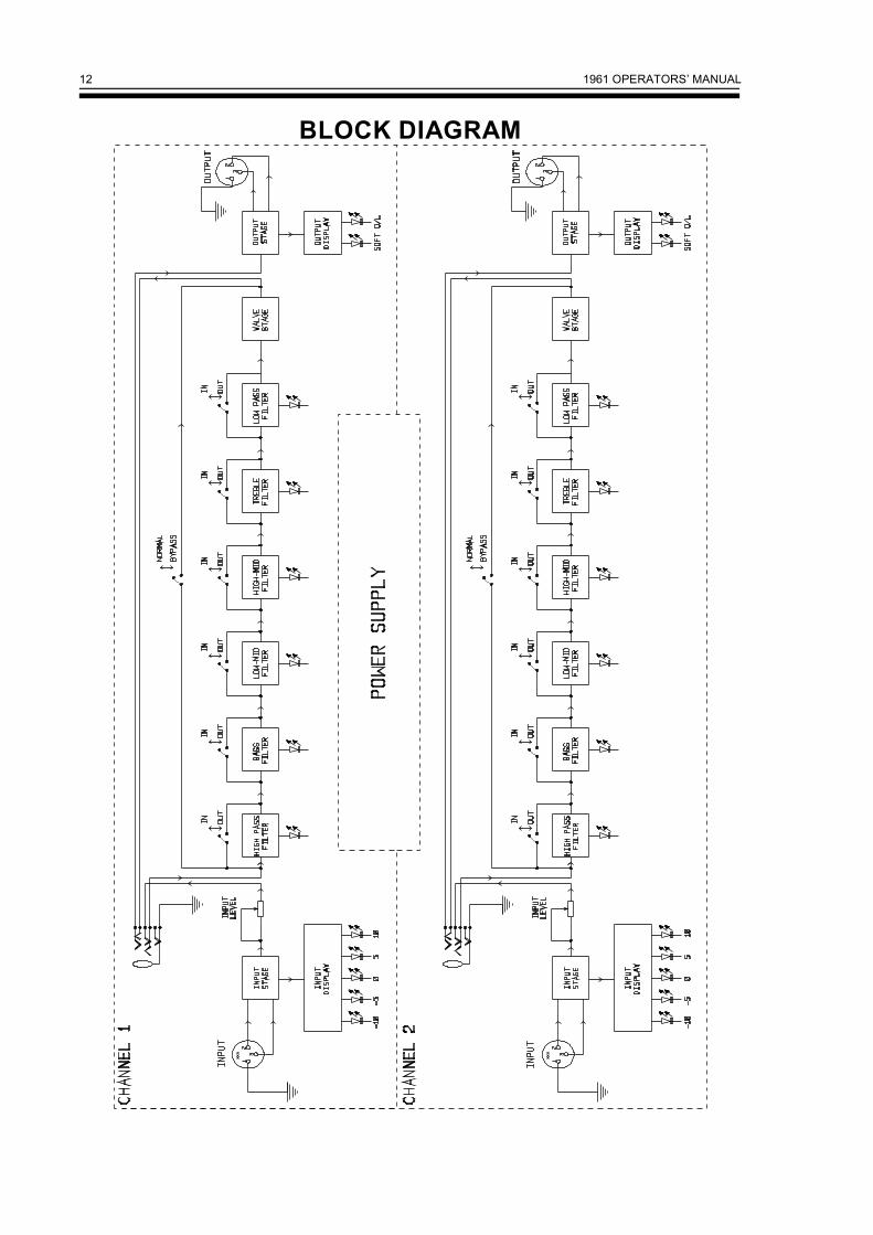
BLOCK DIAGRAM