Embed Size (px)
Citation preview

1 1947-54 Chevrolet IFS Kit 2/1/2013 Rev0
1947-54 Chevrolet 3100 IFS Kit
Congratulations on your purchase on what we believe is the finest IFS kit available for 1947-54
Chevrolet pickups with stock frames. We have invested many hours into designing a kit that
will be effective, easy to install, and offer years of dependable service – and deliver excellent
drivability. To ensure a smooth installation, please read these instructions carefully – don’t
forget to measure twice and cut once. If you have any questions about the installation, please
give us a call.
Main Kit Components
1. Lower assembly: This assembly has the IFS crossmember, frame boxing plates, and
motor mounts welded as one unit. With all these components welded together, engine
placement is pre-configured and the frame is strengthened where it needs to be. The

2 1947-54 Chevrolet IFS Kit 2/1/2013 Rev0
stock core support will locate the front/rear location of this assembly, which ensures the
wheelbase will be within specifications.
2. Upper Control Arm Towers: These assemblies locate the upper control arms and
coilovers. A jig is provided to ensure these are accurately located on the frame.
3. Sway bar mounting plates: These plates will weld to the bottom of the frame rail and
provide threaded holes for the sway bar brackets.
Installation
1. If possible, it is advisable to start with a clean frame that has been degreased and
sandblasted.
2. Remove front shock mounts and both front and rear leaf shackle hangers (front hanger is
an iron casting inside the frame rail). These items are riveted from the factory and can be
removed by grinding the rivet heads or using an air hammer with a chisel attachment. The
rivet shank can then be removed with a punch and hammer.
3. The original front engine mount crossmember may remain in place, however, the lower
webbing that joins the crossmember to the frame rails must be removed so tab A (see
figure 1) on the lower assembly box plates sits flush against the original engine mount
crossmember. Some frames may have a wider lower frame rail flange that must also be
trimmed up to the engine crossmember as shown in figure 2. The width of the lower
flange must match the upper flange, which is about 2-1/4”.
Figure 1 - Box Plate Tabs

3 1947-54 Chevrolet IFS Kit 2/1/2013 Rev0
Figure 2 - Flange Trimming – View from Bottom
4 1947-54 Chevrolet IFS Kit 2/1/2013 Rev0
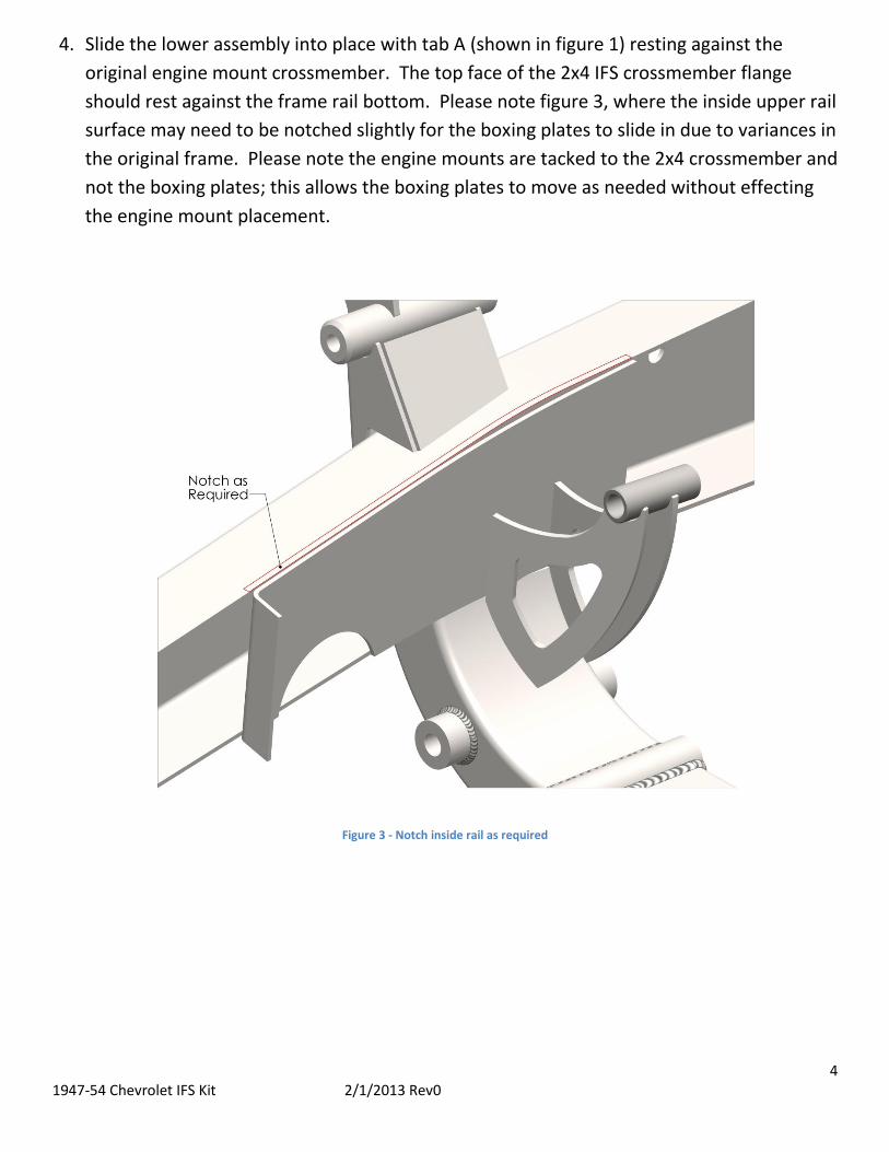
4. Slide the lower assembly into place with tab A (shown in figure 1) resting against the
original engine mount crossmember. The top face of the 2x4 IFS crossmember flange
should rest against the frame rail bottom. Please note figure 3, where the inside upper rail
surface may need to be notched slightly for the boxing plates to slide in due to variances in
the original frame. Please note the engine mounts are tacked to the 2x4 crossmember and
not the boxing plates; this allows the boxing plates to move as needed without effecting
the engine mount placement.
Figure 3 - Notch inside rail as required

5 1947-54 Chevrolet IFS Kit 2/1/2013 Rev0
5. Verify correct front-to-rear location by measuring the distance between the front leaf
hanger hole and front of 2x4 IFS crossmember. The correct location should be
approximately 17-1/4”, plus or minus 1/8”. See figure 4. If the location is correct, tack
weld the boxing plates into place.
Figure 4 - Verifying Correct Location – View from LH Side

6 1947-54 Chevrolet IFS Kit 2/1/2013 Rev0
6. Using the boxing plates as a template, mark the rail where cuts need to be made for
steering rack clearance. Cut the rail with any desired method, and insert supplied half
rounds and tack into place. Keep in mind the circular cutouts must be perpendicular to
the vehicle centerline and not the outside rail face (which is at a 4 degree angle to the
vehicle centerline). Use a straightedge to make sure your layout lines line up with each
other as in figure 5.
Figure 5 - Rack clearance cutouts – View from Bottom

7 1947-54 Chevrolet IFS Kit 2/1/2013 Rev0
7. Bolt the supplied upper tower jig to the IFS crossmember as shown in figure 6, then bolt
the upper towers to the jig.
Figure 6 - Upper Tower Jig Placement - View from LH Side
8. Check the gap between the tower assembly and frame rail. For best weld penetration, it is
advisable to have a small gap between the two components, at least the thickness of MIG
welding wire. Grind the upper tower if necessary. If the fit is satisfactory, begin tack
welding the upper towers to the frame rail.

8 1947-54 Chevrolet IFS Kit 2/1/2013 Rev0
9. Place the threaded sway bar mounting plates in the position shown in figure 7 and mark
the hole centers on the frame rail. Remove the mount plates and drill the frame rail at the
marked locations with a 7/16” or larger drill bit to allow the bolt to pass through the frame
rail when fastening the sway bar bushing bracket. Place the sway bar mount plates back
into position and weld into place.
Figure 7 - Sway Bar Mount Plate Locations – View from Bottom

9 1947-54 Chevrolet IFS Kit 2/1/2013 Rev0
10. The engine mount plates are heavily tacked to the 2x4 crossmember, preventing them
from moving during final welding. However, if there is some concern of the engine mount
bosses not maintaining their 16.5” width, simply use a piece of angle iron drilled at 16.5”
and bolt securely to the mounting bosses. Before final welding, tack the engine mount
plates to the boxing plates.
Figure 8 - Checking Motor Mount Width – View from Front
11. When you are satisfied with the overall fit and finish, you can now fully weld all
components to the frame.
Assembly
1. Using table 1 as a guide, attach the upper and lower control arms with their respective
fasters to the threaded bosses. While both upper control arms are the same, the lowers
are not. Orientate the lower control arm such the 3/8” threaded boss (which attaches
to the sway bar linkage) points forward. Do not tighten the bolts.
2. Attach the spindle to the ball joints. Orientate the spindle such the larger taper boss
connects to the lower ball joint (see figure 10 for a reference picture). Tighten the
castle nuts until snug.
3. Insert the coilover mockup jig into place and temporarily attach with the hardware
listed in table 1. This will keep the spindle at approximately the proper ride height
through the rest of the build process.

10 1947-54 Chevrolet IFS Kit 2/1/2013 Rev0
4. Attach the steering rack to the crossmember, and snug the bolts. Be sure the rack is
centered in its travel, and mark the pinion’s location on the casting so this point can be
referenced later.
5. Thread the outer tie rod onto the inner tie rod shaft, then connect the outer tie rod to
the spindle steering arm and snug the castle nut. Repeat for the opposite side.
6. Roughly align the camber and toe, with the chassis sitting level, using the following
methods:
a. Adjust the camber first by adjusting the tie rod until the spindle is steering
approximately straight. Place a level on a vertical machined surface on the
spindle and adjust the upper control arm rod ends equally until the spindle is
vertical, or 0 degrees camber. Repeat for the opposite side
b. Adjust toe by clamping a straightedge to both spindles as in figure 9. Adjust the
tie rods until measurement A matches measurement B; at this point the spindles
are parallel with each other. Now the thrust angle can be set, which means the
tires will roll in a direction parallel to the vehicle centerline. To do this, take a
straight-line measurement from the tip of the straightedge to a known point that
resides on the vehicle centerline (the middle slots in the core support work well).
As in figure 9, adjust the left and right tie rods equally until measurement C equals
measurement D. When completed, double check that measurement A matches B
and adjust if necessary.
At the point the alignment is close and the vehicle can be driven to a shop for the final
alignment. Refer to table 2 for final alignment specifications.
7. When the vehicle is ready to be driven, remove the coilover mockup jig and bolt in the
coilover assembled with springs, with the valve adjuster facing the outside of the
vehicle. With the vehicle on the ground, adjust the spanner nuts until the coilover
length is approximately 13-1/4”. At this point the control arm bolts may be tightened to
the specifications shown on table 1. After the vehicle has been driven for several miles,
the spanner nuts may need to be re-adjusted as the springs settle and control arm bolts
can be checked for proper torque.

11 1947-54 Chevrolet IFS Kit 2/1/2013 Rev0
Figure 9 – Basic Toe Alignment
Figure 10 - Ride Height Specifications

12 1947-54 Chevrolet IFS Kit 2/1/2013 Rev0
Figure 11 - Ride Height Specifications – Spindle C/L to Frame Bottom
Table 1 - Fastener Torque Specifications
Size Thread Pitch Type Torque LubricationLCA Pivot 5/8 NF CS 79 Anti-seize
UCA Pivot 1/2 NF CS 38 Anti-seize
Upper C/O 1/2 NF CS 35
Lower C/O 1/2 NF SHCS 20 Anti-Seize
Sway Bar
Frame Brackets 3/8 NC CS 20
Lower Link 3/8 NF CS 20
Steering Rack 5/8 NF CS 56
Ball Joint
Upper 9/16 NF Slot Nut 75-90
Lower 9/16 NF Slot Nut 75-90
Tie Rod 1/2 NF Slot Nut 50
Fastener Data
Loca
tion
Table 2 - Alignment Specifications
Suspension Type Toe (Inches) Camber (Deg.) Caster (Deg.)
Deluxe IFS 1/32 to 1/16 (In) 0 to -0.25 +1.5 to +3.0
Alignment Guide

13 1947-54 Chevrolet IFS Kit 2/1/2013 Rev0
Figure 12 - RH Reference Photo