Embed Size (px)
Citation preview
|1| www.kvaser.com
J1939 OVERVIEW
Table of Contents
J1939: Introduction ...............................................................................................................................2
Introduction ...................................................................................................................................................................... 2
Quick facts ....................................................................................................................................................................... 2
The SAE J1939 standards .......................................................................................................................................... 2
J1939: In Depth ......................................................................................................................................4
Message Format and Usage (J1939/21) .............................................................................................................. 4
Addresses and Names (J1939/81) .......................................................................................................................... 5
Address Claim ................................................................................................................................................................. 7
Transmitting Messages (J1939/21 and J1939/7x) .......................................................................................... 8
TP_BAM messages ....................................................................................................................................................... 9
TP_CM messages .......................................................................................................................................................... 9
Receiving Messages (J1939/21 and J1939/7x) ................................................................................................. 9
ECU Design (J1939/1x, J1939/21, and J1939/7x) ............................................................................................ 9
Wiring Topology – Physical Layer (J1939/1x) ..................................................................................................10
Example of how to interpret a J1939 message ..............................................................................................10
Next Steps ............................................................................................................................................12
Get the Complete J1939 Specification Documents .......................................................................................12
Compare J1939 Compatible Software Suites ..................................................................................................12
Order a J1939 Diagnostic Cable ...........................................................................................................................12
APPENDIX A ..........................................................................................................................................13
J1939/11 Physical Layer ...........................................................................................................................................13
J1939/13 Off-Board Diagnostic Connector ......................................................................................................13
J1939/21 Data Link Layer .......................................................................................................................................13
J1939/31 Network Layer ..........................................................................................................................................14
J1939/71 Vehicle Application Layer .....................................................................................................................15
J1939/73 Application Layer – Diagnostics .......................................................................................................15
J1939/81 Network Management ..........................................................................................................................16
|2| www.kvaser.com
J1939 OVERVIEW
J1939: Introduction
IntroductionJ1939 is a set of standards defined by the Society of Automotive Engineers (SAE). J1939 standards are used to design electrical systems on heavy-duty vehicles such as trucks, buses, and mobile hydraulics.
The J1939 specification provides direction for the physical layer, diagnostic connector, and several layers of messaging architecture. In many ways, J1939 is similar to the older J1708 and J1587 standards, but J1939 is built on CAN (Controller Area Network, ISO 11898).
Perhaps most importantly for the heavy duty vehicle industry, J1939 prescribes a standard set of message parameter groups - referred to as PGN’s - for communication on the electrical bus. A set of ‘custom’ message parameters are also reserved for proprietary third party usage. This provides two benefits at once: 1) a standardized system for faster setup, and 2) the ability to customize to one’s own needs.
Quick facts• Higher-layer protocol built on CAN
• Used in heavy-duty vehicles
• The speed is nearly always 250 kbit/s
• Peer-to-peer and broadcast communication
• Used for network management
• Includes definition of parameter groups for commercial vehicles and others
• Supports manufacturer specific parameter groups
The SAE J1939 standardsThe complete set of specifications can be purchased directly from SAE; an overview is available on SAE’s website here.
• J1939 comprises the following sub standards:
• J1939 – Recommended Practice for a Serial Control & Communications Vehicle Network
• J1939/11 – Physical Layer – 250k bits/s, Shielded Twisted Pair
• J1939/13 – Off-Board Diagnostic Connector
• J1939/21 – Data Link Layer
• J1939/31 – Network Layer
• J1939/71 – Vehicle Application Layer

|3| www.kvaser.com
J1939 OVERVIEW
• J1939/73 – Application Layer – Diagnostics
• J1939/81 – Network Management
For details on each of these specifications, see Appendix A.
_______________________________________________________________
|4| www.kvaser.com
J1939 OVERVIEW
J1939: In Depth
Message Format and Usage (J1939/21)
Most messages defined by the J1939 standard are intended to be broadcast. This means that the data is transmitted on the network without a specific destination. This permits any device to use the data without requiring additional request messages. This also allows future software revisions to easily accommodate new devices (address assignments). When a message must be directed to a particular device, a specific destination address can be included within the message identifier. For example, a request for a specific torque value from the engine instead of a specific torque value from the brake controller.
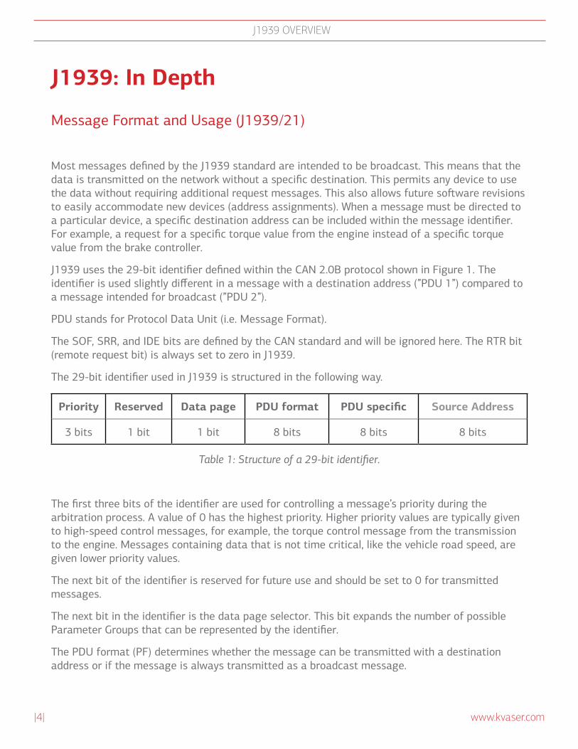
J1939 uses the 29-bit identifier defined within the CAN 2.0B protocol shown in Figure 1. The identifier is used slightly different in a message with a destination address (”PDU 1”) compared to a message intended for broadcast (”PDU 2”).
PDU stands for Protocol Data Unit (i.e. Message Format).
The SOF, SRR, and IDE bits are defined by the CAN standard and will be ignored here. The RTR bit (remote request bit) is always set to zero in J1939.
The 29-bit identifier used in J1939 is structured in the following way.
Priority Reserved Data page PDU format PDU specific Source Address
3 bits 1 bit 1 bit 8 bits 8 bits 8 bits
Table 1: Structure of a 29-bit identifier.
The first three bits of the identifier are used for controlling a message’s priority during the arbitration process. A value of 0 has the highest priority. Higher priority values are typically given to high-speed control messages, for example, the torque control message from the transmission to the engine. Messages containing data that is not time critical, like the vehicle road speed, are given lower priority values.
The next bit of the identifier is reserved for future use and should be set to 0 for transmitted messages.
The next bit in the identifier is the data page selector. This bit expands the number of possible Parameter Groups that can be represented by the identifier.
The PDU format (PF) determines whether the message can be transmitted with a destination address or if the message is always transmitted as a broadcast message.
|5| www.kvaser.com
J1939 OVERVIEW
The interpretation of the PDU specific (PS) field changes based on the PF value:
• If the PF is between 0 and 239, the message is addressable (PDU1) and the PS field contains the destination address.
• If the PF is between 240 and 255, the message can only be broadcast (PDU2) and the PS field contains a Group Extension.
The Group extension expands the number of possible broadcast Parameter Groups that can be represented by the identifier.
The term Parameter Group Number (PGN) is used to refer to the value of the Reserve bit, DP, PF, and PS fields combined into a single 18 bit value.
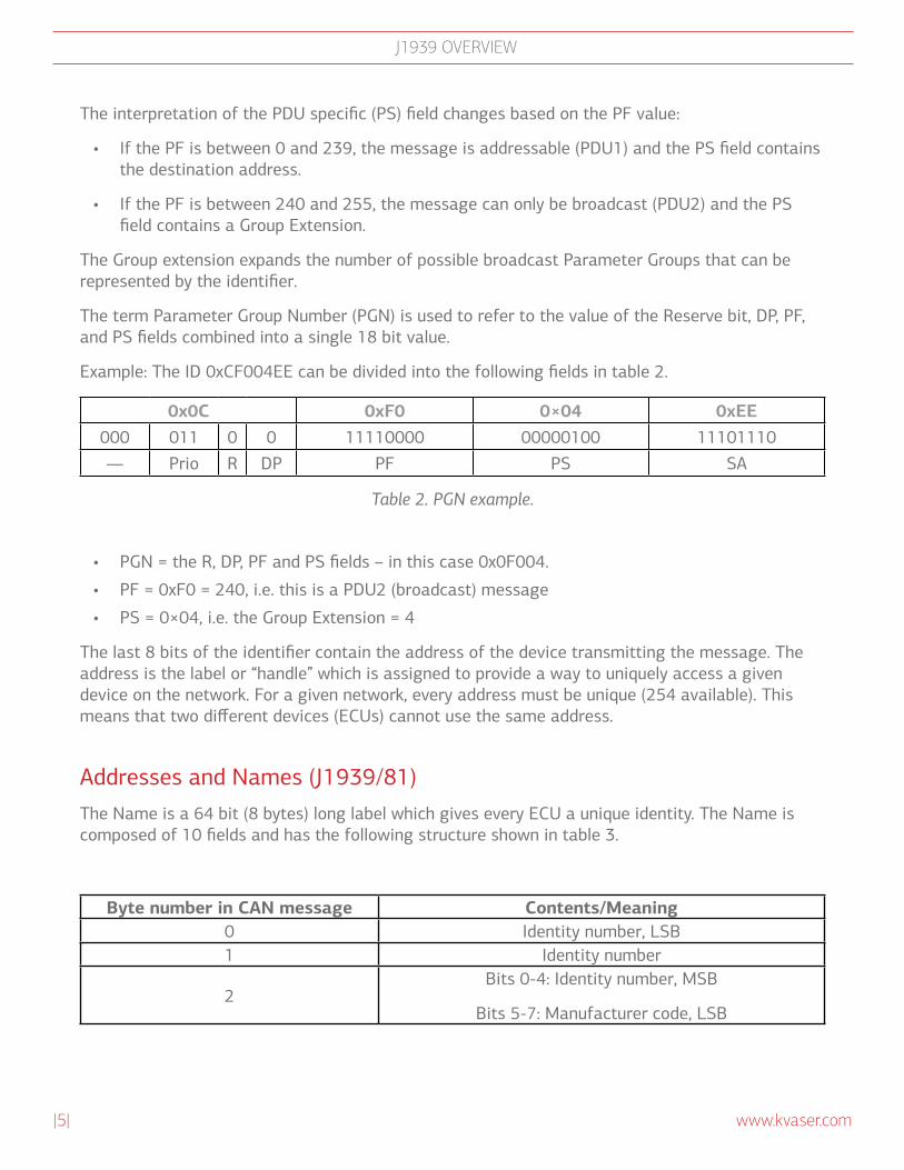
Example: The ID 0xCF004EE can be divided into the following fields in table 2.
0x0C 0xF0 0×04 0xEE000 011 0 0 11110000 00000100 11101110— Prio R DP PF PS SA
Table 2. PGN example.
• PGN = the R, DP, PF and PS fields – in this case 0x0F004.
• PF = 0xF0 = 240, i.e. this is a PDU2 (broadcast) message
• PS = 0×04, i.e. the Group Extension = 4
The last 8 bits of the identifier contain the address of the device transmitting the message. The address is the label or “handle” which is assigned to provide a way to uniquely access a given device on the network. For a given network, every address must be unique (254 available). This means that two different devices (ECUs) cannot use the same address.
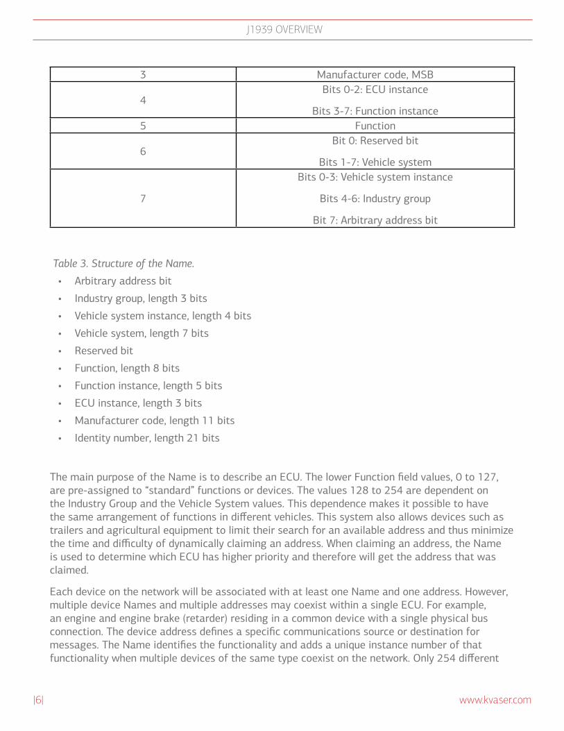
Addresses and Names (J1939/81)The Name is a 64 bit (8 bytes) long label which gives every ECU a unique identity. The Name is composed of 10 fields and has the following structure shown in table 3.
Byte number in CAN message Contents/Meaning0 Identity number, LSB1 Identity number
2Bits 0-4: Identity number, MSB
Bits 5-7: Manufacturer code, LSB
|6| www.kvaser.com
J1939 OVERVIEW
3 Manufacturer code, MSB
4Bits 0-2: ECU instance
Bits 3-7: Function instance5 Function
6Bit 0: Reserved bit
Bits 1-7: Vehicle system
7
Bits 0-3: Vehicle system instance
Bits 4-6: Industry group
Bit 7: Arbitrary address bit
Table 3. Structure of the Name.
• Arbitrary address bit
• Industry group, length 3 bits
• Vehicle system instance, length 4 bits
• Vehicle system, length 7 bits
• Reserved bit
• Function, length 8 bits
• Function instance, length 5 bits
• ECU instance, length 3 bits
• Manufacturer code, length 11 bits
• Identity number, length 21 bits
The main purpose of the Name is to describe an ECU. The lower Function field values, 0 to 127, are pre-assigned to “standard” functions or devices. The values 128 to 254 are dependent on the Industry Group and the Vehicle System values. This dependence makes it possible to have the same arrangement of functions in different vehicles. This system also allows devices such as trailers and agricultural equipment to limit their search for an available address and thus minimize the time and difficulty of dynamically claiming an address. When claiming an address, the Name is used to determine which ECU has higher priority and therefore will get the address that was claimed.
Each device on the network will be associated with at least one Name and one address. However, multiple device Names and multiple addresses may coexist within a single ECU. For example, an engine and engine brake (retarder) residing in a common device with a single physical bus connection. The device address defines a specific communications source or destination for messages. The Name identifies the functionality and adds a unique instance number of that functionality when multiple devices of the same type coexist on the network. Only 254 different
|7| www.kvaser.com
J1939 OVERVIEW
devices of the same type can coexist on the network due the address limit. Address 255 is reserved as a global address for broadcast and address 254 is reserved as the “null address” used by devices that have not yet claimed an address or failed to claim an address.
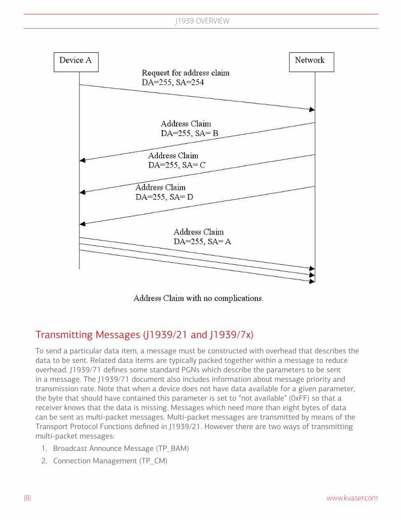
Address ClaimIn general, most addresses are pre-assigned and used immediately upon power up. In order to permit J1939 to accommodate future devices and functions which have not yet been defined, a procedure has been specified for dynamically assigning addresses. Each device must announce which address it is associated with. This is the identification (address claim) feature. Two options are available:
1. Send an Address Claim message to claim an address.
When a device sends an Address Claim message to claim an address, all devices compare this newly claimed address to their own table of devices on the network. If the address is already claimed by a device with a higher priority, that device transmits an Address Claim message indicating that the address is already in use. The Name, which is sent as data in the Address Claim message, determines which device has higher priority.
2. Send a Request for Address Claim.
When a device sends a Request for Address Claim, all devices respond by transmitting their Address Claimed messages. This permits transitional devices (tools, trailers, etc.) or devices powering up late to obtain the current address table so that an available address can be selected and claimed. See figure 2.
Dynamic address assignment support is optional and only those devices which might be expected to encounter address conflicts must support this capability. To eliminate the need to support dynamic address assignment and speed up this “identity process”, most ECUs are associated with a preferred address. These preferred addresses are described in the document J1939/71. If the preferred address is already in use by another ECU, the device can attempt to claim another address if self-configuration is supported by the device.
|8| www.kvaser.com
J1939 OVERVIEW
Transmitting Messages (J1939/21 and J1939/7x)To send a particular data item, a message must be constructed with overhead that describes the data to be sent. Related data items are typically packed together within a message to reduce overhead. J1939/71 defines some standard PGNs which describe the parameters to be sent in a message. The J1939/71 document also includes information about message priority and transmission rate. Note that when a device does not have data available for a given parameter, the byte that should have contained this parameter is set to “not available” (0xFF) so that a receiver knows that the data is missing. Messages which need more than eight bytes of data can be sent as multi-packet messages. Multi-packet messages are transmitted by means of the Transport Protocol Functions defined in J1939/21. However there are two ways of transmitting multi-packet messages:
1. Broadcast Announce Message (TP_BAM)
2. Connection Management (TP_CM)
|9| www.kvaser.com
J1939 OVERVIEW
TP_BAM messagesTP_BAM messages use a global destination address which means that all devices on the network will receive these messages. The transmission is started with a Connection Management (CM) message, PGN = 0x00EC00, with a Control byte indicating TP_BAM. The message data follows in Data Transfer (DT) messages, PGN = 0x00EB00.
TP_CM messagesTP_CM messages are sent point to point between two devices. The transmission starts with a CM message with a Control byte indicating Request To Send (RTS). The receiving device responds with a CM message with the Control byte indicating Clear To Send (CTS). The transmitting device then sends the portion of the data indicated in the CTS using DT messages. This handshake of CTS then DT messages continues until the entire message is transmitted. The connection is terminated at the completion of the message by the receiver transmitting a CM message with a Control byte indicating End Of Message Acknowledgement (EOM). Note that for this process to work, the CM message contains additional data based on what the control byte is. The RTS includes: number of bytes, number of packets and the PGN whose data will be transported. The CTS includes the number of packets the receiver expects next and the packet number to start with.
Receiving Messages (J1939/21 and J1939/7x)There are various techniques (and chips) available for capturing selected messages off the network. Several general observations can be made, however regarding received messages:
1. If a message is a destination specific request or command, the device must determine if the destination address matches an address claimed by the device. If there is a match, the receiving device must process the message and provide some type of acknowledgment.
2. If a message is a global request, every device, even the originator, must process the request and respond if the data is available.
3. If a message is broadcast, each device must determine if the content is of relevance or not.
ECU Design (J1939/1x, J1939/21, and J1939/7x)Although every manufacturer will have different performance requirements for the electronic control unit (ECU) contained within their product, several observations should be made regarding the resources needed to support J1939. The current data rate of J1939 is 250 Kbps. A typical message containing 8 data bytes is 128 bits long (excluding bits used for bit stuffing) which in time is approximately 500 microseconds. The shortest message is 64 bits long. This means that a new message could be sent every 250 microsecond. Although not every message is relevant, nor is the bus loading likely to be above 50%, the receiving processor must be able to handle (or buffer) back to back messages for short bursts of time. This will require some RAM space as well as processor time for memory transfers.
|10| www.kvaser.com
J1939 OVERVIEW
Wiring Topology – Physical Layer (J1939/1x)The J1939 network is intended to be a single, linear, shielded twisted pair of wires running around the vehicle to each ECU. A short stub is permitted between the ECU and the “bus”. This simplifies routing the main bus wiring by not requiring the main bus to connect directly to each ECU. The linear bus is necessary at a data rate of 250 Kbps in order to minimize electrical signal reflections. The termination resistor at each end of the bus also reduces reflections.
The J1939 network may actually be composed of multiple segments, with an in-line device known as a bridge present between them. These segments do not need to be directly compatible with each other. For instance, the segments may run at different data rates or use a different physical medium. The main function of the bridge is to provide electrical isolation between segments. In the event of a break on the wire between the tractor and trailer, the main J1939 segment on the tractor will continue to function. The bridge can also selectively filter which messages need to be stored and forwarded from one segment to another.
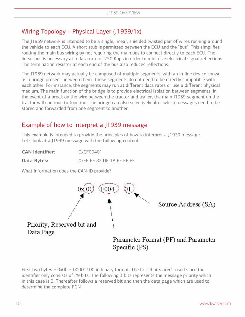
Example of how to interpret a J1939 messageThis example is intended to provide the principles of how to interpret a J1939 message. Let’s look at a J1939 message with the following content:
CAN identifier: 0xCF00401
Data Bytes: 0xFF FF 82 DF 1A FF FF FF
What information does the CAN-ID provide?
First two bytes = 0x0C = 00001100 in binary format. The first 3 bits aren’t used since the identifier only consists of 29 bits. The following 3 bits represents the message priority which in this case is 3. Thereafter follows a reserved bit and then the data page which are used to determine the complete PGN.
|11| www.kvaser.com
J1939 OVERVIEW
The last byte of the CAN-ID is the Source Address (address of the sending device) which in this case is 1.
The PGN = 0x0F004 which corresponds to the Electric Engine Controller #1 (EEC1) according to the J1939/71 document. This document also describes the parameters and their position within the data bytes. The data field consists of the following bytes in this example:
Data bytes FF FF 82 DF 1A FF FF FF
Position 1 2 3 4 5 6 7 8
Data bytes 1, 2, 6, 7 and 8 in this example are not available and are therefore set to 0xFF. No raw parameter value (single byte) could have the value 0xFF.
Data byte 3 is the parameter Actual engine percent torque. The raw value 0×82 is 130 decimal. According to the J1939/71 document the scaling 1% per bit and the offset is -125. Therefore, the actual value for this parameter is 5%.
Data bytes 4 and 5 form the parameter Engine speed. The first byte (4) is the least significant (Intel byte order). The raw value 0x1ADF = 6879 decimal. The scaling is 0.125 rpm per bit and the offset is 0. The actual value for this parameter is therefore just under 859.875 rpm.
_______________________________________________________________

|12| www.kvaser.com
J1939 OVERVIEW
Next StepsThis document introduces you to the J1939 standard with a brief overview, a guide to the SAE specification, and an in depth you look at the message architecture. Hopefully this has helped you get a picture of the world of J1939.
You may have downloaded this document for a variety of reasons. Perhaps you are designing a system or ECU, or troubleshooting vehicles, or conducting academic research. In all of these situations, there are a few simple “next steps” that will help you move forward with J1939.
Get the Complete J1939 Specification DocumentsThe complete set of specifications can be purchased directly from SAE; an overview is available on SAE’s website here.
Compare J1939 Compatible Software SuitesThere are a several powerful software suites available for logging, monitoring, and analyzing J1939 data. Some of these software suites are focused on ECU development and design, others on testing and troubleshooting.
Compare J1939 Software
Order a J1939 Diagnostic CableThe first step toward working with a J1939 bus is accessing the data. The Kvaser Leaf Light HS v2 J1939-13 is a popular and easy-to-use diagnostic cable. This Kvaser Leaf unit includes a J1939-13 connector for network access and a USB connector for the PC connection. Kvaser also provides Windows and Linux drivers, Windows monitoring software and technical support free of charge.
View the Kvaser Leaf Light HS v2 J1939-13
_______________________________________________________________
|13| www.kvaser.com
J1939 OVERVIEW
APPENDIX A
J1939/11 Physical LayerThe physical properties of the bus:
• Shielded twisted pair wire.
• Max 40 meter.
• 250 kbit/s.
• Max 30 nodes (ECUs).
• Based on ISO11898.
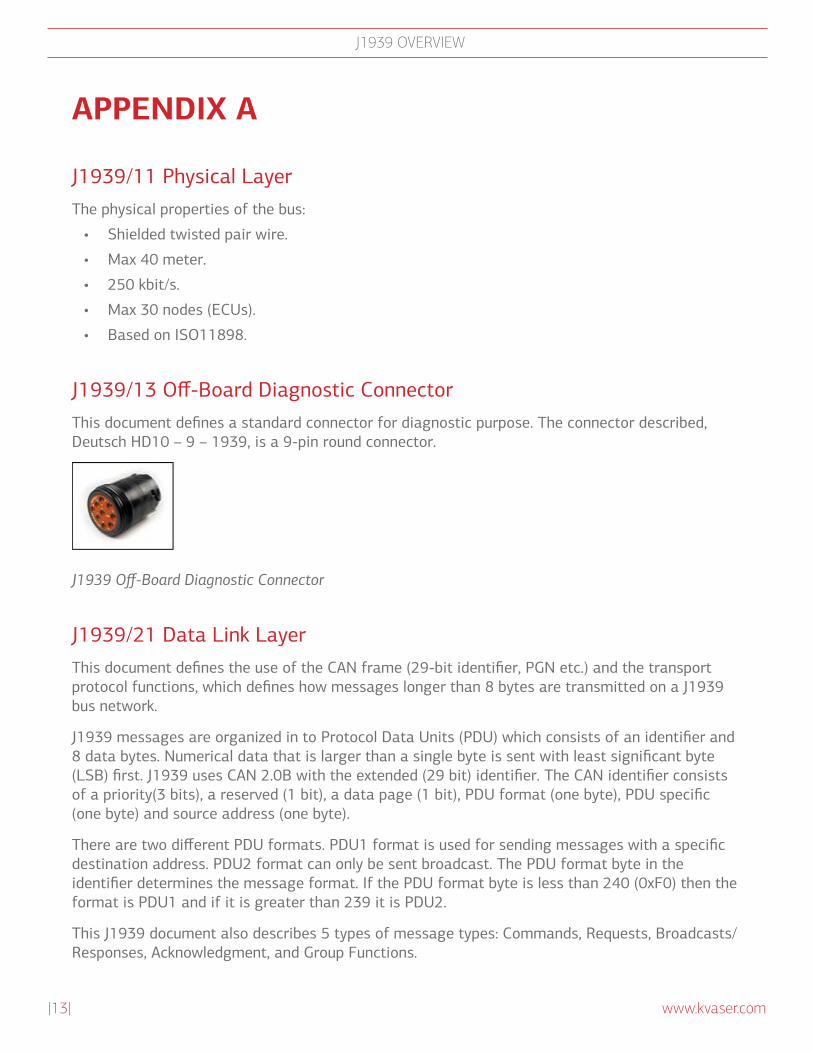
J1939/13 Off-Board Diagnostic ConnectorThis document defines a standard connector for diagnostic purpose. The connector described, Deutsch HD10 – 9 – 1939, is a 9-pin round connector.
J1939 Off-Board Diagnostic Connector
J1939/21 Data Link LayerThis document defines the use of the CAN frame (29-bit identifier, PGN etc.) and the transport protocol functions, which defines how messages longer than 8 bytes are transmitted on a J1939 bus network.
J1939 messages are organized in to Protocol Data Units (PDU) which consists of an identifier and 8 data bytes. Numerical data that is larger than a single byte is sent with least significant byte (LSB) first. J1939 uses CAN 2.0B with the extended (29 bit) identifier. The CAN identifier consists of a priority(3 bits), a reserved (1 bit), a data page (1 bit), PDU format (one byte), PDU specific (one byte) and source address (one byte).
There are two different PDU formats. PDU1 format is used for sending messages with a specific destination address. PDU2 format can only be sent broadcast. The PDU format byte in the identifier determines the message format. If the PDU format byte is less than 240 (0xF0) then the format is PDU1 and if it is greater than 239 it is PDU2.
This J1939 document also describes 5 types of message types: Commands, Requests, Broadcasts/Responses, Acknowledgment, and Group Functions.
|14| www.kvaser.com
J1939 OVERVIEW
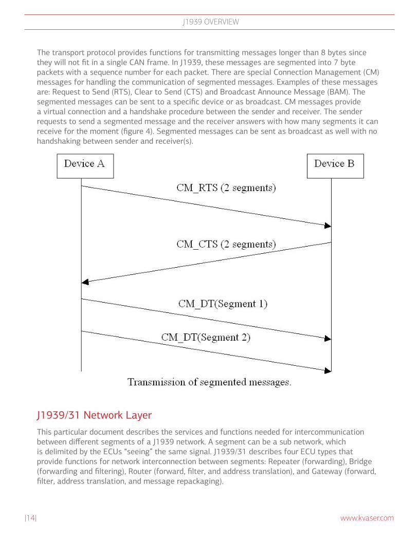
The transport protocol provides functions for transmitting messages longer than 8 bytes since they will not fit in a single CAN frame. In J1939, these messages are segmented into 7 byte packets with a sequence number for each packet. There are special Connection Management (CM) messages for handling the communication of segmented messages. Examples of these messages are: Request to Send (RTS), Clear to Send (CTS) and Broadcast Announce Message (BAM). The segmented messages can be sent to a specific device or as broadcast. CM messages provide a virtual connection and a handshake procedure between the sender and receiver. The sender requests to send a segmented message and the receiver answers with how many segments it can receive for the moment (figure 4). Segmented messages can be sent as broadcast as well with no handshaking between sender and receiver(s).
J1939/31 Network LayerThis particular document describes the services and functions needed for intercommunication between different segments of a J1939 network. A segment can be a sub network, which is delimited by the ECUs “seeing” the same signal. J1939/31 describes four ECU types that provide functions for network interconnection between segments: Repeater (forwarding), Bridge (forwarding and filtering), Router (forward, filter, and address translation), and Gateway (forward, filter, address translation, and message repackaging).
|15| www.kvaser.com
J1939 OVERVIEW
J1939/71 Vehicle Application LayerThis document describes and defines “standard” parameters which are grouped together in a message frame and given a PGN. This document is updated approximately four times a year to include new standard parameters and messages.
There are different lengths of parameters defined in the document; 1, 2, 4 bytes. If the most significant byte of a parameter has the value 0xFE this indicates an error and if the value is 0xFF this indicates that the parameter is not available. This document also recommends appropriate scaling, limits and offset depending on the length and the physical property of a parameter.
A parameter’s description starts with a name and an explanation of the value to be represented (i.e. method of measurement used to obtain the parameter value). The following information then describes the content of the parameter:
• Data length (bytes)
• Resolution (scaling and offset, unit of measurement)
• Data range (range of the physical value, after scaling)
• Type (status, measured value )
• Suspect Parameter Number (SPN) (parameter specific number)
• PGN (reference to the message frame it is sent in)
Every Parameter Group is described with a name and then the following information:
Transmission repetition rate (a time interval or on request)
• Data length (bytes)
• Data page (0 or 1, has to do with the PGN)
• PDU format (0 to 255, has to do with the PGN)
• PDU specific (depends on PDU format)
• Default priority (value between 0 and 7 where 0 is the highest priority)
• Parameter Group Number (PGN)
• Data parameter bytes (all parameters included with reference and byte order)
Most of the internal messages are sent as broadcast without a specific destination address.
J1939/73 Application Layer – DiagnosticsThis document defines functions and messages for accessing diagnostic and calibration data. There is a number of predefined Diagnostic Messages (DM) used for:
• Reading and writing to ECU memory
• Reporting diagnostic information when running
• Identification of lamp status
|16| www.kvaser.com
J1939 OVERVIEW
• Reading and clearing Diagnostic Trouble Codes (DTCs)
• Start/stop broadcast DMs
Newer versions of this document include additional information regarding the interpretation of Diagnostic Trouble Codes (DTC). The DTC is a 32 bit identifier inherited from J1587 and consists of 4 elements: Suspect Parameter Number (SPN), Failure Mode Identifier (FMI), Occurrence Count (OC) and SPN Conversion Method. The DTC together with the source address identifies a component or sub system.
J1939/81 Network ManagementThis document contains information about the content of an ECU Name and how the ECU claims an addressing using that Name. The Name is a 64 bit (8 bytes) long number that gives every ECU a unique identity. The name has two main purposes:
1. Provide a description of an ECU, including function.
2. Serve as a numerical value that can be used for arbitration when claiming an address.
The J1939/81 document also describes how the address claim process works. There are basically three types of messages for this purpose defined in the document.
1. Request for Address Claimed (PGN 59904) which is sent to retrieve information about addresses being used by other devices on the network.
2. Address Claimed (PGN 60928) which can be divided into:
1. Address Claimed, which is sent to claim an address or as a response to the “Request for Address Claimed” message to indicate the address of a device. The Source address is set to the address that is claimed.
2. Address Cannot Claim, which is sent when the ECU fails the address claim process. If the ECU has failed the address claim process and receives a “Request for Address Claimed” message, Address Cannot Claim is sent in response. The Source Address is set to 254 to indicate no address.
3. Commanded Address (PGN 65240) which is used to set an ECU to a specific address. This can be done by a diagnostic tool or an interconnecting ECU (bridge, gateway).
When arbitration for an address is performed, the Name is treated as an 8 byte numerical value where the lower the value, the higher the priority.
_______________________________________________________________


![DCU 305 R3 CAN / J1939 Manual - Auto-Maskin§ [a] SAE, J1939-71 § [b] SAE, J1939-73 § [c] Conrad Etschberger, “Controller Area Network” ... CAN / J1939 Manual CAN / J1939 –](https://img.pdfslide.us/doc/110x75/5ae535d97f8b9a7b218f6863/dcu-305-r3-can-j1939-manual-auto-maskin-a-sae-j1939-71-b-sae-j1939-73.jpg)