Embed Size (px)
Citation preview
Maine State LibraryDigital Maine
All Bureau of Labor Standards Documents Bureau of Labor Standards
2-1-1999
1926 Construction: Machine Guarding and Handand Power Tool Safety, Feb. 1999Labor/Labor Standards
Follow this and additional works at: http://digitalmaine.com/bls_docs
This Text is brought to you for free and open access by the Bureau of Labor Standards at Digital Maine. It has been accepted for inclusion in All Bureauof Labor Standards Documents by an authorized administrator of Digital Maine. For more information, please contact [email protected].
Recommended CitationLabor/Labor Standards, "1926 Construction: Machine Guarding and Hand and Power Tool Safety, Feb. 1999" (1999). All Bureau ofLabor Standards Documents. 615.http://digitalmaine.com/bls_docs/615
1926 CONSTRUCTIONMACHINE GUARDING
AND
HAND AND POWER TOOL SAFETY
Safety Works!MAINE DEPARTMENT OF LABOR
2/99
SUBPART I - Tools - Hand and Power
1926.300 General Requirements
a. Condition of tools.
b. Guarding.
c. Personal Protective Equipment.
d. Switches.
1926.301 Hand Tools
a. Employers shall not issue or permit the use of unsafe tools.
b. Wrenches, including adjustable, pipe, end and socket wrenches, shall not be used when jaws are sprung to the point that slippage may occur.
c. Impact tools, such as drift pins, wedges and chisels shall be kept free of mushroomed heads.
d. The wooden handles of tools shall be kept free of splinters or cracks and shall be kept tight in the tool.
1
1926.302 Power operated hand tools
a. Electric power operated tools.
b. Pneumatic power tools.
c. Fuel powered tools.
d. Hydraulic power tools.
e. Powder actuated tools.
1926.303 Abrasive wheels and tools
a. Sufficient power supply.
b. Guarding.
c. Use of abrasive wheels.
d. Other requirements.
1926.304 Woodworking tools.
a. Disconnect switches.
b. Speeds.
c. Self feed.
d. Guarding.
e. Other requirements - ANSI.
2
MACHINE GUARDING “General Duty Clause”
OSHA STANDARD 1910.212(a)(1):
“One or more methods of machine guarding must be provided to protect the operator and other employees in the machine area from hazards such as those created by points of operation, ingoing nip points, rotating parts, flying chips and sparks.”
TRANSLATION:
All moving parts of machines must be guarded if exposed to employee contact.
3
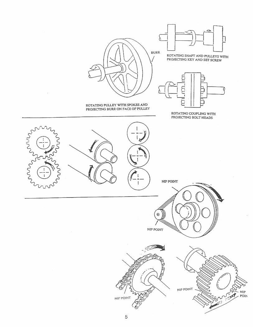
MECHANICAL POWER TRANSMISSION APPARATUS:
"The drive mechanism on any machine or power tool which connects the motor to the area where work is actually performed upon the material being processed."
EXAMPLES INCLUDE:
* Belts and Pulleys
* Chains and Sprockets
* Gears and Rocker Arms
* Shafts and Couplings
* Spindles and Flywheels
* Other reciprocating, rotating or moving parts
4
5
ROTATING SHAFT AND PULLEYS WITH PROJECTING KEY AND SET SCREW
ROTATING PULLEY WITH SPOKES AND PROJECTING BURR ON FACE OF PULLEY
ROTATING COUPLING WITH PROJECTING BOLT HEADS
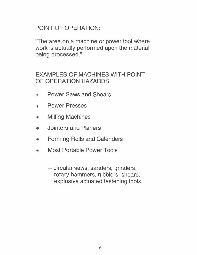
POINT OF OPERATION:
“The area on a machine or power tool where work is actually performed upon the material being processed.”
EXAMPLES OF MACHINES WITH POINT OF OPERATION HAZARDS
* Power Saws and Shears
* Power Presses
* Milling Machines
* Jointers and Planers
* Forming Rolls and Calenders
* Most Portable Power Tools
-- circular saws, sanders, grinders, rotary hammers, nibblers, shears, explosive actuated fastening tools
6
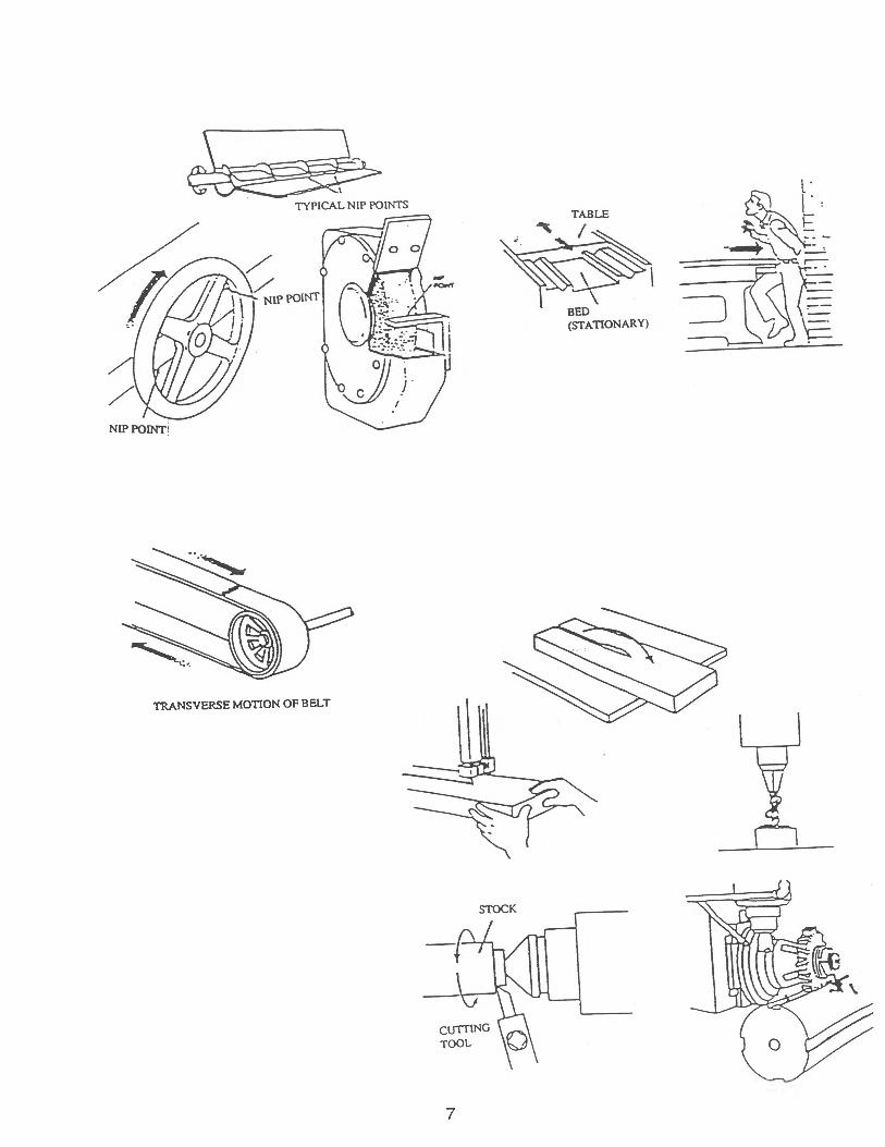
7
TRANSVERSE MOTION OF BELT

1910.213 WOODWORKING MACHINERY REQUIREMENTS:
Machine Controls:
1. Power switch so located on each machine to allow the operator to cut off power without leaving his/her position at the point of operation.
2. On applications where injury to the operator might result if motors were to restart after power failures, provision shall be made to prevent machines from automatically restarting upon restoration of power (i.e. magnetic restarts).
3. All power and operating controls to be located within easy reach of the operator while at his/her regular work location.
8

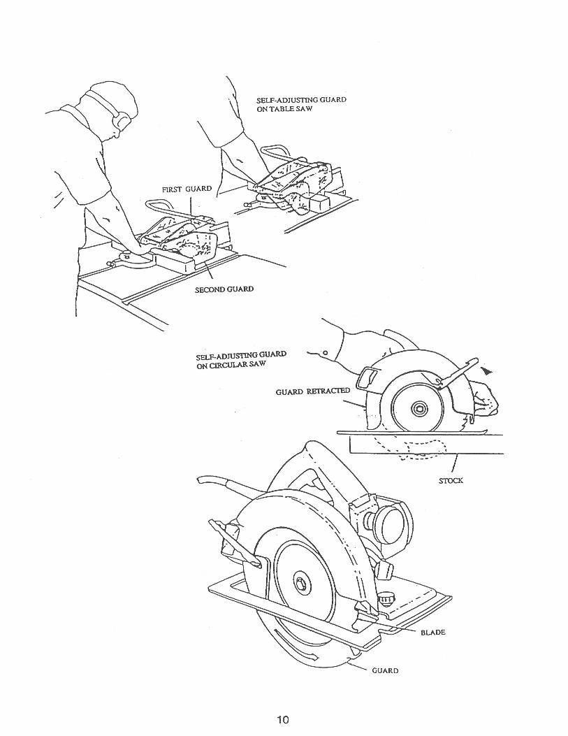
TABLE SAWS / RIP SAWS
Must have:
1. Exposed portions of blades guarded by an automatically adjusting hood;
2. Spreader installed at rear of blade to prevent material from squeezing the saw and/or being thrown back toward the operator.
3. Nonkickback fingers or dogs installed and located as to oppose the thrust or tendency of the saw to pick up material or to throw it back toward the operator;
4. All drive belts and pulleys covered by guards.
9
10
SELF-ADJUSTING GUARDON TABLE SAW
SELF-ADJUSTING GUARD ON CIRCULAR SAW
11
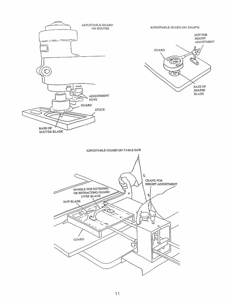
ADJUSTABLE GUARD ON SHAPER
ADJUSTABLE GUARD ON TABLE SAW
ADJUSTABLE GUARDON ROUTER
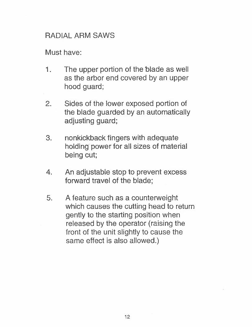
RADIAL ARM SAWS
Must have:
1. The upper portion of the blade as well as the arbor end covered by an upper hood guard;
2. Sides of the lower exposed portion of the blade guarded by an automatically adjusting guard;
3. nonkickback fingers with adequate holding power for all sizes of material being cut;
4. An adjustable stop to prevent excess forward travel of the blade;
5. A feature such as a counterweight which causes the cutting head to return gently to the starting position when released by the operator (raising the front of the unit slightly to cause the same effect is also allowed.)
12
13
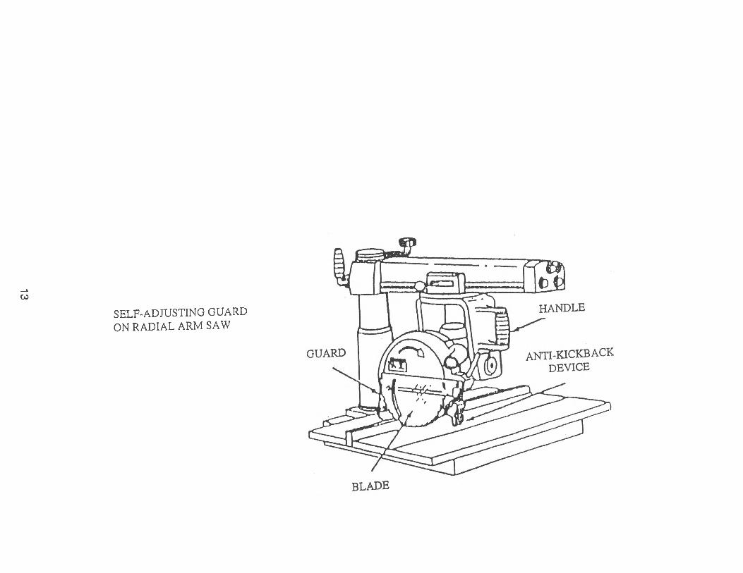
SELF-ADJUSTING GUARD ON RADIAL ARM SAW
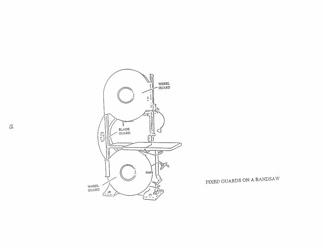
BANDSAWS
Must have:
1. All portions of the saw blade enclosed or guarded except for the working portion of the blade between the bottom of the guide rolls and the table;
2. Bandsaw wheels fully encased by guards of solid material or mesh with openings greater than three-eights inch;
3. A blade tension control device to indicate proper tension for the standard saws used on the machine.
14
15
FIXED GUARDS ON A BANDSAW
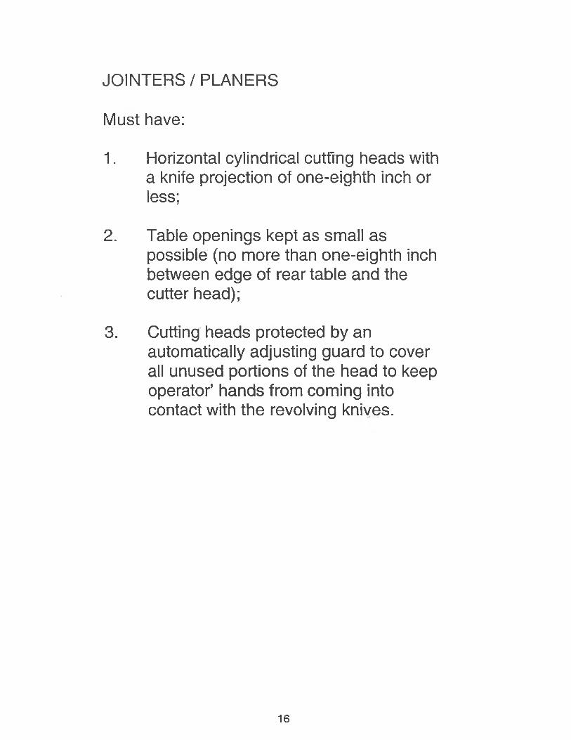
JOINTERS / PLANERS
Must have:
1. Horizontal cylindrical cutting heads with a knife projection of one-eighth inch or less;
2. Table openings kept as small as possible (no more than one-eighth inch between edge of rear table and the cutter head);
3. Cutting heads protected by an automatically adjusting guard to cover all unused portions of the head to keep operator’ hands from coming into contact with the revolving knives.
16
SELF-ADJUSTING GUARD ON A JOINTER
17
SELF-ADJUSTING GUARD ON A JOINTER
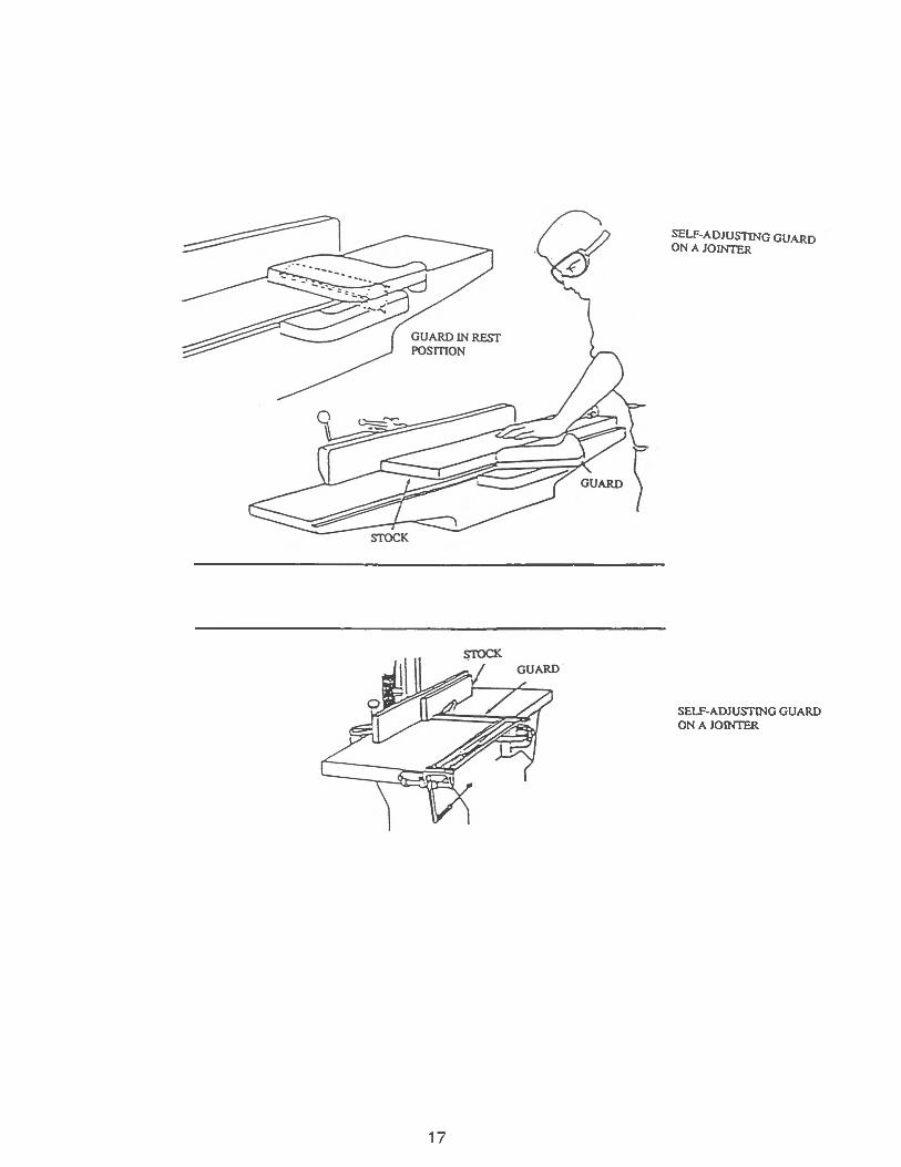
WOOD LATHES
Must have:
1. Long curved guards extending over the top of the lathe in order to prevent the work pieces from being thrown out of the machine if they should become loose.
SANDING MACHINES
1. Disk sanders must have a guard so arranged as to enclose the shaft and unused portion of the disk below the table.
2. Belt sanders must have guards at each nip point where the sanding belt runs onto a pulley.
18
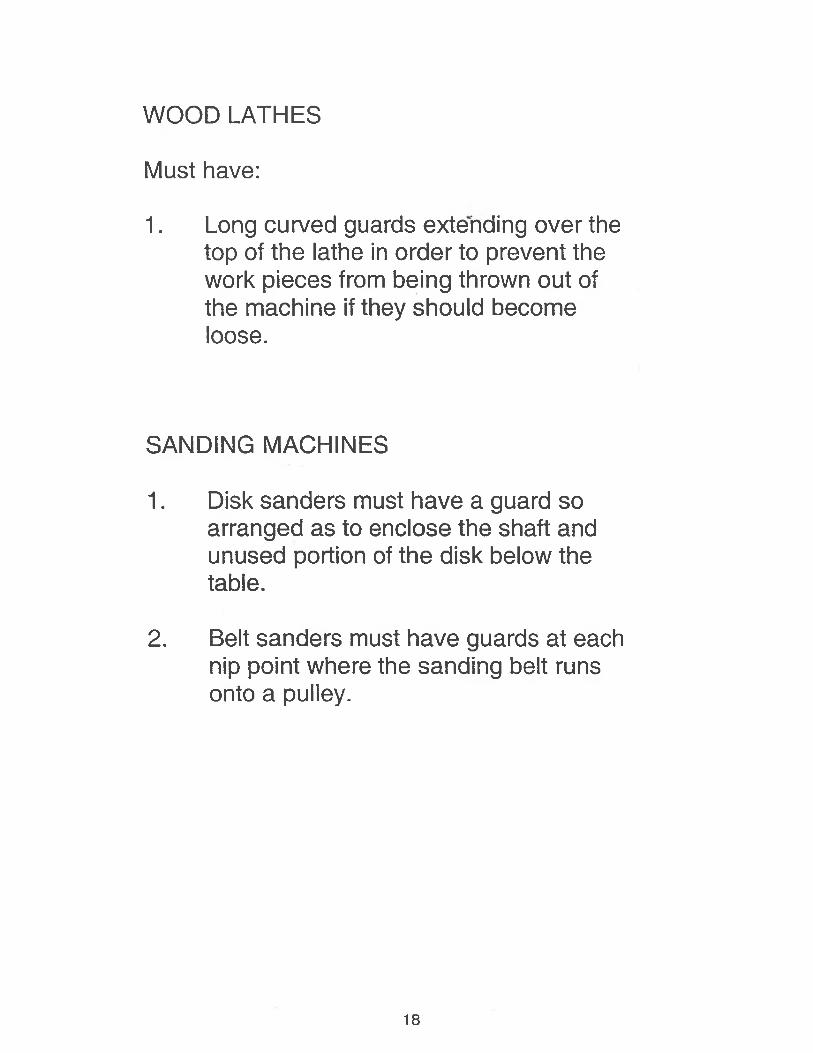
Holding tools can place or remove stock.
A push stick or block, such as those in below, may be used when feeding stock into a saw blade. When it becomes necessary for hands to be in close proximity to the blade, the push stick or block may provide a few inches of safety and prevent a severe injury. In the illustration the push block fits over the fence.
19
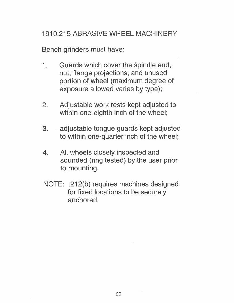
1910.215 ABRASIVE WHEEL MACHINERY
Bench grinders must have:
1. Guards which cover the spindle end, nut, flange projections, and unused portion of wheel (maximum degree of exposure allowed varies by type);
2. Adjustable work rests kept adjusted to within one-eighth inch of the wheel;
3. adjustable tongue guards kept adjusted to within one-quarter inch of the wheel;
4. All wheels closely inspected and sounded (ring tested) by the user prior to mounting.
NOTE: .212(b) requires machines designed for fixed locations to be securely anchored.
20
Inspections. Handling and Storage of Abrasive Disks and Wheels
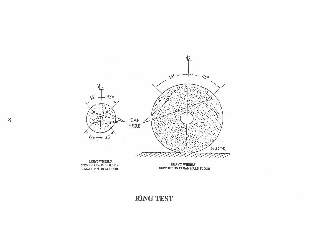
While they are being unpacked abrasive disks and wheels should be inspected for shipment damage and then, given the “ring” test by a qualified person. This test can be used for both light and heavy disks or wheels that are dry and free of foreign material. To conduct the ring test, a light disk or wheel should be suspended from its hole on a small pin or the finger, and a heavy one should be placed vertically on a hard floor. Then the wheel or disk should be gently tapped with light tool, such as a wooden screwdriver handle. A mallet may be used for heavy wheels or disks. The tap should be made at a point 45 degrees from the vertical centerline and about 1 or 2 in. (2.5-5 cm) from the periphery. A wheel or disk in good condition will give a clear, metallic ring when tapped. A clear ring indicates good condition. Wheels and disks of various grades and sizes give different pitches.
Daily inspection of grinding machines should include those points necessary to safe operation.
Abrasive disks and wheels require careful handling. They should not be dropped or bumped. Large disks and wheels should not be rolled on the floor. Disks and wheels too large or heavy to be hand-carried should be transported by truck or other conveyance that provides the correct support.
Store abrasive disks and wheels in a dry area not subject to extreme temperature changes, especially below-freezing temperatures. Wet wheels might break or crack if stored below 32° F.
Breakage can occur if a wheel or disk is taken from a cold room and work is applied to it before it has warmed up. Abrasive disks and wheels should be stored in racks in a central storage area (Figure 10-14) under the control of a specially trained person.The storage area should be as close as possible to grinding operations to minimize handling and transportation.
The length of time abrasive disks and wheels may be stored and still be safe to use should be in accordance with manufacturers’ recommendations. Disks and wheels taken out of long storage should be given the ring test. Follow this by a check for recommended speed, and a speed test on the machine on which they will be mounted. Check the speed of all grinding wheels against the spindle speed of the machine; some are designed only for low-speed use.
21
22
LIGHT WHEELS SUSPEND FROM HOLE BY SMALL PIN OR ANCHOR
HEAVY WHEELSSUPPORT ON CLEAN HARD FLOOR
RING TEST
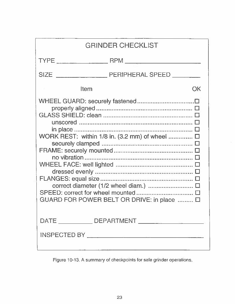
GRINDER CHECKLIST
TYPE_______________RPM ___ ___________________
SIZE _______________PERIPHERAL SPEED________
DATE__________DEPARTMENT___________________
INSPECTED BY__________________________________
Figure 10-13. A summary of checkpoints for safe grinder operations.
23
Item OK
WHEEL GUARD: securely fastened................................. □properly aligned..........................................................□
GLASS SHIELD: clean..................................................... □unscored....................................................................□in place.......................................................................□
WORK REST: within 1/8 in. (3.2 mm) of wheel...............□securely clamped...................................................... □
FRAME: securely mounted............................................... □no vibration.................................................................□
WHEEL FACE: well lighted.............................................. □dressed evenly...........................................................□
FLANGES: equal size....................................................... □correct diameter (1/2 wheel diam .)........................... □
SPEED: correct for wheel mounted................................ □GUARD FOR POWER BELT OR DRIVE: in place ..........□
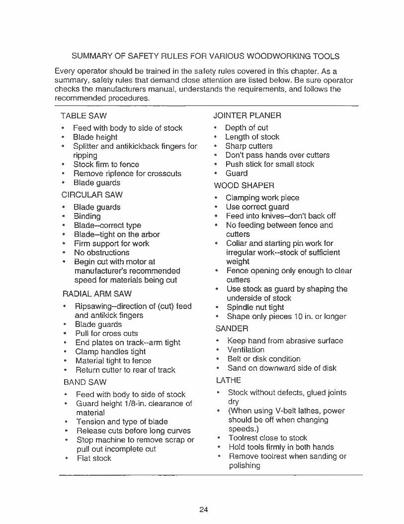
SUMMARY OF SAFETY RULES FOR VARIOUS WOODWORKING TOOLS
Every operator should be trained in the safety rules covered in this chapter. As a summary, safety rules that demand close attention are listed below. Be sure operator checks the manufacturers manual, understands the requirements, and follows the recommended procedures.
TABLE SAW• Feed with body to side of stock• Blade height• Splitter and antikickback fingers for
ripping• Stock firm to fence• Remove ripfence for crosscuts• Blade guardsCIRCULAR SAW• Blade guards• Binding• Blade-correct type• Blade-tight on the arbor• Firm support for work• No obstructions• Begin cut with motor at
manufacturer’s recommended speed for materials being cut
RADIAL ARM SAW• Ripsawing-direction of (cut) feed
and antikick fingers• Blade guards• Pull for cross cuts• End plates on track-arm tight• Clamp handles tight• Material tight to fence• Return cutter to rear of trackBAND SAW• Feed with body to side of stock• Guard height 1/8-in. clearance of
material• Tension and type of blade• Release cuts before long curves• Stop machine to remove scrap or
pull out incomplete cut• Flat stock
JOINTER PLANER• Depth of cut• Length of stock• Sharp cutters• Don’t pass hands over cutters• Push stick for small stock• GuardWOOD SHAPER• Clamping work piece• Use correct guard• Feed into knives-don’t back off• No feeding between fence and
cutters• Collar and starting pin work for
irregular work-stock of sufficient weight
• Fence opening only enough to clear cutters
• Use stock as guard by shaping the underside of stock
• Spindle nut tight• Shape only pieces 10 in. or longerSANDER• Keep hand from abrasive surface• Ventilation• Belt or disk condition• Sand on downward side of diskLATHE• Stock without defects, glued joints
dry• (When using V-belt lathes, power
should be off when changing speeds.)
• Toolrest close to stock• Hold tools firmly in both hands• Remove toolrest when sanding or
polishing
24
1910.242 HAND AND PORTABLE POWERED TOOLS AND EQUIPMENT
(a) General Requirements:
Each employer shall be responsible for the safe condition of tools and equipment used by employees, including those which may be furnished by employees.
TO PREVENT INJURIES:
1. Tools must be maintained in good condition, i.e. no cracked wooden handles and no mushroomed heads.
2. Employees must be instructed to use the proper tool for the job, i.e. screwdriver vs. chisel, wrench vs. pliers, etc.
25

TYPES OF MACHINE SAFEGUARDING DEVICES:
♦ Presence Sensing Device
♦ Gate or Movable Barrier
♦ Fixed Barrier Guard
♦ Adjustable Barrier Guard
♦ Holdout or Restraint Device
♦ Pull-out Device
♦ Sweep Device
♦ Electrical Interlocks
♦ Pressure Pads and Trip Wires
♦ Two Hand Control Devices
♦ Hand-held Feeding Tools
26
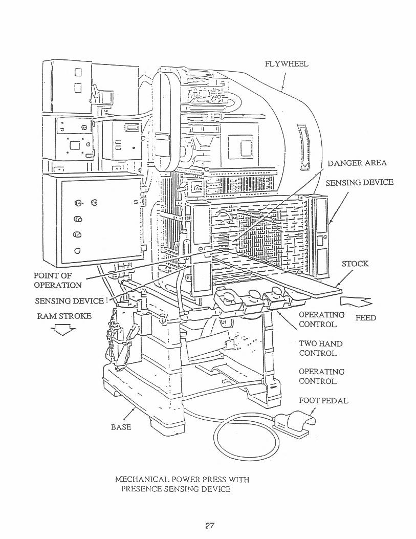
MECHANICAL POWER PRESS WITH PRESENCE SENSING DEVICE
27
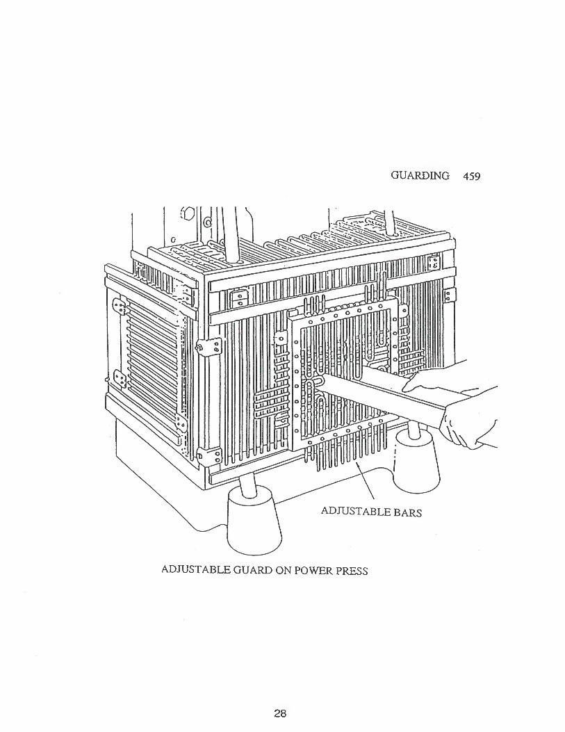
GUARDING 459
ADJUSTABLE GUARD ON POWER PRESS
28
29
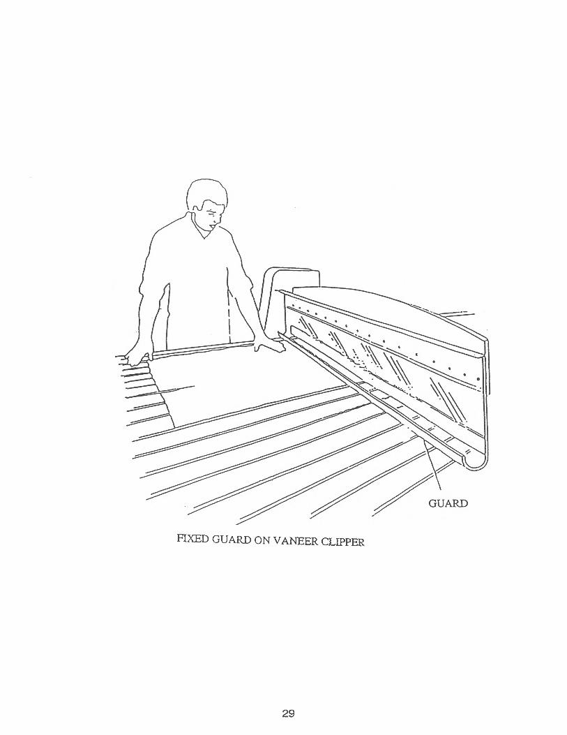
FIXED GUARD ON VANEER CLIPPER
30
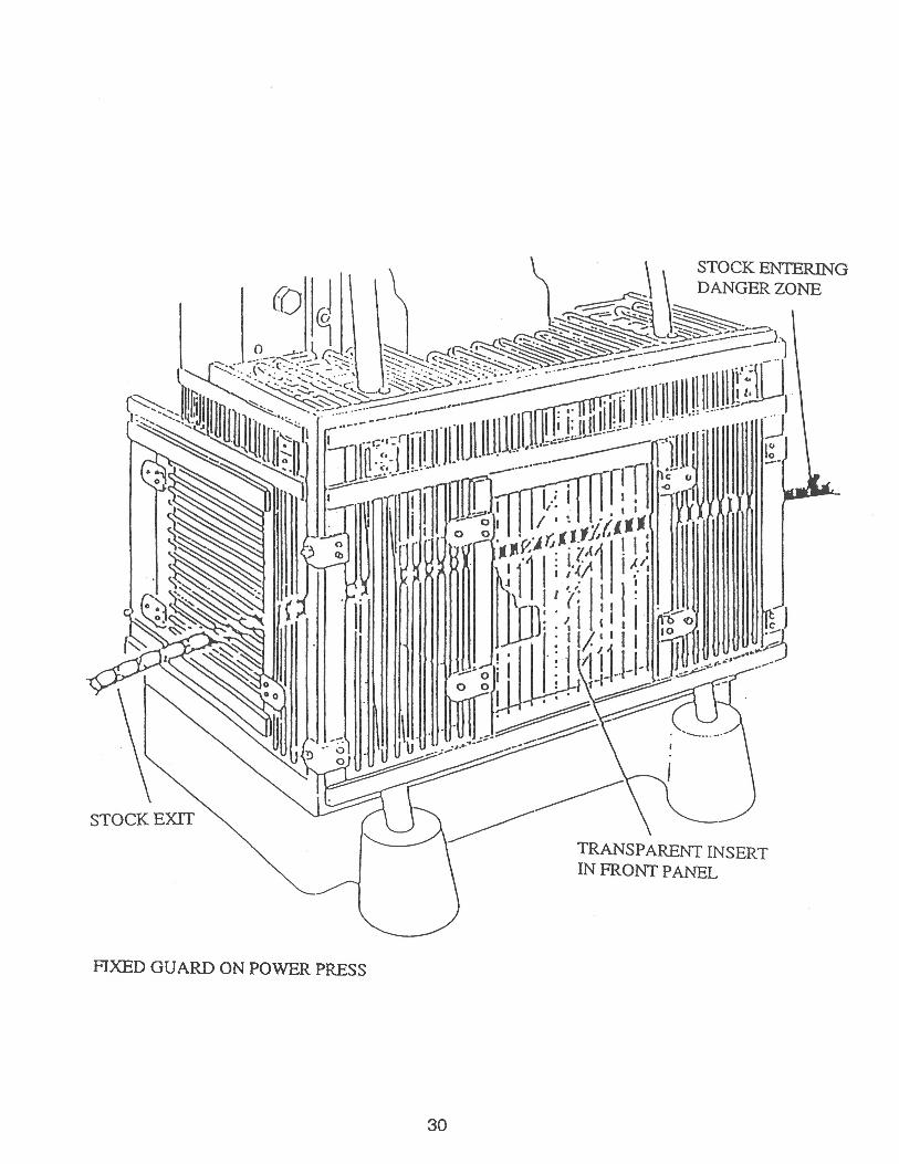
FIXED GUARD ON POWER PRESS
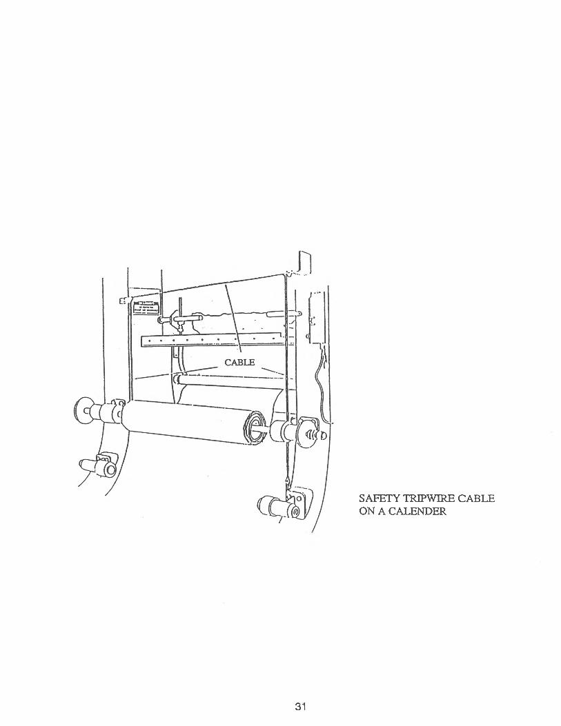
SAFETY TRIPWIRE CABLE ON A CALENDER
31
32
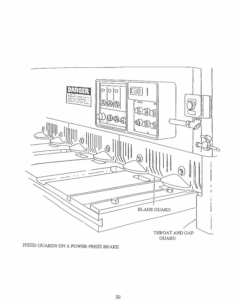
FIXED GUARDS ON A POWER PRESS BRAKE
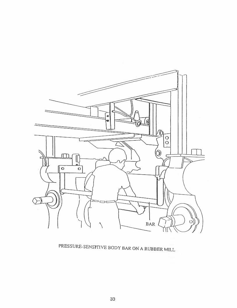
PRESSURE-SENSITIVE BODY BAR ON A RUBBER MILL
33

MAINED E P A R T M E N T O F
LABORLabor Standards
45 State House Station Augusta, Maine 04333-0045
TEL: (207) 624-6400 FAX: (207) 624-6449