Embed Size (px)
Citation preview
(19) United States (12) Patent Application Publication (10) Pub. No.: US 2015/0371658 A1
US 20150371658A1
Gao (43) Pub. Date: Dec. 24, 2015
(54) CONTROL OF ACOUSTIC ECHO (52) U.S. Cl. CANCELLERADAPTIVE FILTER FOR CPC ............ G10L 21/0208 (2013.01); G10K 1 1/16 SPEECHENHANCEMENT (2013.01)
(71) Applicant: Yang Gao, Mission Viejo, CA (US) (57) ABSTRACT A method for cancelling/reducing acoustic echoes in speech/
(72) Inventor: Yang Gao, Mission Viejo, CA (US) audio signal enhancement processing comprises using a received reference signal to excite an adaptive filter wherein
(73) Assignee: Yang Gao, Mission Viejo, CA (US) the output of the adaptive filter forms a replica signal of acoustic echo; an adaptation step size is controlled for updat
(21) Appl. No.: 14/740,718 ing the coefficients of the adaptive filter; the adaptation step 1-1. size is initialized by using an open-loop approach and opti
(22) Filed: Jun. 16, 2015 mized by using a closed-loop approach; one of the most O O important parameters with the open-loop approach is an
Related U.S. Application Data energy ratio between an energy of a returned echo signal in an (60) Provisional application No. 62/014,359, filed on Jun. input microphone signal and an energy of the received refer
19, 2014. ence signal; one of the most important parameters with the closed-loop approach is a normalized correlation or a square
Publication Classification of the normalized correlation between the input microphone signal and the replica signal of acoustic echo; the replica
(51) Int. Cl. signal of acoustic echo is Subtracted from the microphone GIOL 2L/0208 (2006.01) input signal to Suppress the acoustic echo in the microphone GIOK II/I6 (2006.01) input signal.
Tx
Noise Signal
N Simplified Adaptive
Spccch -Y Beam forming
Echo
G
704 - - Replica Signal
Adaptation Stepsize Control
Adaptive Filter h(n)
703 Rx Signal
US 2015/0371658 A1 Dec. 24, 2015 Sheet 1 of 11 Patent Application Publication
| 0 ||
().IV-0.Id) q000dS ?SION
US 2015/0371658 A1 Dec. 24, 2015 Sheet 2 of 11 Patent Application Publication
z 9.InáH
ZOZ
| 07
().IV-0.Id) q000dS ?SION
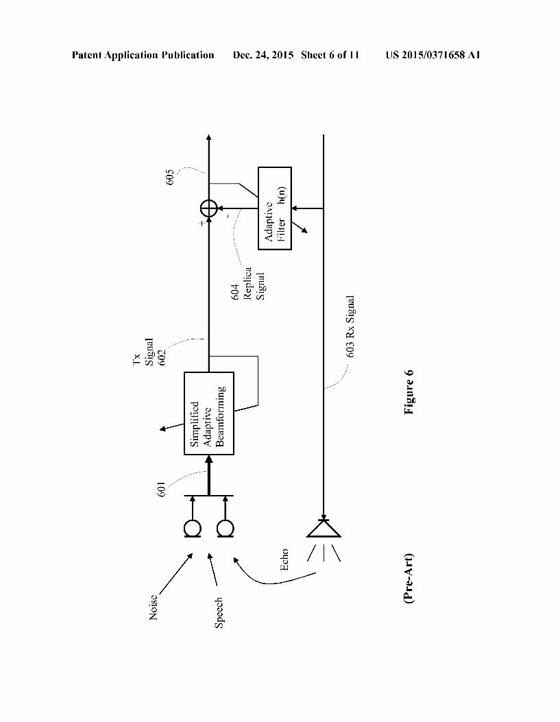
US 2015/0371658 A1 Dec. 24, 2015 Sheet 3 of 11 Patent Application Publication
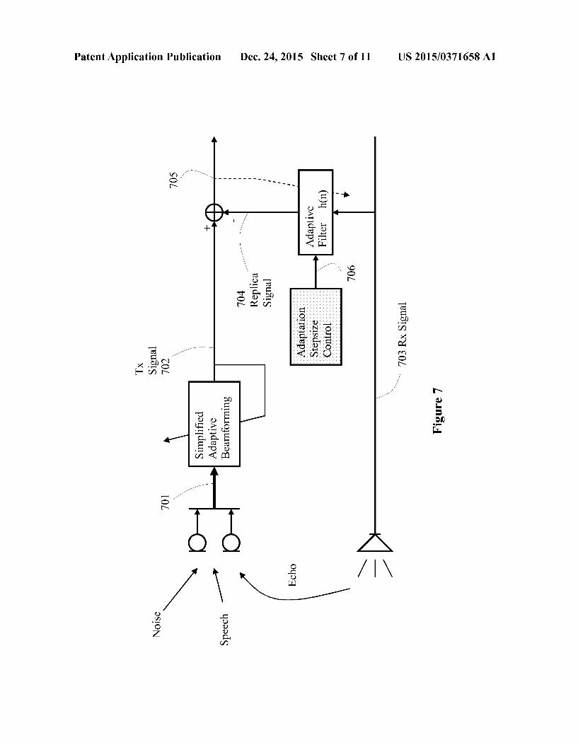
().IV-0.Id)
US 2015/0371658 A1 Dec. 24, 2015 Sheet 4 of 11 Patent Application Publication
08
09
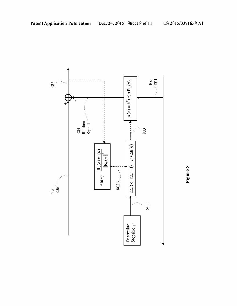
US 2015/0371658 A1 Dec. 24, 2015 Sheet 5 of 11 Patent Application Publication
08
09
S 9.InáH
US 2015/0371658 A1 Dec. 24, 2015 Sheet 6 of 11 Patent Application Publication
IbuñIS XXI Ç09 XL
| 09
?SION
US 2015/0371658 A1 Dec. 24, 2015 Sheet 7 of 11 Patent Application Publication
S0/
(u)? JOJIH QA?depV rDN QLVTE
Ieu?IS XXI ÇOL XL
L 0.InáH
/ q000dS ?SION
US 2015/0371658 A1 Dec. 24, 2015 Sheet 8 of 11 Patent Application Publication
()
8 9 InõIGI
(~ 908 XL
US 2015/0371658 A1 Dec. 24, 2015 Sheet 9 of 11 Patent Application Publication
906
| 06 IpuãIS
6 9.InáH
?seT O?OGI dooT-uòdO
Z06 IpuãIS | 06 IpuãIS XL
US 2015/0371658 A1 Dec. 24, 2015 Sheet 10 of 11 Patent Application Publication
US 2015/0371658 A1 Dec. 24, 2015 Sheet 11 of 11 Patent Application Publication
(HEILNTRICH /CTRIVO8HÅEIXI /EISÍTOWN AVTdISICI
@HOV HRHEILNI O/I ÅRHOVNIHWN
@HOV HRHEILNI XINHOAAL?HN
US 2015/0371658 A1
CONTROL OF ACOUSTC ECHO CANCELLERADAPTIVE FILTER FOR
SPEECHENHANCEMENT
0001. This application claims the benefit of U.S. Provi sional Application No. 62/014.359 filed on Jun. 19, 2014, entitled “Control of Acoustic Echo Canceller Adaptive Filter for Speech Enhancement.” U.S. Provisional Application No. 62/014,355 filed on Jun. 19, 2014, entitled “Energy Adjust ment of Acoustic Echo Replica Signal for Speech Enhance ment.” U.S. Provisional Application No. 62/014.346 filed on Jun. 19, 2014, entitled 'Acoustic Echo Preprocessing for Speech Enhancement.” U.S. Provisional Application No. 62/014.365 filed on Jun. 19, 2014, entitled “Post Ton Sup pression for Speech Enhancement, which application is hereby incorporated herein by reference.
TECHNICAL FIELD
0002 The present invention is generally in the field of Echo Cancellation/Speech Enhancement. In particular, the present invention is used to improve Acoustic Echo Cancel lation.
BACKGROUND
0003 For audio signal acquisition human/machine inter faces, especially in hands-free condition, adaptive beam forming microphone arrays have been widely employed for enhancing a desired signal while Suppressing interference and noise. For full-duplex communication systems, not only interference and noise corrupt the desired signal, but also acoustic echoes originating from loudspeakers. For Suppress ing acoustic echoes, acoustic echo cancellers (AECs) using adaptive filters may be the optimum choice since they exploit the reference information provided by the loudspeaker sig nals. 0004 To simultaneously suppress interferences and acoustic echoes, it is thus desirable to combine acoustic echo cancellation with adaptive beam forming in the acoustic human/machine interface. To achieve optimum performance, synergies between the AECs and the beam former should be exploited while the computational complexity should be kept moderate. When designing such a joint acoustic echo cancel lation and beam forming system, it proves necessary to con sider especially the time-variance of the acoustic echo path, the background noise level, and the reverberation time of the acoustic environment. To combine acoustic echo cancellation with beam forming, various strategies were studied in the public literatures, reaching from cascades of AECs and beam formers to integrated solutions. These combinations address aspects such as maximization of the echo and noise Suppres sion for slowly time-varying echo paths and high echo-to interference ratios (EIRs), strongly time-varying echo paths, and low EIRS, or minimization of the computational com plexity. 0005 For full-duplex hands-free acoustic human/machine interfaces, often a combination of acoustic echo cancellation and speech enhancement is required to suppress acoustic echoes, local interference, and noise. However, efficient solu tions for situations with high level background noise, with time-varying echo paths, with long echo reverberation time, and frequent double talk, are still a challenging research topic. To optimally exploit positive synergies between acous tic echo cancellation and speech enhancement, adaptive beam forming and acoustic echo cancellation may be jointly
Dec. 24, 2015
optimized. The adaptive beam forming system itself is already quite complex for most consumer oriented applications; the system of jointly optimizing the adaptive beam forming and the acoustic echo canceller could be too complex. 0006 An AEC first system or beam forming first system which has lower complexity than the system of jointly opti mizing the adaptive beam forming and the acoustic echo can celler. In the AEC first system, positive synergies for the adaptive beam forming can be exploited after convergence of the AECs: the acoustic echoes are efficiently suppressed by the AECs, and the adaptive beam former does not depend on the echo signals. One AEC is necessary for each microphone channel so that multiple complexity is required for multiple microphones at least for filtering and filter update in compari son to an AEC for a single microphone. Moreover, in the presence of strong interference and noise, the adaptation of AECs must be slowed down or even stopped in order to avoid instabilities of the adaptive filters. Alternatively, the AEC can be placed behind the adaptive beam former in the beam form ing first system; the complexity is reduced to that of AEC for a single microphone. However, positive synergies can not be exploited for the adaptive beam former since the beam former sees not only interferences but also acoustic echoes. 0007 Beamforming is a technique which extracts the desired signal contaminated by interference based on direc tivity, i.e., spatial signal selectivity. This extraction is per formed by processing the signals obtained by multiple sen sors such as microphones located at different positions in the space. The principle of beam forming has been known for a long time. Because of the vast amount of necessary signal processing, most research and development effort has been focused on geological investigations and Sonar, which can afford a high cost. With the advent of LSI technology, the required amount of signal processing has become relatively Small. As a result, a variety of research projects where acous tic beam forming is applied to consumer-oriented applications Such as cellular phone speech enhancement, have been car ried out. Applications of beam forming include microphone arrays for speech enhancement. The goal of speech enhance ment is to remove undesirable signals such as noise and reverberation. Amount research areas in the field of speech enhancement are teleconferencing, hands-free telephones, hearing aids, speech recognition, intelligibility improvement, and acoustic measurement.
0008. The signal played back by the loudspeaker is fed back to the microphones, where the signals appearas acoustic echoes. With the assumption that the amplifiers and the trans ducers are linear, a linear model is commonly used for the echo paths between the loudspeaker signal and the micro phone signals. To cancel the acoustic echoes in the micro phone channel, an adaptive filter is placed in parallel to the echo paths between the loudspeaker signal and the micro phone signal with the loudspeaker signal as a reference. The adaptive filter forms replicas of the echo paths such that the output signal of the adaptive filter are replicas of the acoustic echoes. Subtracting the output signal of the adaptive filter from the microphone signal thus Suppresses the acoustic ech oes. Acoustic echo cancellation is then a system identification problem, where the echo paths are usually identified by adap tive linear filtering. The design of the adaptation algorithm of the adaptive filter requires consideration of the nature of the echo paths and of the echo signals.
US 2015/0371658 A1
SUMMARY
0009. In accordance with an embodiment of the present invention, a method for cancelling/reducing acoustic echoes in speech/audio signal enhancement processing comprises using a received reference signal to excite an adaptive filter wherein the output of the adaptive filter forms a replica signal of acoustic echo; an adaptation step size for updating the coefficients of the adaptive filter is controlled by combining an open-loop approach and a closed-loop approach; one of the most important parameters with the open-loop approach is an energy ratio between an energy of a returned echo signal in an input microphone signal and an energy of the received reference signal; one of the most important parameters with the closed-loop approach is a normalized correlation or a square of the normalized correlation between the input micro phone signal and the replica signal of acoustic echo; the replica signal of acoustic echo is Subtracted from the micro phone input signal to Suppress the acoustic echo in the micro phone input signal. 0010. In accordance with an alternative embodiment of the present invention, a method for cancelling/reducing acoustic echoes in speech/audio signal enhancement processing com prises using a received reference signal to excite an adaptive filter wherein the output of the adaptive filter forms a replica signal of acoustic echo; an adaptation step size is controlled for updating the coefficients of the adaptive filter; the adap tation step size is initialized by using an open-loop approach and optimized by using a closed-loop approach; one of the most important parameters with the open-loop approach is an energy ratio between an energy of a returned echo signal in an input microphone signal and an energy of the received refer ence signal; one of the most important parameters with the closed-loop approach is a normalized correlation or a square of the normalized correlation between the input microphone signal and the replica signal of acoustic echo; the replica signal of acoustic echo is Subtracted from the microphone input signal to Suppress the acoustic echo in the microphone input signal. 0011. In an alternative embodiment, a speech signal enhancement processing apparatus comprises a processor, and a computer readable storage medium storing program ming for execution by the processor. The programming include instructions to use a received reference signal to excite an adaptive filter wherein the output of the adaptive filter forms a replica signal of acoustic echo; an adaptation step size for updating the coefficients of the adaptive filter is controlled by combining an open-loop approach and a closed loop approach; one of the most important parameters with the open-loop approach is an energy ratio between an energy of a returned echo signal in an input microphone signal and an energy of the received reference signal; one of the most important parameters with the closed-loop approach is a nor malized correlation or a square of the normalized correlation between the input microphone signal and the replica signal of acoustic echo; the replica signal of acoustic echo is Subtracted from the microphone input signal to Suppress the acoustic echo in the microphone input signal.
BRIEF DESCRIPTION OF THE DRAWINGS
0012 For a more complete understanding of the present invention, and the advantages thereof, reference is now made to the following descriptions taken in conjunction with the accompanying drawings, in which:
Dec. 24, 2015
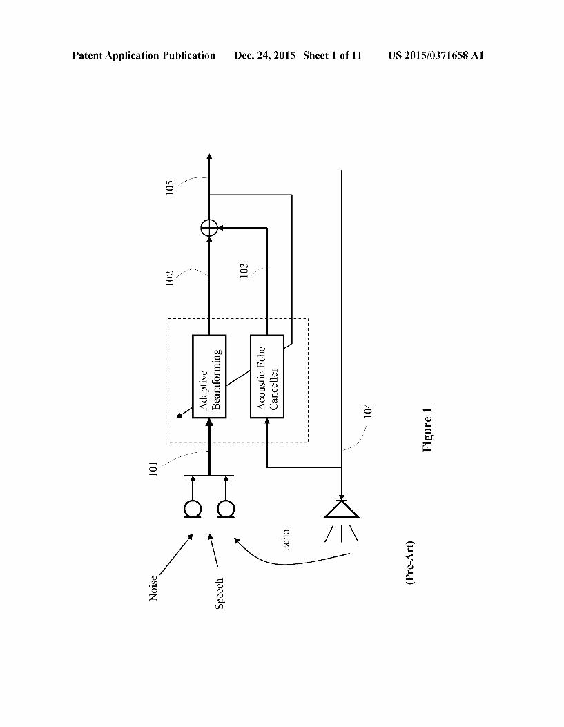
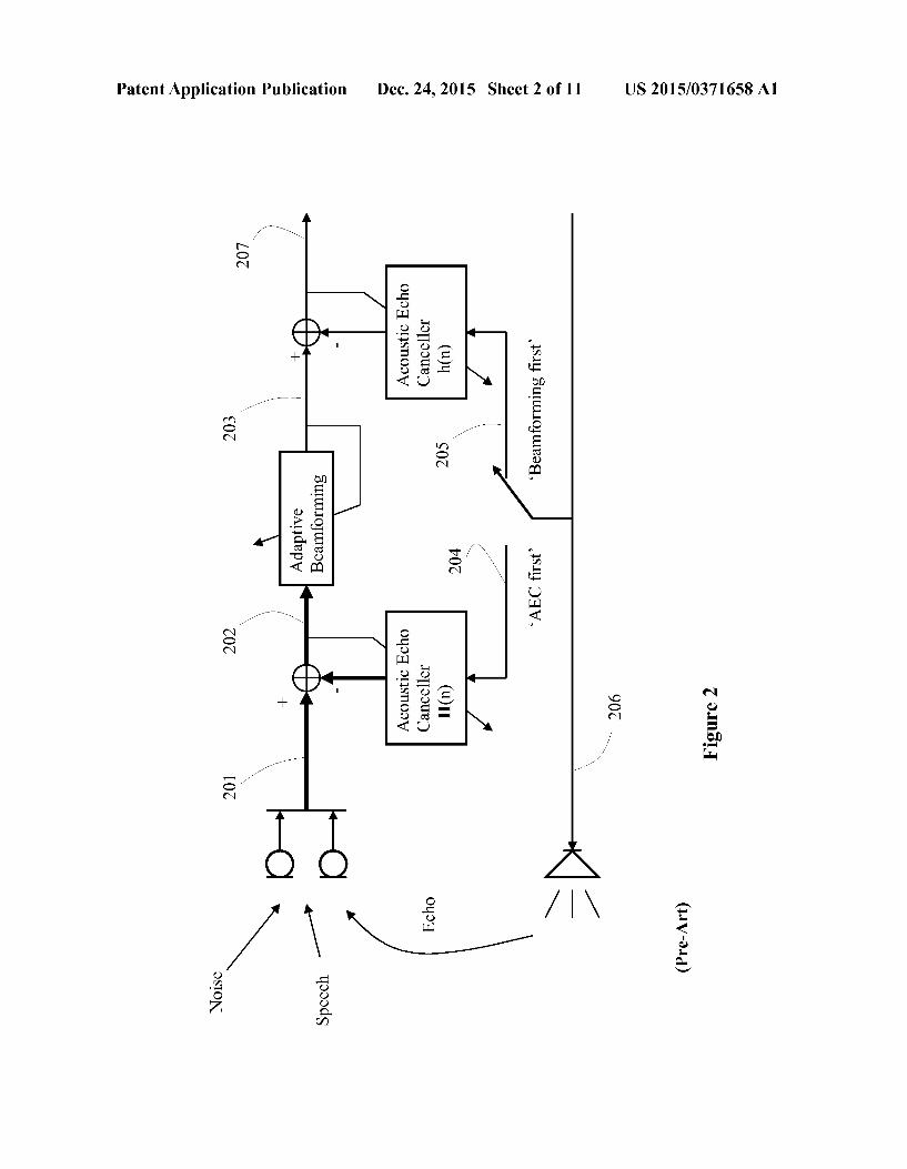
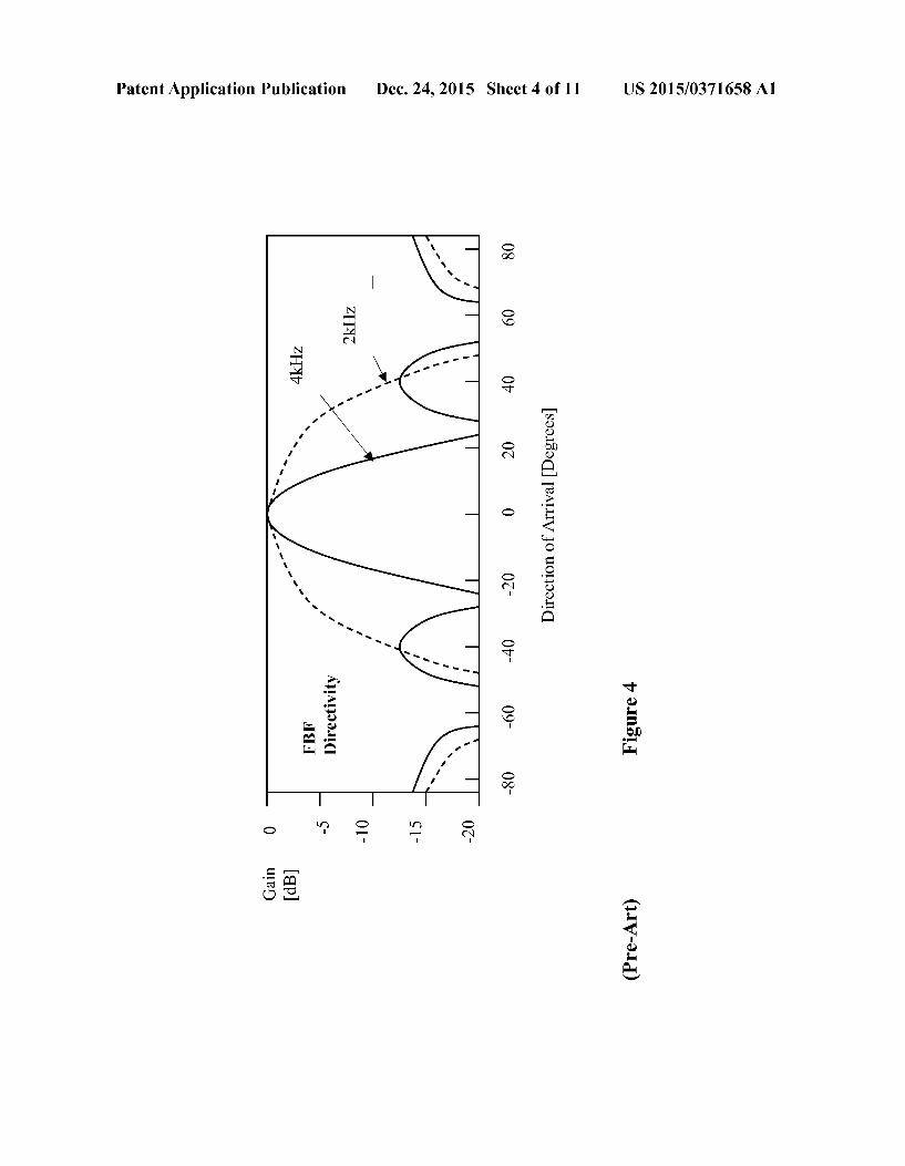
0013 FIG. 1 illustrates a joint optimization of Adaptive Beamforming and Acoustic Echo Cancellation (AEC). 0014 FIG. 2 illustrates a combination of AEC and Beam forming. 0015 FIG. 3 illustrates a traditional Beamformer/Noise Canceller. (0016 FIG. 4 illustrates a directivity of Fixed Beamformer. (0017 FIG. 5 illustrates a directivity of Block Matrix. 0018 FIG. 6 illustrates an traditional AEC system. (0019 FIG. 7 illustrates an AEC with adaptation step size control of adaptive filter. 0020 FIG. 8 illustrates an adaptive filter with adaptation step size control. 0021 FIG. 9 illustrates a step size determination algo rithm for AEC adaptive filter. 0022 FIG. 10 illustrates a communication system accord ing to an embodiment of the present invention. 0023 FIG. 11 illustrates a block diagram of a processing system that may be used for implementing the devices and methods disclosed herein.
DETAILED DESCRIPTION OF ILLUSTRATIVE EMBODIMENTS
0024. To optimally exploit positive synergies between acoustic echo cancellation and speech enhancement, adaptive beam forming and acoustic echo cancellation may be jointly optimized as shown in FIG.1. 101 are input signals from an array of microphones; 102 is a noise reduced signal output from adaptive beam forming system; the signal 104 outputs to the speaker, which is used as a reference signal of the echo canceller to produce an echo replica signal 103; the signal 102 and the signal 103 are combined to produce an optimal output signal 105 by jointly optimizing the adaptive beam forming and the acoustic echo canceller. The adaptive beam forming system itself is already quite complex for most consumer oriented applications; the FIG. 1 system of jointly optimizing the adaptive beam forming and the acoustic echo canceller could be too complex, although the FIG. 1 system can theo retically show its advantage for high levels of background noise, time-varying echo paths, long echo reverberation time, and frequent double talk. (0025 FIG. 2 shows an AEC first system or beam form ing first system which has lower complexity than the system of FIG. 1. In the AEC first system, a matrix H(n) directly models the echo paths between the speaker and all micro phones without interaction with the adaptive beam forming. For the adaptive beam forming, positive synergies can be exploited after convergence of the AECs: the acoustic echoes are efficiently suppressed by the AECs, and the adaptive beam former does not depend on the echo signals. One AEC is necessary for each microphone channel so that multiple com plexity is required for multiple microphones at least for fil tering and filter update in comparison to an AEC for a single microphone. Moreover, in the presence of strong interference and noise, the adaptation of AECs must be slowed down or even stopped in order to avoid instabilities of the adaptive filters H(n). Alternatively, the AEC can be placed behind the adaptive beam former in the beam forming first system; the complexity is reduced to that of AEC for a single microphone. However, positive synergies cannot be exploited for the adap tive beam former since the beam formersees not only interfer ences but also acoustic echoes. 201 are input signals from an array of microphones; for the AEC first system, echoes in each component signal of 201 need to be suppressed to get an
US 2015/0371658 A1
array of signals 202 inputting to the adaptive beam forming system; the speaker output signal 206 is used as a reference signal 204 of echo cancellation for the AEC first system or as a reference signal 205 of echo cancellation for the beam forming first system. In the beam forming first system, ech oes only in one signal 203 output from the adaptive beam forming system need to be cancelled to get final output signal 207 in which both echoes and background noise have been Suppressed or reduced. As the single adaptation of the echo canceller response h(n) in the beam forming first system has much lower complexity than the matrix adaptation of the echo canceller response H(n) in the AEC first system, obviously the beam forming first system has lower complexity than the AEC first system. 0026 Beamforming can be considered as multi-dimen sional signal processing in space and time. Ideal conditions assumed in most theoretical discussions are not always main tained. The target DOA (direction of arrival), which is assumed to be stable, does change with the movement of the speaker. The sensor gains, which are assumed uniform, exhibit significant distribution. As a result, the performance obtained by beam forming may not be as good as expected. Therefore, robustness against steering-vector errors caused by these array imperfections are become more and more important. 0027. A beam former which adaptively forms its directiv
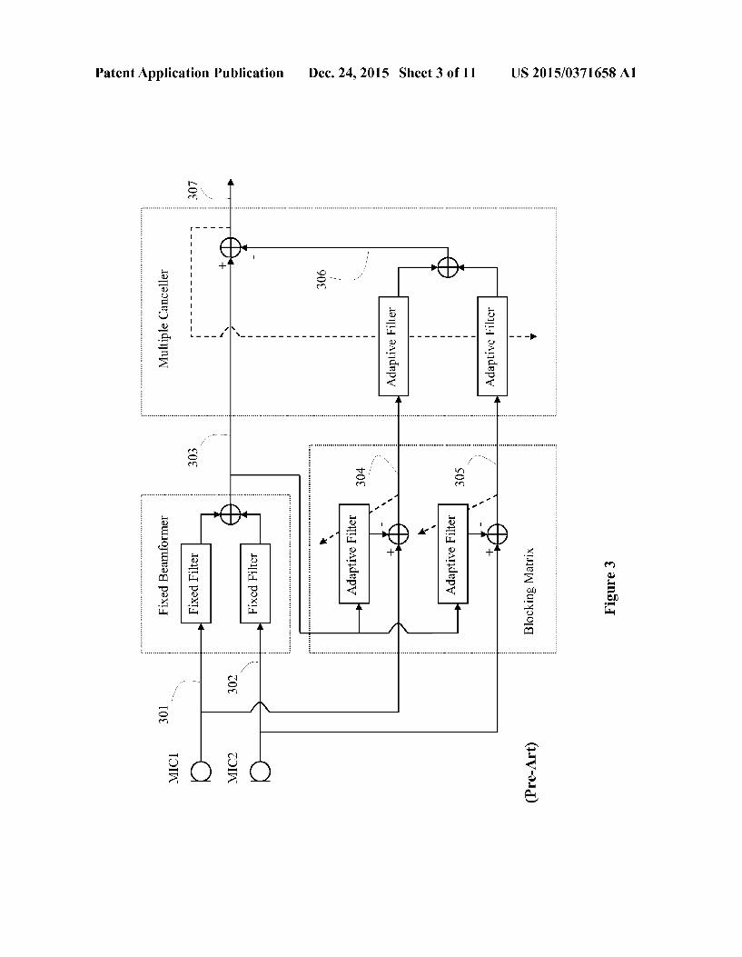
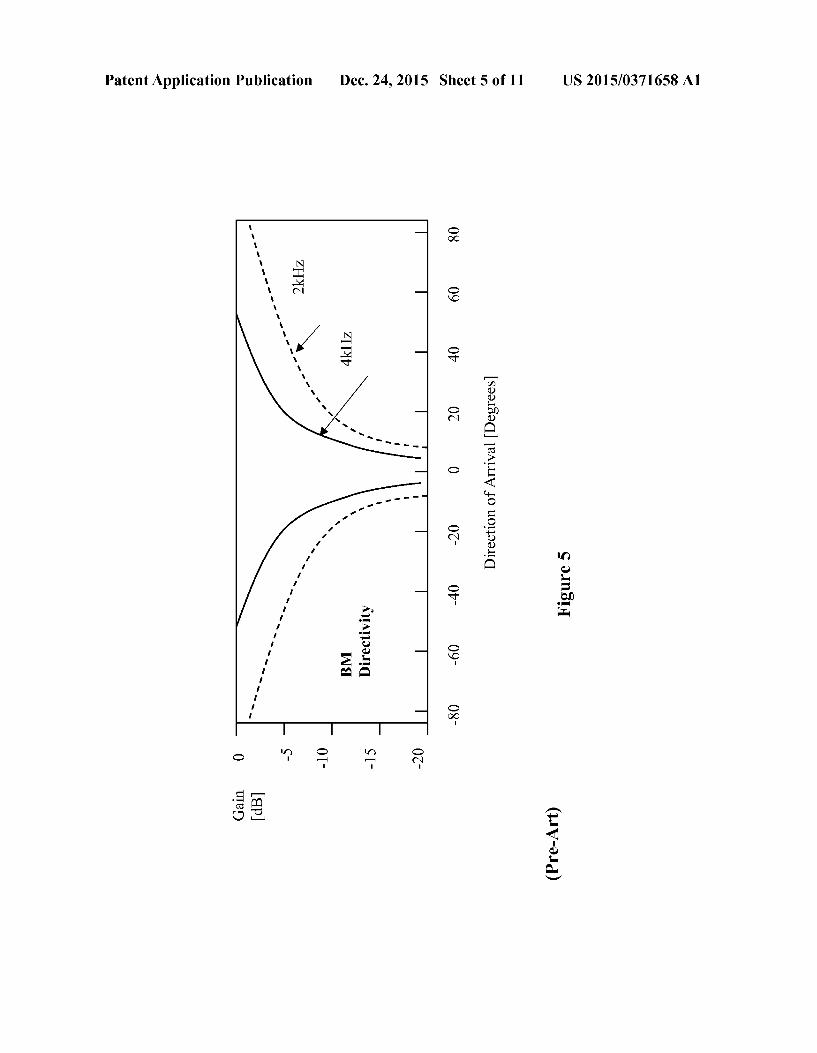
ity pattern is called an adaptive beam former. It simulta neously performs beam steering and null steering. In most traditional acoustic beam formers, however, only null steering is performed with an assumption that the target DOA is known a priori. Due to adaptive processing, deep nulls can be developed. Adaptive beam formers naturally exhibit higher interference Suppression capability than its fixed counterpart. FIG.3 depicts a structure of a widely known adaptive beam former among various adaptive beam formers. Microphone array could contain multiple microphones; for the simplicity, FIG.3 only shows two microphones. 0028 FIG.3 comprises a fixed beam former (FBF), a mul tiple input canceller (MC), and blocking matrix (BM). The FBF is designed to form a beam in the look direction so that the target signal is passed and all other signals are attenuated. On the contrary, the BM forms a null in the look direction so that the target signal is Suppressed and all other signals are passed through. The inputs 301 and 302 of FBF are signals coming from MICs. 303 is the output target signal of FBF. 301, 302 and 303 are also used as inputs of BM. The MC is composed of multiple adaptive filters each of which is driven by a BMoutput. The BMoutputs 304 and 305 contain all the signal components except that in the look direction. Based on these signals, the adaptive filters generate replicas 306 of components correlated with the interferences. All the replicas are subtracted from a delayed output signal of the fixed beam former which has an enhanced target signal component. In the subtracted output 307, the target signal is enhanced and unde sirable signals such as ambient noise and interferences are suppressed. FIG. 4. shows an example of directivity of the FBF. FIG. 5. shows an example of directivity of the BM. In real applications, the system FIG. 3 can be simplified and made more efficient, the details of which are out of scope of this specification and will not be discussed here.
Dec. 24, 2015
0029. The acoustic echo paths may vary strongly over time due to moving sources or changes in the acoustic environment requiring a good tracking performance of the adaptationalgo rithm. The reverberation time of the acoustic environment typically ranges from, e.g., TsS0 ms in passenger cabins of vehicles to T-1 s in public halls. With the theoretical length estimation of the adaptive filter order N
ERLE his go
where ERLE is the desired echo suppression of the AEC in dB; as a rule of thumb it becomes obvious that with many realistic acoustic environment and sampling rates f 4-48 kHz, adaptive FIR filters with several thousands coefficients are needed to achieve ERLE-20 dB. Obviously, too long adaptive filter order is not practical not only in the sense of the complexity but also of the convergence time. For environ ments with long reverberation times, this means that the time for convergence—even for fast converging adaptation algo rithms—cannot be neglected and that, after a change of echo paths, noticeable residual echoes may be present until the adaptation algorithm is re-converged. 0030. As mentioned above, the echo reverberation time mainly depends on the location of the loudspeaker and the microphones, ranging from, e.g., TsS0 ms in passenger cab ins of vehicles to T1 s in public halls. When the case of long echo reverberation time happens, one way to keep the effi ciency of the echo cancellation is to increase the order of the adaptive filter; however, this may not be realistic because of two reasons: (1) too high order of the adaptive filter causes too high complexity; (2) too high order of the adaptive filter causes too slow adaptation convergence of the adaptive filter. That is why a common order of the adaptive filter is about few hundreds for a sampling rate of 8000 Hz. 0031. The presence of disturbing sources such as desired speech, interference, or ambient noise may lead to instability and divergence of the adaptive filter. To prevent the instability, adaptation control mechanisms are required which adjust the stepsize of the adaptation algorithm to the present acoustic conditions. With a decrease in the power ratio of acoustic echoes and disturbance, a smaller stepsize becomes manda tory, which however increases the time until the adaptive filter have converged to efficient echo path models. As the above discussion about adaptive filtering for acoustic echo cancel lation shows, the convergence time of the adaptive filter is a crucial factor in acoustic echo cancellation and limits the performance of AECs in realistic acoustic environments. With the aim of reducing the convergence time while assuring robustness against instabilities and divergence even during double talk, Various adaptation algorithms have been Studied in public literatures and articles for realizations in the time domain and or in the frequency domain. 0032 Even with fast converging adaptation algorithms, there are typically residual echoes present at the output of the AEC. Furthermore, it is desirable to combine the echo can cellation with noise reduction. Therefore, post echo and noise reduction is often cascaded with the AEC to suppress the residual echoes and noise at the AEC output. These methods are typically based on spectral subtraction or Wiener filtering so that estimates of the noise spectrum and of the spectrum of the acoustic echoes at the AEC output are required. These are
US 2015/0371658 A1
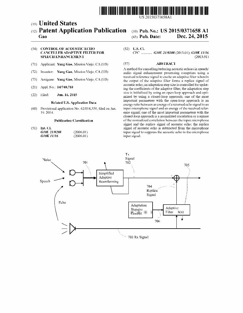
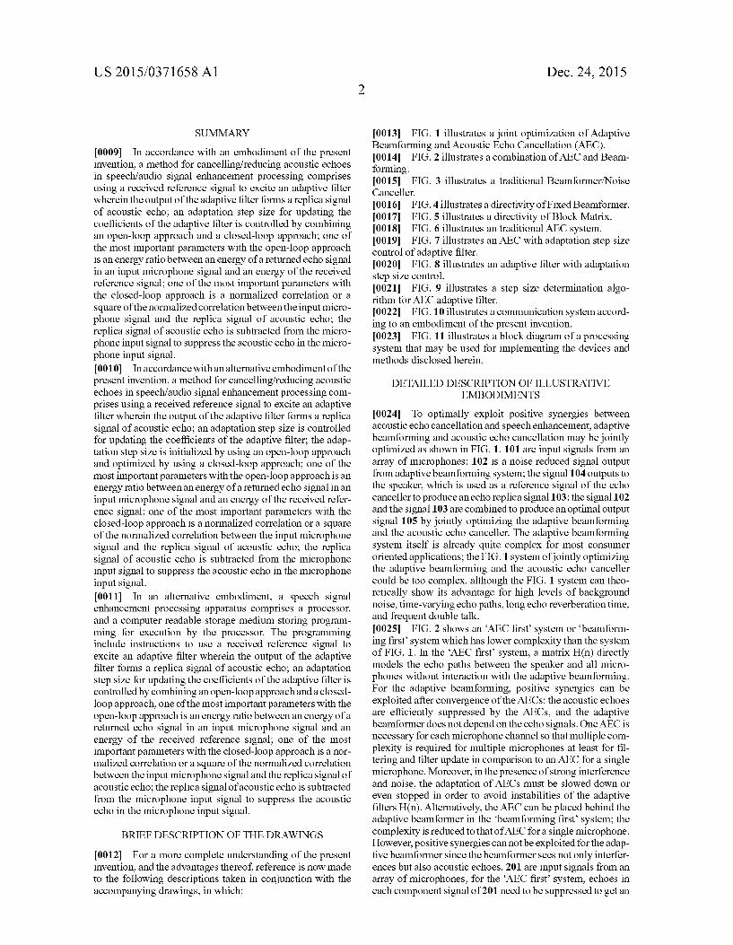
often difficult to obtain in a single-microphone system for time-varying noise spectra and frequently changing echo paths. 0033 FIG. 6 shows a traditional basic structure of AEC with a simplified beam forming system. To limit the compu tational complexity, beam forming first system is adopted. The microphone array signals 601 are processed first by the simplified adaptive beam former to get a single noise-reduced Tx signal 602; RX signal 603 is employed as an excitation signal for the adaptive filter to produce an echo replica signal 604; the echo-suppressed signal 605 is obtained by subtract ing the echo replica signal 604 from the Tx signal 602. 0034 FIG. 7 shows the similar structure as FIG. 6 except a block of Adaptation-Stepsize-Control is added to efficiently produce a stepsize parameter 706 and control the adaptation of the adaptive filter. To limit the computational complexity, beam forming first system is also adopted. The microphone array signals 701 are processed first by the simplified adaptive beam former to get a single noise-reduced Tx signal 702; RX signal 703 is employed as an excitation signal for the adaptive filter to produce an echo replica signal 704; the echo-sup pressed signal 705 is obtained by subtracting the echo replica signal 704 from the Tx signal 702. 0035. In the FIG. 7 system, the Adaptation-Stepsize-Con
trol is an important diagram block. The performance of the adaptive filter highly depends on the quality of the estimated stepsize parameter 706. This is specially true in an environ ment of echo path change, double talk, and/or unstable noise. In order to have a nice output 705 of the AEC, the echoes in the Tx signal 702 need to be cancelled; this is achieved by producing a replica signal 704 matching the echo component in the input signal 702. In general, the smaller is the difference between the echo component in the input signal 702 and the replica signal 704 from the adaptive filter, the better quality has the output signal 705. The adaptive filter is an FIR filter, the impulsive response of which is theoretically adapted in such way that the difference between the echo component in 702 and the replica signal 704 is minimized. In realty, the exact echo component in 702 is not known; instead, the adap tation algorithm of the adaptive filter impulsive response is conducted by minimizing the difference between the 702 signal and the 704 signal in echo areas; we can imagine that emphasizing the filter adaptation in high echo energy areas may achieve better quality than low echo energy areas. The goal of the controlling of the adaptive filter is to minimize the leakage of echo component into the output signal 705. 0036. The impulsive response of the adaptive filter of AEC can be expressed as,
wherein N is the filter order, the subscriptie 0,1,2,...,N-1} addresses the ith coefficient of the impulsive response of the adaptive filter at the time index n. In general, a normalized least mean Square algorithm leads to the impulsive response h(n) updated at each time index n in the areas where echoes exist:
wherein Ah(n) is the maximum update portion and L, Osus1, is the stepsize which controls the update amount at each time
Dec. 24, 2015
index. Suppose a vecotor of the RX signal 703 is noted as R(n), the TX signal 702 is noted as T(n), the replica signal 704 is noted as d(n), and the difference signal 705 is noted as e(n); the maximum update portion can be expressed as a Vector:
R(n). e(n) (3) Ah(n) = () role
wherein R(n) is the vector of the signal 703 with a length N and
e(n)=T(n)-d(n) (4)
d(n)=h(n)-R(n) (5)
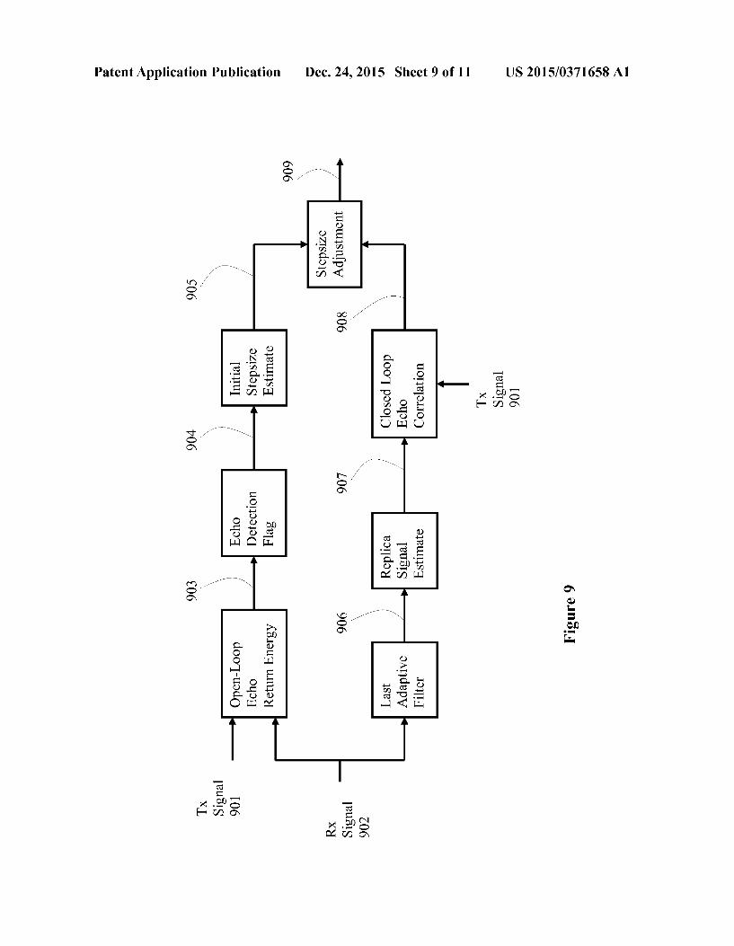
0037. The key factor for the performance of the adaptive filter is the determination of the stepsizeu, Osus 1. As the goal is to cancel echo component, in non-echo areas the stepsize L is set to zero and the adaptive filter is not updated. In echo areas, an appropriate stepsize L value should be set; usually, the stepsize L should be high in high echo areas and low in low echo areas. Too low stepsize L could cause too slow conven gence speed of the adaptive filter so that some echo portion may not be cancelled; too high stepsize L could possibly cause unstable adaptive filter or cancelling needed signal portion. 0038 FIG. 8 shows a mathematical procedure of the adap tive filter. The maximum stepsize vector 802 is the error signal e(n) 807 normalized by the reference input signal RX 801. After determining the stepsize 805, an adaptive filter coeffi cient vector 803 is updated. An echo replica signal 804 is produced by passing the RX signal 801 through the updated adaptive filter. An echo-reduced signal 807 is finally obtained by subtracting the replica signal 804 from the Tx signal 806. 0039 FIG. 9 shows a more detailed procedure to deter mining the stepsize by employing parameters from both open-loop approach and closed-loop approach. The param eters 903 of open-loop echo return energy are obtained by analyzing and comparing the TX signal 901 and RX signal 902. An echo detection flag 904 is decided according to the parameters of open-loop echo return energy. The initial step size 905 based on the open-loop approach is set in the detected echo areas. A closed-loop approach will further improve and correct the initial stepsize 905. As the current stepsize should be determined before the current adaptive filter is updated, the current adaptive filter is not known yet during the determination of the current stepsize; therefore, the last adaptive filter 906 is used to filter the RX signal 902 and estimate an echo replica signal 907. A closed-loop echo cor relation 908 between the estimated replica signal 907 and the Tx signal 901 is calculated, which will be used to improve and correct the initial stepsize and get the final stepsize 909. 0040. The following is a detailed example of determining the stepsize. Some symbols for open-loop parameters are first defined:
0041 Echoloss0: Tx signal 901 energy in dB minus RX signal 902 energy in dB at the same time frame;
0.042 0.043 Echoloss sm: moving average value of Echo Loss 1 in lowest value areas of EchoLoss 1:
0044. DiffBchoLoss0=EchoLoss0-EchoLoss sm; 0045. DiffBchoLoss1=EchoLoss1-EchoLoss sm;
Echolossl: moving average value of Echo Loss0;
US 2015/0371658 A1
0046 Echoloss0 HF: Tx signal 901 high frequency energy in dB minus RX signal 902 high frequency energy in dB at the same time frame;
0047 Echoloss 1 HF: moving average value of Echo Loss0 HF:
0048 Echoloss HF sm: moving average value of EchoLoss 1 HF in lowest value areas of EchoLoss 1 HF:
0049. DiffchoLoss0 HF=EchoLoss0 HF-Echo LOSS HF Sm;
0050 EchoFlags=1 means echoes detected; otherwise not detected.
0051. The open-loop echo detection flag 904 is deter mined like this:
EchoFlag=0; if ( (DiffEcho LossO<6 OR DiffEchoLossO HF-6) AND (DiffEchoLoss1<6)) {
EchoFlag=1:
if ( (DiffEcho LossO<5 OR DiffEchoLossO HF-5) AND (DiffEcho Loss1<5) ) {
EchoFlag=2;
if ( (DiffEcho LossO<2) AND (DiffEcho Loss1<2)) {
EchoFlag=3;
0052 Some symbols for closed-loop parameters are defined here:
0053 Corr RXTX: square of the normalized correlation between the estimated echo replica signal 907 and the TX signal 901;
0054 Corr RxTx sm: smoothed Corr RxTx: 0055 Corr RxTx LF: square of the normalized corre lation between the low-pass of the estimated echo rep lica signal 907 and the low-pass of the Tx signal 901;
0056 Corr RxTx LF sm: smoothed Corr RxTx LF: 0057 VAD RX=0 means noise areas in RX signal; oth erwise non noise areas in RX signal;
0.058 Stepsize: controlling parameter between 0 and 1. In more detail, the square of the normalized correlation between the echo replica RX signal and the TX signal is
2. Tx(n). Rio Corr RXTX = . . . . . . . . . .
|E Tr(n)? Rx(n)? when X. Tx(n). Rx(n) > 0
= 0, when X. Tx(n). Rx(n) < 0
0059 An example way to determine the stepsize by using and combining both open-loop parameters and closed-loop parameters is following:
Initial with open-loop parameters: Stepsize = EchoFlag 0.2:
Improving and correcting with closed-loop parameters: sqr corr min = MINK Corr RxTx, Corr RxTx LF : sqr corr = MAX{sqr corr min-O.25,0} f 0.75; sqr corr = sqr corr *MIN{2* Corr RxTx Sm, 1};
Dec. 24, 2015
-continued
Stepsize = MAX: Stepsize, 0.5* sqr corr: Sqr corr = Sqr corr min - MIN{Corr RxTx LF, Corr RxTx LF sm: sqr corr = MIN{MAX{2*sqr corr, 0, 1}; sqr corr = sqr corr *MIN{2* Corr RxTx LFsm, 1}; if (VAD Rx=0) {
sqr corr = 0;
Stepsize = MAX: Stepsize, 0.5 * sqr corr.
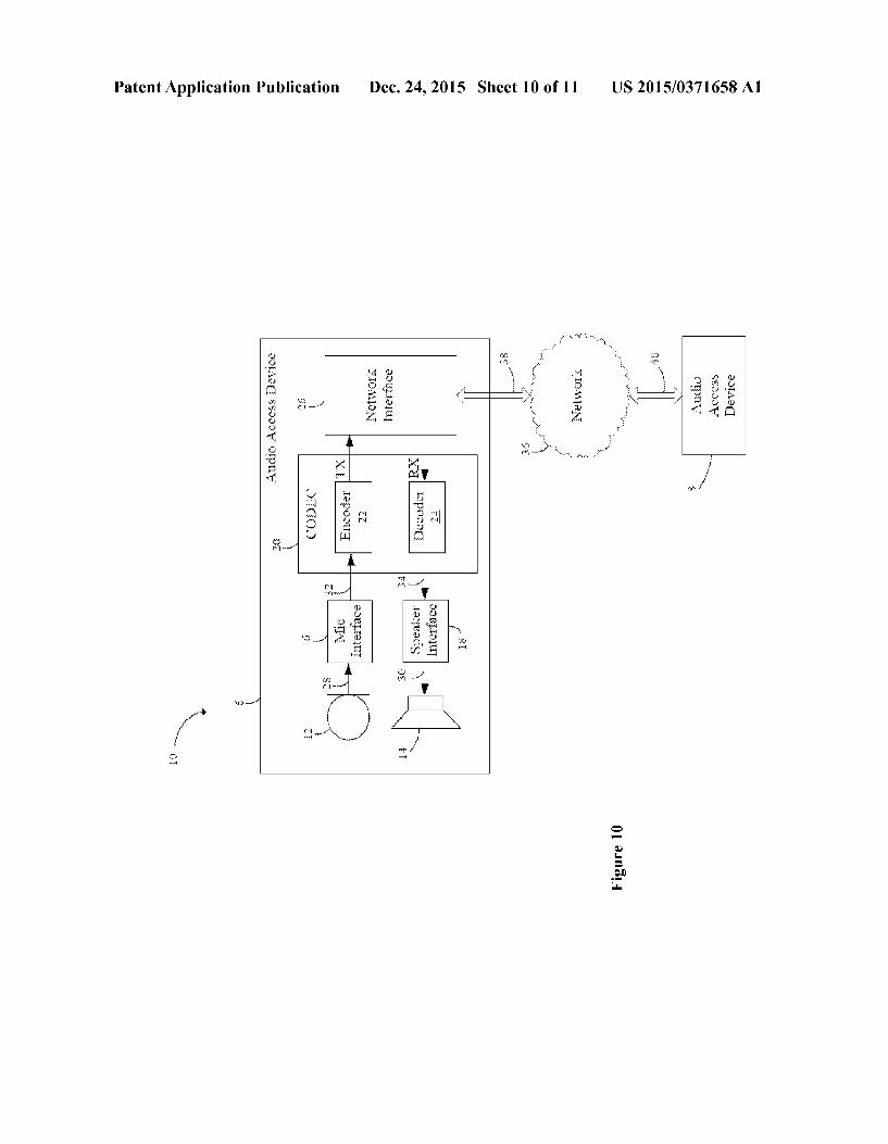
0060 FIG. 10 illustrates a communication system 10 according to an embodiment of the present invention. Com munication system 10 has audio access devices 7 and 8 coupled to a network 36 via communication links 38 and 40. In one embodiment, audio access device 7 and 8 are voice over internet protocol (VOIP) devices and network 36 is a wide area network (WAN), public switched telephone net work (PTSN) and/or the internet. In another embodiment, communication links 38 and 40 are wireline and/or wireless broadband connections. In an alternative embodiment, audio access devices 7 and 8 are cellular or mobile telephones, links 38 and 40 are wireless mobile telephone channels and net work 36 represents a mobile telephone network. 0061 The audio access device 7 uses a microphone 12 to convert Sound, such as music or a person's voice into an analog audio input signal 28. A microphone interface 16 converts the analog audio input signal 28 into a digital audio signal 33 for input into an encoder 22 of a CODEC 20. The encoder 22 can include a speech enhancement block which reduces noise/interferences in the input signal from the microphone(s). The encoder 22 produces encoded audio sig nal TX for transmission to a network 26 via a network inter face 26 according to embodiments of the present invention. A decoder 24 within the CODEC 20 receives encoded audio signal RX from the network 36 via network interface 26, and converts encoded audio signal RX into a digital audio signal 34. The speaker interface 18 converts the digital audio signal 34 into the audio signal 30 suitable for driving the loud speaker 14. 0062. In embodiments of the present invention, where audio access device 7 is a VOIP device, some or all of the components within audio access device 7 are implemented within a handset. In some embodiments, however, micro phone 12 and loudspeaker 14 are separate units, and micro phone interface 16, speaker interface 18, CODEC 20 and network interface 26 are implemented within a personal com puter. CODEC 20 can be implemented in either software running on a computer or a dedicated processor, or by dedi cated hardware, for example, on an application specific inte grated circuit (ASIC). Microphone interface 16 is imple mented by an analog-to-digital (A/D) converter, as well as other interface circuitry located within the handset and/or within the computer. Likewise, speaker interface 18 is imple mented by a digital-to-analog converter and other interface circuitry located within the handset and/or within the com puter. In further embodiments, audio access device 7 can be implemented and partitioned in other ways known in the art. 0063. In embodiments of the present invention where audio access device 7 is a cellular or mobile telephone, the elements within audio access device 7 are implemented within a cellular handset. CODEC 20 is implemented by Software running on a processor within the handset or by
US 2015/0371658 A1
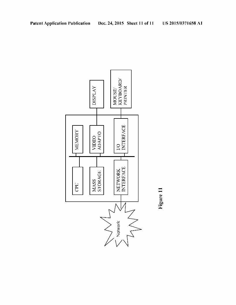
dedicated hardware. In further embodiments of the present invention, audio access device may be implemented in other devices such as peer-to-peer wireline and wireless digital communication systems, such as intercoms, and radio hand sets. In applications such as consumer audio devices, audio access device may contain a CODEC with only encoder 22 or decoder 24, for example, in a digital microphone system or music playback device. In other embodiments of the present invention, CODEC 20 can be used without microphone 12 and speaker 14, for example, in cellular base stations that access the PTSN. 0064. The speech processing for reducing noise/interfer ence described in various embodiments of the present inven tion may be implemented in the encoder 22 or the decoder 24, for example. The speech processing for reducing noise/inter ference may be implemented in hardware or software in vari ous embodiments. For example, the encoder 22 or the decoder 24 may be part of a digital signal processing (DSP) chip. 0065 FIG. 11 illustrates a block diagram of a processing system that may be used for implementing the devices and methods disclosed herein. Specific devices may utilize all of the components shown, or only a Subset of the components, and levels of integration may vary from device to device. Furthermore, a device may contain multiple instances of a component, such as multiple processing units, processors, memories, transmitters, receivers, etc. The processing system may comprise a processing unit equipped with one or more input/output devices, such as a speaker, microphone, mouse, touchscreen, keypad, keyboard, printer, display, and the like. The processing unit may include a central processing unit (CPU), memory, a mass storage device, a video adapter, and an I/O interface connected to a bus. 0066. The bus may be one or more of any type of several bus architectures including a memory bus or memory con troller, a peripheral bus, video bus, or the like. The CPU may comprise any type of electronic data processor. The memory may comprise any type of system memory such as static random access memory (SRAM), dynamic random access memory (DRAM), synchronous DRAM (SDRAM), read only memory (ROM), a combination thereof, or the like. In an embodiment, the memory may include ROM for use at boot up, and DRAM for program and data storage for use while executing programs. 0067. The mass storage device may comprise any type of storage device configured to store data, programs, and other information and to make the data, programs, and other infor mation accessible via the bus. The mass storage device may comprise, for example, one or more of a solid state drive, hard disk drive, a magnetic disk drive, an optical disk drive, or the like. 0068. The video adapter and the I/O interface provide interfaces to couple external input and output devices to the processing unit. As illustrated, examples of input and output devices include the display coupled to the video adapter and the mouse/keyboard/printer coupled to the I/O interface. Other devices may be coupled to the processing unit, and additional or fewer interface cards may be utilized. For example, a serial interface such as Universal Serial Bus (USB) (not shown) may be used to provide an interface for a printer. 0069. The processing unit also includes one or more net work interfaces, which may comprise wired links, such as an Ethernet cable or the like, and/or wireless links to access nodes or different networks. The network interface allows the
Dec. 24, 2015
processing unit to communicate with remote units via the networks. For example, the network interface may provide wireless communication via one or more transmitters/trans mit antennas and one or more receivers/receive antennas. In an embodiment, the processing unit is coupled to a local-area network or a wide-area network for data processing and com munications with remote devices, such as other processing units, the Internet, remote storage facilities, or the like. 0070 While this invention has been described with refer ence to illustrative embodiments, this description is not intended to be construed in a limiting sense. Various modifi cations and combinations of the illustrative embodiments, as well as other embodiments of the invention, will be apparent to persons skilled in the art upon reference to the description. For example, various embodiments described above may be combined with each other. 0071 Although the present invention and its advantages have been described in detail, it should be understood that various changes, Substitutions and alterations can be made herein without departing from the spirit and scope of the invention as defined by the appended claims. For example, many of the features and functions discussed above can be implemented in Software, hardware, or firmware, or a com bination thereof. Moreover, the scope of the present applica tion is not intended to be limited to the particular embodi ments of the process, machine, manufacture, composition of matter, means, methods and steps described in the specifica tion. As one of ordinary skill in the art will readily appreciate from the disclosure of the present invention, processes, machines, manufacture, compositions of matter, means, methods, or steps, presently existing or later to be developed, that perform substantially the same function or achieve sub stantially the same result as the corresponding embodiments described herein may be utilized according to the present invention. Accordingly, the appended claims are intended to include within their scope Such processes, machines, manu facture, compositions of matter, means, methods, or steps. What is claimed is: 1. A method for cancelling/reducing acoustic echoes in
speech/audio signal enhancement processing, the method comprising:
using a received reference signal to excite an adaptive filter wherein the output of the adaptive filter forms a replica signal of acoustic echo;
controlling an adaptation step size for updating the coeffi cients of the adaptive filter by combining an open-loop approach and a closed-loop approach, wherein one of the most important parameters with the open-loop approach is an energy ratio between an energy of a returned echo signal in an input microphone signal and an energy of the received reference signal, and one of the most important parameters with the closed-loop approach is a normalized correlation or a square of the normalized correlation between the input microphone signal and the replica signal of acoustic echo;
Subtracting the replica signal of acoustic echo from the microphone input signal to suppress the acoustic echo in the microphone input signal.
2. The method of claim 1, wherein cancelling/reducing acoustic echoes may happen after cancelling/reducing dis turbing noises.
3. The method of claim 1, wherein cancelling/reducing acoustic echoes may happen before cancelling/reducing dis turbing noises.
US 2015/0371658 A1
4. The method of claim 1, wherein the coefficients of the adaptive filter are updated in echo signal area.
5. The method of claim 1, wherein the energy ratio is the input microphone signal energy in dB minus the received reference signal energy in dB at the same time frame.
6. The method of claim 1, wherein the square of the nor malized correlation between the input microphone signal and the replica signal of acoustic echo is
2. Tx(n). Roof when X. Tx(n). Rx(n) > 0
= 0, when X. Tx(n). Rx(n) < 0
wherein TX(n) is the input microphone signal and RX(n) is the replica signal of acoustic echo.
7. The method of claim 1, wherein the square of the nor malized correlation is based on the input microphone signal and the replica signal of acoustic echo which is produced by the adaptive filter with the last updated filter coefficients.
8. A speech signal processing apparatus comprising: a processor; and a computer readable storage medium storing programming
for execution by the processor, the programming includ ing instructions to:
use a received reference signal to excite an adaptive filter wherein the output of the adaptive filter forms a replica signal of acoustic echo;
control an adaptation step size for updating the coefficients of the adaptive filter by combining an open-loop approach and a closed-loop approach, wherein one of the most important parameters with the open-loop approach is an energy ratio between an energy of a returned echo signal in an input microphone signal and an energy of the received reference signal, and one of the most important parameters with the closed-loop approach is a normalized correlation or a square of the normalized correlation between the input microphone signal and the replica signal of acoustic echo;
Subtract the replica signal of acoustic echo from the micro phone input signal to Suppress the acoustic echo in the microphone input signal.
9. The method of claim 8, wherein cancelling/reducing acoustic echoes may happen after cancelling/reducing dis turbing noises.
10. The method of claim 8, wherein cancelling/reducing acoustic echoes may happen before cancelling/reducing dis turbing noises.
11. The method of claim 8, wherein the coefficients of the adaptive filter are updated in echo signal area.
12. The method of claim 8, wherein the energy ratio is the input microphone signal energy in dB minus the received reference signal energy in dB at the same time frame.
13. The method of claim 8, wherein the square of the normalized correlation between the input microphone signal and the replica signal of acoustic echo is
Dec. 24, 2015
2. Tx(n). Roof Corr RXTX = . . . . . . . . . .
| Tx(n)|2. Rx(n)? when X. Tx(n). Rx(n) > 0
= 0, when X. Tx(n). Rx(n) < 0
wherein TX(n) is the input microphone signal and RX(n) is the replica signal of acoustic echo.
14. The method of claim 8, wherein the square of the normalized correlation is based on the input microphone sig nal and the replica signal of acoustic echo which is produced by the adaptive filter with the last updated filter coefficients.
15. A method for cancelling/reducing acoustic echoes in speech/audio signal enhancement processing, the method comprising:
using a received reference signal to excite an adaptive filter wherein the output of the adaptive filter forms a replica signal of acoustic echo;
controlling an adaptation step size for updating the coeffi cients of the adaptive filter, wherein the adaptation step size is initialized by using an open-loop approach and optimized by using a closed-loop approach, wherein one of the most important parameters with the open-loop approach is an energy ratio between an energy of a returned echo signal in an input microphone signal and an energy of the received reference signal, and one of the most important parameters with the closed-loop approach is a normalized correlation or a square of the normalized correlation between the input microphone signal and the replica signal of acoustic echo;
Subtracting the replica signal of acoustic echo from the microphone input signal to suppress the acoustic echo in the microphone input signal.
16. The method of claim 15, wherein the coefficients of the adaptive filter are updated in echo signal area.
17. The method of claim 15, wherein the energy ratio is the input microphone signal energy in dB minus the received reference signal energy in dB at the same time frame.
18. The method of claim 15, wherein the square of the normalized correlation between the input microphone signal and the replica signal of acoustic echo is
2. Tx(n). Roof Corr RXTX = . . . . . . . . . .
| Tx(n°2 Rx(n)? when X. Tx(n). Rx(n) > 0
= 0, when X. Tx(n). Rx(n) < 0
wherein TX(n) is the input microphone signal and RX(n) is the replica signal of acoustic echo.
19. The method of claim 15, wherein the square of the normalized correlation is based on the input microphone sig nal and the replica signal of acoustic echo which is produced by the adaptive filter with the last updated filter coefficients.
k k k k k


![( 19 ) United States ( 12 ) Patent Application Publication ... U… · CROSS - REFERENCE TO RELATED APPLICATIONS [ 0001 ] The present application claims priority to U . S . Provisional](https://img.pdfslide.us/doc/110x75/5fa32368d8df20029456103f/-19-united-states-12-patent-application-publication-u-cross-reference.jpg)


![Murphy Oil USA, Inc Title V Feb 25 2009 Part Application (BenFreeUnit)0001[1]](https://img.pdfslide.us/doc/110x75/577dac301a28ab223f8d8c11/murphy-oil-usa-inc-title-v-feb-25-2009-part-application-benfreeunit00011.jpg)