Embed Size (px)
Citation preview

(19) United States (12) Patent Application Publication (10) Pub. No.: US 2014/0313151 A1
US 201403.13151A1
KM et al. (43) Pub. Date: Oct. 23, 2014
(54) PORTABLE TERMINAL AND DRIVING Publication Classification METHOD OF THE SAME
(51) Int. Cl. (71) Applicant: LG ELECTRONICS INC., Seoul (KR) G06F 3/04 (2006.01)
G06F 3/0 (2006.01) (72) Inventors: Jong-Hwan KIM, Seoul (KR); Tae Jin (52) U.S. Cl.
LEE, Seoul (KR) CPC .............. G06F 3/0418 (2013.01); G06F 3/016 (2013.01)
(21) Appl. No.: 14/318,479 USPC - - - - - - - - - - - - - - - - - - - - - - - - - - - - - - - - - - - - - - - - - - - - - - - - - - - - - - - - - - 345/173
(57) ABSTRACT (22) Filed: Jun. 27, 2014 A portable terminal including a touch screen configured to
receive a touch input and display a plurality of images. The O O method includes a motion sensing unit configured to sense a
Related U.S. Application Data motion of the portable terminal; and a controller operatively (63) Continuation of application No. 12/395.269, filed on connected to the motion sensing unit and the touch screen,
Feb. 27, 2009, now Pat. No. 8,825,113. and configured to: receive, via the touch screen, a touch input to select a particular image among the displayed plurality of
(30) Foreign Application Priority Data images, and change a size of the selected image, in response
Aug. 18, 2008 (KR) ........................ 10-2008-0080504
V : 10 SA): iiiii Aiii
8
aRACASFNS RECEPTION NO A.E
SHRRT RANGE CONCAt ON ACCES
* - score vote
- ANIPULATION NIT
'- SENSING UNIT ul
CRER
to a combination of the touch input to the particular image and the motion sensed by the motion sensing unit.
SRL:REDA RELCO iOOLLE
SACE T
OLT 3:
DISPLAY ODULE

Patent Application Publication Oct. 23, 2014 Sheet 1 of 27 US 2014/03.13151 A1
FG
190 - POWER SLPPLY UNIT
i FRA); iiii if N
RECEPTION MOORE
OUTP if
SPAY OLS
52 (8.8 CERNACN RE:LE AC. St E
SSRT RANGE - CONCAEON CORE COTOER
i80
2 LED: A sector-one MODULE
RECUCIO: OLE
'-wanipulation NT
NTEFACE T

Patent Application Publication Oct. 23, 2014 Sheet 2 of 27 US 2014/03.13151 A1
15

Patent Application Publication Oct. 23, 2014 Sheet 3 of 27 US 2014/03.13151 A1
FG 3
100-2 100 OOA as
Ya
OOC
1-1
152-2
2-2

Patent Application Publication Oct. 23, 2014 Sheet 4 of 27 US 2014/03.13151 A1
FG

Patent Application Publication Oct. 23, 2014 Sheet 5 of 27 US 2014/03.13151 A1
CRRENT DETECT ON IN
(-) S. Y--- sacres \,-\, .43 440-2 iO CH TIME
AEASUREEN i IN:
470 run - OSTANCE
DEECTION INT
480 scc sr. FOST
DEFECTION UNT
FG is
w
S-se
Y. R DETECT ON UNT
i 42-4 4-3 R --- --- -
------------------- i as: :
v. CRENT J LR 5 fiction unit 460 32-3 YYYYYYYYYYYYYYYYYYYYYYYYYYYYYYYYYYYYYYYYYYYYYYYYYYYYYYYYYYYYYYYYY RENT OC :
DETECT ON UNET EAS RES $:
SACE SEC EOS 3.
4A 4. 7 0. re--.
POSTN OTSCN NS
480 in 1 80 VV *--- CTRLER

Patent Application Publication Oct. 23, 2014 Sheet 6 of 27 US 2014/03.13151 A1
FG
38Plf CRECK OF OC SCRE-SAFE) KEY SON
TN RAERN CCK see si40
-s:44
-S$42 y
SER INSTRUCN NERFRETA(N FRS OTO AER
EXECUTION ACCCR. O. STSRPRES) SRTON
F. S.
(TsART) ex
us S112 sDESIGNATED KEY BITONs
EPRESSEB
YES S113
. S115
- CESIGNATED KEY BUTTON-- DST NESSEE OTION DETECTED
MOTION PATTERN GRASP

US 2014/03.13151 A1 Oct. 23, 2014 Sheet 7 of 27 Patent Application Publication
FG. A
SDE KEY
FG. B.
GYR KEY

Patent Application Publication Oct. 23, 2014 Sheet 8 of 27 US 2014/03.13151 A1
FG
-y f
arrar CN TNN -r
RART CLAR MAGE AREA
FC 9
/ CAE. KEY
K

Patent Application Publication Oct. 23, 2014 Sheet 9 of 27 US 2014/03.13151 A1
F.G. E.
Ki
FARTICULAR MAGE AREA

Patent Application Publication Oct. 23, 2014 Sheet 10 of 27 US 2014/03.13151 A1
FG. A
A TE TNG

Patent Application Publication Oct. 23, 2014 Sheet 11 of 27 US 2014/03.13151 A1
F.G. B.

Patent Application Publication Oct. 23, 2014 Sheet 12 of 27 US 2014/03.13151 A1
F.G. (C
--- ex ---
--- y - .. Y s wr
' - SS -- -- s f * assacassass---------------s s f s
: Y. i ------8 i
; : &
f : ; :
&
K
; :
Patent Application Publication Oct. 23, 2014 Sheet 13 of 27 US 2014/03.13151 A1
FG, it
MOON RECOGNIT ON

US 2014/03.13151 A1 Oct. 23, 2014 Sheet 14 of 27 Patent Application Publication
FG. A
SAKNG STRENGT
B FG
T-8 CEGREE, ECSN

Patent Application Publication Oct. 23, 2014 Sheet 15 of 27 US 2014/03.13151 A1
FG
R
y career ears
ROON PATTERN/DEGREE (COME ANO GO YOON PATERNIDEGREE)

Patent Application Publication
FG, i.
Oct. 23, 2014 Sheet 16 of 27
PART CAR AGE SEECON SHAKNG (WO-THREE TES)
al
FARCAR MAGE SEECN 3 +SAKNG (FOUR-EGH TES & as ills receiverselvecclear- CAER, ABS
US 2014/03.13151 A1

US 2014/03.13151 A1 Oct. 23, 2014 Sheet 17 of 27 Patent Application Publication
FG 3
N SHAK
see wris :
~~~~~~~~~~~~~~~!!!--
ar
(S. c.
; } } } } } } } } } } } } } } } } } } } } } } } } } } } } } } } } } } } } } }
SAKING
she ers ; } } } } } } } } } } } } } } } } } } } } } } } } } |×
SAKING GRADUALLY NCREASES SELECTED SAGE

Patent Application Publication
FG, a
-- - - - - - - - - - - - - - - - - - - - - - - - - - - - - - - - - -
F.G. S.
. ESSAGE.1.1. BAE ARE Yo: 1): 8 PLEASE RING RE
S$204 S3s
R 2.
GYRO KEY SHAKING
SE KEY SAK . . . . . . . . . . . . . . . . . . . . . . . . . . .e-
SELECE3 AGE RANOOSY SEESA8LE
GYR KEY SASG
Oct. 23, 2014 Sheet 18 of 27
SEECEO SAGE SERENA.Y SELECAB8E
. . . . . . . . . . . . . . . . . ae
US 2014/03.13151 A1
SEEE SAGE SEEASE ABET ARGER OR SEEA8 E (S: ENERE SEREEN
essage sites & 3
-ier
PRE-SE RASSES AOCALY SEN

US 2014/03.13151 A1 Oct. 23, 2014 Sheet 19 of 27 Patent Application Publication
F.G. SA
CSNY SE: OS SEN: O O. : RBER
*****
is S-SS
:
: : : : s
:
-
SENT TO E-3 HE NLS8ER NY SERS
--~~~~.~~~~.~~~~.~~~~.~~~~.~~~~.~~~~.~~~~~.~~~~.~~~~~.~~~~.~~~~~.~~~~.~~~~~.~~~~.~~~~.~~~~.~~~~~*
KEY +SHARNG
Eik SAKING SRENT
STRENGT
s s s Sl S
s
S
As
RS -
ESSE ESSEE
8 &R)
SE: E. O. T SER ORY SE: ES

Patent Application Publication Oct. 23, 2014 Sheet 20 of 27 US 2014/03.13151 A1
F.G. B.
ESSAGE PREPARATO YYYYYYYYYYYYYYYYYYYYYYYYYYYYYYYYYYYYYYYYYYYYYYYYYY
RING SE F SE.
PERS
ww. is

US 2014/03.13151 A1 Oct. 23, 2014 Sheet 21 of 27 Patent Application Publication
F.G. if
C CONNECE O NO. 2 H 888
r~~~~~~~~~~~~~~~~~~~~~~~~~~~~~~~~~~~~~~~~~~~~~~~~~~~~~~~~~~~~~~~~~~~.~~~~~~~::~~~~) AE-Es -:23-18O
E) SHAKG SRENGT
STRENG
CA. KEY SAK 8G
SAK SAK888
C-S-O- GEE-E
- - OR SL
~~~~~ ~~~~~~~~~~~~~~~~~~~~~~~~~~~~~~~~~~~~~~~~~~~~~~~~~~~······· *****
NC 3 - 3ER A CONNECE
- SER C CONECE
).

Patent Application Publication Oct. 23, 2014 Sheet 22 of 27 US 2014/03.13151 A1
FG, 8
CA. CREE NO. 2 O NBER
s
:K at ea8
WBRA 08 FEESACK EFFEC: SEC s tRG ESSAGE OR GA RASNSS{N RANSSSION AFTER (LEON OF {ONY USS RS TON RECOGNIGN SET O NO. F. BE

US 2014/03.13151 A1 Oct. 23, 2014 Sheet 23 of 27 Patent Application Publication
FG 9
SAMENT:08 (ex., NCDE CHANGE) PERFOR REGARESS SHAG
ANY KEY ERRESSED
as assassassassasaars ANY KEY & SAKES

Patent Application Publication Oct. 23, 2014 Sheet 24 of 27 US 2014/03.13151 A1
F.G. ()
SESTERS 88s. A 8, S R&E
-arearrarayaraaraayaraararayaraararay
& FSATSC TRA: SS EFS R
SS
f
------------------------- i? I GYRO KEY SHAKNG it i
RREYe-ATCHE CHAN RESERE AS AREFSREEE CHE

US 2014/03.13151 A1 Oct. 23, 2014 Sheet 25 of 27 Patent Application Publication
TOSHE ENEARGENEN C: SOREE SAING
8ECT ON TOUCEQ SCREEN
SAKING :
FG, 2.
aaaaaaaaaaaaaaaaaaaaaaaaaaaaaaaaaaaaaaaaaaaaaaaaaaaaaaaaaaaaaaaaa
Patent Application Publication Oct. 23, 2014 Sheet 26 of 27 US 2014/03.13151 A1

US 2014/03.13151 A1 Oct. 23, 2014 Sheet 27 of 27 Patent Application Publication
-YYYYYYYYYYYYYYYYY
&
FG. A
ESSE E ESR SEATE S&K NG
AG
; } } } } } } } } } } } } ; } } } } } } } } } } } } } } } } } } } } ;
F.G. B.
SE SE ACCRG SHAKNS Or EVE:

US 2014/03.13151 A1
PORTABLE TERMINAL AND DRIVING METHOD OF THE SAME
CROSS-REFERENCE TO RELATED APPLICATIONS
0001. The application is a continuation of co-pending U.S. patent application Ser. No. 12/395.269 filed on Feb. 27, 2009, which claims priority to Korean Patent Application Number 10-2008-0080504, filed Aug. 18, 2008, the entire contents of all of the above applications are hereby incorporated by ref CCC.
BACKGROUND OF THE INVENTION
0002 1. Field of the Invention 0003. The present disclosure relates to a portable terminal installed therein with a gyro sensor. 0004 2. Discussion of the Background Art 0005 Typically, a portable terminal is a mobile device that has one or more functions such as performing of Voice and Video call communication, data input/output and data storage. 0006 With such diverse functions, the portable terminal has evolved into a comprehensive multimedia device that can Support various operations, such as capturing images or vid eos, reproducing music or video files, allowing the user to play games and receiving broadcast contents. 0007 To realize complex instructions, some conventional devices are equipped with a motion detection sensor so that a user may give instructions via a motion commands. However, the conventional devices are deficient for many reasons, including requiring that users remember specific motion pat terns relative to all the instructions as operation modes. Also, the conventional devices are deficient because unintentional motions of a user may generate an erroneous operation by the portable terminal.
SUMMARY OF THE INVENTION
0008. The present disclosure solves the aforementioned drawbacks of the conventional art by providing a portable terminal and a driving method of the same capable of giving instructions by using a motion pattern coincident with an intuition of a user. 0009. The present disclosure is related to a portable termi nal and a driving method of the same capable of giving instructions using a motion pattern capable of avoiding con fusion of motion patterns. 0010. An objective of the present disclosure is to increase the number of instructions applicable to a motion patternand to prevent an erroneous operation resultant from an uninten tional motion pattern by analyzing the motion pattern using the motion pattern and an input from another manipulation device. 0011. According to one general aspect of the present dis closure, there is provided a portable terminal including: a motion sensing unit for sensing a motion of the portable terminal; a manipulation unit for receiving a manual manipu lation of a user; and a controller for interpreting a value inputted from the manipulation unit and a user instruction from a motion pattern sensed by the motion sensing unit. 0012. Thus, there is an advantage in that the portable ter minal can combine the input of the manipulation unit and the motion pattern to receive various cases of instructions from the user and to resultantly increase a user convenience and a user satisfaction.
Oct. 23, 2014
0013. According to another general aspect of the present disclosure, there is provided a driving method using a por table terminal, including: recognizing a motion of the por table terminal to check an input of a touch screen or a desig nated key button; interpreting a user instruction from a motion pattern comprised of motion detection values of the motion sensing unit during an input of the touch screen or the designated key button; and executing the user instruction. 0014 Thus, there is an advantage in that the portable ter minal executing the driving method can be applied to inter pretation, as the user instruction, of only the motion pattern derived from motion values generated from an intentional touch of the touch screen or depressing of the designated key button to thereby prevent an erroneous operation by the motion sensing unit. 0015 There is an advantageous effect in the portable ter minal and the driving method of the same thus described in that user conveniences can be increased. For example, an instruction can be given using a motion pattern consistent with intuition of a user and the number of user instructions using the motion pattern can be increased. Furthermore, an erroneous operation of a portable terminal caused by unin tentional motion under a portable environment can be avoided.
BRIEF DESCRIPTION OF THE DRAWINGS
0016 FIG. 1 is a block diagram of a portable terminal related to an exemplary implementation of the present disclo sure and configured to execute one or more of the methods described below. (0017 FIG. 2 is a front perspective view of a portable terminal according to an exemplary implementation of the present disclosure and configured to execute one or more of the methods described below. 0018 FIG. 3 is a rear perspective view of a portable ter minal of FIG. 2. 0019 FIG. 4 is a schematic view illustrating a structure of a touchscreen according to one embodiment of the invention. 0020 FIG. 5 is a schematic view illustrating a principle for detecting a proximity distance of an object using the touch screen of FIG. 4 according to one embodiment of the inven tion. 0021 FIG. 6 is a schematic view illustrating a position detection principle of an object using the touchscreen of FIG. 4 according to one embodiment of the invention. 0022 FIG. 7 is a flowchart illustrating a driving method of a portable terminal according to one embodiment of the invention. 0023 FIG. 8 is a flowchart illustrating a method of deter mining a motion pattern during a designated manual input according to one embodiment of the invention. 0024 FIGS. 9a to 9e are conceptual drawings illustrating various keys applicable to a manual input faccording to one embodiment of the invention. 0025 FIGS. 10a to 10d are conceptual drawings illustrat ing kinds of motion patterns according to one embodiment of the invention. 0026 FIGS. 11a to 11e are conceptual drawings illustrat ing elements applicable as parameters of motion patterns according to one embodiment of the invention. 0027 FIG. 12 is a display screen flowchart according to one embodiment of the invention and applied with an idea of the present disclosure to a content view screen relative to image files.

US 2014/03.13151 A1
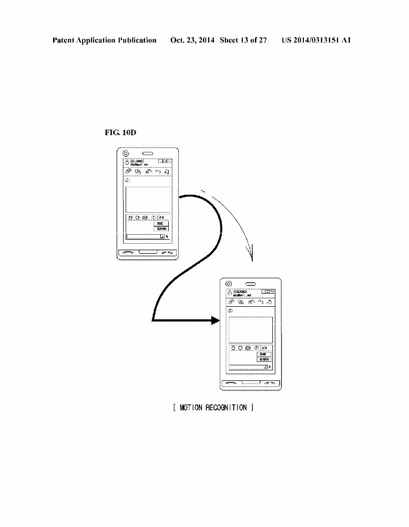
0028 FIG. 13 is a display screen flowchart according to one embodiment of the invention and applied with an idea of the present disclosure to a content view screen relative to image files. 0029 FIG. 14 is a display screen flowchart illustrating according to one embodiment of the invention and including a content view screen relative to image files. 0030 FIG. 15 is a display screen flowchart according to one embodiment of the invention and relating to a message check mode. 0031 FIGS. 16a and 16b are display screen flowcharts according to one embodiment of the invention and relating to a function transmitting messages using a hot-key in a recep tion waiting mode. 0032 FIG. 17 is a display screen flowchart according to one embodiment of the invention and relating to a function connecting a communication via a hot-key in a reception waiting mode. 0033 FIG. 18 is a display screen flowchart according to one embodiment of the invention and relating to a function of communication connection/message transmission via a hot key in a reception waiting mode. 0034 FIG. 19 is a display screen flowchart according to one embodiment of the invention and relating to an image communication mode. 0035 FIG. 20 is a display screen flowchart according to one embodiment of the invention and relating to a DMB (Digital Multimedia Broadcasting) reception mode. 0036 FIG. 21 is a display screen flowchart according to one embodiment of the invention and relating to an image view screen. 0037 FIG. 22 is a display screen flowchart according to one embodiment of the invention and relating to a thumbnail view screen relative to image files. 0038 FIG. 23 is a display screen flowchart according to one embodiment of the invention and relating to an image view screen. 0039 FIG. 24 is a display screen flowchart according to one embodiment of the invention and relating to a text view SCC.
0040 FIG.25a is a display screen flowchart according to one embodiment of the invention and relating to a bell sound set-up screen. 0041 FIG.25b is a display screen flowchart according to one embodiment of the invention and relating to a button/ touch set-up screen. 0042 FIGS. 26a and 26b are display screen flowcharts according to one embodiment of the invention and relating to a video reproduction mode.
DETAILED DESCRIPTION OF THE INVENTION
0043. Before describing the invention, certain terms employed in the specification, examples and appended claims are, for convenience, collected here. 0044) The term mode of a portable terminal relates to an operational mode of a portable terminal. Specifically, the term of mode may relate to a state that the portable terminal enters and executes, or a state where the portable terminal is waiting for a user instruction or an event. 0045. In most of cases, mutually different programs (e.g., applications) are loaded in mutually different modes. How ever, a user may classify a call mode and a reception waiting mode just as a mode and recognize them as such. The user
Oct. 23, 2014
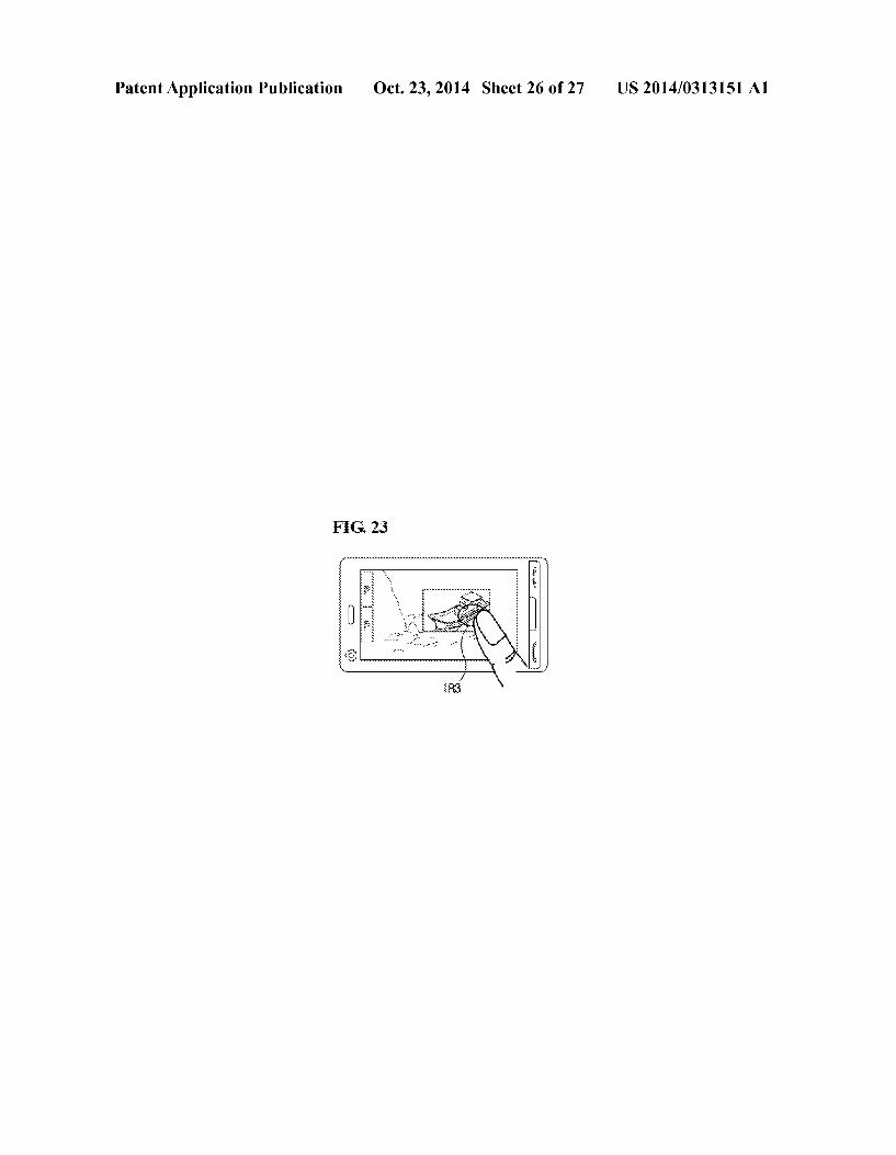
may also consider a game and an instant messenger as an application and recognizes these as such. 0046. The term pattern relates to shapes/designs that are repeated regularly. Here, the shapes/designs do not neces sarily define visible shapes and designs but may represent shapes/designs relative to signal changes of particular param eters within a predetermined time interval. 0047. The term motion pattern in the present description not only defines a displacement pattern explaining a pattern obtained by accumulating position changes of a reference point of a portable terminal (e.g., a center weight point oran attachment position of a sensor) for a predetermined period of time, but also covers a concept having abroader meaning that includes all the information on motions, such as, but not limited thereto, rotational movements, rotational directions and degrees of inclinations relative to gravity directions or cardinal points. 0048. In various embodiments of the invention, the por table terminal may be wirelessly connected to a computer device of a wireless communication network of a provider that provides communication services, and may be connected to an internet service providing server that provides various internet services via the wireless internet communication net work. 0049. The portable terminal described in the present dis closure may refer to a mobile phone, a Smartphone, a note book computer, a digital broadcasting terminal, a PDA (Per sonal Digital Assistance), a PMP (Portable Multimedia Player) and a GPS navigation device and the like. 0050 FIG. 1 is a block diagram of a portable terminal according to an exemplary implementation of the invention. 0051 Referring to FIG. 1, the portable terminal 100 may include a wireless communication unit 110, an A/V (audio/ Video) input unit 120, a manipulation unit 130, a sensing unit 140, an output unit 150, storage 160, an interface unit 170, a controller 180, a power supply unit 190, as well as other elements. It should be noted that two more constituent ele ments may be combined in a single element, or a single element may be divided into two or more elements when in actual implementation. 0.052 Now, these constituent elements will be sequentially described in detail.
0053. The radio communication unit 110 may include a broadcasting reception module 111, a mobile communication module 112, a wireless internet module 113, a short-range communication module 114 and a GPS module 115. 0054 The broadcasting reception module 111 receives broadcasting signal and/or broadcasting related information from an external broadcasting management server (not shown) via abroadcasting channel. The broadcasting channel may include a satellite channel or a terrestrial channel or some other type of communication channel. The broadcasting man agement server may refer to a server that generates and trans mits broadcasting signals and/or broadcasting associated information or a server that receives previously generated broadcasting signals and/or broadcasting associated informa tion and transmits such to a terminal. The broadcasting asso ciated information may refer to information related to a broadcasting channel, a broadcasting program or abroadcast ing service provider. The broadcasting signal may include, not only a TV broadcasting signal, a radio broadcasting sig nal, a data broadcasting signal, but also a broadcasting signal obtained by combining a data broadcasting signal with a TV broadcasting signal or a radio broadcasting signal.

US 2014/03.13151 A1
0055 Meanwhile, the broadcasting associated signal may be provided via a mobile communication network, and in Such a case. Such information may be received by the mobile communication module 112. 0056. The broadcasting associated information may be implemented in various formats. For example, the broadcast ing associated information may include an EPG (Electronic Program Guide) of a DMB (Digital Multimedia Broadcast ing) format, or an ESG (Electronic Service Guide) of a DVB-H (Digital Video Broadcasting-Handheld) format. 0057 The broadcasting reception module 111 receives broadcasting signals by using various digital broadcasting techniques, and particularly, the digital broadcasting signals can be received by using digital broadcasting techniques, such as DMB-T (Digital Multimedia Broadcasting-Terres trial), DMB-T (Digital Multimedia Broadcasting-Satellite), MediaFLO (Media Forward Link Only), DVB-H (Digital Video Broadcasting-Handheld) and ISDB-T (Integrated Ser vices Digital Broadcasting-Terrestrial). It should be also noted that the broadcasting reception module 111 may be configured to be suitable for any other broadcasting technique that provides broadcasting signals and information. 0058. The broadcasting signals and/or broadcasting asso ciated information received via the broadcasting reception module 111 may be stored in the storage 160. 0059. The mobile communication module 112 transmits and receives radio signals to and from at least one device out of a base station, an external terminal and a server of a mobile communication network. Here, the radio signals may include Voice call signals, video (or conference) communication call signals, data in various formats based on the transmission and reception techniques used, text/multimedia messages and other types of information. 0060. The radio internet module 113 refers to a module that Supports a radio access to a network Such as interne, and may be installed in the mobile terminal or may be imple mented as an internal or external element. 0061 The short range communication module 114 refers to a module that Supports short range communications. Suit able technologies for implementing this module may include Bluetooth, RFID (Radio Frequency Identification), IrDA (In frared Data Association), UWB (Ultra Wideband) and Zig Bee. The GPS module 115 receives navigational information from a plurality of satellites. 0062 Meanwhile, the A/V input unit 120 is configured to receive audio signals or video signals and may include a camera module 121 and a microphone module 122. The cam era module 121 function, to process image frames Such as motionless images or videos (moving images) that are obtained by an image sensor in a video call (or video confer ence) mode or in an image capture mode. The processed image frames may then be displayed on a display module 151. 0063. The image frames processed by the camera module 121 may be stored in the storage 160 or transmitted to outside via the wireless communication unit 110. Two or more cam era modules 121 may be provided according to configuration and aspects of the portable terminal. 0064. The microphone module 122 receives an external Sound signals from a microphone in a calling mode, a record ing mode or a voice recognition mode and processes such into an electrical audio (voice) data. The processed audio data may be converted for output into a format that can be transmittable to a mobile communication base station via the mobile com munication module 112 in a calling mode. The microphone
Oct. 23, 2014
module 122 may include various types of noise canceling algorithms (or other processing mechanisms) to cancel noise generated in the course of receiving the external audio sig nals. 0065. The manipulation unit 130 may generate key input data based on user inputs to control the operation of the portable terminal. The manipulation unit 130 may be formed as a key pad, a dome Switch, a touch pad (e.g., employing touch recognition techniques based on pressure, capacitance, resistance and the like), a jog wheel and a jog dial Switch. Particularly, when the touchpad is combined with the display module (151, described later) in a layered structural manner, Such may be called a touch screen. 0066. The sensing unit 140 senses a current state (or con figuration) of the portable terminal (i.e., an opened or closed state), a location (or orientation) of the portable terminal 100, or whether the user has touched certain portion of the portable terminal. Based on Such sensing, a sensing signal for control ling the operation of the portable terminal 100 is generated. 0067 For example, if the portable terminal is a slide-type portable terminal, the sensing unit 140 can sense whether a slide portion of the slide type portable terminal is opened or closed with respect to a main body portion of the portable terminal. In addition, the sensing unit 140 can perform a sensing function to detect whether the power supply unit 190 has supplied power or whether the interface unit 170 is con nected with an external device.
0068. The interface unit 170 functions to interface with various external devices that can be connected with the por table terminal 100. For example, the external devices may include a wired or wireless headset, an external charger, a wired or wireless data port, a card Socket (i.e., for coupling a memory card and a SIM/UIM card), an audio input/output port, a video input/output port, and an earphone. The interface unit 170 may be used to receive data from the external device or be provided with power, such that the received data or power can be delivered to particular elements of the portable terminal 100 or may be used to transmit data and other infor mation from the portable terminal 100 to the external device. 0069. The output unit 150 is configured to provide various types of outputs Such as audio signal, a video signal or an alarm signal and may include a display module 151, an audio output module 152 and an alarm output module 153. 0070 The display module 151 serves to output and display information processed by the portable terminal 100. For example, the display module 151 may display a particular UI (User Interface) or GUI (Graphic User Interface) related to the call operation when the portable terminal 100 is in a calling mode. The display module 151 may display a captured and/or received image, or aparticular UI and/or GUI when the portable terminal 100 is in a video calling mode or an image capturing mode. 0071. As noted above, if the display module 151 and the touch pad are formed together in a layered manner to consti tute a touchscreen, the display module 151 may be used as an input device as well as an output device. The display module 151 may include at least one of a liquid crystal display, a thin film transistor-liquid crystal display, an organic light emitting diode, a flexible display and a three-dimensional (3D) dis play. The display module 151 may include two or more such displays according to particular implementation of the por table terminal 100. For example, the portable terminal 100 may be disposed with external display module (not shown) and internal display modules (not shown) at the same time.
US 2014/03.13151 A1
0072 The audio output module 152 may output audio data that has been received from the radio communication unit 110 in a call signal reception mode, a calling mode, a recording mode, a Voice recognition mode or a broadcasting reception mode, or output audio data which has been stored in the storage 160. In addition, the audio output module 152 may output an audio signal related to a function e.g., a call signal reception Sound and a message reception Sound) performed by the portable terminal 100. The audio output module 152 may include a speaker and a buZZer. 0073. The alarm output module 153 may output a signal that informs about occurrence of an event of the portable terminal 100. The event occurring in the portable terminal 100 may be, for example, a call signal reception requesting a telephone call, a message reception, a key signal input and an alarm that informs a predetermined time. The alarm output module 153 outputs a signal informing about occurrence of an event in a different format other than an audio signal or a Video signal. The alarm unit 153 may output a signal, for example, in the form of vibration. When a call signal or a message is received, the alarm output module 153 may output vibration in order to inform about the received call signal or message. Alternatively, when a key signal is received, the alarm unit 153 may output vibrations as a feedback of the inputted key signal. The user can recognize the occurrence of an event via the vibrations. Additionally or alternatively, the occurrence of an event may be informed to the user via the display module 151 and/or the audio output module 152. 0074 The storage 160 may store software programs (or codes, instructions, etc.) used to Support the processing and controlling performed by the controller 180 and may perform a function for temporarily storing inputted or outputted data (e.g., a phone book, a message, a still image, or Video.). 0075. The storage 160 may include a storage medium of at least one of a flash type memory, a hard disk type memory, a multimedia card, a card type memory (e.g., SD card, XD card, etc.), a RAM and a ROM, just to name a few. In addition, the portable terminal 100 may cooperate with a network storage device capable of performing the storage function of the storage 160 via network access (such as via the Internet). 0076. The controller 180 controls the general operations of the portable terminal. For example, the controller 180 performs the controlling and processing associated with han dling a voice call, data communication, a video call. In addi tion, the controller 180 may include a multimedia reproduc tion module 181 for reproducing multimedia data. The multimedia reproduction module 181 may be formed as a hardware component within the controller 180 or may be formed as a software component separately from the control ler 180. 0077. The controller 180 may identify a proximity touch or a direct touch of the touchscreen by an object (for example, finger of a user) to change the size or area of a screen dis played on the touch screen. To this end, the controller 180 may beformed with a scroll bar or a mini map for controlling the size or area of a screen displayed on the touch screen. The detailed description of the controller 180 will be further given hereinafter. 0078. The power supply 190 receives external power or internal power and Supplies the power required for the opera tion of various elements under the control of the controller 180. 0079. In the above description, the portable terminal according to the present inventive concept has been explained
Oct. 23, 2014
in terms of elements from the perspective of their functions. Hereinafter, the portable terminal according to the present novel concept will be explained in terms of the external ele ments with reference to FIGS. 2 and 3. For simplicity, a touch screen-type portable terminal among various types of por table terminals such as a folder type, a bar type, a Swing type and a slider type will be referred to for explaining the exem plary implementations. However, it can be clearly understood that the features described herein are not limited to the touch screen-type portable terminal, but can be applicable to any type of portable terminal. 0080 FIG. 2 is a front perspective view of the mobile terminal according to one exemplary implementation of the invention. The methods described below may be imple mented in other device configurations as well. I0081. The portable terminal 100 includes a first body 100A and a second body 100B formed to be slidably moving along at least one direction on the first body 100A. In other implementations, the bodies may flip or rotate, or may share a common body. I0082. A state in which the first body 100A is disposed to overlap with the second body 100B may be called a closed configuration, and as shown in FIG.2, a state in which the first body 100A is moved to expose at least a portion of the second body 100B may be called an open configuration. I0083. In the closed configuration, the portable terminal operates mainly in a standby mode, and the standby mode may be released according to a user manipulation. In the open configuration, the portable terminal operates mainly in the calling mode, and the operation state may be changed into the standby mode upon lapse of a certain time or according to user manipulation. 0084. The case (a casing, a housing, a cover and the like) constituting an external appearance of the first body 100A consists of a first front case 100A-1 and a first rear case 100A-2, and various electronic components are installed in a space there between. At least one or more intermediate cases may be additionally disposed between the first front case 100A-1 and the first rear case 100A-2. I0085. The cases may beformed by injection-molding of a synthetic resin or may be made of a metallic material. Such as stainless steel (STS) or titanium (Ti). On the first body 100A {e.g., substantially on the first front case (100A-1)}, the dis play module 151, the first audio output module 152-1, the first camera module 121-1 or a first manipulation unit 130-1 may be disposed. I0086. The display module 151 includes an LCD (Liquid Crystal Display), an OLED (Organic Light Emitting Diode), or the like that visually displays information. I0087. A touchpad may be overlaid (overlapped, superim posed, covered) on the display module 151 in a layered man ner to allow the display module 151 to operate as a touch screen, whereby the user may input information or commands (instructions) by touching the display module 151. I0088. The first audio output module 152-1 may be imple mented as a receiver or a speaker to output various types of Sounds.
I0089. The first camera module 121-1 may be suitably implemented for capturing still images, moving images, vid eos, or other visual information. 0090 The manipulation unit 130-1 receives user com mands (instructions) for controlling network contents repro duction and travel guide operations.

US 2014/03.13151 A1
0091 Like the first body 100A, the case constituting the external appearance of the second body 100B consists of a second front case 100B-1 and a second rear case 100B-2. 0092. A second manipulation unit 130-2 may be disposed on the second body 100B, specifically, on a front face portion of the second front case 100B-1. 0093. A third manipulation unit 130-2, a microphone module 122, and an interface unit 170 may be disposed on at least one of the second front case 100B-1 or the second rear case 100B-2. 0094. The first to third manipulation units 130-1, 130-2, 130-3 may be collectively referred to as the manipulation unit 130, and any means can be employed as the first to third manipulation 130-1, 130-2, 130-3 so long as it can be oper ated in a tactile mariner. 0095 For example, the manipulation unit 130 may be implemented by using one or more dome Switches or touch pads that can receive a user command or information accord ing to press or touch operation by the user, or may be imple mented by using a mechanical manipulation means, such as a rotatable element (e.g., a wheel, dial.jog button, thumb wheel, etc.) or a linear movement element (e.g., a joystick, lever, knob, etc.). 0096. In terms of functions thereof, the first manipulation unit 130-1 may comprise one or more function keys used for inputting a command Such as start, end or scroll, and the second user input unit 130-2 may comprise one or more keypads used for inputting numbers, characters, and symbols. 0097. The third manipulation unit 130-3 may be operated as a so-called hot key for activating a special function of the portable terminal. 0098. The microphone module 122 may be suitably imple mented for receiving a voice of the user or other Sounds. 0099. The interface unit 170 may be used as a passage (path or link) that allows data to be exchanged with an exter nal device through a wired or wireless medium. For example, the interface unit 170 may be at least one of a connection port used for connection of an earjack, earphones, and the like, a communication port that Supports short-range communica tions (e.g., an IrDA port, a BluetoothTM port, a wireless LAN port, etc.), and a power Supply port used for Supplying power to the portable terminal. 0100. The interface unit 170 may include a card socket for receiving or accommodating a card-like medium, Such as a SIM (Subscriber Identification Module) card, a UIM (User Identity Module) card and a memory card for storing infor mation. 0101 The power supply unit 190 may be mounted at the side (or edge) portion of the second rear case 100B-2 for use in supplying power to the portable terminal 100. The power supply unit 190 may be a rechargeable battery, which can be releasably and attachably formed with the portable terminal. 0102 FIG. 3 is a rear perspective view of the portable terminal according to one exemplary implementation. 0103 Referring to FIG.3, a second camera module 121-2 may be additionally mounted on the rear surface of the second rear case 100B-2 of the second body 100B. The second cam era module 121-2 may have an image capture direction which is substantially opposite to that of the first camera module 121-1 (See FIG. 1), and may support a different number of pixels when compared to the first camera module 121-1. 0104 For example, preferably, the first camera module 121-1 is used for low resolution (i.e., supporting a relatively Small number of pixels) to quickly capture an image (or
Oct. 23, 2014
video) of the user's face for immediate transmission to another party during video conferencing or the like, while the second camera module 121-2 is used for high resolution (i.e., Supporting a relatively large number of pixels) in order to capture more detailed (higher quality) images or video which typically do not need to be transmitted immediately. 0105. A flash 121-3 and a mirror 121-4 may be adjacently disposed at the second camera module 121-2. When an image of a subject is captured by the second camera module 121-2, the flash 150 illuminates the subject. The mirror 121-4 allows the user to see himself or herself when he or she wants to capture his or her own image (i.e. perform self-image captur ing) by using the second camera module 121-2. 0106 A second audio output module 152-2 may be addi tionally disposed on the second rear case 100B-2, and may implement a stereophonic function in conjunction with the first audio output module 152-1 (See FIG. 2), and may be also used in a speaker phone mode for call communication. 0107 Abroadcasting signal reception antenna 111-1 may be disposed at one side of the second rear case 100B-2, in addition to an antenna used for call communication. The antenna 111-1 may be installed such that it can be extended from the second body 100B. 0108. One part of a slide module 100C that slidably con nects the first body 100A with the second body 1008 may be disposed on the first rear case 100A-2 of the first body 100A. The other part of the slide module 100C may be disposed on the second front case 100B-1 of the second body 100B, which may not be exposed to the outside as shown in FIG. 3. 0109. In the above description, the second camera module 121-2 and the like are disposed on the second body 100B, but Such exemplary configuration is not meant to be limiting. 0110. For example, one or more of the constituent ele ments 111-1, 121-2, 121-3, 152-2 which are disposed on the second rear case 100B-2 may be mounted on the first body 100A, mainly, on the first rear case 100A-2. In this case, there is an advantage in that those elements disposed on the first rear case 100A-2 can be protectively covered by the second body 100B in the closed configuration. In addition, even if a second camera module 121-2 is not separately mounted, the first camera module 121-1 may be configured to rotate to thereby enable an image capturing up to an image capturing direction of the second camera module 121-2.
0111 FIG. 4 is a schematic view illustrating a structure of a touch screen related to the present disclosure. 0112 Referring to FIG. 4, the display module 151 may be overlaid (overlapped, Superimposed, covered) on the touch pad 400 in a layered manner to allow operating as a touch SCC.
0113. The touchpad 400 illustrated in FIG. 4 is comprised of a squared conduction film 411 made of transparent con ductive material such as ITO (Indium Tin Oxide) and metal electrodes 412-1 to 412-4 each formed at edge of each con ductive film 411. The conductive film 411 may be formed thereon with a protective film 420. 0114. The touch pad 400, a position detection device of capacitive sensing type, is formed with electric field lines between transmission side metal electrodes (T: 412-1, 412-4) and reception side metal electrodes (R: 412-2, 412-3) by an AC (alternating current) Voltage applied to the transmission side metal electrodes (T: 412-1, 412-4). The formed electric field lines are extended to the outside of the touchpad 400 via the protective film 420.

US 2014/03.13151 A1
0115. As a result, when an object (for example, digits of a user) comes near to the touchpad 400 or directly touches the touchpad 400, the electric field lines are partially interrupted to generate a change on the phase and size of the current flowing to the reception side metal electrodes (R: 412-2, 412-3). This is because human body has a static capacity of several pFs relative to the ground to distort the electric field lines formed on the touchpad 400 when a user brings a finger near to or touches the touchpad 400. 0116 Processes (not shown) formed inside the portable terminal 100 may use the current change of the reception side metal electrodes (R: 412-2, 412-3) in response to the touch operation of the object to detect a distance neared by the object and a position where the touch has occurred. 0117. In addition, the object may include not only the finger of the user, but also all the objects capable of identify ing the touch input by the portable terminal 100, by distorting the electric field lines formed on the touchpad 400. 0118 FIG.5 is a schematic view illustrating a principle for detecting a proximity distance of an object using the touch screen of FIG. 4. 0119 Referring to FIG. 5, application of AC voltage 430 to the transmission side metal electrode 412-1 out of metal electrodes 412-1 to 412–4 formed on the transparent conduc tive film 411 makes it possible to form electric field lines (i.e., electric lines of force. 501 to 503 between the transmission side metal electrode 412-1 and the reception side metal elec trode 412-2. The electric field lines 501 to 503 may be exten sively formed to a vertical upward direction (i.e., Z direction) of the touch screen 500. 0120. The amount of electric field lines 501 to 503 inter rupted, by a finger 510 may be changed base on the proximity distance to the touch screen 500 neared by the finger 510 of the user. In other words, as the hand 510 nears the touch screen 500, the finger 510 may increase the influence applied to the electric field lines 501 to 503.
0121. As noted above, the influence applied to the electric field lines 501 to 503 by the finger 510 changes the current applied to current detection units 440-1, 440-2 connected to the metal electrodes 412-1, 412-2, where the current detec tion units 440-1, 440-2 detect the changed current and pro vide the change to an ADC (Analog-to-Digital Converter. 450). The ADC 450 converts the current amount inputted in the form of analog signal to a digital value and provides the digital value to a touch time measurement unit 460. 0122 The touch time measurement unit 460 measures a time stayed by the finger 510 within a touch identification (recognition) effective distance (i.e., d1 of FIG. 5) capable of identifying proximity of the finger 510 by the touchscreen 500 from the information relative to the changed current amount provided by the ADC450. In doing so, the touch time measurement unit 460 may recognize that the proximity touch or direct touch operation is being performed if the finger 510 stays beyond a predetermined time (i.e., 1 second) within the proximity touch identification effective distance (i.e., d1 of FIG. 5). Meanwhile, if the finger 510 stays shorter than a predetermined time (i.e., 1 second) within the proximity touch identification effective distance (i.e., d1 of FIG. 5), the touch time measurement unit 460 may determine that the proximity touch or direct touch operation is not being performed. 0123. If it is determined that there is a touch input in response to the proximity touch or direct touch operation relative to the touchscreen 500, the touch time measurement
Oct. 23, 2014
unit 460 may provide to a distance detection unit 470 infor mation on touch input generation information and current change amount. 0.124. The distance detection unit 460 may calculate a distance between the finger 510 and the touchscreen 500, i.e., a distance separated from the touch screen 500 by the finger 510 toward the vertical upward direction (i.e., Z direction) from the information on the provided current change amount. 0.125 To be more specific, if the finger 510 is positioned at a location nearer than d1 from the vertical direction of the touchpad 400 (i.e., Z direction) but further than d2 (i.e., 20 mm, a location between d1 and d2), the distance detection unit 460 may determine that the finger 510 has entered within the touch identification effective distance from which to detect whether the touchscreen 500 starts to be touched by an external object, and may provide a function corresponding to the proximity touch operation. The proximity touch is defined by a state of an object (i.e., finger of a user) being positioned within the touch identification effective distance of the touch screen 500 for inputting a user command. The proximity touch of the object not directly touching the touchscreen 500 may be distinguished from the direct touch operation that directly touches the touch screen 500 by the object. 0.126 Furthermore, if the finger 510 is positioned on a location nearer than d2 (i.e., 20 mm) from the vertical direc tion of the touchpad 400 (i.e., Z direction) but further than d3 (i.e., 10 mm, a location between d2 and d3), the distance detection unit 460 may determine that the finger 510 has fairly approached the touch screen 500. If the finger 510 is posi tioned on a location shorter than d3 (i.e., 10 mm) (i.e., posi tioned within d3) from the vertical direction of the touchpad 400 (i.e., Z direction) (i.e., positioned within d3) or the finger 510 has directly touched the surface of the touch screen 500, the distance detection unit 460 may determine that the finger 510 has directly touched the touchscreen 500 within the error Scope. I0127. Although the touch operation of the finger 510 has been described in three steps according to the distance between the finger 510 and the touch screen 500, the descrip tion of the touch operation may be classified to four steps for further accuracy. I0128. Successively, a position detection unit 480 may cal culate from information on the changed current amount a position on the touch screen 500 indicated by the finger 510, i.e., a horizontal coordinate of X and y direction on the touch screen 500. They direction is a vertical direction relative to X and Z directions illustrated in FIG. 5. 0129. The measured vertical distance discrete between the finger 510 and the touch screen 500 and the horizontal coor dinate of the finger 510 on the touchpad 400 may be trans mitted to the controller 180. In so doing, the controller 180 may check the user command according to the Vertical dis tance and the horizontal coordinate to perform a control operation in response to the user command and concurrently provide a predetermined graphic user interface (GUI). 0.130 FIG. 6 is a schematic view illustrating a position detection principle of an object using the touchscreen of FIG. 4. I0131 Referring to FIG. 6, when an AC voltage is applied from the AC voltage source to the transmission side metal electrodes 412-1, 412-4 of the touch panel 400, electric field lines (not shown) are formed between transmission side metal electrodes 412-1, 412–4 and the reception side metal elec trode 412-2, 412-3.

US 2014/03.13151 A1
0.132. In addition, if the finger 510 comes near onto the touch panel 400 or directly touches the touch panel 400, current changes are generated to the metal electrodes 412-1 to 412-4. The current detection units 440-1 to 440-4 measure the current changes, and as described above, the position detec tion unit 470 detects the horizontal coordinate (i.e., x-y coor dinate) located on the touch panel 400 by the finger 510 via the current changes and provides the coordinate to the con troller 180. The controller 180 now may recognize the hori Zontal coordinate on the touch screen 500 touched by the finger 510 to perform the user command corresponding to the touch operation and provide the predetermined graphic user interface (GUI) onto the display module 151. 0.133 Although FIGS. 5 and 6 has described the touch time measurement unit 460, the distance detection unit 460 and the position detection unit 480 separately according to their functions, these units 460, 470, 480 may be formed inside the controller 180. 0134. Although the touch screen 500 equipped with the touch panel 400 according to capacitance detection type has been exemplified in FIGS. 4, 5 and 6 to explain the principle of determining the proximity touch and direct touch of object relative to the touch screen 500, there is no limit of arrange ment shapes of the metal electrodes 412-1 to 412-4 of the touchpanel 400 or the kinds of touchpanel 400 as long as the function is provided for detecting the position indicated by the object and the distance between the object and the touch Screen 500.
0135 For example, the touch panel 400 may be embodied to detect a proximity position between the object and the touch panel 400 using a photoelectric sensor that uses laser diodes and light emitting diodes, a high frequency oscillation proximity sensor and electromagnetic proximity sensor. The touch panel may also be embodied by combining the capaci tance detection type and the resistive sensing type by forming metal electrodes on an upper plate or a lower plate for detect ing Voltage changes according to a position pressed by the object. 0136. Now, functions of constituent elements for embody ing the idea of the present disclosure out of constituent ele ments of FIG. 1 and embodiment measures will be emphati cally described. 0.137 The sensing unit 140 of the portable terminal according to the present exemplary implementation may be equipped with a motion detector, Such as a gyro sensor or the like for detecting motion of the portable terminal. 0.138. The manipulation unit 130 may be equipped with a key pad disposed with a plurality of key buttons, and may be formed with a touchscreen for detecting a coordinate value of a point designated by a user. In some exemplary implemen tations, other pointing-receiving devices replacing the touch screen may be used, but the touch screen may be the most appropriate pointing-receiving device in the present exem plary implementation in view of the fact that a user applies a shaking operation to the portable terminal while the touch screen is being touched. 0.139. The controller 180 may interpret a value received from the manipulation unit 130 and a motion pattern detected by the motion detector as a user instruction. Preferably, the controller 180 determines a motion pattern from detection values of the motion detector during a period (e.g., during a period of a particular key button being depressed, or a period of a touch screen being depressed) in which a value received from the manipulation unit 130 keeps a predetermined value.
Oct. 23, 2014
0140. The motion detector may be embodied by a three axis acceleration sensor, which may be selected from various products on the market in consideration of an appropriate size suitable for installation in a portable terminal and perfor aCCS.
0.141. The known method for calculating a displacement in pattern (hereinafter referred to as displacement pattern) using the three-axis acceleration sensoris disclosed in various ways, such that detailed explanation thereto will be omitted herein. But a principle of calculating the displacement pattern using the three-axis acceleration sensor will be explained in the following simple manner. That is, in consideration of the tact that an integral value of an acceleration becomes a speed, and an integral value of the speed becomes a distance that is moved, a displacement pattern of an object installed with the three-axis acceleration sensor can be obtained from accumu lation of the acceleration values relative to orthogonal three axes, if a stopped point is known. 0142. In some exemplary implementations, the motion detector is a two-axis acceleration sensor which is less expen sive than the three-axis acceleration sensor, or a gyro sensor of other methods. The motion detector may further include a one-axis, two-axis or three-axis rotation detection sensor for sensing the rotating motion. The motion detector may calcu late three-axis acceleration values for knowing a gravity direction, or may further include a gravity detection sensor. 0143. In some exemplary implementations, the motion detector may output detection values in various types. For example, the motion detector may output a displacement pattern of a portable terminal, or may simply output three axis acceleration values. The type of output may be deter mined by complexity of displacement pattern to be applied for inputting an instruction. Embodiment of using the dis placement pattern is preferred, when various kinds of instruc tions are involved and displacement patterns are complex, and embodiment of three-axis acceleration output values is preferred, when the number of instructions is limited and displacement patterns are simple. 0144. In some exemplary implementations, the controller 180 may refer to directivity of the motion pattern recognized by the motion detector in order to determine directivity of vibration pattern. This is to allow a user to determine direc tivity of vibration pattern in response to a holding state of a portable terminal, whereby the user can have the same feeling relative to the vibration pattern regardless of the directivity of the potable terminal held by the user. To this end, the vibration generator is preferred to be disposed with two or more vibra tion elements each having a different vibration direction (preferably orthogonal direction). 0145 When the vibration generator is disposed with two or ore vibration elements each having a different vibration direction, the vibration direction of motion pattern applied by a user and vibration direction applied by the vibration gen erator may be correlated. 0146 For example, when a user holds a portable terminal in a lengthwise direction, and an instruction to a particular application is selectively given in a lengthwise vibration direction or a cross-wise vibration direction of the portable terminal, it is assumed that a user has selected the lengthwise vibration direction. At this time, an affirmative response to the user instruction may be embodied by generation of a length wise vibration direction applied by the user, and a negative response to the user instruction may be embodied by genera tion of a cross-wise vibration direction which is the opposite

US 2014/03.13151 A1
direction. To this end, it is preferable that the storage 160 of the portable terminal be disposed with an area for recording a vibration direction of motion pattern applied by the user. 0147 Preferably, the controller 180 may apply an approxi mate value in determining motion patterns because each of the motion patterns (albeit identically recognized by the user) may differ a bit according to user's psychological state. For example, a pattern within a predetermined approximate value from a recorded pattern may be considered as the recorded pattern. 0148. The controller 180 may use one or more parameters selected from a group consisting of displacement, speed, acceleration speed, direction, rotation direction and the parameters are obtained from detection values of the motion detector. One or more of these parameters are used for inter preting motion patterns. The motion patterns recognized by the controller 180 may be divided into reciprocation motion, circular motion, hit or push as instantaneous acceleration, rotation and complex pattern motion (e.g., 8-shaped motion and ZigZag motion). 0149. A predetermined area allocated to the storage 160 of the portable terminal of FIG.1 may be stored with data (e.g., DB) for supporting the driving method of the portable termi nal. 0150. For example, the storage 160 may be equipped with a motion pattern-instruction DB in which one field is allo cated for an identifier of a particular key of depressed state or touch screen (partial or entire area), another field is allocated for motion pattern and still another field is allocated for inter preted instruction. The DB serves to assist the controller 180 in interpreting the user instruction from motion pattern during an input value designated by the manipulation unit 130. 0151 FIG. 7 is a flowchart illustrating a driving method of a portable terminal according to an exemplary implementa tion of the present disclosure. 0152 The driving method using a portable terminal illus trated in FIG. 7 comprises: recognizing a motion of the por table terminal to check an input of a touch screen or a desig nated key button (S120); interpreting a user instruction from a motion pattern comprised of motion detection values of the motion sensing unit while there is an input of the touchscreen or the designated key button (S140); and executing the user instruction (S.160). 0153. The step of S120 may comprise: recognizing motion detection values from the motion detector of the portable terminal (S122); and monitoring, by the controller of the portable terminal, whether the touch screen or a particularly designated key has been depressed (S124). The steps of S122 and S124 may be performed simultaneously, or one of the two steps (S122 and S124) may be performed before the other step, or the other step may be performed after the first step. 0154 The constituent element of manipulation unit 130 for monitoring whether the touch screen or the particularly designated key has been depressed in step S124 may be a key (hereinafter referred to as side key) button (B1) positioned at a side of the portable terminal as illustrated in FIG. 9a, a particular key (hereinafter referred to as gyro key) button (B2) allocated for function setup of the gyro sensor as illustrated in FIG. 9b, a specific partial area (IR1) on the touch screen as illustrated in FIG. 9c, a call/termination key button (K1) as illustrated in FIG. 9d, or may be a software key button (IK1) formed at the touch screen as illustrated in FIG.9e.
0155 As a result of step S120, motion detection values may be obtained that have been accumulated in the period
Oct. 23, 2014
when the touchscreen of the portable terminal or the particu larly designated key button being depressed. The step of S140 may comprise: checking the motion pattern (S142); and inter preting an instruction from the motion pattern (S144). 0156 The controller of the portable terminal in step S142 may detect motion patterns from the accumulated motion detection values. For example, three-axis acceleration values obtained at a predetermined interval may be integrated to obtain three-axis speed values, which is further integrated to obtain three-axis displacement values. Changes of the three axis displacement values would allow directly determining the shapes of the motion patterns. 0157. In some exemplary implementations, the displace ment pattern of a portable terminal may be applied as the motion pattern, or the three-axis acceleration values may be simply applied as the motion pattern. A complex exemplary implementation may include a motion pattern added by direc tions and whether rotation has been effected. 0158 When kinds of instructions to be applied are in large numbers, an embodiment of complex displacement pattern is preferred, and when the kinds of instructions are in small numbers, an embodiment of using a simple value Such as two/three-axis acceleration output values is preferred. A simple push motion may be represented by a two-axis accel eration sensing value, and a motion tilting to a predetermined direction may be given by three-axis acceleration value. 0159 FIGS. 10a to 10d are conceptual drawings illustrat ing concrete motion shapes of a portable terminal applicable as motion patterns according to the idea of the present disclo sure. As illustrated in FIGS. 10a to 10d, kinds of motion patterns may include a tilting (FIG.10a), a 90-degree rotation (FIG. 10b), a shaking (FIG. 10c), a complex motion followed by a push (FIG. 10d). 0160 Meanwhile, parameters discerning each motion pat tern may include strength of shaking as illustrated in FIG. 11a, degree and/or direction of tilting as illustrated in FIG. 11b (i.e., each motion of P1-P8 shown in FIG. 11c may be discernable each other), size of motion as shown in FIG.11c (i.e., each width of motion in P11-P13 of FIG. 11c may be discernable each other), and concrete shapes of motions. 0.161. In step S144 of FIG. 7, in order to determine a user instruction represented by motion pattern detected from step S144, a motion pattern-instruction DB may be used. The DB is comprised of one field for an identifier of a particular key or touch screen (partial or entire area) is depressed, another field for a motion pattern, and still another field for an instruction. 0162. In step S160, the controller 180 may perform in a form of executing an application or a task. Performance of a particular task within an operational system or an application program of a central processing unit in computer equipment is well known, such that the detailed explanation thereto will be omitted. The driving method of a portable terminal in FIG. 7 may be performed during various menu executions, and applied to various operation modes or applications. 0163 A user in the present exemplary implementation may control an operation of the portable terminal by applying two kinds of inputs. The two kinds of inputs include a first input via a manual manipulation unit operated by a motion of a user using a finger, and a second input via a motion detector (gyro sensor) detecting a motion pattern applied to the por table terminal. 0164 Methods for applying the two kinds of inputs may include a method simultaneously applying the first input and the second input, a method sequentially applying the first

US 2014/03.13151 A1
input and the second input within a relatively short waiting time, and a method partially overlapping a time of the first input being applied with a time of the second input being applied. 0.165 Among the three methods, the method of simulta neously applying the first input and the second input is pref erable in terms of user convenience (e.g., when a user applies a shaking operation with a particular key button being depressed) and in order to prevent an erroneous or unintended operation caused by detecting a motion pattern by the por table terminal. However, it should be noted that the three methods are all useable for embodying the idea of the present disclosure, and are within the scope of the present disclosure. 0166 FIG. 8 is a flowchart of a process of a portable terminal detecting a notion pattern that is applied during depression of a designated key button by a user. The portable terminal checks the motion pattern based on motion values detected for a period from a time of the designated key button being depressed to a time of the designated key button being released. The motion values may be periodically obtained using the gyro sensor. 0167 If the above-mentioned process is applied to the flowchart of FIG. 7, the step of S120 of FIG.7 may include checking the depression of the designated key button (S112), starting to detect the motion using the gyro sensor when the depression of the designated key button is generated (S113), and checking the release of the designated key button in the course of motion detection (S114) and terminating the motion detection if the designated key button is released (S116). Meanwhile, a process (S115) of repeating the motion detec tion during depression of the designated key button may be repeated in a form of limitless loop. The method ends when the motion pattern is actually detected (S117). 0168 When the motion detection is finished, the motion pattern is discriminated using the motion values obtained during depression of the designated key button (S142). The step of S142 in FIG. 8 corresponds to the step of S142 of FIG. 7. The discrimination of motion patterns from the periodic acceleration sensing values is known to the skilled in the art such that detailed explanation thereto will be omitted. 0169. In some implementations, the depression of the des ignated key button may be replaced by touch of touch screen or touch of a particular area (e.g., Soft key) on the touch SCC.
(0170 Now, various cases of driving method in FIG. 7 will be described with reference to drawings illustrating a display screen of the portable terminal. 0171 FIG. 12 illustrates a case of enlarging a touched file when a shaking motion is applied during touch by a user of a desired image of the portable terminal equipped with a touch screen. The desired image is on a file list viewed in form of thumbnail list.
0172 An enlargement ratio of a touched file image may be determined by shaking times (frequency) during depression of a desired image (IR2) as shown in the drawing. Further more, it may be also possible to enter into a touched file view mode if applied with the shaking motion during touch of the desired image. (0173 Alternatively, as illustrated in FIG. 13, it may be possible to continuously enlarge an interested image when ever the shaking motion is applied after a particular image (IR2) is selected as the interested image by the depressing motion on the touch screen, and it may be also possible to
Oct. 23, 2014
finally change an entire area of the interested image into a display mode as the shaking motion continues. 0.174. The thumbnailed image file list is easy to touch and
is adequate to realize the above-mentioned ways. However, an image file list arranged in lengthwise format or a message list may also be applied to the present implementation. 0.175 FIG. 14 illustrates an instance where a single image
is selected and displayed when a portable terminal is shaken in a mode of a particular key button being depressed by a user and image files being displayed in a thumbnail or a similar format. 0176 The illustrated thumbnail screen is applied with a design allocated to a different size of area relative to each image in order to increase aesthetic feeling of a user. 0177 Referring to FIG. 14, a normal thumbnail list is displayed on the screen. And a first combination of a particu lar key button and a particular motion pattern gyro key (B2)+shaking on the drawing is applied, an interested image (I, an image to be displayed on an entire screen by a selective operation to be followed) is enlarged larger than other images of thumbnail format, and a second combination of another particular key button and a particular motion pattern gyro key (B2)+tilting on the drawing is applied under this circum stance, the enlarged interested image (IM) is displayed on the entire screen.
0.178 Meanwhile, when the normal thumbnail list is dis played on the screen, and a third combination of a particular key button and a particular motion pattern side key (B1)+ shaking on the drawing is applied, the interested image (I) is displayed on the entire screen. 0179 The first, second and third combination may be dis criminated by allocation of a different key button that is depressed, and/or by application of a different motion pattern. 0180. In some exemplary implementations, when the first combination of aparticularkey button and aparticular motion pattern gyro key (B2)+shaking on the drawing} is applied, any one image on the thumbnail may be randomly set up as a desired image. 0181. In some exemplary implementations, an operation of touching one image among a plurality of thumbnailed images displayed on the touch screen may replace the opera tion of depressing the particular key button. In this case, the touched image is preferably set up as the desired image. 0182 FIG. 15 illustrates an instance where a message of pre-designated content is transmitted to a sender of the mes sage when a user depresses a particular key button to shake a portable terminal and to check the received message. 0183 Referring to FIG. 15, when there is no time by the user who has checked the message to prepare a reply message to a relevant message, and when the user shakes the portable terminal during depression of the gyro key button (B2), the user can send a reply message of a pre-designated commonly used words or phases. 0.184 The illustrated exemplary implementation has a practical advantage because an excuse can be easily obtained from a message sender without generating a noise when a user requests a silence. 0185. Alternatively, when a user shakes the portable ter minal during depression of the particular key button and a call comes in under an awkward environment, the on-going call may be terminated and a pre-determined message may be displayed to the user and/or may be transmitted to the caller who has just dialed up.

US 2014/03.13151 A1
0186 FIG. 16a illustrates an scenario where a message including commonly used words is transmitted to a telephone number registered in hot number when a user shakes a por table terminal in a mode of a message key button (MK) being depressed in the conventional reception waiting mode. 0187. Referring to FIG. 16a, when a user depresses the message key button (MK) to shake the portable terminal, the portable terminal may select a desired phone number among a plurality of Stored phone numbers and send a message in response to a motion pattern. As illustrated, strength of the shaking or the shaking times (frequency) may be applied as parameters of motion patterns that determine the hot number. As shown in FIG. 16b, the message may be one of a com monly-used word list, or a message specially registered for this method. In another embodiment, a first shake or series of shakes may result in a first predetermined word/phrase pre sented to the user to confirm before sending. If the first pre determined word/phrase is not desired, the user can reveal another predetermined word/phrase by again shaking/con trolling the device. 0188 Alternatively, when the portable terminal is in the conventional reception waiting mode, and a user shakes the portable terminal during depression of a message key button, it may be possible to enter into a mode for preparing a mes sage to be sent to the telephone number registered in hot number.
0189 FIG. 17 illustrates an instance where a call connec tion is tried to a telephone number registered in hot number when a user shakes a portable terminal during depression of a call key button in the conventional reception waiting mode of the portable terminal. 0190. Referring to FIG. 17, when a user shakes the por table terminal during depression of the call key button, the portable terminal may select a desired number among a plu rality of hot numbers and try the call connection in response to a motion pattern. The strength of the shaking or the shaking times (frequency) may be used as parameters of motion pat terns that determine the hot number. In another embodiment, a first shake or series of shakes may resultina first hot number presented to the user to confirm before sending. If the first hot number is not desired, the user can reveal another hot number by again shaking/controlling the device. 0191 FIG. 18 illustrates an instance where a call connec tion is tried to a telephone number registered in a numeral hot number, when a portable terminal is shaken in the numerical shape during depression by a user of a particular key (gyro key on the drawing) in the conventional reception waiting mode.
(0192 Referring to FIG. 18, when the user constructs a 2 shape by shaking the portable terminal in a depressed State of the gyro key button (B2), the portable terminal recognizes the motion pattern as 2 and tries to make a call connection to a hot number registered as 2, and when the user constructs a 2 shape by shaking the portable terminal in a depressed state of the message key button (MK), the portable terminal rec ognizes the motion pattern as 2 and transmits a message including commonly-used words to the hot number registered as 2.
0193 In some exemplary implementation, when the por table terminal is shaken during depression of the number key button, a call connection (or a message transmission) may be attempted to a telephone number registered as a number hot number of the key button.
Oct. 23, 2014
0194 FIG. 19 illustrates an instance where an video call view mode is changed, when a user depresses a particularkey button oratouchscreen to apply a shaking motion in the video call mode of a portable terminal. (0195 Referring to FIG. 19, when the user shakes the por table terminal during depression of any one key button, an opponent image enlarged view mode may be changed to my image enlarged view mode. 0196. In some exemplary implementation, a video call mode of a portable terminal equipped with a touchscreen may be changed to a touched image enlarged view mode if the portable terminal is shaken during a touch of a particular image, or the touched image may be transmitted instead. 0.197 FIG. 20 illustrates an instance where a designated operation is performed, when a user depresses a particular key button and shakes a portable terminal in a DMB (Digital Multimedia Broadcasting) reception mode. (0198 Referring to FIG. 20, if a user who has watched the DMB shakes the portable terminal during depression of a call key button (MC), the portable terminal that has outputted the DMB is changed to a preference channel pre-designated by the user. (0199. As illustrated in FIG. 20, if a user who has watched the DMB shakes the portable terminal during depression of a side key button (B1), the portable terminal that has outputted the DMB displays information relative to the currently viewed channel. 0200. As illustrated in FIG. 20, if a user who has watched the DMB shakes the portable terminal during depression of a gyro key button (B2), the portable terminal that has outputted the DMB sets up the currently-viewed channel as a preference channel of the user. 0201 FIG. 21 illustrates an instance where a displayed image is enlarged or reduced, when a user applies a shaking motion during depression of a particular key button in a mode of a particular image file of the portable terminal equipped with a touch screen being displayed. 0202 Referring to FIG. 21, a ratio of a touched file image to be enlarged was determined by the shaking times (fre quency) in a state of an enlargement key button (IK3) formed by an imaginary button at an upper side of the touch screen being depressed, and a ratio of a touched file image to be reduced was determined by the shaking times (frequency) in a state of a reduction key button (IK4) formed by an imagi nary button at a lower side of the touch screen being depressed. Furthermore, the shaking motion may be applied to a portable terminal formed at a side thereofwith an enlarge ment key and a reduction key relative to images. It may be also possible to notify a user the completion of enlargement or reduction of an image via vibration, and to output a vibration while the enlargement or reduction is being progressed. 0203 When an instruction of further reduction is given during display of a single image file on an entire Screen, it may be possible to display a part of a thumbnail list including the image file as shown in the first screen of FIG. 22. 0204 Referring to FIG. 22, when a user applies a tilting motion of the portable terminal upwards (or downwards) of the screen during display of a part of the thumbnail list rela tive to the image file, a thumbnail of further up position (or further down position) may be displayed, and when a hori Zontally-tilted motion (left or right) is performed, a left (or right) thumbnail may be displayed. An entire image of the thumbnail list may have a brighter resolution than that of the display of the portable terminal. Even in this case, the user

US 2014/03.13151 A1
may be notified of the progress of movement of the thumbnail image or completion of the movement of the thumbnail image via vibration or effect Sound. Thus, a user may scroll a plu rality of images with a predetermined motion. Alternatively, a user may scroll a Zoomed single image with a predetermined image. 0205. In addition, when a user applies a tilting motion of the portable terminal upwards (or downwards) of the screen during display of a part of text relative to the image file, text of further up position (or further down position) may be displayed, and when a horizontally-tilted motion (left or right) is performed, left (or right) text may be displayed. An entire image of the text may have a brighter resolution than that of the display of the portable terminal. Even in this case, the user may be notified of the progress of movement of the thumbnail image or completion of the movement of the thumbnail image via vibration or effect Sound. Thus, a user may scroll text with a predetermined motion. 0206 FIG.23 illustrates a circumstance where an image is enlarged and displayed about a touched area in a mode of a particular image file of a portable terminal mounted with a touch screen being displayed, if a user applies a shaking motion during touch of a desired area (IR3) of the displayed image. 0207 Although not shown in the drawing, when another vibration pattern distinguishable from vibration pattern for enlargement is applied during touch by a user of a desired area on the image, it may be possible to display the image in reduced format about the touched area. Furthermore, the completion of enlargement or reduction of the image may be notified to the user via vibration or effect sound.
0208 FIG. 24 illustrates an instance where a font of a displayed text is enlarged or reduced, when a user applies a shaking motion during depression of a particular key button in a mode of a particular text of a portable terminal formed with a touch screen being displayed. 0209 Referring to FIG. 24, a ratio of enlarging a font of the text was determined according to the shaking times (fre quency) during depression of an enlargement key button (IK5) located at a lower area of the touch screen of the portable terminal. Furthermore, it is possible to determine a ratio of reducing the font according to the shaking motion during depression of a reduction key button (IK6) positioned at a lower area of the touch screen of the portable terminal. The determination of ratio of enlargement or reduction of a font may be also applied to a portable terminal having an enlargement key and a reduction key at a side thereof. Fur thermore, the user may be notified of completion of enlarge ment or reduction of the font via vibration. The progress of enlargement or reduction of the font may be also notified to the user via vibration.
0210 FIG. 25a illustrates an instance where volume of bell sound is set up by the shaking times (frequency), when a user applies a shaking motion during touch of a bell Sound volume icon area (IR5) on a touch screen in a mode of a bell Sound setup menu of a portable terminal equipped with the touch screen. 0211 Furthermore, FIG.25b illustrates an instance where volume of sound effect is set up by the shaking times (fre quency) when a button is depressed, when user applies a shaking motion during touch of a button Volume icon area (IR6) on a touch screen in a mode of executing a button volume setup menu of a portable terminal disposed with the touch screen.
Oct. 23, 2014
0212. In both instances of FIGS. 25a and 25b, a user may be notified of completion of volume setup via vibration (or effect sound). Furthermore, when a predetermined delay time lapses and after Volume of sound is designated by the shaking motion, the designated Volume of Sound may be automati cally set up. 0213 FIG. 26a illustrates an instance where a video is enlarged and/or an aspect ratio is changed in response to the shaking times (frequency), when a user applies a shaking motion while touching a video reproduction area of a touch screen in a video reproduction mode of a portable terminal disposed with the touch screen. 0214 FIG. 26b illustrates an instance where volume is adjusted at a ratio in response to the shaking times (fre quency), when a user applies a shaking motion during depres sion of a gyro key button (B2) located at a side of a portable terminal in a video reproduction mode of the portable termi nal disposed with a touch screen. In both instances of FIGS. 26a and 26b, a user may be notified of completion of volume setup via vibration (or effect sound). 0215. Alternatively, a user may fast forward or fast reverse through a video with a predetermined motion of the device. 0216 Furthermore, an electronic dictionary application may be loaded to search for a particular word, when a user applies a shaking motion during touch of the particular word included in a displayed text, in a mode of the text being displayed on a touch screen of a portable terminal. 0217. In the present exemplary implementation, it is pref erable that a smart phone having an excellent multitasking operating system be applied, as it is easier to apply the mul titasking operating system. 0218. It should be understood that the portable terminal operable by an input of a manual manipulation unit and an input of motion pattern should not be construed as limitations on the scope of the present disclosure or of what may be claimed, but rather as descriptions of features specific to particular implementations of the invention. Certain features that are described in this specification in the context of sepa rate implementations can be selectively implemented in part or in combination of all the implementations. 0219. Although specific implementations of the disclo Sure have been disclosed, those having ordinary skill in the art will understand that changes can be made to the specific implementations without departing from the spirit and scope of the disclosure. The scope of the invention is not to be restricted, therefore, to the specific implementations, and it is intended that the appended claims cover any and all Such applications, modifications, and implementations within the Scope of the present disclosure. 0220. It should be also noted that although specific imple mentations of the disclosure have been disclosed mainly on the shaking motion, other implementations are within the Scope of the following claims. For example, other motions Such as tilting, pushing, turning and the like that can replace the shaking motion may be applied, which still achieve desir able results and are within the scope of the present disclosure. What is claimed is: 1. A portable terminal, comprising: a touch screen configured to receive a touch input and
display a plurality of images; a motion sensing unit configured to sense a motion of the
portable terminal; and a controller operatively connected to the motion sensing
unit and the touch screen, and configured to:

US 2014/03.13151 A1
receive, via the touch screen, a touch input to select a particular image among the displayed plurality of images, and
change a size of the selected image, in response to a com bination of the touch input to the particular image and the motion sensed by the motion sensing unit.
2. The portable terminal of claim 1, wherein the controller enlarges the selected image each time a shaking motion of the portable terminal is sensed while the touch input to the par ticular image is maintained.
3. The portable terminal of claim 1, wherein the controller controls the touch screen to display the selected image on an entire display area of the touch screen, when a plurality of motions of the portable terminal are sensed by the motion sensing unit while the touch input to the particular image is maintained.
4. The portable terminal of claim 1, wherein the touch screen displays the plurality of images in a lengthwise format.
5. The portable terminal of claim 1, wherein the plurality of images are displayed in different sizes on the touch screen.
6. The portable terminal of claim 1, wherein when the size of the selected image is enlarged in response to the combina tion of the touch input to the particular image and the motion sensed by the motion sensing unit, the controller controls the touchscreen to display the enlarged image in a size larger than other images among the displayed plurality of images.
7. The portable terminal of claim 1, wherein when another combination of a touch input to the touch screen and a motion of the portable terminal is detected, the controller randomly selects any one of the displayed plurality of images, and changes a size of the randomly selected image.
8. A portable terminal, comprising: a touch screen configured to receive a touch input and
display a plurality of images including a first image: a motion sensing unit configured to sense a motion of the
portable terminal; and
12 Oct. 23, 2014
a controller operatively connected to the motion sensing unit and the touch screen, and configured to:
change an image being displayed on touch screen from the first image to at least one second image, in response to a combination of the touch input to the touch screen and the motion sensed by the motion sensing unit.
9. The portable terminal of claim 8, wherein when the sensed motion includes an upward or downward tilting motion of the portable terminal, the controller controls the touch screen to display upwardly or downwardly scrolled images among the plurality of images.
10. The portable terminal of claim 8, wherein when the sensed motion includes a horizontally tilting motion of the portable terminal, the controller controls the touch screen to display side scrolled images among the plurality of images.
11. The portable terminal of claim 10, wherein the hori Zontally tilting motion includes a right side tilting motion or a left side tilting motion.
12. The portable terminal of claim8, wherein the controller controls the touch screen to scroll through the plurality of images according to a motion of the portable terminal.
13. The portable terminal of claim 8, wherein the at least one second image is displayed on the touch screen to be brighter than the first image.
14. The portable terminal of claim8, wherein the controller controls the portable terminal to notify a user using a vibra tion or sound of the portable terminal, when the changing of the image from the first image to the at least one second image is completed.
15. The portable terminal of claim8, wherein the controller controls the portable terminal to notify a user using a vibra tion or sound of the portable terminal, when the changing of the image from the first image to the at least one second image is in progress.