Embed Size (px)
Citation preview
Golder Associates Inc.
18300 NE Union Hill Road, Suite 200 Redmond, Washington, USA 98052
T: +1 425 883-0777 +1 425 882-5498
Golder and the G logo are trademarks of Golder Associates Corporation golder.com
1.0 INTRODUCTION
This technical memorandum presents the results of Golder Associates Inc.’s (Golder’s) geotechnical investigation
for the City of Redmond Smith Woods Park project. This investigation is based on the scope of work presented in
the proposal dated March 29, 2019, in which Osborn Consulting Inc. (OCI) is the prime consultant to the City of
Redmond and Golder is a sub-consultant to OCI.
1.1 Project Description
Smith Woods Pond is a manmade pond located on the south end of Smith Woods Park and fed by a small stream
that flows generally north to south through Smith Woods Park. Original pond construction included an outflow pipe
that ran beneath the south embankment of the pond. The outflow pipe became damaged causing water levels to
overtop the berm. To reduce the risk of flooding, the City of Redmond lowered the water level in the pond by
cutting a channel through the east side of the berm, allowing for pond discharge to bypass the outlet structure and
drain directly into the stream.
The purpose of this work is to complete a geotechnical investigation to support development of conceptual
designs and cost estimates for preliminary design of the rehabilitation of the pond and/or stream. Geotechnical
recommendations will be developed for the following options:
Alternative 1: Rebuild a pond approximately to its current size (size after the emergency work).
Alternative 2: Remove the berm and restore stream channel through the site.
1.2 Scope of Work
This investigation assesses material types of the berm and native soils for the feasibility and support rehabilitation
design. The proposed scope of work included in this report is as follows:
Conduct a site investigation by conducting four dynamic cone penetration tests (DCPTs) and four hand
augers to assess subsurface soil and water conditions.
Conduct laboratory testing on selected soil samples.
TECHNICAL MEMORANDUMDATE September 26,2 019 Project No. 18111326
TO Rhett Winter, PE Osborn Consulting Inc.
CC
FROM Margaret Pryor, PE and Scott Stoneman, PE EMAIL [email protected]
SMITH WOODS PARK PROJECT GEOTECHNICAL SITE INVESTIGATION

Rhett Winter, PE Project No. 18111326
Osborn Consulting Inc. September 26, 2019
2
Provide preliminary analysis and recommendations for use in developing 30% design plans as they relate to
subsurface soil conditions, pond substrate material, groundwater conditions, existing berm stability and
proposed geotechnical design recommendations for berm repair and earthwork design.
2.0 FIELD INVESTIGATION
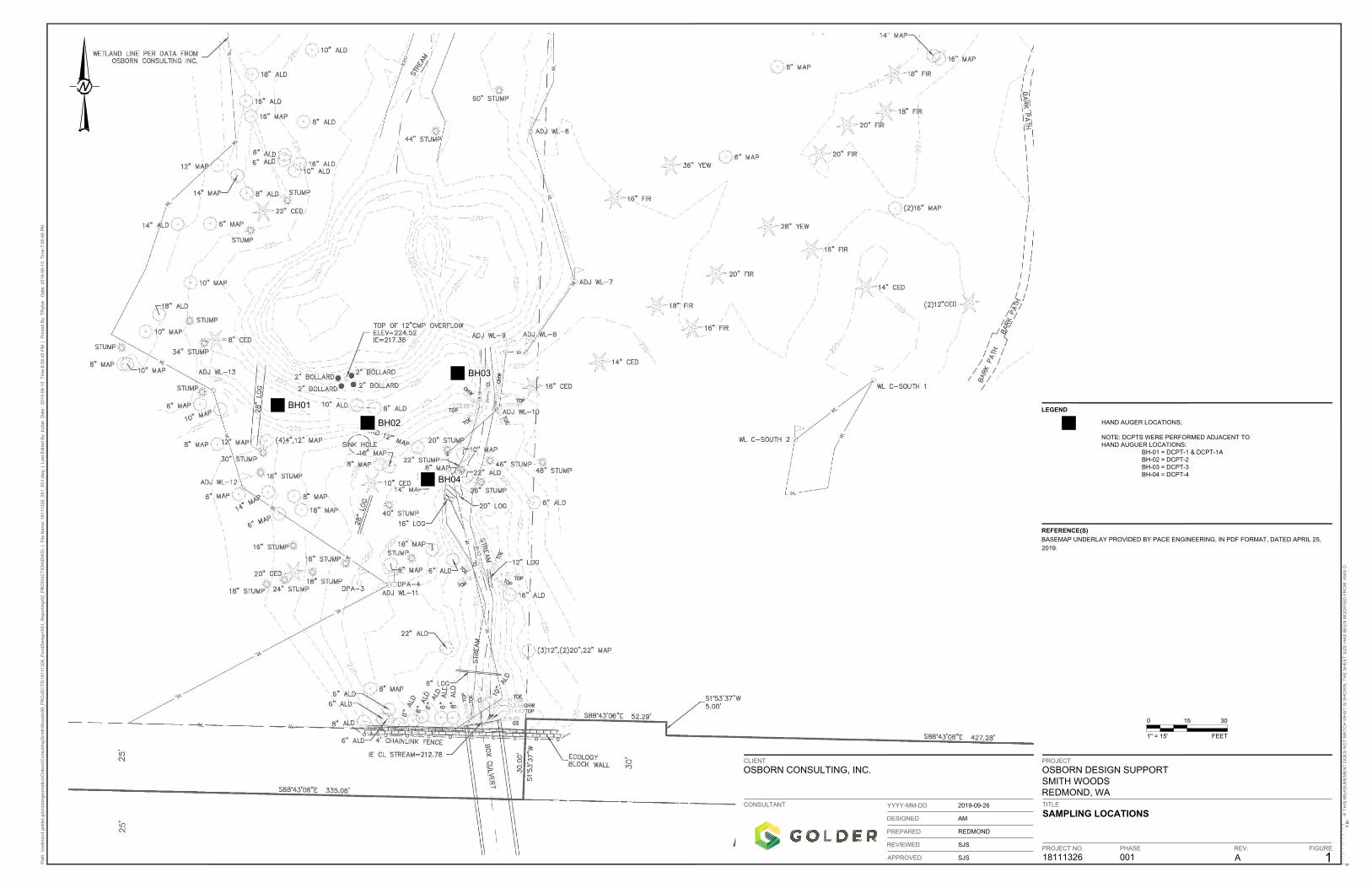
Golder conducted a field investigation on May 9, 2019 that included four hand auger borings and five Dynamic
Cone Penetrometer Tests (DCPTs). Each exploration location included a hand auger boring and DCPT with three
explorations performed on the crest of the berm, BH-01 (DCPT-1 and -1A), BH-02 (DCPT-2), and BH-03 (DCPT-
3), and BH-04 (DCPT-4) conducted near the toe of the berm. The locations were selected based on site
conditions and accessibility and are shown on Figure 1.
2.1 Hand Auger
Hand auger borings were advanced using a 4-inch diameter hand-operated bucket auger. Cuttings obtained by
augering were logged by a Golder geologist on site. The holes were terminated when the auger could no longer
be advanced. Auger cuttings were used to visually assess subsurface soil conditions. Logs of the holes are
presented in Appendix A. The stratigraphic contacts shown on the logs represent the approximate locations
between soil units; actual transitions may be more gradual. The subsurface conditions depicted are only for the
specific dates and locations reported and, therefore, are not necessarily representative of conditions at other
locations and/or times. Subsurface water conditions were recorded during drilling based on our observations and
were not based on stabilized levels prior to backfilling the holes.
2.2 Dynamic Cone Penetrometer Tests
Five Dynamic Cone Penetrometer Tests were conducted adjacent to the hand auger borehole locations and were
performed in accordance with ASTM Standard D6951. A 35-pound hammer mounted on a steel rod with a
disposable 1.41-in-diameter cone-shaped tip was repeatedly dropped from a height of 22.6 inches. The number of
blows required to advance the rod each 10-centimeter (cm) increment was recorded. The rod was advanced until
refusal (greater than 50 blows for one 4-inch increment) was encountered. This data is correlated to Standard
Penetration Test data (ASTM 1586). DCPT data is presented in Appendix B.
2.3 Soil Sampling
Bulk samples were collected from cuttings obtained from the various soil types encountered in the hand auger
holes. The samples were placed in plastic bags and sealed to reduce moisture loss and returned to our laboratory
in Redmond, Washington. In addition, a bulk sample of berm material was collected from the center of berm near
BH-02 using a shovel and the material was placed in a five-gallon bucket.
2.4 Laboratory Testing
Selected samples retrieved from the field investigation were tested to verify field classifications. Two native soil
samples were selected for testing and a sample comprising embankment slough at BH-04 was also tested. In
addition, a bulk composite sample consisting of embankment fill material was selected for testing. A summary of
the laboratory tests conducted for this investigation is presented in Table 2-1.

Rhett Winter, PE Project No. 18111326
Osborn Consulting Inc. September 26, 2019
3
Table 2-1: Summary of Laboratory Tests
Test Number of Tests Test Method
As-Received Moisture Content 4 ASTM D 2216
Atterberg Limits 3 ASMT D 4318
Particle Size Distribution 2 ASTM D 6913
Particle Size – Minus #200 Wash 2 ASTM C 117
Grain size distribution tests (ASTM D6913) and minus #200 wash tests (ASTM C117) were performed using
mechanical sieve analyses and provides the distribution of soil particles between 3- inches and No. 200 U.S.
Sieve. Atterberg limit tests (ASTM D4318) were performed as a standard engineering index test that
determines the range of water contents at which a soil changes consistency. The difference between the
liquid limit moisture content and the plastic limit moisture content is the plasticity index (PI) and provides an
assessment of plasticity for a soil. Laboratory test results are presented in Appendix C.
3.0 SITE CONDITIONS
The pond is situated in the southwest portion of the park in a wetland. The surface of the berm is generally
moderately to densely vegetated with grasses and small shrubs and trees. The surrounding area is undeveloped
and densely vegetated. It should be noted that future geotechnical exploration, if required, may necessitate the
removal of trees and large shrubs to provide access for exploration equipment.
Based on site topography developed by Pace Engineers dated April 25, 20191, the berm embankment along the
south side of the pond appears to range from about 4 to 5 feet in height with side slopes ranging from 2H:1V
(horizontal:vertical) to 3H:1V.
3.1 Soil Conditions
Golder reviewed the geologic map for the site: Geologic Map of the Redmond Quadrangle, King County,
Washington, United States Geological Survey, Miscellaneous Field Studies Map MF-2016 by J.P. Minard and
D.B. Booth, 1988. The map indicates site geology consists of Vashon till. In general, observed subsurface soils
generally consisted of embankment fill overlying recent fluvial deposits ranging in thickness from 1 to 3-feet
underlain by glacial till. The soil layers encountered during the subsurface exploration are described as follows:
Embankment Fill: Very loose to loose, moist, brown, silty fine to coarse sand with little to some low plastic
to elastic fines and few fine to coarse subangular to subrounded gravel, trace cobbles, and trace organics
and rootlets. Some embankment fill material was observed near the toe of the berm within the upper portion
of BH-04. This material could have been placed during previous construction activities or could be slough
from the embankment.
Recent Fluvial Deposits: Moist, nonplastic to low plasticity, very loose to loose, brown and gray ranging in
thickness from about 1 to 3-feet.
1 Boundary and Topographic Survey, prepared by Pace Engineers for Osborn Consulting Inc., dated 4-25-2019
Rhett Winter, PE Project No. 18111326
Osborn Consulting Inc. September 26, 2019
4
Vashon Glacial Till (Qvt): Dense to very dense, moist, gray, silty fine to medium sand with some fine to coarse gravel and trace cobbles.
Pond Substrate: Although the pond substrate material was not visible (below pond water level) during the site reconnaissance, it is assumed the substrate material comprises silty sand with variable thickness underlain by native fluvial deposits and/or till.
3.2 Subsurface Water Conditions
Based on our observations during the field exploration, subsurface water was estimated to be approximately
7 feet below the west end of the embankment crest (observed in BH-1) and about 3 to 4 feet below the base of
the berm (observed in BH-4). Groundwater levels adjacent to the pond and stream should be estimated at the
same level of the pond and stream. Localized groundwater levels may be higher during the winter months.
3.3 Geologic Hazards
The following data was obtained from the Washington State Department of Natural Resources – Geologic
Information Portal online data (https://geologyportal.dnr.wa.gov/#natural_hazards ). A critical areas review
indicates that erosion, landslide, and seismic hazard areas are not mapped for the project site (See RZC
21.064.060).
A brief discussion of geologic hazards is summarized as follows:
Fault Displacement: The nearest documented fault trace to the project site is an unnamed fault that is part
of the Southern Whidbey Island Fault Zone. No mapped faults traverse the project site. Therefore, fault
rupture is not anticipated to be a hazard.
Liquefaction Potential: Loose granular soils located below the water table are generally considered to be
susceptible to liquefaction. Soft, fine grained soils with low plasticity and high water contents may also be
susceptible to liquefaction. The liquefaction potential map indicates liquefaction susceptibility in this area is
very low. In agreement to the mapping, dense soils were observed ranging in depth from 2 to 4 feet below
the base of the berm. Based on the field data and the anticipated geology at the site, liquefaction potential in
the project area is considered very low.
Lateral Spreading/Landslides: Sloughing or sliding of the slopes may occur; however, due to the relatively
low height of the berm and the shallow side slopes, the potential is low. No landslides were mapped in the
surrounding area of the pond. Lateral spreading is typically the result of liquefaction. As previously
described, liquefaction potential is very low and therefore, lateral spreading potential is very low.
4.0 GEOTECHNICAL RECOMMENDATIONS
The following provide a general discussion of the geotechnical considerations and recommendations for design
and construction of the project:
4.1 Rebuild Pond Embankment
Based on our field exploration, compaction of the pond embankment fill does not appear to be adequate as
fill soils were observed to be in a very loose to loose condition. If the pond embankment is to be rebuilt, all
existing embankment materials should be removed.
Rhett Winter, PE Project No. 18111326
Osborn Consulting Inc. September 26, 2019
5
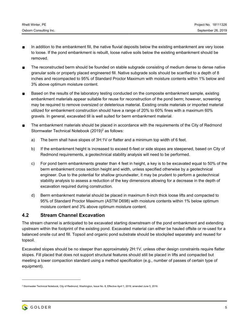
In addition to the embankment fill, the native fluvial deposits below the existing embankment are very loose
to loose. If the pond embankment is rebuilt, loose native soils below the existing embankment should be
removed.
The reconstructed berm should be founded on stable subgrade consisting of medium dense to dense native
granular soils or properly placed engineered fill. Native subgrade soils should be scarified to a depth of 8
inches and recompacted to 95% of Standard Proctor Maximum with moisture contents within 1% below and
3% above optimum moisture content.
Based on the results of the laboratory testing conducted on the composite embankment sample, existing
embankment materials appear suitable for reuse for reconstruction of the pond berm; however, screening
may be required to remove oversized or deleterious material. Existing onsite materials or imported material
utilized for embankment construction should have a range of 20% to 60% fines with a maximum 60%
gravels. In general, excavated till is well suited for berm embankment material.
The embankment materials should be placed in accordance with the requirements of the City of Redmond
Stormwater Technical Notebook (2019)2 as follows:
a) The berm shall have slopes of 3H:1V or flatter and a minimum top width of 6 feet.
b) If the embankment height is increased to exceed 6-feet or side slopes are steepened, based on City of
Redmond requirements, a geotechnical stability analysis will need to be performed.
c) For pond berm embankments greater than 4 feet in height, a key is to be excavated equal to 50% of the
berm embankment cross section height and width, unless specified otherwise by a geotechnical
engineer. Due to the potential for shallow groundwater, it may be prudent to perform a geotechnical
stability analysis to assess a reduction of the key dimensions allowing for a decrease in the depth of
excavation required during construction.
d) Berm embankment material should be placed in maximum 8-inch thick loose lifts and compacted to
95% of Standard Proctor Maximum (ASTM D698) with moisture contents within 1% below optimum
moisture content and 3% above optimum moisture content.
4.2 Stream Channel Excavation
The stream channel is anticipated to be excavated starting downstream of the pond embankment and extending
upstream within the footprint of the existing pond. Excavated material can either be hauled offsite or re-used for a
balanced onsite cut and fill. Topsoil and organic pond substrate should be stockpiled separately and reused for
topsoil.
Excavated slopes should be no steeper than approximately 2H:1V, unless other design constraints require flatter
slopes. Fill placed that does not support structural features should still be placed in lifts and compacted but
meeting a lower compaction standard using a method specification (e.g., number of passes of certain type of
equipment).
2 Stormwater Technical Notebook, City of Redmond, Washington, Issue No. 8, Effective April 1, 2019; amended June 5, 2019.
Rhett Winter, PE Project No. 18111326
Osborn Consulting Inc. September 26, 2019
6
4.3 Groundwater Considerations
Shallow groundwater may be encountered during excavation in areas adjacent to the pond and the stream.
Construction dewatering is expected for both pond berm and stream channel reconstruction.
It is unlikely that the proposed pond configuration will significantly affect the seasonal baseflow. Whether the pond is retained and the water level is increased or decreased, or the pond is removed and a new channel is excavated through the pond berm, the seasonal baseflow is anticipated to not be affected from these activities. The pond is
relatively small with no anticipated live storage component. However, if a live storage component was added (e.g.,
the pond could slowly drain during the summer), then a larger pond could potentially increase summer baseflow.
5.0 CONCLUSIONS
Based on our field exploration and geotechnical assessment, the site is suitable for rebuilding the existing pond
although some relatively minor remedial earthworks may likely be required to meet current construction
standards.
We appreciate the opportunity to be part of the design team. Please contact the undersigned if you have any
comments or questions or require additional information.
GOLDER ASSOCIATES INC.
Scott Stoneman, PE Associate
https://golderassociates.sharepoint.com/sites/34703g/technical work/techmemo/final/18111326-tm-revb-smith woods project geotechnical site investigation memo.docx
09/26/2019Margaret L. Pryor, PESnr. Geotechnical Engineer
MLP/SS/em
ATTACHMENTS:
Figure 1: Site Map
Appendix A: Logs
Appendix B: Dynamic Cone Penetration
Tests Appendix C: Laboratory Reports

APPENDIX A
Figure
BH01
BH02
BH03
BH04
01 in
18111326
PHASE
001
FIGURE
1
A
2019-09-26
REDMOND
AM
SJS
SJS
OSBORN DESIGN SUPPORT
SMITH WOODS
REDMOND, WA
OSBORN CONSULTING, INC.
SAMPLING LOCATIONS
TITLE
PROJECT NO. REV.
PROJECTCLIENT
CONSULTANT
PREPARED
DESIGNED
REVIEWED
APPROVED
YYYY-MM-DD
Path: \\redm
ond.golder.gds\data\geom
atics\O
sbornC
onsulting\S
mithW
oods\99_P
RO
JE
CT
S\18111326_P
ondD
esign\001_R
eporting\02_P
RO
DU
CT
IO
N\D
WG
\ | F
ile N
am
e: 18111326_001_001.dw
g | Last E
dited B
y: trybar D
ate: 2019-06-13
T
im
e:6:58:45 P
M | P
rinted B
y: T
Rybar D
ate: 2019-06-13 T
im
e:7:05:49 P
M
IF
T
HIS
M
EA
SU
RE
ME
NT
D
OE
S N
OT
M
AT
CH
W
HA
T IS
S
HO
WN
, T
HE
S
HE
ET
S
IZ
E H
AS
B
EE
N M
OD
IF
IE
D F
RO
M: A
NS
I D
0
FEET
15 30
1'' = 15'
LEGEND
HAND AUGER LOCATIONS;
NOTE: DCPTS WERE PERFORMED ADJACENT TO HAND AUGUER LOCATIONS:
BH-01 = DCPT-1 & DCPT-1ABH-02 = DCPT-2BH-03 = DCPT-3BH-04 = DCPT-4
REFERENCE(S)
BASEMAP UNDERLAY PROVIDED BY PACE ENGINEERING, IN PDF FORMAT, DATED APRIL 25,
2019.

APPENDIX A
Logs
No seepage observed
DEPTH OFHOLE
(ft)
DEPTH TOW/L(ft)
TIME
NO.
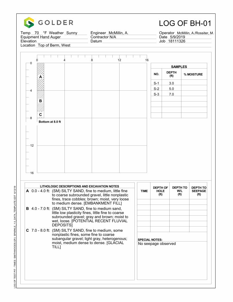
A 0.0 - 4.0 ft: (SM) SILTY SAND, fine to medium, little fineto coarse subrounded gravel, little nonplastic fines, trace cobbles; brown; moist, very loose to medium dense. [EMBANKMENT FILL]
B 4.0 - 7.0 ft: (SM) SILTY SAND, fine to medium sand, little low plasticity fines, little fine to coarse subrounded gravel; gray and brown; moist to wet, loose. [POTENTIAL RECENT FLUVIAL DEPOSITS]
C 7.0 - 8.0 ft: (SM) SILTY SAND, fine to medium, somenonplastic fines, some fine to coarse subangular gravel; light gray, heterogenous; moist, medium dense to dense. [GLACIAL TILL]
DEPTH(ft)
SPECIAL NOTES:
LITHOLOGIC DESCRIPTIONS AND EXCAVATION NOTES
% MOISTURE
3.0
5.0
7.0
0 4 8 12 16
Temp 70 °F Weather Sunny Equipment Hand AugerElevationLocation Top of Berm, West
LOG OF BH-01Engineer McMillin, A. Contractor N/ADatum
Operator McMillin, A./Rossiter, M. Date 5/9/2019Job 18111326
S-1
S-2
S-3
0
4
8
12
16
DEPTH TOSEEPAGE
(ft)
SAMPLES
LOG
OF
TE
ST
PIT
- T
IME
S S
MIT
HW
OO
DS
.GP
J S
PA
RK
LE_1
.0_D
AT
A_T
EM
PLA
TE
.GD
T 6
/13/
19
A
B
C
Bottom at 8.0 ft

No seepage observed
DEPTH OFHOLE
(ft)
DEPTH TOW/L(ft)
TIME
NO.
A 0.0 - 2.0 ft: (SM) SILTY SAND, fine to medium, little fineto coarse subrounded to subangular gravel, little nonplastic fines, trace cobbles; medium brown; moist, very loose to loose.[EMBANKMENT FILL]
DEPTH(ft)
SPECIAL NOTES:
LITHOLOGIC DESCRIPTIONS AND EXCAVATION NOTES
% MOISTURE
0 4 8 12 16
Temp 70 °F Weather Sunny Equipment Hand AugerElevationLocation Top of Berm, Center
Engineer McMillin, A.
LOG OF BH-02
ContractorDatum
Operator McMillin, A./Rossiter, M. Date 5/9/2019Job 18111326
0
4
8
12
16
DEPTH TOSEEPAGE
(ft)
SAMPLES
LOG
OF
TE
ST
PIT
- T
IME
S S
MIT
HW
OO
DS
.GP
J S
PA
RK
LE_1
.0_D
AT
A_T
EM
PLA
TE
.GD
T 6
/13/
19
A
Bottom at 2.0 ftS-1 2.0

No seepage observed
DEPTH OFHOLE
(ft)
DEPTH TOW/L(ft)
TIME
NO.
A 0.0 - 4.0 ft: (SM) SILTY SAND, fine to coarse sand,little to some low plasticity fines, little fine to coarse subrounded gravel, trace subrounded cobbles, trace organics; dark brown; moist, very loose to loose. [EMBANKMENT FILL]
B 4.0 - 6.0 ft: (SM) SILTY SAND, fine to medium, somenonplastic fines, few fine to coarse subangular to subrounded gravel, trace subrounded cobbles; dark brown to gray; moist, very loose to loose. [EMBANKMENT FILL]
DEPTH(ft)
SPECIAL NOTES:
LITHOLOGIC DESCRIPTIONS AND EXCAVATION NOTES
% MOISTURE
3.0
0 4 8 12 16
Temp 70 °F Weather Sunny Equipment Hand AugerElevationLocation Top of Berm, East
Engineer McMillin, A.
LOG OF BH-03
ContractorDatum
Operator McMillin, A./Rossiter, M. Date 5/9/2019Job 18111326
S-1
0
4
8
12
16
DEPTH TOSEEPAGE
(ft)
SAMPLES
LOG
OF
TE
ST
PIT
- T
IME
S S
MIT
HW
OO
DS
.GP
J S
PA
RK
LE_1
.0_D
AT
A_T
EM
PLA
TE
.GD
T 6
/13/
19
A
B
Bottom at 5.0 ft
No seepage observed
DEPTH OFHOLE
(ft)
DEPTH TOW/L(ft)
TIME
NO.
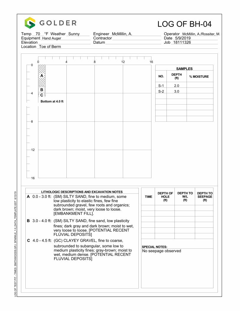
A 0.0 - 3.0 ft: (SM) SILTY SAND, fine to medium, somelow plasticity to elastic fines, few fine subrounded gravel, few roots and organics; dark brown; moist, very loose to loose. [EMBANKMENT FILL].
B 3.0 - 4.0 ft: (SM) SILTY SAND, fine sand, low plasticityfines; dark gray and dark brown; moist to wet, very loose to loose. [POTENTIAL RECENT FLUVIAL DEPOSITS]
C 4.0 - 4.5 ft: (GC) CLAYEY GRAVEL, fine to coarse,subrounded to subangular, some low to medium plasticity fines; gray-brown; moist to wet, medium dense. [POTENTIAL RECENT FLUVIAL DEPOSITS]
DEPTH(ft)
SPECIAL NOTES:
LITHOLOGIC DESCRIPTIONS AND EXCAVATION NOTES
% MOISTURE
2.0
3.0
0 4 8 12 16
Temp 70 °F Weather Sunny Equipment Hand AugerElevationLocation Toe of Berm
Engineer McMillin, A.
LOG OF BH-04
ContractorDatum
Operator McMillin, A./Rossiter, M. Date 5/9/2019Job 18111326
S-1
S-2
0
4
8
12
16
DEPTH TOSEEPAGE
(ft)
SAMPLES
LOG
OF
TE
ST
PIT
- T
IME
S S
MIT
HW
OO
DS
.GP
J S
PA
RK
LE_1
.0_D
AT
A_T
EM
PLA
TE
.GD
T 6
/13/
19
A
B C
Bottom at 4.0 ft

APPENDIX B
Dynamic Cone Penetration Tests

WILDCAT DYNAMIC CONE LOG Page 1 of 1Golder Associates18300 Union Hill Rd. Suite 200 PROJECT NUMBER: 18111326Redmond, WA DATE STARTED: 05-09-2019
DATE COMPLETED: 05-09-2019HOLE #: DCPT-1
CREW: AM and MR SURFACE ELEVATION:PROJECT: Smith Woods Pond WATER ON COMPLETION:
ADDRESS: 176 Ave NE and NE 124 Street HAMMER WEIGHT: 35 lbs.LOCATION: Redmond, WA CONE AREA: 10 sq. cm
BLOWS RESISTANCE GRAPH OF CONE RESISTANCE TESTED CONSISTENCYDEPTH PER 10 cm Kg/cm² 0 50 100 150 N' SAND & SILT CLAY
- 1 4.4 • 1 VERY LOOSE VERY SOFT- 6 26.6 ••••••• 7 LOOSE MEDIUM STIFF- 1 ft 8 35.5 •••••••••• 10 LOOSE STIFF- 7 31.1 ••••••••• 8 LOOSE MEDIUM STIFF- 6 26.6 ••••••• 7 LOOSE MEDIUM STIFF- 2 ft 7 31.1 ••••••••• 8 LOOSE MEDIUM STIFF- 9 40.0 ••••••••••• 11 MEDIUM DENSE STIFF- 9 40.0 ••••••••••• 11 MEDIUM DENSE STIFF- 3 ft 13 57.7 •••••••••••••••• 16 MEDIUM DENSE VERY STIFF- 1 m 14 62.2 •••••••••••••••••• 17 MEDIUM DENSE VERY STIFF- 10 38.6 ••••••••••• 11 MEDIUM DENSE STIFF- 4 ft 7 27.0 ••••••• 7 LOOSE MEDIUM STIFF- 5 19.3 ••••• 5 LOOSE MEDIUM STIFF- 5 19.3 ••••• 5 LOOSE MEDIUM STIFF- 5 ft 4 15.4 •••• 4 VERY LOOSE SOFT--- 6 ft-- 2 m- 7 ft--- 8 ft--- 9 ft--- 3 m 10 ft---- 11 ft--- 12 ft--- 4 m 13 ft
WILDCAT.XLS
ENCOUNTERED REFUSAL AT 5 FEET; MOVED APPROXIMATELY 1 FOOT WEST AND ATTEMPTED A SECOND DCPT NEAR BH-01 - SEE DCPT -1A
WILDCAT DYNAMIC CONE LOG Page 1 of 1Golder Associates18300 Union Hill Rd. Suite 200 PROJECT NUMBER: 18111326Redmond, WA DATE STARTED: 05-09-2019
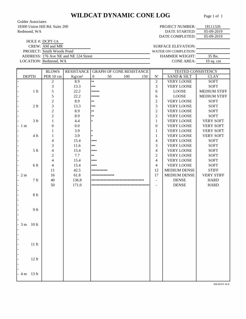
DATE COMPLETED: 05-09-2019HOLE #: DCPT-1A
CREW: AM and MR SURFACE ELEVATION:PROJECT: Smith Woods Pond WATER ON COMPLETION:
ADDRESS: 176 Ave NE and NE 124 Street HAMMER WEIGHT: 35 lbs.LOCATION: Redmond, WA CONE AREA: 10 sq. cm
BLOWS RESISTANCE GRAPH OF CONE RESISTANCE TESTED CONSISTENCYDEPTH PER 10 cm Kg/cm² 0 50 100 150 N' SAND & SILT CLAY
- 2 8.9 •• 2 VERY LOOSE SOFT- 3 13.3 ••• 3 VERY LOOSE SOFT- 1 ft 5 22.2 •••••• 6 LOOSE MEDIUM STIFF- 5 22.2 •••••• 6 LOOSE MEDIUM STIFF- 2 8.9 •• 2 VERY LOOSE SOFT- 2 ft 3 13.3 ••• 3 VERY LOOSE SOFT- 2 8.9 •• 2 VERY LOOSE SOFT- 2 8.9 •• 2 VERY LOOSE SOFT- 3 ft 1 4.4 • 1 VERY LOOSE VERY SOFT- 1 m 0 0.0 0 VERY LOOSE VERY SOFT- 1 3.9 • 1 VERY LOOSE VERY SOFT- 4 ft 1 3.9 • 1 VERY LOOSE VERY SOFT- 4 15.4 •••• 4 VERY LOOSE SOFT- 3 11.6 ••• 3 VERY LOOSE SOFT- 5 ft 4 15.4 •••• 4 VERY LOOSE SOFT- 2 7.7 •• 2 VERY LOOSE SOFT- 4 15.4 •••• 4 VERY LOOSE SOFT- 6 ft 4 15.4 •••• 4 VERY LOOSE SOFT- 11 42.5 •••••••••••• 12 MEDIUM DENSE STIFF- 2 m 16 61.8 ••••••••••••••••• 17 MEDIUM DENSE VERY STIFF- 7 ft 40 136.8 ••••••••••••••••••••••••••••••••••••••• - DENSE HARD- 50 171.0 •••••••••••••••••••••••••••••••••••••••••••• - DENSE HARD-- 8 ft--- 9 ft--- 3 m 10 ft---- 11 ft--- 12 ft--- 4 m 13 ft
WILDCAT.XLS
WILDCAT DYNAMIC CONE LOG Page 1 of 1Golder Associates18300 Union Hill Rd. Suite 200 PROJECT NUMBER: 18111326Redmond, WA DATE STARTED: 05-09-2019
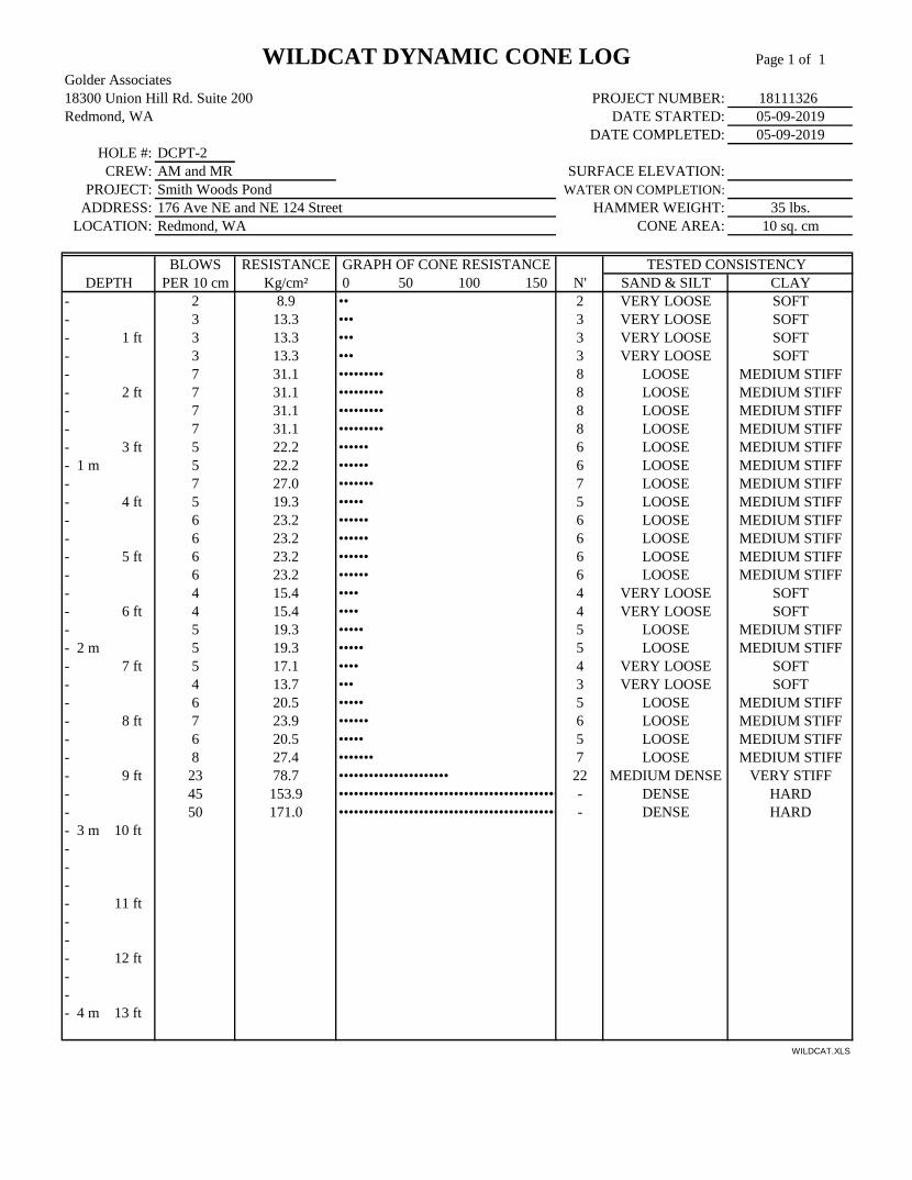
DATE COMPLETED: 05-09-2019HOLE #: DCPT-2
CREW: AM and MR SURFACE ELEVATION:PROJECT: Smith Woods Pond WATER ON COMPLETION:
ADDRESS: 176 Ave NE and NE 124 Street HAMMER WEIGHT: 35 lbs.LOCATION: Redmond, WA CONE AREA: 10 sq. cm
BLOWS RESISTANCE GRAPH OF CONE RESISTANCE TESTED CONSISTENCYDEPTH PER 10 cm Kg/cm² 0 50 100 150 N' SAND & SILT CLAY
- 2 8.9 •• 2 VERY LOOSE SOFT- 3 13.3 ••• 3 VERY LOOSE SOFT- 1 ft 3 13.3 ••• 3 VERY LOOSE SOFT- 3 13.3 ••• 3 VERY LOOSE SOFT- 7 31.1 ••••••••• 8 LOOSE MEDIUM STIFF- 2 ft 7 31.1 ••••••••• 8 LOOSE MEDIUM STIFF- 7 31.1 ••••••••• 8 LOOSE MEDIUM STIFF- 7 31.1 ••••••••• 8 LOOSE MEDIUM STIFF- 3 ft 5 22.2 •••••• 6 LOOSE MEDIUM STIFF- 1 m 5 22.2 •••••• 6 LOOSE MEDIUM STIFF- 7 27.0 ••••••• 7 LOOSE MEDIUM STIFF- 4 ft 5 19.3 ••••• 5 LOOSE MEDIUM STIFF- 6 23.2 •••••• 6 LOOSE MEDIUM STIFF- 6 23.2 •••••• 6 LOOSE MEDIUM STIFF- 5 ft 6 23.2 •••••• 6 LOOSE MEDIUM STIFF- 6 23.2 •••••• 6 LOOSE MEDIUM STIFF- 4 15.4 •••• 4 VERY LOOSE SOFT- 6 ft 4 15.4 •••• 4 VERY LOOSE SOFT- 5 19.3 ••••• 5 LOOSE MEDIUM STIFF- 2 m 5 19.3 ••••• 5 LOOSE MEDIUM STIFF- 7 ft 5 17.1 •••• 4 VERY LOOSE SOFT- 4 13.7 ••• 3 VERY LOOSE SOFT- 6 20.5 ••••• 5 LOOSE MEDIUM STIFF- 8 ft 7 23.9 •••••• 6 LOOSE MEDIUM STIFF- 6 20.5 ••••• 5 LOOSE MEDIUM STIFF- 8 27.4 ••••••• 7 LOOSE MEDIUM STIFF- 9 ft 23 78.7 •••••••••••••••••••••• 22 MEDIUM DENSE VERY STIFF- 45 153.9 •••••••••••••••••••••••••••••••••••••••••••• - DENSE HARD- 50 171.0 •••••••••••••••••••••••••••••••••••••••••••• - DENSE HARD- 3 m 10 ft---- 11 ft--- 12 ft--- 4 m 13 ft
WILDCAT.XLS

WILDCAT DYNAMIC CONE LOG Page 1 of 1Golder Associates18300 Union Hill Rd. Suite 200 PROJECT NUMBER: 18111326Redmond, WA DATE STARTED: 05-09-2019
DATE COMPLETED: 05-09-2019HOLE #: DCPT-3
CREW: AM and MR SURFACE ELEVATION:PROJECT: Smith Woods Pond WATER ON COMPLETION:
ADDRESS: 176 Ave NE and NE 124 Street HAMMER WEIGHT: 35 lbs.LOCATION: Redmond, WA CONE AREA: 10 sq. cm
BLOWS RESISTANCE GRAPH OF CONE RESISTANCE TESTED CONSISTENCYDEPTH PER 10 cm Kg/cm² 0 50 100 150 N' SAND & SILT CLAY
- 2 8.9 •• 2 VERY LOOSE SOFT- 4 17.8 ••••• 5 LOOSE MEDIUM STIFF- 1 ft 5 22.2 •••••• 6 LOOSE MEDIUM STIFF- 7 31.1 ••••••••• 8 LOOSE MEDIUM STIFF- 3 13.3 ••• 3 VERY LOOSE SOFT- 2 ft 4 17.8 ••••• 5 LOOSE MEDIUM STIFF- 4 17.8 ••••• 5 LOOSE MEDIUM STIFF- 5 22.2 •••••• 6 LOOSE MEDIUM STIFF- 3 ft 6 26.6 ••••••• 7 LOOSE MEDIUM STIFF- 1 m 3 13.3 ••• 3 VERY LOOSE SOFT- 5 19.3 ••••• 5 LOOSE MEDIUM STIFF- 4 ft 5 19.3 ••••• 5 LOOSE MEDIUM STIFF- 2 7.7 •• 2 VERY LOOSE SOFT- 1 3.9 • 1 VERY LOOSE VERY SOFT- 5 ft 3 11.6 ••• 3 VERY LOOSE SOFT- 1 3.9 • 1 VERY LOOSE VERY SOFT- 1 3.9 • 1 VERY LOOSE VERY SOFT- 6 ft 1 3.9 • 1 VERY LOOSE VERY SOFT- 2 7.7 •• 2 VERY LOOSE SOFT- 2 m 2 7.7 •• 2 VERY LOOSE SOFT- 7 ft 11 37.6 •••••••••• 10 LOOSE STIFF- 46 157.3 •••••••••••••••••••••••••••••••••••••••••••• - DENSE HARD- 100 342.0 •••••••••••••••••••••••••••••••••••••••••••• - VERY DENSE HARD- 8 ft--- 9 ft--- 3 m 10 ft---- 11 ft--- 12 ft--- 4 m 13 ft
WILDCAT.XLS

WILDCAT DYNAMIC CONE LOG Page 1 of 1Golder Associates18300 Union Hill Rd. Suite 200 PROJECT NUMBER: 18111326Redmond, WA DATE STARTED: 05-09-2019
DATE COMPLETED: 05-09-2019HOLE #: DCPT-4
CREW: AM and MR SURFACE ELEVATION:PROJECT: Smith Woods Pond WATER ON COMPLETION:
ADDRESS: 176 Ave NE and NE 124 Street HAMMER WEIGHT: 35 lbs.LOCATION: Redmond, WA CONE AREA: 10 sq. cm
BLOWS RESISTANCE GRAPH OF CONE RESISTANCE TESTED CONSISTENCYDEPTH PER 10 cm Kg/cm² 0 50 100 150 N' SAND & SILT CLAY
- 0 0.0 0 VERY LOOSE VERY SOFT- 0 0.0 0 VERY LOOSE VERY SOFT- 1 ft 0 0.0 0 VERY LOOSE VERY SOFT- 0 0.0 0 VERY LOOSE VERY SOFT- 2 8.9 •• 2 VERY LOOSE SOFT- 2 ft 3 13.3 ••• 3 VERY LOOSE SOFT- 4 17.8 ••••• 5 LOOSE MEDIUM STIFF- 5 22.2 •••••• 6 LOOSE MEDIUM STIFF- 3 ft 4 17.8 ••••• 5 LOOSE MEDIUM STIFF- 1 m 5 22.2 •••••• 6 LOOSE MEDIUM STIFF- 2 7.7 •• 2 VERY LOOSE SOFT- 4 ft 3 11.6 ••• 3 VERY LOOSE SOFT- 21 81.1 ••••••••••••••••••••••• 23 MEDIUM DENSE VERY STIFF- 15 57.9 •••••••••••••••• 16 MEDIUM DENSE VERY STIFF- 5 ft 20 77.2 •••••••••••••••••••••• 22 MEDIUM DENSE VERY STIFF- 18 69.5 •••••••••••••••••••• 19 MEDIUM DENSE VERY STIFF- 29 111.9 •••••••••••••••••••••••••••••••• - DENSE HARD- 6 ft 28 108.1 ••••••••••••••••••••••••••••••• - MEDIUM DENSE VERY STIFF- 44 169.8 •••••••••••••••••••••••••••••••••••••••••••• - DENSE HARD- 2 m 73 281.8 •••••••••••••••••••••••••••••••••••••••••••• - VERY DENSE HARD- 7 ft--- 8 ft--- 9 ft--- 3 m 10 ft---- 11 ft--- 12 ft--- 4 m 13 ft
WILDCAT.XLS
APPENDIX C
Laboratory Reports

6/17/19
PROJECT NAME:SAMPLE ID: 4-7'TYPE:
Osborn/Smith Woods/WA BH-01 S-2Grab Sample
Coarse Fine Coarse Medium Fine Silt or Clay
COBBLES GRAVEL SAND FINES
Particle Size
(mm) % Passing Classification Percentage Moisture Content
12.0" 304.8 9.766.0" 154.23.0" 75 Cobbles 0.02.5" 63.52.0" 501.5" 37.51.0" 25
0.75" 19 Coarse Gravel 0.00.375" 9.5
#4 4.75 Fine Gravel 0.0#10 2.00 Coarse Sand 0.0#20 0.85#40 0.43 Medium Sand 0.0#60 0.25
#100 0.15#200 0.075 18.7 Fine Sand
Fines 18.7
D60= D30= D10=
DESCRIPTION:
TECH RBKUSCS: SM DATE 6/17/19
CHECK MLPREVIEW JH
18111326.000
Minus #200 WashASTM C117-17
Particle Size
0
10
20
30
40
50
60
70
80
90
100
0.0010.010.11101001000
%
Passing
Particle size in millimeters
12" 3" 2" 1" 3/8" #4 #10 #20 #40 #60 #100 #2003/4"
U.S
. Sta
ndar
d Si
eves
Siz
es a
nd N
umbe
rs
Golder Associates Inc.
6/17/19
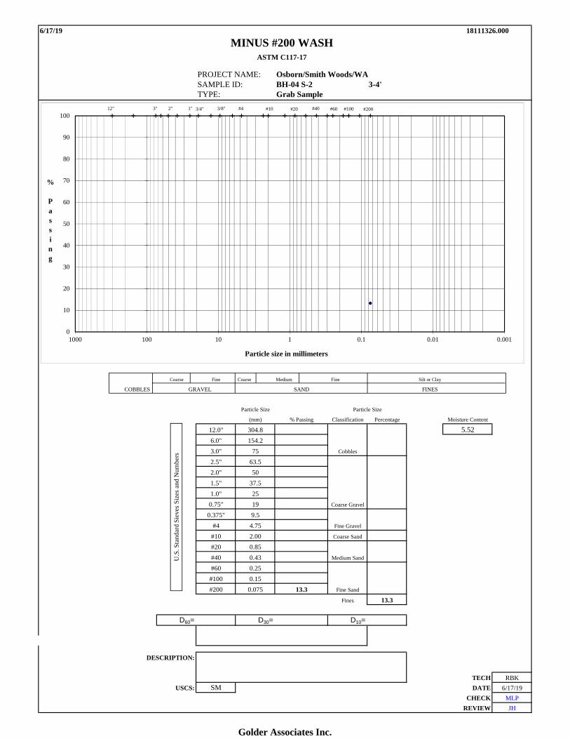
PROJECT NAME: Osborn/Smith Woods/WA SAMPLE ID: BH-04 S-2 3-4'TYPE: Grab Sample
Coarse Fine Coarse Medium Fine Silt or Clay
COBBLES GRAVEL SAND FINES
Particle Size
(mm) % Passing Classification Percentage Moisture Content
12.0" 304.8 5.526.0" 154.23.0" 75 Cobbles
2.5" 63.52.0" 501.5" 37.51.0" 25
0.75" 19 Coarse Gravel
0.375" 9.5#4 4.75 Fine Gravel
#10 2.00 Coarse Sand
#20 0.85#40 0.43 Medium Sand
#60 0.25#100 0.15#200 0.075 13.3 Fine Sand
Fines 13.3
D60= D30= D10=
DESCRIPTION:
TECH RBKUSCS: SM DATE 6/17/19
CHECK MLPREVIEW JH
18111326.000
MINUS #200 WASHASTM C117-17
Particle Size
0
10
20
30
40
50
60
70
80
90
100
0.0010.010.11101001000
%
Passing
Particle size in millimeters
12" 3" 2" 1" 3/8" #4 #10 #20 #40 #60 #100 #2003/4"
U.S
. Sta
ndar
d Si
eves
Siz
es a
nd N
umbe
rs
Golder Associates Inc.

6/17/19
PROJECT NAME: Osborn/Smith Woods/WA SAMPLE ID: BH-04 S-1 0-3'TYPE: Grab Sample
Coarse Fine Coarse Medium Fine Silt or Clay
COBBLES GRAVEL SAND FINES
Particle Size
(mm) % Passing Classification Percentage Moisture Content
12.0" 304.8 100.0 10.606.0" 154.2 100.03.0" 75 100.0 Cobbles 0.02.5" 63.5 100.02.0" 50 100.01.5" 37.5 100.01.0" 25 100.0
0.75" 19 100.0 Coarse Gravel 0.00.375" 9.5 94.1
#4 4.75 88.9 Fine Gravel 11.1#10 2.00 82.7 Coarse Sand 6.2#20 0.85 68.7#40 0.43 52.5 Medium Sand 30.2#60 0.25 41.2
#100 0.15 32.2#200 0.075 22.4 Fine Sand 30.1
Fines 22.4
D60= 0.59 D30= 0.13 D10=Cu = D60/D10 =
Cc = D30^2/(D10*D60) =
DESCRIPTION: SILTY SAND
TECH RBKUSCS: SM DATE 6/17/19
CHECK MLPREVIEW JH
18111326.000
PARTICLE SIZE DISTRIBUTIONASTM D6913
Particle Size
0
10
20
30
40
50
60
70
80
90
100
0.0010.010.11101001000
%
Passing
Particle size in millimeters
12" 3" 2" 1" 3/8" #4 #10 #20 #40 #60 #100 #2003/4"
U.S
. Sta
ndar
d Si
eves
Siz
es a
nd N
umbe
rs
Golder Associates Inc.

5/21/19
PROJECT NAME: Osborn/Smith Woods/WASAMPLE ID: Berm Materials -TYPE: Bucket
Coarse Fine Coarse Medium Fine Silt or Clay
COBBLES GRAVEL SAND FINES
Particle Size
(mm) % Passing Classification Percentage Moisture Content
12.0" 304.8 100.0 10.296.0" 154.2 100.03.0" 75 100.0 Cobbles 0.02.5" 63.5 100.02.0" 50 100.01.5" 37.5 100.01.0" 25 90.1
0.75" 19 88.9 Coarse Gravel 11.10.375" 9.5 83.1
#4 4.75 77.2 Fine Gravel 11.8#10 2.00 69.7 Coarse Sand 7.5#20 0.85 61.6#40 0.43 51.6 Medium Sand 18.1#60 0.25 41.9
#100 0.15 32.4#200 0.075 24.1 Fine Sand 27.6
Fines 24.1
D60= 0.76 D30= 0.12 D10=Cu = D60/D10 =
Cc = D30^2/(D10*D60) =
DESCRIPTION: SILTY SAND
TECH RBKUSCS: SM DATE 5/21/19
CHECK MLPREVIEW JH
18111326.00
PARTICLE SIZE DISTRIBUTIONASTM D6913
Particle Size
0
10
20
30
40
50
60
70
80
90
100
0.0010.010.11101001000
%
Passing
Particle size in millimeters
12" 3" 2" 1" 3/8" #4 #10 #20 #40 #60 #100 #2003/4"
U.S
. Sta
ndar
d Si
eves
Siz
es a
nd N
umbe
rs
Golder Associates Inc.
ASTM D 4318
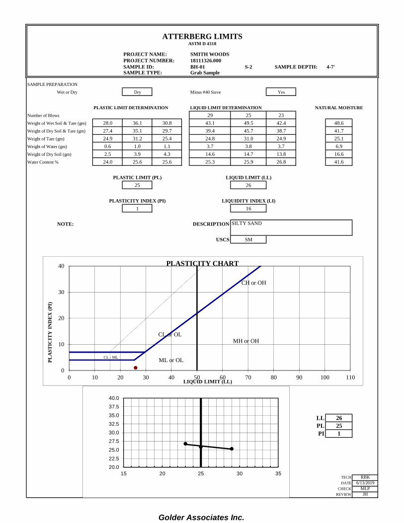
PROJECT NAME: SMITH WOODSPROJECT NUMBER: 18111326.000SAMPLE ID: BH-01 S-2 4-7'SAMPLE TYPE: Grab Sample
SAMPLE PREPARATION
Wet or Dry Dry Minus #40 Sieve Yes
PLASTIC LIMIT DETERMINATION LIQUID LIMIT DETERMINATION NATURAL MOISTURE
Number of Blows 29 25 23Weight of Wet Soil & Tare (gm) 28.0 36.1 30.8 43.1 49.5 42.4 48.6Weight of Dry Soil & Tare (gm) 27.4 35.1 29.7 39.4 45.7 38.7 41.7Weight of Tare (gm) 24.9 31.2 25.4 24.8 31.0 24.9 25.1Weight of Water (gm) 0.6 1.0 1.1 3.7 3.8 3.7 6.9Weight of Dry Soil (gm) 2.5 3.9 4.3 14.6 14.7 13.8 16.6Water Content % 24.0 25.6 25.6 25.3 25.9 26.8 41.6
PLASTIC LIMIT (PL) LIQUID LIMIT (LL)25 26
PLASTICITY INDEX (PI) LIQUIDITY INDEX (LI)1 16
NOTE: DESCRIPTION
USCS SM
LL 26PL 25PI 1
TECH RBKDATE 6/13/2019
CHECK MLPREVIEW JH
ATTERBERG LIMITS
SAMPLE DEPTH:
SILTY SAND
0
10
20
30
40
0 10 20 30 40 50 60 70 80 90 100 110
PLA
STIC
ITY
IN
DE
X (P
I)
LIQUID LIMIT (LL)
PLASTICITY CHART
CH or OH
MH or OHCL or OL
ML or OLCL - ML
20.022.5
25.0
27.530.0
32.535.0
37.540.0
15 20 25 30 35
Golder Associates Inc.

ASTM D 4318
PROJECT NAME: SMITH WOODSPROJECT NUMBER: 18111326.000SAMPLE ID: BH-04 S-1 0-3'SAMPLE TYPE: Grab Sample
SAMPLE PREPARATION
Wet or Dry Dry Minus #40 Sieve Yes
PLASTIC LIMIT DETERMINATION LIQUID LIMIT DETERMINATION NATURAL MOISTURE
Number of Blows 28 23 21Weight of Wet Soil & Tare (gm) 28.7 36.4 31.2 42.8 45.9 44.3 52.8Weight of Dry Soil & Tare (gm) 27.5 34.8 29.3 36.6 38.7 37.6 46.7Weight of Tare (gm) 24.9 31.1 25.0 24.8 25.2 25.1 31.7Weight of Water (gm) 1.2 1.6 1.9 6.2 7.2 6.7 6.1Weight of Dry Soil (gm) 2.6 3.7 4.3 11.8 13.5 12.5 15.0Water Content % 46.2 43.2 44.2 52.5 53.3 53.6 40.7
PLASTIC LIMIT (PL) LIQUID LIMIT (LL)45 53
PLASTICITY INDEX (PI)8
NOTE: DESCRIPTION
USCS SM
LL 53PL 45PI 8
TECH RBKDATE 6/13/2019
CHECK MLPREVIEW JH
ATTERBERG LIMITS
SAMPLE DEPTH:
SILTY SAND
0
10
20
30
40
0 10 20 30 40 50 60 70 80 90 100 110
PLA
STIC
ITY
IN
DE
X (P
I)
LIQUID LIMIT (LL)
PLASTICITY CHART
CH or OH
MH or OH
CL or OL
ML or OLCL - ML
45.0
47.5
50.0
52.5
55.0
15 20 25 30 35
Golder Associates Inc.
ASTM D 4318
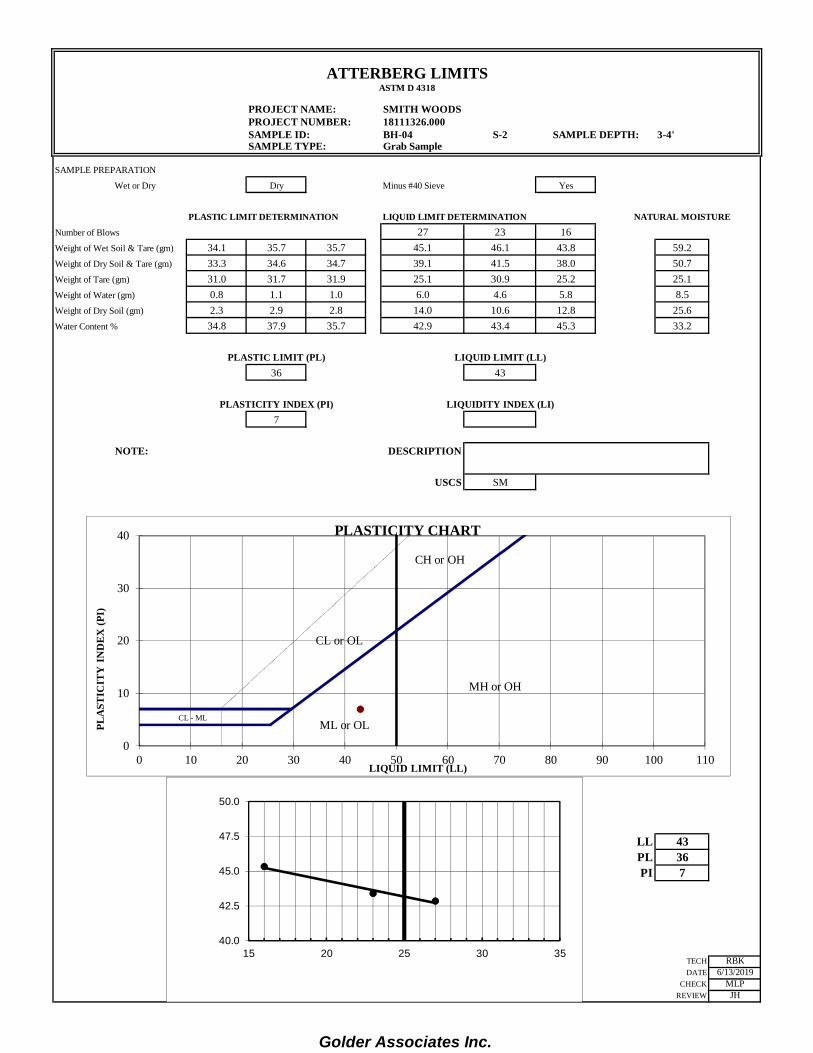
PROJECT NAME: SMITH WOODSPROJECT NUMBER: 18111326.000SAMPLE ID: BH-04 S-2 3-4'SAMPLE TYPE: Grab Sample
SAMPLE PREPARATION
Wet or Dry Dry Minus #40 Sieve Yes
PLASTIC LIMIT DETERMINATION LIQUID LIMIT DETERMINATION NATURAL MOISTURE
Number of Blows 27 23 16Weight of Wet Soil & Tare (gm) 34.1 35.7 35.7 45.1 46.1 43.8 59.2Weight of Dry Soil & Tare (gm) 33.3 34.6 34.7 39.1 41.5 38.0 50.7Weight of Tare (gm) 31.0 31.7 31.9 25.1 30.9 25.2 25.1Weight of Water (gm) 0.8 1.1 1.0 6.0 4.6 5.8 8.5Weight of Dry Soil (gm) 2.3 2.9 2.8 14.0 10.6 12.8 25.6Water Content % 34.8 37.9 35.7 42.9 43.4 45.3 33.2
PLASTIC LIMIT (PL) LIQUID LIMIT (LL)36 43
PLASTICITY INDEX (PI) LIQUIDITY INDEX (LI)7
NOTE: DESCRIPTION
USCS SM
LL 43PL 36PI 7
TECH RBKDATE 6/13/2019
CHECK MLPREVIEW JH
ATTERBERG LIMITS
SAMPLE DEPTH:
0
10
20
30
40
0 10 20 30 40 50 60 70 80 90 100 110
PLA
STIC
ITY
IN
DE
X (P
I)
LIQUID LIMIT (LL)
PLASTICITY CHART
CH or OH
MH or OH
CL or OL
ML or OLCL - ML
40.0
42.5
45.0
47.5
50.0
15 20 25 30 35
Golder Associates Inc.