Embed Size (px)
Citation preview
Romanian Journal of Morphology and Embryology 2006, 47(2):181–186
CAD method for three-dimensional model of the tibia bone and study of stresses
using the finite element method DANIELA TARNIŢĂ1), D. POPA1), D. N. TARNIŢĂ2), D. GRECU3)
1)Department of Applied Mechanics, Faculty of Mechanics, University of Craiova
2)Department of Anatomy 3)Department of Orthopedics
University of Medicine and Pharmacy of Craiova
Abstract In the real life, the leg and its skeleton are supposed at the most diverse stresses. It is known that the human bone is one of the most important natural composite materials. The paper presents a method of study and the steps to obtain the virtual bones of the human body, method applied to tibia bone. For that purpose was used a CAD parametric software which permits to define models with a high level of complexity. To obtain the bone cross sections of the tibia bone a Computer Tomograph was used. The obtained 3D model is studied using the finite element method, taking into consideration the real structure of the bone and the mechanical characteristics of cortical and spongy, and we can obtain the stresses distribution for different solicitations. Keywords: three-dimensional model of tibia bone, stress distribution, finite element method.
Introduction
The research theme, presented in this paper, it was a part of a large subject of study, which attracts the knowledge from different fields (anatomy, surgical techniques, orthopedics, mechanics, bio-mechanisms, computer science, technical graphics, and computer-aided design).
The subject of this paper permits the cooperation between many researchers which activate in different fields and which have the capacity to develop informational methods and technologies to solve difficult problems given by the complexity of the scientifically target.
The knee joint is an important joint from the human locomotion system and it is composed of bones, ligaments, tendons and cartilages. From such reason, scientifically studies are very difficult to realize because the knee is the most complex joint in the human body, almost they are made in a statically system.
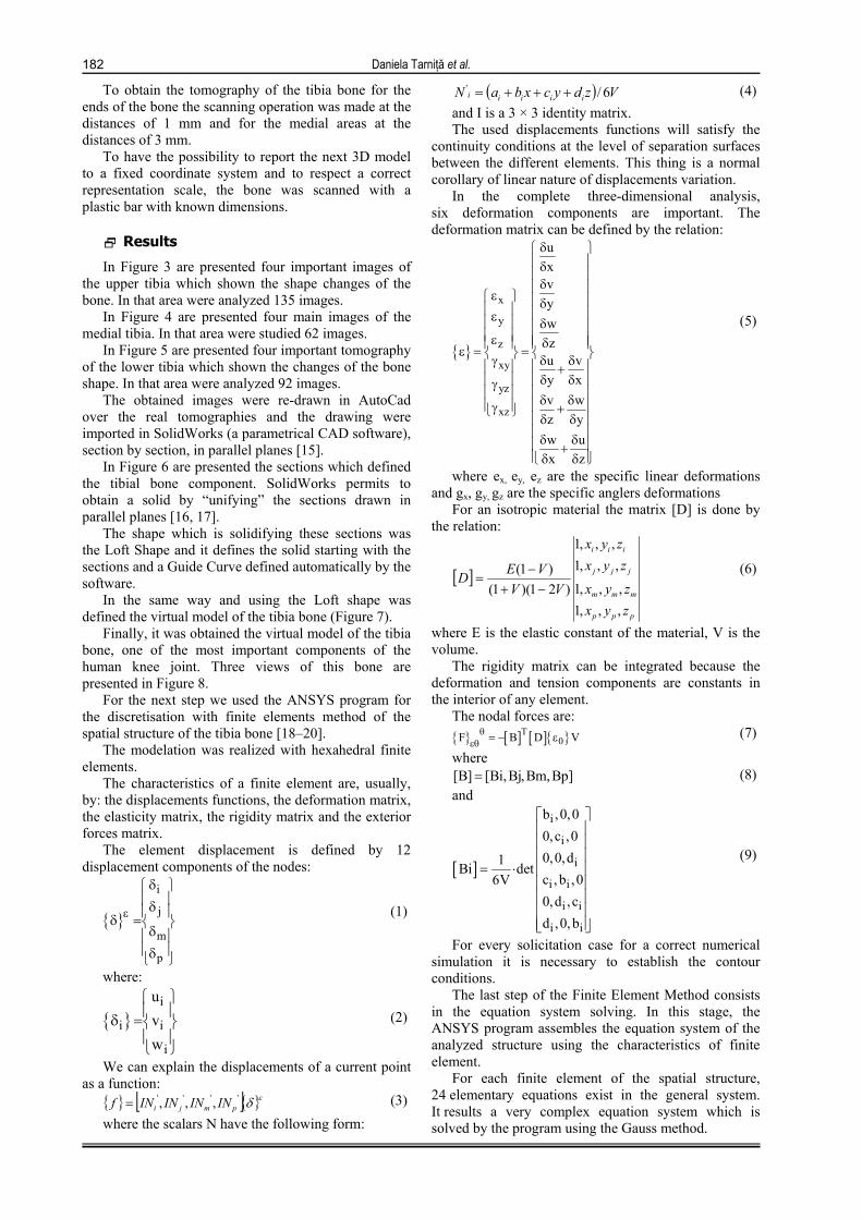
The knee has ligaments, tendons, bones, menisci and cartilages like the main components (Figure 1).
A number of risk factors for stress fracture have been identified including physical fitness, external hip rotation, body height and weight, age, race, gender, muscle mass, motivation, footwear, smoking, and family history of osteoporosis [1–3].
One of the best predictors of stress fracture risk is bone geometry. Specifically, having a narrow (i.e., more slender) tibia relative to body mass has been shown to be a major predictor of stress fracture risk and fragility in male military recruits, and male athletes [1, 4–6].
Stress fractures may be pronounced in individuals with more slender bones because smaller bone size is thought to lead to higher tissue-level stresses and thus increased damage accumulation [1, 2].
However, this postulate is based on the assumption that all bones are constructed in equivalent manners, and the contribution of variable tissue-level mechanical properties to stress fracture incidence has not been explored. Stress fractures have been reported in the ribs, hip, pine, and metatarsals, but vigorous weight-bearing activities, such as running and jogging, commonly lead to stress fractures of the lower extremities, especially the tibia [5].
Mineral content has been shown to be positively correlated with tissue stiffness and strength [7].
The geometry's and mechanical properties' natural variability of the bone system from one to the other is a big problem which makes real difficulties in the biomechanical researches [8–10].
Biological processes that attempt to repair the damage may further weaken the tissue because the increased resorption results in increased tissue porosity [11, 12].
The dimensions, form, mechanical properties, elastic constants, physical constants of the bone are different from one to the other. They depend on: age, sex, height, profession etc. [13, 14].
The geometrical aspects of the bone systems modeling are dominated by the necessity of using some spatial models because most of the bone elements have complicated geometrical forms in space.
Material and methods
To obtain the bone cross sections was used a PHILIPS AURA Computer Tomograph installed in the Emergency County Hospital of Craiova (Figure 2) has been used. We have used tibia bones from dead persons, kept in the Laboratory of Anatomy from the University of Medicine and Pharmacy of Craiova.
Daniela Tarniţă et al.
182
To obtain the tomography of the tibia bone for the ends of the bone the scanning operation was made at the distances of 1 mm and for the medial areas at the distances of 3 mm.
To have the possibility to report the next 3D model to a fixed coordinate system and to respect a correct representation scale, the bone was scanned with a plastic bar with known dimensions.
Results
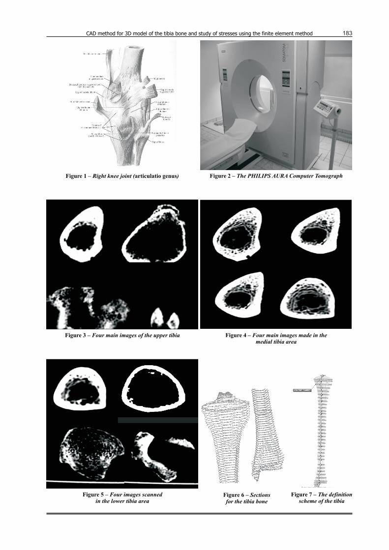
In Figure 3 are presented four important images of the upper tibia which shown the shape changes of the bone. In that area were analyzed 135 images.
In Figure 4 are presented four main images of the medial tibia. In that area were studied 62 images.
In Figure 5 are presented four important tomography of the lower tibia which shown the changes of the bone shape. In that area were analyzed 92 images.
The obtained images were re-drawn in AutoCad over the real tomographies and the drawing were imported in SolidWorks (a parametrical CAD software), section by section, in parallel planes [15].
In Figure 6 are presented the sections which defined the tibial bone component. SolidWorks permits to obtain a solid by “unifying” the sections drawn in parallel planes [16, 17].
The shape which is solidifying these sections was the Loft Shape and it defines the solid starting with the sections and a Guide Curve defined automatically by the software.
In the same way and using the Loft shape was defined the virtual model of the tibia bone (Figure 7).
Finally, it was obtained the virtual model of the tibia bone, one of the most important components of the human knee joint. Three views of this bone are presented in Figure 8.
For the next step we used the ANSYS program for the discretisation with finite elements method of the spatial structure of the tibia bone [18–20].
The modelation was realized with hexahedral finite elements.
The characteristics of a finite element are, usually, by: the displacements functions, the deformation matrix, the elasticity matrix, the rigidity matrix and the exterior forces matrix.
The element displacement is defined by 12 displacement components of the nodes:
{ }
i
j
m
p
ε
δ δ δ = δ δ
(1)
where:
{ }i
i i
i
uvw
δ =
(2)
We can explain the displacements of a current point as a function:
{ } [ ]{ }εδ'''' ,,, pmji ININININf = (3) where the scalars N have the following form:
( ) VzdycxbaN iiiii 6/' +++= (4) and I is a 3 × 3 identity matrix. The used displacements functions will satisfy the
continuity conditions at the level of separation surfaces between the different elements. This thing is a normal corollary of linear nature of displacements variation.
In the complete three-dimensional analysis, six deformation components are important. The deformation matrix can be defined by the relation:
{ }
x
y
z
xy
yz
xz
uxvywzu vy xv wz yw ux z
δ δ δ ε δ ε δ
ε δ ε = = δ δγ +δ δ γ
δ δ γ + δ δ δ δ + δ δ
(5)
where ex, ey, ez are the specific linear deformations and gx, gy, gz are the specific anglers deformations
For an isotropic material the matrix [D] is done by the relation:
[ ]
ppp
mmm
jjj
iii
zyxzyx
zyxzyx
VVVED
,,,1,,,1
,,,1,,,1
)21)(1()1(
−+−
= (6)
where E is the elastic constant of the material, V is the volume.
The rigidity matrix can be integrated because the deformation and tension components are constants in the interior of any element.
The nodal forces are: { } [ ] [ ]{ }T
0F B D Vθεθ = − ε (7)
where [B] [Bi,Bj,Bm,Bp]= (8) and
[ ]
i
i
i
i i
i i
i i
b ,0,00,c ,00,0,d1Bi detc , b ,06V0,d ,cd ,0, b
= ⋅
(9)
For every solicitation case for a correct numerical simulation it is necessary to establish the contour conditions.
The last step of the Finite Element Method consists in the equation system solving. In this stage, the ANSYS program assembles the equation system of the analyzed structure using the characteristics of finite element.
For each finite element of the spatial structure, 24 elementary equations exist in the general system. It results a very complex equation system which is solved by the program using the Gauss method.
CAD method for 3D model of the tibia bone and study of stresses using the finite element method 183
Figure 1 – Right knee joint ( )articulatio genus
Figure 5 – Four images scannedin the lower tibia area
Figure 2 – The PHILIPS AURA Computer Tomograph
Figure 3 – Four main images of the upper tibia Figure 4 – Four main images made in themedial tibia area
Figure 6 – Sectionsfor the tibia bone
Figure –7 The definitionscheme of the tibia
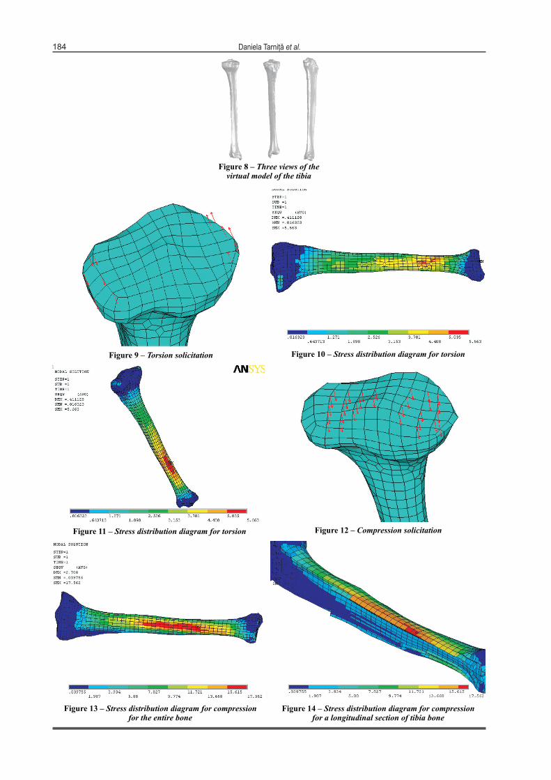
Figure 8 – Three views of thevirtual model of the tibia
184 Daniela Tarniţă et al.
Figure 11 – Stress distribution diagram for torsion Figure 12 – Compression solicitation
Figure 10 – Stress distribution diagram for torsionFigure 9 – Torsion solicitation
Figure 13 – Stress distribution diagram for compressionfor the entire bone
Figure 14 – Stress distribution diagram for compressionfor a longitudinal section of tibia bone
CAD method for 3D model of the tibia bone and study of stresses using the finite element method
185
The geometrical model was supposed at different solicitations for studying the most solicited parts of the bone which will be the possible broken parts [16, 19, 20].
In the first case, the virtual model of tibia bone was supposed to a torsion couple equal with 4.8 Nm on the top surface (Figure 9).
The bone is leaned in his inferior base. The virtual solicitation is realized with the help of two sets of forces placed on the extremities of had bone, in a perpendicular plane on the longitudinal axe of the bone.
We obtained the resultant stress distribution for the torsion solicitation for the entire bone (Figures 10 and 11).
We observe that the most solicited areas of the bone are situated in the 1/3 inferior diaphisis of the bone, where the value of section area is minim. On diagram, the maxim values are indicated by the color red, and the minim values are indicated by the color blue. The values increase from blue to red.
In second case the bone was supposed to a compression force equal with 800 N distributed on the both superiors condils (Figure 12), having the direction of the longitudinal axe of the bone. Finally, we obtained the resultant stress distribution for the compression solicitation (Figures 13 and 14).
Discussions
The last step of the Finite Element Method consists in the equation system solving. In this stage, the ANSYS program assembles the equation system of the analyzed structure using the characteristics of finite element.
For each finite element of the spatial structure, 24 elementary equations exist in the general system. It results a very complex equation system which is solved by the program using the Gauss method.
Solving the equation system leads to the determination of the principal variables which are the nodal displacements on the three directions in every node of all the finite elements. The ANSYS program uses these results for the determination of the deformations and stresses which appear in the analyzed structure.
We have taken into consideration the real structure of the human bone. We know that the bone is one of the most important natural composite materials. The body of the tibia bone is formed by a compact bone tissue cylinder all pierced by a central channel called the medullar channel. The ends of the bone are formed by a thin layer made outside by a compact bone substance, and inside by a spongy mass.
The work hypotheses are: a) Even though the material of the bone is an-
isotropic and not homogeneous, in the modeling, the bone was considered homogeneous and isotropic, for a zone of solicitation that does not exceed certain limits.
b) The bone is made by two kinds of materials, compact and spongy, like a composite material.
c) The average values considered for the longitudinal modulus of elasticity, E, are: 20.000 N/mm2 for the compact bone, situated in the exterior zone of the bone
and 2 N/mm2 for the spongy bone, situated in the interior zone. The value of the coefficient for the transversal contraction of Poisson was 0.3.
d) The virtual central channel is realized in accordance with the obtained tomographies, so the complex spatial structure is assured.
In both of the analyzed cases (torsion and compression) the results were obtained using the Von Mises theory and the values are presented in N/mm2 or MPa (Mega Pascals). On the value scale, the higher values of stresses are indicated by red color and the lower values are indicated by blue color. The values increase from blue to red.
It can be observed that even the solicitations are uniform; the repartitions of stresses along the bone are not uniform. This thing is the result of the complex form of the tibia. The lower values are found at the extremities of the bone and the highest values are found in a limited area on the anterior zone.
It can be also observed that the maximal values are recorded in the 1/3 inferior diaphisis of the bone, where the value of section area is minim. In figure 14 it can be observed the bone structure.
Conclusions
In this paper we present and discuss the results obtained with a three-dimensional finite element model of the tibia human bone corresponding to different external solicitations.
The three-dimensional finite element model has been constructed based on Computer Tomograph scans of a tibia specimen.
The use of the computer tomograph for the sectioning of the bone increases the precision of the model.
The obtained three-dimensional model of tibia bone uses parameters completely, so it can be adapted by modifying any specific dimensions.
The virtual model of the bone can be supposed at different solicitations, and using the finite element method and ANSYS_5 programs can be studied the stresses, and also, the displacements distribution for entire bone or for a longitudinal section of bone.
From the diagram analysis we observe that the highest values of stresses occur in the curvature zone of the bone situated in the diaphisar area that will become the future fracture zone.
The observations made by studying 34 cases of real fractures caused by torsion and compression and also made by the testing of 11 tibia bones confirms that the most frequent place of fracture is situated at the level of 1/3 distal of tibial diaphisis. For testing the bone, we used the EDZ20 machine from the Laboratory of Strength Materials, Faculty of Mechanics, University of Craiova.
These conclusions confirm the fidelity and the accuracy of virtual model, so this model can be used in other similar researches for other different kinds of solicitations.
The scientific results could be introduced in studies in the fields of robotics, biomechanics, and applications of the smart materials in the medical field.
Daniela Tarniţă et al.
186
References [1] TOMMASINI S. M., NASSER P., SCHAFFLER M. B., JEPSEN K. J.,
Relationship between bone morphology and bone quality in male tibias: implications for stress fracture risk, J Bone Miner Res, 2005, 20:1372–1380.
[2] BENNELL K., MATHESON G., MEEUWISSE W., BRUKNER P., Risk factors for stress fractures, Sports Med, 1999, 28:91–122.
[3] GILADI M., MILGROM C., SIMKIN A., DANON Y., Stress fractures. Identifiable risk factors, Am J Sports Med, 1991, 19:647–652.
[4] MILGROM C., GILADI M., SIMKIN A. et al., The area moment of inertia of the tibia: A risk factor for stress fractures, J Biomech, 1989, 22:1243–1248.
[5] GILADI M., MILGROM C., SIMKIN A. et al., Stress fractures and tibial bone width. A risk factor, J Bone Joint Surg Br, 1987, 69:326–329.
[6] CROSSLEY K., BENNELL K. L., WRIGLEY T., OAKES B. W., Ground reaction forces, bone characteristics, and tibial stress fracture in male runners, Med Sci Sports Exerc, 1999, 31:1088–1093.
[7] CURREY J. D., Effects of differences in mineralization on the mechanical properties of bone, Philos Trans R Soc Lond B Biol Sci, 1984, 304:509–518.
[8] MILLER G. J., PURKEY W. W. JR., The geometric properties of paired human tibiae, J Biomech, 1980, 13:1–8.
[9] BURSTEIN A. H., REILLY D. T., MARTENS M., Aging of bone tissue: Mechanical properties, J Bone Joint Surg Am, 1976, 58:82–86.
[10] EVANS F. G., Age changes in mechanical properties and histology of human compact bone, Yearb Phys Anthropol, 1976, 20:1361–1372.
[11] FERRETTI J. L., COINTRY G. R., CAPOZZA R. F., FROST H. M., Bone mass, bone strength, muscle-bone interactions, osteopenias and osteoporoses, Mech Ageing Dev, 2003, 124:269–279.
[12] SCHAFFLER M. B., BURR D. B., Stiffness of compact bone: Effects of porosity and density, J Biomech, 1988, 21:13–16.
[13] LANYON L. E., HAMPSON W. G., GOODSHIP A. E., SHAH J. S., Bone deformation recorded in vivo from strain gauges attached to the human tibial shaft, Acta Orthop Scand, 1975, 46:256–268.
[14] BURR D. B., MILGROM C., FYHRIE D. et al., In vivo measurement of human tibial strains during vigorous activity, Bone, 1996, 18:405–410.
[15] ***, SolidWorks 98 Plus User’s Guide, SolidWorks Corporation, U.S.A., 1998.
[16] TARNIŢĂ DANIELA, TARNIŢĂ D. N., CERNĂIANU E., The Method of Finit Element applied at study of bending stress and displacements of metacarpi bone, International Conference on Composite Engineering, ICCE/3, New Orleans, 1996.
[17] POPA D., TARNIŢĂ D. N., TARNIŢĂ DANIELA, The generation of the three-dimensional model of the human knee joint, Rom J Morphol Embryol, 2005, 46(4):279–282.
[18] MARCHOUK G., Introduction aux methods des elements finis, Editions Mir, Moscou, 1985, 20–75.
[19] TARNIŢĂ DANIELA, TARNIŢĂ D. N, CERNĂIANU E., The Method of Finite Element applied at study of stress and displacements of hand bone, The XVth International Congress Danubia–Adria, Bertinoro, Italy, 1998, 125–126.
[20] TARNIŢĂ DANIELA, TARNIŢĂ D. N., POPA D. et al., The Method of Finite Element applied to the study of stress distribution of tibia, International Symposium “Biomaterials and Biomechanics”, Essen, Germany, September 21st–23rd, 2005, 165.
Mailing address Daniela Tarniţă, Professor, Eng., PhD, Department of Applied Mechanics, Faculty of Mechanics, University of Craiova, 165 Avenue Calea Bucureşti, 200 620 Craiova, Romania; Phone +40251–544 621, Fax +40251–454 503, E-mail: [email protected] Received: October 5th, 2006
Accepted: October 25th, 2006