Embed Size (px)
Citation preview
AD-A251 180 AD
ECHNI CA-Tr e p0o r tL
USA-BRDEC-TR // 2523
Air Conditioner RequirementsValidation Review of the
Divarty Computer Group of theFire Direction Center, Artillery
(OL-48B/GSG 1O(V)), or TACFIREby
DG;regory F. Brainard , TiC fReport Date JH10923May 1992
D~tflbton unlimited; aPPrOved for public release
92-15062United States Army
Betvoir Research, Development and Engineering Center4Fort BeNvOl., Virginia 22060-6606
92 f5 W 0' ,
Destroy this report when it is no longer needed.Do not return it to the originator.
The citation in this report of trade names ofcommercially available products does not constituteofficial endorsement or approval of the use of suchproducts.
Form ApprovedREPORT DOCUMENTATION PAGE OMB No. 0 7WI U
Pubc reorw h~fdem 1wt fis w & d inkmmaWn ,is eiab bD arwapl I hour pe mrm.o ,ndudmg A*e Win kl rare"n Wt4cl*s. Wearchig wswq deam swauts 90rog Wd MWL>o de au rn<W,
HftWs SwvM Dirwi ol WarmAn OWam aid Rwwf 1215 JOIN 0"e How,,r. &At 1204. M IrW. VA 2=4 WW~ ID Ow0" of Mffall~ftt a, d9 Raegow Prq .{704.0 S.Wat nm. DC 2M :.
1. AGENCY USE ONLY (Lw blank) 2. REPORT DATE 3. REPORT TYPE AND DATES COVERED
May 1992 Final
4. TITLE AND SUBTITLE 5. FUNDING NUMBERS
Air Conditioner Requirements Validation Review of the Divarty Computer Group ofthe Fire Direction Center, Artillery (OL-48B/GSGI0(V)), or TACFIRE (U)
S. AUTHOR(S)
Gregory F. Brainard; technical and administrative input from Andrew A.Thompson, James P. Lucas, and the Systems Assessment Team
7. PERFORMING ORGANIZATION NAME(S) AND ADDRESS(ES) 8. PERFORMING ORGANIZATIONBelvoir Research, Development & Engineering Center REPORT NUMERLogistics Equipment Division 2523Environmental Control and Systems Support DivisionFort Belvoir, VA 22060-5606
9. SPONSORING/MONITORING AGENCY NAME(S) AND ADDRESS(ES) 10. SPONSORING/MONrrORINGAGENCY REPORT NUMBER
11. SUPPLEMENTARY NOTES
POC: Gregory F. Brainard, (703) 704-2634
12. oISTRIBUTONAVYLABIJTY STATEMENT 12bL DISTRIBUTION CODE
Distribution unlimited; approved for public release.
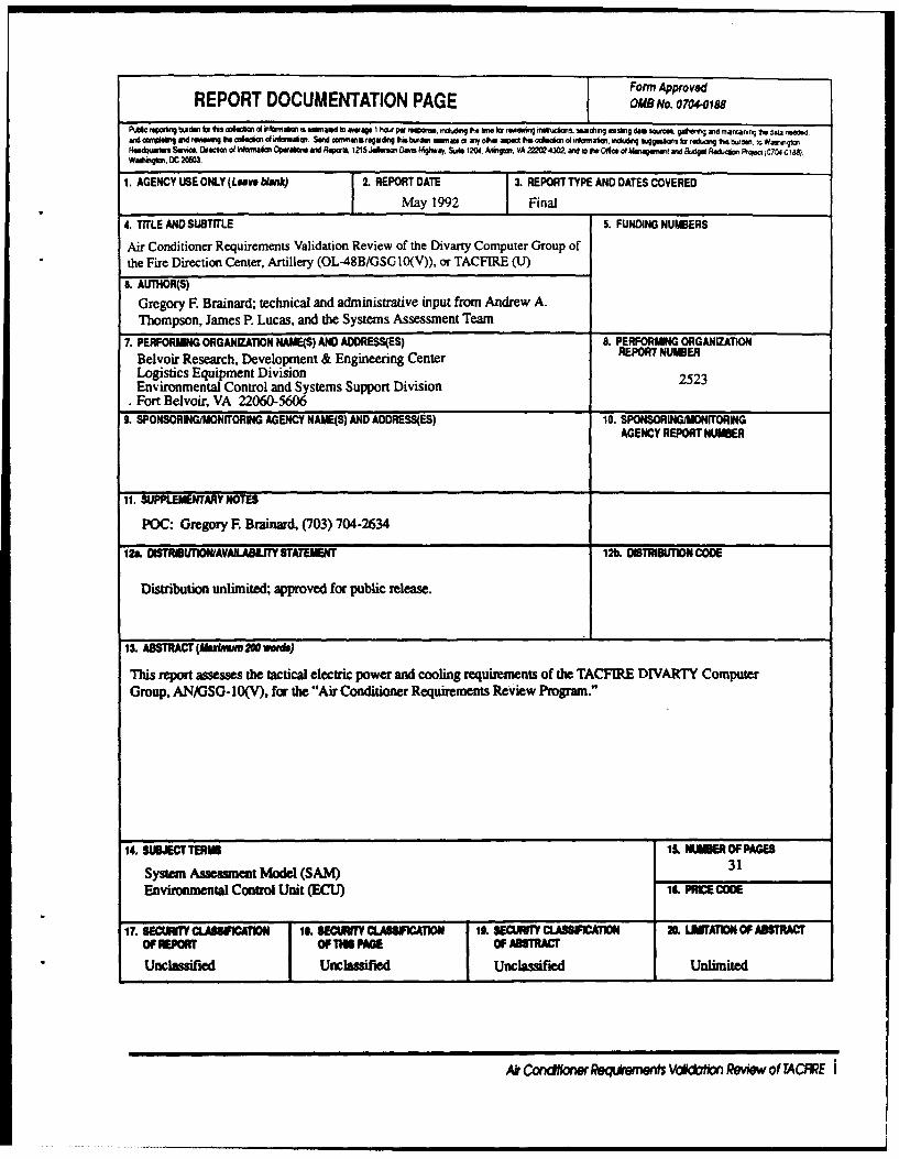
13. ABSTRACT (Abxnm 200 words)
This report assesses the tactical electric power and cooling requirements of the TACFIRE DIVARTY ComputerGroup, AN/GSG-10(V), for the "Air Conditioner Requirements Review Program."
14. SIBEC l 1ER IMER OF PAG
System Assessment Model (SAM) 31
Enviromental Control Unit (ECU) PRICE CODE
17. SEWrRfICLhhUICATION 18. SECunT Y CLASSICATION it SECURITY CLASSIICATION 2. LAMATON OF ABSTRACTOF REPORT OF1"IS WE OF ABSTRACT
U eUnclassified Unclassified Unlimited
Ar Cndfloew Reqdrkem Vtdaon Review of TACFE i
Report Number 2523
Air Conditioner RequirementsValidation Review of the
Divarty Computer Group of theFire Direction Center, Artillery
(OL-48B/GSG10(V)), or TACFIRE
byGregory F. Brainard
US Army Belvoir RD&E CenterFort Belvoir, Virginia 22060-5606
May 1992
Distribution unlimited; approved for public release.
Akr Ca e Req~eM Vo Reiw of TACFIRE iii
Table of Contents
Page
Section I Background ....................................................... I
Section 11 Approach ..................................................... 2
Section III System Description ...................................... 3
Section IV Discussion .................................................... 4
Section V Findings ............................................................. 8
Appendix Special SSDC Report SR 90-156 Air ConditionerRequirements Review, Power ConsumingEquipment Inventory, Fire Direction Center,Artillery, November 8, 1990
Tables
1 TACFIRE Equipment Power Demands ................. 5
2 SAM Model Data ...................................................... 6
Figure of TACFIRE Cooling Requirements, 900F Internal ........... 7
Aooession For
DT,, 7 T3 0jp,-c'ne
By-
D i tr_.but-i-n/ -----AvailabllitY Codes
Mst o ReviwV
Air Ca fi e eqtdwents Vokdohn Review of TACRRE V
Section I
Background
The U. S. Army's Troop Support Command (TROSCOM) and Trainingand Doctrine Command (TRADOC) initiated the "Air Conditioner
Requirements Review Program" to establish requirements for a newgeneration of environmental control equipment. TRADOC's OrdnanceSchool; TROSCOM's Special Programs Management Office; and BelvoirResearch, Development and Engineering Center (BRDEC) SystemsAssessment Team were the program's primary participants. TheSystems Assessment Team was directed to assess the electric powerand cooling requirements of selected Army systems. To assist in this
effort, a Special Sample Data Collection (SSDC) Project was establishedunder the auspices of the TROSCOM Sample Data Collection Program.The SSDC Project Inventories each system, paves the way for theassessment, and conducts operator interviews regarding the
effectiveness of existing electric power and cooling equipment.Systems to be assessed include: DAS-3, MSE, TACMIS, FAADS, SICPS,and Patriot.
Ak C&tl wRmn Vdo*i Reew of TACRRE 1
Section II
Approach
It is necessary to account for electrical power demand when
determining the cooling load of a system. This process involves three
steps:
First, all power consuming equipment in the system's shelter must be
inventoried. This includes collecting the manufacturer's nameplate
data and inspecting manuals for each item.
Second, the system's power consumption must be measured whileequipment items, groups, and the entire system are powered-up and
powered-down. From this data, the power demand of each piece ofequipment and a predicted maximum system power demand can be
derived. This technique includes power conditioner losses with thesupported equipment's power demand.
Finally, the shelter's thermal characteristics and personnel and tactical
requirements must be entered into the Shelter Systems Assessment
Model (SAM). The computer model can then determine cooling loads
and Environmental Control Unit (ECL) suitability under hypothetical
ambient conditions. When test conditions allow, the ECU needs should
be validated using temperature data taken during the test and byinterviewing experienced system operators.
2 AkCondtbonReqikementsVoadoffciRevlewofTACRRE
Section III
System Description
TACFIRE supports the artillery mission by:
* Collecting target information from forward observers.
* Calculating optimum projectile type(s) and trajectory(ies) usingtopological, weather, and strategic information.
* Transmitting information to decision makers and artillery
operators.
The TACFIRE DIVARTY Computer Group, Fire Direction Center, Artillery,Model OL-48B, AN/GSG-10(V) (Line Item Number F55750, National StockNumber 7010-01-017-7040) is housed in an S-280 shelter mounted on a5 ton truck. Field power is provided by a 15 kW, 400 Hz trailer-mounted
generator set (Line Item Number G36074). Cooling is provided by an18,000 BTUH horizontal air conditioner (Line Item Number A24575).
TACFIRE's electronic equipment includes communications, datarecording and processing, and graphical mapping capabilities (see
page 4 of Appendix). Three soldiers operate the system.
Air Co w Reqkemnts Vacda on Review of TACRRE 3
Section IVDiscussion
An inventory of TACFRRE was performed and each piece of power
consuming equipment was listed as a column heading on the PowerMeasurement L ad Configuration form (see Figure 2 of Appendix).This form documents the switch position for each equipment item at
each step of the test sequence. The test began with all equipment
except the heater on or in stand-by mode. The test team took powerconsumption readings at the power source while operators switchedoff equipment in sequence. The power readings were entered in thePower Generator Performance form (see Figure 3 of Appendix). Thisform records the load on each phase of the generator for each step inthe test sequence.
The power consumed by each item, including associated power
conditioning losses (see Table 1), is derived from the change in totalpower as the item is switched off. The power consumption data listedon Table I is grouped into several subcategories.
The first category, "Total Measured Power Demand in OperationalMode," refers to equipment that was tested at its full operational
capacity. The second category, "Measured Power Demand in Stand-ByMode," refers to equipment for which test conditions preventedmaximum load operation. For example, a plotter cannot operateunless a job Is available to run. Those subtotals are then added to
achieve "Total Measured Power Demand Internal Load," which is theelectric power which the ECU capacity must compensate for tomaintain the desired internal temperature. The final total, "TotalEstimated Generator Load," Includes the electric load which does not
contribute to the cooling requirement.
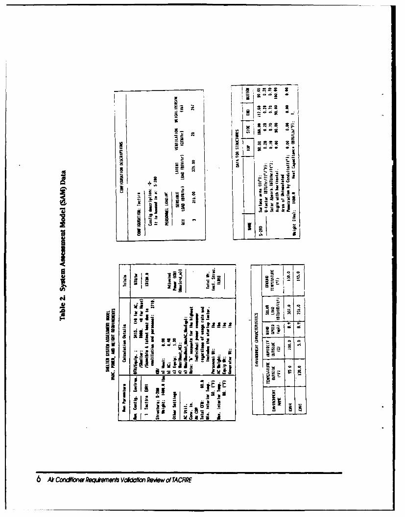
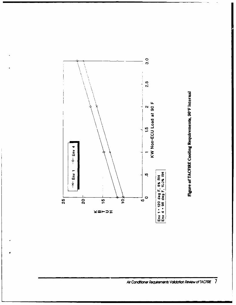
Power consuming Items and their respective power demand were used
as input for several runs of the SAM (see Table 2 on page 6). Internal
temperature was selected to satisfy Human Engineering M1L-STD-1472considerations (900F). Internal humidity was limited to 60%. Desert
conditions (environment 1, AR 70-38), tropic conditions (environment4), and equipment power use of 0 through 10 kW were analyzed.Assumptions used In the computer analysis are found In the figure on
page 7.
4 A C gdn Ren r VoklaficnReewofTACFRE
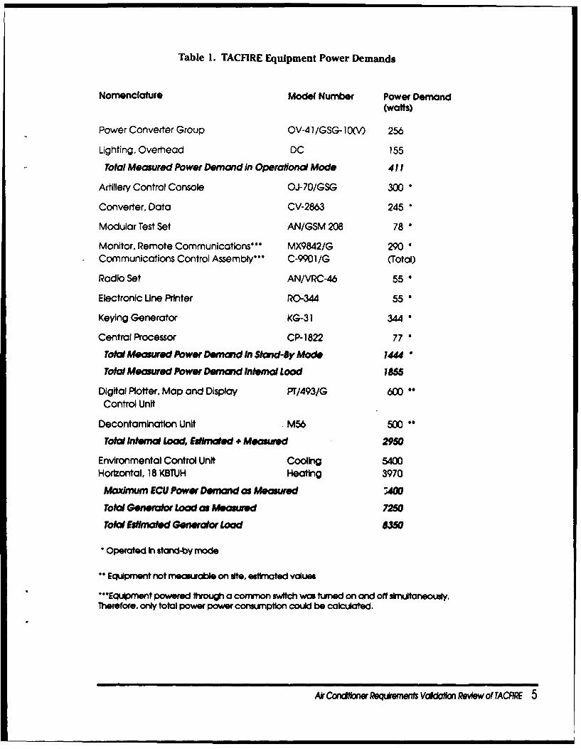
Table 1. TACFIRE Equipment Power Demands
Nomenclature Model Number Power Demand(watts)
Power Converter Group OV-41/GSG-10(V) 256
Lighting, Overhead DC 155
Total Measured Power Demand in Operaiond Mode 411
Artillery Control Console OJ-70/GSG 300
Converter, Data CV-2863 245 *
Modular Test Set AN/GSM 208 78 &
Monitor, Remote Communications' MX9842/G 290
Communications Control Assembly'" C-9901/G (Total)
Radio Set AN/VRC-46 55
Electronic Une Printer R(0-344 55
Keying Generator KG-31 344*
Central Processor CP- 1822 77
Total Measured Power Demand In Stand-By Mode 1444
Total Measured Power Demand Internal Load 1855
Digital Plotter. Map and Display PT/493/G 60*Control Unit
Decontamination Unit M56 500
Total Internal Load, Estmated + Measured 2950
Environmental Control Unit Cooling 5400Horizontal, 18 KBTUH Heating 3970
Maximum ECU Power Demand as Measured ;4O
Total Generator Load as Measured 7250
Total Estinated Generator Load 8350
Operated In siand-by mode
Equipment not measurable on site, estimated values
*Equipment powered through a common switch was turned on and off simultaneously.Therefore, only total power power consurnptlon could be calculated.
Ak CndWnr Reqemewn VcaaIofin ReAew of TACRRE 5
I i j0 0 0 .J
L
t t
Ak ~ ~ ~ ~ ~ ~ ; 3aowRqw*vkw eo fT
___ ___ __ ___ ___ __ ___ __ 0
C6,
00
0V 0)
M jot* 03
to Ul 0U '
N00
-V-
W W
Arcaww~e~wn&vak~mftwofTcR1
Section V
Findings
TACF1RE power demand, with all available equipment operating,
measured 7.25 kW, including 5.4 kW for ECUs and 1.85 kW forequipment. In this configuration, a 10 kW generator set will supportthe system. However, previous studies show that the TACFIRE systemis sensitive to the voltage drop caused by the environmental controlunit starting up and cycling. Therefore, the larger 15 kW generator setis appropriate for the system. The 18,000 BTUH air conditionerprovides the necessary cooling for TACFIRE's electronic equipment.
There is an effort underway at Fort Belvoir to develop a new family of
Multiple Power Input (MPI) ECUs. The power drawn by the MPI ECUswill "ramp up," significantly reducing the power line transients caused
by the current family of ECUs. TACFIRE may reduce its logisticalburden by using an MPI ECU and a 10 kW generator instead of the
current 15 kW generator.
8 At cSaVtoRoqwntVRkWn R ofTACRRE
Appendix
(ICOBRO,
SR90-156
November 8,1990
Special Report
Air Conditioner Requirements ReviewPower Consuming Equipment InventoryFire Direction Center, Artillery
PREPARED FOR:
U.S. Army Belvoir Researh,Development & Engineering CenterAttention: STRBE-FEAFort Belvoir, Virginia 22060
PREPARED BY:
COBRO CorporationSuite 850, North Tower7799 Leesburg PikeFalls Church, Virginia 22043
Wkle IM, Nolb Tower ? M'N9 Labarg Pll. a Falls Chuch, VA 22043 * (71) 443-33M * (Fax) (73) 4440
Appendx to Air Conditioner Requirements VWalon Review of TACFIRE
TABLE OF CONTENTS
Pag~e
Introduction ........... ........................... 1
Program Overview ........... ....................... I
Data Collection Infrastructure ....... ................. 1
Data Objectives ............. ....................... 2
Collection Methodology .......... ..................... 2
Fower Analysis ............ ......................... 3
CTASC II Description ........... ...................... 3
CTASC II Power Consuming Equipment Inventory ..... .......... 3
Debriefing ............................... 5
List of Figures
Fi-ure Title Paae
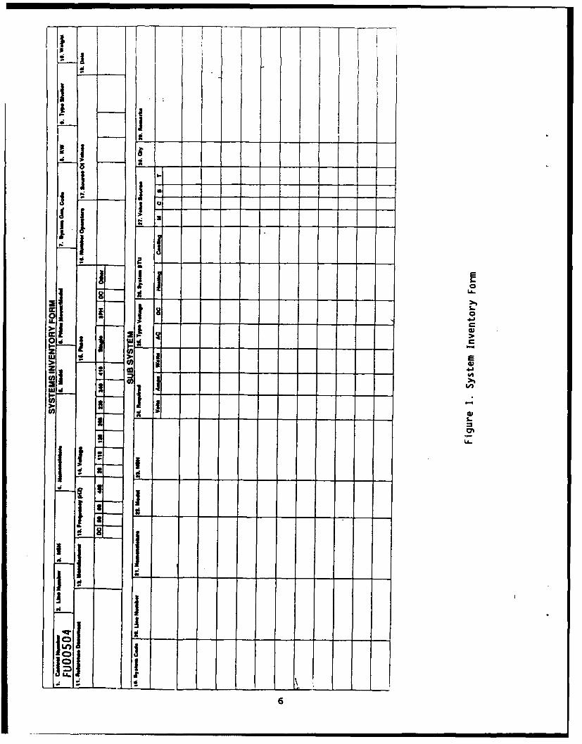
1 System Inventory Frm ....... ............... 6
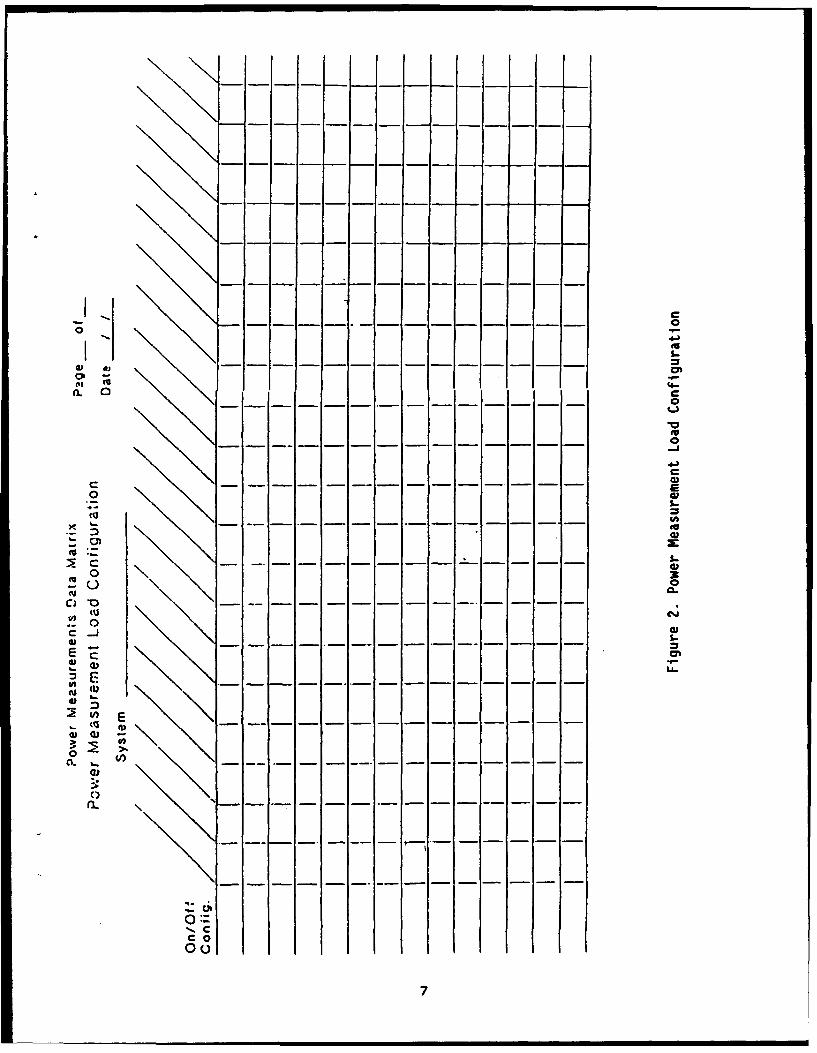
2 Power Measurement Load Configuration Form .. ..... 7
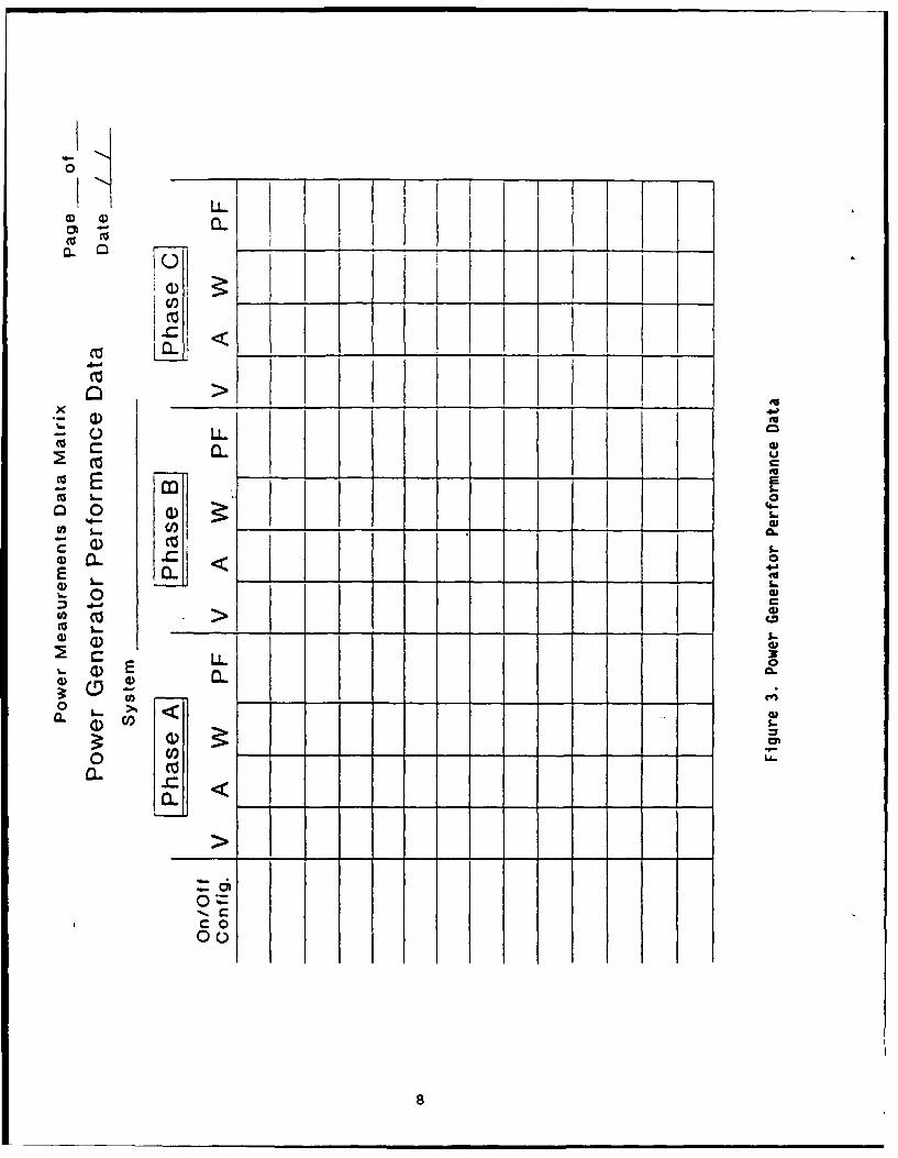
3 Power Generator Performance Data Form ... ....... 8
SPECIAL REPORT
AIR CONDITIONER REQUIREMENTS REVIEW
TACFIRE ASSESSMENT
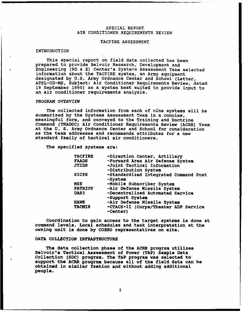
INTRODUCTION
This special report on field data collected has beenprepared to provide Belvoir Research, Development andEngineering (RD & E) Center's Systers Assessment Team selectedinformation about the TACFIRE system, an Army equipmentdesignated by U.S. Army Ordnance Center and School (Letter,ATSL-CD-MS, Subject: Air Conditioner Requirements Review, dated19 September 1990) as a system best suited to provide input toan air conditioner requirements analysis.
PROGRAM OVERVIEW
The collected information from each of nine systems will besummarized by the Systems Assessment Team in a concise,meaningful form, and conveyed to the Training and DoctrineCommand (TRADOC) Air Conditioner Requirements Review (ACRR) Teamat the U. S. Army Ordnance Center and School for considerationas the team addresses and recommends attributes for a newstandard family of tactical air conditioners.
The specified systems are:
TACFIRE -Direction Center, ArtilleryFAADS -Forward Area Air Defense SystemJTIDS -Joint Tactical Information
-Distribution SystemSICPS -Standardized Integrated Command Post
-SystemMSE -Mobile Subscriber SystemPATRIOT -Air Defense Missile SystemDAS3 -Decentralized Automated Service
-Support SystemHAWK -Air Defense Missile SystemTACMIS -CTACS-II (Corps/Theater ADP Service
-Center)
Coordination to gain access to the target systems is done atcommand levels. Local schedules and task interpretation at theowning unit is done by COBRO representatives on site.
DATA COLLECTION INFRASTRUCTURE
The data collection phase of the ACRR program utilizesBelvoir's Tactical Assessment of Power (TAP) Sample DataCollection (SDC) program. The TAP program was selected tosupport the ACRR program because all of the field data can beobtained in similar fashion and without adding additionalpeople.
"" ' ! |1
TAP is supported in the field using the contracted supportinfrastructure for SDC. COBRO Corporation provides the supportto TAP and to ACRR through its offices at Fort Belvoir, FortBragg, Fort Hood, and others, depending upon where the targetsystems can be located.
DATA OBJECTIVES
The collection is focussed on the equipment listed underProgram Overview. The purpose is to develop detailed data ontactical power consumers, tactical shelters, tactical airconditioners mounted on the tactical shelters, shelterizedsystem crew staffing, system environmental capability, systemoperating profiles, and crew training and experience.
COLLECTION METHODOLOGY
Data are collected on site by a team of people organized toperform a subsystem inventory, conduct a controlled, power-upprocedure, measure operating and environmental parameters, anddebrief operators about their training on the system, theirfield experience with the system, and the system's operatingmodes.
The data collection field team consists of a SeniorTechnician and an Engineer from the Systems Assessment Team atFort Belvoir. A Field Monitor from a COBRO Corporation fieldoffice and the COBRO Senior Technical Analyst for the COBRO TAPSDC Program at Fort Belvoir completes the team.
At the field site the team accomplishes the following:
Assistance of the system operator(s) is solicited toidentify the separate power consuming subsystems/componentsof the system housed in the shelter. The inventory data areposted to the Power Using Inventory form (Figure 1).
The interrelationships and power supply lash-up is reviewedas a basis for developing a measurement test plan.Initially, the plan is tentative and can be sensitive to theunexpected. The plan is modified as necessary and is postedto the Power Measurement Load Configuration form (Figure 2)as a sequence of power-up events. Results are posted byinput power phase (A, B, and D) to the Power GeneratorPerformance Data form (Figure 3).
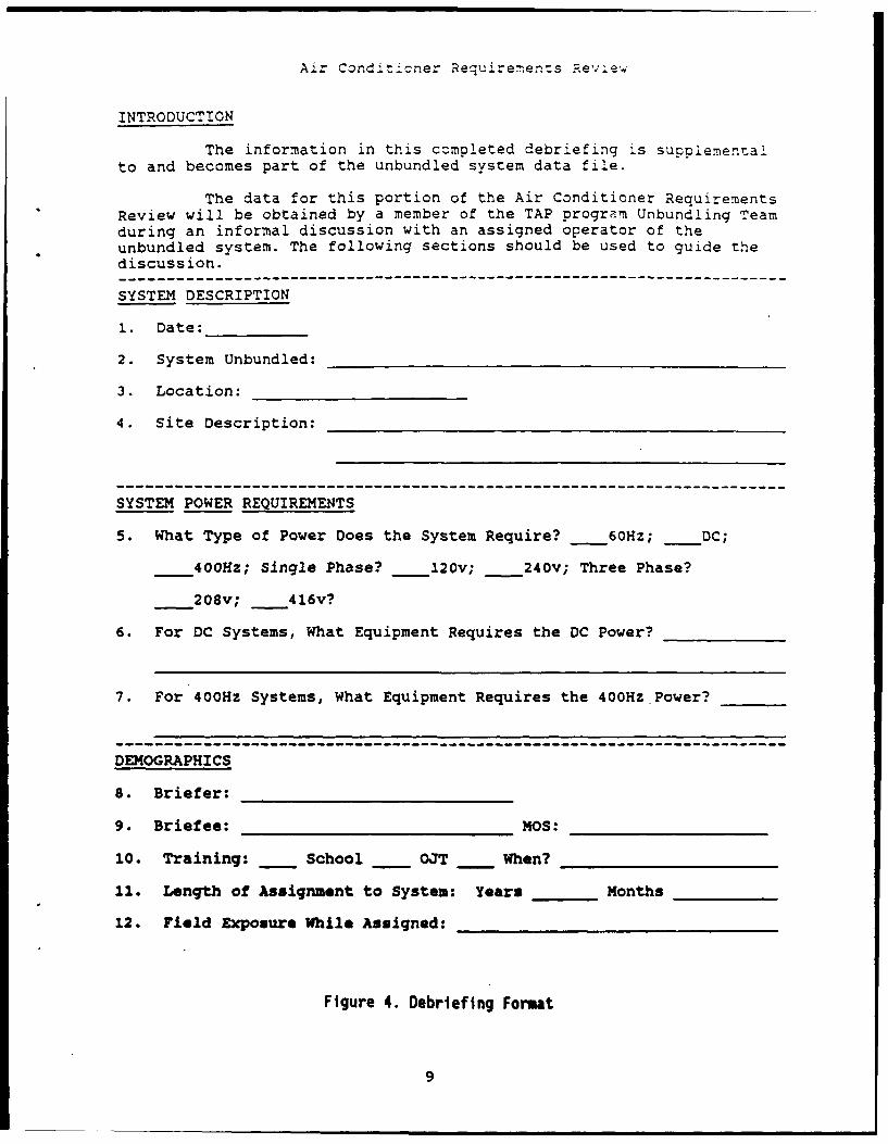
Notes about shelter size, trailer information, prime movers,generators, and air conditioners are taken. Operators andcrew members are debriefed to gain insight to operatingmodes, operating conditions, training, and fieldexperiences. Debriefings are based on the format presentedin Figure 4.
2
The collection team reviews the information gathered andconducts an initial analysis to insure values of voltage,current, and wattage are available for each component; eithermeasured directly or calculated from other measured values.
POWER ANALYSIS
Values recorded on the Power Generator Performance Data Formare verified by the Systems Assessment Team at Fort Belvoirusing procedures calculated to establish the power values to beused later in Fort Belvoir's Shelter Systems Assessment Model(SAM).
SAM is exercised to determine cooling requirements tomaintain Human Engineering habitability conditions(MIL-STD-1472) at various climate conditions.
TACFIRE DESCRIPTION
TACFIRE is an automated fire direction center used by fieldartillery organizations to plan, control, and direct friendlyartillery fires. The center contains ruggedized computer andcommunications components in an S-280 tactical shelter. Theshelter is carried on a 5-ton truck. The 5-ton truck tows a15KW, diesel generator for 400HZ electrical power. TACFIRE maybe located at DIVARTY and brigades, as well as artillerybattalions. Mission requests and target information is typicallyreceived by digital link from the fire support element, forwardobservers, fire support teams (FIST), mortar and locatingradars, and area air and ground surveillance systems.
TACFIRE POWER CONSUMING EQUIPMENT INVENTORY
The brigade TACFIRE assessed is identified as Fire DirectionCenter, Artillery, Line Item Number F55750, NSN7010-01-017-7040, OL-48B/GSG-10(V). It is assigned to 5thBattalion, 8th Field Artillery Brigade at Fort Bragg, NorthCarolina. The shelter is environmentally controlled by one,front-mounted, 18,000 BTU air conditioner, model F 18H-4. Theshelter is also equipped with a front-mounted, model M56decontamination unit. Internal components are furnished 208VACdirectly and 28 VOC indirectly via a power converter group. Thesubsystem components which make up the power consumers inTACFIRE are:
3
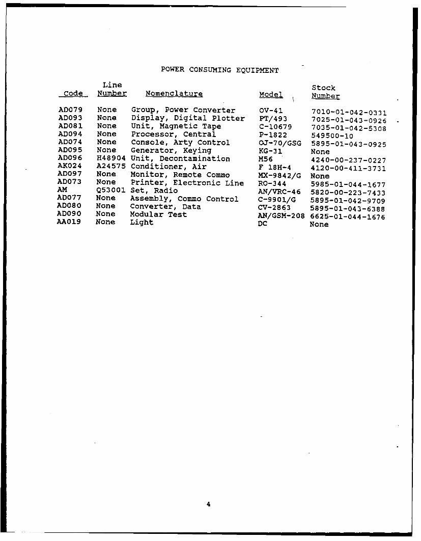
POWER CONSUMING EQUIPMENT
Line StockCode Number Nomenclature Model Number
AD079 None Group, Power Converter OV-41 7010-01-042-0331AD093 None Display, Digital Plotter PT/493 7025-01-043-0926AD081 None Unit, Magnetic Tape C-10679 7035-01-042-5308AD094 None Processor, Central P-1822 549500-10AD074 None Console, Arty Control OJ-70/GSG 5895-01-043-0925AD095 None Generator, Keying KG-31 NoneAD096 H48904 Unit, Decontamination M56 4240-00-237-0227AK024 A24575 Conditioner, Air F 18H-4 4120-00-411-3731AD097 None Monitor, Remote Commo MX-9842/G NoneAD073 None Printer, Electronic Line RO-344 5985-01-044-1677AM Q53001 Set, Radio AN/VRC-46 5820-00-223-7433AD077 None Assembly, Commo Control C-9901/G 5895-01-042-9709ADO80 None Converter, Data CV-2863 5895-01-043-6388ADO90 None Modular Test AN/GSM-208 6625-01-044-1676AA019 None Light DC None
4
DEBRIEFING
A debriefing plan had not been approved for use at the time of theTACFIRE assessment.
5
II I I- - - - - - - - - - - - - - i
Fa
Io
Si j
I o£ 1 '
! &p -
a
IE
K 0
6u 4
' ,
I" n ,
... . . . . L a..II
K Cao(UI 1-
di di ---.- - -
Oh - -40 £4~.
CL 0 Ca
(Ua
4,Cas
C - -- -- - --- Eo 01-=EU
asz(0.= 1.~ c - - ---- a'
0 3-o a('3Cl 0 - -- - - - - - -
(~j(I,.~0C ~a' I.-
=U..
(A -- - -
(Iia)2(0 E~.. ( 5 ~0j0) -
0)
ri.C, __ - - - .-------------
U,
Co00
7
a-d-
0-IV4-' II
II-cz
o
m >i
LL3C
U) .4---..-.- '
aC L. 10
c o
, %. C.
c 04
0 L0
Air Conditioner Requirements Review
INTRODUCTION
The information in this completed debriefing is supplemnentalto and becomes part of the unbundled system data file.
The data for this portion of the Air Conditioner RequirementsReview will be obtained by a member of the TAP program Unbundling Teamduring an informal discussion with an assigned operator of theunbundled system. The following sections should be used to guide thediscussion.
SYSTEM DESCRIPTION
1. Date: _____
2. System Unbundled: _______________________
3. Location:______ _____
4. Site Description: ______________________
SYSTEM POWER REQUIREMENTS
5. What Type of Power Does the System Require? 60Hz; _DC;
400Hz; Single Phase? _120v; _240v; Three Phase?
208v; 4160?
6. For DC Systems, What Equipment Requires the DC Power? ______
7. For 400Hz Systems, What Equipment Requires the 400Hz Power? ___
DEMOGRAPHICS
8. Briefer:_________ _____
9. Briefee: ________________10: _________
10. Training: - School _ OJT _ When?___________
11. Length of Assignment to System: Years _ ___Months _____
12. Field Exposure While Assigned:________________
Figure 4. Debriefing Format
9
Air Conditioner Requirements Review
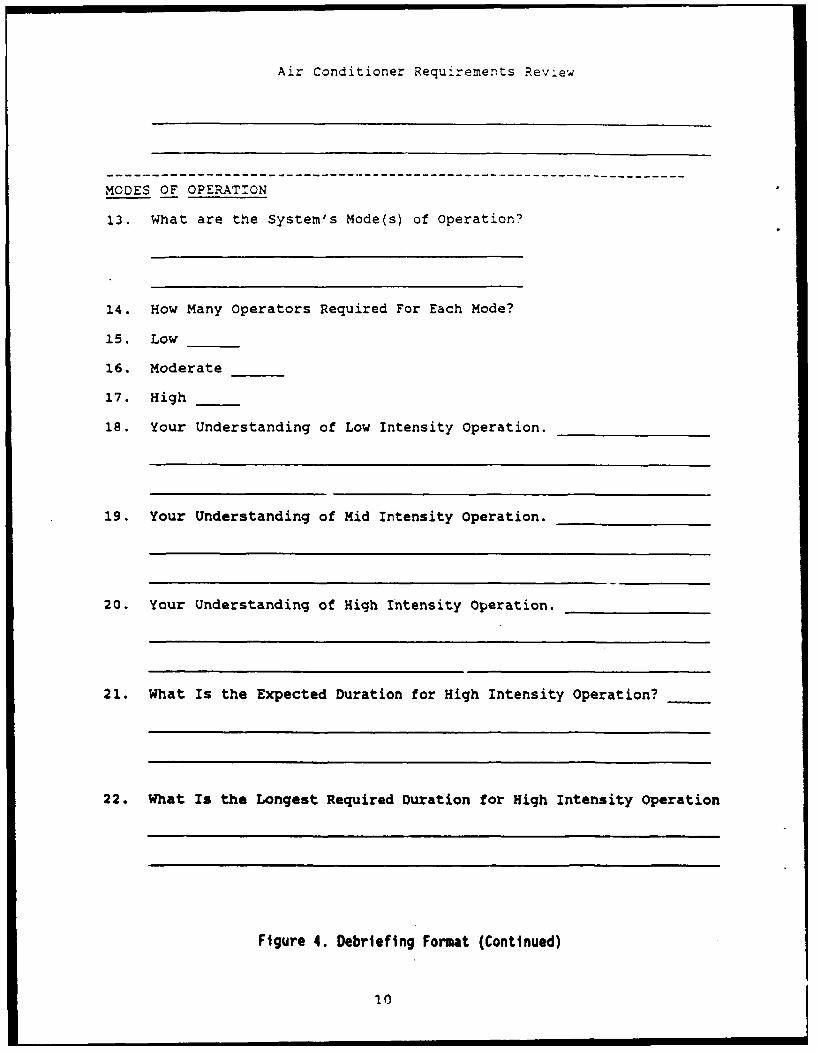
MODES OF OPERATION
13. What are the System's Mode(s) of Operation?
14. How Many Operators Required For Each Mode?
15. Low
16. Moderate
17. High _
18. Your Understanding of Low Intensity Operation.
19. Your Understanding of Mid Intensity Operation.
20. Your Understanding of High Intensity Operation.
21. What Is the Expected Duration for High Intensity Operation?
22. What Is the Longest Required Duration for High Intensity Operation
Figure 4. Debriefing Format (Continued)
10
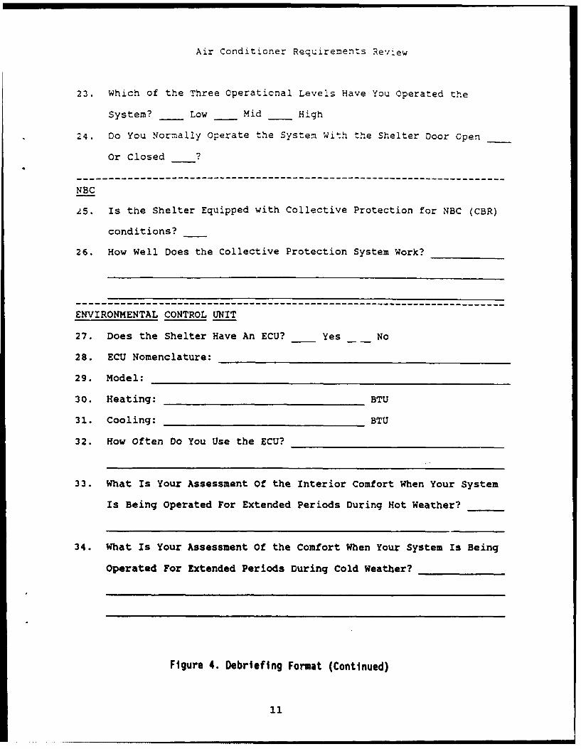
Air Conditioner Requirements Review
23. Which of the Three Operational Levels Have You Operated the
System? Low Mid High
24. Do You Normally Operate the System With the Shelter Door Open
Or Closed ?
NBC
25. Is the Shelter Equipped with Collective Protection for NBC (CBR)
conditions?
26. How Well Does the Collective Protection System Work?
-------------------------------------------------------
ENVIRONMENTAL CONTROL UNIT
27. Does the Shelter Have An ECU? Yes No
28. ECU Nomenclature:
29. Model:
30. Heating: BTU
31. Cooling: BTU
32. How Often Do You Use the ECU?
33. What Is Your Assessment Of the Interior Comfort When Your System
Is Being Operated For Extended Periods During Hot Weather?
34. What Is Your Assessment Of the Comfort When Your System Is Being
Operated For Extended Periods During Cold Weather?
Figure 4. Debriefing Format (Continued)
11
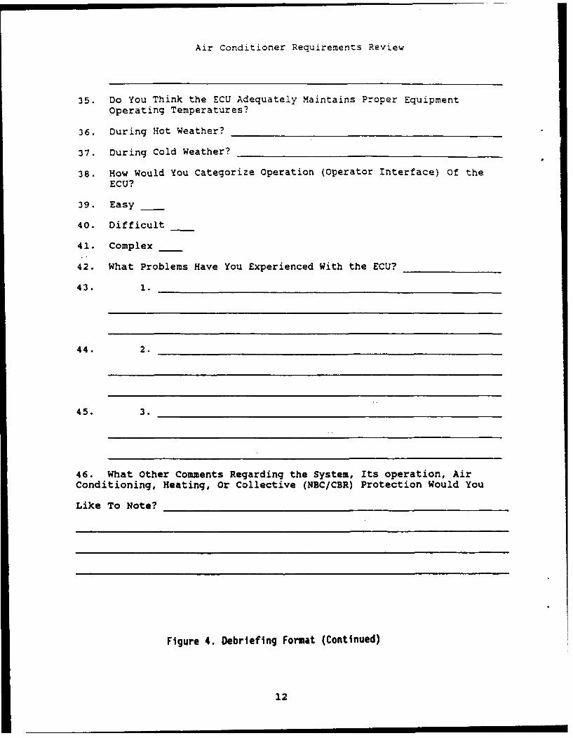
Air Conditioner Requirements Review
35. Do You Think the ECU Adequately Maintains Proper EquipmentOperating Temperatures?
36. During Hot Weather?___________ ___________
37. During Cold Weather? _____________________
38. How would You Categorize Operation (Operator Interface) Of theECU?
39. Easy
40. Difficult
41. Complex
42. What Problems Have You Experienced With the ECU?________
43. 1. __ _ _ _ _ _ _ _ _ _ _ _ _ _ _ _ _ _ _ _ _ _ _ _ _ _ _ _ _
44. 2.__________________________ __
45. 3.______________________________
46. What Other Comments Regarding the System, Its operation, AirConditioning, Heating, Or Collective (NEC/CER) Protection Would You
Like To Note?_______________________ ______
Figure 4. Debriefing Format (Continued)
12
Distribution for Report No. 2523
1 Director, Technical Information I HQ Air Force Civil Engineering Support Agency,Defense Advanced Research Projects Agency RAAE1400 Wilson Blvd. ATl1N: C. CalobrisiArlington, VA 22209 Tyndall AFB, FL 32403-6001
2 Defense Technical Information Center Product Manager, PEO, Air DefenseCameron Station 1 ATTN: SFAE-AD-GSLA1TN: DTIC-FDAC 1 ATTN: SFAE-AD-LUAlexandria, VA 22304-6145 1 ATTN: SFAE-AD-FM
I ATTN: SFAE-AD-PA1 DOD Project Manager 1 ATTN: SFAE-AD-AUG
Mobile Electric Power 1 ATIN: SFAE-CC-AD7500 Backlick Road Redstone Arsenal, AL 35898-5796Springfield VA 22150
1 Project Manager, PEO,I Commander Armored Systems Modernization
US Army Missile Research and AIN: SFAE-ASM-BVDevelopment Command ATTN: SFAE-ASM-CV
ATIN: AMSMI-PR ATIN: SFAE-ASM-SSRedstone Arsenal, AL 35809 Warren, MI 48397-5000
SDirector Project Manager, PEO,US Army Mateiel System Analysis Agency Command Control SystemsATTN: AMXSY-MP 1 ATTN. SFAE-CC-C-SAberdeen Proving Ground, MD 21010-5071 1 ATIN: SFAE-CC-FS
1 ATrN: SFAE-CC-MVR1 US Army Tank Automotive Command Fort Monmouth, N 07703-5000
ATTN: DRSTA-TSLWarren, NO 48090 Project Manager, PEO,
Inelligence and Electronic Warfare1 Commander I ATTN: SFAE-IEU-EU
US Army Electronics Research and 1 ATrN: SFAE-IEU-JSDevelopment Command I ATIN: SFAE-IEU-RD
ATIN: DELSD-L Fort Monmouth, NJ 07703-5000Fort Monmouth, NJ 07703-5301
Product Manager, PEO,SCommander Ieligence and Electrn Warfare
Rock Island Amenal I AflN: SFAE-IEU-SGATTN. SARRI-LPL Vimt Hill Fams StationRock Island, IL 61299-7300 Warrenton, VA 22186-5116
Project Mtager, PEO, 1 CommanderCommnumion Systems Ordnance Center and School
1 ATTN- SFAE-CM-ADD AT1N: ATSL-CDI ATTN. SFAE-CM-EP Abadn Proving Ground, MD 21005-52011 ATTN: SFAE-CM-MSE1 ATTN: SFAE-CM-MCS 1 HQDA, FARD-Tr1 ATIN: SFAE-CM-SC WahiDgton, DC 20310-0103
Fort ManKmoth, D 07703-5000
Dstrlbutlon-1
Belvoir RD&E Center
CirculateI Commander STRBE-Z
Technical Director STRBE-ZTAssoc Tech Dir (E&A) STRBE-ZTEAssoc Tech Dir (R&D) STRBE-ZRESergeant Major STRBE-ZMAdvanced Systems Concept Dir STRBE-H
4 STRBE-F3 STRBE-FE20 STRBE-FEA2 Tech Reports Ofc ASQNK-BVP-G3 Security Ofc (for liaison officers) STRBE-WS2 Technical Library STRBE-BT1 Public Affairs Ofc STRBE-IN1 Ofc of Chief Counsel STRBE-L
Distrlbutlon-2