Embed Size (px)
Citation preview
INSTRUCTION MANUAL
BEDIENUNGSANLEITUNG
MANUEL D’UTILISATION
MANUALE DI ISTRUZIONI1/8 ELECTRIC BUGGYECX04000
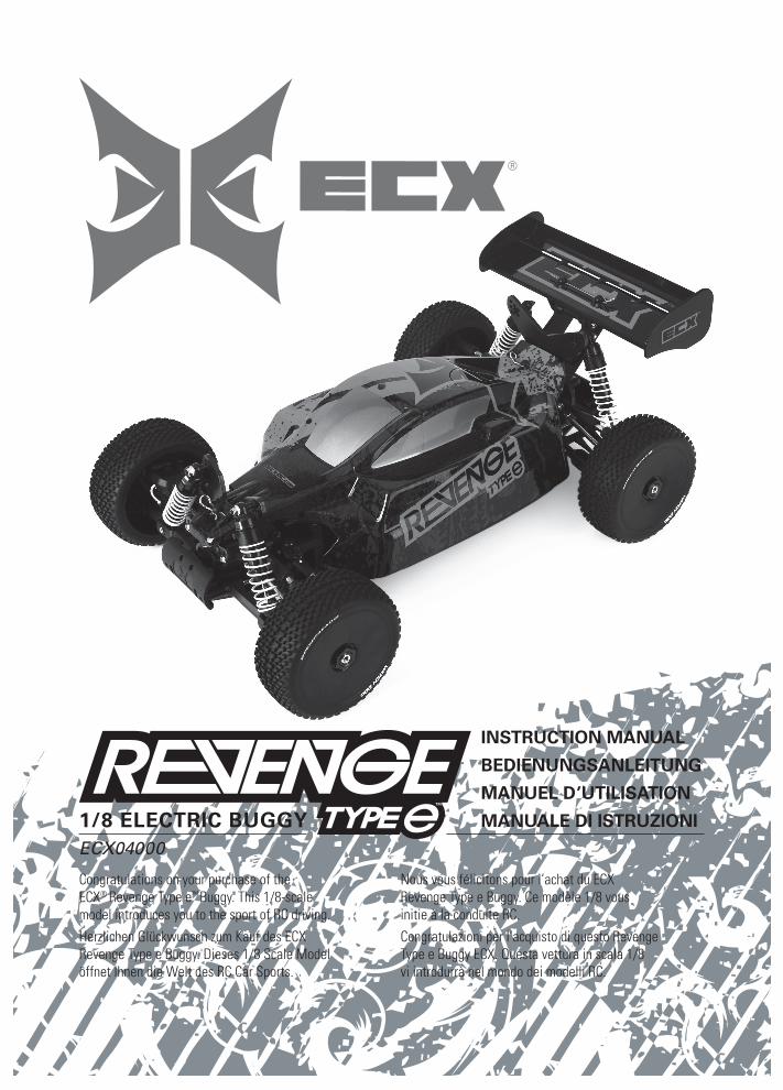
Congratulations on your purchase of the ECX® Revenge Type e™ Buggy. This 1/8-scale model introduces you to the sport of RC driving. Herzlichen Glückwunsch zum Kauf des ECX
Revenge Type e Buggy. Dieses 1/8 Scale Model öffnet Ihnen die Welt des RC Car Sports.
Nous vous félicitons pour l’achat du ECX
Revenge Type e Buggy. Ce modèle 1/8 vous initie à la conduite RC.Congratulazioni per l’acquisto di questo Revenge Type e Buggy ECX. Questa vettura in scala 1/8 vi introdurrà nel mondo dei modelli RC.
EN
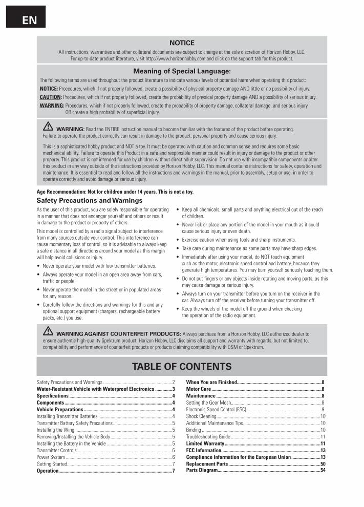
NOTICEAll instructions, warranties and other collateral documents are subject to change at the sole discretion of Horizon Hobby, LLC.
For up-to-date product literature, visit http://www.horizonhobby.com and click on the support tab for this product.
WARNING: Read the ENTIRE instruction manual to become familiar with the features of the product before operating. Failure to operate the product correctly can result in damage to the product, personal property and cause serious injury.
This is a sophisticated hobby product and NOT a toy. It must be operated with caution and common sense and requires some basic mechanical ability. Failure to operate this Product in a safe and responsible manner could result in injury or damage to the product or other property. This product is not intended for use by children without direct adult supervision. Do not use with incompatible components or alter this product in any way outside of the instructions provided by Horizon Hobby, LLC. This manual contains instructions for safety, operation and maintenance. It is essential to read and follow all the instructions and warnings in the manual, prior to assembly, setup or use, in order to operate correctly and avoid damage or serious injury.
Age Recommendation: Not for children under 14 years. This is not a toy.
Meaning of Special Language:The following terms are used throughout the product literature to indicate various levels of potential harm when operating this product:
NOTICE: Procedures, which if not properly followed, create a possibility of physical property damage AND little or no possibility of injury.
CAUTION: Procedures, which if not properly followed, create the probability of physical property damage AND a possibility of serious injury.
WARNING: Procedures, which if not properly followed, create the probability of property damage, collateral damage, and serious injury OR create a high probability of superficial injury.
TABLE OF CONTENTS
Safety Precautions and Warnings .........................................................2Water-Resistant Vehicle with Waterproof Electronics ..............3Specifications .....................................................................................4Components .........................................................................................4Vehicle Preparations .........................................................................4Installing Transmitter Batteries .............................................................4Transmitter Battery Safety Precautions .................................................5Installing the Wing.................................................................................5Removing/Installing the Vehicle Body ...................................................5Installing the Battery in the Vehicle ......................................................5Transmitter Controls ...............................................................................6Power System ........................................................................................6Getting Started.......................................................................................7Operation..............................................................................................7
When You are Finished ......................................................................8Motor Care ...........................................................................................8Maintenance .......................................................................................8Setting the Gear Mesh...........................................................................8Electronic Speed Control (ESC) ..............................................................9Shock Cleaning......................................................................................10Additional Maintenance Tips ................................................................10Binding ..................................................................................................10Troubleshooting Guide ..........................................................................11Limited Warranty ...............................................................................11FCC Information..................................................................................13Compliance Information for the European Union ........................13Replacement Parts ............................................................................50 Parts Diagram.....................................................................................54
WARNING AGAINST COUNTERFEIT PRODUCTS: Always purchase from a Horizon Hobby, LLC authorized dealer to ensure authentic high-quality Spektrum product. Horizon Hobby, LLC disclaims all support and warranty with regards, but not limited to, compatibility and performance of counterfeit products or products claiming compatibility with DSM or Spektrum.
Safety Precautions and WarningsAs the user of this product, you are solely responsible for operating in a manner that does not endanger yourself and others or result in damage to the product or property of others.
This model is controlled by a radio signal subject to interference from many sources outside your control. This interference can cause momentary loss of control, so it is advisable to always keep a safe distance in all directions around your model as this margin will help avoid collisions or injury.
• Neveroperateyourmodelwithlowtransmitterbatteries.
• Alwaysoperateyourmodelinanopenareaawayfromcars, traffic or people.
• Neveroperatethemodelinthestreetorinpopulatedareas for any reason.
• Carefullyfollowthedirectionsandwarningsforthisandanyoptional support equipment (chargers, rechargeable battery packs, etc.) you use.
• Keepallchemicals,smallpartsandanythingelectricaloutofthereach of children.
• Neverlickorplaceanyportionofthemodelinyourmouthasitcould cause serious injury or even death.
• Exercisecautionwhenusingtoolsandsharpinstruments.
• Takecareduringmaintenanceassomepartsmayhavesharpedges.
• Immediatelyafterusingyourmodel,doNOTtouchequipment such as the motor, electronic speed control and battery, because they generate high temperatures. You may burn yourself seriously touching them.
• Donotputfingersoranyobjectsinsiderotatingandmovingparts,asthismay cause damage or serious injury.
• Alwaysturnonyourtransmitterbeforeyouturnonthereceiverinthe car. Always turn off the receiver before turning your transmitter off.
• Keepthewheelsofthemodeloffthegroundwhenchecking the operation of the radio equipment.
EN
3
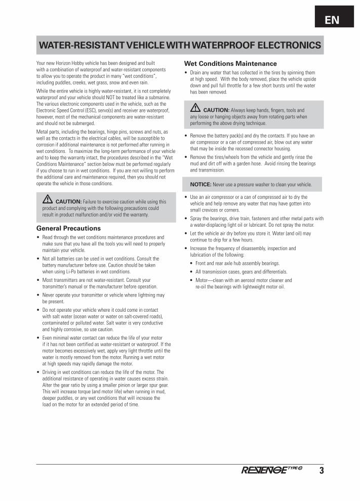
WATER-RESISTANT VEHICLE WITH WATERPROOF ELECTRONICS
Your new Horizon Hobby vehicle has been designed and built with a combination of waterproof and water-resistant components to allow you to operate the product in many “wet conditions”, including puddles, creeks, wet grass, snow and even rain.
While the entire vehicle is highly water-resistant, it is not completely waterproof and your vehicle should NOT be treated like a submarine. The various electronic components used in the vehicle, such as the Electronic Speed Control (ESC), servo(s) and receiver are waterproof, however, most of the mechanical components are water-resistant and should not be submerged.
Metal parts, including the bearings, hinge pins, screws and nuts, as well as the contacts in the electrical cables, will be susceptible to corrosion if additional maintenance is not performed after running in wetconditions.Tomaximizethelong-termperformanceofyourvehicleand to keep the warranty intact, the procedures described in the “Wet Conditions Maintenance” section below must be performed regularly if you choose to run in wet conditions. If you are not willing to perform the additional care and maintenance required, then you should not operate the vehicle in those conditions.
CAUTION:Failuretoexercisecautionwhileusingthisproduct and complying with the following precautions could result in product malfunction and/or void the warranty.
General Precautions• Readthroughthewetconditionsmaintenanceproceduresand
make sure that you have all the tools you will need to properly maintain your vehicle.
• Notallbatteriescanbeusedinwetconditions.Consultthe battery manufacturer before use. Caution should be taken when using Li-Po batteries in wet conditions.
• Mosttransmittersarenotwater-resistant.Consultyourtransmitter’s manual or the manufacturer before operation.
• Neveroperateyourtransmitterorvehiclewherelightningmay be present.
• Donotoperateyourvehiclewhereitcouldcomeincontactwith salt water (ocean water or water on salt-covered roads), contaminated or polluted water. Salt water is very conductive and highly corrosive, so use caution.
• Evenminimalwatercontactcanreducethelifeofyourmotor if it has not been certified as water-resistant or waterproof. If the motorbecomesexcessivelywet,applyverylightthrottleuntilthewater is mostly removed from the motor. Running a wet motor at high speeds may rapidly damage the motor.
• Drivinginwetconditionscanreducethelifeofthemotor.Theadditionalresistanceofoperatinginwatercausesexcessstrain.Alter the gear ratio by using a smaller pinion or larger spur gear. This will increase torque (and motor life) when running in mud, deeper puddles, or any wet conditions that will increase the loadonthemotorforanextendedperiodoftime.
Wet Conditions Maintenance• Drainanywaterthathascollectedinthetiresbyspinningthem
at high speed. With the body removed, place the vehicle upside down and pull full throttle for a few short bursts until the water has been removed.
CAUTION: Always keep hands, fingers, tools and any loose or hanging objects away from rotating parts when performing the above drying technique.
• Removethebatterypack(s)anddrythecontacts.Ifyouhavean air compressor or a can of compressed air, blow out any water that may be inside the recessed connector housing.
• Removethetires/wheelsfromthevehicleandgentlyrinsethe mud and dirt off with a garden hose. Avoid rinsing the bearings and transmission.
NOTICE: Never use a pressure washer to clean your vehicle.
• Useanaircompressororacanofcompressedairtodrythe vehicle and help remove any water that may have gotten into small crevices or corners.
• Spraythebearings,drivetrain,fastenersandothermetalpartswitha water-displacing light oil or lubricant. Do not spray the motor.
• Letthevehicleairdrybeforeyoustoreit.Water(andoil)maycontinue to drip for a few hours.
• Increasethefrequencyofdisassembly,inspectionand lubrication of the following:
• Frontandrearaxlehubassemblybearings.
• Alltransmissioncases,gearsanddifferentials.
• Motor—cleanwithanaerosolmotorcleanerand re-oil the bearings with lightweight motor oil.
EN
4
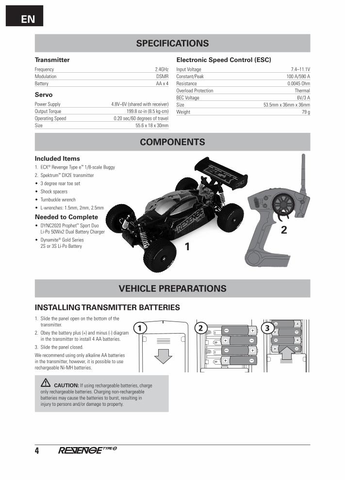
TransmitterFrequency 2.4GHzModulation DSMRBattery AAx4
ServoPower Supply 4.8V~6V (shared with receiver)Output Torque 199.8 oz-in (8.5 kg-cm)Operating Speed 0.20 sec/60 degrees of travelSize 55.6x18x30mm
Electronic Speed Control (ESC)Input Voltage 7.4–11.1VConstant/Peak 100 A/590 AResistance 0.0045 OhmOverload Protection ThermalBECVoltage 6V/3ASize 53.5mmx36mmx36mmWeight 79 g
1
Included Items1. ECX® Revenge Type e™ 1/8-scale Buggy
2. Spektrum™ DX2E transmitter
• 3degreereartoeset
• Shock spacers
• Turnbuckle wrench
• L-wrenches: 1.5mm, 2mm, 2.5mm
Needed to Complete• DYNC2020 Prophet™ Sport Duo
Li-Po50Wx2DualBatteryCharger
• Dynamite® Gold Series 2Sor3SLi-PoBattery
2
POWER
ST. TRIM
TH. TRIM
ST. RATE
VEHICLE PREPARATIONS
1. Slide the panel open on the bottom of the transmitter.
2. Obey the battery plus (+) and minus (-) diagram in the transmitter to install 4 AA batteries.
3. Slidethepanelclosed.
We recommend using only alkaline AA batteries in the transmitter, however, it is possible to use rechargeable Ni-MH batteries.
CAUTION: If using rechargeable batteries, charge only rechargeable batteries. Charging non-rechargeable batteries may cause the batteries to burst, resulting in injury to persons and/or damage to property.
INSTALLING TRANSMITTER BATTERIES
31 2
COMPONENTS
SPECIFICATIONS
EN
5
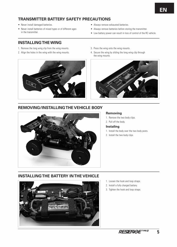
INSTALLING THE WING1. Remove the long wing clip from the wing mounts.
2. Align the holes in the wing with the wing mounts.
3. Pressthewingontothewingmounts.
4. Secure the wing by sliding the long wing clip through the wing mounts.
INSTALLING THE BATTERY IN THE VEHICLE
REMOVING/INSTALLING THE VEHICLE BODYRemoving1. Remove the two body clips.
2. Pull off the body.
Instaling1. Install the body over the two body posts.
2. Install the two body clips.
1. Loosen the hook and loop straps.
2. Install a fully charged battery.
3. Tightenthehookandloopstraps.
• Neverinstalldamagedbatteries.
• Neverinstallbatteriesofmixedtypesorofdifferentages in the transmitter.
• Alwaysremoveexhaustedbatteries.
• Alwaysremovebatteriesbeforestoringthetransmitter.
• LowbatterypowercanresultinlossofcontroloftheRCvehicle.
TRANSMITTER BATTERY SAFETY PRECAUTIONS
EN
6
TRANSMITTER CONTROLS
BIND THST
N R N R
POWER
ST. TRIM
TH. TRIM
ST. RATE
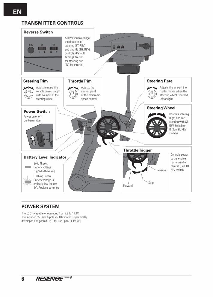
Reverse SwitchAllows you to change the direction of steering (ST. REV) and throttle (TH. REV) controls. (Default settings are “R” for steering and “N” for throttle)
BIND THST
N R N R
Adjusts the neutral point of the electronic speed control
Throttle Trim
Adjust to make the vehicle drive straight with no input at the steering wheel
Steering Trim
Battery Level Indicator
Solid Green: Battery voltage is good (Above 4V)
Flashing Green: Battery voltage is critically low (below 4V). Replace batteries
Power SwitchPower on or off the transmitter
POWER
ST. TRIM
TH. TRIM
ST. RATE
Steering Wheel
Controls steering. Right and Left steering with ST. REV Switch on R (See ST. REV switch)
Steering Rate
Adjusts the amount the rudder moves when the steering wheel is turned left or right
Throttle TriggerControls power to the engine for forward or reverse (See TH. REV switch)
POWER
ST. TRIM
TH. TRIM
ST. RATE
Stop
Reverse
Forward
POWER SYSTEMThe ESC is capable of operating from 7.2 to 11.1V. The included 550 size 4-pole 2500Kv motor is specifically developedandgeared(16T)foruseupto11.1V(3S).
EN
7
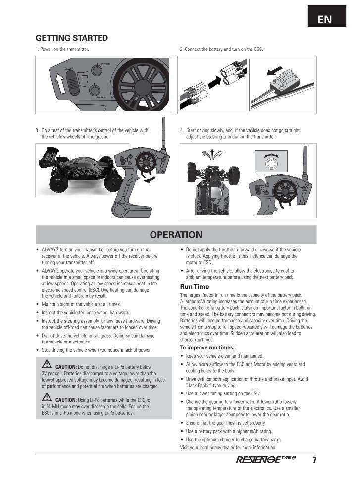
GETTING STARTED2. Connect the battery and turn on the ESC.
3. Doatestofthetransmitter’scontrolofthevehiclewith the vehicle’s wheels off the ground.
POWER
ST. TRIM
TH. TRIM
ST. RATE
1. Power on the transmitter.
• ALWAYSturnonyourtransmitterbeforeyouturnonthe receiver in the vehicle. Always power off the receiver before turning your transmitter off.
• ALWAYSoperateyourvehicleinawideopenarea.Operating the vehicle in a small space or indoors can cause overheating at low speeds. Operating at low speed increases heat in the electronic speed control (ESC). Overheating can damage the vehicle and failure may result.
• Maintainsightofthevehicleatalltimes.
• Inspectthevehicleforloosewheelhardware.
• Inspectthesteeringassemblyforanyloosehardware.Driving the vehicle off-road can cause fasteners to loosen over time.
• Donotdrivethevehicleintallgrass.Doingsocandamage the vehicle or electronics.
• Stopdrivingthevehiclewhenyounoticealackofpower.
CAUTION: Do not discharge a Li-Po battery below 3Vpercell.Batteriesdischargedtoavoltagelowerthanthe lowest approved voltage may become damaged, resulting in loss of performance and potential fire when batteries are charged.
CAUTION:UsingLi-PobatterieswhiletheESCis in Ni-MH mode may over discharge the cells. Ensure the ESC is in Li-Po mode when using Li-Po batteries.
• Donotapplythethrottleinforwardorreverseifthevehicle is stuck. Applying throttle in this instance can damage the motor or ESC.
• Afterdrivingthevehicle,allowtheelectronicstocoolto ambienttemperaturebeforeusingthenextbatterypack.
Run TimeThe largest factor in run time is the capacity of the battery pack. AlargermAhratingincreasestheamountofruntimeexperienced. The condition of a battery pack is also an important factor in both run time and speed. The battery connectors may become hot during driving. Batteries will lose performance and capacity over time. Driving the vehicle from a stop to full speed repeatedly will damage the batteries and electronics over time. Sudden acceleration will also lead to shorter run times.
To improve run times:
• Keepyourvehiclecleanandmaintained.
• AllowmoreairflowtotheESCandMotorbyaddingventsandcooling holes to the body.
• Drivewithsmoothapplicationofthrottleandbrakeinput.Avoid"Jack Rabbit" type driving.
• UsealowertimingsettingontheESC.
• Changethegearingtoalowerratio.Alowerratiolowers theoperatingtemperatureoftheelectronics.Useasmaller pinion gear or larger spur gear to lower the gear ratio.
• Ensurethatthegearmeshissetproperly.
• UseabatterypackwithahighermAhrating.
• Usetheoptimumchargertochargebatterypacks.
Visit your local hobby dealer for more information.
OPERATION
4. Start driving slowly, and, if the vehicle does not go straight, adjust the steering trim dial on the transmitter.

EN
8
WHEN YOU ARE FINISHED
•Prolongmotorlifebypreventingoverheatingconditions. Unduemotorwearresultsfromfrequentturns,stopsand starts, pushing objects, driving in deep sand and tall grass, and driving continuously up hill.
•Over-temperatureprotectionisinstalledontheESC to prevent circuit damage, but cannot protect the motor from driving against heavy resistance.
MOTOR CARE
1. Remove the body. 2. Power off the ESC and disconnect the battery.
4. Remove the battery from the vehicle and recharge the battery.3. Poweroffthetransmitter.
MAINTENANCE
SETTING THE GEAR MESHThe gear mesh has already been set at the factory. Setting the gear mesh is only necessary when changing motors or gears.
Proper gear mesh (how the gear teeth meet) is important to the performance of the vehicle. When the gear mesh is too loose, the spur and pinion gears could be damaged. If the mesh is too tight, speed could be limited and the motor and ESC will overheat. Set the gear mesh by following these simple steps:
1. Loosen the 2 motor screws.
2. Put a small piece of paper (A) between the pinion and spur gears.
3. Pushthegearstogetherwhiletighteningthemotorscrews.
4. Rotate the gears to remove the paper. The gearing should move a small amount.
POWER
ST. TRIM
TH. TRIM
ST. RATE
A
EN
9
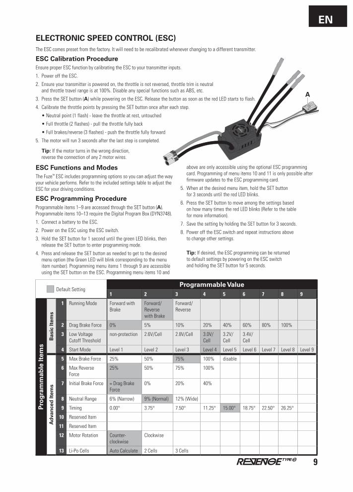
ELECTRONIC SPEED CONTROL (ESC)The ESC comes preset from the factory. It will need to be recalibrated whenever changing to a different transmitter.
ESC Calibration ProcedureEnsure proper ESC function by calibrating the ESC to your transmitter inputs.
1. Power off the ESC.
2. Ensure your transmitter is powered on, the throttle is not reversed, throttle trim is neutral and throttle travel range is at 100%. Disable any special functions such as ABS, etc.
3. PresstheSETbutton(A) while powering on the ESC. Release the button as soon as the red LED starts to flash.
4. Calibrate the throttle points by pressing the SET button once after each step.
•Neutralpoint(1flash)-leavethethrottleatrest,untouched
•Fullthrottle(2flashes)-pullthethrottlefullyback
•Fullbrakes/reverse(3flashes)-pushthethrottlefullyforward
5. Themotorwillrun3secondsafterthelaststepiscompleted.
Tip: If the motor turns in the wrong direction, reverse the connection of any 2 motor wires.
ESC Functions and ModesThe Fuze™ ESC includes programming options so you can adjust the way your vehicle performs. Refer to the included settings table to adjust the ESC for your driving conditions.
ESC Programming ProcedureProgrammable items 1–9 are accessed through the SET button (A). Programmableitems10–13requiretheDigitalProgramBox(DYN3748).
1. Connect a battery to the ESC.
2. Power on the ESC using the ESC switch.
3. HoldtheSETbuttonfor1seconduntilthegreenLEDblinks,thenrelease the SET button to enter programming mode.
4. Press and release the SET button as needed to get to the desired menu option (the Green LED will blink corresponding to the menu item number). Programming menu items 1 through 9 are accessible using the SET button on the ESC. Programming menu items 10 and
above are only accessible using the optional ESC programming card. Programming of menu items 10 and 11 is only possible after firmware updates to the ESC programming card.
5. When at the desired menu item, hold the SET button for3secondsuntiltheredLEDblinks.
6. Press the SET button to move among the settings based on how many times the red LED blinks (Refer to the table for more information).
7. SavethesettingbyholdingtheSETbuttonfor3seconds.
8. Power off the ESC switch and repeat instructions above to change other settings.
Tip: If desired, the ESC programming can be returned to default settings by powering on the ESC switch and holding the SET button for 5 seconds.
Default SettingProgrammable Value
1 2 3 4 5 6 7 8 9
Pro
gra
mm
able
Item
s
Bas
ic It
ems
1 Running Mode Forward with Brake
Forward/Reverse with Brake
Forward/Reverse
2 Drag Brake Force 0% 5% 10% 20% 40% 60% 80% 100%
3 Low Voltage Cutoff Threshold
non-protection 2.6V/Cell 2.8V/Cell 3.0V/Cell
3.2V/Cell
3.4V/Cell
4 Start Mode Level 1 Level 2 Level3 Level 4 Level 5 Level 6 Level 7 Level 8 Level 9
Ad
van
ced
Item
s
5 MaxBrakeForce 25% 50% 75% 100% disable
6 MaxReverseForce
25% 50% 75% 100%
7 Initial Brake Force = Drag Brake Force
0% 20% 40%
8 Neutral Range 6% (Narrow) 9% (Normal) 12% (Wide)
9 Timing 0.00° 3.75° 7.50° 11.25° 15.00° 18.75° 22.50° 26.25°
10 Reserved Item
11 Reserved Item
12 Motor Rotation Counter- clockwise
Clockwise
13 Li-Po Cells Auto Calculate 2 Cells 3Cells
A
EN
10
ADDITIONAL MAINTENANCE TIPS• Examineyourvehicleonaregularbasis.
• Useabrushtoremovedirtanddust.
• Lookfordamagetothesuspensionarmsaround other molded parts.
• Re-gluethetirestothewheels,ifnecessary.
• Usesuitabletoolstocheckandtightenfasteners.
• Makesurethecamberandsteeringlinkagesarenotbent. Replace any bent linkages.
• AdjusttheToeandCambersettings,ifnecessary.
• Removetheshocksandinspectthemfordamage. Rebuild the shocks on a regular basis or if oil is leaking.
• Inspecttheelectronicsandbatteriesforexposedwires. Repairexposedwireswithshrink-wrap,orreplacethewire.
• MakesuretheESCissecureonthechassis. Replace the double-sided tape, if necessary.
• Poweronthetransmitter.IfthegreenLEDisflashing, replace the AA batteries in your transmitter.
• Checkthepinionandspurgearforwear.
CleaningPerformance can be hindered if dirt gets in any of the moving suspensionparts.Usecompressedair,asoftpaintbrush,ora toothbrush to remove dust or dirt. Avoid using solvents or chemicals as they can actually wash dirt into the bearings or moving parts, as well as cause damage to the electronics.
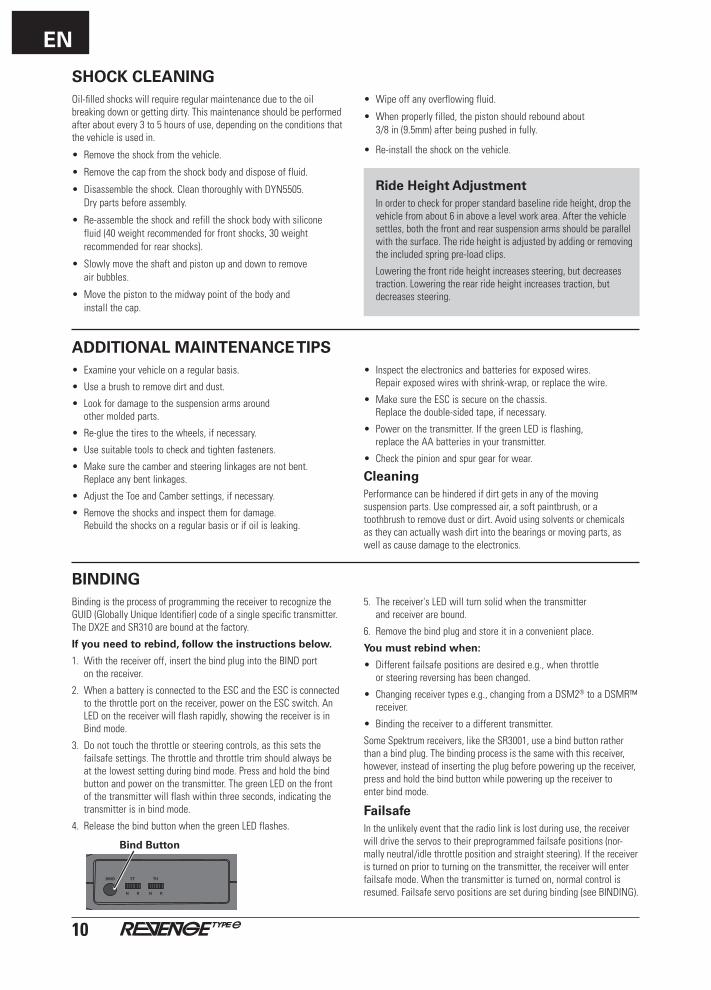
BINDING Binding is the process of programming the receiver to recognize the GUID(GloballyUniqueIdentifier)codeofasinglespecifictransmitter. TheDX2EandSR310areboundatthefactory.
If you need to rebind, follow the instructions below.
1. With the receiver off, insert the bind plug into the BIND port on the receiver.
2. When a battery is connected to the ESC and the ESC is connected to the throttle port on the receiver, power on the ESC switch. An LED on the receiver will flash rapidly, showing the receiver is in Bind mode.
3. Donottouchthethrottleorsteeringcontrols,asthissetsthefailsafe settings. The throttle and throttle trim should always be at the lowest setting during bind mode. Press and hold the bind button and power on the transmitter. The green LED on the front of the transmitter will flash within three seconds, indicating the transmitter is in bind mode.
4. Release the bind button when the green LED flashes.
BIND THST
N R N R
Bind Button
5. The receiver's LED will turn solid when the transmitter and receiver are bound.
6. Remove the bind plug and store it in a convenient place.
You must rebind when:
• Differentfailsafepositionsaredesirede.g.,whenthrottle or steering reversing has been changed.
• Changingreceivertypese.g.,changingfromaDSM2® to a DSMR™ receiver.
• Bindingthereceivertoadifferenttransmitter.
SomeSpektrumreceivers,liketheSR3001,useabindbuttonratherthan a bind plug. The binding process is the same with this receiver, however, instead of inserting the plug before powering up the receiver, press and hold the bind button while powering up the receiver to enter bind mode.
FailsafeIn the unlikely event that the radio link is lost during use, the receiver will drive the servos to their preprogrammed failsafe positions (nor-mally neutral/idle throttle position and straight steering). If the receiver is turned on prior to turning on the transmitter, the receiver will enter failsafe mode. When the transmitter is turned on, normal control is resumed. Failsafe servo positions are set during binding (see BINDING).
SHOCK CLEANINGOil-filled shocks will require regular maintenance due to the oil breaking down or getting dirty. This maintenance should be performed afteraboutevery3to5hoursofuse,dependingontheconditionsthat the vehicle is used in.
•Removetheshockfromthevehicle.
•Removethecapfromtheshockbodyanddisposeoffluid.
•Disassembletheshock.CleanthoroughlywithDYN5505. Dry parts before assembly.
•Re-assembletheshockandrefilltheshockbodywithsilicone fluid(40weightrecommendedforfrontshocks,30weightrecommended for rear shocks).
•Slowlymovetheshaftandpistonupanddowntoremove air bubbles.
•Movethepistontothemidwaypointofthebodyand install the cap.
•Wipeoffanyoverflowingfluid.
•Whenproperlyfilled,thepistonshouldreboundabout 3/8in(9.5mm)afterbeingpushedinfully.
• Re-installtheshockonthevehicle.
Ride Height AdjustmentIn order to check for proper standard baseline ride height, drop the vehicle from about 6 in above a level work area. After the vehicle settles, both the front and rear suspension arms should be parallel with the surface. The ride height is adjusted by adding or removing the included spring pre-load clips.
Lowering the front ride height increases steering, but decreases traction. Lowering the rear ride height increases traction, but decreases steering.
EN
11
LIMITED WARRANTY
What this Warranty CoversHorizon Hobby, LLC (Horizon) warrants to the original purchaser that the product purchased (the "Product") will be free from defects in materials and workmanship at the date of purchase.
What is Not CoveredThis warranty is not transferable and does not cover (i) cosmetic damage, (ii) damage due to acts of God, accident, misuse, abuse, negligence, commercial use, or due to improper use, installation, operation or maintenance, (iii) modification of or to any part of the Product, (iv) attempted service by anyone other than a Horizon Hobby authorized service center, (v) Product not purchased from an authorized Horizon dealer, or (vi) Product not compliant with applicable technical regulations.
OTHER THAN THE EXPRESS WARRANTY ABOVE, HORIZON MAKES NO OTHER WARRANTY OR REPRESENTATION, AND HEREBY DISCLAIMS ANYANDALLIMPLIEDWARRANTIES,INCLUDING,WITHOUTLIMITATION, THE IMPLIED WARRANTIES OF NON-INFRINGEMENT,
MERCHANTABILITYANDFITNESSFORAPARTICULARPURPOSE.THEPURCHASERACKNOWLEDGESTHATTHEYALONEHAVEDETERMINEDTHATTHEPRODUCTWILLSUITABLYMEETTHEREQUIREMENTSOFTHEPURCHASER’SINTENDEDUSE.
Purchaser’s RemedyHorizon’ssoleobligationandpurchaser’ssoleandexclusiveremedyshall be that Horizon will, at its option, either (i) service, or (ii) replace, any Product determined by Horizon to be defective. Horizon reserves the right to inspect any and all Product(s) involved in a warranty claim. Service or replacement decisions are at the sole discretion of Horizon. Proof of purchase is required for all warranty claims. SERVICE OR REPLACEMENTASPROVIDEDUNDERTHISWARRANTYISTHE PURCHASER’SSOLEANDEXCLUSIVEREMEDY.
Limitation of LiabilityHORIZON SHALL NOT BE LIABLE FOR SPECIAL, INDIRECT, INCIDENTAL ORCONSEQUENTIALDAMAGES,LOSSOFPROFITSORPRODUCTIONOR COMMERCIAL LOSS IN ANY WAY, REGARDLESS OF WHETHER
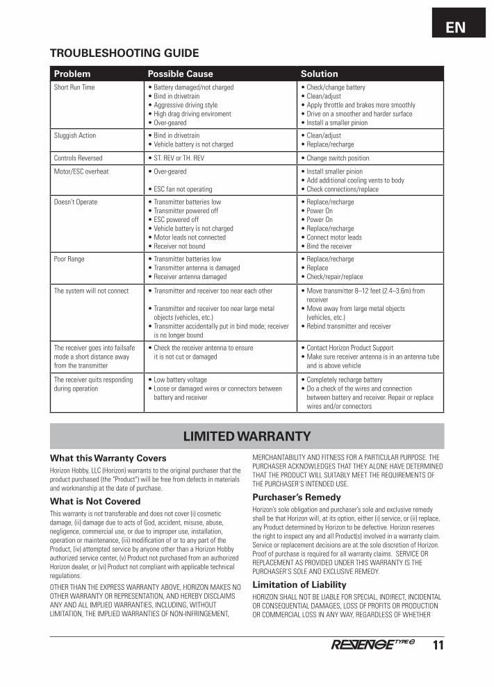
TROUBLESHOOTING GUIDE
Problem Possible Cause SolutionShort Run Time •Batterydamaged/notcharged
•Bindindrivetrain•Aggressivedrivingstyle•Highdragdrivingenviroment•Over-geared
•Check/changebattery •Clean/adjust•Applythrottleandbrakesmoresmoothly•Driveonasmootherandhardersurface•Installasmallerpinion
Sluggish Action •Bindindrivetrain •Vehiclebatteryisnotcharged
•Clean/adjust •Replace/recharge
Controls Reversed •ST.REVorTH.REV •Changeswitchposition
Motor/ESC overheat •Over-geared
•ESCfannotoperating
•Installsmallerpinion•Addadditionalcoolingventstobody•Checkconnections/replace
Doesn’t Operate •Transmitterbatterieslow •Transmitterpoweredoff •ESCpoweredoff •Vehiclebatteryisnotcharged•Motorleadsnotconnected•Receivernotbound
•Replace/recharge •PowerOn •PowerOn •Replace/recharge•Connectmotorleads•Bindthereceiver
Poor Range •Transmitterbatterieslow •Transmitterantennaisdamaged •Receiverantennadamaged
•Replace/recharge •Replace •Check/repair/replace
The system will not connect •Transmitterandreceivertooneareachother •Transmitterandreceivertoonearlargemetal
objects (vehicles, etc.)•Transmitteraccidentallyputinbindmode;receiver
is no longer bound
•Movetransmitter8–12feet(2.4–3.6m)fromreceiver
•Moveawayfromlargemetalobjects (vehicles, etc.)
•Rebindtransmitterandreceiver
The receiver goes into failsafe mode a short distance away from the transmitter
•Checkthereceiverantennatoensure it is not cut or damaged
•ContactHorizonProductSupport •Makesurereceiverantennaisinanantennatube
and is above vehicle
The receiver quits responding during operation
•Lowbatteryvoltage •Looseordamagedwiresorconnectorsbetween
battery and receiver
•Completelyrechargebattery •Doacheckofthewiresandconnection
between battery and receiver. Repair or replace wires and/or connectors
EN
12
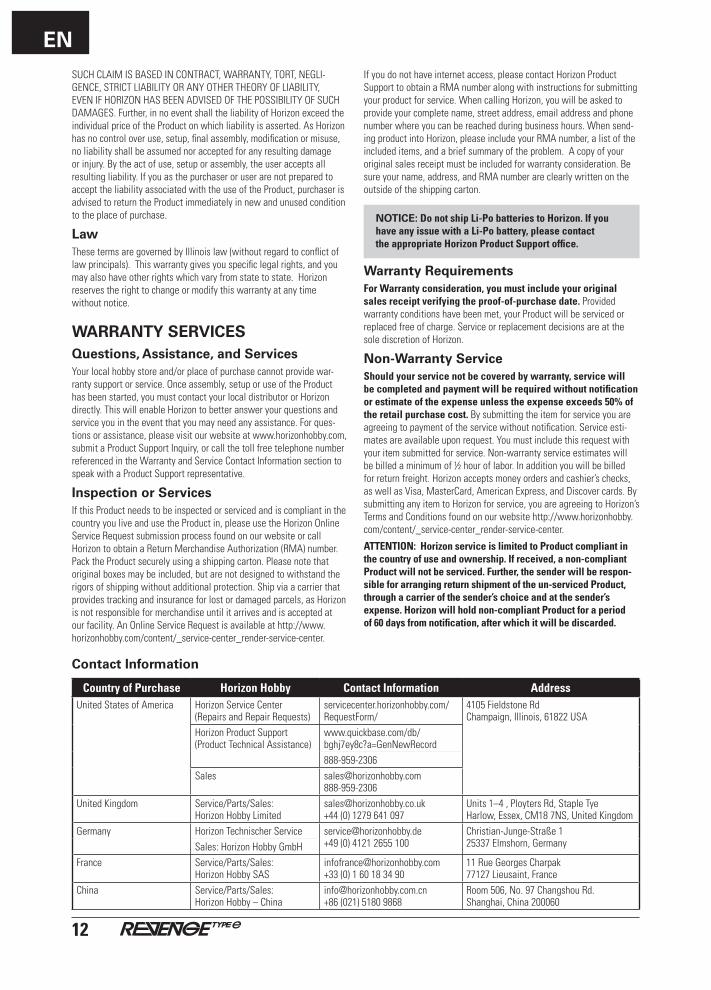
Contact Information
Country of Purchase Horizon Hobby Contact Information AddressUnitedStatesofAmerica Horizon Service Center
(Repairs and Repair Requests)servicecenter.horizonhobby.com/ RequestForm/
4105 Fieldstone Rd Champaign,Illinois,61822USA
Horizon Product Support(Product Technical Assistance)
www.quickbase.com/db/bghj7ey8c?a=GenNewRecord888-959-2306
Sales [email protected]
UnitedKingdom Service/Parts/Sales:Horizon Hobby Limited
[email protected]+44 (0) 1279 641 097
Units1–4,PloytersRd,StapleTyeHarlow,Essex,CM187NS,UnitedKingdom
Germany Horizon Technischer Service [email protected] +49 (0) 4121 2655 100
Christian-Junge-Straße 1 25337Elmshorn,GermanySales: Horizon Hobby GmbH
France Service/Parts/Sales: Horizon Hobby SAS
[email protected]+33(0)160183490
11 Rue Georges Charpak77127 Lieusaint, France
China Service/Parts/Sales: Horizon Hobby – China
[email protected]+86 (021) 5180 9868
Room 506, No. 97 Changshou Rd.Shanghai, China 200060
SUCHCLAIMISBASEDINCONTRACT,WARRANTY,TORT,NEGLI-GENCE, STRICT LIABILITY OR ANY OTHER THEORY OF LIABILITY, EVENIFHORIZONHASBEENADVISEDOFTHEPOSSIBILITYOFSUCHDAMAGES.Further,innoeventshalltheliabilityofHorizonexceedtheindividual price of the Product on which liability is asserted. As Horizon has no control over use, setup, final assembly, modification or misuse, no liability shall be assumed nor accepted for any resulting damage or injury. By the act of use, setup or assembly, the user accepts all resulting liability. If you as the purchaser or user are not prepared to accept the liability associated with the use of the Product, purchaser is advised to return the Product immediately in new and unused condition to the place of purchase.
LawThese terms are governed by Illinois law (without regard to conflict of law principals). This warranty gives you specific legal rights, and you may also have other rights which vary from state to state. Horizon reserves the right to change or modify this warranty at any time without notice.
WARRANTY SERVICESQuestions, Assistance, and ServicesYour local hobby store and/or place of purchase cannot provide war-ranty support or service. Once assembly, setup or use of the Product has been started, you must contact your local distributor or Horizon directly. This will enable Horizon to better answer your questions and service you in the event that you may need any assistance. For ques-tions or assistance, please visit our website at www.horizonhobby.com, submit a Product Support Inquiry, or call the toll free telephone number referenced in the Warranty and Service Contact Information section to speak with a Product Support representative.
Inspection or ServicesIf this Product needs to be inspected or serviced and is compliant in the country you live and use the Product in, please use the Horizon Online Service Request submission process found on our website or call Horizon to obtain a Return Merchandise Authorization (RMA) number. Pack the Product securely using a shipping carton. Please note that originalboxesmaybeincluded,butarenotdesignedtowithstandtherigors of shipping without additional protection. Ship via a carrier that provides tracking and insurance for lost or damaged parcels, as Horizon is not responsible for merchandise until it arrives and is accepted at our facility. An Online Service Request is available at http://www.horizonhobby.com/content/_service-center_render-service-center.
If you do not have internet access, please contact Horizon Product Support to obtain a RMA number along with instructions for submitting your product for service. When calling Horizon, you will be asked to provide your complete name, street address, email address and phone number where you can be reached during business hours. When send-ing product into Horizon, please include your RMA number, a list of the included items, and a brief summary of the problem. A copy of your original sales receipt must be included for warranty consideration. Be sure your name, address, and RMA number are clearly written on the outside of the shipping carton.
NOTICE: Do not ship Li-Po batteries to Horizon. If you have any issue with a Li-Po battery, please contact the appropriate Horizon Product Support office.
Warranty RequirementsFor Warranty consideration, you must include your original sales receipt verifying the proof-of-purchase date. Provided warranty conditions have been met, your Product will be serviced or replaced free of charge. Service or replacement decisions are at the sole discretion of Horizon.
Non-Warranty ServiceShould your service not be covered by warranty, service will be completed and payment will be required without notification or estimate of the expense unless the expense exceeds 50% of the retail purchase cost. By submitting the item for service you are agreeing to payment of the service without notification. Service esti-mates are available upon request. You must include this request with your item submitted for service. Non-warranty service estimates will be billed a minimum of ½ hour of labor. In addition you will be billed for return freight. Horizon accepts money orders and cashier’s checks, aswellasVisa,MasterCard,AmericanExpress,andDiscovercards.Bysubmitting any item to Horizon for service, you are agreeing to Horizon’s Terms and Conditions found on our website http://www.horizonhobby.com/content/_service-center_render-service-center.
ATTENTION: Horizon service is limited to Product compliant in the country of use and ownership. If received, a non-compliant Product will not be serviced. Further, the sender will be respon-sible for arranging return shipment of the un-serviced Product, through a carrier of the sender’s choice and at the sender’s expense. Horizon will hold non-compliant Product for a period of 60 days from notification, after which it will be discarded.
EN
13
COMPLIANCE INFORMATION FOR THE EUROPEAN UNION
This device complies with part 15 of the FCC rules. Operation is subject to the following two conditions: (1) This device may not cause harmful interference, and (2) this device must accept any interference received, including interference that may cause undesired operation.
CAUTION:Changesormodificationsnotexpressly approved by the party responsible for compliance could void the user’s authority to operate the equipment.
This product contains a radio transmitter with wireless technology which has been tested and found to be compliant with the applicable regulationsgoverningaradiotransmitterinthe2.400GHzto2.4835GHzfrequency range.
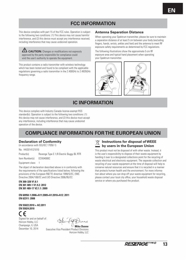
Antenna Separation DistanceWhen operating your Spektrum transmitter, please be sure to maintain aseparationdistanceofatleast5cmbetweenyourbody(excludingfingers, hands, wrists, ankles and feet) and the antenna to meet RF exposuresafetyrequirementsasdeterminedbyFCCregulations.
Thefollowingillustrationsshowtheapproximate5cmRF exposureareaandtypicalhandplacementwhenoperating your Spektrum transmitter.
FCC INFORMATION
Declaration of Conformity(in accordance with ISO/IEC 17050-1)
No. HH2014121010
Product(s): Revenge Type E 1/8 Electric Buggy BL RTR
Item Number(s): ECX04000C
Equipment class: 1
The object of declaration described above is in conformity with the requirements of the specifications listed below, following the provisions of the European R&TTE directive 1999/5/EC, EMC Directive 2004/108/EC and LVD Directive 2006/95/EC:
EN 300-328 V1.8.1 EN 301 489-1 V1.9.2: 2012 EN 301 489-17 V2.1.1: 2009 EN 60950-1:2006+A11:2009+A1:2010+A12: 2011 EN 62311: 2008 EN 55022:2010 + AC:2011 EN 55024:2010
Signed for and on behalf of: Horizon Hobby, LLC Champaign,ILUSA December 10, 2014
ThisdevicecomplieswithIndustryCanadalicense-exemptRSSstandard(s). Operation is subject to the following two conditions: (1) this device may not cause interference, and (2) this device must accept any interference, including interference that may cause undesired operation of the device.
IC INFORMATION
Instructions for disposal of WEEE by users in the European Union
This product must not be disposed of with other waste. Instead, it is the user’s responsibility to dispose of their waste equipment by handing it over to a designated collections point for the recycling of waste electrical and electronic equipment. The separate collection and recycling of your waste equipment at the time of disposal will help to conserve natural resources and ensure that it is recycled in a manner that protects human health and the environment. For more informa-tion about where you can drop off your waste equipment for recycling, please contact your local city office, your household waste disposal service or where you purchased the product.
Mike Dunne ExecutiveVicePresidentProductDivisions
Horizon Hobby, LLC