Embed Size (px)
Citation preview
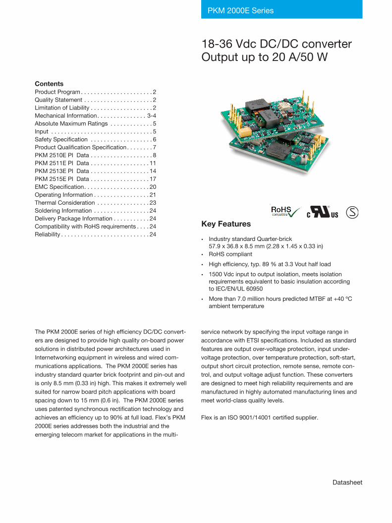
18-36 Vdc DC/DC converterOutput up to 20 A/50 W
PKM 2000E Series
ContentsProduct Program . . . . . . . . . . . . . . . . . . . . . . 2Quality Statement . . . . . . . . . . . . . . . . . . . . . 2Limitation of Liability . . . . . . . . . . . . . . . . . . . 2Mechanical Information . . . . . . . . . . . . . . . 3-4Absolute Maximum Ratings . . . . . . . . . . . . . 5Input . . . . . . . . . . . . . . . . . . . . . . . . . . . . . . . 5Safety Specification . . . . . . . . . . . . . . . . . . . 6Product Qualification Specification . . . . . . . . 7PKM 2510E PI Data . . . . . . . . . . . . . . . . . . . 8PKM 2511E PI Data . . . . . . . . . . . . . . . . . . 11PKM 2513E PI Data . . . . . . . . . . . . . . . . . . 14PKM 2515E PI Data . . . . . . . . . . . . . . . . . . 17
. . . 20 . . . 21 . . . 23 . . . 24 . . . 24 . . . 24 . . . 24
EMC Specification . . . . . . . . . . . . . . . . .Operating Information . . . . . . . . . . . . . .Thermal Consideration . . . . . . . . . . . . .Soldering Information . . . . . . . . . . . . . .Delivery Package Information . . . . . . . . Compatibility with RoHS requirements . Reliability . . . . . . . . . . . . . . . . . . . . . . . .
Datasheet
The PKM 2000E series of high efficiency DC/DC convert-ers are designed to provide high quality on-board power solutions in distributed power architectures used in Internetworking equipment in wireless and wired com-munications applications . The PKM 2000E series has industry standard quarter brick footprint and pin-out and is only 8 .5 mm (0 .33 in) high . This makes it extremely well suited for narrow board pitch applications with board spacing down to 15 mm (0 .6 in) . The PKM 2000E series uses patented synchronous rectification technology and achieves an efficiency up to 90% at full load . Flex’s PKM 2000E series addresses both the industrial and the emerging telecom market for applications in the multi-
service network by specifying the input voltage range in accordance with ETSI specifications . Included as standard features are output over-voltage protection, input under-voltage protection, over temperature protection, soft-start, output short circuit protection, remote sense, remote con-trol, and output voltage adjust function . These converters are designed to meet high reliability requirements and are manufactured in highly automated manufacturing lines and meet world-class quality levels .
Flex is an ISO 9001/14001 certified supplier .
Key Features
• Industry standard Quarter-brick57 .9 x 36 .8 x 8 .5 mm (2 .28 x 1 .45 x 0 .33 in)
• RoHS compliant
• High efficiency, typ . 89 % at 3 .3 Vout half load
• 1500 Vdc input to output isolation, meets isolationrequirements equivalent to basic insulation accordingto IEC/EN/UL 60950
• More than 7 .0 million hours predicted MTBF at +40 ºCambient temperature
EN/LZT 146 050 R4B ©Flex 2017PKM 2000E PI Datasheet
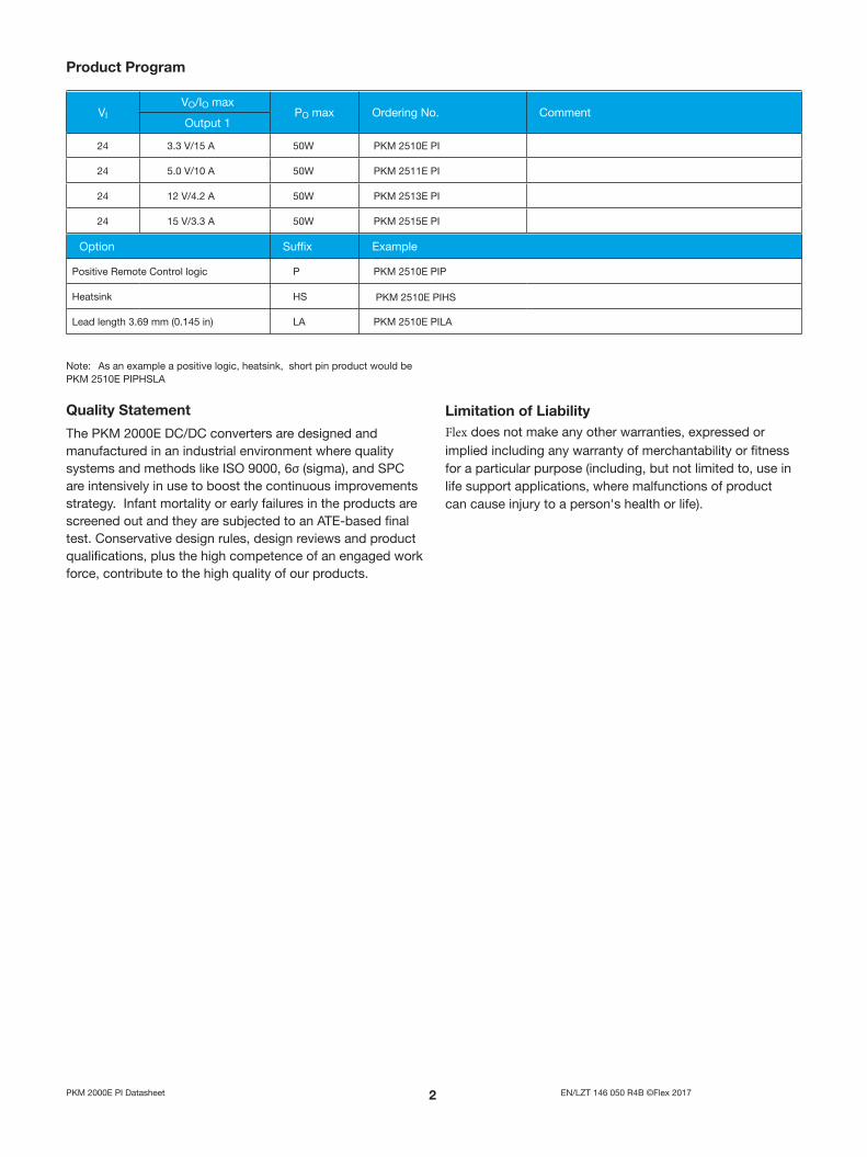
Product Program
Quality Statement
The PKM 2000E DC/DC converters are designed and manufactured in an industrial environment where quality systems and methods like ISO 9000, 6σ (sigma), and SPC are intensively in use to boost the continuous improvements strategy . Infant mortality or early failures in the products are screened out and they are subjected to an ATE-based final test . Conservative design rules, design reviews and product qualifications, plus the high competence of an engaged work force, contribute to the high quality of our products .
Limitation of LiabilityFlex does not make any other warranties, expressed or implied including any warranty of merchantability or fitness for a particular purpose (including, but not limited to, use in life support applications, where malfunctions of product can cause injury to a person's health or life) .
VIVO/IO max
PO max Ordering No . CommentOutput 1
24 3 .3 V/15 A 50W PKM 2510E PI
24 5 .0 V/10 A 50W PKM 2511E PI
24 12 V/4 .2 A 50W PKM 2513E PI
24 15 V/3 .3 A 50W PKM 2515E PI
Option Suffix Example
Positive Remote Control logic P PKM 2510E PIP
Heatsink HS PKM 2510E PIHS
Lead length 3 .69 mm (0 .145 in) LA PKM 2510E PILA
Note: As an example a positive logic, heatsink, short pin product would be PKM 2510E PIPHSLA
EN/LZT 146 050 R4B ©Flex 2017PKM 2000E PI Datasheet
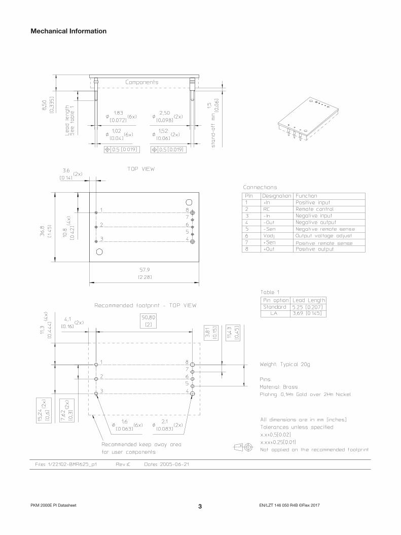
Mechanical Information

EN/LZT 146 050 R4B ©Flex 2017PKM 2000E PI Datasheet
Mechanical Information HS-Option
EN/LZT 146 050 R4B ©Flex 2017PKM 2000E PI Datasheet
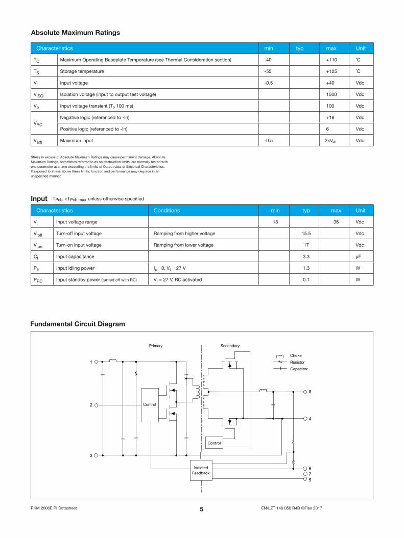
Fundamental Circuit Diagram
Absolute Maximum Ratings
Characteristics Conditions min typ max Unit
VI Input voltage range 18 36 Vdc
VIoff Turn-off input voltage Ramping from higher voltage 15 .5 Vdc
VIon Turn-on input voltage Ramping from lower voltage 17 Vdc
CI Input capacitance 3 .3 µF
PIi Input idling power Io= 0, VI = 27 V 1 .3 W
PRC Input standby power (turned off with RC) VI = 27 V, RC activated 0 .1 W
Input TPcb <TPcb max unless otherwise specified
Characteristics min typ max Unit
TC Maximum Operating Baseplate Temperature (see Thermal Consideration section) -40 +110 ˚C
TS Storage temperature -55 +125 ˚C
VI Input voltage -0 .5 +40 Vdc
VISO Isolation voltage (input to output test voltage) 1500 Vdc
Vtr Input voltage transient (Tp 100 ms) 100 Vdc
VRC
Negative logic (referenced to -In) +18 Vdc
Positive logic (referenced to -In) 6 Vdc
Vadj Maximum input -0 .5 2xVoi Vdc
Stress in excess of Absolute Maximum Ratings may cause permanent damage . Absolute Maximum Ratings, sometimes referred to as no destruction limits, are normally tested with one parameter at a time exceeding the limits of Output data or Electrical Characteristics . If exposed to stress above these limits, function and performance may degrade in an unspecified manner .
1
2
3
8
4
576
EN/LZT 146 050 R4B ©Flex 2017PKM 2000E PI Datasheet
General information .Flex DC/DC converters and DC/DC regulators are designed in accordance with safety standards IEC/EN/UL 60 950, Safety of Information Technology Equipment.
IEC/EN/UL60950 contains requirements to prevent injury or damage due to the following hazards:
• Electrical shock• Energy hazards• Fire• Mechanical and heat hazards• Radiation hazards• Chemical hazards
On-board DC-DC converters are defined as component power supplies . As components they cannot fully comply with the provisions of any Safety requirements without “Conditions of Acceptability” . It is the responsibility of the installer to ensure that the final product housing these components complies with the requirements of all applicable Safety standards and Directives for the final product .
Component power supplies for general use should comply with the requirements in IEC60950, EN60950 and UL60950 “Safety of information technology equipment” .
There are other more product related standards, e .g . IEC61204-7 “Safety standard for power supplies", IEEE802 .3af “Ethernet LAN/MAN Data terminal equipment power”, and ETS300132-2 “Power supply interface at the input to telecommunications equipment; part 2: DC”, but all of these standards are based on IEC/EN/UL60950 with regards to safety .
Flex DC/DC converters and DC/DC regulators are UL 60 950 recognized and certified in accordance with EN 60 950 .
The flammability rating for all construction parts of the products meets UL 94V-0 .
The products should be installed in the end-use equipment, in accordance with the requirements of the ultimate application . Normally the output of the DC/DC converter is considered as SELV (Safety Extra Low Voltage) and the input source must be isolated by minimum Double or Reinforced Insulation from the primary circuit (AC mains) in accordance with IEC/EN/UL 60 950 .
Safety Specification
Isolated DC/DC converters .
The input voltage to the DC/DC regulator is SELV (Safety Extra Low Voltage) and the output remains SELV under normal and abnormal operating conditions .
It is recommended that a slow blow fuse with a rating twice the maximum input current per selected product be used at the input of each DC/DC regulator .
Non-isolated DC/DC regulators .
24 V dc systems .The input voltage to the DC/DC converter is SELV (Safety Extra Low Voltage) and the output remains SELV under normal and abnormal operating conditions .
48 and 60 V dc systems .
If the input voltage to Flex DC/DC converter is 75 V dc or less, then the output remains SELV (Safety Extra Low Voltage) under normal and abnormal operating conditions .
Single fault testing in the input power supply circuit should be performed with the DC/DC converter connected to demonstrate that the input voltage does not exceed 75 V dc .
If the input power source circuit is a DC power system, the source may be treated as a TNV2 circuit and testing has demonstrated compliance with SELV limits and isolation requirements equivalent to Basic Insulation in accordance with IEC/EN/UL 60 950 .
It is recommended that a fast blow fuse with a rating twice the maximum input current per selected product be used at the input of each DC/DC converter . If an input filter is used in the circuit the fuse should be placed in front of the input filter . In the rare event of a component problem in the input filter or in the DC/DC converter that imposes a short circuit on the input source, this fuse will provide the following functions:
• Isolate the faulty DC/DC converter from the input power sourceso as not to affect the operation of other parts of the system .
• Protect the distribution wiring from excessive current and powerloss thus preventing hazardous overheating .
The galvanic isolation is verified in an electric strength test . The test voltage (VISO) between input and output is 1500 Vdc or 2250 Vdc for 60 seconds (refer to product specification) . Leakage current is less than 1µA at nominal input voltage .
EN/LZT 146 050 R4B ©Flex 2017PKM 2000E PI Datasheet
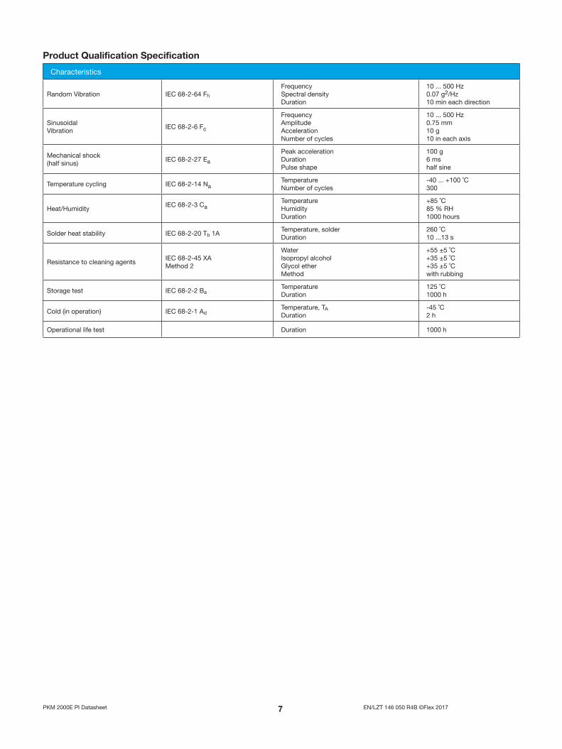
Characteristics
Random Vibration IEC 68-2-64 Fh
Frequency Spectral densityDuration
10 . . . 500 Hz 0 .07 g2/Hz10 min each direction
Sinusoidal Vibration
IEC 68-2-6 Fc
Frequency Amplitude Acceleration Number of cycles
10 . . . 500 Hz 0 .75 mm 10 g 10 in each axis
Mechanical shock (half sinus)
IEC 68-2-27 Ea
Peak acceleration DurationPulse shape
100 g6 mshalf sine
Temperature cycling IEC 68-2-14 NaTemperature Number of cycles
-40 ... +100 ˚C300
Heat/HumidityIEC 68-2-3 Ca
Temperature HumidityDuration
+85 ˚C85 % RH1000 hours
Solder heat stability IEC 68-2-20 Tb 1ATemperature, solderDuration
260 ˚C10 . . .13 s
Resistance to cleaning agentsIEC 68-2-45 XA Method 2
WaterIsopropyl alcohol Glycol etherMethod
+55 ±5 ˚C+35 ±5 ˚C+35 ±5 ˚Cwith rubbing
Storage test IEC 68-2-2 BaTemperature Duration
125 ˚C1000 h
Cold (in operation) IEC 68-2-1 AdTemperature, TADuration
-45 ˚C2 h
Operational life test Duration 1000 h
Product Qualification Specification

EN/LZT 146 050 R4B ©Flex 2017PKM 2000E PI Datasheet
Characteristics Conditions Output Unit
min typ max
VOi
Output voltage initial setting and accuracy
IOmax, VI = 27 V, TPcb = 25 ˚C 3 .23 3 .3 3 .37 V
Output adjust range IOmax, VI = 27 V, TPcb = 25 ˚C 2 .97 3 .63 V
VO
Output voltage tolerance band IO = (0 .1 . . .1 .0) x IOmax 3 .2 3 .4 V
Idling voltage IO = 0 3 .2 3 .4 V
Line regulation IOmax 5 mV
Load regulation IO = (0 .01 . . .1 .0) × IOmax, VI = 27 V 5 mV
VtrLoad transient voltage deviation
IO = (0 .1 . . .1 .0) × IOmax, VI = 27 V, load step = 0 .5 × IOmax ±300 mV
ttr Load transient recovery time IO = (0 .1 . . .1 .0) × IOmax, VI = 27 V, load step = 0 .5 × IOmax 100 µs
tr Ramp-up time IO = (0 .1 . . .1 .0) × IOmax, VI = 27 V (0 .1 . . .0 .9) × VOnom
5 10 ms
ts Start-up time IO = (0 .1 . . .1 .0) × IOmax, VI = 27 V VI connection to 0 .9 x VOnom 7 .5 15 ms
IO Output current 0 15 A
POmax Max output power At VO = VOnom 50 W
Ilim Current limit threshold TPcb < TPcbmax 20 A
Isc Short circuit current TPcb = 25 °C, VO < 0 .5V 27 A
VOac Output ripple & noise See ripple and noise, IOmax, VOnom, 25 50 mVp-p
SVR Supply voltage rejection (ac) TPcb = 25 °C, f = 100 Hz sinewave , 1 Vpp, VI = 27 V 70 dB
OVP Over voltage protection VI = 27 V IO = (0 .1 . . .1 .0) × IOmax 3 .9 5 .0 V
TPcb = -40 . . .+90 ºC and VI = 18 . . .36V, sense pins connected to output pins unless otherwise specified .
PKM 10E PI Output
Miscellaneous
Characteristics Conditions min typ max Unit
η Efficiency - 100% load IOmax, VI = 27 V, TPcb = 25 ˚C 85 87 %
η Efficiency - 50% load IOmax / 2, VI = 27 V, TPcb = 25 ˚C 89 %
Pd Power Dissipation IOmax, VI = 27 V, TPcb = 25 ˚C 7 .3 W
fs Switching frequency 180 kHz
EN/LZT 146 050 R4B ©Flex 2017PKM 2000E PI Datasheet
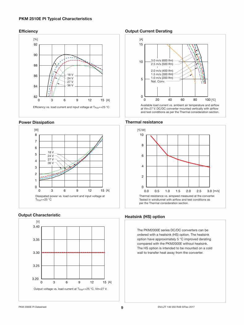
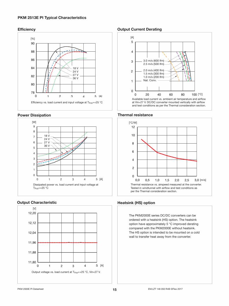
Heatsink (HS) option
The PKM2000E series DC/DC converters can be ordered with a heatsink (HS) option . The heatsink option have approximately 5 °C improved derating compared with the PKM2000E without heatsink . The HS option is intended to be mounted on a cold wall to transfer heat away from the converter .
Efficiency Output Current Derating
PKM 10E PI Typical Characteristics
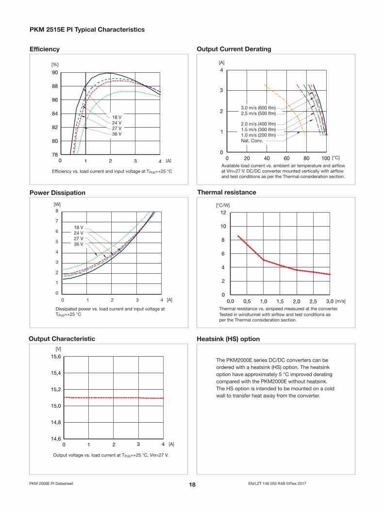
Efficiency vs . load current and input voltage at TPcb=+25 °C
0 20 40 60 80 1000
5
10
15
[°C]
[A]
2.0 m/s (400 lfm)1.5 m/s (300 lfm)1.0 m/s (200 lfm)Nat. Conv.
3.0 m/s (600 lfm) 2.5 m/s (500 lfm)
Output Characteristic
Output voltage vs . load current at TPcb=+25 °C, Vin=27 V .
0 3 6 9 12 153.20
3.25
3.30
3.35
3.40
[A]
[V]
Power Dissipation
0 3 6 9 12 150
1
2
3
4
5
6
7
8
[A]
[W]
18 V24 V27 V36 V
Dissipated power vs . load current and input voltage at TPcb=+25 °C
Thermal resistance
0.0 0.5 1.0 1.5 2.0 2.5 3.00
2
4
6
8
10
[m/s]
[°C/W]
Available load current vs . ambient air temperature and airflow at Vin=27 V . DC/DC converter mounted vertically with airflow and test conditions as per the Thermal consideration section .
Thermal resistance vs . airspeed measured at the converter . Tested in windtunnel with airflow and test conditions as per the Thermal consideration section .
10 EN/LZT 146 050 R4B ©Flex 2017PKM 2000E PI Datasheet
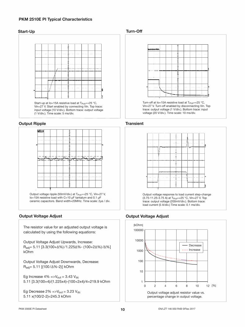
PKM 10E PI Typical Characteristics
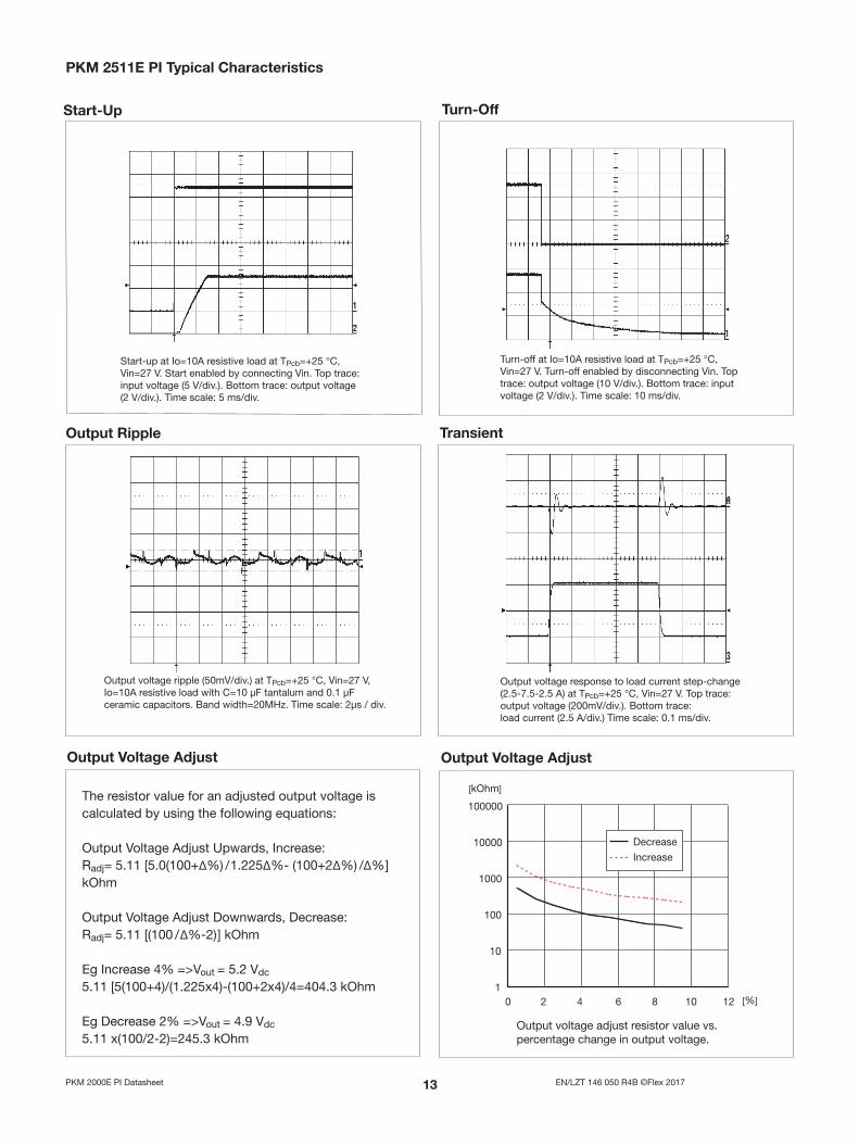
Output Ripple Transient
Output voltage ripple (50mV/div .) at TPcb=+25 °C, Vin=27 V, Io=15A resistive load with C=10 µF tantalum and 0 .1 µF ceramic capacitors . Band width=20MHz . Time scale: 2µs / div .
Output voltage response to load current step-change (3 .75-11 .25-3 .75 A) at TPcb=+25 °C, Vin=27 V . Top trace: output voltage (200mV/div .) . Bottom trace: load current (5 A/div .) Time scale: 0 .1 ms/div .
Output Voltage Adjust
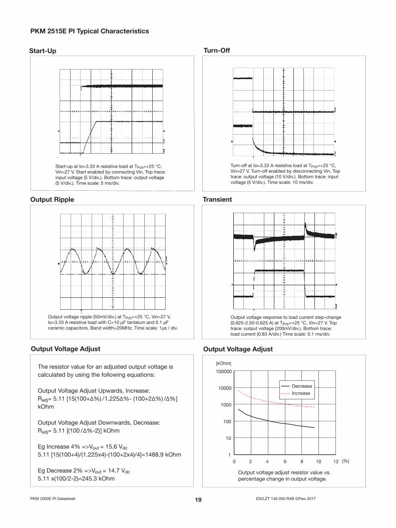
Output voltage adjust resistor value vs . percentage change in output voltage .
Output Voltage Adjust
The resistor value for an adjusted output voltage is calculated by using the following equations:
Output Voltage Adjust Upwards, Increase: Radj= 5 .11 [3 .3(100+Δ%) / 1 .225Δ%- (100+2Δ%) /Δ% ] kOhm
Output Voltage Adjust Downwards, Decrease: Radj= 5 .11 [(100 / Δ%-2) ] kOhm
Eg Increase 4% =>Vout = 3 .43 Vdc
5 .11 [3 .3(100+4)/(1 .225x4)-(100+2x4)/4=219 .9 kOhm
Eg Decrease 2% =>Vout = 3 .23 Vdc
5 .11 x(100/2-2)=245 .3 kOhm
Start-Up Turn-Off
Start-up at Io=15A resistive load at TPcb=+25 °C, Vin=27 V . Start enabled by connecting Vin . Top trace: input voltage (10 V/div .) . Bottom trace: output voltage (1 V/div .) . Time scale: 5 ms/div .
Turn-off at Io=15A resistive load at TPcb=+25 °C, Vin=27 V . Turn-off enabled by disconnecting Vin . Top trace: output voltage (1 V/div .) . Bottom trace: input voltage (20 V/div .) . Time scale: 10 ms/div .

11 EN/LZT 146 050 R4B ©Flex 2017PKM 2000E PI Datasheet
Characteristics Conditions Output Unit
min typ max
VOi
Output voltage initial setting and accuracy
IOmax, VI = 27 V, TPcb = 25 ˚C 4 .89 5 .0 5 .11 V
Output adjust range IOmax, VI = 27 V, TPcb = 25 ˚C 4 .5 5 .5 V
VO
Output voltage tolerance band IO = (0 .1 . . .1 .0) x IOmax 4 .85 5 .15 V
Idling voltage IO = 0 4 .85 5 .15 V
Line regulation IOmax 5 mV
Load regulation IO = (0 .01 . . .1 .0) × IOmax, VI = 27 V 5 mV
VtrLoad transient voltage deviation
IO = (0 .1 . . .1 .0) × IOmax, VI = 27 V, load step = 0 .5 × IOmax ±250 mV
ttr Load transient recovery time IO = (0 .1 . . .1 .0) × IOmax, VI = 27 V, load step = 0 .5 × IOmax 100 µs
tr Ramp-up time IO = (0 .1 . . .1 .0) × IOmax, VI = 27 V (0 .1 . . .0 .9) × VOnom
5 10 ms
ts Start-up time IO = (0 .1 . . .1 .0) × IOmax, VI = 27 V VI connection to 0 .9 x VOnom 7 .5 15 ms
IO Output current 0 10 A
POmax Max output power At VO = VOnom 50 W
Ilim Current limit threshold TPcb < TPcbmax 15 A
Isc Short circuit current TPcb = 25 °C, VO < 0 .5V 25 A
VOac Output ripple & noise See ripple and noise, IOmax, VOnom, 40 60 mVp-p
SVR Supply voltage rejection (ac) TPcb = 25 °C, f = 100 Hz sinewave , 1 Vpp, VI = 27 V 67 dB
OVP Over voltage protection VI = 27 V IO = (0 .1 . . .1 .0) × IOmax 5 .6 7 .6 V
TPcb = -40 . . .+90 ºC and VI = 18 . . .36V, sense pins connected to output pins unless otherwise specified .
PKM 11E PI Output
Miscellaneous
Characteristics Conditions min typ max Unit
η Efficiency - 100% load IOmax, VI = 27 V, TPcb = 25 ˚C 85 87 %
η Efficiency - 50% load IOmax / 2, VI = 27 V, TPcb = 25 ˚C 86 .5 %
Pd Power Dissipation IOmax, VI = 27 V, TPcb = 25 ˚C 7 .5 W
fs Switching frequency 180 kHz
1 EN/LZT 146 050 R4B ©Flex 2017PKM 2000E PI Datasheet
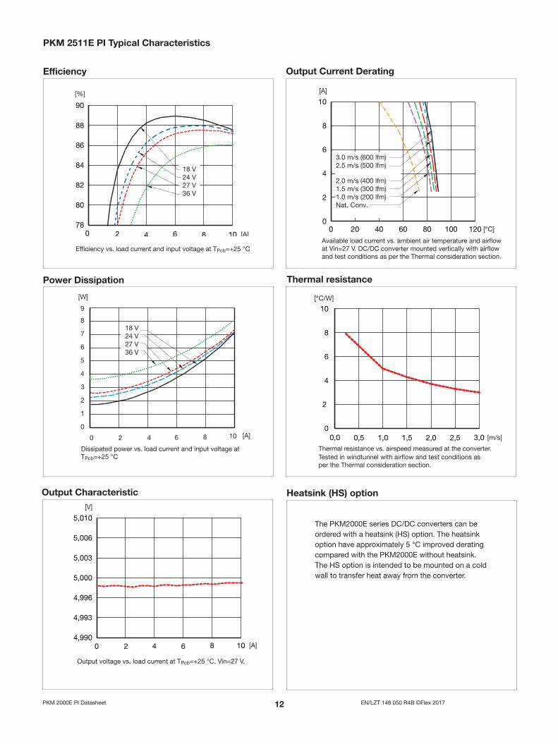
Heatsink (HS) option
The PKM2000E series DC/DC converters can be ordered with a heatsink (HS) option . The heatsink option have approximately 5 °C improved derating compared with the PKM2000E without heatsink . The HS option is intended to be mounted on a cold wall to transfer heat away from the converter .
Efficiency Output Current Derating
PKM 11E PI Typical Characteristics
Efficiency vs . load current and input voltage at TPcb=+25 °C
Output Characteristic
Output voltage vs . load current at TPcb=+25 °C, Vin=27 V .
Power Dissipation
Dissipated power vs . load current and input voltage at TPcb=+25 °C
Thermal resistance
Available load current vs . ambient air temperature and airflow at Vin=27 V . DC/DC converter mounted vertically with airflow and test conditions as per the Thermal consideration section .
Thermal resistance vs . airspeed measured at the converter . Tested in windtunnel with airflow and test conditions as per the Thermal consideration section .
1 EN/LZT 146 050 R4B ©Flex 2017PKM 2000E PI Datasheet
PKM 11E PI Typical Characteristics
Output Ripple Transient
Output voltage ripple (50mV/div .) at TPcb=+25 °C, Vin=27 V, Io=10A resistive load with C=10 µF tantalum and 0 .1 µF ceramic capacitors . Band width=20MHz . Time scale: 2µs / div .
Output voltage response to load current step-change (2 .5-7 .5-2 .5 A) at TPcb=+25 °C, Vin=27 V . Top trace: output voltage (200mV/div .) . Bottom trace: load current (2 .5 A/div .) Time scale: 0 .1 ms/div .
Output Voltage Adjust
Output voltage adjust resistor value vs . percentage change in output voltage .
Output Voltage Adjust
The resistor value for an adjusted output voltage is calculated by using the following equations:
Output Voltage Adjust Upwards, Increase: Radj= 5 .11 [5 .0(100+Δ%) / 1 .225Δ%- (100+2Δ%) /Δ% ] kOhm
Output Voltage Adjust Downwards, Decrease: Radj= 5 .11 [(100 / Δ%-2) ] kOhm
Eg Increase 4% =>Vout = 5 .2 Vdc
5 .11 [5(100+4)/(1 .225x4)-(100+2x4)/4=404 .3 kOhm
Eg Decrease 2% =>Vout = 4 .9 Vdc
5 .11 x(100/2-2)=245 .3 kOhm
Start-Up Turn-Off
Start-up at Io=10A resistive load at TPcb=+25 °C, Vin=27 V . Start enabled by connecting Vin . Top trace: input voltage (5 V/div .) . Bottom trace: output voltage (2 V/div .) . Time scale: 5 ms/div .
Turn-off at Io=10A resistive load at TPcb=+25 °C, Vin=27 V . Turn-off enabled by disconnecting Vin . Top trace: output voltage (10 V/div .) . Bottom trace: input voltage (2 V/div .) . Time scale: 10 ms/div .

1 EN/LZT 146 050 R4B ©Flex 2017PKM 2000E PI Datasheet
Characteristics Conditions Output Unit
min typ max
VOi
Output voltage initial setting and accuracy
IOmax, VI = 27 V, TPcb = 25 ˚C 11 .8 12 .0 12 .2 V
Output adjust range IOmax, VI = 27 V, TPcb = 25 ˚C 10 .8 13 .2 V
VO
Output voltage tolerance band IO = (0 .1 . . .1 .0) x IOmax 11 .74 12 .26 V
Idling voltage IO = 0 11 .74 12 .26 V
Line regulation IOmax 10 mV
Load regulation IO = (0 .01 . . .1 .0) × IOmax, VI = 27 V 10 mV
VtrLoad transient voltage deviation
IO = (0 .1 . . .1 .0) × IOmax, VI = 27 V, load step = 0 .5 × IOmax ±300 mV
ttr Load transient recovery time IO = (0 .1 . . .1 .0) × IOmax, VI = 27 V, load step = 0 .5 × IOmax 100 µs
tr Ramp-up time IO = (0 .1 . . .1 .0) × IOmax, VI = 27 V (0 .1 . . .0 .9) × VOnom
5 10 ms
ts Start-up time IO = (0 .1 . . .1 .0) × IOmax, VI = 27 V VI connection to 0 .9 x VOnom 7 .5 15 ms
IO Output current 0 4 .2 A
POmax Max output power At VO = VOnom 50 W
Ilim Current limit threshold TPcb < TPcbmax 6 .0 A
Isc Short circuit current TPcb = 25 °C, VO < 0 .5V 9 A
VOac Output ripple & noise See ripple and noise, IOmax, VOnom, 80 150 mVp-p
SVR Supply voltage rejection (ac) TPcb = 25 °C, f = 100 Hz sinewave , 1 Vpp, VI = 27 V 65 dB
OVP Over voltage protection VI = 27 V IO = (0 .1 . . .1 .0) × IOmax 14 16 V
TPcb = -40 . . .+90 ºC and VI = 18 . . .36V, sense pins connected to output pins unless otherwise specified .
PKM 1E PI Output
Miscellaneous
Characteristics Conditions min typ max Unit
η Efficiency - 100% load IOmax, VI = 27 V, TPcb = 25 ˚C 86 87 .5 %
η Efficiency - 50% load IOmax / 2, VI = 27 V, TPcb = 25 ˚C 87 %
Pd Power Dissipation IOmax, VI = 27 V, TPcb = 25 ˚C 7 .0 W
fs Switching frequency 200 kHz
1 EN/LZT 146 050 R4B ©Flex 2017PKM 2000E PI Datasheet
Heatsink (HS) option
The PKM2000E series DC/DC converters can be ordered with a heatsink (HS) option . The heatsink option have approximately 5 °C improved derating compared with the PKM2000E without heatsink . The HS option is intended to be mounted on a cold wall to transfer heat away from the converter .
Efficiency Output Current Derating
PKM 1E PI Typical Characteristics
Efficiency vs . load current and input voltage at TPcb=+25 °C
Output Characteristic
Output voltage vs . load current at TPcb=+25 °C, Vin=27 V .
Power Dissipation
Dissipated power vs . load current and input voltage at TPcb=+25 °C
Thermal resistance
Available load current vs . ambient air temperature and airflow at Vin=27 V . DC/DC converter mounted vertically with airflow and test conditions as per the Thermal consideration section .
Thermal resistance vs . airspeed measured at the converter . Tested in windtunnel with airflow and test conditions as per the Thermal consideration section .
1 EN/LZT 146 050 R4B ©Flex 2017PKM 2000E PI Datasheet
PKM 1E PI Typical Characteristics
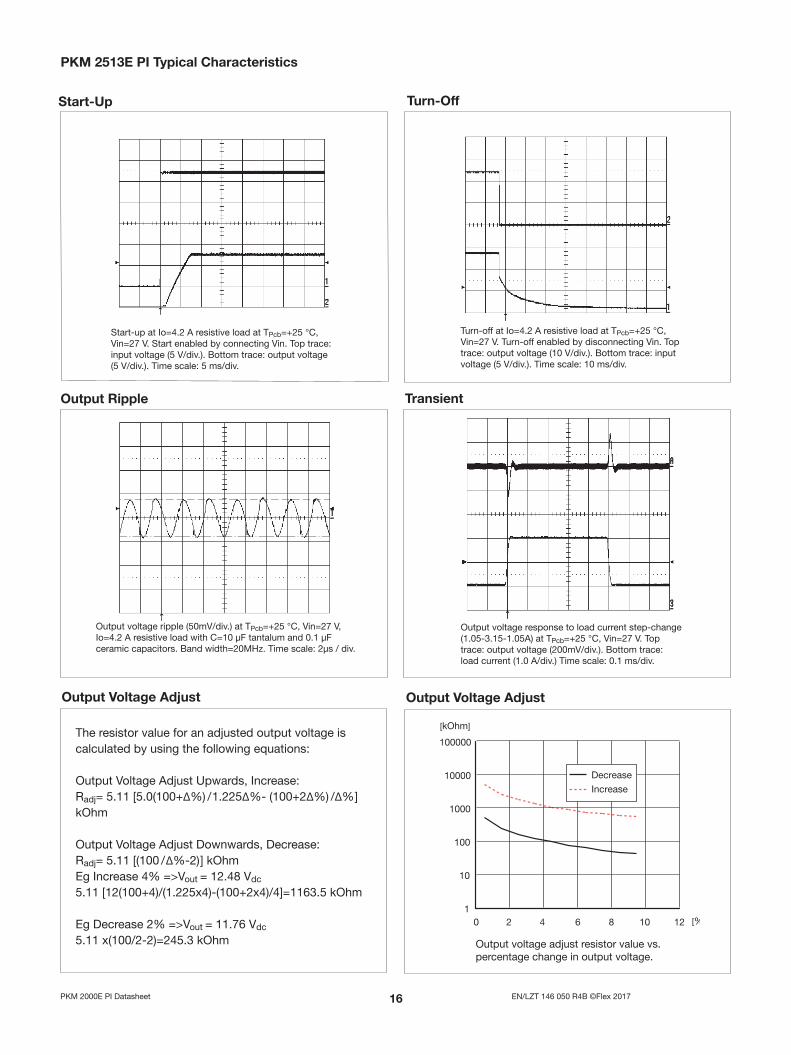
Output Ripple Transient
Output voltage ripple (50mV/div .) at TPcb=+25 °C, Vin=27 V, Io=4 .2 A resistive load with C=10 µF tantalum and 0 .1 µF ceramic capacitors . Band width=20MHz . Time scale: 2µs / div .
Output voltage response to load current step-change (1 .05-3 .15-1 .05A) at TPcb=+25 °C, Vin=27 V . Top trace: output voltage (200mV/div .) . Bottom trace: load current (1 .0 A/div .) Time scale: 0 .1 ms/div .
Output Voltage Adjust
Output voltage adjust resistor value vs . percentage change in output voltage .
Output Voltage Adjust
The resistor value for an adjusted output voltage is calculated by using the following equations:
Output Voltage Adjust Upwards, Increase: Radj= 5 .11 [5 .0(100+Δ%) / 1 .225Δ%- (100+2Δ%) /Δ% ] kOhm
Output Voltage Adjust Downwards, Decrease: Radj= 5 .11 [(100 / Δ%-2) ] kOhmEg Increase 4% =>Vout = 12 .48 Vdc
5 .11 [12(100+4)/(1 .225x4)-(100+2x4)/4]=1163 .5 kOhm
Eg Decrease 2% =>Vout = 11 .76 Vdc
5 .11 x(100/2-2)=245 .3 kOhm
Start-Up Turn-Off
Start-up at Io=4 .2 A resistive load at TPcb=+25 °C, Vin=27 V . Start enabled by connecting Vin . Top trace: input voltage (5 V/div .) . Bottom trace: output voltage (5 V/div .) . Time scale: 5 ms/div .
Turn-off at Io=4 .2 A resistive load at TPcb=+25 °C, Vin=27 V . Turn-off enabled by disconnecting Vin . Top trace: output voltage (10 V/div .) . Bottom trace: input voltage (5 V/div .) . Time scale: 10 ms/div .
1 EN/LZT 146 050 R4B ©Flex 2017PKM 2000E PI Datasheet
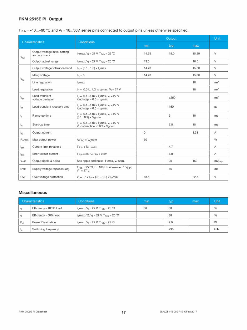
Characteristics Conditions Output Unit
min typ max
VOi
Output voltage initial setting and accuracy
IOmax, VI = 27 V, TPcb = 25 ˚C 14 .75 15 .0 15 .29 V
Output adjust range IOmax, VI = 27 V, TPcb = 25 ˚C 13 .5 16 .5 V
VO
Output voltage tolerance band IO = (0 .1 . . .1 .0) x IOmax 14 .70 15 .30 V
Idling voltage IO = 0 14 .70 15 .30 V
Line regulation IOmax 10 mV
Load regulation IO = (0 .01 . . .1 .0) × IOmax, VI = 27 V 10 mV
VtrLoad transient voltage deviation
IO = (0 .1 . . .1 .0) × IOmax, VI = 27 V, load step = 0 .5 × IOmax ±250 mV
ttr Load transient recovery time IO = (0 .1 . . .1 .0) × IOmax, VI = 27 V, load step = 0 .5 × IOmax 150 µs
tr Ramp-up time IO = (0 .1 . . .1 .0) × IOmax, VI = 27 V (0 .1 . . .0 .9) × VOnom
5 10 ms
ts Start-up time IO = (0 .1 . . .1 .0) × IOmax, VI = 27 V VI connection to 0 .9 x VOnom 7 .5 15 ms
IO Output current 0 3 .33 A
POmax Max output power At VO = VOnom 50 W
Ilim Current limit threshold TPcb < TPcbmax 4 .7 A
Isc Short circuit current TPcb = 25 °C, VO < 0 .5V 6 .8 A
VOac Output ripple & noise See ripple and noise, IOmax, VOnom, 95 150 mVp-p
SVR Supply voltage rejection (ac) TPcb = 25 °C, f = 100 Hz sinewave , 1 Vpp, VI = 27 V 50 dB
OVP Over voltage protection VI = 27 V IO = (0 .1 . . .1 .0) × IOmax 18 .5 22 .5 V
TPcb = -40 . . .+90 ºC and VI = 18 . . .36V, sense pins connected to output pins unless otherwise specified .
PKM 1E PI Output
Miscellaneous
Characteristics Conditions min typ max Unit
η Efficiency - 100% load IOmax, VI = 27 V, TPcb = 25 ˚C 86 88 %
η Efficiency - 50% load IOmax / 2, VI = 27 V, TPcb = 25 ˚C 88 %
Pd Power Dissipation IOmax, VI = 27 V, TPcb = 25 ˚C 7 .0 W
fs Switching frequency 230 kHz
1 EN/LZT 146 050 R4B ©Flex 2017PKM 2000E PI Datasheet
Heatsink (HS) option
The PKM2000E series DC/DC converters can be ordered with a heatsink (HS) option . The heatsink option have approximately 5 °C improved derating compared with the PKM2000E without heatsink . The HS option is intended to be mounted on a cold wall to transfer heat away from the converter .
Efficiency Output Current Derating
PKM 1E PI Typical Characteristics
Efficiency vs . load current and input voltage at TPcb=+25 °C
Output Characteristic
Output voltage vs . load current at TPcb=+25 °C, Vin=27 V .
Power Dissipation
Dissipated power vs . load current and input voltage at TPcb=+25 °C
Thermal resistance
Available load current vs . ambient air temperature and airflow at Vin=27 V . DC/DC converter mounted vertically with airflow and test conditions as per the Thermal consideration section .
Thermal resistance vs . airspeed measured at the converter . Tested in windtunnel with airflow and test conditions as per the Thermal consideration section .
1 EN/LZT 146 050 R4B ©Flex 2017PKM 2000E PI Datasheet
PKM 1E PI Typical Characteristics
Output Ripple Transient
Output voltage ripple (50mV/div .) at TPcb=+25 °C, Vin=27 V, Io=3 .33 A resistive load with C=10 µF tantalum and 0 .1 µF ceramic capacitors . Band width=20MHz . Time scale: 1µs / div .
Output voltage response to load current step-change (0 .625-2 .50-0 .625 A) at TPcb=+25 °C, Vin=27 V . Top trace: output voltage (200mV/div .) . Bottom trace: load current (0 .83 A/div .) Time scale: 0 .1 ms/div .
Output Voltage Adjust
Output voltage adjust resistor value vs . percentage change in output voltage .
Output Voltage Adjust
The resistor value for an adjusted output voltage is calculated by using the following equations:
Output Voltage Adjust Upwards, Increase: Radj= 5 .11 [15(100+Δ%) / 1 .225Δ%- (100+2Δ%) /Δ% ] kOhm
Output Voltage Adjust Downwards, Decrease: Radj= 5 .11 [(100 / Δ%-2) ] kOhm
Eg Increase 4% =>Vout = 15 .6 Vdc
5 .11 [15(100+4)/(1 .225x4)-(100+2x4)/4]=1488 .9 kOhm
Eg Decrease 2% =>Vout = 14 .7 Vdc
5 .11 x(100/2-2)=245 .3 kOhm
Start-Up Turn-Off
Start-up at Io=3 .33 A resistive load at TPcb=+25 °C, Vin=27 V . Start enabled by connecting Vin . Top trace: input voltage (5 V/div .) . Bottom trace: output voltage (5 V/div .) . Time scale: 5 ms/div .
Turn-off at Io=3 .33 A resistive load at TPcb=+25 °C, Vin=27 V . Turn-off enabled by disconnecting Vin . Top trace: output voltage (10 V/div .) . Bottom trace: input voltage (5 V/div .) . Time scale: 10 ms/div .

0 EN/LZT 146 050 R4B ©Flex 2017PKM 2000E PI Datasheet
EMC Specification
The conducted EMI measurement was performed using a module placed directly on the test bench .The fundamental switching frequency is 180 kHz for PKM2510E PI @ VI = 27V, IO = (0 .1 . . .1 .0) x IOmax .
External filter (class B)Required external input filter in order to meet class B in EN 55022, CISPR 22 and FCC part 15J .
Test set-up.
Layout Recommendation
The radiated EMI performance of the DC/DC converter will be optimised by including a ground plane in the PCB area under the DC/DC converter . This approach will re-turn switching noise to ground as directly as possible, with improvements to both emissions and susceptibility . It is also important to consider the stand-off of the PKM 2000E series DC/DC converter . If one ground trace is used, it should be connected to the input return . Alternatively, two ground traces may be used, with the trace under the input side of the DC/DC converter connected to the input return and the trace under the output side of the DC/DC converter con-nected to the output return . Make sure to use appropriate safety isolation spacing between these two return traces . The use of two traces as described will provide the capabil-ity of routing the input noise and output noise back to their respective returns .
Conducted EMI Input terminal value (typ)
Output ripple and noise test setup
Output ripple and noise
The circuit below has been used for the ripple and noise measurements on the PKM 2000E Series DC/DC converters .
PKM 2510 E PI without filter
PKM 2510 E PI with filter
0.68uF0.68uF
3.9nF768uHPO422(Pulse)
0.68uF
3.9nF
47uH
220uF+
+
-
DC/DC
DC Power Source
+
-
5µH 50Ω
5µH 50ΩLISN
LISN
in
in out
out
rcvr
rcvr
50 ohm input
1 m Twisted Pair
50 ohm temination
Optional Connection to Earth Ground
Filter (if used)
Power Module
Resistive Load
Printed Circuit Board
EMC Reciver Computer
BNCConnectorto Scope
CeramicCapacitor
+Vout
+Sense
Trim
-Sense
-Vout
Load
TantalumCapacitor
* Conductor from Vout to capacitors = 50mm [1.97in]
+0.1uF 10uF
1 EN/LZT 146 050 R4B ©Flex 2017PKM 2000E PI Datasheet
Operating Information
Input VoltageThe input voltage range 18…36Vdc meets typical requirements in 24 V DC systems used in communications, avionics, industrial and medical equipment . At input voltages exceeding 36V, the power loss will be higher than at normal input voltage and Tref must be limited to absolute max +110°C . The absolute maximum continuous input voltage is 40Vdc .
Turn-Off Input VoltageThe PKM 2000E Series DC/DC converters monitor the input voltage and will turn on and turn off at predetermined levels . The minimum hysteresis between turn on and turn off input voltage is 2V where the turn on input voltage is the highest .
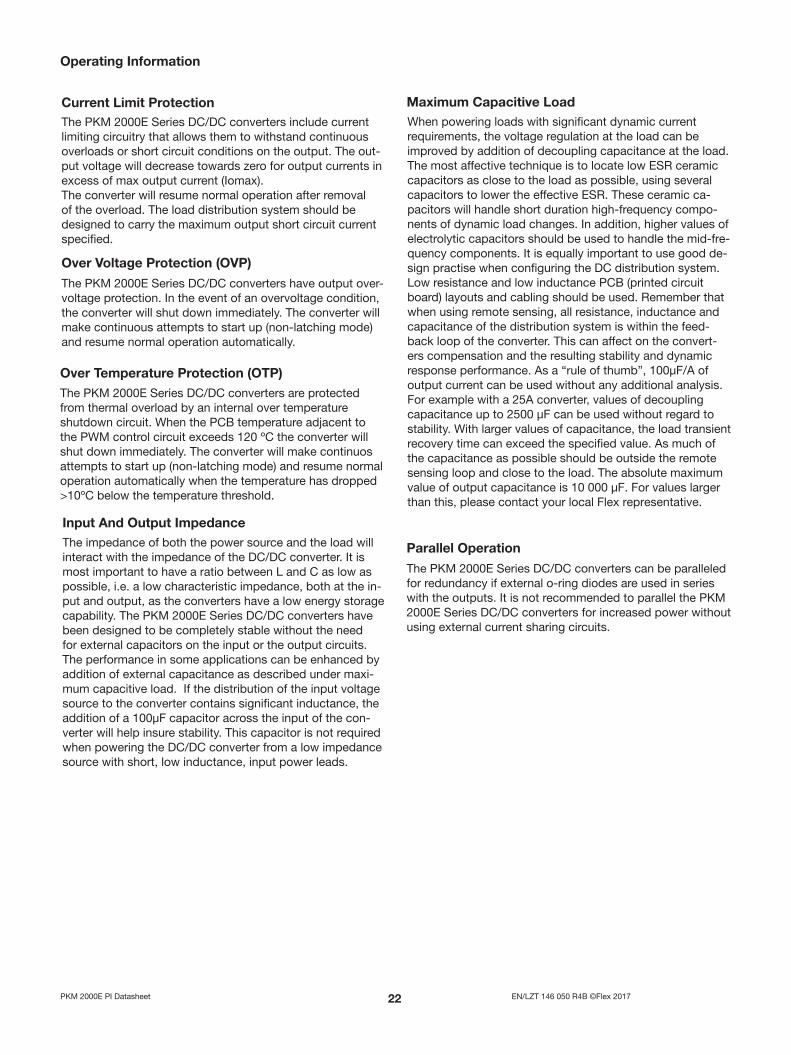
Output Voltage Adjust (Vadj)
All PKM 2000E Series DC/DC converters have an Output Voltage adjust pin (Vadj) . This pin can be used to adjust the output voltage above or below Output voltage initial setting . When increasing the output voltage, the voltage at the output pins (including any remote sense offset) must be kept below the overvoltage trip point, to prevent the converter from shut down . Also note that at increased output voltages the maximum power rating of the converter remains the same, and the output current capability will decrease correspondingly . To decrease the output voltage the resistor should be connected between Vadj pin and –Sense pin . To increase the voltage the resistor should be connected between Vadj pin and +Sense pin . The resistor value of the Output voltage adjust function is according to information given under the output section .
Remote Control (RC)
All PKM 2000E Series DC/DC converters have remote sense that can be used to compensate for moderate amounts of resistance in the distribution system and allow for voltage regulation at the load or other selected point . The remote sense lines will carry very little current and do not need a large cross sectional area . However, the sense lines on the PCB should be located close to a ground trace or ground plane . In a discrete wiring situation, the use of twisted pair wires or other technique to reduce noise susceptibility is highly recommended . The remote sense circuitry will compensate for up to 10% voltage drop between the sense voltage and the voltage at the output pins . The output voltage and the remote sense voltage offset must be less than the minimum over voltage trip point . If the remote sense is not needed the –Sense should be connected to –Out and +Sense should be connected to +Out .
Remote Sense
Circuit configuration for output voltage adjust
+Out
-Out
+Sense
Vadj
-Sense
Load
Radj
Radj
Decrease
Load
Increase
+Out
-Out
+Sense
Vadj
-Sense
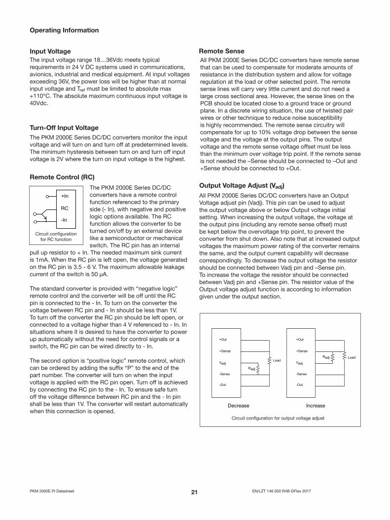
The PKM 2000E Series DC/DC converters have a remote control function referenced to the primary side (- In), with negative and positive logic options available . The RC function allows the converter to be turned on/off by an external device like a semiconductor or mechanical switch . The RC pin has an internal
pull up resistor to + In . The needed maximum sink current is 1mA . When the RC pin is left open, the voltage generated on the RC pin is 3 .5 - 6 V . The maximum allowable leakage current of the switch is 50 µA .
The standard converter is provided with “negative logic” remote control and the converter will be off until the RC pin is connected to the - In . To turn on the converter the voltage between RC pin and - In should be less than 1V . To turn off the converter the RC pin should be left open, or connected to a voltage higher than 4 V referenced to - In . In situations where it is desired to have the converter to power up automatically without the need for control signals or a switch, the RC pin can be wired directly to - In .
The second option is “positive logic” remote control, which can be ordered by adding the suffix “P” to the end of the part number . The converter will turn on when the input voltage is applied with the RC pin open . Turn off is achieved by connecting the RC pin to the - In . To ensure safe turn off the voltage difference between RC pin and the - In pin shall be less than 1V . The converter will restart automatically when this connection is opened .
Circuit configuration for RC function
+In
RC
-In
EN/LZT 146 050 R4B ©Flex 2017PKM 2000E PI Datasheet
Operating Information
Over Temperature Protection (OTP)The PKM 2000E Series DC/DC converters are protected from thermal overload by an internal over temperature shutdown circuit . When the PCB temperature adjacent to the PWM control circuit exceeds 120 ºC the converter will shut down immediately . The converter will make continuos attempts to start up (non-latching mode) and resume normal operation automatically when the temperature has dropped >10ºC below the temperature threshold .
Input And Output ImpedanceThe impedance of both the power source and the load will interact with the impedance of the DC/DC converter . It is most important to have a ratio between L and C as low as possible, i .e . a low characteristic impedance, both at the in-put and output, as the converters have a low energy storage capability . The PKM 2000E Series DC/DC converters have been designed to be completely stable without the need for external capacitors on the input or the output circuits . The performance in some applications can be enhanced by addition of external capacitance as described under maxi-mum capacitive load . If the distribution of the input voltage source to the converter contains significant inductance, the addition of a 100µF capacitor across the input of the con-verter will help insure stability . This capacitor is not required when powering the DC/DC converter from a low impedance source with short, low inductance, input power leads .
Parallel Operation
The PKM 2000E Series DC/DC converters can be paralleled for redundancy if external o-ring diodes are used in series with the outputs . It is not recommended to parallel the PKM 2000E Series DC/DC converters for increased power without using external current sharing circuits .
Maximum Capacitive LoadWhen powering loads with significant dynamic current requirements, the voltage regulation at the load can be improved by addition of decoupling capacitance at the load . The most affective technique is to locate low ESR ceramic capacitors as close to the load as possible, using several capacitors to lower the effective ESR . These ceramic ca-pacitors will handle short duration high-frequency compo-nents of dynamic load changes . In addition, higher values of electrolytic capacitors should be used to handle the mid-fre-quency components . It is equally important to use good de-sign practise when configuring the DC distribution system . Low resistance and low inductance PCB (printed circuit board) layouts and cabling should be used . Remember that when using remote sensing, all resistance, inductance and capacitance of the distribution system is within the feed-back loop of the converter . This can affect on the convert-ers compensation and the resulting stability and dynamic response performance . As a “rule of thumb”, 100µF/A of output current can be used without any additional analysis . For example with a 25A converter, values of decoupling capacitance up to 2500 µF can be used without regard to stability . With larger values of capacitance, the load transient recovery time can exceed the specified value . As much of the capacitance as possible should be outside the remote sensing loop and close to the load . The absolute maximum value of output capacitance is 10 000 µF . For values larger than this, please contact your local Flex representative .
Current Limit Protection The PKM 2000E Series DC/DC converters include current limiting circuitry that allows them to withstand continuous overloads or short circuit conditions on the output . The out-put voltage will decrease towards zero for output currents in excess of max output current (Iomax) .The converter will resume normal operation after removal of the overload . The load distribution system should be designed to carry the maximum output short circuit current specified .
Over Voltage Protection (OVP)
The PKM 2000E Series DC/DC converters have output over-voltage protection . In the event of an overvoltage condition, the converter will shut down immediately . The converter will make continuous attempts to start up (non-latching mode) and resume normal operation automatically .
EN/LZT 146 050 R4B ©Flex 2017PKM 2000E PI Datasheet
Thermal Consideration
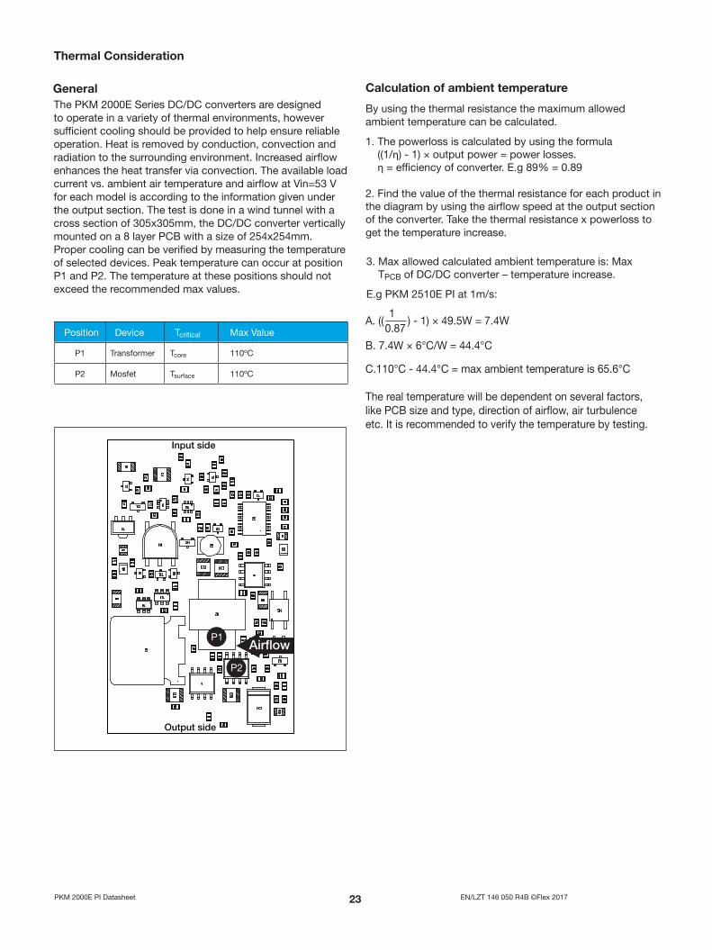
GeneralThe PKM 2000E Series DC/DC converters are designed to operate in a variety of thermal environments, however sufficient cooling should be provided to help ensure reliable operation . Heat is removed by conduction, convection and radiation to the surrounding environment . Increased airflow enhances the heat transfer via convection . The available load current vs . ambient air temperature and airflow at Vin=53 V for each model is according to the information given under the output section . The test is done in a wind tunnel with a cross section of 305x305mm, the DC/DC converter vertically mounted on a 8 layer PCB with a size of 254x254mm . Proper cooling can be verified by measuring the temperature of selected devices . Peak temperature can occur at position P1 and P2 . The temperature at these positions should not exceed the recommended max values .
Calculation of ambient temperature
By using the thermal resistance the maximum allowed ambient temperature can be calculated .
1 . The powerloss is calculated by using the formula ((1/η) - 1) × output power = power losses . η = efficiency of converter . E .g 89% = 0 .89
2 . Find the value of the thermal resistance for each product in the diagram by using the airflow speed at the output section of the converter . Take the thermal resistance x powerloss to get the temperature increase .
3 . Max allowed calculated ambient temperature is: Max TPCB of DC/DC converter – temperature increase .
E .g PKM 2510E PI at 1m/s:
B . 7 .4W × 6°C/W = 44 .4°C
C .110°C - 44 .4°C = max ambient temperature is 65 .6°C
The real temperature will be dependent on several factors, like PCB size and type, direction of airflow, air turbulence etc . It is recommended to verify the temperature by testing .
A . (( ) - 1) × 49 .5W = 7 .4W 1
0 .87 Position Device Tcritical Max Value
P1 Transformer Tcore 110ºC
P2 Mosfet Tsurface 110ºC
EN/LZT 146 050 R4B ©Flex 2017PKM 2000E PI Datasheet
ReliabilityThe Mean Time Between Failure (MTBF) of the PKM2000E Series DC/DC converter is calculated at full output power and an operating ambient temperature (TA) of +40°C . Different methods could be used to calculate the predicted MTBF and failure rate which may give different results . Flex currently uses two different methods, Ericsson failure rate data system DependTool and Telcordia SR332 .
Predicted MTBF for the PKM2000E Series products is:7 .0 million hours according to DependTool .1 .6 million hours according to Telcordia SR332, issue 1,Black box techique .
The Flex failure rate data system is based on field tracking data . The data corresponds to actual failure rates of components used in Information Technology and Telecom (IT&T) equipment in temperature controlled environments (TA = -5 . . .+65°C) . Telcordia SR332 is a commonly used standard method intended for reliability calculations in IT&T equipment .The parts count procedure used in this method was originally modeled on the methods from MIL-HDBK- 217F, ReliabilityPredictions of Electronic Equipment . It assumes that no reliability data is available on the actual units and devices for which the predictions are to be made, i .e . all predictions are based onbased on generic rgeneric reliabilityeliability parameters .equipment . ForFor mormore informatione information please rplease referefer toto Design Note 002 .
Delivery Package Information
The PKM2000E Series DC/DC converters are intended for through hole mounting on a PCB . When wave soldering is used max temperature on the pins is specified to 260°C for 10 seconds . Maximum preheat rate of 4°C/s and temperature of max 130°C is suggested . When hand soldering, care should be taken to avoid direct contact between the hot soldering iron tip and the pins for more than a few seconds in order to prevent overheating .
No-clean flux is recommended to avoid entrapment of cleaning fluids in cavities inside of the DC/DC power module . The residues may affect long time reliability and isolation voltage .
Compatibility with RoHS requirements
Soldering Information
PKM 2000E series standard delivery packages are 100 or 20 pcs boxes (One box contains 5 or 1 full tray(s) and 1 empty hold down tray) .
Tray Specification Material: Polystyrene (PS) Max surface resistance: 10 MOhm/sq Color: Black Capacity: 20 pcs/tray Loaded tray stacking pitch: 16 .2 mm (0 .64 In)Weight: 133 g
The products are compatible with the relevant clauses and requirements of the RoHS directive 2002/95/EC and have a maximum concentration value of 0 .1% by weight in homogeneous materials for lead, mercury, hexavalent chromium, PBB and PBDE and of 0 .01% by weight in homogeneous materials for cadmium .
Exemptions in the RoHS directive utilized in Flex products include: • Lead in high melting temperature type solder (used tosolder the die in semiconductor packages)• Lead in glass of electronics components and in electronicceramic parts (e .g . fill material in chip resistors)• Lead as an alloying element in copper alloy containing up to4% lead by weight (used in connection pins made of Brass)