Embed Size (px)
Citation preview
Split Air ConditionerUser Manual
BK 5200BK 6300

This appliance is not intended for use by persons (including children) with reduced physical, sensoryor mental capabilities or lack of experience and knowledge, unless they have been given supervision or instruction concerning use of the appliance by a person responsible for their safety.Children should be supervised to ensure they are away from the appliance.
Do not dispose this product as unsorted municipal waste. Collection of such waste separately for special treatment is necessary.
ContentOperation NoticesPrecautions............................................................................................................1Parts name ............................................................................................................2Screen Operation GuideButtons on remote controller .................................................................................3Introduction for icons on display screen ................................................................3Introduction for buttons on remote controller.........................................................4Function introduction for combination buttons.......................................................8Operation guide.....................................................................................................9Replacement of batteries in remote controller.......................................................9Emergency operation ..........................................................................................10MaintenanceClean and maintenance.......................................................................................10MalfunctionMalfunction analysis ............................................................................................13Installation NoticeInstallation dimension diagram............................................................................17Tools for installation.............................................................................................18Selection of installation location ..........................................................................18Requirements for electric connection ..................................................................19InstallationInstallation of indoor unit......................................................................................20Installation of outdoor unit ...................................................................................25Vacuum pumping.................................................................................................28Leakage detection ...............................................................................................28Check after installation ........................................................................................29Test and operationTest operation......................................................................................................29Attachment
.........................................................................30Pipe expanding method.......................................................................................32
1
Precautions
Warning
cause electric shock.
may be broken.
damage. Please contact dealer when you need to repair air conditioner.
person can perform the work. Otherwise, it may cause personal injury or damage.
damage or personal injury.
personal injury or damage.
electric shock.
Otherwise, it may cause personal injury or damage.
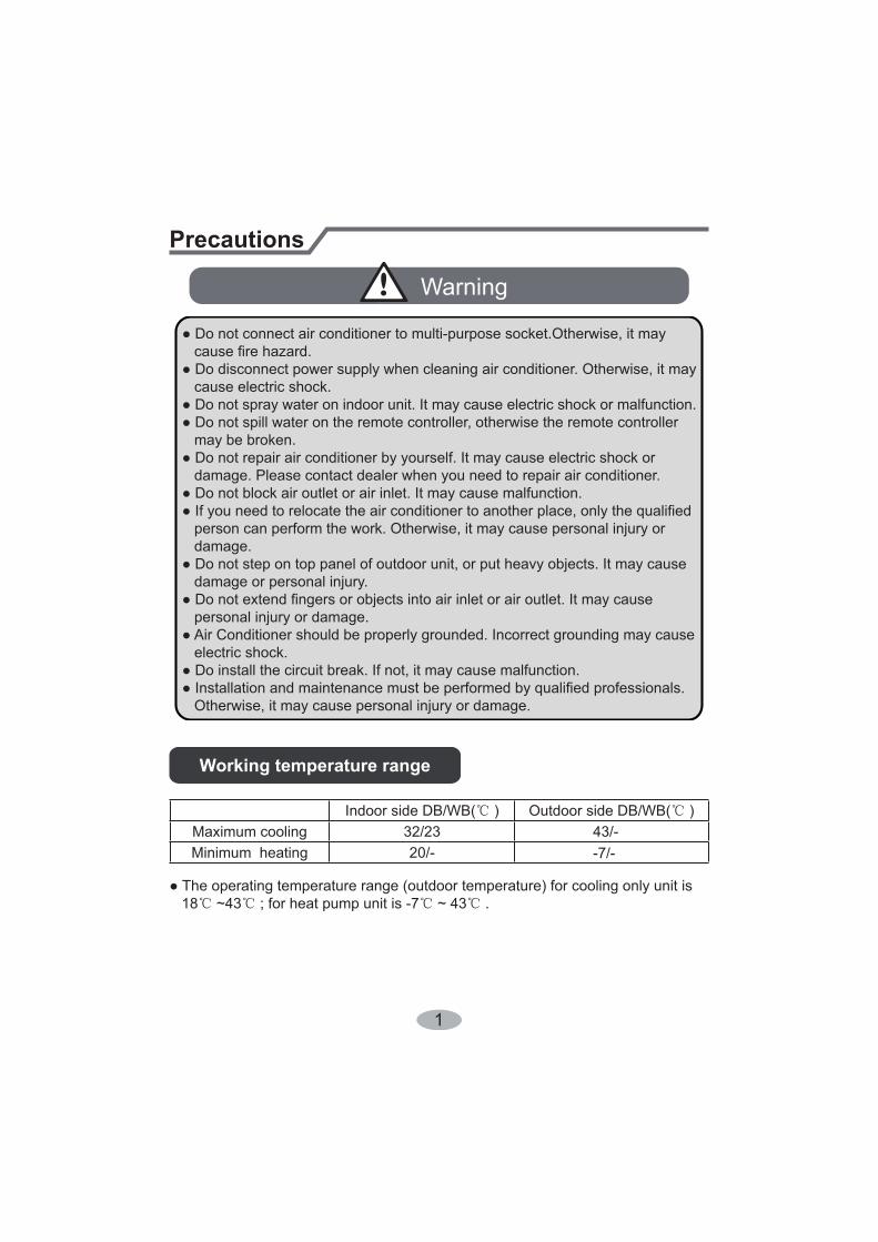
Working temperature range
Indoor side DB/WB( ) Outdoor side DB/WB( )/-3432/23gniloocmumixaM
-7/--/02gnitaehMinimum
18 ~43 ; for heat pump unit is -7 ~ 43 .
2
(Display content or position may be different from above graphics, please refer to actual products)
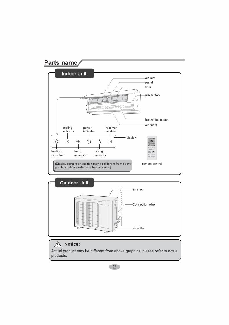
Parts nameIndoor Unit
Outdoor Unit
air inletpanel
aux.button
air outlet
heatingindicator
temp.indicator
coolingindicator
powerindicator
receiverwindow
dryingindicator
display
remote control
Notice:
products.
air inlet
Connection wire
air outlet
3
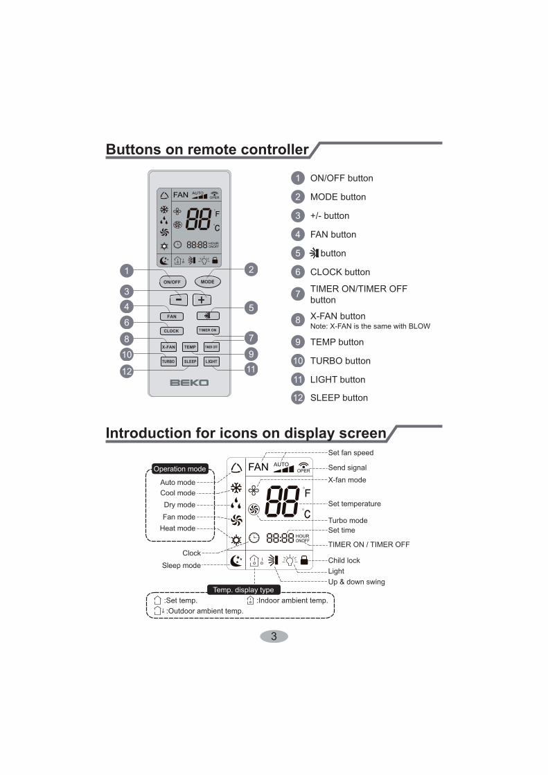
Buttons on remote controller
Introduction for icons on display screen
1
2
5
7
911
10
12
8
6
43
1
2
3
4
5
6
7
8
9
10
11
12
ON/OFF button
MODE button
button
TEMP button
TURBO button
LIGHT button
SLEEP button
TIMER ON/TIMER OFFbutton
CLOCK button
Send signal
Turbo mode
Set temperature
Set time
TIMER ON / TIMER OFF
Child lock
Up & down swing
Set fan speed
Light
Temp. display type:Set temp.:Outdoor ambient temp.
:Indoor ambient temp.
Sleep mode
Clock
Heat modeFan modeDry mode
Cool mode
Operation mode
4
fan blowing angle.
blowing angle.
be adjusted. Press " " button to adjust fan blowing angle.
" " button to adjust fan blowing angle.
Note:
minutes to blow air (actual delay time is depend on indoor ambient temperature).; Fan speed: auto, low
speed, medium speed, high speed.
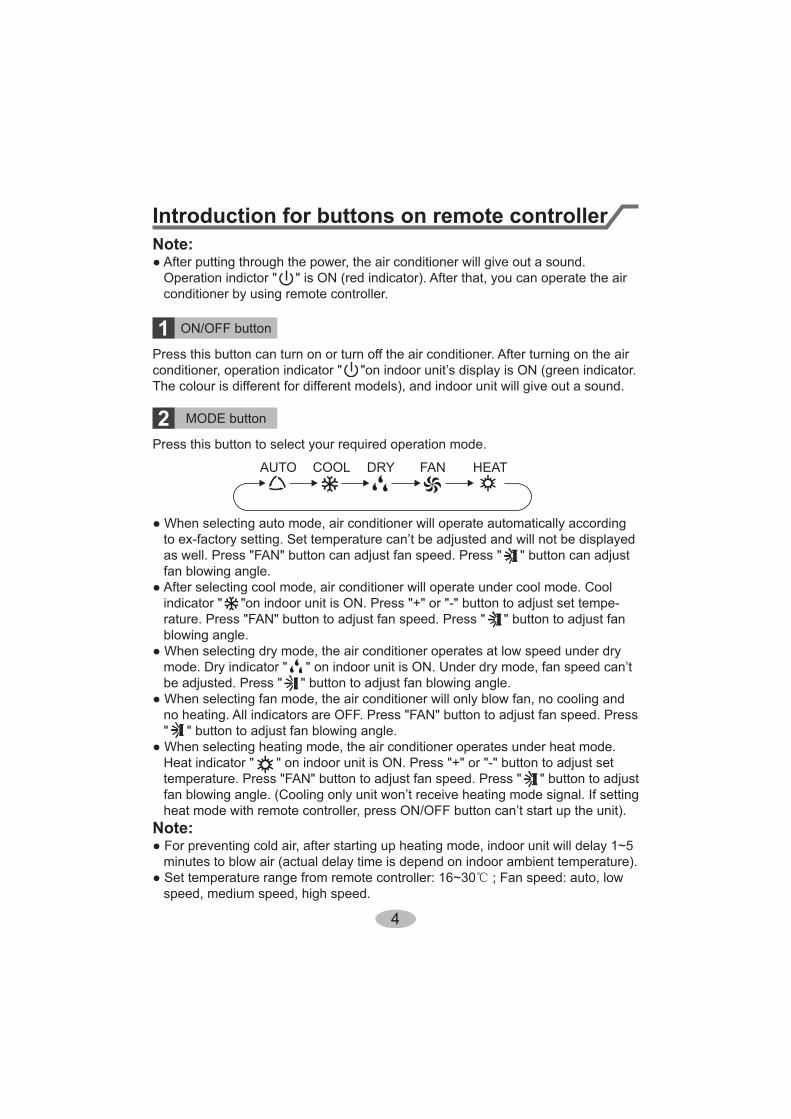
Introduction for buttons on remote controllerNote:
conditioner by using remote controller.
ON/OFF button
MODE button
1
2The colour is different for different models), and indoor unit will give out a sound.
Press this button to select your required operation mode.
COOL DRY
5
Introduction for buttons on remote controller
4
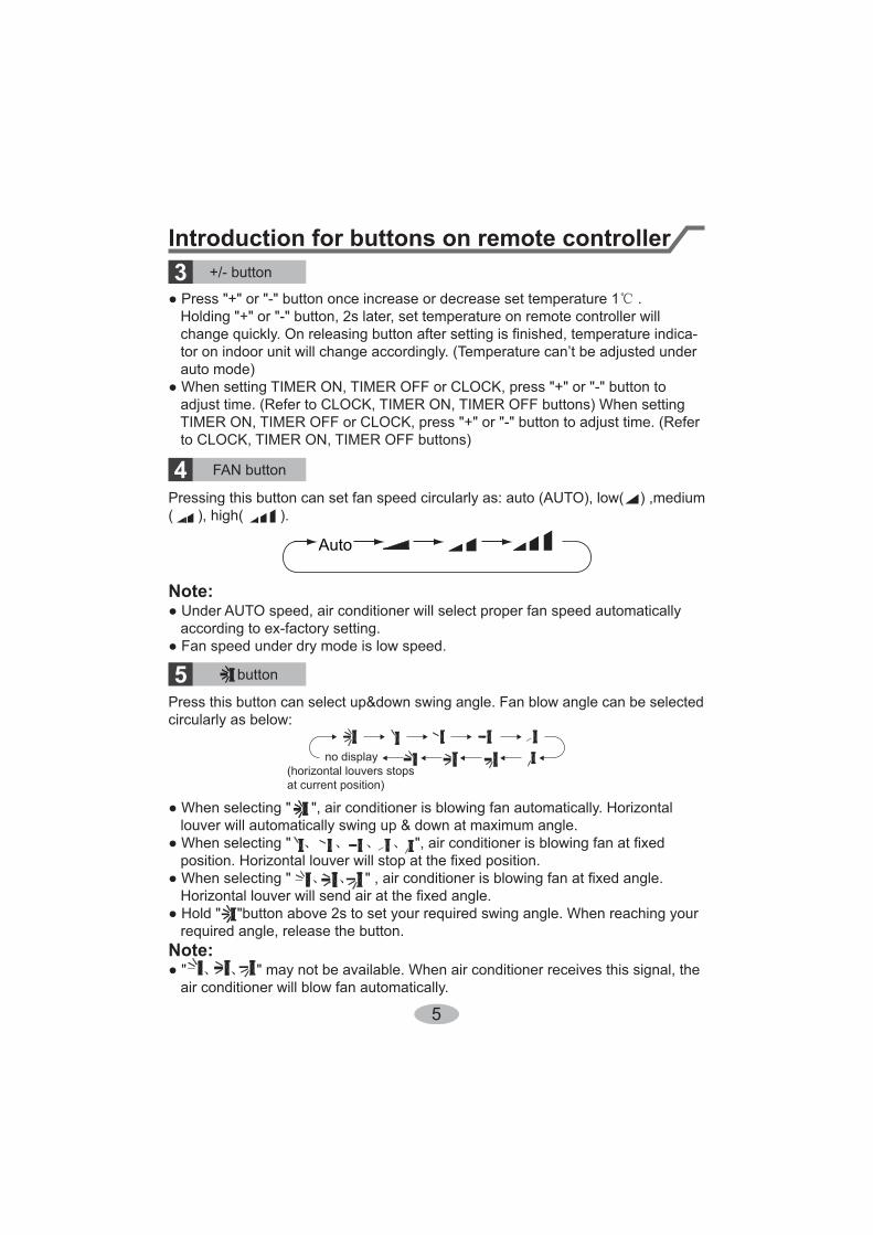
( ), high( ).
Auto
Note:
5Press this button can select up&down swing angle. Fan blow angle can be selectedcircularly as below:
louver will automatically swing up & down at maximum angle.
required angle, release the button.Note:
" may not be available. When air conditioner receives this signal, the air conditioner will blow fan automatically.
button
no display
at current position)
3.
auto mode)
adjust time. (Refer to CLOCK, TIMER ON, TIMER OFF buttons) When setting
to CLOCK, TIMER ON, TIMER OFF buttons)
6
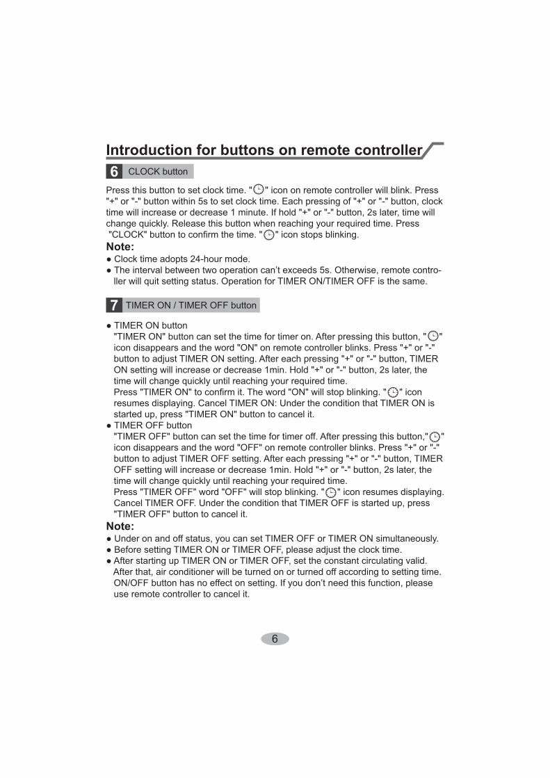
Press this button to set clock time. " " icon on remote controller will blink. Press
change quickly. Release this button when reaching your required time. Press
Note:
ller will quit setting status. Operation for TIMER ON/TIMER OFF is the same.
CLOCK button6Introduction for buttons on remote controller
TIMER ON / TIMER OFF button7
time will change quickly until reaching your required time.
resumes displaying. Cancel TIMER ON: Under the condition that TIMER ON is started up, press "TIMER ON" button to cancel it.
time will change quickly until reaching your required time. Press "TIMER OFF" word "OFF" will stop blinking. " " icon resumes displaying. Cancel TIMER OFF. Under the condition that TIMER OFF is started up, press "TIMER OFF" button to cancel it.Note:
use remote controller to cancel it.
7
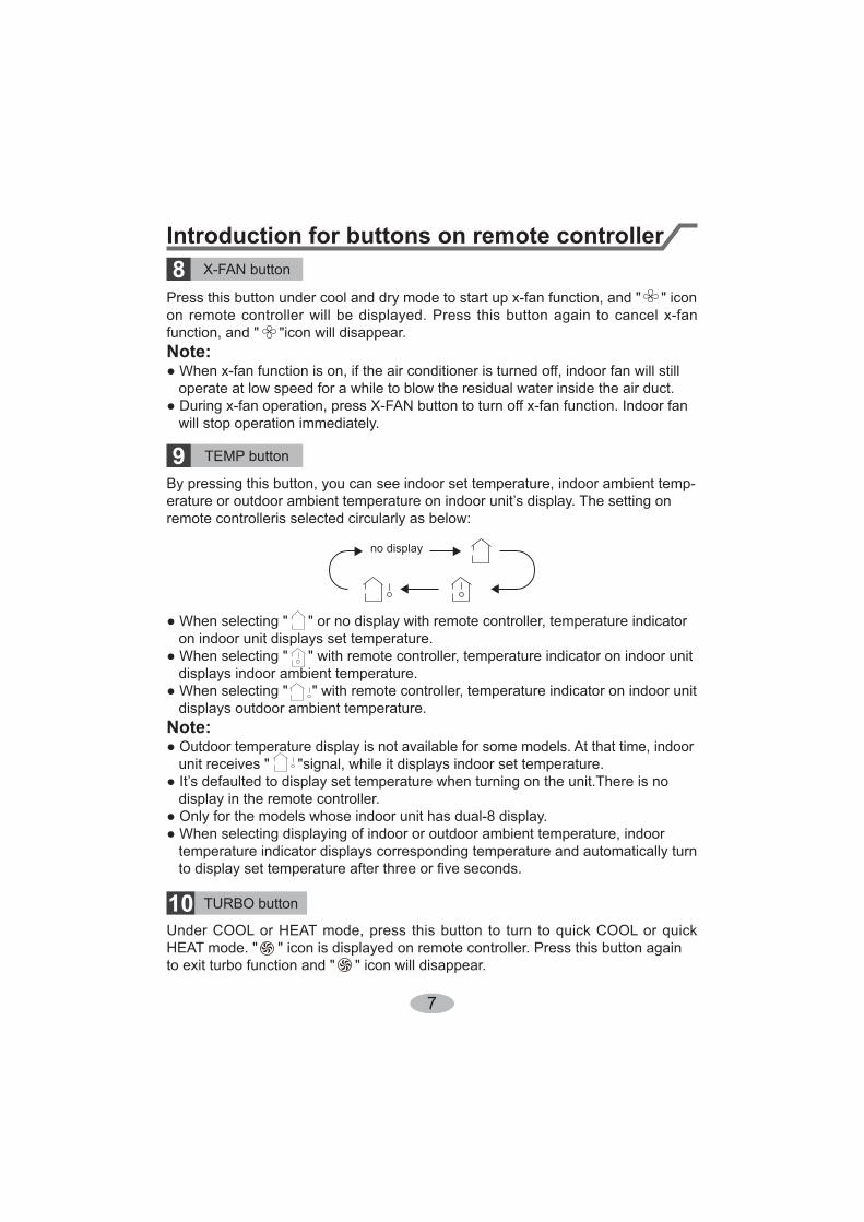
TEMP button9
Introduction for buttons on remote controller
remote controlleris selected circularly as below:
no display
on indoor unit displays set temperature.
displays indoor ambient temperature.
displays outdoor ambient temperature.Note:
unit receives " "signal, while it displays indoor set temperature.
display in the remote controller.
temperature indicator displays corresponding temperature and automatically turn
8
function, and " "icon will disappear.Note:
operate at low speed for a while to blow the residual water inside the air duct.
will stop operation immediately.
TURBO button10
to exit turbo function and " " icon will disappear.
8
Function introduction for combination buttonsChild lock function
child lock function is on, " " icon is displayed on remote controller. If you operatethe remote controller, the " " icon will blink three times without sending signal tothe unit.
Temperature display switchover function
erature display between and .
Introduction for buttons on remote controller
Press this button to turn off display light on indoor unit. " " icon on remote controller disappears. Press this button again to turn on display light. " " icon is displayed.
" " icon is displayed on remote controller. Press this button again to cancel sleepfunction and " " icon will disappear.
SLEEP button
LIGHT button
11
12
9
1. turn on the air conditioner.2.
3. adjusted under auto mode).4. speed.5. Press " " button to select fan blowing angle.
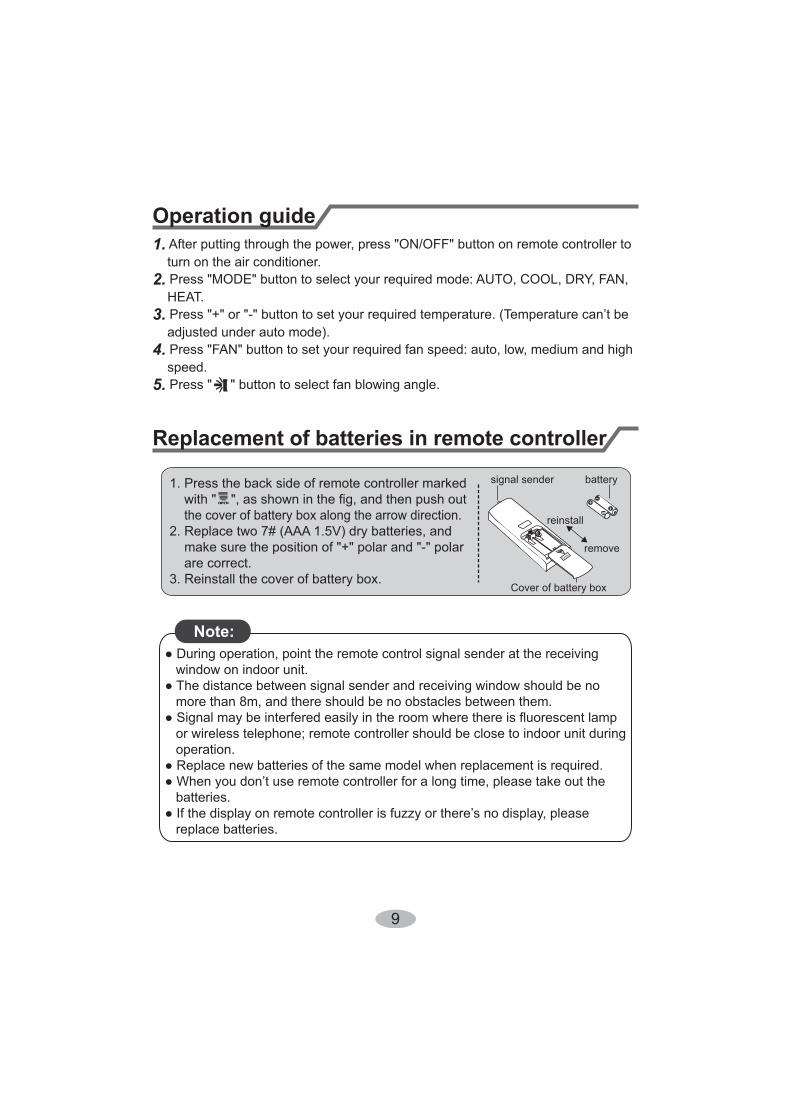
Operation guide
Replacement of batteries in remote controller
1. Press the back side of remote controller marked
the cover of battery box along the arrow direction.
are correct.3. Reinstall the cover of battery box.
signal sender battery
Cover of battery box
remove
reinstall
Note:
window on indoor unit.
more than 8m, and there should be no obstacles between them.
or wireless telephone; remote controller should be close to indoor unit during operation.
batteries.
replace batteries.
10
Emergency operation
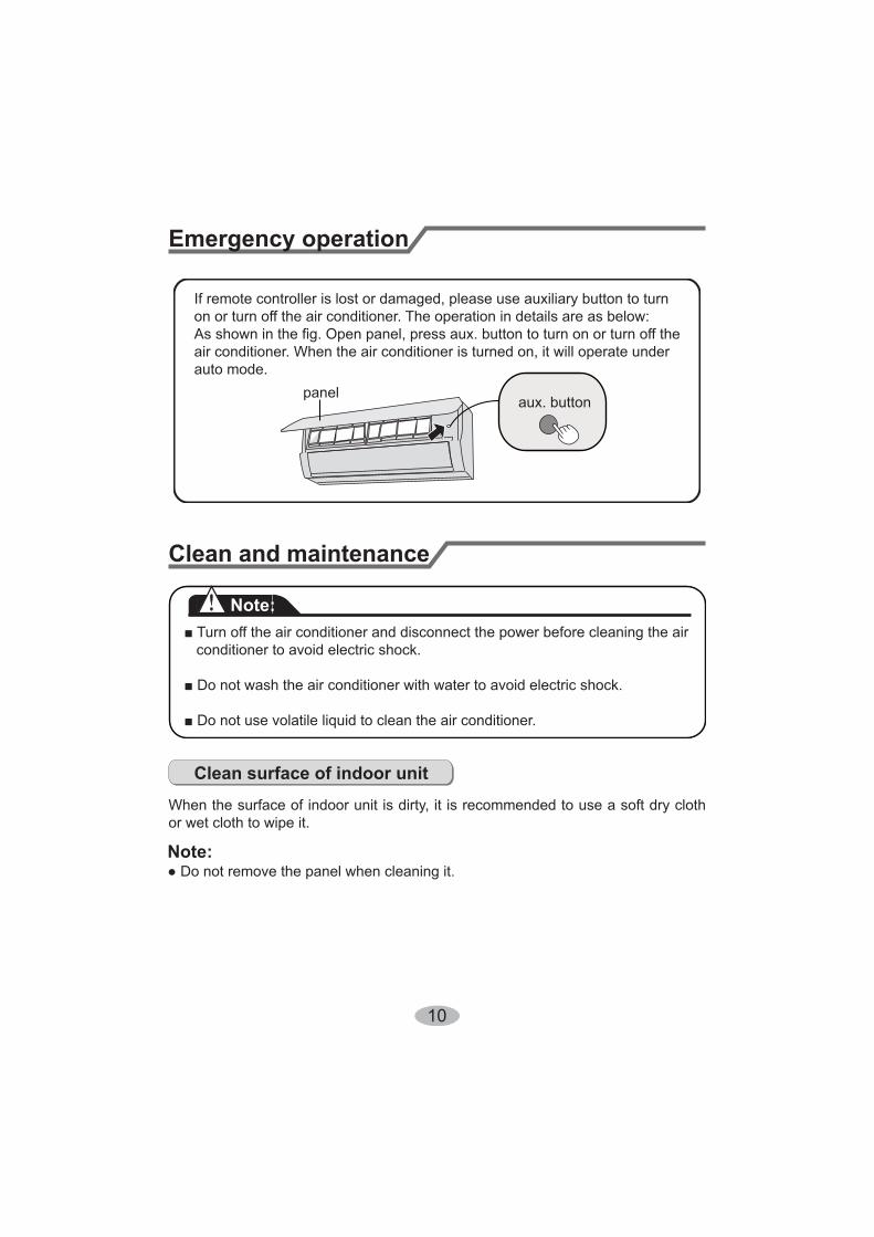
If remote controller is lost or damaged, please use auxiliary button to turnon or turn off the air conditioner. The operation in details are as below:
air conditioner. When the air conditioner is turned on, it will operate underauto mode.
aux. buttonpanel
Clean and maintenance
Note:
conditioner to avoid electric shock.
Clean surface of indoor unit
When the surface of indoor unit is dirty, it is recommended to use a soft dry cloth or wet cloth to wipe it.
Note:
11
Clean and maintenance
1
2
3
4
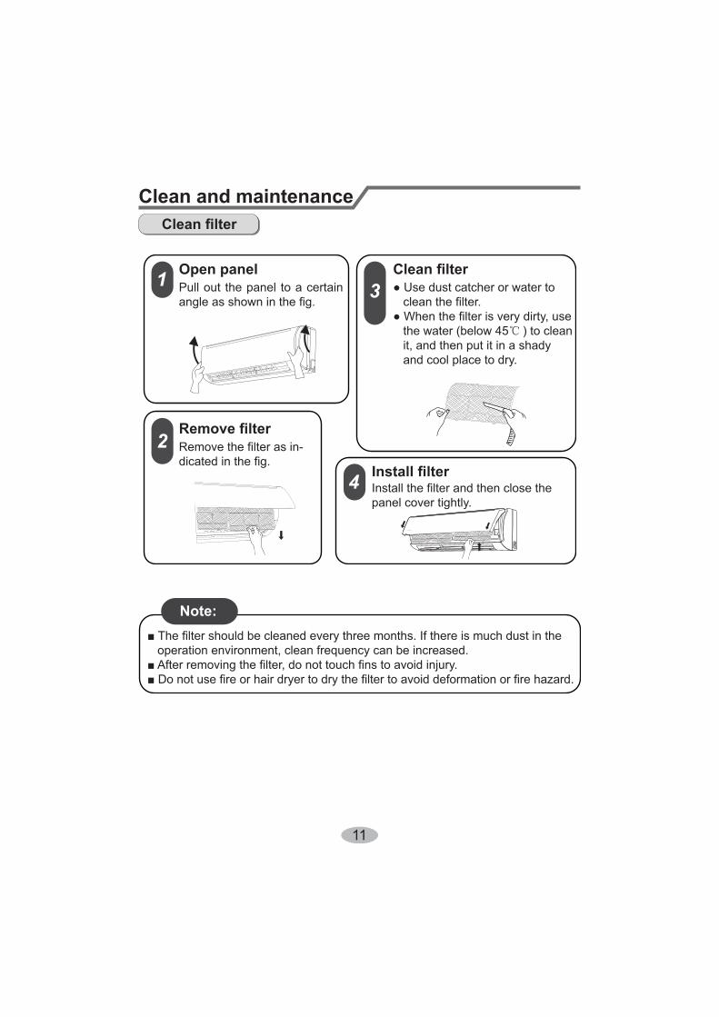
Open panelPull out the panel to a certain
the water (below 45 ) to clean it, and then put it in a shady and cool place to dry.
panel cover tightly.
Note:
operation environment, clean frequency can be increased.
12
Clean and maintenance
Checking before use-season
Checking after use-season
1. Check whether air inlets and air outlets are blocked.2. Check whether circuit break, plug and socket are in good condition.
4. Check whether mounting bracket for outdoor unit is damaged or corroded. If yes, please contact dealer.5. Check whether drainage pipe is damaged.
1. Disconnect power supply.
3. Check whether mounting bracket for outdoor unit is damaged or corroded. If yes, please contact dealer.
Notice for recovery1. Many packing materials are recyclable materials. Please dispose them in appropriate recycling unit.2. If you want to dispose the air conditioner, please contact local dealer or consultant service center for the correct disposal method.
13
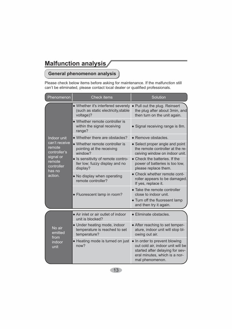
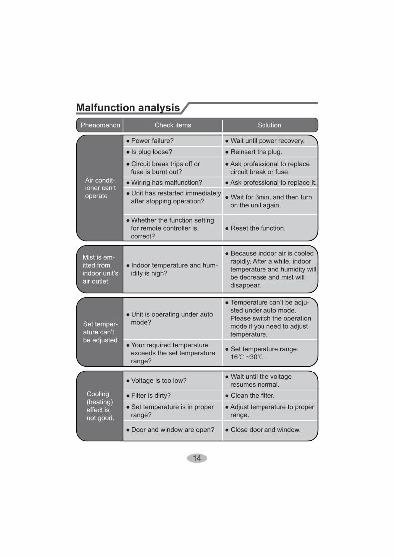
Malfunction analysisGeneral phenomenon analysis
Please check below items before asking for maintenance. If the malfunction still
Phenomenon Check items Solution
Indoor unit
remote
signal orremotecontrollerhas noaction.
(such as static electricity,stable voltage)?
within the signal receiving range?
pointing at the receiving window?
display?
remote controller?
the plug after about 3min, and then turn on the unit again.
Select proper angle and point the remote controller at the re- ceiving window on indoor unit.
power of batteries is too low, please replace them.
close to indoor unit.
and then try it again.
roller appears to be damaged. If yes, replace it.
No air emittedfromindoorunit
unit is blocked?
temperature is reached to set temperature?
ature, indoor unit will stop bl- owing out air.
now? out cold air, indoor unit will be started after delaying for sev- eral minutes, which is a nor- mal phenomenon.
14
Malfunction analysis
fuse is burnt out?
after stopping operation?
for remote controller is correct?
on the unit again.
circuit break or fuse.
operate
Mist is em-itted from
air outlet idity is high? temperature and humidity will
be decrease and mist will disappear.
Phenomenon Check items Solution
Set temper-
be adjusted
mode?
sted under auto mode. Please switch the operation mode if you need to adjust temperature.
exceeds the set temperature range? 16 ~30 .
Cooling(heating)effect is not good.
resumes normal.
range? range.
15
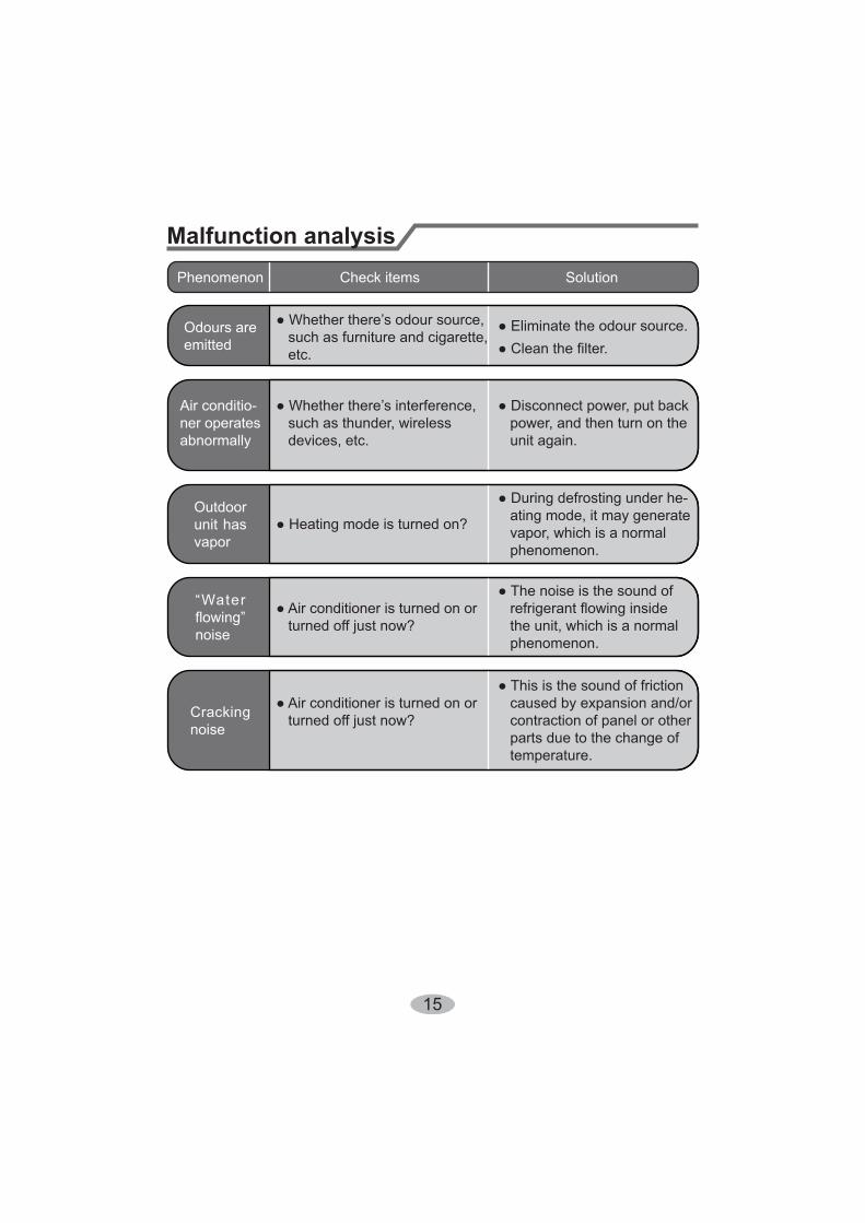
Phenomenon Check items Solution
Odours are emitted such as furniture and cigarette,
etc.
ner operates abnormally
such as thunder, wireless devices, etc.
power, and then turn on the unit again.
Outdoorunit has vapor
ating mode, it may generate vapor, which is a normal phenomenon.
“Water
noise turned off just now? the unit, which is a normal phenomenon.
Cracking noise turned off just now?
caused by expansion and/or contraction of panel or other parts due to the change of temperature.
Malfunction analysis
16
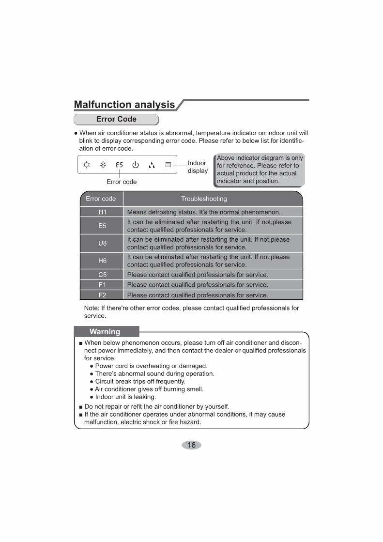
Malfunction analysisError Code
ation of error code.
Indoordisplay
Error code
for reference. Please refer to actual product for the actualindicator and position.
for service.
Warning
Error code
H1
E5
H6
C5F1F2
Troubleshooting
It can be eliminated after restarting the unit. If not,please
It can be eliminated after restarting the unit. If not,please
It can be eliminated after restarting the unit. If not,please
service.
17
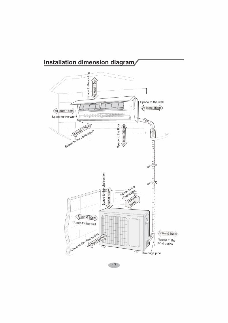
Installation dimension diagram
Drainage pipe
30cmSpa
ce to
the
obst
ruct
ion
Space to the obstruction
Space to the
obstruction
Spac
e to
the
ceilin
g
Space to the obstruction
Space to the obstruction
Space to the wall
Space to the wall
Space to the wall
18
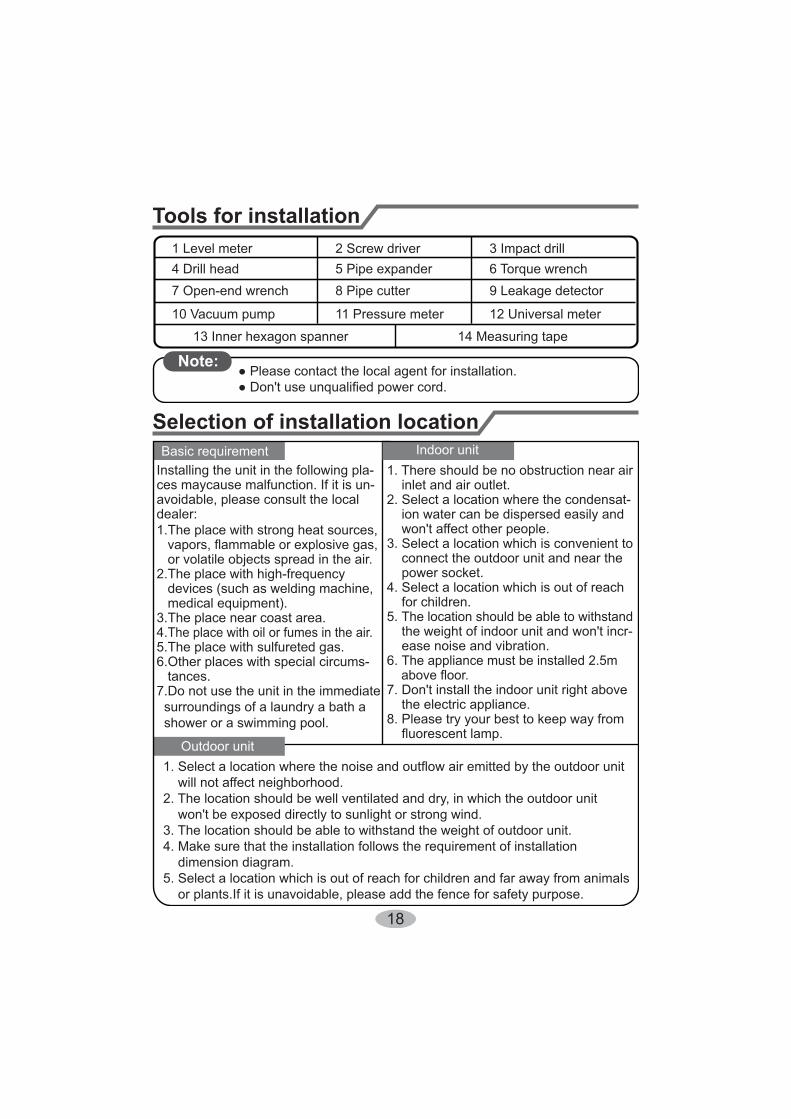
1. There should be no obstruction near air inlet and air outlet.2. Select a location where the condensat- ion water can be dispersed easily and
3. Select a location which is convenient to connect the outdoor unit and near the power socket.4. Select a location which is out of reach for children.5. The location should be able to withstand
ease noise and vibration.6. The appliance must be installed 2.5m
the electric appliance.8. Please try your best to keep way from
Tools for installation
Selection of installation location
1 Level meter 2 Screw driver 3 Impact drill4 Drill head 5 Pipe expander 6 Torque wrench7 Open-end wrench 8 Pipe cutter 9 Leakage detector
10 Vacuum pump 11 Pressure meter
13 Inner hexagon spanner 14 Measuring tape
Note:
Basic requirement
Outdoor unit
Indoor unitInstalling the unit in the following pla-ces maycause malfunction. If it is un-avoidable, please consult the localdealer:1.The place with strong heat sources,
, or volatile objects spread in the air.2.The place with high-frequency devices (such as welding machine, medical equipment).3.The place near coast area.4.The place with oil or fumes in the air.5.The place with sulfureted gas.6.Other places with special circums- tances.7.Do not use the unit in the immediate surroundings of a laundry a bath a shower or a swimming pool.
will not affect neighborhood.2. The location should be well ventilated and dry, in which the outdoor unit
3. The location should be able to withstand the weight of outdoor unit.4. Make sure that the installation follows the requirement of installation dimension diagram.5. Select a location which is out of reach for children and far away from animals or plants.If it is unavoidable, please add the fence for safety purpose.
19
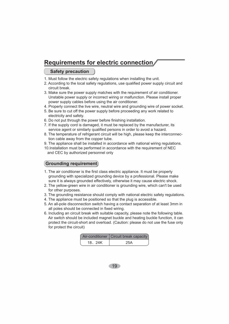
Requirements for electric connectionSafety precaution
Grounding requirement
1. Must follow the electric safety regulations when installing the unit.
circuit break.3. Make sure the power supply matches with the requirement of air conditioner.
power supply cables before using the air conditioner.4. Properly connect the live wire, neutral wire and grounding wire of power socket.5. Be sure to cut off the power supply before proceeding any work related to electricity and safety.
7. If the supply cord is damaged, it must be replaced by the manufacturer, its
8. The temperature of refrigerant circuit will be high, please keep the interconnec- tion cable away from the copper tube.9. The appliance shall be installed in accordance with national wiring regulations.10.Installation must be performed in accordance with the requirement of NEC
sure it is always grounded effectively, otherwise it may cause electric shock.
for other purposes.3. The grounding resistance should comply with national electric safety regulations.4. The appliance must be positioned so that the plug is accessible.
6. Including an circuit break with suitable capacity, please note the following table.
protect the circuit-short and overload. (Caution: please do not use the fuse only for protect the circuit)
Circuit break capacity18 24K
20
Installation of indoor unitStep one: choosing installation location
Step two: install wall-mounting frame
plastic expansion particles in the holes.
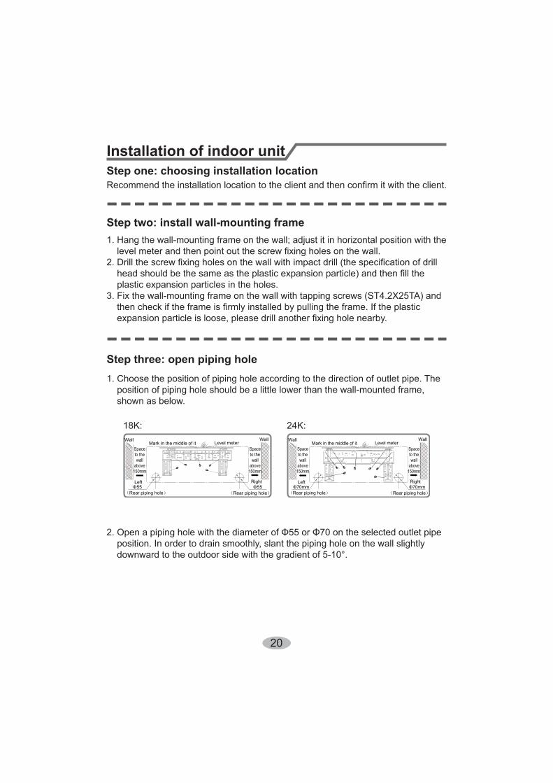
1. Choose the position of piping hole according to the direction of outlet pipe. The position of piping hole should be a little lower than the wall-mounted frame, shown as below.
Step three: open piping hole
y
18K: 24K:
Left
Wall
Φ55Right
Mark in the middle of it Level meter
Rear piping hole
Wall
Spaceto thewall
above150mm
Spaceto thewall
above150mm
Φ55Rear piping hole
Left
Wall
Φ70mmRight
Mark in the middle of it Level meter
Rear piping hole
Wall
Spaceto thewall
above150mm
Spaceto thewall
above150mm
Φ70mmRear piping hole
21
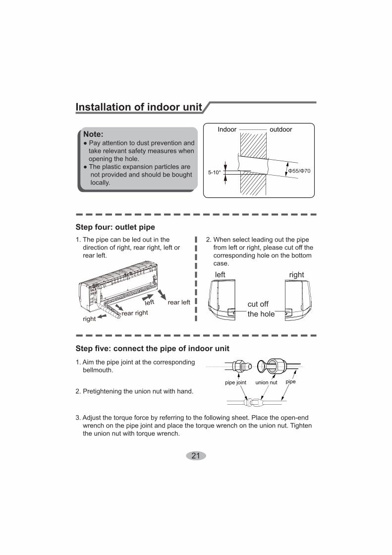
bellmouth.
2. Pretightening the union nut with hand.
wrench on the pipe joint and place the torque wrench on the union nut. Tighten the union nut with torque wrench.
2. When select leading out the pipe from left or right, please cut off the corresponding hole on the bottom case.
cut offthe hole
left right
1. The pipe can be led out in the direction of right, rear right, left or rear left.
left rear left
rightrear right
Step four: outlet pipe
Installation of indoor unit
Indoor
5-10°
outdoorNote:
union nutpipe joint pipe
22
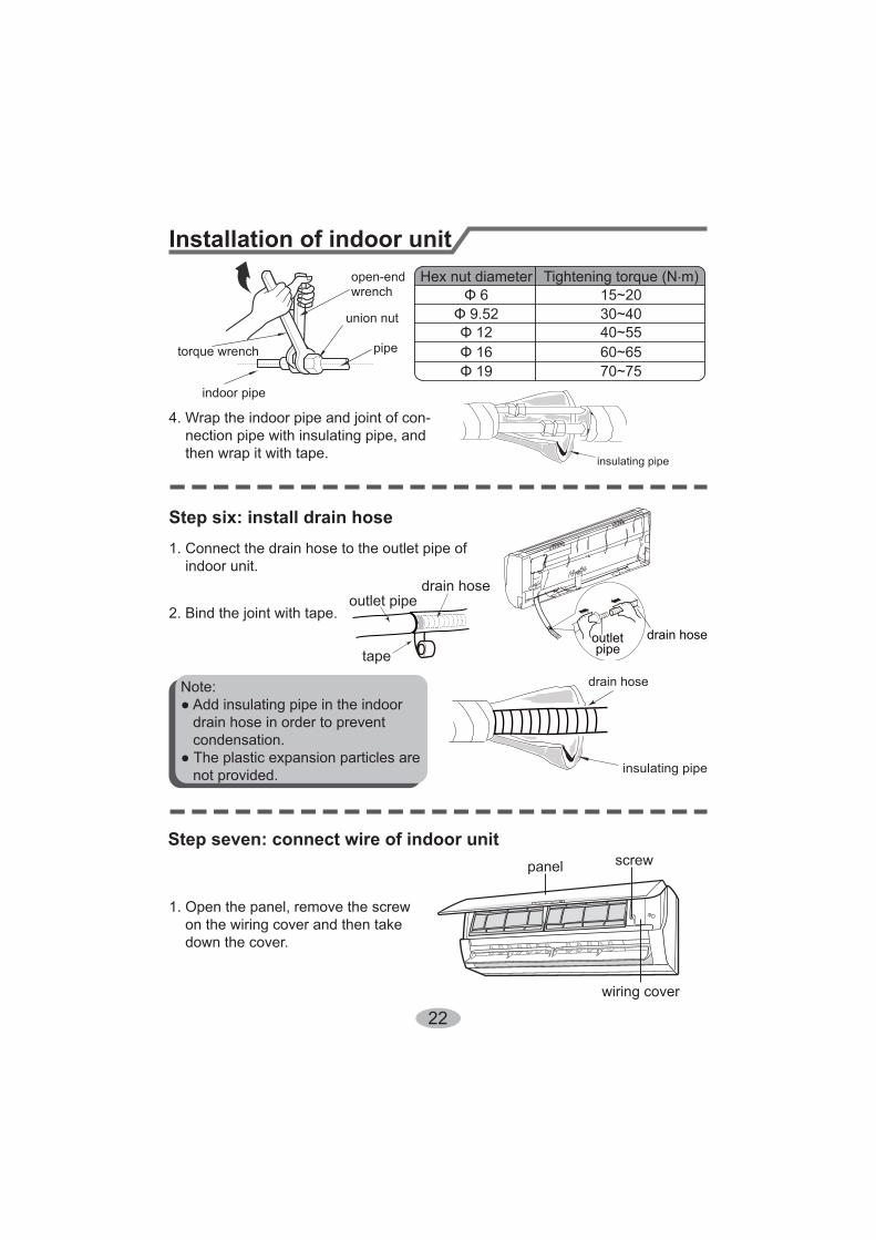
4. Wrap the indoor pipe and joint of con- nection pipe with insulating pipe, and then wrap it with tape.
Step six: install drain hose
Installation of indoor unit
torque wrench
open-endwrench
indoor pipe
pipe
union nut
Hex nut diameter Tightening torque (N.m)
30~4040~5560~6570~75
15~20
insulating pipe
1. Connect the drain hose to the outlet pipe of indoor unit.
2. Bind the joint with tape.outletpipe
drain hose
drain hose
tape
outlet pipe
drain hose
insulating pipe
Note:
drain hose in order to prevent condensation.
not provided.
1. Open the panel, remove the screw on the wiring cover and then take down the cover.
wiring cover
screwpanel
Step seven: connect wire of indoor unit

23
4.Put wiring cover back and then tighten the screw.5.Close the panel.
Installation of indoor unit
Note:
installation.
The circuit break should be all-pole parting and the contact parting distance should be more than 3mm.
3. Remove the wire clip; connect the power connection wire to the wiring terminal
with wire clip.
N(1) 2 3
blue black brown yellow-green
Outdoor unit connection
18、24K Heat pump type:
power connectionwire
cable-crosshole
2. Make the power connection wire go through the cable-cross hole at the back of indoor unit and then pull it out from the front side.

24
Installation of indoor unitStep eight: bind up pipe1. Bind up the connection pipe, power cord and drain hose with the band.
indoor unit gaspipe
indoor andoutdoor power cord
liquid pipe
drain hoseband
2. Reserve a certain length of drain hose and power cord for installation when binding them. When binding to a certain degree, separate the indoor power and then separate the drain hose.
3. Bind them evenly.4. The liquid pipe and gas pipe should be bound separately at the end.
Note:
at the bottom.
drain hose bandconnection pipe
indoor power cord
Step nine: hang the indoor unit1. Put the bound pipes in the wall pipe and then make them pass through the wall hole.2. Hang the indoor unit on the wall-mounting frame.3. Stuff the gap between pipes and wall hole with sealing gum.4. Fix the wall pipe.
Note:
indoor outdoor
wall pipesealing gum
upper hook
lower hook ofwall-mounting frame
25
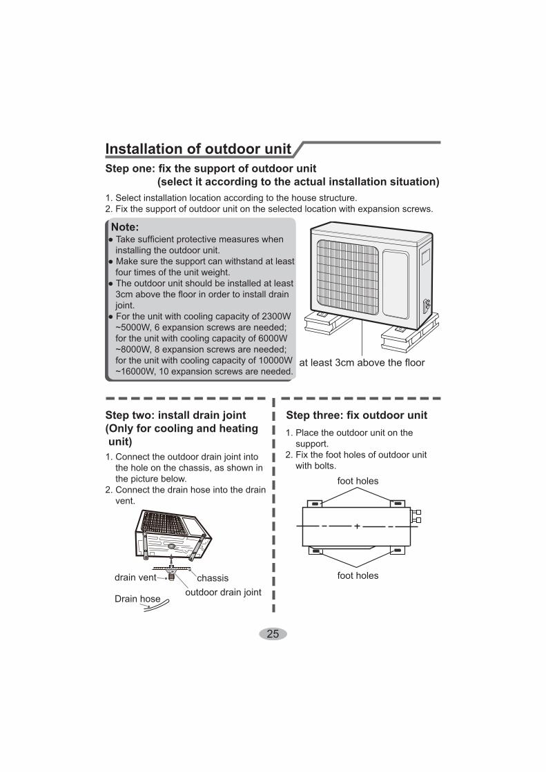
Installation of outdoor unit
(select it according to the actual installation situation)1. Select installation location according to the house structure.2. Fix the support of outdoor unit on the selected location with expansion screws.
at least 3cm above the floor
Note:
installing the outdoor unit.Make sure the support can withstand at least
four times of the unit weight.
joint.
~5000W, 6 expansion screws are needed; for the unit with cooling capacity of 6000W ~8000W, 8 expansion screws are needed; for the unit with cooling capacity of 10000W
~16000W, 10 expansion screws are needed.
Step two: install drain joint(Only for cooling and heating unit)1. Connect the outdoor drain joint into the hole on the chassis, as shown in the picture below.2. Connect the drain hose into the drain vent.
chassisoutdoor drain joint
Drain hose
drain vent
1. Place the outdoor unit on the support.2. Fix the foot holes of outdoor unit with bolts.
foot holes
foot holes
26
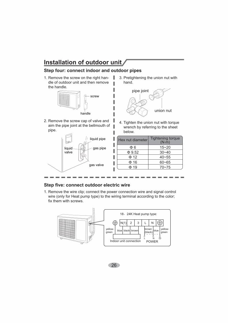
Installation of outdoor unitStep four: connect indoor and outdoor pipes1. Remove the screw on the right han- dle of outdoor unit and then remove the handle.
2. Remove the screw cap of valve and aim the pipe joint at the bellmouth of pipe.
3. Pretightening the union nut with hand.
4. Tighten the union nut with torque wrench by referring to the sheet below.
handle
screw
gas pipe
liquid pipe
liquidvalve
gas valve
union nut
pipe joint
Hex nut diameter Tightening torque (N.m)
30~4040~5560~6570~75
15~20
1. Remove the wire clip; connect the power connection wire and signal control wire (only for Heat pump type) to the wiring terminal according to the color; fix them with screws.
Indoor unit connection POWER
N(1) 2 3 L
L
N
N
blue blueblack brown brown(black)
yellow-green
yellow-green
18、24K Heat pump type:
27
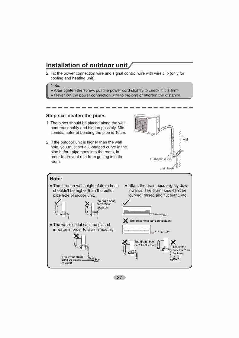
Step six: neaten the pipes1. The pipes should be placed along the wall, bent reasonably and hidden possibly. Min. semidiameter of bending the pipe is 10cm.
2. If the outdoor unit is higher than the wall
pipe before pipe goes into the room, in order to prevent rain from getting into the room.
pipe hole of indoor unit.
in water in order to drain smoothly.
Installation of outdoor unit
U-shaped curve
wall
drain hose
the drain hosecan't raiseupwards.
The drain hose can't be fluctuant
The drain hosecan't be fluctuant The water
outlet can't befluctuant
The water outlet can't be placedin water
Note:
2. Fix the power connection wire and signal control wire with wire clip (only for cooling and heating unit).
Note:

28
Vacuum pumping
Leakage detection
1. Remove the valve caps on the liquid valve and gas valve and the nut of refri- gerant charging vent.2. Connect the charging hose
gerant charging vent of gas valve and then connect the other charging hose to the vacuum pump.
pletely and operate for 10-15min to check if the
mains in -0.1MPa.4. Close the vacuum pump and maintain this status for 1-2min to check if the pres-
in -0.1MPa. If the pressure decreases, there may be leakage.
completely with inner hexagon spanner.6. Tighten the screw caps of valves and refrigerant charging vent.7. Reinstall the handle.
Use vacuum pump
liquid valve
gas valve
refrigerantcharging vent
nut of refrigerantcharging vent
vacuum pump
piezometer
valve cap
Lo Hi
inner hexagonspanner
openclose
1. With leakage detector: Check if there is leakage with leakage detector.2. With soap water: If leakage detector is not available, please use soap water for leakage detection.
29
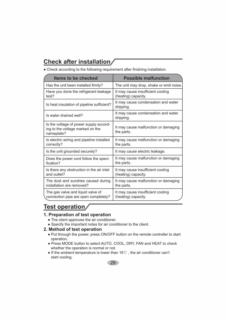
Check after installation
Test operation
Items to be checked Possible malfunctionThe unit may drop, shake or emit noise.
Have you done the refrigerant leakage test? (heating) capacity.
It may cause condensation and water dripping.
Is water drained well? It may cause condensation and water dripping.
Is the voltage of power supply accord-ing to the voltage marked on thenameplate?
It may cause malfunction or damaging the parts.
Is electric wiring and pipeline installedcorrectly?
It may cause malfunction or damaging the parts.
Is the unit grounded securely? It may cause electric leakage.
Does the power cord follow the speci- It may cause malfunction or damaging the parts.
Is there any obstruction in the air inlet and outlet? (heating) capacity.
The dust and sundries caused during installation are removed?
It may cause malfunction or damaging the parts.
The gas valve and liquid valve of connection pipe are open completely? (heating) capacity.
1. Preparation of test operation
2. Method of test operation
operation.
whether the operation is normal or not.
start cooling.

30
1. Standard length of connection pipe
4. The additional refrigerant oil and refrigerant charging required after prolonging connection pipe
standard length, you should add 5ml of refrigerant oil for each additional 5m of connection pipe.
of liquid pipe):
additional refrigerant charging amount per meter
the prolonged length of liquid pipe. The additional refrigerant charging amount per meter is different according to the diameter of liquid pipe. See the following sheet.
Coolingcapacity
Coolingcapacity
5000Btu/h(1465W)
24000Btu/h(7032W)
7000Btu/h(2051W)
28000Btu/h(8204W)
9000Btu/h(2637W)
36000Btu/h(10548W)
12000Btu/h(3516W)
42000Btu/h(12306W)
18000Btu/h(5274W)
48000Btu/h(14064W)
Max height difference
Max height difference
Max length of connec-tion pipe
Max length of connec-tion pipe
15 255 10
15 305 10
15 305 20
20 3010 20
25 3010 20
2.Min. length of connection pipe is 3m.
3.Max. length of connection pipe and max. high difference.
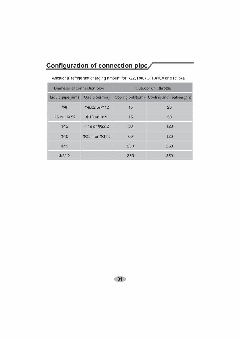
31
Diameter of connection pipe
Liquid pipe(mm) Gas pipe(mm)
_
_
Cooling only(g/m) Cooling and heating(g/m)
15
15
30
60
250 250
350350
120
120
50
20
Outdoor unit throttle
32
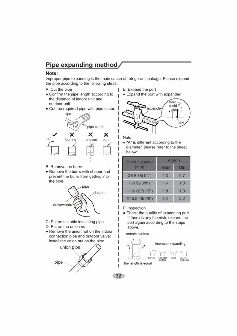
Pipe expanding methodNote:Improper pipe expanding is the main cause of refrigerant leakage. Please expandthe pipe according to the following steps:
the distance of indoor unit and outdoor unit.
pipe
pipe cutter
leaning uneven burr
B: Remove the burrs
prevent the burrs from getting into the pipe.
downwards
pipe
shaper
C: Put on suitable insulating pipeD: Put on the union nut
connection pipe and outdoor valve; install the union nut on the pipe.
union pipe
pipe
E: Expand the port
Note:
diameter, please refer to the sheet below:
expander
hardmold
pipe
F: Inspection
If there is any blemish, expand the port again according to the steps above.
the length is equal
improper expanding
leaning damagedsurface
crack uneventhickness
smooth surface
Outer diameter(mm) Max Min
1.3 0.7
1.6 1.0
1.8 1.0
2.4 2.2

66129914641


![DJ Controller DDJ-SB2...15 Check [DDJ-SB2] for the model to be used and then click the [Continue] icon and save the file. 16 Click the [Download Serato DJ Intro] icon. Unzip the downloaded](https://img.pdfslide.us/doc/110x75/5fa63eb76d08bc006c5b5c16/dj-controller-ddj-sb2-15-check-ddj-sb2-for-the-model-to-be-used-and-then-click.jpg)
![DJ Controller DDJ-SB2faq.pioneerdj.com/files/img/DRI1281A.pdf · DJ Controller DDJ-SB2 Operating Instructions ... [Pioneer_DJ_DDJ_SB2_Driver_x.xxx.exe] icon. 8 Proceed with installation](https://img.pdfslide.us/doc/110x75/5a7064ff7f8b9aac538be398/dj-controller-ddj-sb2faqpioneerdjcomfilesimgdri1281apdfpdf.jpg)