Embed Size (px)
Citation preview
Spectra 1728/EX & 1738/EX - 1 - Programming Guide
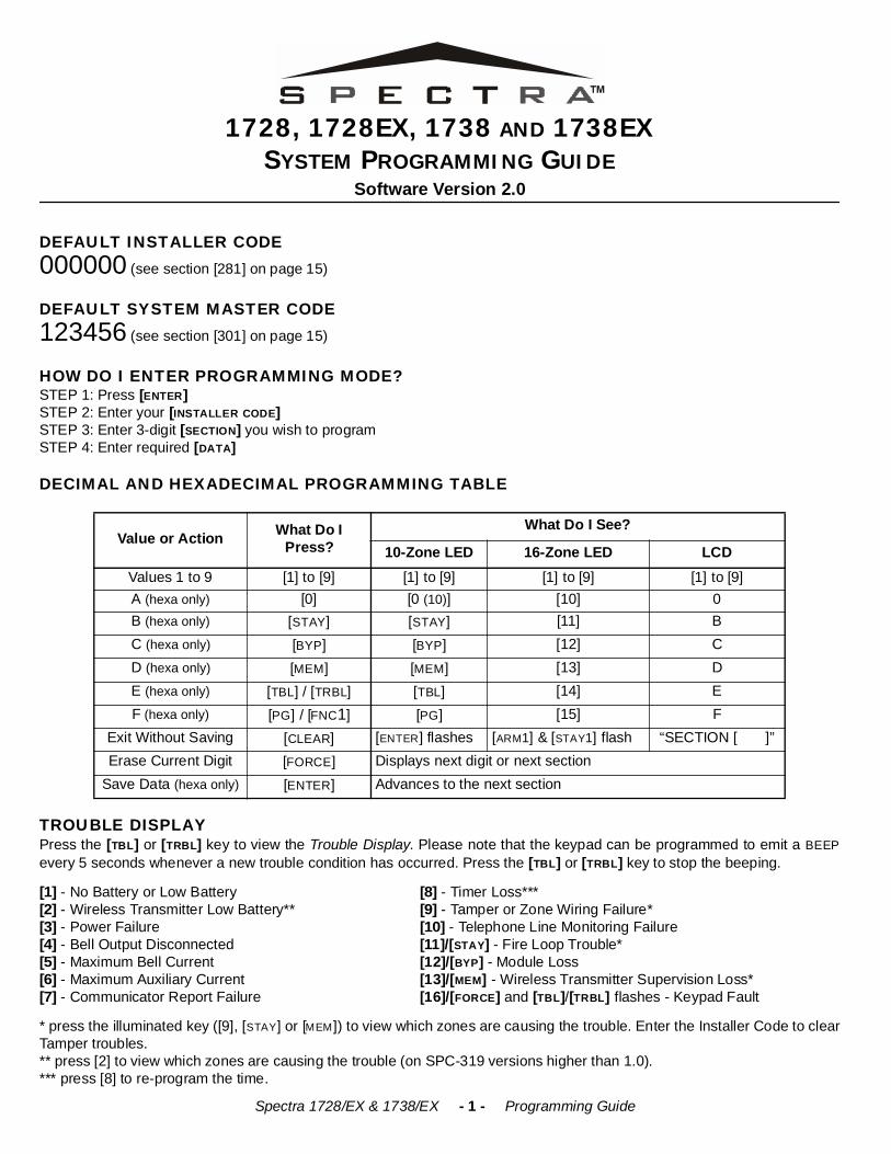
1728, 1728EX, 1738 AND 1738EXSYSTEM PROGRAMMING GUIDE
Software Version 2.0
DEFAULT INSTALLER CODE000000 (see section [281] on page 15)
DEFAULT SYSTEM MASTER CODE123456 (see section [301] on page 15)
HOW DO I ENTER PROGRAMMING MODE?STEP 1: Press [ENTER]STEP 2: Enter your [INSTALLER CODE] STEP 3: Enter 3-digit [SECTION] you wish to programSTEP 4: Enter required [DATA]
DECIMAL AND HEXADECIMAL PROGRAMMING TABLE
TROUBLE DISPLAYPress the [TBL] or [TRBL] key to view the Trouble Display. Please note that the keypad can be programmed to emit a BEEPevery 5 seconds whenever a new trouble condition has occurred. Press the [TBL] or [TRBL] key to stop the beeping.
[1] - No Battery or Low Battery [8] - Timer Loss***[2] - Wireless Transmitter Low Battery** [9] - Tamper or Zone Wiring Failure*[3] - Power Failure [10] - Telephone Line Monitoring Failure[4] - Bell Output Disconnected [11]/[STAY] - Fire Loop Trouble*[5] - Maximum Bell Current [12]/[BYP] - Module Loss[6] - Maximum Auxiliary Current [13]/[MEM] - Wireless Transmitter Supervision Loss*[7] - Communicator Report Failure [16]/[FORCE] and [TBL]/[TRBL] flashes - Keypad Fault
* press the illuminated key ([9], [STAY] or [MEM]) to view which zones are causing the trouble. Enter the Installer Code to clearTamper troubles.** press [2] to view which zones are causing the trouble (on SPC-319 versions higher than 1.0).*** press [8] to re-program the time.
Value or Action What Do I Press?
What Do I See?
10-Zone LED 16-Zone LED LCDValues 1 to 9 [1] to [9] [1] to [9] [1] to [9] [1] to [9]A (hexa only) [0] [0 (10)] [10] 0B (hexa only) [STAY] [STAY] [11] BC (hexa only) [BYP] [BYP] [12] CD (hexa only) [MEM] [MEM] [13] DE (hexa only) [TBL] / [TRBL] [TBL] [14] EF (hexa only) [PG] / [FNC1] [PG] [15] F
Exit Without Saving [CLEAR] [ENTER] flashes [ARM1] & [STAY1] flash “SECTION [ ]”Erase Current Digit [FORCE] Displays next digit or next section
Save Data (hexa only) [ENTER] Advances to the next section
Spectra 1728/EX & 1738/EX - 2 - Programming Guide
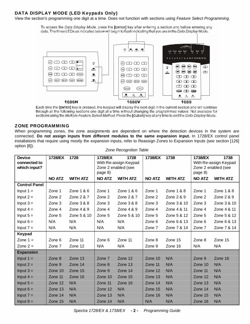
DATA DISPLAY MODE (LED Keypads Only)View the section’s programming one digit at a time. Does not function with sections using Feature Select Programming.
ZONE PROGRAMMINGWhen programming zones, the zone assignments are dependent on where the detection devices in the system areconnected. Do not assign inputs from different modules to the same expansion input. In 1728/EX control panelinstallations that require using mostly the expansion inputs, refer to Reassign Zones to Expansion Inputs (see section [126]option [8]).
Zone Recognition Table
Device connected to which input?
1728/EX 1728 1728/EX 1728With Re-assign Keypad Zone 2 enabled (see page 8)
1738/EX 1738 1738/EX 1738With Re-assign Keypad Zone 2 enabled (see page 8)
NO ATZ WITH ATZ NO ATZ WITH ATZ NO ATZ WITH ATZ NO ATZ WITH ATZControl PanelInput 1 = Zone 1 Zone 1 & 6 Zone 1 Zone 1 & 6 Zone 1 Zone 1 & 8 Zone 1 Zone 1 & 8Input 2 = Zone 2 Zone 2 & 7 Zone 2 Zone 2 & 7 Zone 2 Zone 2 & 9 Zone 2 Zone 2 & 9Input 3 = Zone 3 Zone 3 & 8 Zone 3 Zone 3 & 8 Zone 3 Zone 3 & 10 Zone 3 Zone 3 & 10Input 4 = Zone 4 Zone 4 & 9 Zone 4 Zone 4 & 9 Zone 4 Zone 4 & 11 Zone 4 Zone 4 & 11Input 5 = Zone 5 Zone 5 & 10 Zone 5 Zone 5 & 10 Zone 5 Zone 5 & 12 Zone 5 Zone 5 & 12Input 6 = N/A N/A N/A N/A Zone 6 Zone 6 & 13 Zone 6 Zone 6 & 13Input 7 = N/A N/A N/A N/A Zone 7 Zone 7 & 14 Zone 7 Zone 7 & 14KeypadZone 1 = Zone 6 Zone 11 Zone 6 Zone 11 Zone 8 Zone 15 Zone 8 Zone 15Zone 2 = Zone 7 Zone 12 N/A N/A Zone 9 Zone 16 N/A N/AExpansionInput 1 = Zone 8 Zone 13 Zone 7 Zone 12 Zone 10 N/A Zone 9 Zone 16Input 2 = Zone 9 Zone 14 Zone 8 Zone 13 Zone 11 N/A Zone 10 N/AInput 3 = Zone 10 Zone 15 Zone 9 Zone 14 Zone 12 N/A Zone 11 N/AInput 4 = Zone 11 Zone 16 Zone 10 Zone 15 Zone 13 N/A Zone 12 N/AInput 5 = Zone 12 N/A Zone 11 Zone 16 Zone 14 N/A Zone 13 N/AInput 6 = Zone 13 N/A Zone 12 N/A Zone 15 N/A Zone 14 N/AInput 7 = Zone 14 N/A Zone 13 N/A Zone 16 N/A Zone 15 N/AInput 8 = Zone 15 N/A Zone 14 N/A N/A N/A Zone 16 N/A
Spectra 1728/EX & 1738/EX - 3 - Programming Guide
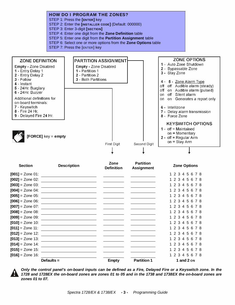
Only the control panel’s on-board inputs can be defined as a Fire, Delayed Fire or a Keyswitch zone. In the1728 and 1728EX the on-board zones are zones 01 to 05 and in the 1738 and 1738EX the on-board zones arezones 01 to 07.
HOW DO I PROGRAM THE ZONES?STEP 1: Press the [ENTER] keySTEP 2: Enter the [INSTALLER CODE] (Default: 000000)STEP 3: Enter 3-digit [SECTION]STEP 4: Enter one digit from the Zone Definition tableSTEP 5: Enter one digit from the Partition Assignment tableSTEP 6: Select one or more options from the Zone Options tableSTEP 7: Press the [ENTER] key
Section Description ZoneDefinition
PartitionAssignment Zone Options
[001] = Zone 01: 1 2 3 4 5 6 7 8[002] = Zone 02: 1 2 3 4 5 6 7 8[003] = Zone 03: 1 2 3 4 5 6 7 8[004] = Zone 04: 1 2 3 4 5 6 7 8[005] = Zone 05: 1 2 3 4 5 6 7 8[006] = Zone 06: 1 2 3 4 5 6 7 8[007] = Zone 07: 1 2 3 4 5 6 7 8[008] = Zone 08: 1 2 3 4 5 6 7 8[009] = Zone 09: 1 2 3 4 5 6 7 8[010] = Zone 10: 1 2 3 4 5 6 7 8[011] = Zone 11: 1 2 3 4 5 6 7 8[012] = Zone 12: 1 2 3 4 5 6 7 8[013] = Zone 13: 1 2 3 4 5 6 7 8[014] = Zone 14: 1 2 3 4 5 6 7 8[015] = Zone 15: 1 2 3 4 5 6 7 8[016] = Zone 16: 1 2 3 4 5 6 7 8
Defaults = Empty Partition 1 1 and 2 ON
[FORCE] key = empty
Spectra 1728/EX & 1738/EX - 4 - Programming Guide
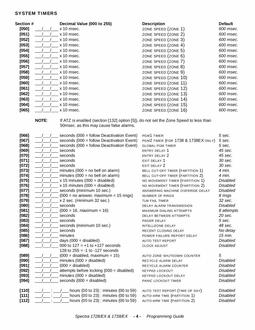
SYSTEM TIMERS
Section # Decimal Value (000 to 255) Description Default[050] ___/___/___ x 10 msec. ZONE SPEED (ZONE 1) 600 msec.[051] ___/___/___ x 10 msec. ZONE SPEED (ZONE 2) 600 msec.[052] ___/___/___ x 10 msec. ZONE SPEED (ZONE 3) 600 msec.[053] ___/___/___ x 10 msec. ZONE SPEED (ZONE 4) 600 msec.[054] ___/___/___ x 10 msec. ZONE SPEED (ZONE 5) 600 msec.[055] ___/___/___ x 10 msec. ZONE SPEED (ZONE 6) 600 msec.[056] ___/___/___ x 10 msec. ZONE SPEED (ZONE 7) 600 msec.[057] ___/___/___ x 10 msec. ZONE SPEED (ZONE 8) 600 msec.[058] ___/___/___ x 10 msec. ZONE SPEED (ZONE 9) 600 msec.[059] ___/___/___ x 10 msec. ZONE SPEED (ZONE 10) 600 msec.[060] ___/___/___ x 10 msec. ZONE SPEED (ZONE 11) 600 msec.[061] ___/___/___ x 10 msec. ZONE SPEED (ZONE 12) 600 msec.[062] ___/___/___ x 10 msec. ZONE SPEED (ZONE 13) 600 msec.[063] ___/___/___ x 10 msec. ZONE SPEED (ZONE 14) 600 msec.[064] ___/___/___ x 10 msec. ZONE SPEED (ZONE 15) 600 msec.[065] ___/___/___ x 10 msec. ZONE SPEED (ZONE 16) 600 msec.
NOTE: If ATZ is enabled (section [132] option [5]), do not set the Zone Speed to less than 50msec. as this may cause false alarms.
[066] ___/___/___ seconds (000 = follow Deactivation Event) PGM1 TIMER 5 sec.[067] ___/___/___ seconds (000 = follow Deactivation Event) PGM2 TIMER (FOR 1738 & 1738EX ONLY) 5 sec.[068] ___/___/___ seconds (000 = follow Deactivation Event) GLOBAL PGM TIMER 5 sec.[069] ___/___/___ seconds ENTRY DELAY 1 45 sec.[070] ___/___/___ seconds ENTRY DELAY 2 45 sec.[071] ___/___/___ seconds EXIT DELAY 1 30 sec.[072] ___/___/___ seconds EXIT DELAY 2 30 sec.[073] ___/___/___ minutes (000 = no bell on alarm) BELL CUT-OFF TIMER (PARTITION 1) 4 min.[074] ___/___/___ minutes (000 = no bell on alarm) BELL CUT-OFF TIMER (PARTITION 2) 4 min.[075] ___/___/___ x 15 minutes (000 = disabled) NO MOVEMENT TIMER (PARTITION 1) Disabled[076] ___/___/___ x 15 minutes (000 = disabled) NO MOVEMENT TIMER (PARTITION 2) Disabled[077] ___/___/___ seconds (minimum 10 sec.) ANSWERING MACHINE OVERRIDE DELAY Disabled[078] ___/___/___ (000 = no answer, maximum = 15 rings) NUMBER OF RINGS 8 rings[079] ___/___/___ x 2 sec. (minimum 32 sec.) TLM FAIL TIMER 32 sec.[080] ___/___/___ seconds DELAY ALARM TRANSMISSION Disabled[081] ___/___/___ (000 = 16, maximum = 16) MAXIMUM DIALING ATTEMPTS 8 attempts[082] ___/___/___ seconds DELAY BETWEEN ATTEMPTS 20 sec.[083] ___/___/___ seconds PAGER DELAY 5 sec.[084] ___/___/___ seconds (minimum 10 sec.) INTELLIZONE DELAY 48 sec.[085] ___/___/___ seconds RECENT CLOSING DELAY No delay[086] ___/___/___ minutes POWER FAILURE REPORT DELAY 15 min.[087] ___/___/___ days (000 = disabled) AUTO TEST REPORT Disabled[088] ___/___/___ 000 to 127 = +1 to +127 seconds
128 to 255 = -1 to -127 secondsCLOCK ADJUST Disabled
[089] ___/___/___ (000 = disabled, maximum = 15) AUTO ZONE SHUTDOWN COUNTER 5[090] ___/___/___ minutes (000 = disabled) RECYCLE ALARM DELAY Disabled[091] ___/___/___ (000 = disabled) RECYCLE ALARM COUNTER Disabled[092] ___/___/___ attempts before locking (000 = disabled) KEYPAD LOCKOUT Disabled[093] ___/___/___ minutes (000 = disabled) KEYPAD LOCKOUT DELAY Disabled[094] ___/___/___ seconds (000 = disabled) PANIC LOCKOUT TIMER Disabled
[110] ___/___ : ___/___ hours (00 to 23) : minutes (00 to 59) ___/___ : ___/___ hours (00 to 23) : minutes (00 to 59) ___/___ : ___/___ hours (00 to 23) : minutes (00 to 59)
AUTO TEST REPORT (TIME OF DAY) Disabled[111] AUTO-ARM TIME (PARTITION 1) Disabled[112] AUTO-ARM TIME (PARTITION 2) Disabled
Spectra 1728/EX & 1738/EX - 5 - Programming Guide
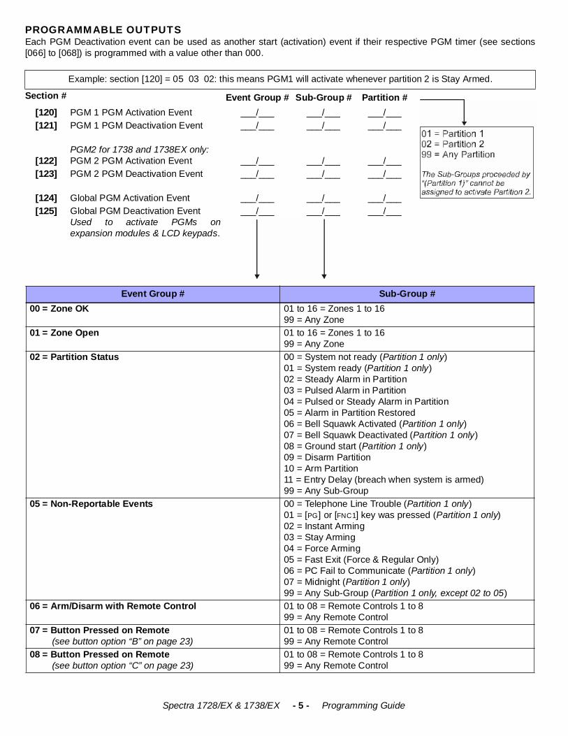
PROGRAMMABLE OUTPUTSEach PGM Deactivation event can be used as another start (activation) event if their respective PGM timer (see sections[066] to [068]) is programmed with a value other than 000.
Example: section [120] = 05 03 02: this means PGM1 will activate whenever partition 2 is Stay Armed.
Section # Event Group # Sub-Group # Partition #[120] PGM 1 PGM Activation Event ___/___ ___/___ ___/___[121] PGM 1 PGM Deactivation Event ___/___ ___/___ ___/___
[122]PGM2 for 1738 and 1738EX only:PGM 2 PGM Activation Event ___/___ ___/___ ___/___
[123] PGM 2 PGM Deactivation Event ___/___ ___/___ ___/___
[124] Global PGM Activation Event ___/___ ___/___ ___/___[125] Global PGM Deactivation Event
Used to activate PGMs onexpansion modules & LCD keypads.
___/___ ___/___ ___/___
Event Group # Sub-Group #00 = Zone OK 01 to 16 = Zones 1 to 16
99 = Any Zone01 = Zone Open 01 to 16 = Zones 1 to 16
99 = Any Zone02 = Partition Status 00 = System not ready (Partition 1 only)
01 = System ready (Partition 1 only)02 = Steady Alarm in Partition03 = Pulsed Alarm in Partition04 = Pulsed or Steady Alarm in Partition05 = Alarm in Partition Restored06 = Bell Squawk Activated (Partition 1 only)07 = Bell Squawk Deactivated (Partition 1 only)08 = Ground start (Partition 1 only)09 = Disarm Partition10 = Arm Partition11 = Entry Delay (breach when system is armed)99 = Any Sub-Group
05 = Non-Reportable Events 00 = Telephone Line Trouble (Partition 1 only)01 = [PG] or [FNC1] key was pressed (Partition 1 only)02 = Instant Arming03 = Stay Arming 04 = Force Arming05 = Fast Exit (Force & Regular Only)06 = PC Fail to Communicate (Partition 1 only)07 = Midnight (Partition 1 only)99 = Any Sub-Group (Partition 1 only, except 02 to 05)
06 = Arm/Disarm with Remote Control 01 to 08 = Remote Controls 1 to 899 = Any Remote Control
07 = Button Pressed on Remote (see button option “B” on page 23)
01 to 08 = Remote Controls 1 to 899 = Any Remote Control
08 = Button Pressed on Remote (see button option “C” on page 23)
01 to 08 = Remote Controls 1 to 899 = Any Remote Control
Spectra 1728/EX & 1738/EX - 6 - Programming Guide
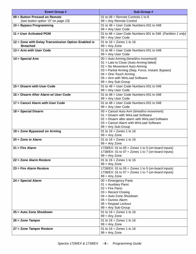
09 = Button Pressed on Remote (see button option “D” on page 23)
01 to 08 = Remote Controls 1 to 899 = Any Remote Control
10 = Bypass Programming 01 to 48 = User Code Numbers 001 to 04899 = Any User Code
11 = User Activated PGM 01 to 48 = User Code Numbers 001 to 048 (Partition 1 only)99 = Any User Code
12 = Zone with Delay Transmission Option Enabled is Breached
01 to 16 = Zones 1 to 1699 = Any Zone
13 = Arm with User Code 01 to 48 = User Code Numbers 001 to 04899 = Any User Code
14 = Special Arm 00 = Auto Arming (timed/no movement)01 = Late to Close (Auto-Arming failed)02 = No Movement Auto-Arming 03 = Partial Arming (Stay, Force, Instant, Bypass)04 = One-Touch Arming05 = Arm with WinLoad Software99 = Any Sub-Group
15 = Disarm with User Code 01 to 48 = User Code Numbers 001 to 04899 = Any User Code
16 = Disarm After Alarm w/ User Code 01 to 48 = User Code Numbers 001 to 04899 = Any User Code
17 = Cancel Alarm with User Code 01 to 48 = User Code Numbers 001 to 04899 = Any User Code
18 = Special Disarm 00 = Cancel Auto Arm (timed/no movement)01 = Disarm with WinLoad Software02 = Disarm after alarm with WinLoad Software03 = Cancel Alarm with WinLoad Software99 = Any Sub-Group
19 = Zone Bypassed on Arming 01 to 16 = Zones 1 to 1699 = Any Zone
20 = Zone in Alarm 01 to 16 = Zones 1 to 1699 = Any Zone
21 = Fire Alarm 1728/EX: 01 to 05 = Zones 1 to 5 (on-board inputs)1738/EX: 01 to 07 = Zones 1 to 7 (on-board inputs)99 = Any Zone
22 = Zone Alarm Restore 01 to 16 = Zones 1 to 1699 = Any Zone
23 = Fire Alarm Restore 1728/EX: 01 to 05 = Zones 1 to 5 (on-board inputs)1738/EX: 01 to 07 = Zones 1 to 7 (on-board inputs)99 = Any Zone
24 = Special Alarm 00 = Emergency Panic01 = Auxiliary Panic02 = Fire Panic 03 = Recent Closing04 = Auto Zone Shutdown05 = Duress Alarm06 = Keypad Lockout99 = Any Sub-Group
25 = Auto Zone Shutdown 01 to 16 = Zones 1 to 1699 = Any Zone
26 = Zone Tamper 01 to 16 = Zones 1 to 1699 = Any Zone
27 = Zone Tamper Restore 01 to 16 = Zones 1 to 1699 = Any Zone
Event Group # Sub-Group #
Spectra 1728/EX & 1738/EX - 7 - Programming Guide
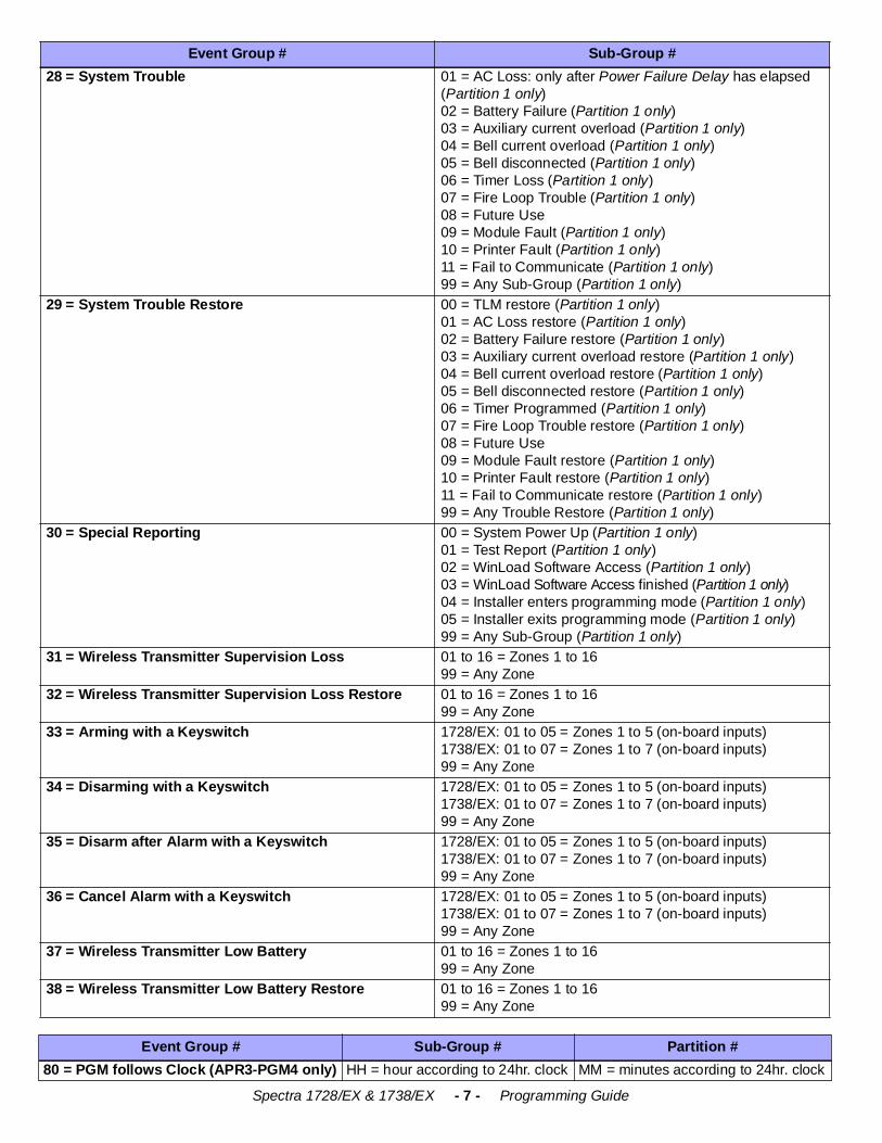
28 = System Trouble 01 = AC Loss: only after Power Failure Delay has elapsed (Partition 1 only)02 = Battery Failure (Partition 1 only)03 = Auxiliary current overload (Partition 1 only)04 = Bell current overload (Partition 1 only)05 = Bell disconnected (Partition 1 only)06 = Timer Loss (Partition 1 only)07 = Fire Loop Trouble (Partition 1 only)08 = Future Use09 = Module Fault (Partition 1 only)10 = Printer Fault (Partition 1 only)11 = Fail to Communicate (Partition 1 only)99 = Any Sub-Group (Partition 1 only)
29 = System Trouble Restore 00 = TLM restore (Partition 1 only)01 = AC Loss restore (Partition 1 only)02 = Battery Failure restore (Partition 1 only)03 = Auxiliary current overload restore (Partition 1 only)04 = Bell current overload restore (Partition 1 only)05 = Bell disconnected restore (Partition 1 only)06 = Timer Programmed (Partition 1 only)07 = Fire Loop Trouble restore (Partition 1 only)08 = Future Use09 = Module Fault restore (Partition 1 only)10 = Printer Fault restore (Partition 1 only)11 = Fail to Communicate restore (Partition 1 only)99 = Any Trouble Restore (Partition 1 only)
30 = Special Reporting 00 = System Power Up (Partition 1 only)01 = Test Report (Partition 1 only)02 = WinLoad Software Access (Partition 1 only)03 = WinLoad Software Access finished (Partition 1 only)04 = Installer enters programming mode (Partition 1 only)05 = Installer exits programming mode (Partition 1 only)99 = Any Sub-Group (Partition 1 only)
31 = Wireless Transmitter Supervision Loss 01 to 16 = Zones 1 to 1699 = Any Zone
32 = Wireless Transmitter Supervision Loss Restore 01 to 16 = Zones 1 to 1699 = Any Zone
33 = Arming with a Keyswitch 1728/EX: 01 to 05 = Zones 1 to 5 (on-board inputs)1738/EX: 01 to 07 = Zones 1 to 7 (on-board inputs)99 = Any Zone
34 = Disarming with a Keyswitch 1728/EX: 01 to 05 = Zones 1 to 5 (on-board inputs)1738/EX: 01 to 07 = Zones 1 to 7 (on-board inputs)99 = Any Zone
35 = Disarm after Alarm with a Keyswitch 1728/EX: 01 to 05 = Zones 1 to 5 (on-board inputs)1738/EX: 01 to 07 = Zones 1 to 7 (on-board inputs)99 = Any Zone
36 = Cancel Alarm with a Keyswitch 1728/EX: 01 to 05 = Zones 1 to 5 (on-board inputs)1738/EX: 01 to 07 = Zones 1 to 7 (on-board inputs)99 = Any Zone
37 = Wireless Transmitter Low Battery 01 to 16 = Zones 1 to 1699 = Any Zone
38 = Wireless Transmitter Low Battery Restore 01 to 16 = Zones 1 to 1699 = Any Zone
Event Group # Sub-Group # Partition #80 = PGM follows Clock (APR3-PGM4 only) HH = hour according to 24hr. clock MM = minutes according to 24hr. clock
Event Group # Sub-Group #
Spectra 1728/EX & 1738/EX - 8 - Programming Guide
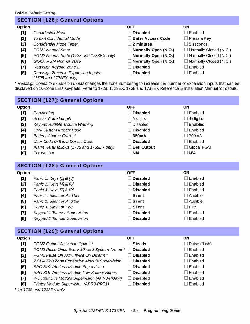
Bold = Default Setting
* Reassign Zones to Expansion Inputs changes the zone numbering to increase the number of expansion inputs that can bedisplayed on 10-Zone LED Keypads. Refer to 1728, 1728EX, 1738 and 1738EX Reference & Installation Manual for details.
* for 1738 and 1738EX only
SECTION [126]: General OptionsOption OFF ON
[1] Confidential Mode ! Disabled ! Enabled[2] To Exit Confidential Mode ! Enter Access Code ! Press a Key[3] Confidential Mode Timer ! 2 minutes ! 5 seconds[4] PGM1 Normal State ! Normally Open (N.O.) ! Normally Closed (N.C.)[5] PGM2 Normal State (1738 and 1738EX only) ! Normally Open (N.O.) ! Normally Closed (N.C.)[6] Global PGM Normal State ! Normally Open (N.O.) ! Normally Closed (N.C.)[7] Reassign Keypad Zone 2 ! Disabled ! Enabled[8] Reassign Zones to Expansion Inputs*
(1728 and 1728EX only) ! Disabled ! Enabled
SECTION [127]: General OptionsOption OFF ON
[1] Partitioning ! Disabled ! Enabled[2] Access Code Length ! 6-digits ! 4-digits[3] Keypad Audible Trouble Warning ! Disabled ! Enabled[4] Lock System Master Code ! Disabled ! Enabled[5] Battery Charge Current ! 350mA ! 700mA[6] User Code 048 is a Duress Code ! Disabled ! Enabled[7] Alarm Relay follows (1738 and 1738EX only) ! Bell Output ! Global PGM[8] Future Use ! N/A ! N/A
SECTION [128]: General Options Option OFF ON
[1] Panic 1: Keys [1] & [3] ! Disabled ! Enabled [2] Panic 2: Keys [4] & [6] ! Disabled ! Enabled [3] Panic 3: Keys [7] & [9] ! Disabled ! Enabled[4] Panic 1: Silent or Audible ! Silent ! Audible[5] Panic 2: Silent or Audible ! Silent ! Audible[6] Panic 3: Silent or Fire ! Silent ! Fire[7] Keypad 1 Tamper Supervision ! Disabled ! Enabled [8] Keypad 2 Tamper Supervision ! Disabled ! Enabled
SECTION [129]: General OptionsOption OFF ON
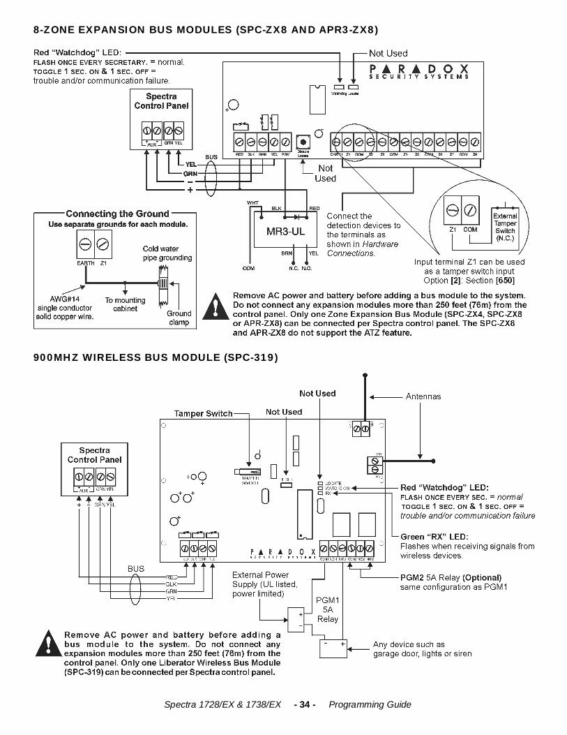
[1] PGM2 Output Activation Option * ! Steady ! Pulse (flash)[2] PGM2 Pulse Once Every 30sec if System Armed * ! Disabled ! Enabled [3] PGM2 Pulse On Arm, Twice On Disarm * ! Disabled ! Enabled [4] ZX4 & ZX8 Zone Expansion Module Supervision ! Disabled ! Enabled [5] SPC-319 Wireless Module Supervision ! Disabled ! Enabled [6] SPC-319 Wireless Module Low Battery Super. ! Disabled ! Enabled [7] 4-Output Bus Module Supervision (APR3-PGM4) ! Disabled ! Enabled[8] Printer Module Supervision (APR3-PRT1) ! Disabled ! Enabled
Spectra 1728/EX & 1738/EX - 9 - Programming Guide
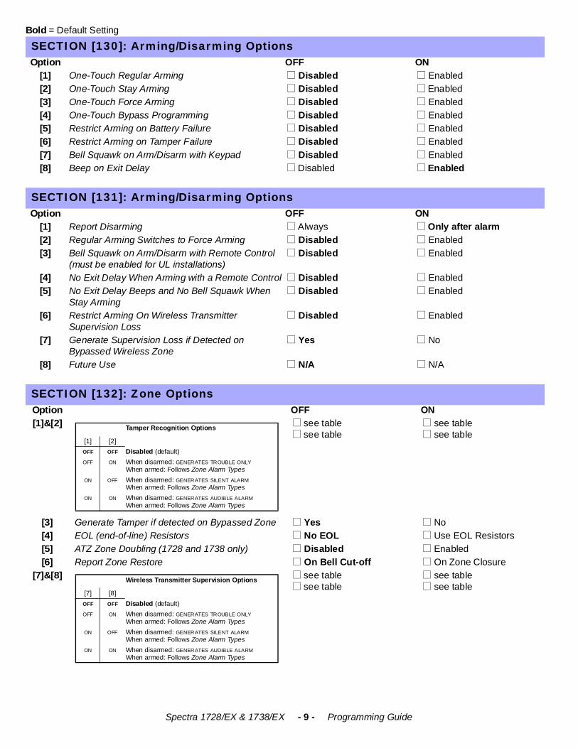
Bold = Default Setting
SECTION [130]: Arming/Disarming OptionsOption OFF ON
[1] One-Touch Regular Arming ! Disabled ! Enabled [2] One-Touch Stay Arming ! Disabled ! Enabled [3] One-Touch Force Arming ! Disabled ! Enabled[4] One-Touch Bypass Programming ! Disabled ! Enabled[5] Restrict Arming on Battery Failure ! Disabled ! Enabled[6] Restrict Arming on Tamper Failure ! Disabled ! Enabled[7] Bell Squawk on Arm/Disarm with Keypad ! Disabled ! Enabled[8] Beep on Exit Delay ! Disabled ! Enabled
SECTION [131]: Arming/Disarming OptionsOption OFF ON
[1] Report Disarming ! Always ! Only after alarm[2] Regular Arming Switches to Force Arming ! Disabled ! Enabled[3] Bell Squawk on Arm/Disarm with Remote Control
(must be enabled for UL installations) ! Disabled ! Enabled
[4] No Exit Delay When Arming with a Remote Control ! Disabled ! Enabled[5] No Exit Delay Beeps and No Bell Squawk When
Stay Arming ! Disabled ! Enabled
[6] Restrict Arming On Wireless Transmitter Supervision Loss
! Disabled ! Enabled
[7] Generate Supervision Loss if Detected on Bypassed Wireless Zone
! Yes ! No
[8] Future Use ! N/A ! N/A
SECTION [132]: Zone OptionsOption OFF ON[1]&[2] ! see table
! see table ! see table ! see table
[3] Generate Tamper if detected on Bypassed Zone ! Yes ! No[4] EOL (end-of-line) Resistors ! No EOL ! Use EOL Resistors [5] ATZ Zone Doubling (1728 and 1738 only) ! Disabled ! Enabled[6] Report Zone Restore ! On Bell Cut-off ! On Zone Closure
[7]&[8] ! see table ! see table
! see table ! see table
Tamper Recognition Options
[1] [2]OFF OFF Disabled (default)OFF ON When disarmed: GENERATES TROUBLE ONLY
When armed: Follows Zone Alarm Types ON OFF When disarmed: GENERATES SILENT ALARM
When armed: Follows Zone Alarm TypesON ON When disarmed: GENERATES AUDIBLE ALARM
When armed: Follows Zone Alarm Types
Wireless Transmitter Supervision Options
[7] [8]OFF OFF Disabled (default)OFF ON When disarmed: GENERATES TROUBLE ONLY
When armed: Follows Zone Alarm Types ON OFF When disarmed: GENERATES SILENT ALARM
When armed: Follows Zone Alarm TypesON ON When disarmed: GENERATES AUDIBLE ALARM
When armed: Follows Zone Alarm Types
Spectra 1728/EX & 1738/EX - 10 - Programming Guide
Bold = Default Setting
SECTION [133]: Partition 1 OptionsOption OFF ON
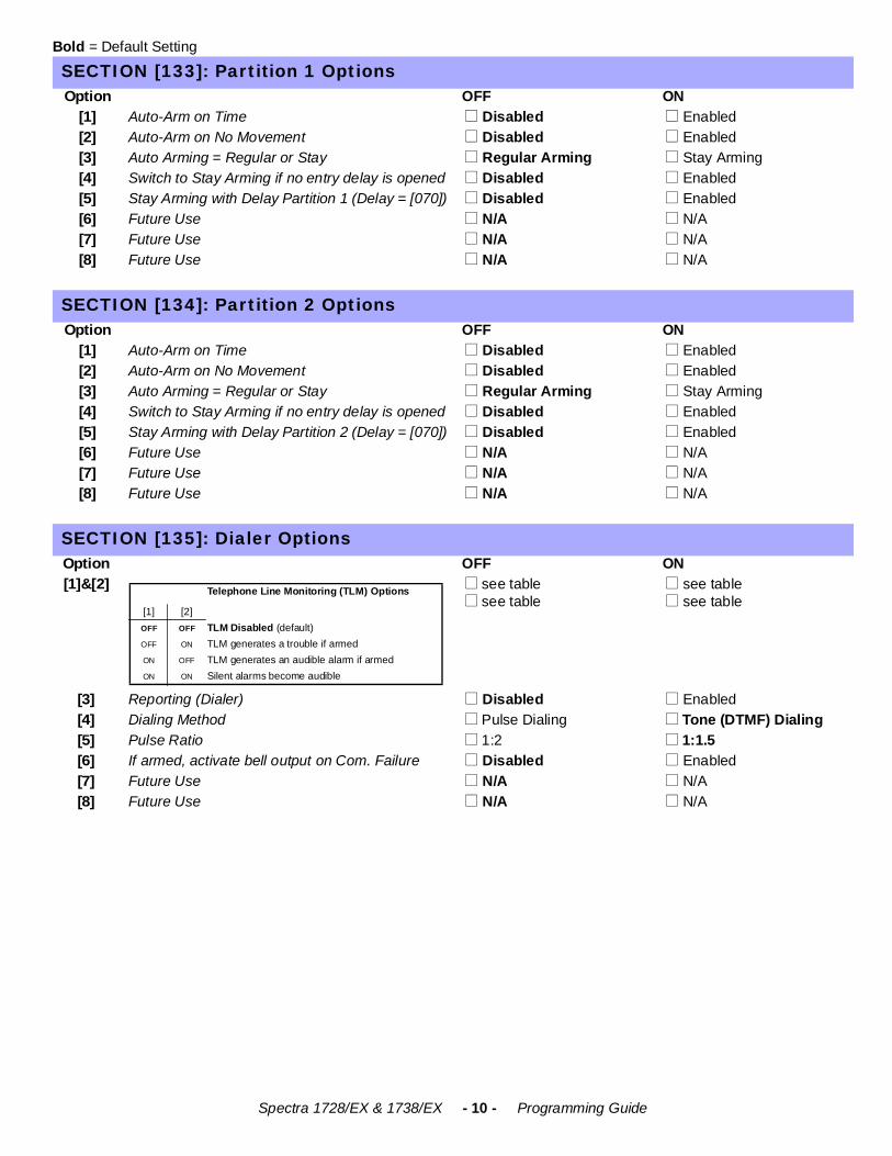
[1] Auto-Arm on Time ! Disabled ! Enabled[2] Auto-Arm on No Movement ! Disabled ! Enabled[3] Auto Arming = Regular or Stay ! Regular Arming ! Stay Arming[4] Switch to Stay Arming if no entry delay is opened ! Disabled ! Enabled[5] Stay Arming with Delay Partition 1 (Delay = [070]) ! Disabled ! Enabled[6] Future Use ! N/A ! N/A[7] Future Use ! N/A ! N/A[8] Future Use ! N/A ! N/A
SECTION [134]: Partition 2 OptionsOption OFF ON
[1] Auto-Arm on Time ! Disabled ! Enabled[2] Auto-Arm on No Movement ! Disabled ! Enabled[3] Auto Arming = Regular or Stay ! Regular Arming ! Stay Arming[4] Switch to Stay Arming if no entry delay is opened ! Disabled ! Enabled[5] Stay Arming with Delay Partition 2 (Delay = [070]) ! Disabled ! Enabled[6] Future Use ! N/A ! N/A[7] Future Use ! N/A ! N/A[8] Future Use ! N/A ! N/A
SECTION [135]: Dialer OptionsOption OFF ON[1]&[2] ! see table
! see table ! see table ! see table
[3] Reporting (Dialer) ! Disabled ! Enabled[4] Dialing Method ! Pulse Dialing ! Tone (DTMF) Dialing[5] Pulse Ratio ! 1:2 ! 1:1.5 [6] If armed, activate bell output on Com. Failure ! Disabled ! Enabled[7] Future Use ! N/A ! N/A[8] Future Use ! N/A ! N/A
Telephone Line Monitoring (TLM) Options
[1] [2]OFF OFF TLM Disabled (default)OFF ON TLM generates a trouble if armedON OFF TLM generates an audible alarm if armedON ON Silent alarms become audible
Spectra 1728/EX & 1738/EX - 11 - Programming Guide
Bold = Default Setting
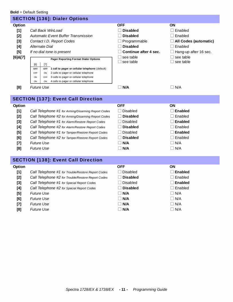
SECTION [136]: Dialer OptionsOption OFF ON
[1] Call Back WinLoad ! Disabled ! Enabled[2] Automatic Event Buffer Transmission ! Disabled ! Enabled[3] Contact I.D. Report Codes ! Programmable ! All Codes (automatic)[4] Alternate Dial ! Disabled ! Enabled[5] If no dial tone is present ! Continue after 4 sec. ! Hang-up after 16 sec.
[6]&[7] ! see table ! see table
! see table ! see table
[8] Future Use ! N/A ! N/A
SECTION [137]: Event Call DirectionOption OFF ON
[1] Call Telephone #1 for Arming/Disarming Report Codes ! Disabled ! Enabled[2] Call Telephone #2 for Arming/Disarming Report Codes ! Disabled ! Enabled[3] Call Telephone #1 for Alarm/Restore Report Codes ! Disabled ! Enabled[4] Call Telephone #2 for Alarm/Restore Report Codes ! Disabled ! Enabled[5] Call Telephone #1 for Tamper/Restore Report Codes ! Disabled ! Enabled[6] Call Telephone #2 for Tamper/Restore Report Codes ! Disabled ! Enabled[7] Future Use ! N/A ! N/A[8] Future Use ! N/A ! N/A
SECTION [138]: Event Call DirectionOption OFF ON
[1] Call Telephone #1 for Trouble/Restore Report Codes ! Disabled ! Enabled[2] Call Telephone #2 for Trouble/Restore Report Codes ! Disabled ! Enabled[3] Call Telephone #1 for Special Report Codes ! Disabled ! Enabled[4] Call Telephone #2 for Special Report Codes ! Disabled ! Enabled[5] Future Use ! N/A ! N/A[6] Future Use ! N/A ! N/A[7] Future Use ! N/A ! N/A[8] Future Use ! N/A ! N/A
Pager Reporting Format Dialer Options
[6] [7]OFF OFF 1 call to pager or cellular telephone (default)OFF ON 2 calls to pager or cellular telephoneON OFF 3 calls to pager or cellular telephoneON ON 4 calls to pager or cellular telephone
Spectra 1728/EX & 1738/EX - 12 - Programming Guide
COMMUNICATION SETTINGS
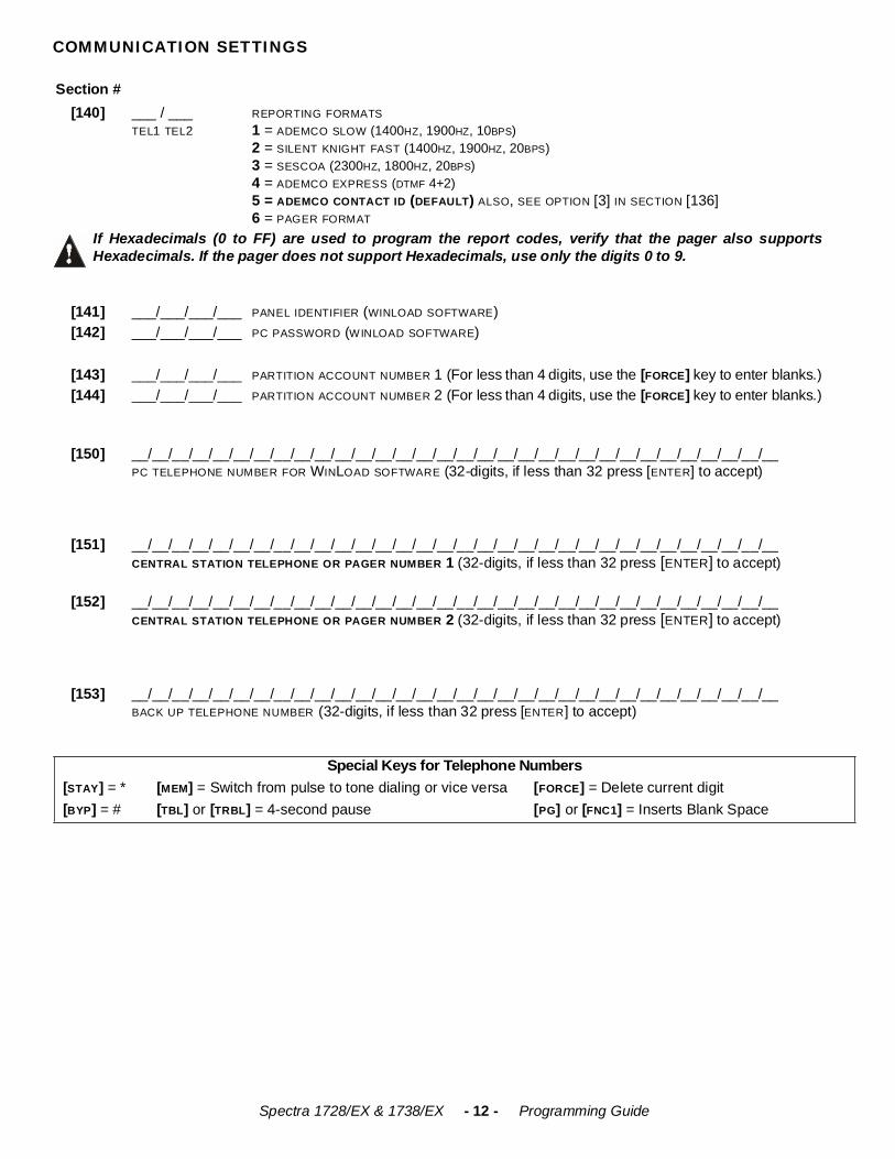
Section #[140] ___ / ___
TEL1 TEL2REPORTING FORMATS1 = ADEMCO SLOW (1400HZ, 1900HZ, 10BPS)2 = SILENT KNIGHT FAST (1400HZ, 1900HZ, 20BPS) 3 = SESCOA (2300HZ, 1800HZ, 20BPS) 4 = ADEMCO EXPRESS (DTMF 4+2)5 = ADEMCO CONTACT ID (DEFAULT) ALSO, SEE OPTION [3] IN SECTION [136]6 = PAGER FORMAT
If Hexadecimals (0 to FF) are used to program the report codes, verify that the pager also supportsHexadecimals. If the pager does not support Hexadecimals, use only the digits 0 to 9.
[141] ___/___/___/___ PANEL IDENTIFIER (WINLOAD SOFTWARE)[142] ___/___/___/___ PC PASSWORD (WINLOAD SOFTWARE)
[143] ___/___/___/___ PARTITION ACCOUNT NUMBER 1 (For less than 4 digits, use the [FORCE] key to enter blanks.)[144] ___/___/___/___ PARTITION ACCOUNT NUMBER 2 (For less than 4 digits, use the [FORCE] key to enter blanks.)
[150] __/__/__/__/__/__/__/__/__/__/__/__/__/__/__/__/__/__/__/__/__/__/__/__/__/__/__/__/__/__/__/__PC TELEPHONE NUMBER FOR WINLOAD SOFTWARE (32-digits, if less than 32 press [ENTER] to accept)
[151] __/__/__/__/__/__/__/__/__/__/__/__/__/__/__/__/__/__/__/__/__/__/__/__/__/__/__/__/__/__/__/__CENTRAL STATION TELEPHONE OR PAGER NUMBER 1 (32-digits, if less than 32 press [ENTER] to accept)
[152] __/__/__/__/__/__/__/__/__/__/__/__/__/__/__/__/__/__/__/__/__/__/__/__/__/__/__/__/__/__/__/__CENTRAL STATION TELEPHONE OR PAGER NUMBER 2 (32-digits, if less than 32 press [ENTER] to accept)
[153] __/__/__/__/__/__/__/__/__/__/__/__/__/__/__/__/__/__/__/__/__/__/__/__/__/__/__/__/__/__/__/__BACK UP TELEPHONE NUMBER (32-digits, if less than 32 press [ENTER] to accept)
Special Keys for Telephone Numbers[STAY] = * [MEM] = Switch from pulse to tone dialing or vice versa [FORCE] = Delete current digit[BYP] = # [TBL] or [TRBL] = 4-second pause [PG] or [FNC1] = Inserts Blank Space
Spectra 1728/EX & 1738/EX - 13 - Programming Guide
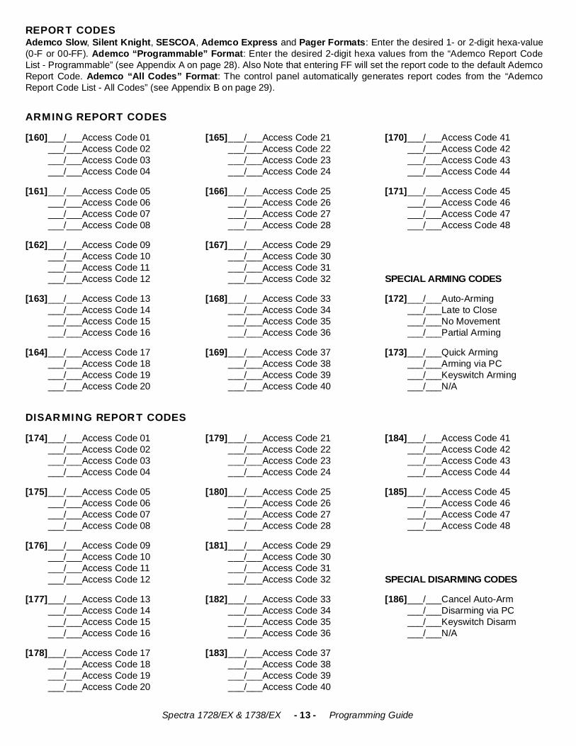
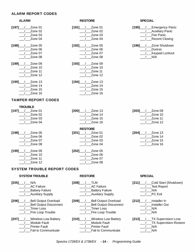
REPORT CODESAdemco Slow, Silent Knight, SESCOA, Ademco Express and Pager Formats: Enter the desired 1- or 2-digit hexa-value(0-F or 00-FF). Ademco “Programmable” Format: Enter the desired 2-digit hexa values from the “Ademco Report CodeList - Programmable” (see Appendix A on page 28). Also Note that entering FF will set the report code to the default AdemcoReport Code. Ademco “All Codes” Format: The control panel automatically generates report codes from the “AdemcoReport Code List - All Codes” (see Appendix B on page 29).
ARMING REPORT CODES
[160]___/___Access Code 01___/___Access Code 02___/___Access Code 03___/___Access Code 04
[165]___/___Access Code 21___/___Access Code 22___/___Access Code 23___/___Access Code 24
[170]___/___Access Code 41___/___Access Code 42___/___Access Code 43___/___Access Code 44
[161]___/___Access Code 05___/___Access Code 06___/___Access Code 07___/___Access Code 08
[166]___/___Access Code 25___/___Access Code 26___/___Access Code 27___/___Access Code 28
[171]___/___Access Code 45___/___Access Code 46___/___Access Code 47___/___Access Code 48
[162]___/___Access Code 09___/___Access Code 10___/___Access Code 11___/___Access Code 12
[167]___/___Access Code 29___/___Access Code 30___/___Access Code 31___/___Access Code 32 SPECIAL ARMING CODES
[163]___/___Access Code 13___/___Access Code 14___/___Access Code 15___/___Access Code 16
[168]___/___Access Code 33___/___Access Code 34___/___Access Code 35___/___Access Code 36
[172]___/___Auto-Arming___/___Late to Close___/___No Movement___/___Partial Arming
[164]___/___Access Code 17___/___Access Code 18___/___Access Code 19___/___Access Code 20
[169]___/___Access Code 37___/___Access Code 38___/___Access Code 39___/___Access Code 40
[173]___/___Quick Arming___/___Arming via PC___/___Keyswitch Arming___/___N/A
DISARMING REPORT CODES
[174]___/___Access Code 01___/___Access Code 02___/___Access Code 03___/___Access Code 04
[179]___/___Access Code 21___/___Access Code 22___/___Access Code 23___/___Access Code 24
[184]___/___Access Code 41___/___Access Code 42___/___Access Code 43___/___Access Code 44
[175]___/___Access Code 05___/___Access Code 06___/___Access Code 07___/___Access Code 08
[180]___/___Access Code 25___/___Access Code 26___/___Access Code 27___/___Access Code 28
[185]___/___Access Code 45___/___Access Code 46___/___Access Code 47___/___Access Code 48
[176]___/___Access Code 09___/___Access Code 10___/___Access Code 11___/___Access Code 12
[181]___/___Access Code 29___/___Access Code 30___/___Access Code 31___/___Access Code 32 SPECIAL DISARMING CODES
[177]___/___Access Code 13___/___Access Code 14___/___Access Code 15___/___Access Code 16
[182]___/___Access Code 33___/___Access Code 34___/___Access Code 35___/___Access Code 36
[186]___/___Cancel Auto-Arm___/___Disarming via PC___/___Keyswitch Disarm___/___N/A
[178]___/___Access Code 17___/___Access Code 18___/___Access Code 19___/___Access Code 20
[183]___/___Access Code 37___/___Access Code 38___/___Access Code 39___/___Access Code 40
Spectra 1728/EX & 1738/EX - 14 - Programming Guide
ALARM REPORT CODES
ALARM RESTORE SPECIAL
[187]___/___Zone 01___/___Zone 02___/___Zone 03___/___Zone 04
[191]___/___Zone 01___/___Zone 02___/___Zone 03___/___Zone 04
[195]___/___Emergency Panic___/___Auxiliary Panic___/___Fire Panic___/___Recent Closing
[188]___/___Zone 05___/___Zone 06___/___Zone 07___/___Zone 08
[192]___/___Zone 05___/___Zone 06___/___Zone 07___/___Zone 08
[196]___/___Zone Shutdown___/___Duress___/___Keypad Lockout___/___N/A
[189]___/___Zone 09___/___Zone 10___/___Zone 11___/___Zone 12
[193]___/___Zone 09___/___Zone 10___/___Zone 11___/___Zone 12
[190]___/___Zone 13___/___Zone 14___/___Zone 15___/___Zone 16
[194]___/___Zone 13___/___Zone 14___/___Zone 15___/___Zone 16
TAMPER REPORT CODES
[197]TROUBLE___/___Zone 01___/___Zone 02___/___Zone 03___/___Zone 04
[200]___/___Zone 13___/___Zone 14___/___Zone 15___/___Zone 16
[203]___/___Zone 09___/___Zone 10___/___Zone 11___/___Zone 12
[198]___/___Zone 05___/___Zone 06___/___Zone 07___/___Zone 08
[201]RESTORE___/___Zone 01___/___Zone 02___/___Zone 03___/___Zone 04
[204]___/___Zone 13___/___Zone 14___/___Zone 15___/___Zone 16
[199]___/___Zone 09___/___Zone 10___/___Zone 11___/___Zone 12
[202]___/___Zone 05___/___Zone 06___/___Zone 07___/___Zone 08
SYSTEM TROUBLE REPORT CODES
SYSTEM TROUBLE RESTORE SPECIAL
[205]___/___N/A___/___AC Failure___/___Battery Failure___/___Auxiliary Supply
[208]___/___TLM___/___AC Failure___/___Battery Failure___/___Auxiliary Supply
[211]___/___Cold Start (Shutdown)___/___Test Report___/___N/A___/___PC Exit
[206]___/___Bell Output Overload___/___Bell Output Disconnect___/___Timer Loss___/___Fire Loop Trouble
[209]___/___Bell Output Overload___/___Bell Output Disconnect___/___Timer Loss___/___Fire Loop Trouble
[212]___/___Installer In___/___Installer Out___/___N/A___/___N/A
[207]___/___Wireless Low Battery___/___Module Fault___/___Printer Fault___/___Fail to Communicate
[210]___/___Wireless Low Battery___/___Module Fault___/___Printer Fault___/___Fail to Communicate
[213]___/___TX Supervision Loss___/___TX Supervision Restore___/___N/A___/___N/A
Spectra 1728/EX & 1738/EX - 15 - Programming Guide
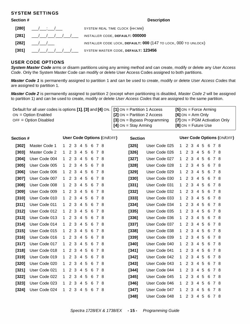
SYSTEM SETTINGS
USER CODE OPTIONSSystem Master Code arms or disarm partitions using any arming method and can create, modify or delete any User AccessCode. Only the System Master Code can modify or delete User Access Codes assigned to both partitions.
Master Code 1 is permanently assigned to partition 1 and can be used to create, modify or delete User Access Codes thatare assigned to partition 1.
Master Code 2 is permanently assigned to partition 2 (except when partitioning is disabled, Master Code 2 will be assignedto partition 1) and can be used to create, modify or delete User Access Codes that are assigned to the same partition.
Section # Description
[280] ___/___:___/___ SYSTEM REAL TIME CLOCK (HH:MM)
[281] ___/___/___/___/___/___ INSTALLER CODE, DEFAULT: 000000
[282] ___/___/___ INSTALLER CODE LOCK, DEFAULT: 000 (147 TO LOCK, 000 TO UNLOCK)
[301] ___/___/___/___/___/___ SYSTEM MASTER CODE, DEFAULT: 123456
Default for all user codes is options [1], [3] and [4] ON.ON = Option EnabledOFF = Option Disabled
[1] ON = Partition 1 Access[2] ON = Partition 2 Access[3] ON = Bypass Programming[4] ON = Stay Arming
[5] ON = Force Arming[6] ON = Arm Only[7] ON = PGM Activation Only[8] ON = Future Use
Section # User Code Options (ON/OFF) Section User Code Options (ON/OFF)
[302] Master Code 1 1 2 3 4 5 6 7 8 [325] User Code 025 1 2 3 4 5 6 7 8[303] Master Code 2 1 2 3 4 5 6 7 8 [326] User Code 026 1 2 3 4 5 6 7 8[304] User Code 004 1 2 3 4 5 6 7 8 [327] User Code 027 1 2 3 4 5 6 7 8[305] User Code 005 1 2 3 4 5 6 7 8 [328] User Code 028 1 2 3 4 5 6 7 8[306] User Code 006 1 2 3 4 5 6 7 8 [329] User Code 029 1 2 3 4 5 6 7 8[307] User Code 007 1 2 3 4 5 6 7 8 [330] User Code 030 1 2 3 4 5 6 7 8[308] User Code 008 1 2 3 4 5 6 7 8 [331] User Code 031 1 2 3 4 5 6 7 8[309] User Code 009 1 2 3 4 5 6 7 8 [332] User Code 032 1 2 3 4 5 6 7 8[310] User Code 010 1 2 3 4 5 6 7 8 [333] User Code 033 1 2 3 4 5 6 7 8[311] User Code 011 1 2 3 4 5 6 7 8 [334] User Code 034 1 2 3 4 5 6 7 8[312] User Code 012 1 2 3 4 5 6 7 8 [335] User Code 035 1 2 3 4 5 6 7 8[313] User Code 013 1 2 3 4 5 6 7 8 [336] User Code 036 1 2 3 4 5 6 7 8[314] User Code 014 1 2 3 4 5 6 7 8 [337] User Code 037 1 2 3 4 5 6 7 8[315] User Code 015 1 2 3 4 5 6 7 8 [338] User Code 038 1 2 3 4 5 6 7 8[316] User Code 016 1 2 3 4 5 6 7 8 [339] User Code 039 1 2 3 4 5 6 7 8[317] User Code 017 1 2 3 4 5 6 7 8 [340] User Code 040 1 2 3 4 5 6 7 8[318] User Code 018 1 2 3 4 5 6 7 8 [341] User Code 041 1 2 3 4 5 6 7 8[319] User Code 019 1 2 3 4 5 6 7 8 [342] User Code 042 1 2 3 4 5 6 7 8[320] User Code 020 1 2 3 4 5 6 7 8 [343] User Code 043 1 2 3 4 5 6 7 8[321] User Code 021 1 2 3 4 5 6 7 8 [344] User Code 044 1 2 3 4 5 6 7 8[322] User Code 022 1 2 3 4 5 6 7 8 [345] User Code 045 1 2 3 4 5 6 7 8[323] User Code 023 1 2 3 4 5 6 7 8 [346] User Code 046 1 2 3 4 5 6 7 8[324] User Code 024 1 2 3 4 5 6 7 8 [347] User Code 047 1 2 3 4 5 6 7 8
[348] User Code 048 1 2 3 4 5 6 7 8
Spectra 1728/EX & 1738/EX - 16 - Programming Guide
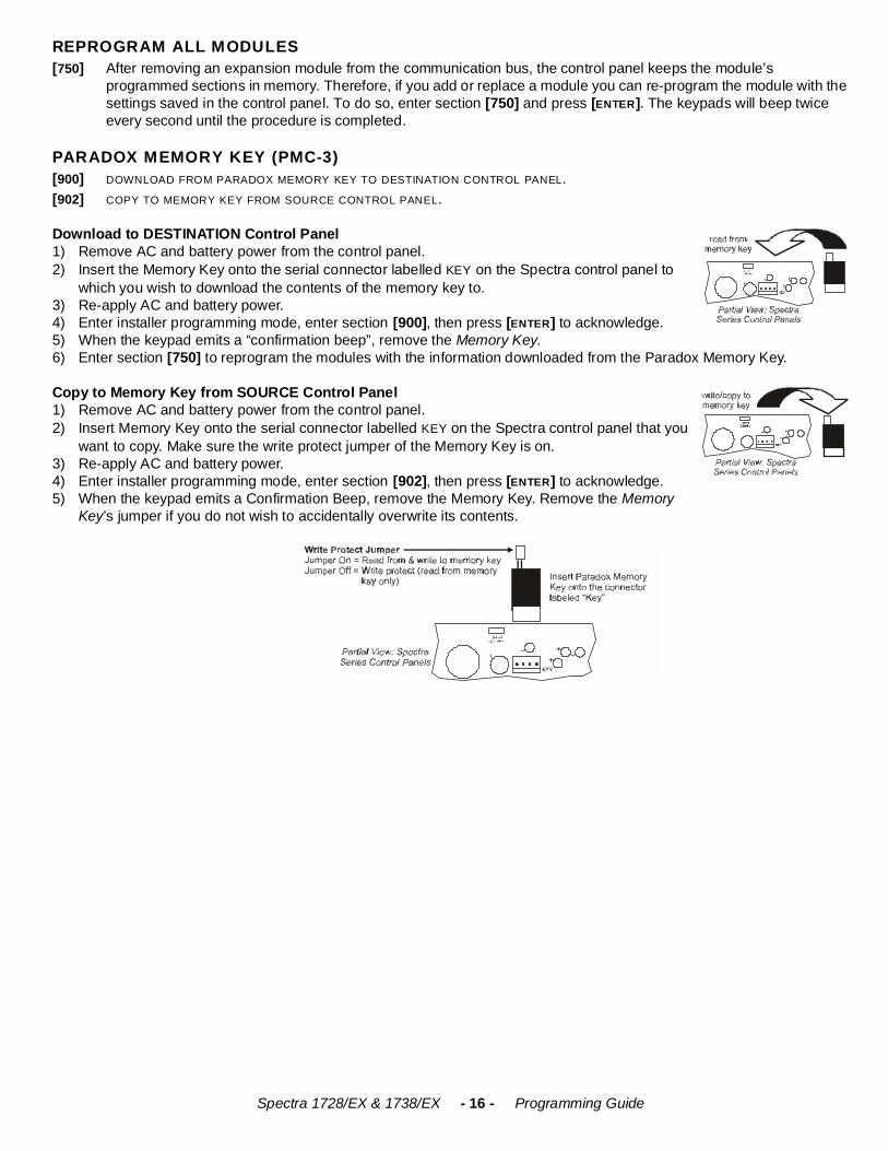
REPROGRAM ALL MODULES
PARADOX MEMORY KEY (PMC-3)
Download to DESTINATION Control Panel1) Remove AC and battery power from the control panel.2) Insert the Memory Key onto the serial connector labelled KEY on the Spectra control panel to
which you wish to download the contents of the memory key to.3) Re-apply AC and battery power. 4) Enter installer programming mode, enter section [900], then press [ENTER] to acknowledge. 5) When the keypad emits a “confirmation beep”, remove the Memory Key.6) Enter section [750] to reprogram the modules with the information downloaded from the Paradox Memory Key.
Copy to Memory Key from SOURCE Control Panel1) Remove AC and battery power from the control panel.2) Insert Memory Key onto the serial connector labelled KEY on the Spectra control panel that you
want to copy. Make sure the write protect jumper of the Memory Key is on.3) Re-apply AC and battery power.4) Enter installer programming mode, enter section [902], then press [ENTER] to acknowledge.5) When the keypad emits a Confirmation Beep, remove the Memory Key. Remove the Memory
Key’s jumper if you do not wish to accidentally overwrite its contents.
[750] After removing an expansion module from the communication bus, the control panel keeps the module’s programmed sections in memory. Therefore, if you add or replace a module you can re-program the module with the settings saved in the control panel. To do so, enter section [750] and press [ENTER]. The keypads will beep twice every second until the procedure is completed.
[900] DOWNLOAD FROM PARADOX MEMORY KEY TO DESTINATION CONTROL PANEL.[902] COPY TO MEMORY KEY FROM SOURCE CONTROL PANEL.
Spectra 1728/EX & 1738/EX - 17 - Programming Guide
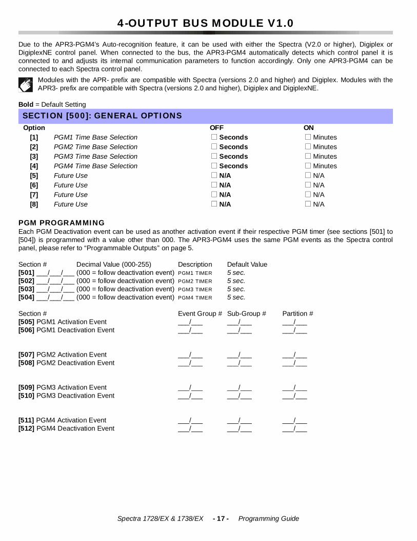
4-OUTPUT BUS MODULE V1.0
Due to the APR3-PGM4’s Auto-recognition feature, it can be used with either the Spectra (V2.0 or higher), Digiplex orDigiplexNE control panel. When connected to the bus, the APR3-PGM4 automatically detects which control panel it isconnected to and adjusts its internal communication parameters to function accordingly. Only one APR3-PGM4 can beconnected to each Spectra control panel.
Modules with the APR- prefix are compatible with Spectra (versions 2.0 and higher) and Digiplex. Modules with theAPR3- prefix are compatible with Spectra (versions 2.0 and higher), Digiplex and DigiplexNE.
Bold = Default Setting
PGM PROGRAMMINGEach PGM Deactivation event can be used as another activation event if their respective PGM timer (see sections [501] to[504]) is programmed with a value other than 000. The APR3-PGM4 uses the same PGM events as the Spectra controlpanel, please refer to “Programmable Outputs” on page 5.
Section # Decimal Value (000-255) Description Default Value [501] ___/___/___ (000 = follow deactivation event) PGM1 TIMER 5 sec.[502] ___/___/___ (000 = follow deactivation event) PGM2 TIMER 5 sec.[503] ___/___/___ (000 = follow deactivation event) PGM3 TIMER 5 sec.[504] ___/___/___ (000 = follow deactivation event) PGM4 TIMER 5 sec.
Section # Event Group # Sub-Group # Partition #[505] PGM1 Activation Event ___/___ ___/___ ___/___[506] PGM1 Deactivation Event ___/___ ___/___ ___/___
[507] PGM2 Activation Event ___/___ ___/___ ___/___[508] PGM2 Deactivation Event ___/___ ___/___ ___/___
[509] PGM3 Activation Event ___/___ ___/___ ___/___[510] PGM3 Deactivation Event ___/___ ___/___ ___/___
[511] PGM4 Activation Event ___/___ ___/___ ___/___[512] PGM4 Deactivation Event ___/___ ___/___ ___/___
SECTION [500]: GENERAL OPTIONSOption OFF ON
[1] PGM1 Time Base Selection ! Seconds ! Minutes[2] PGM2 Time Base Selection ! Seconds ! Minutes[3] PGM3 Time Base Selection ! Seconds ! Minutes[4] PGM4 Time Base Selection ! Seconds ! Minutes[5] Future Use ! N/A ! N/A[6] Future Use ! N/A ! N/A[7] Future Use ! N/A ! N/A[8] Future Use ! N/A ! N/A
Spectra 1728/EX & 1738/EX - 18 - Programming Guide
PRINTER BUS MODULE V1.1
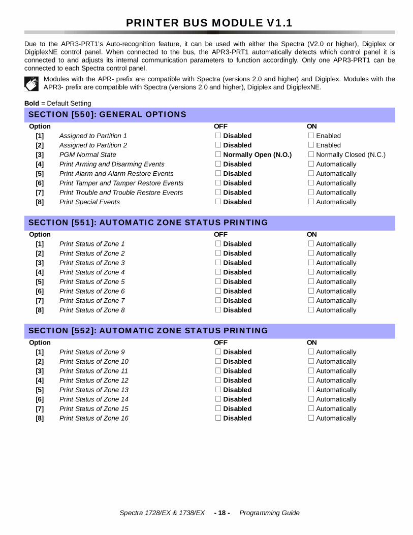
Due to the APR3-PRT1’s Auto-recognition feature, it can be used with either the Spectra (V2.0 or higher), Digiplex orDigiplexNE control panel. When connected to the bus, the APR3-PRT1 automatically detects which control panel it isconnected to and adjusts its internal communication parameters to function accordingly. Only one APR3-PRT1 can beconnected to each Spectra control panel.
Modules with the APR- prefix are compatible with Spectra (versions 2.0 and higher) and Digiplex. Modules with theAPR3- prefix are compatible with Spectra (versions 2.0 and higher), Digiplex and DigiplexNE.
Bold = Default SettingSECTION [550]: GENERAL OPTIONSOption OFF ON
[1] Assigned to Partition 1 ! Disabled ! Enabled[2] Assigned to Partition 2 ! Disabled ! Enabled[3] PGM Normal State ! Normally Open (N.O.) ! Normally Closed (N.C.)[4] Print Arming and Disarming Events ! Disabled ! Automatically[5] Print Alarm and Alarm Restore Events ! Disabled ! Automatically[6] Print Tamper and Tamper Restore Events ! Disabled ! Automatically[7] Print Trouble and Trouble Restore Events ! Disabled ! Automatically[8] Print Special Events ! Disabled ! Automatically
SECTION [551]: AUTOMATIC ZONE STATUS PRINTINGOption OFF ON
[1] Print Status of Zone 1 ! Disabled ! Automatically[2] Print Status of Zone 2 ! Disabled ! Automatically[3] Print Status of Zone 3 ! Disabled ! Automatically[4] Print Status of Zone 4 ! Disabled ! Automatically[5] Print Status of Zone 5 ! Disabled ! Automatically[6] Print Status of Zone 6 ! Disabled ! Automatically[7] Print Status of Zone 7 ! Disabled ! Automatically[8] Print Status of Zone 8 ! Disabled ! Automatically
SECTION [552]: AUTOMATIC ZONE STATUS PRINTINGOption OFF ON
[1] Print Status of Zone 9 ! Disabled ! Automatically[2] Print Status of Zone 10 ! Disabled ! Automatically[3] Print Status of Zone 11 ! Disabled ! Automatically[4] Print Status of Zone 12 ! Disabled ! Automatically[5] Print Status of Zone 13 ! Disabled ! Automatically[6] Print Status of Zone 14 ! Disabled ! Automatically[7] Print Status of Zone 15 ! Disabled ! Automatically[8] Print Status of Zone 16 ! Disabled ! Automatically
Spectra 1728/EX & 1738/EX - 19 - Programming Guide
Bold = Default Setting
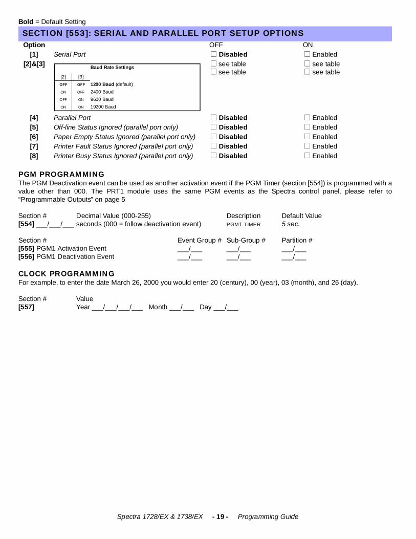
PGM PROGRAMMINGThe PGM Deactivation event can be used as another activation event if the PGM Timer (section [554]) is programmed with avalue other than 000. The PRT1 module uses the same PGM events as the Spectra control panel, please refer to“Programmable Outputs” on page 5
Section # Decimal Value (000-255) Description Default Value [554] ___/___/___ seconds (000 = follow deactivation event) PGM1 TIMER 5 sec.
Section # Event Group # Sub-Group # Partition #[555] PGM1 Activation Event ___/___ ___/___ ___/___[556] PGM1 Deactivation Event ___/___ ___/___ ___/___
CLOCK PROGRAMMINGFor example, to enter the date March 26, 2000 you would enter 20 (century), 00 (year), 03 (month), and 26 (day).
Section # Value [557] Year ___/___/___/___ Month ___/___ Day ___/___
SECTION [553]: SERIAL AND PARALLEL PORT SETUP OPTIONSOption OFF ON
[1] Serial Port ! Disabled ! Enabled[2]&[3] ! see table
! see table ! see table ! see table
[4] Parallel Port ! Disabled ! Enabled[5] Off-line Status Ignored (parallel port only) ! Disabled ! Enabled [6] Paper Empty Status Ignored (parallel port only) ! Disabled ! Enabled[7] Printer Fault Status Ignored (parallel port only) ! Disabled ! Enabled[8] Printer Busy Status Ignored (parallel port only) ! Disabled ! Enabled
Baud Rate Settings
[2] [3]OFF OFF 1200 Baud (default)ON OFF 2400 BaudOFF ON 9600 BaudON ON 19200 Baud
Spectra 1728/EX & 1738/EX - 20 - Programming Guide
VOICE-ASSISTED ARM/DISARM BUS MODULE V1.0
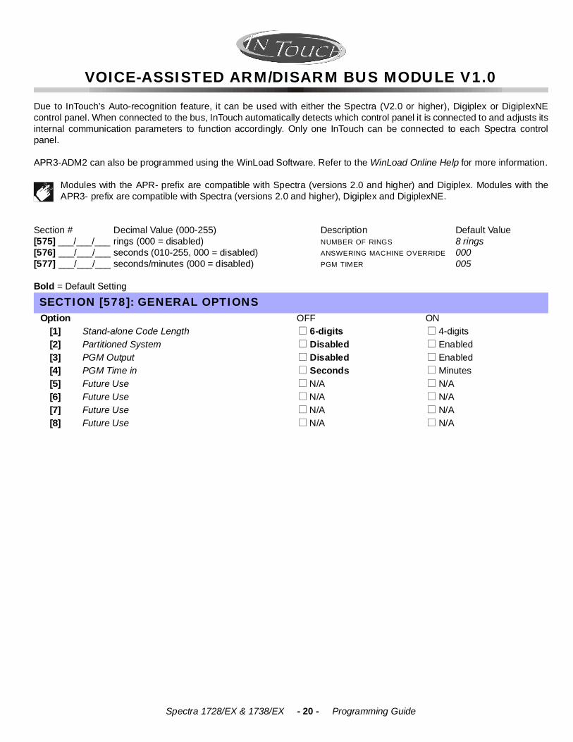
Due to InTouch’s Auto-recognition feature, it can be used with either the Spectra (V2.0 or higher), Digiplex or DigiplexNEcontrol panel. When connected to the bus, InTouch automatically detects which control panel it is connected to and adjusts itsinternal communication parameters to function accordingly. Only one InTouch can be connected to each Spectra controlpanel.
APR3-ADM2 can also be programmed using the WinLoad Software. Refer to the WinLoad Online Help for more information.
Modules with the APR- prefix are compatible with Spectra (versions 2.0 and higher) and Digiplex. Modules with theAPR3- prefix are compatible with Spectra (versions 2.0 and higher), Digiplex and DigiplexNE.
Section # Decimal Value (000-255) Description Default Value [575] ___/___/___ rings (000 = disabled) NUMBER OF RINGS 8 rings[576] ___/___/___ seconds (010-255, 000 = disabled) ANSWERING MACHINE OVERRIDE 000 [577] ___/___/___ seconds/minutes (000 = disabled) PGM TIMER 005
Bold = Default Setting
SECTION [578]: GENERAL OPTIONSOption OFF ON
[1] Stand-alone Code Length ! 6-digits ! 4-digits[2] Partitioned System ! Disabled ! Enabled[3] PGM Output ! Disabled ! Enabled[4] PGM Time in ! Seconds ! Minutes[5] Future Use ! N/A ! N/A [6] Future Use ! N/A ! N/A [7] Future Use ! N/A ! N/A [8] Future Use ! N/A ! N/A
Spectra 1728/EX & 1738/EX - 21 - Programming Guide
900MHZ WIRELESS BUS MODULE V1.0
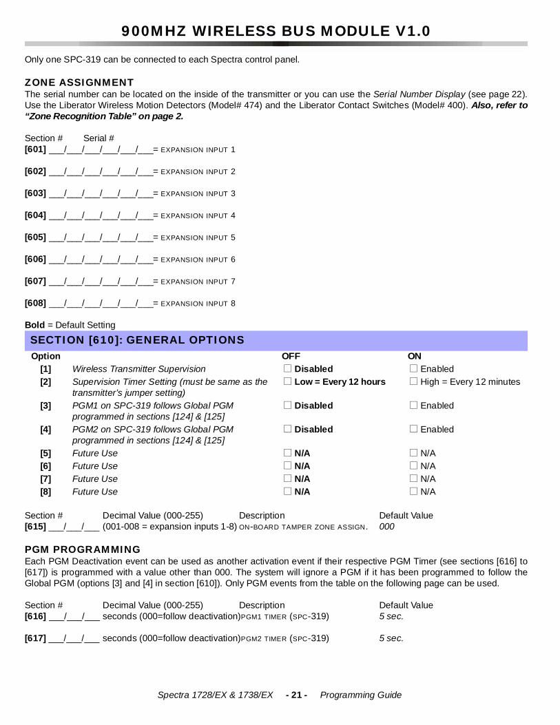
Only one SPC-319 can be connected to each Spectra control panel.
ZONE ASSIGNMENT The serial number can be located on the inside of the transmitter or you can use the Serial Number Display (see page 22).Use the Liberator Wireless Motion Detectors (Model# 474) and the Liberator Contact Switches (Model# 400). Also, refer to“Zone Recognition Table” on page 2. Section # Serial #[601] ___/___/___/___/___/___= EXPANSION INPUT 1
[602] ___/___/___/___/___/___= EXPANSION INPUT 2
[603] ___/___/___/___/___/___= EXPANSION INPUT 3
[604] ___/___/___/___/___/___= EXPANSION INPUT 4
[605] ___/___/___/___/___/___= EXPANSION INPUT 5
[606] ___/___/___/___/___/___= EXPANSION INPUT 6
[607] ___/___/___/___/___/___= EXPANSION INPUT 7
[608] ___/___/___/___/___/___= EXPANSION INPUT 8
Bold = Default Setting
Section # Decimal Value (000-255) Description Default Value [615] ___/___/___ (001-008 = expansion inputs 1-8) ON-BOARD TAMPER ZONE ASSIGN. 000
PGM PROGRAMMING Each PGM Deactivation event can be used as another activation event if their respective PGM Timer (see sections [616] to[617]) is programmed with a value other than 000. The system will ignore a PGM if it has been programmed to follow theGlobal PGM (options [3] and [4] in section [610]). Only PGM events from the table on the following page can be used.
Section # Decimal Value (000-255) Description Default Value [616] ___/___/___ seconds (000=follow deactivation)PGM1 TIMER (SPC-319) 5 sec.
[617] ___/___/___ seconds (000=follow deactivation)PGM2 TIMER (SPC-319) 5 sec.
SECTION [610]: GENERAL OPTIONS Option OFF ON
[1] Wireless Transmitter Supervision ! Disabled ! Enabled[2] Supervision Timer Setting (must be same as the
transmitter’s jumper setting) ! Low = Every 12 hours ! High = Every 12 minutes
[3] PGM1 on SPC-319 follows Global PGM programmed in sections [124] & [125]
! Disabled ! Enabled
[4] PGM2 on SPC-319 follows Global PGM programmed in sections [124] & [125]
! Disabled ! Enabled
[5] Future Use ! N/A ! N/A[6] Future Use ! N/A ! N/A[7] Future Use ! N/A ! N/A[8] Future Use ! N/A ! N/A
Spectra 1728/EX & 1738/EX - 22 - Programming Guide
Section # Event Group Sub-Group Partition[620] PGM1 Activation Event ___/___ ___/___ ___/___[621] PGM1 Deactivation Event ___/___ ___/___ ___/___
[622] PGM2 Activation Event ___/___ ___/___ ___/___[623] PGM2 Deactivation Event ___/___ ___/___ ___/___
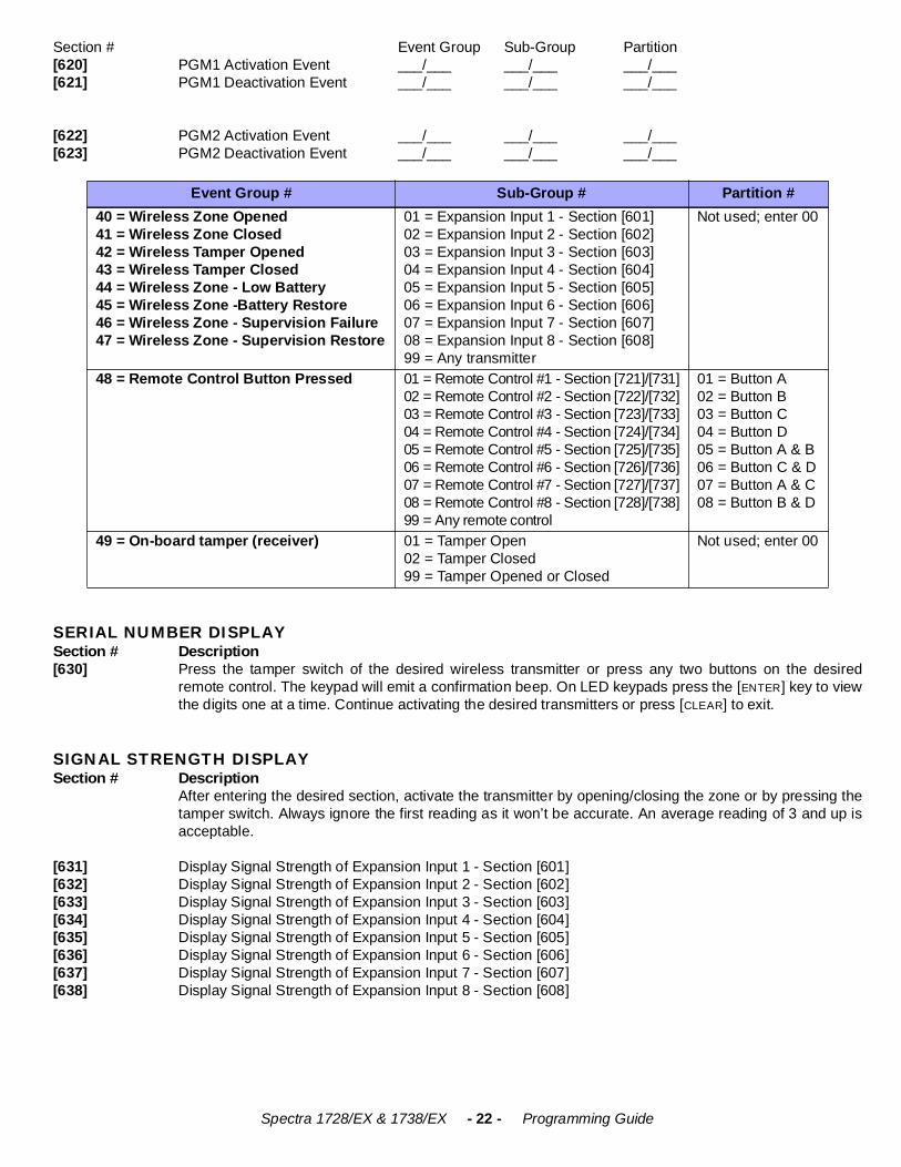
SERIAL NUMBER DISPLAYSection # Description [630] Press the tamper switch of the desired wireless transmitter or press any two buttons on the desired
remote control. The keypad will emit a confirmation beep. On LED keypads press the [ENTER] key to viewthe digits one at a time. Continue activating the desired transmitters or press [CLEAR] to exit.
SIGNAL STRENGTH DISPLAYSection # Description
After entering the desired section, activate the transmitter by opening/closing the zone or by pressing thetamper switch. Always ignore the first reading as it won’t be accurate. An average reading of 3 and up isacceptable.
[631] Display Signal Strength of Expansion Input 1 - Section [601][632] Display Signal Strength of Expansion Input 2 - Section [602][633] Display Signal Strength of Expansion Input 3 - Section [603][634] Display Signal Strength of Expansion Input 4 - Section [604][635] Display Signal Strength of Expansion Input 5 - Section [605][636] Display Signal Strength of Expansion Input 6 - Section [606][637] Display Signal Strength of Expansion Input 7 - Section [607][638] Display Signal Strength of Expansion Input 8 - Section [608]
Event Group # Sub-Group # Partition #40 = Wireless Zone Opened41 = Wireless Zone Closed42 = Wireless Tamper Opened43 = Wireless Tamper Closed44 = Wireless Zone - Low Battery45 = Wireless Zone -Battery Restore46 = Wireless Zone - Supervision Failure47 = Wireless Zone - Supervision Restore
01 = Expansion Input 1 - Section [601]02 = Expansion Input 2 - Section [602]03 = Expansion Input 3 - Section [603]04 = Expansion Input 4 - Section [604]05 = Expansion Input 5 - Section [605]06 = Expansion Input 6 - Section [606]07 = Expansion Input 7 - Section [607]08 = Expansion Input 8 - Section [608]99 = Any transmitter
Not used; enter 00
48 = Remote Control Button Pressed 01 = Remote Control #1 - Section [721]/[731]02 = Remote Control #2 - Section [722]/[732]03 = Remote Control #3 - Section [723]/[733]04 = Remote Control #4 - Section [724]/[734]05 = Remote Control #5 - Section [725]/[735]06 = Remote Control #6 - Section [726]/[736]07 = Remote Control #7 - Section [727]/[737]08 = Remote Control #8 - Section [728]/[738]99 = Any remote control
01 = Button A02 = Button B03 = Button C04 = Button D05 = Button A & B06 = Button C & D07 = Button A & C08 = Button B & D
49 = On-board tamper (receiver) 01 = Tamper Open02 = Tamper Closed99 = Tamper Opened or Closed
Not used; enter 00
Spectra 1728/EX & 1738/EX - 23 - Programming Guide
REMOTE CONTROL USER ASSIGNMENT
Section # Decimal Value Description Default Value [701] ___/___/___(001-048 = user #) remote control #1 - section [721] 000[702] ___/___/___(001-048 = user #) remote control #2 - section [722] 000[703] ___/___/___(001-048 = user #) remote control #3 - section [723] 000[704] ___/___/___(001-048 = user #) remote control #4 - section [724] 000[705] ___/___/___(001-048 = user #) remote control #5 - section [725] 000[706] ___/___/___(001-048 = user #) remote control #6 - section [726] 000[707] ___/___/___(001-048 = user #) remote control #7 - section [727] 000[708] ___/___/___(001-048 = user #) remote control #8 - section [728] 000
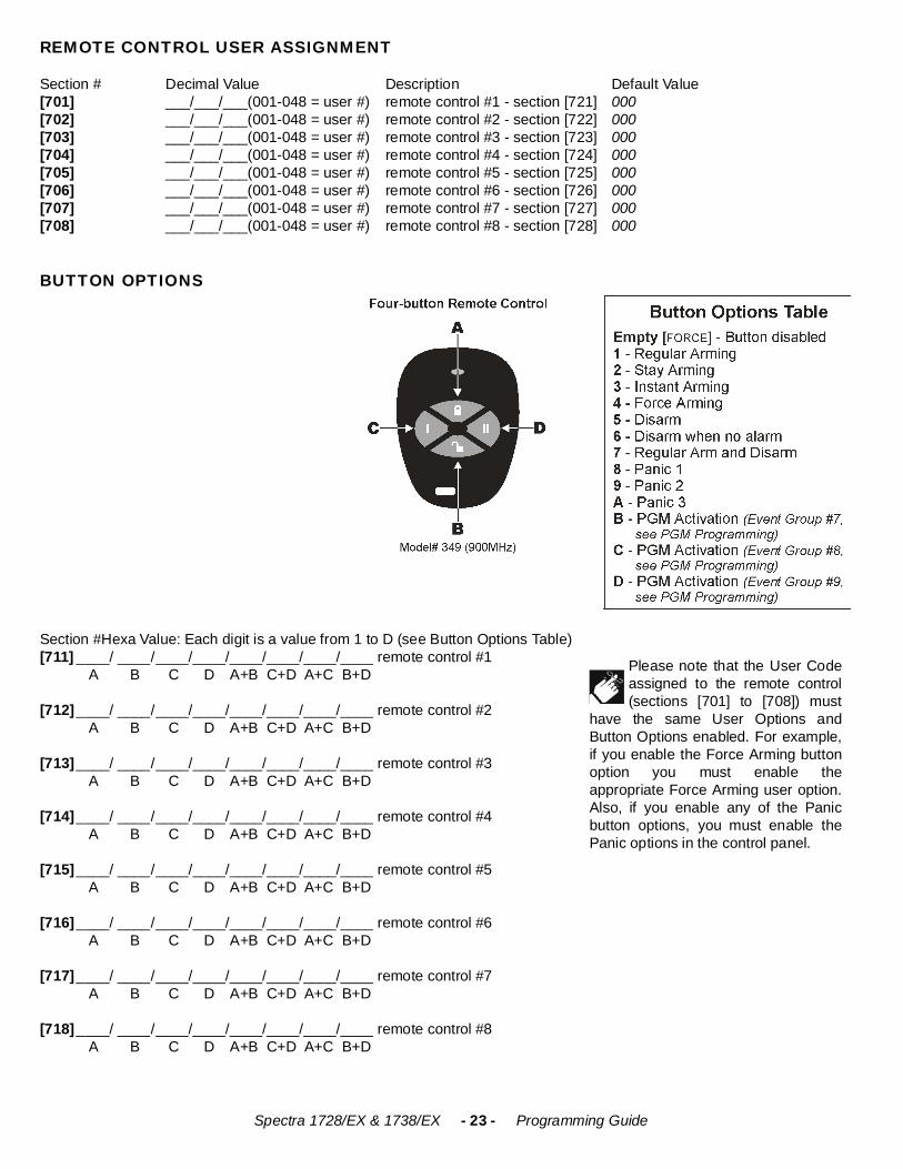
BUTTON OPTIONS
Section #Hexa Value: Each digit is a value from 1 to D (see Button Options Table)[711] ____/ ____/____/____/____/____/____/____ remote control #1
A B C D A+B C+D A+C B+D
[712]____/ ____/____/____/____/____/____/____ remote control #2 A B C D A+B C+D A+C B+D
[713]____/ ____/____/____/____/____/____/____ remote control #3 A B C D A+B C+D A+C B+D
[714]____/ ____/____/____/____/____/____/____ remote control #4 A B C D A+B C+D A+C B+D
[715]____/ ____/____/____/____/____/____/____ remote control #5 A B C D A+B C+D A+C B+D
[716]____/ ____/____/____/____/____/____/____ remote control #6 A B C D A+B C+D A+C B+D
[717]____/ ____/____/____/____/____/____/____ remote control #7 A B C D A+B C+D A+C B+D
[718]____/ ____/____/____/____/____/____/____ remote control #8 A B C D A+B C+D A+C B+D
Please note that the User Codeassigned to the remote control(sections [701] to [708]) must
have the same User Options andButton Options enabled. For example,if you enable the Force Arming buttonoption you must enable theappropriate Force Arming user option.Also, if you enable any of the Panicbutton options, you must enable thePanic options in the control panel.
Spectra 1728/EX & 1738/EX - 24 - Programming Guide
REMOTE CONTROL ASSIGNMENT Use the Serial Number Display (see page 22) to find out the serial number of a remote control. If you hear rejection beep, anerror has occurred or the remote control has already been assigned. To delete a remote control, enter the desired sectionthen enter a value of 000000.
Section # Serial #[721] ___/___/___/___/___/___ REMOTE CONTROL #1
[722] ___/___/___/___/___/___ REMOTE CONTROL #2
[723] ___/___/___/___/___/___ REMOTE CONTROL #3
[724] ___/___/___/___/___/___ REMOTE CONTROL #4
[725] ___/___/___/___/___/___ REMOTE CONTROL #5
[726] ___/___/___/___/___/___ REMOTE CONTROL #6
[727] ___/___/___/___/___/___ REMOTE CONTROL #7
[728] ___/___/___/___/___/___ REMOTE CONTROL #8
Spectra 1728/EX & 1738/EX - 25 - Programming Guide
ZONE EXPANSION BUS MODULES
Only one SPC/APR3-ZX4 or one SPC/APR3-ZX8 can be connected to each Spectra control panel. The following sectionsare for SPC-ZX4 version 1.0, APR3-ZX4 version 1.0, SPC-ZX8 version 1.0 and APR3-ZX8 version 1.4.
Modules with the APR- prefix are compatible with Spectra (versions 2.0 and higher) and Digiplex. Modules with theAPR3- prefix are compatible with Spectra (versions 2.0 and higher), Digiplex and DigiplexNE.
Bold = Default Setting
PGM PROGRAMMING (SPC-ZX8 and APR3-ZX8 Only)The PGM will only activate or deactivate 100mS after the selected event occurs. The PGM Deactivation event can be usedas another activation event if the PGM Timer (section [655]) is programmed with a value other than 000. The system willignore the PGM if it has been programmed to follow the Global PGM (option [3] in section [650]). Only PGM events from thetable below can be used.
Section # Decimal Value (000-255) Description Default Value [655] ___/___/___ seconds (000 = follow deactivation event) PGM1 TIMER 5 sec.
Section # Event Group # Sub-Group # Partition #[656] PGM1 Activation Event ___/___ ___/___ ___/___[657] PGM1 Deactivation Event ___/___ ___/___ ___/___
SECTION [650]: OptionsOption OFF ON
[1] EOL (end-of-line) Resistors for hardwire modules ! No EOL ! Use EOL Resistors [2] Zone Expansion Module Tamper Recognition ! Disabled ! Z1 becomes tamper input [3] PGM1 on SPC/APR3-ZX8 follows Global PGM
programmed in sections [124] & [125] ! Disabled ! Enabled
[4]-[8] Future Use ! N/A ! N/A
SECTION [651]: ZONE ASSIGNMENTOption See “Zone Recognition Table” on page 2. OFF ON
[1] Input Z1 =Expansion Input 1 ! Disabled ! Enabled[2] Input Z2 =Expansion Input 2 ! Disabled ! Enabled[3] Input Z3 =Expansion Input 3 ! Disabled ! Enabled[4] Input Z4 =Expansion Input 4 ! Disabled ! Enabled[5] Input Z5 (SPC/APR3-ZX8 only) =Expansion Input 5 ! Disabled ! Enabled[6] Input Z6 (SPC/APR3-ZX8 only) =Expansion Input 6 ! Disabled ! Enabled[7] Input Z7 (SPC/APR3-ZX8 only) =Expansion Input 7 ! Disabled ! Enabled[8] Input Z8 (SPC/APR3-ZX8 only) =Expansion Input 8 ! Disabled ! Enabled
Event Group # Sub-Group # Partition #For SPC-ZX8:60 = Hardwire Zone Opened61 = Hardwire Zone Closed62 = Hardwire Tamper Opened63 = Hardwire Tamper Closed
For APR3-ZX8:60 = Hardwire Zone/Hardwire Tamper Opened61 = Hardwire Zone/Hardwire Tamper Closed
01 = Expansion Input 1 - Section [651] - [1]02 = Expansion Input 2 - Section [651] - [2]03 = Expansion Input 3 - Section [651] - [3]04 = Expansion Input 4 - Section [651] - [4]05 = Expansion Input 5 - Section [651] - [5]06 = Expansion Input 6 - Section [651] - [6]07 = Expansion Input 7 - Section [651] - [7]08 = Expansion Input 8 - Section [651] - [8]99 = Any zone expansion bus module input
Not used; enter 00
Spectra 1728/EX & 1738/EX - 26 - Programming Guide
USER OPERATION
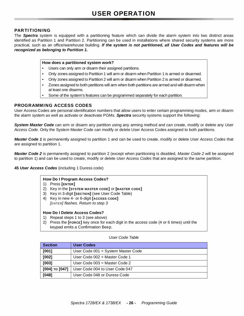
PARTITIONINGThe Spectra system is equipped with a partitioning feature which can divide the alarm system into two distinct areasidentified as Partition 1 and Partition 2. Partitioning can be used in installations where shared security systems are morepractical, such as an office/warehouse building. If the system is not partitioned, all User Codes and features will berecognized as belonging to Partition 1.
PROGRAMMING ACCESS CODESUser Access Codes are personal identification numbers that allow users to enter certain programming modes, arm or disarmthe alarm system as well as activate or deactivate PGMs. Spectra security systems support the following:
System Master Code can arm or disarm any partition using any arming method and can create, modify or delete any UserAccess Code. Only the System Master Code can modify or delete User Access Codes assigned to both partitions.
Master Code 1 is permanently assigned to partition 1 and can be used to create, modify or delete User Access Codes thatare assigned to partition 1.
Master Code 2 is permanently assigned to partition 2 (except when partitioning is disabled, Master Code 2 will be assignedto partition 1) and can be used to create, modify or delete User Access Codes that are assigned to the same partition.
45 User Access Codes (including 1 Duress code)
How does a partitioned system work?• Users can only arm or disarm their assigned partitions.• Only zones assigned to Partition 1 will arm or disarm when Partition 1 is armed or disarmed.• Only zones assigned to Partition 2 will arm or disarm when Partition 2 is armed or disarmed.• Zones assigned to both partitions will arm when both partitions are armed and will disarm when
at least one disarms.• Some of the system’s features can be programmed separately for each partition.
How Do I Program Access Codes?1) Press [ENTER]2) Key in the [SYSTEM MASTER CODE] or [MASTER CODE] 3) Key in 3-digit [SECTION] (see User Code Table)4) Key in new 4- or 6-digit [ACCESS CODE]
[ENTER] flashes. Return to step 3
How Do I Delete Access Codes?1) Repeat steps 1 to 3 (see above)2) Press the [FORCE] key once for each digit in the access code (4 or 6 times) until the
keypad emits a Confirmation Beep.
User Code Table
Section User Codes[001] User Code 001 = System Master Code[002] User Code 002 = Master Code 1[003] User Code 003 = Master Code 2[004] TO [047] User Code 004 to User Code 047[048] User Code 048 or Duress Code
Spectra 1728/EX & 1738/EX - 27 - Programming Guide
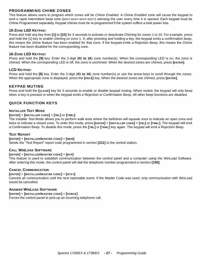
PROGRAMMING CHIME ZONESThis feature allows users to program which zones will be Chime Enabled. A Chime Enabled zone will cause the keypad toemit a rapid intermittent beep tone (BEEP-BEEP-BEEP-BEEP) advising the user every time it is opened. Each keypad must beChime Programmed separately. Keypad chimes must be re-programmed if the system suffers a total power loss.
10-ZONE LED KEYPAD:Press and hold any key from [1] to [10] for 3 seconds to activate or deactivate Chiming for zones 1 to 10. For example, pressand hold the [1] key to enable chiming on zone 1. If, after pressing and holding a key, the keypad emits a confirmation beep,this means the chime feature has been enabled for that zone. If the keypad emits a Rejection Beep, this means the Chimefeature has been disabled for the corresponding zone.
16-ZONE LED KEYPAD:Press and hold the [9] key. Enter the 2-digit (01 to 16) zone number(s). When the corresponding LED is on, the zone ischimed. When the corresponding LED is off, the zone is unchimed. When the desired zones are chimed, press [ENTER].
LCD KEYPAD:Press and hold the [9] key. Enter the 2-digit (01 to 16) zone number(s) or use the arrow keys to scroll through the zones.When the appropriate zone is displayed, press the [FNC1] key. When the desired zones are chimed, press [ENTER].
KEYPAD MUTINGPress and hold the [CLEAR] key for 3 seconds to enable or disable keypad muting. When muted, the keypad will only beepwhen a key is pressed or when the keypad emits a Rejection or Confirmation Beep. All other beep functions are disabled.
QUICK FUNCTION KEYS
INSTALLER TEST MODE[ENTER] + [INSTALLER CODE] + [TBL] or [TRBL]The Installer Test Mode allows you to perform walk tests where the bell/siren will squawk once to indicate an open zone andtwice to indicate a closed zone. To enter this mode, press [ENTER] + [INSTALLER CODE] + [TBL] or [TRBL]. The keypad will emita Confirmation Beep. To disable this mode, press the [TBL] or [TRBL] key again. The keypad will emit a Rejection Beep.
TEST REPORT[ENTER] + [INSTALLER/MASTER CODE] + [MEM] Sends the “Test Report” report code programmed in section [211] to the central station.
CALL WINLOAD SOFTWARE [ENTER] + [INSTALLER/MASTER CODE] + [BYP]This feature is used to establish communication between the control panel and a computer using the WinLoad Software.After entering this mode, the control panel will dial the telephone number programmed in section [150].
CANCEL COMMUNICATION[ENTER] + [INSTALLER/MASTER CODE] + [STAY]Cancels all communication until the next reportable event. If the Master Code was used, only communication with WinLoadwould be cancelled.
ANSWER WINLOAD SOFTWARE [ENTER] + [INSTALLER/MASTER CODE] + [FORCE]Forces the control panel to pick-up an incoming telephone call.
Spectra 1728/EX & 1738/EX - 28 - Programming Guide
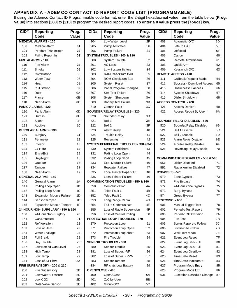
APPENDIX A - ADEMCO CONTACT ID REPORT CODE LIST (PROGRAMMABLE)If using the Ademco Contact ID Programmable code format, enter the 2-digit hexadecimal value from the table below (Prog.Value) into sections [160] to [213] to program the desired report codes. To enter a 0 value press the [FORCE] key.
CID# Reporting Prog.Code Value
CID# Reporting Prog.Code Value
CID# Reporting Prog.Code Value
MEDICAL ALARMS - 100 204 Low Water Level 2F 403 Automatic O/C 5D100 Medical Alarm 01 205 Pump Activated 30 404 Late to O/C 5E101 Pendant Transmitter 02 206 Pump Failure 31 405 Deferred 5F102 Fail to Report In 03 SYSTEM TROUBLES - 300 & 310 406 Cancel 60
FIRE ALARMS - 110 300 System Trouble 32 407 Remote Arm/Disarm 61110 Fire Alarm 04 301 AC Loss 33 408 Quick Arm 62111 Smoke 05 302 Low System Battery 34 409 Keyswitch O/C 63112 Combustion 06 303 RAM Checksum Bad 35 REMOTE ACCESS - 410113 Water Flow 07 304 ROM Checksum Bad 36 411 Callback Request Made 64114 Heat 08 305 System Reset 37 412 Success - Download Access 65115 Pull Station 09 306 Panel Program Changed 38 413 Unsuccessful Access 66116 Duct 0A 307 Self-Test Failure 39 414 System Shutdown 67117 Flame 0B 308 System Shutdown 3A 415 Dialer Shutdown 68118 Near Alarm 0C 309 Battery Test Failure 3B ACCESS CONTROL - 420
PANIC ALARMS - 120 310 Ground Fault 3C 421 Access Denied 69120 Panic Alarm 0D SOUNDER/RELAY TROUBLES - 320 422 Access Report By User 6A121 Duress 0E 320 Sounder Relay 3D122 Silent 0F 321 Bell 1 3E SOUNDER RELAY DISABLES - 520123 Audible 10 322 Bell 2 3F 520 Sounder/Relay Disabled 6B
BURGLAR ALARMS - 130 323 Alarm Relay 40 521 Bell 1 Disable 6C130 Burglary 11 324 Trouble Relay 41 522 Bell 2 Disable 6D131 Perimeter 12 325 Reversing 42 523 Alarm Relay Disable 6E132 Interior 13 SYSTEM PERIPHERAL TROUBLES - 330 & 340 524 Trouble Relay Disable 6F133 24-Hour 14 330 System Peripheral 43 525 Reversing Relay Disable 70134 Entry/Exit 15 331 Polling Loop Open 44135 Day/Night 16 332 Polling Loop Short 45 COMMUNICATION DISABLES - 550 & 560136 Outdoor 17 333 Exp. Module Failure 46 551 Dialer Disabled 71137 Tamper 18 334 Repeater Failure 47 552 Radio xmitter Disabled 72138 Near Alarm 19 335 Local Printer Paper Out 48 BYPASSES - 570
GENERAL ALARMS - 140 336 Local Printer Failure 49 570 Zone Bypass 73140 General Alarm 1A COMMUNICATION TROUBLES - 350 & 360 571 Fire Bypass 74141 Polling Loop Open 1B 350 Communication 4A 572 24-Hour Zone Bypass 75142 Polling Loop Short 1C 351 Telco Fault 1 4B 573 Burg. Bypass 76143 Expansion Module Failure 1D 352 Telco Fault 2 4C 574 Group Bypass 77144 Sensor Tamper 1E 353 Long Range Radio 4D TEST/MISC. - 600145 Expansion Module Tamper 1F 354 Fail to Communicate 4E 601 Manual Trigger Test 78
24-HOUR NON-BURGLARY - 150 & 160 355 Loss of Radio Supervision 4F 602 Periodic Test Report 79150 24-Hour Non-Burglary 20 356 Loss of Central Polling 50 603 Periodic RF Xmission 7A151 Gas Detected 21 PROTECTION LOOP TROUBLES - 370 604 Fire Test 7B152 Refrigeration 22 370 Protection Loop 51 605 Status Report to Follow 7C153 Loss of Heat 23 371 Protection Loop Open 52 606 Listen-in to Follow 7D154 Water Leakage 24 372 Protection Loop short 53 607 Walk Test Mode 7E155 Foil Break 25 373 Fire Trouble 54 621 Event Log Reset 7F156 Day Trouble 26 SENSOR TROUBLES - 380 622 Event Log 50% Full 80157 Low Bottled Gas Level 27 380 Sensor Trouble 55 623 Event Log 90% Full 81158 High Temp 28 381 Loss of Super. -RF 56 624 Event Log Overflow 82159 Low Temp 29 382 Loss of Super. - RPM 57 625 Time/Date Reset 83161 Loss of Air Flow 2A 383 Sensor Tamper 58 626 Time/Date Inaccurate 84
FIRE SUPERVISORY - 200 & 210 384 RF xmtr. Low Battery 59 627 Program Mode Entry 85200 Fire Supervisory 2B OPEN/CLOSE - 400 628 Program Mode Exit 86201 Low Water Pressure 2C 400 Open/Close 5A 631 Exception Schedule Change 87202 Low CO2 2D 401 O/C by User 5B203 Gate Valve Sensor 2E 402 Group O/C 5C
Spectra 1728/EX & 1738/EX - 29 - Programming Guide
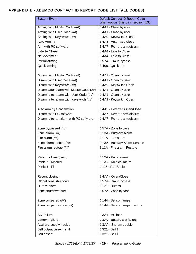
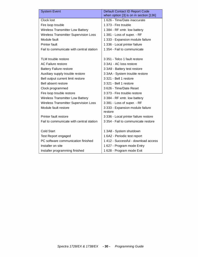
APPENDIX B - ADEMCO CONTACT ID REPORT CODE LIST (ALL CODES)
System Event Default Contact ID Report Codewhen option [3] is on in section [136]
Arming with Master Code (##) 3 4A1 - Close by userArming with User Code (##) 3 4A1 - Close by userArming with Keyswitch (##) 3 4A9 - Keyswitch CloseAuto Arming 3 4A3 - Automatic CloseArm with PC software 3 4A7 - Remote arm/disarmLate To Close 3 4A4 - Late to CloseNo Movement 3 4A4 - Late to ClosePartial arming 1 574 - Group bypassQuick arming 3 408 - Quick arm
Disarm with Master Code (##) 1 4A1 - Open by userDisarm with User Code (##) 1 4A1 - Open by userDisarm with Keyswitch (##) 1 4A9 - Keyswitch OpenDisarm after alarm with Master Code (##) 1 4A1 - Open by userDisarm after alarm with User Code (##) 1 4A1 - Open by userDisarm after alarm with Keyswitch (##) 1 4A9 - Keyswitch Open
Auto Arming Cancellation 1 4A5 - Deferred Open/CloseDisarm with PC software 1 4A7 - Remote arm/disarmDisarm after an alarm with PC software 1 4A7 - Remote arm/disarm
Zone Bypassed (##) 1 57A - Zone bypassZone alarm (##) 1 13A - Burglary AlarmFire alarm (##) 1 11A - Fire alarmZone alarm restore (##) 3 13A - Burglary Alarm RestoreFire alarm restore (##) 3 11A - Fire alarm Restore
Panic 1 - Emergency 1 12A - Panic alarmPanic 2 - Medical 1 1AA - Medical alarmPanic 3 - Fire 1 115 - Pull Station
Recent closing 3 4AA - Open/CloseGlobal zone shutdown 1 574 - Group bypassDuress alarm 1 121 - DuressZone shutdown (##) 1 57A - Zone bypass
Zone tampered (##) 1 144 - Sensor tamperZone tamper restore (##) 3 144 - Sensor tamper restore
AC Failure 1 3A1 - AC lossBattery Failure 1 3A9 - Battery test failureAuxiliary supply trouble 1 3AA - System troubleBell output current limit 1 321 - Bell 1Bell absent 1 321 - Bell 1
Spectra 1728/EX & 1738/EX - 30 - Programming Guide
Clock lost 1 626 - Time/Date inaccurateFire loop trouble 1 373 - Fire troubleWireless Transmitter Low Battery 1 384 - RF xmtr. low batteryWireless Transmitter Supervision Loss 1 381 - Loss of super. - RFModule fault 1 333 - Expansion module failurePrinter fault 1 336 - Local printer failureFail to communicate with central station 1 354 - Fail to communicate
TLM trouble restore 3 351 - Telco 1 fault restoreAC Failure restore 3 3A1 - AC loss restoreBattery Failure restore 3 3A9 - Battery test restoreAuxiliary supply trouble restore 3 3AA - System trouble restoreBell output current limit restore 3 321 - Bell 1 restoreBell absent restore 3 321 - Bell 1 restoreClock programmed 3 626 - Time/Date ResetFire loop trouble restore 3 373 - Fire trouble restoreWireless Transmitter Low Battery 3 384 - RF xmtr. low batteryWireless Transmitter Supervision Loss 3 381 - Loss of super. - RFModule fault restore 3 333 - Expansion module failure
restorePrinter fault restore 3 336 - Local printer failure restoreFail to communicate with central station 3 354 - Fail to communicate restore
Cold Start 1 3A8 - System shutdownTest Report engaged 1 6A2 - Periodic test reportPC software communication finished 1 412 - Successful - download accessInstaller on site 1 627 - Program mode EntryInstaller programming finished 1 628 - Program mode Exit
System Event Default Contact ID Report Codewhen option [3] is on in section [136]
Spectra 1728/EX & 1738/EX - 31 - Programming Guide
BUS MODULE CONNECTIONS
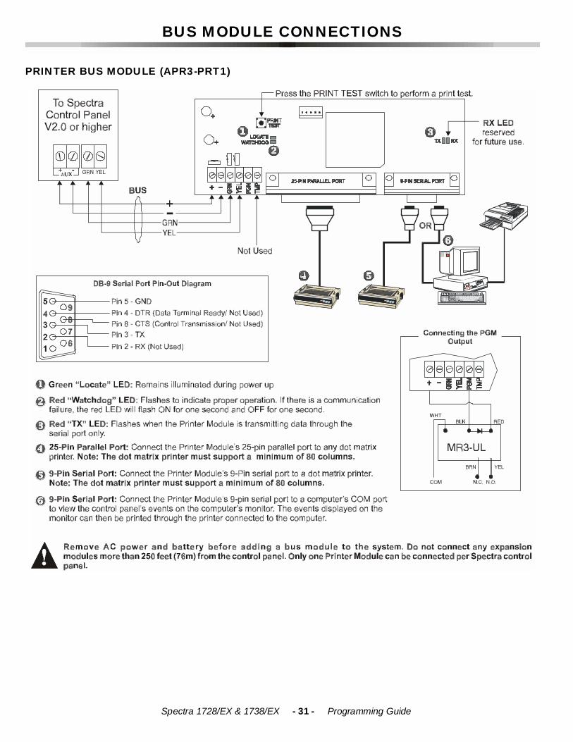
PRINTER BUS MODULE (APR3-PRT1)
Spectra 1728/EX & 1738/EX - 32 - Programming Guide
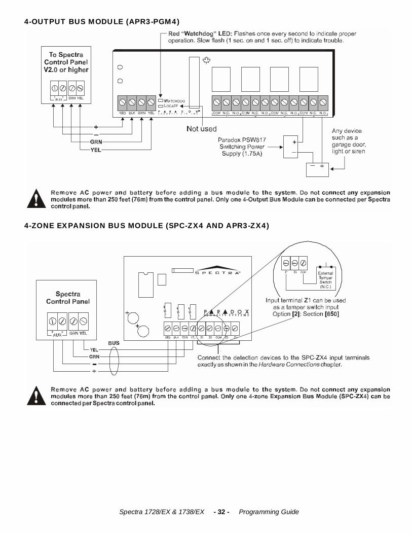
4-OUTPUT BUS MODULE (APR3-PGM4)
4-ZONE EXPANSION BUS MODULE (SPC-ZX4 AND APR3-ZX4)
Spectra 1728/EX & 1738/EX - 33 - Programming Guide
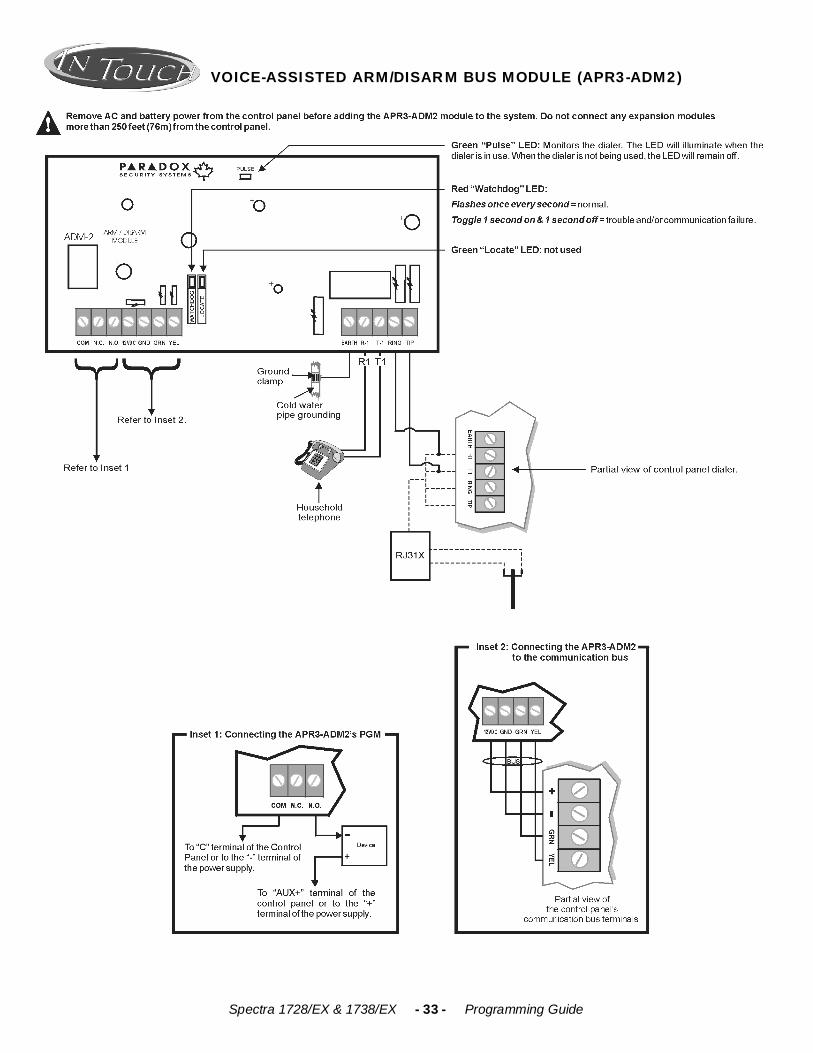
VOICE-ASSISTED ARM/DISARM BUS MODULE (APR3-ADM2)
Spectra 1728/EX & 1738/EX - 34 - Programming Guide
8-ZONE EXPANSION BUS MODULES (SPC-ZX8 AND APR3-ZX8)
900MHZ WIRELESS BUS MODULE (SPC-319)
Spectra 1728/EX & 1738/EX - 35 - Programming Guide
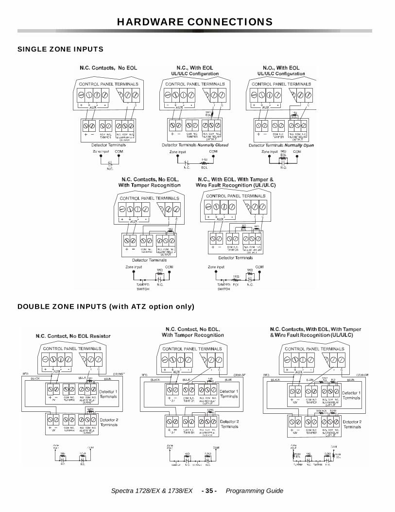
HARDWARE CONNECTIONS
SINGLE ZONE INPUTS
DOUBLE ZONE INPUTS (with ATZ option only)
Spectra 1728/EX & 1738/EX - 36 - Programming Guide
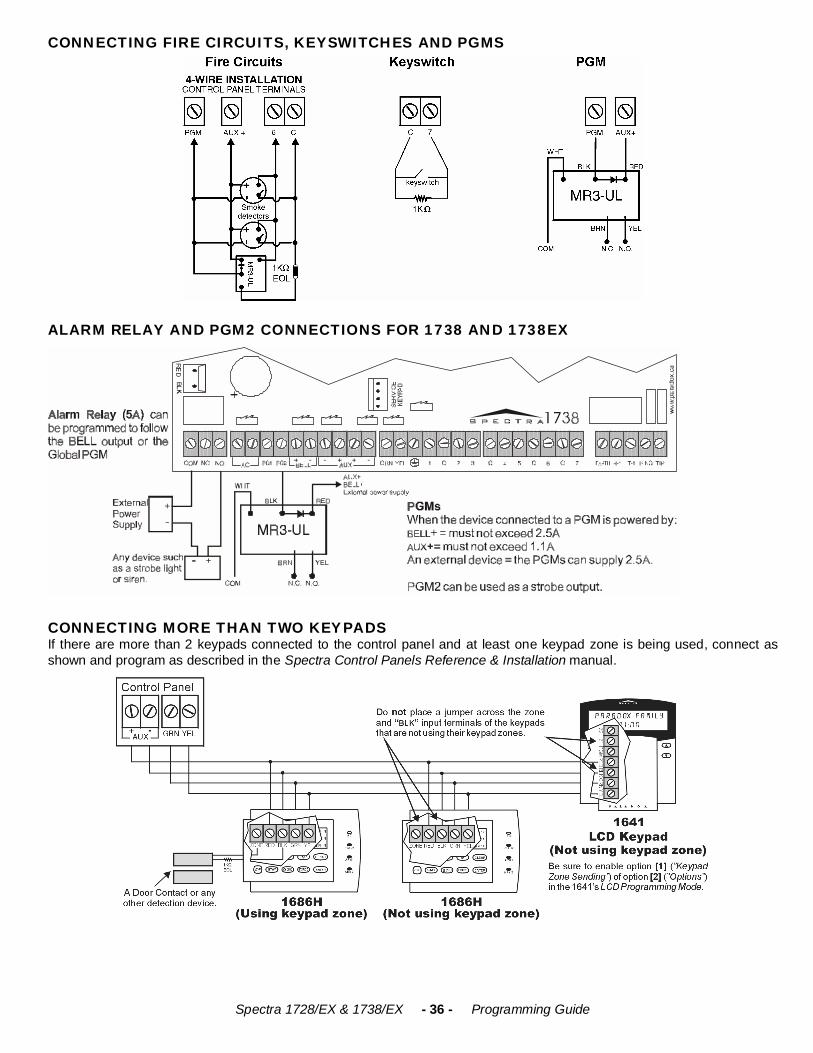
CONNECTING FIRE CIRCUITS, KEYSWITCHES AND PGMS
ALARM RELAY AND PGM2 CONNECTIONS FOR 1738 AND 1738EX
CONNECTING MORE THAN TWO KEYPADSIf there are more than 2 keypads connected to the control panel and at least one keypad zone is being used, connect asshown and program as described in the Spectra Control Panels Reference & Installation manual.
Spectra 1728/EX & 1738/EX - 37 - Programming Guide
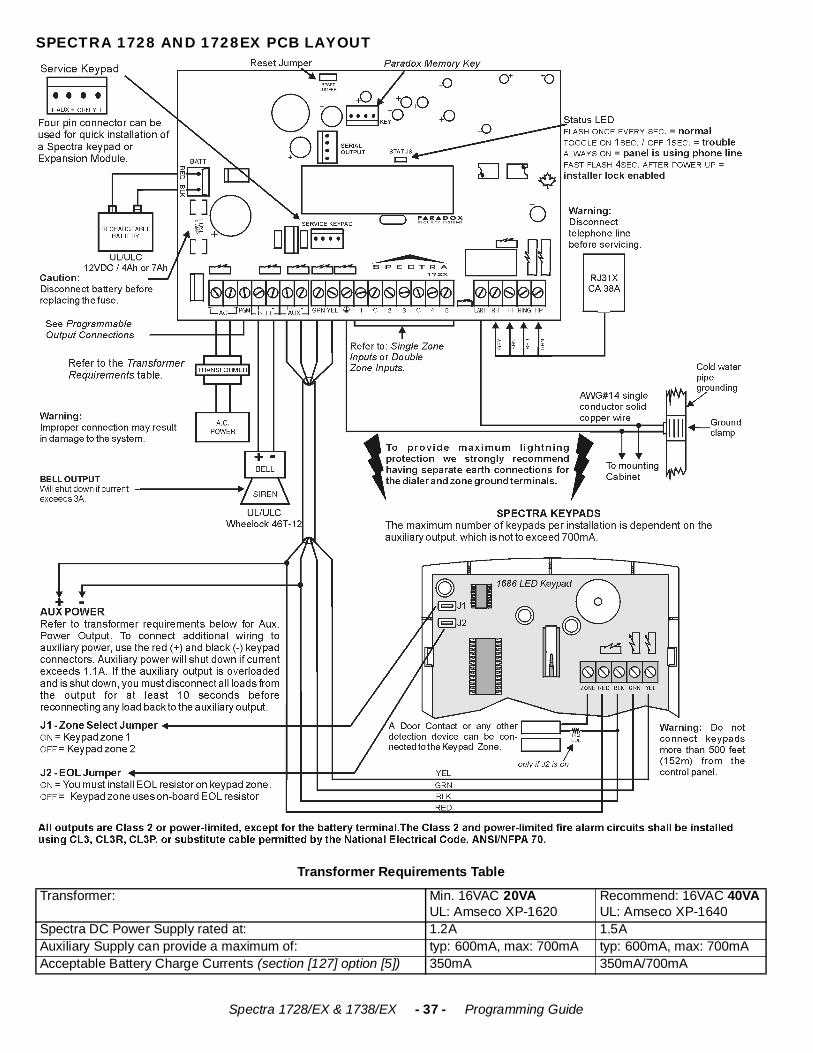
SPECTRA 1728 AND 1728EX PCB LAYOUT
Transformer Requirements Table
Transformer: Min. 16VAC 20VAUL: Amseco XP-1620
Recommend: 16VAC 40VAUL: Amseco XP-1640
Spectra DC Power Supply rated at: 1.2A 1.5AAuxiliary Supply can provide a maximum of: typ: 600mA, max: 700mA typ: 600mA, max: 700mAAcceptable Battery Charge Currents (section [127] option [5]) 350mA 350mA/700mA
Spectra 1728/EX & 1738/EX - 38 - Programming Guide
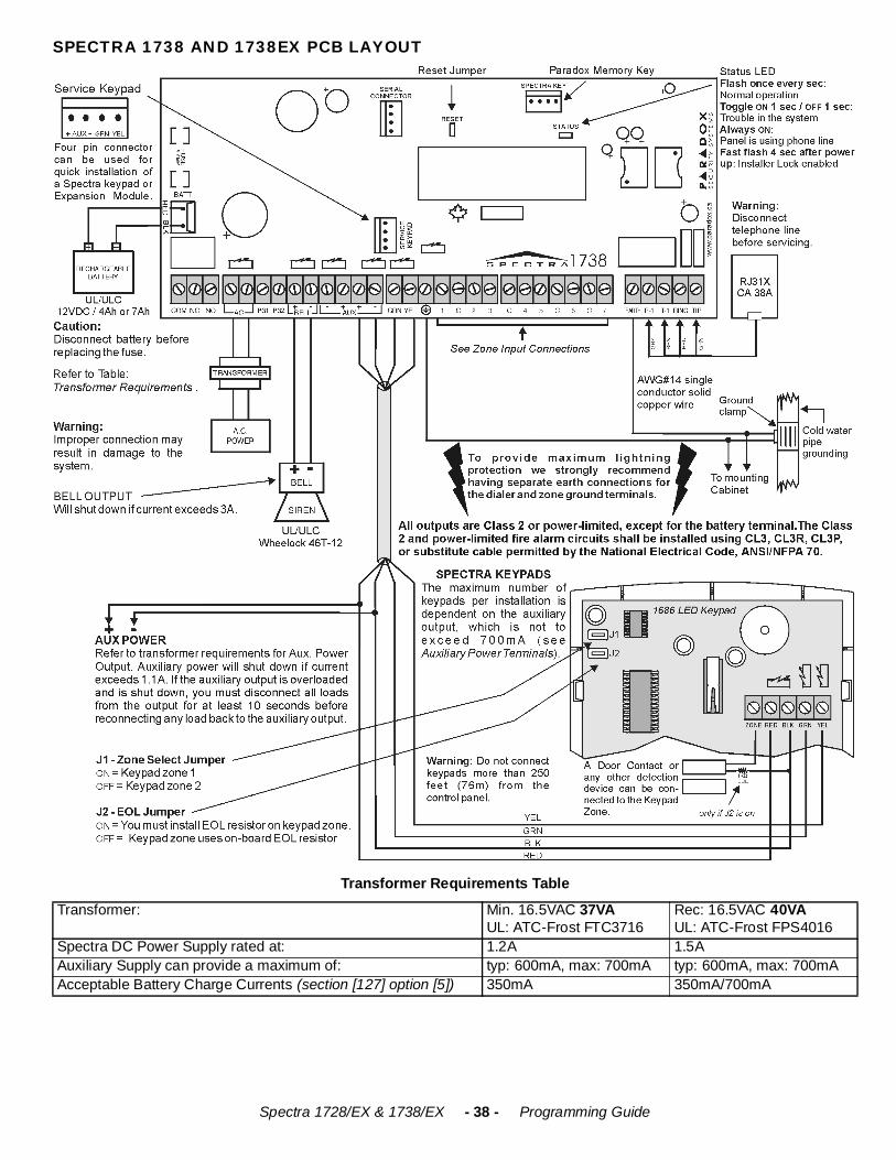
SPECTRA 1738 AND 1738EX PCB LAYOUT
Transformer Requirements Table
Transformer: Min. 16.5VAC 37VAUL: ATC-Frost FTC3716
Rec: 16.5VAC 40VAUL: ATC-Frost FPS4016
Spectra DC Power Supply rated at: 1.2A 1.5AAuxiliary Supply can provide a maximum of: typ: 600mA, max: 700mA typ: 600mA, max: 700mAAcceptable Battery Charge Currents (section [127] option [5]) 350mA 350mA/700mA

Spectra 1728/EX & 1738/EX - 39 - Programming Guide
NOTES

PRINTED IN CANADA 05/2001 17X8EP-02


![Software Version 2 - ssam.com Spectra 1728EX und 1728 PCB Darstellung“ auf S. 41 und „Spectra 1738EX und 1738 PCB Darstellung“ auf S. 42) Taste [2] OFF – EOL deaktiviert](https://img.pdfslide.us/doc/110x75/5abd76eb7f8b9ad8278bd975/software-version-2-ssamcom-spectra-1728ex-und-1728-pcb-darstellung-auf-s.jpg)