Embed Size (px)
Citation preview
DOCUMENT RESUME
ED 254 731 CE 041 007
TITLE Millwright Apprenticeship. Related Training Modules.17.1-1713 Hydraulics.
INSTITUTION Lane Community Coll., Eugene, Oreg.SPONS.AGENCY Oregon State Dept. of Education, Salem.PUB DATE [82]NOTE 127p.; For related documents, see CE 040 991-041 006.
Many of the same modules are duplicated in CE 040978.
PUB TYPE Guides - ClassiOom Use Materials (For Learner)(051)
EDRS PRICE MF01/PC06 Plus Postage.DESCRIPTORS *Apprenticeships; Behavioral Objectives; Energy
Occupations; *Hydraulics; Individualized Instruction;Job Skills; Learning Modules,; *Machine Tools;Maintenance; Postsecondary Education; *PowerTechnology; *Trade and Industrial Education
IDENTIFIERS *Millwrights; Power Plant Operators; Power Plants;Troubleshooting
ABSTRACTThis packet of 13 learning modules on hydraulics is 1
of 6 such packets developed for apprenticeship training formillwrights. Introductory materials are a completes listing of allavailable modules and a supplementary reference list. Each modulecontains some or all of these components: goal, performanceindicators, study guide (a check list of steps the student shouldcomplete), a vocabulary list, an introduction, information sheets,assignment sheet, job sheet, self-assessment, self-assessmentanswers, post-assessment, instructor post-assessment answers, and alist of supplementary references. Supplementary reference materialmay be provided. The 13 training modules cover levers; transmissionof force; symbols; basic systems; pumps; pressure relief valve;reservoirs; directional control valve; cylinders; forces, area, andpressure; conductors and connectors; troubleshooting; andmaintenance. (YLB)
************************************************************************ Reproductions supplied by EDRS are the best that can-be made ** from the original document. *
*****A*****************************************************************
APPRENTICESHIP
RELATEDTRAINING MODULES
7. - /7 3 )4064wics
U.S. DEPARTMENT OF EDUCATIONNATIONAL INSTITUTE OF EDUCATION
EDUCATIONAL RESOURCES INFORMATIONCENTER 1911CI
4/This document has been reproduced asreceived from the person or organizationoriginating it
Minor changes have been made In improvereproduction qualttV
Points of new rn opinions stated in this do, itment do not necessarily represent official NIE
position or policy
2
"PERMISSION TO REPRODUCE THISMATERIAL HAS BEEN GRANTED BY
ITO THE EDUCATIONAL RESOURCESINFORMATION CENTER tERIC)"
STATEMENT OF ASSURANCE
IT IS THE POLICY OF THE OREGON DEPARTMENT OF EDUCATION
THAT NO PERSON BE SUBJECTED TO DISCRIMINATION ON THE
BASIS OF RACE, NATIONAL ORIGIN, SEX, AGE, HANDICAP OR
MARITAL STATUS IN ANY PROGRAM, SERVICE OR ACTIVITY FOR
WHIC.i THE OREGON DEPARTMENT OF EDUCATION IS RESPONSIBLE.
THE DEPARTMENT WILL COMPLY WITH THE REQUIREMENTS OF STATE
AND FEDERAL LAW CONCERNING NON-DISCRIMINATION AND WILL
STRIVE BY ITS ACTIONS TO ENHANCE THE DIGNITY AND WORTH
OF ALL PERSONS.
STATEMENT OF DEVELOPMENT
THIS PROJECT WAS DEVELOPED AND PRODUCED UNDER A SUB-CONTRACT
FOP THE, OREGON DEPARTMENT OF EDUCATION BY LANE COMMUNITY
COLLEGE, APPRENTICESHIP DIVISION, EUGENE, OREGON, .1984.
LANE COMMUNITY COLLEGE IS AN AFFIRMATIVE ACTION/EQUAL
OPPORTUNITY INSTITUTION.
J
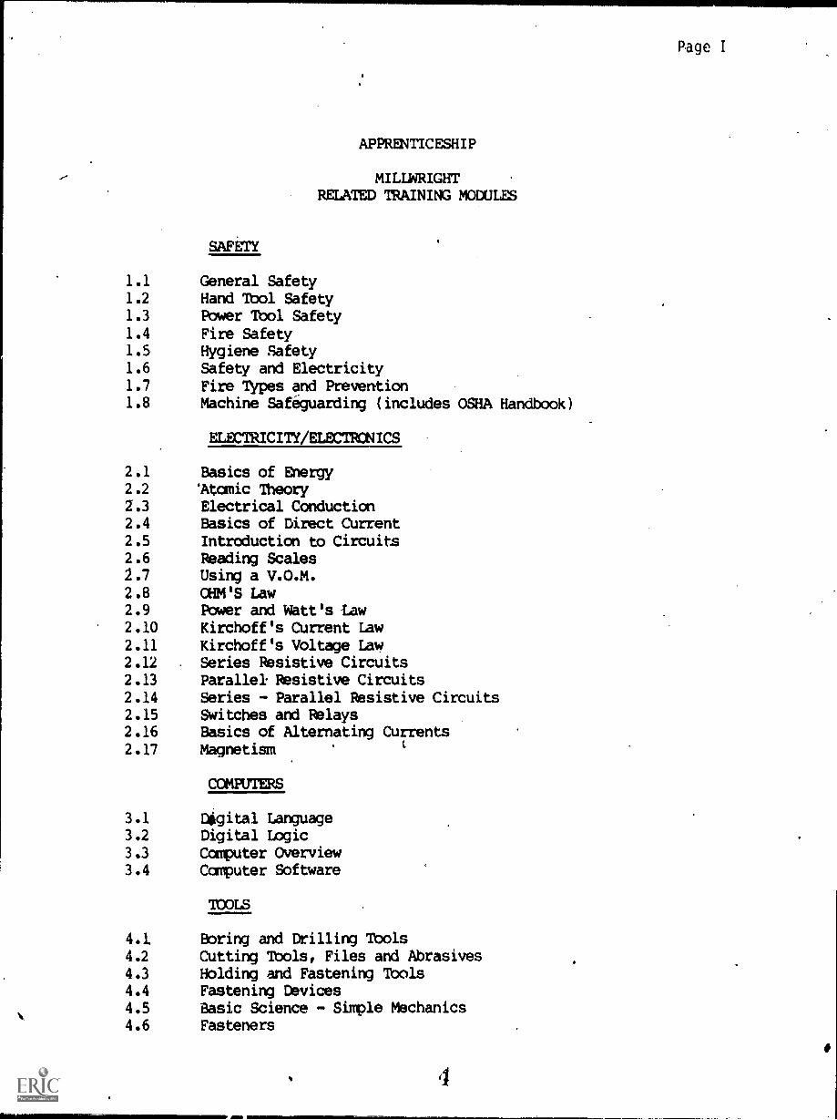
Page I
APPRENTICESHIP
MILLWRIGHTRELATED TRAINING MODULES
SAFETY
1.1 General Safety1.2 Hand Tool Safety1.3 Power Tool Safety1.4 Fire Safety1.5 Hygiene Safety1.6 Safety and Electricity1.7 Fire Types and Prevention1.8 Machine Safeguarding (includes OSHA Handbook)
ELECTRICITY/ELECTRONICS
2.1 Basics of Energy2.2 'Atomic Theory2.3 Electrical Conduction2.4 Basics of Direct Current2.5 Introduction to Circuits2.6 Reading Scales2.7 Using a V.O.M.2.8 OHM'S Law2.9 Power and Watt's taw2.10 Kirchoff's Current Law2.11 Kirchoff's Voltage Law2.12 Series Resistive Circuits2.13 Parallel Resistive Circuits2.14 Series - Parallel Resistive Circuits2.15 Switches and Relays2.16 Basics of Alternating Currents2.17 Magnetism
COMPUTERS
3.1 Digital Language3.2 Digital Logic3.3 Computer Overview3.4 Computer Software
TOOLS
4.1 Boring and Drilling Tools4.2 Cutting Tools, Files and Abrasives4.3 Holding and Fastening Tools4.4 Fastening Devices4.5 Basic Science - Simple Mechanics4.6 Fasteners
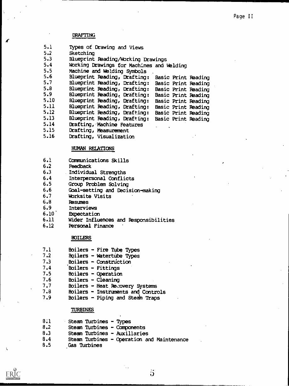
DRAFTING
S.I. Types of Drawing and Views5.2 Sketching5.3 Blueprint Reading/Working Drawings5.4 Wbrking Drawings for Machines and Welding5.5 Machine and Welding Symbols5.6 Blueprint Reading, Drafting: Basic Print5.7 Blueprint Reading, Drafting: Basic Print5.8 Blueprint Reading, Drafting: Basic Print5.9 Blueprint Reading, Crafting: Basic Print5.10 Blueprint Reading, Drafting: Basic Print5.11 Blueprint Reading, Drafting: Basic Print5.12 Blueprint Reading, Drafting: Basic Print5.13 Blueprint Reading, Crafting: Basic Print5.14 Erafting,'Machine Features5.15 Drafting, Measurement5.16 Drafting, Visualization
HUMAN RELATIONS
6.1 Communications Skills6.2 Feedback6.3 Individual Strengths6.4 Interpersonal Conflicts6.5 Group Problem Solving6.6 Goal-setting and Decision-making6.7 Wbrksite Visits6.8 Resumes6.9 Interviews6.10' Expectation6.11 Wider Influences and Responsibilities6.12 Personal Finance
7.1
7.2
7.3
7.47.5
7.6
7.77.8
7.9
BOILERS
Boilers -Boilers -
'Boilers -
Boilers -Boilers -Boilers -Boilers -Boilers -Boilers -
TURBINES
Fire Tube TypesWatertute TypesConstrdctionFittingsOperationCleaningHeat Re,:overy SystemsInstruments and ControlsPiping and Stead Traps
8:1 Steam Turbines8.2 Steam Ibrbines8.3 Steam TUrbines8.4 Steam TUrbines8.5 Gas Turbines
ReadingReadingReadingReadingReadingReadingReadingReading
- Types- Components- Auxiliaries- Operation and Maintenance
Page II
Page III
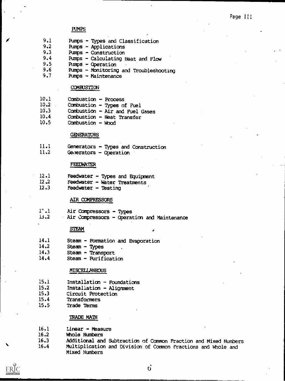
PUMPS
9.1 Pumps - Types and Classification9.2 Pumps - Applications9.3 Pumps - Construction9.4 Pumps - Calculating Heat and Flow9.5 Pumps - Operation9.6 Pumps - Monitoring and Troubleshooting9.7 Pumps - Maintenance
COMEUSTION
10.1 Combustion - Process10.2 . Combustion - Types of Fuel10.3 Combustion - Air and Fuel Gases10.4 Combustion - Heat Transfer10.5 Combustion Flood
GENERATCeS
11.1 Generators - Types and Construction11.2 Generators - Operation
FEEMATER
12.1 Feedwater Types and Equipment12.2 Feedwater - Water Treatments.12.3 Feedwater - Testing
AIR CCMPRESSORS
1".1 Air Conpressors - Types13.2 Air Ccmpressors - Operation and Maintenance
14.1 Steam - Formation and Evaporation14.2 Steam - Types14.3 Steam - Transport14.4 Steam - Purification
MISCELLANEOUS
15.1 Installation - Foundations15.2 Installation - Alignment15.3 Circuit Protection15.4 Transformers15.5 Trade Terms
TRADE MATH
16.1 Linear - Measure16.2 Whole Numbers16.3 Additional and Subtraction of Common Fraction and Mixed Numbers16.4 Multiplication and Division of Common Fractions and Whole and
Mixed Numbers
Page IV
16.516.6
16.7
16.816.916.10
16.11
17.1
17.2
17.3
17.4
17.5
17.6
17.7
17.8
17.917.10
17.1117.12
17.13
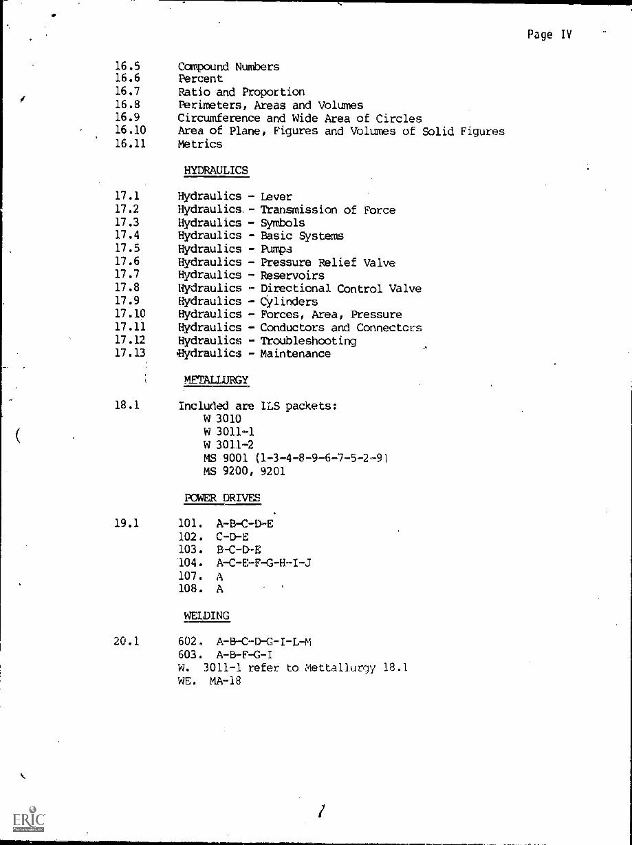
Compound NumbersPercentRatio and ProportionPerimeters, Areas and VolumesCircumference and Wide Area of CirclesArea of Plane, Figures and Volumes of Solid FiguresMetrics
HYDRAULICS
Hydraulics -Hydraulics, -
Hydraulics -Hydraulics -Hydraulics -Hydraulics -Hydraulics -Hydraulics -Hydraulics -Hydraulics -Hydraulics -Hydraulics -'Hydraulics -
LeverTransmission of ForceSymbolsBasic SystemsPumpsPressure Relief ValveReservoirsDirectional Control ValveCyl inders
Forces, Area, PressureConductors and ConnectcrsTroubleshootingMaintenance
METALLURGY
18.1 Included are 1LS packets:W 3010W 3011-1W 3011-2MS 9001 (1-3-4-8-9-6-7-5-2-9)MS 9200, 9201
ROWER DRIVES
19.1 101. A-B-C-D-E102. C-D-E103. B- C -D" -E
104. A-C-E-F-G-H-I-J107. A108. A
WELDING
20.1 602. A-B-C-D-G-I-L-M603. A-B-F-G-IW. 3011-1 refer to Mettallurgy 18.1WE. MA-18
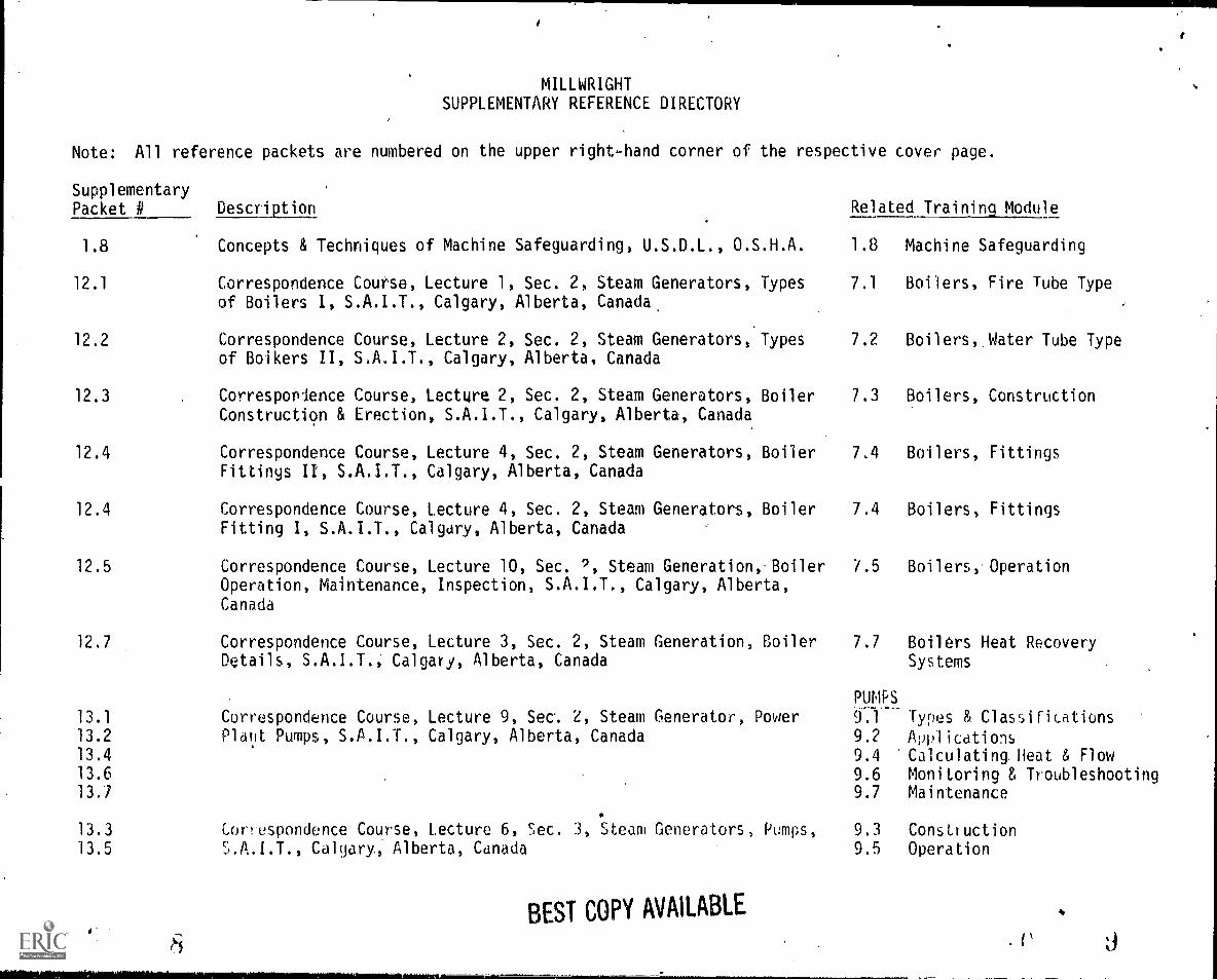
MILLWRIGHTSUPPLEMENTARY REFERENCE DIRECTORY
Note: All reference packets are numbered on the upper right-hand corner of the respective cover page.
SupplementaryPacket # Description Related Training Module
1.8 Concepts & Techniques of Machine Safeguarding, U.S.D.L., O.S.H.A. 1.8 Machine Safeguarding
12.1
12.2
Correspondence Course, Lecture 1, Sec. 2, Steam Generators, Typesof Boilers I, S.A.I.T., Calgary, Alberta, Canada,
Correspondence Course, Lecture 2, Sec. 2, Steam Generators, Typesof Boikers II, S.A.I.T., Calgary, Alberta, Canada
7.1
7.2
Boilers, Fire Tube Type
Boilers, Water Tube Type
12.3 Correspondence Course, Lecture 2, Sec. 2, Steam Generators, Boiler 7.3 Boilers, ConstructionConstruction & Erection, S.A.I.T., Calgary, Alberta, Canada
12.4 Correspondence Course, Lecture 4, Sec. 2, Steam Generators, Boiler 7,4 Boilers, FittingsFittings II, S.A.I.T., Calgary, Alberta, Canada
12.4 Correspondence Course, lecture 4, Sec. 2, Steam Generators, Boiler 7.4 Boilers, FittingsFitting I, S.A.I.T., Calgary, Alberta, Canada
12.5 Correspondence Course, Lecture 10, Sec. 9, Steam Generation,- Boiler /.5 Boilers, OperationOperation, Maintenance, Inspection, S.A.I.T., Calgary, Alberta,Canada
12.7 Correspondence Course, Lecture 3, Sec. 2, Steam Generation, Boiler 7.7 Boilers Heat RecoveryDetails, S.A.I.T., Calgary, Alberta, Canada Systems
PUMPS
13.1 Correspondence Course, Lecture 9, Sec, 2, Steam Generator, Power TY' Types & Classifications13.2 Plant Pumps, S.A.I.T., Calgary, Alberta, Canada 9.2 Applications13.4 9.4 Calculating. Heat & Flow13.6 9.6 Monitoring & Troubleshooting13.7 9.7 Maintenance
13.3 Correspondence Course, Lecture 6, Sec. 3, Steam Generators, Pumps, 9.3 Construction13.5 S.A.I.T., Calgary, Alberta, Canada 9.5 Operation
BEST COPY AVAILABLE
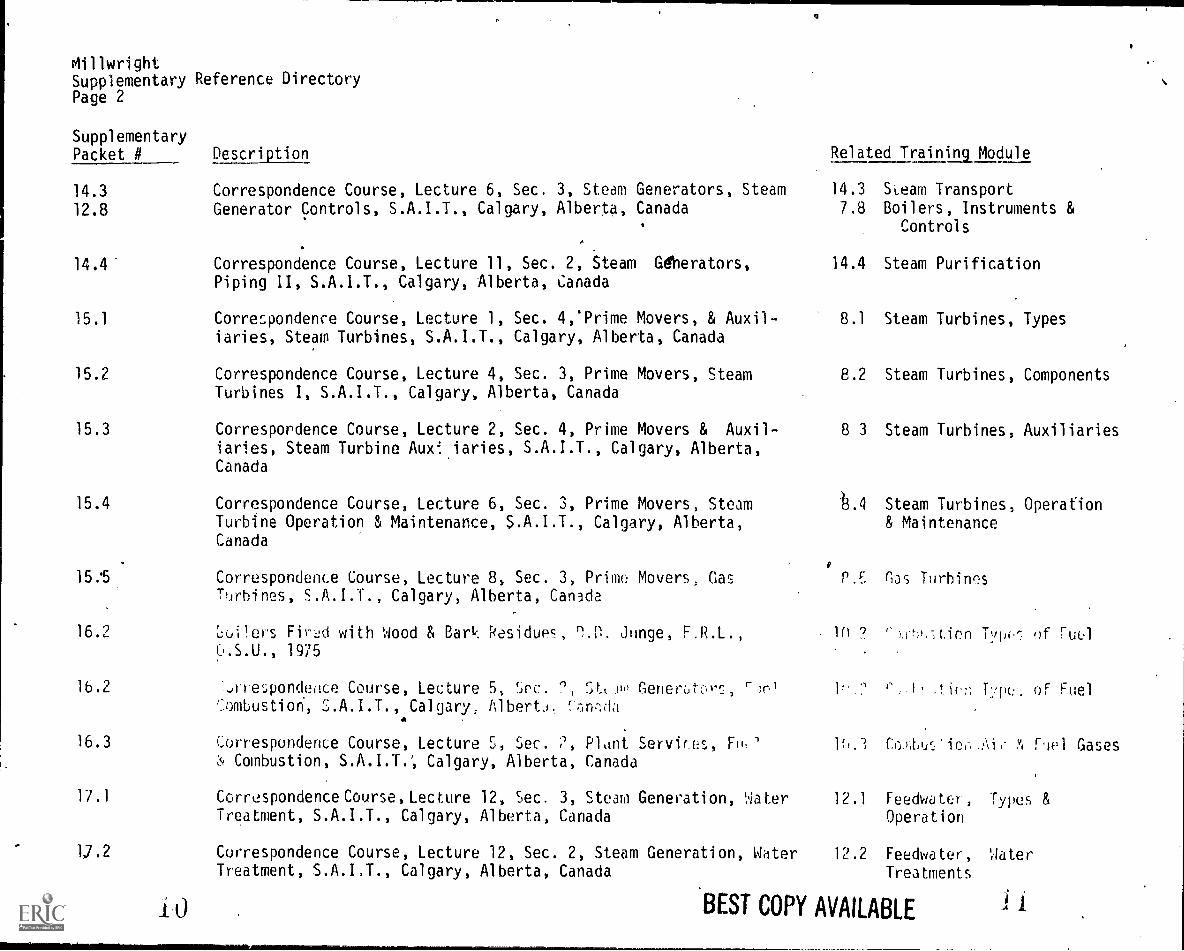
MillwrightSupplementary Reference DirectoryPage 2
SupplementaryPacket # Description
14.3 Correspondence Course, Lecture 6, Sec. 3, Steam Generators, Steam
12.8 Generator Controls, S.A.I.T., Calgary, Alberta, Canada
14.4- Correspondence Course, Lecture 11, Sec. 2, Steam Gdberators,Piping II, S.A.1.T., Calgary, Alberta, Canada
15.1 Correspondence Course, Lecture 1, Sec. 4:Prime Movers, & Auxil-iaries, Steam Turbines, S.A.I.T., Calgary, Alberta, Canada
15.2 Correspondence Course, Lecture 4, Sec. 3, Prime Movers, SteamTurbines I, S.A.I.T., Calgary, Alberta, Canada
15.3 Correspordence Course, Lecture 2, Sec. 4, Prime Movers & Auxil-iaries, Steam Turbine Aux'.iaries, S.A.I.T., Calgary, Alberta,Canada
15.4 Correspondence Course, Lecture 6, Sec. 3, Prime Movers, SteamTurbine Operation & Maintenance, S.A.I.T., Calgary, Alberta,Canada
15..5 Correspondence Course, Lecture 8, Sec. 3, Prime Movers, GasTurbines, S.A.I.T., Calgary, Alberta, Canada
16.2 roomers Fir:A with Wood & Bark Residues, Junge, F.R.L.,1975
16.2 -a.re4ond.eoce Course, Lecture 5, (:)vc. ?, Stcilo Generbtc,r, r)Thmbustion, S.A.I.T., Calgary, Alberta.
16.3 correspondence Course, Lecture S, Sec. 2, Plant Services, F1,'Combustion, Calgary, Alberta, Canada
17.1 Correspondence Course, Lecture 12, Sec. 3, Steam Generation, WaterTreatment, S.A.I.T., Calgary, Alberta, Canada
12.2 Correspondence Course, Lecture 12, Sec. 2, Steam Generation, WaterTreatment, S.A.I.T., Calgary, Alberta, Canada
Related Training Module
14.3 Seam Transport7.8 Boilers, Instruments &
Controls
14.4 Steam Purification
8.1 Steam Turbines, Types
8.2 Steam Turbines, Components
8 3 Steam Turbines, Auxiliaries
13.4 Steam Turbines, Operation& Maintenance
O
(',as Turhins
111 9 f'.):1-tien 1./w: of ruel
1 ' Typc:. of Fuel
lh.3 CrAtiurZiciAif- roe l Gases
12.1 Feedwater, Types &Operation
12.2 Feedwater, WaterTreatments
BEST COPY AVAILABLE
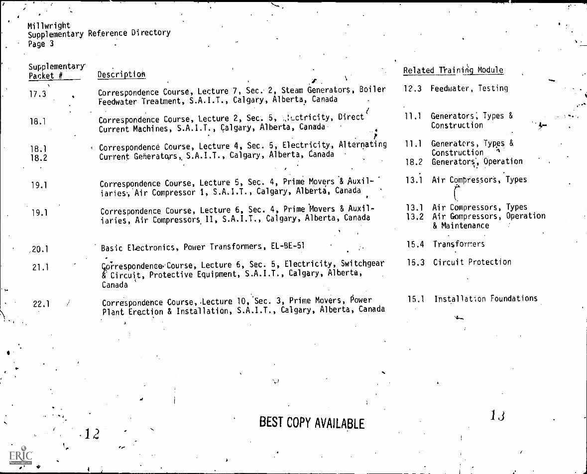
MillwrightSupplementary Reference Directory
Page 3
SupplementaryPacket # DescrtplicAl
Correspondence Course, Lecture 7, Set; 2, Steam Generators, Boiler
Feedwater Treatment, S.A.I.T., Calgary, Alberta, Canada17.3
18.1
18.1
18.2
19.1
19.1
Correspondence Course, Lecture 2, Sec. 5, ..,!Lctricity, Direct
Current Machines, S.A.I.T., Calgary, Alberta, Canada 4
Correspondence Course, Lecture 4, Sec. 5, Electricity., Alternating
Current Geheratoys, S.A.I.T., Calgary, Alberta, Canada
Correspondence Course, Lecture 5, Sec. 4, Prime Movers & Auxil-
iaries, Air Compressor 1, S.A.I.T., Calgary, Alberta, Canada
Correspondence Course, Lecture 6, Sec. 4, Prime Movers & Auxil-
iaries, Air Compressors, II, S.A.I.T., Calgary, Alberta, Canada
20.1 Basic Electronics, Power Transformers, EL-BE-51
21.1 co*rrespondence,Course, Lecture 6, Sec. 5, Electricity, Switchgear
&Circuit, Protective Equipment, S.A.I.T., Calgary, Alberta,
Canada
22.1 i Correspondence Course,lecture 10, Sec. 3, Prime Movers, dower
Plant Erection & Installation, S.A.I.T., Calgary, Alberta, Canada
.
'
BEST COPY AVAILABLE
Related nainifig Module
12.3 Feedwater, Testing
11.1 Generators; Types &
Construction
11.1 Generators, Types &
Construction fi
18.2 Generators Operation
13.1 Air Compressors, Types
13.1 Air Compressors, Types13.2 Air Gompressors, Operation
& Maintenance
15.4 Transformers
15.3 Circuit Protection
15.1 Installation Foundations.
13
RECOMMENDATIONS FOR USING TRAINING MODULES'
The following pages list modules and their corresponding numbers for this
particular apprenticeship trade. As related training classroom hours
vary for different reasons throughout the state, we recommend that
the individual apprenticeship committ:es divide the total packets to
fit their individual class schedules.
There are over 130 modules available. Apprentices can complete the
whole set by the end of their indentured apprenticeships. Some
apprentices may already haveknowledge and skills that are covered
in particular modules. In those cases, perhaps credit could be
granted for those subjects, allowing apprentcies to advance to the
remaining modules.
We suggest the the apprenticeship instructors assign the modules in
numerical order to make this learning tool most effective.
1,1
'1
SUPPLEMENTARY INFORMATION
ON CASSETTE TAPES
Tape 1: Fire Tube Bonet - Water Tube Boilersand Boiler Manholes and Safety Precautions
Tape 2: Boiler Fittings, Valves, Injectors,Pumps and Steam Traps
Tape 3: Combustion, Boiler Care and Heat Transferand Feed Water Types
Tape 4: Boiler Safety and Steam Turbines
NOTE: The above cassettereference materialindicated, and not
tapes are intended as additionalfor the respective modules, asdesignated as a required assignment.
Modules 18.1, 19.1, and 20.1 have been omitted because they containdated materials.
41/
MCiLIMCMAL LEA-IrlirK W)M1.1
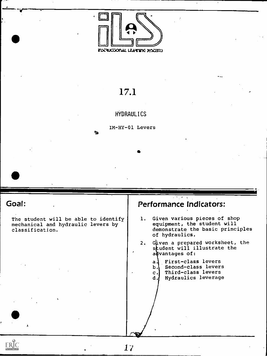
17.1
HYDRAULICS
IM-HY-01 Levers
The student will be able to identifymechanical and hydraulic levers byclassification.
A
Performance Indicators:
1. Given various pieces of shopequipment, the student willdemonstrate the basic principlesof hydraulics.
2. G ven a prepared worksheet, thes udent will illustrate thea vantages of:
First-class leversb. Second-class leversc. Third-class leversd. Hydraulics leverage
1/
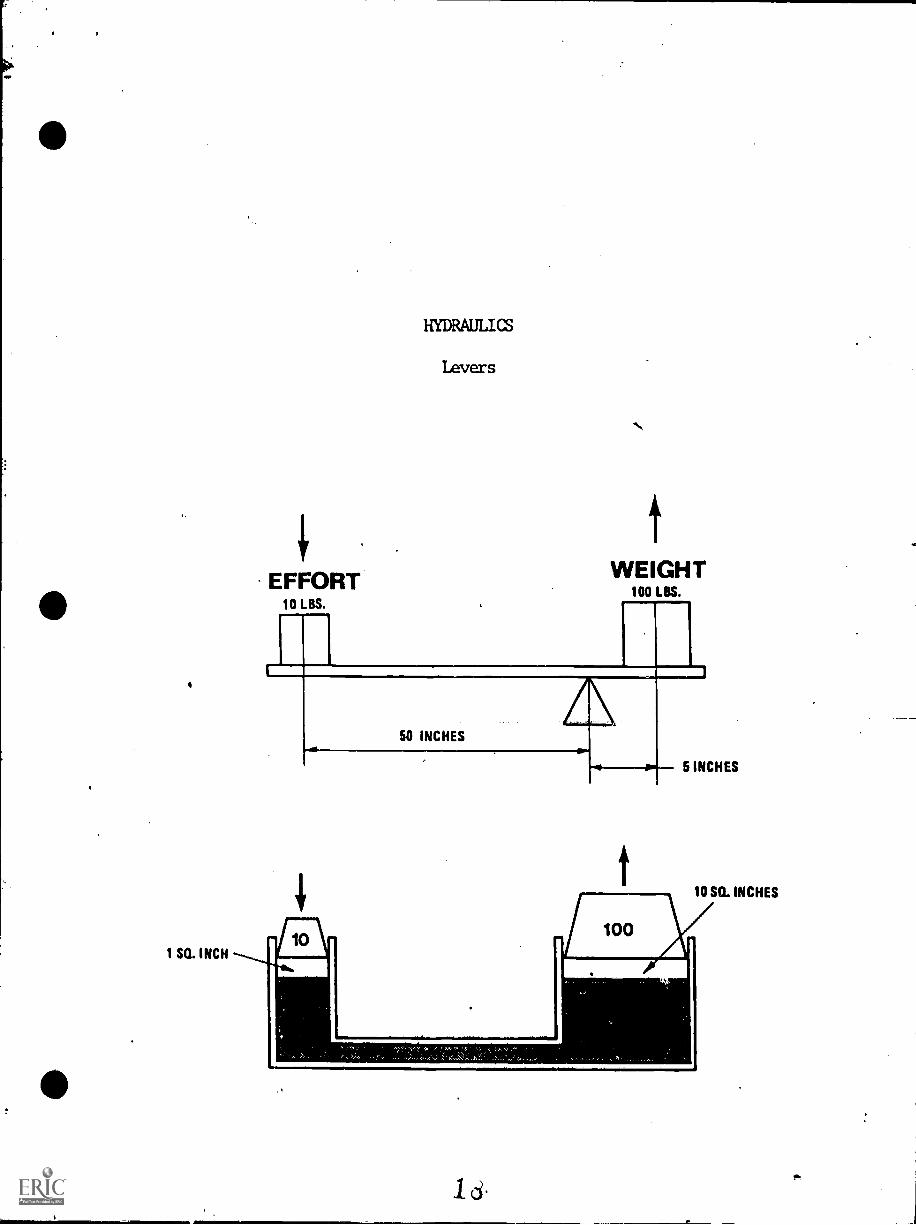
1 SQ. INCH
HYDRAULICS
Levers
EFFORT10 LBS.
WEIGHT100 LBS.
50 INCHES
100
5 INCHES
10 50. INCHES
INSTRUCTIONAL LEARNING SYSTEMS
Information
.41=u..
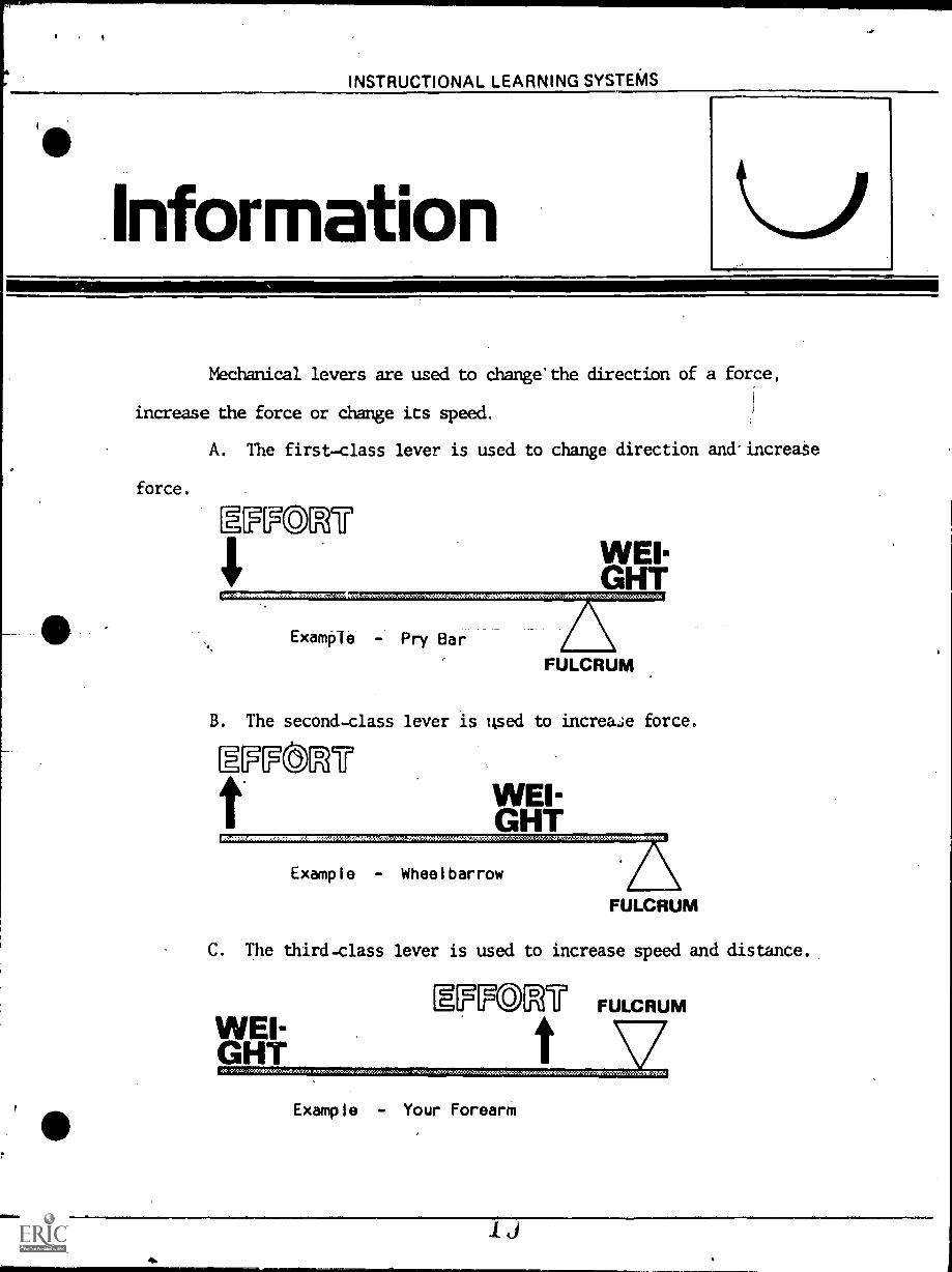
Mechanical levers are used to change'the direction of a force,
increase the force or change its speed.
force.
A. The first-class lever is used to change direction and.increase
WEIGHT
Example - Pry Bar
FULCRUM
B. The second-class lever is used to increase force.
WEI-GHT
Example - Wheelbarrow
FULCRUM
C. The third-class lever is used to increase speed and distance.
mcgomr FULCRUM
Example - Your Forearm
INSTRUCTIONAL LEARNING SYSTEMS
Job Sheet
-4.-
WORKSHEET
1. Complete the following table listing a; least one lever
of each class that you have observed.
Lever Observed Class of Lever
1.
2.
3.
4.
5.
6.
7.
4
INSTRUCTIONAL LEARNING SYSTEMS
Assignment
LEARNING ACTIVITIES
1. Use a triangular block of wood, a meter or yard stick and
weights to demonstraLe levers of the first, second and third class.
2. Examine shop equipment and hand tools to determine the
type of lever(s) involved in each.
INSTRUCTIONAL LEARNING SYSTEMS
SElfAssessment
Iowa
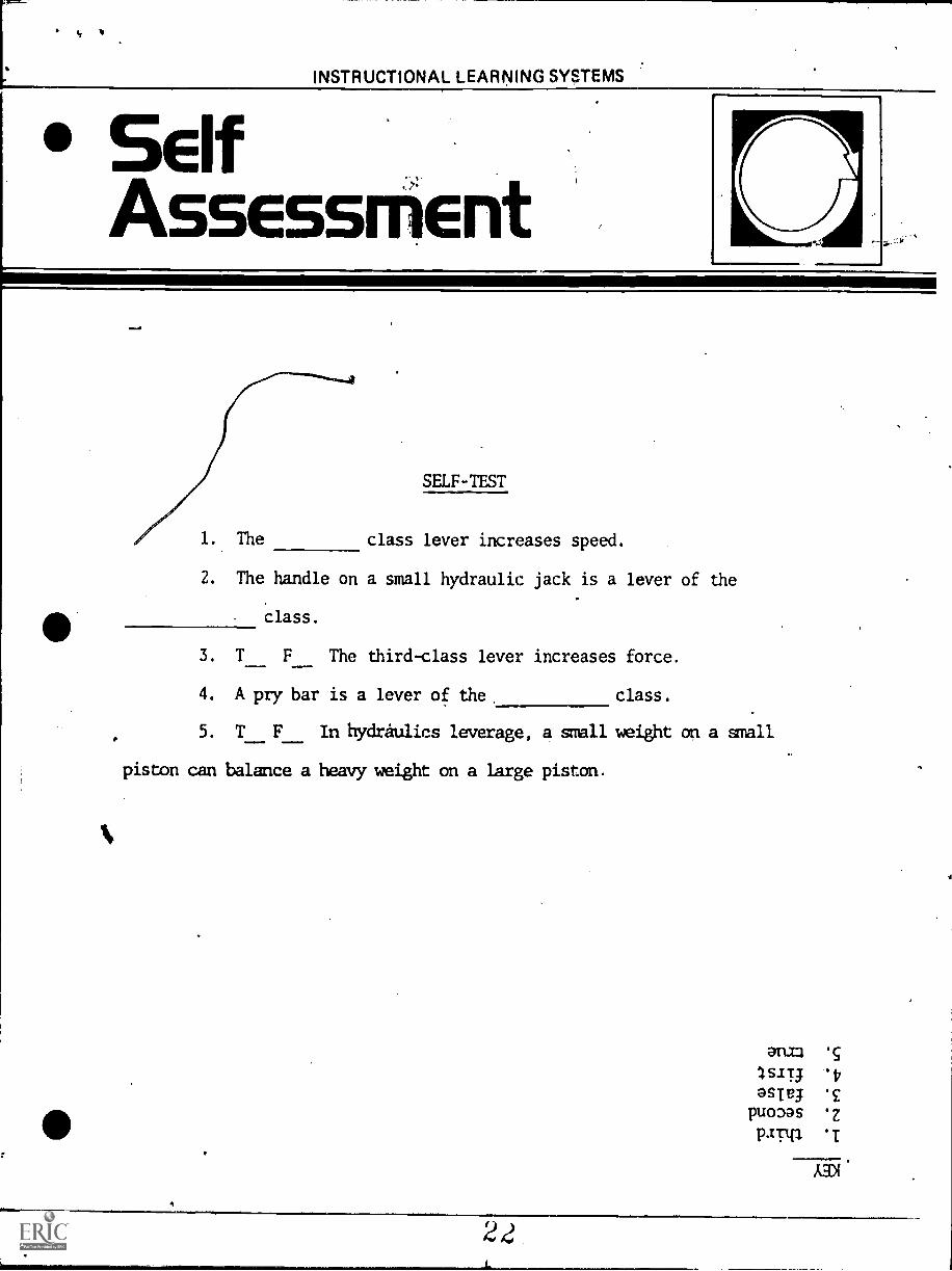
SELF-TEST
1. The class lever increases speed.
2. The handle on a small hydraulic jack is a lever of the
class.
3. T F The third-class lever increases force.
4. A pry bar is a lever of the. class.
5. T F In hydraulics leverage, a small weight on a small
piston can balance a heavy weight on a large piston.
ec
s-IT; 'V
asTe; *£puoaas ez
PTIP 'I
22
INSTRUCTIONAL LEARNING SYSTEMS
PostAssEssmEnt
POST-TEST
1. Draw the three classes of levers and indicate the advan-
tage of each.
1.
2.
3.
Lever.Class Advantages
41111011
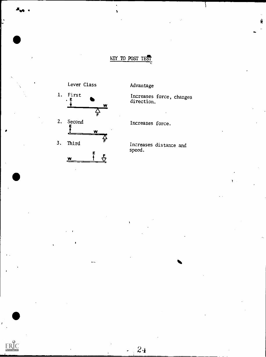
KEY TO POST TEgt
Lever Class Advantage
1. First Increases force, changesE 4116 direction.
F
2. Second
3. Third
w
W
F'7!
E
T
Increases force.
Increases distance andspeed.
.1,010111111,
4
J
ru..--AumonALLiA-Tmc
17.2
HYDRAULICS
IM-HY-02
Transmission of Forces by Use of Liquidsin Confinement Under Pressurt
it
Goal:The student will be able todemonstrate how force ismultiplied through a confinedfluid.
Performance Indicators:1. Given a prepared worksheet, the
student will:
a. Illustrate the prindiples ofthe transmission of forcethrough a liquid.
b. List the basic principles ofhydraulics.
2. Given the dimensions of a pistonand cylinder, the student willcompute the area.
26
ImS
C.
r
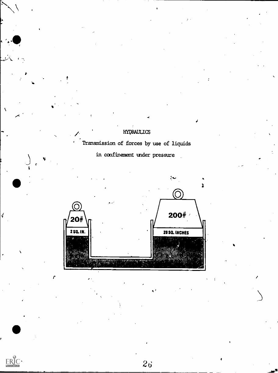
HYDRAULICS
' Transmission of forces by use of liquids
in confinement under pressure
INSTRUCTIONAL LEARNING SYSTEMS
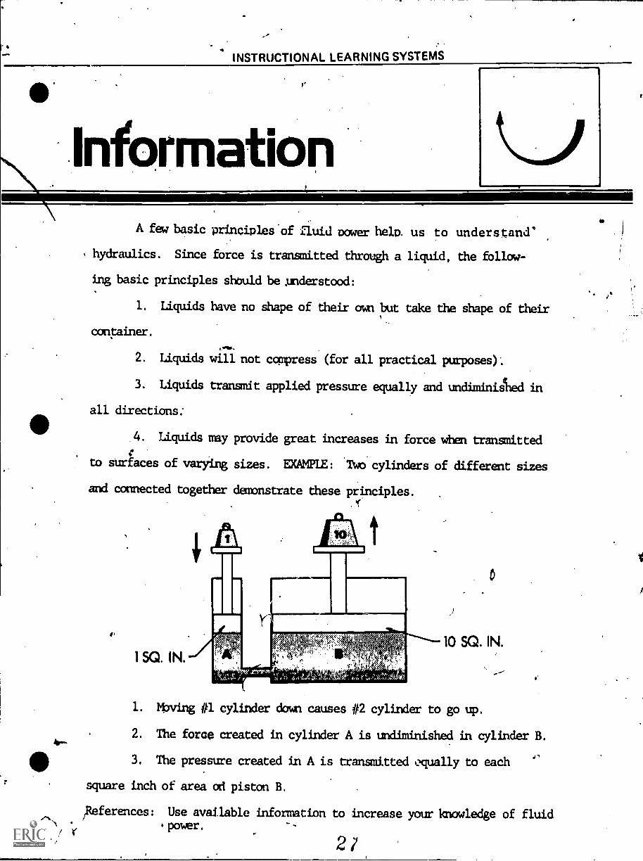
nformationA few basic princibles'of fluid bower help, us to unde.rstand°
hydraulics. Since force is transmitted through a liquid, the follow-
ing basic principles should be understood:
1. Liquids have no shape of their own but take the shape of their
container.
2. Liquids will not compress (for all practical purposes).
3. Liquids transmit applied pressure equally and undhninilhed in
all directions..
4. Liquids may provide great increases in force when transnitted
tor
to surfaces of varying sizes. EXAMPLE: Two cylinders of different sizes
and connected together demonstrate these principles. .
10 SQ. IN.
off
1. Moving #1 cylinder dam causes #2 cylinder to go up.
2. The force created in cylinder A is undiminished in cylinder B.
3. The pressure created in A is transmitted equally to each
square inch of area on piston B.
iitogerences: Use available information to increase your knowledge of fluidpower.
2?
INSTRUCTIONAL LEAR ING SYSTEMS
Assignment
LEARNING ACTIVITIES
1. Use a small hydraulic jack to answer the following:
A. The handle is connected to the (smaller, larger) cylinder.
B. The force put on the handle is transmitted by a
C. Does the small piston move (a shorter distance,the-same
distance, a greater distance) than the larger piston?
D. How far must you move the smiler piston to move the larger'
piston one inch?
E. If the area of the smaller piston is increased to 2 sq. in.,
the force increased to 6 pounds, ha; much load could be
supported by the large piton?
so.
2d
INSTRUCTIONAL LEARNING SYSTEMS
J b Sheet
1. In the space above sketch a simple hydraulic system showing.%
the transmission of force.
2. Color the area red where hydraulic fluid under pressure is
111
2
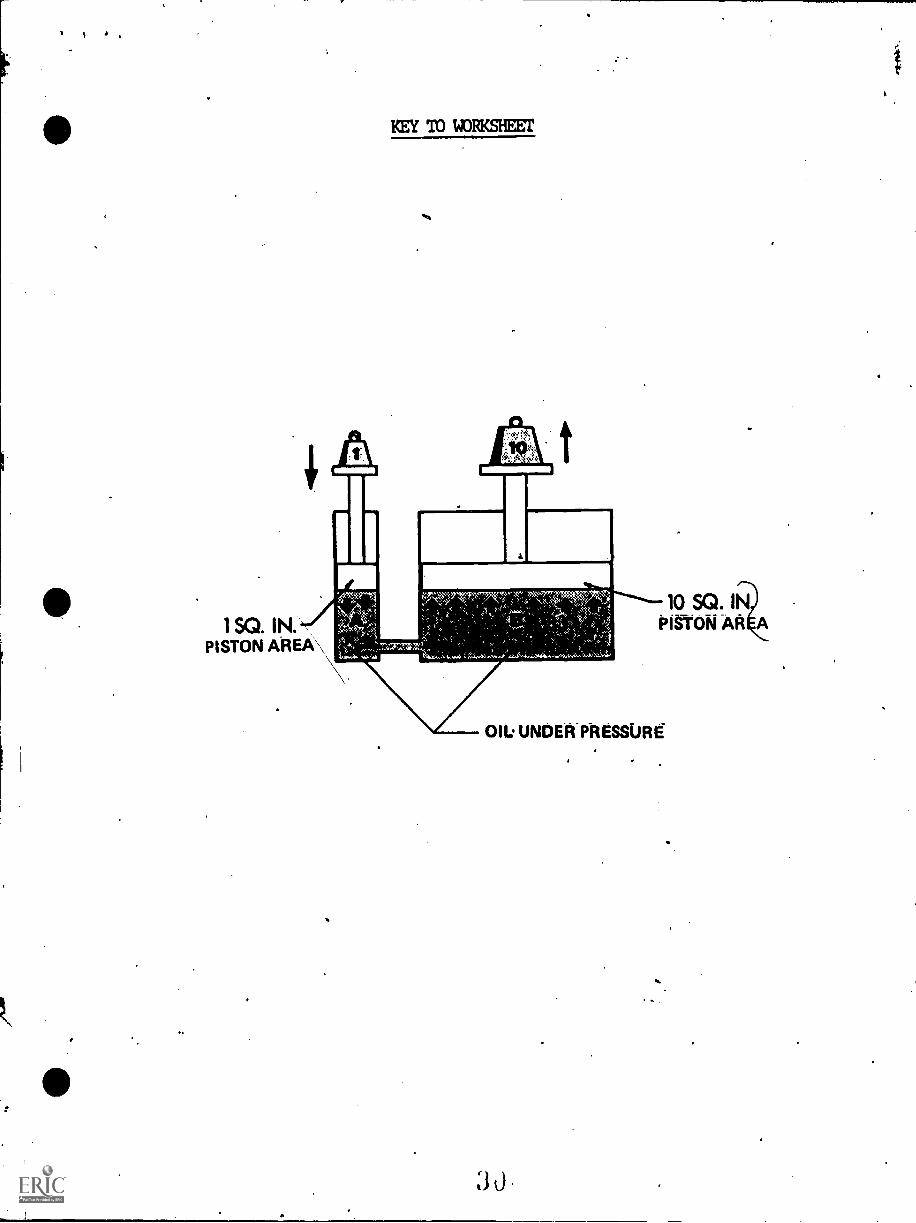
1 SQ. IN.PISTON AREA\
KEY 'TO 14)11KSIEET
10.
10 SQ. INPigi-oN AREA
OIL' UNDER PRESSURE.
INSTRUCTIONAL LEARNING SYSTEMS
SelfAssessment
SELF-TEST
1. T F Fluid will not transfer all the force from one
place to another.
2. T ^ F Hydraulic ce cannot be transmitted over great
distances.
3. T F Liquids can be ccxnpressed.
4./1 T F Because liquids have no shape of their own they can
be used to transmit force against odd-shaped surfaces.
5. T -F ale pound can be used to lift ten pounds hydraulically.
anaj, ganal 47
°siva 'Eastv.1asp,
*Z[
31
.4
INSTRUCTIONAL LEARNING SYSTEMS .
PostAssessment
i SQ. IN.
POST-TEST
10 SQ. IN.
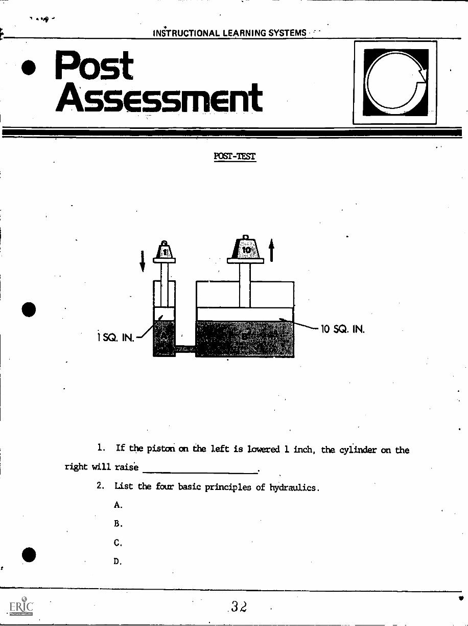
1. If the piston on the left is lowered 1 inch, the cylinder on the
right will raise
2. List the four basic principles of hydraulics.
A.
B.
C.
D.
32
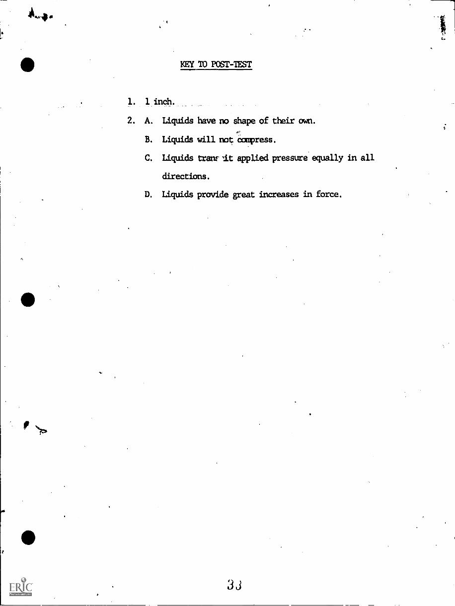
KEY 10 POST-TEST
1. 1 inch.
2. A. Liquids have no shape of their own.
--B. Liquids will not =press.
C. Liquids tram- It applied pressure equally in all
directions.
D. Liquids provide great increases in force.
33
WINCIUMALLEA-11111C M0.11.5
17.3
HYDRAULICS
IM-HY-03 Symbols
Goal:
The student will be able todistinguish between the varioussymbols used in fluid power andtheir purpose in drawings ofhydraulic diagrams.
Performance Indicators:
1. Given a prepared worksheet, thestudent will use graphicalsymbols to draw a basic fluidpower circuit.
2. Given a training bench and thenecessary system components, thestudent will assemble the systemand operate it.
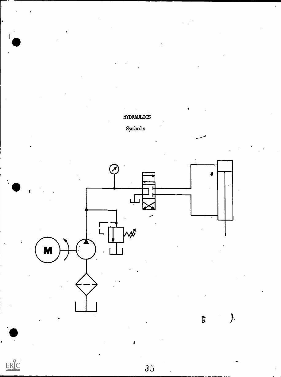
HYDRAULICS
Symbols
INSTRUCTIONAL LEARNING SYSTEMS
InformationAmerican Uational Standard Institute graphical study for
fluid power diagrams (ansi y 32.10).
Type of symbols used in drawing circuit diagrams for fluid power"41k.
systems are pictorial, cutaway and graphic.
Pictorial symbols are very useful for showing the interconnection
of components. They are difficult to standardize from a functional basis.
Cutaway symbols emphasize construction. These symbols are complex
to draw and the functions are not readily apparent.
Graphic symbols eaphasize the function and methods of component
operation. ...These symbols are simple to draw. Ccopcnent functions and
methods of operation are obvious. Graphical symbols are capable of
crossing language barriers and can pranot a universal understanding of
fluid power systems.
Elementary forms of symbols fare:
A. Circles.
B. Squares.
C. Triangles.
D. Rectangles.
E. Arcs.
F. Arrows.
G. Straight lines.
H. Dots.
I. Crosses.
a
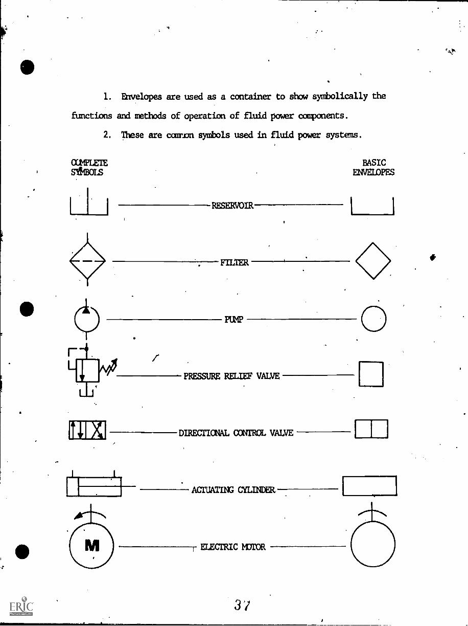
1. Envelopes are used as a container to show symbolically the
functions and methods of operation of fluid power components.
2. These are common symbols used in fluid power systems.
0:11PLEIE
Sli4BOLS
RESERVOIR
FILTER
7
PUMP
BASICENVEIDPES
1
PRESSURE RELIEF VALVE
DIRECTIONAL =TOOL VALVE
ACTUATING CYLINDER.
ELECTRIC mfroR
011
LL
I
INSTRUCTIONAL LEARNING SYSTEMS
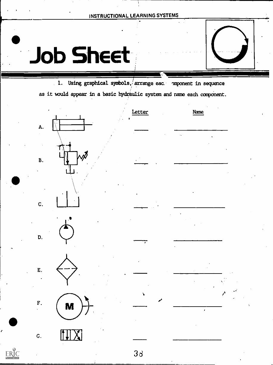
Job Sheet1. Using graphical symbols,:larrange eac. imponent in sequence
as it would appear in a basic hydrulic system and name each component.
C
D.
F
G.
Letter
101011
36
.111.171.1.111.
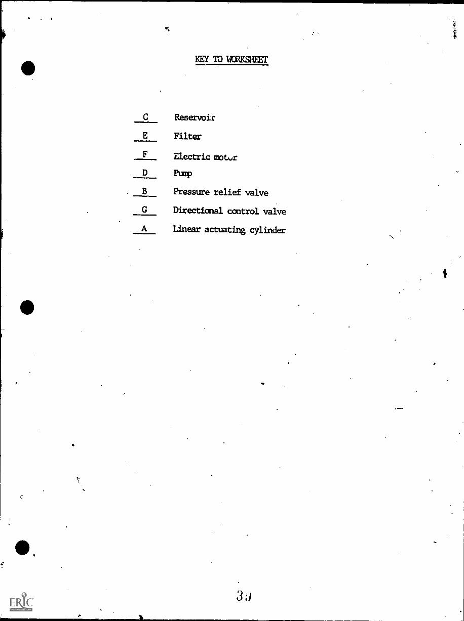
KEY W WORKSHEET
C Reservoir
E Filter
F Electric notvr
B
Pump
Pressure relief valve
G Directional control valve
A Linear actuating cylinder
3J
Self.Assessment
INSTRUCTIONAL LEARNING SYSTEMS , .
lt,
I
CCMPLE1ESYMBOLS
L
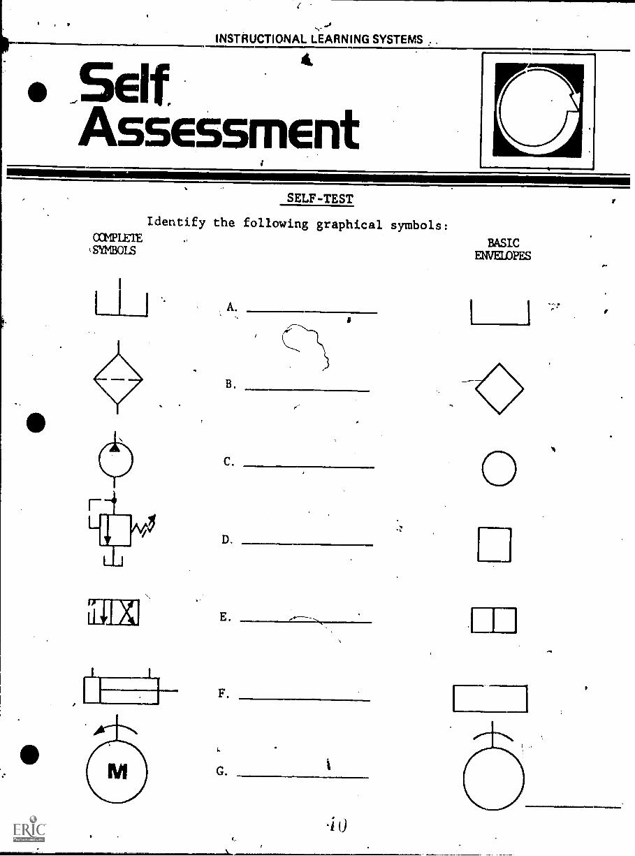
SELF-TEST
Identify the following graphical symbols:
B.
D.
E
F.
G.
BASICENVEIAPES
O
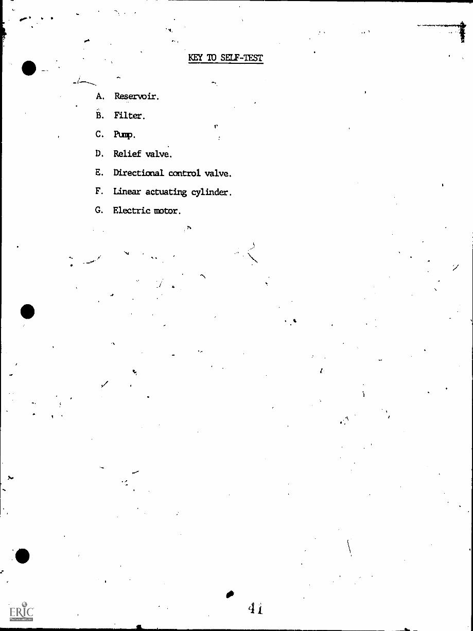
KEY 10 SELF-TEST
A. Reservoir.
B. Filter.Th
C Punp.
D. Relief valve.
E. Directional control valve.
F. Linear actuating cylinder.
G. Electric raptor.
-
alo
cit
od
INSTRUCTIONAL LEARNING SYSTEMS
PostAssessment
0
POSTTESI'
1. Draw Bach envelope in proper sequence in the system.
.0
4
EINCIUMOCIALL LEA-111111C
17.4
HYDRAULICS
IM-HY-04
Basic Symbols
Goal:The student will be able to identifyeach component in a fluid powersystem and describe its function.
Performance Indicators:1. Given prepared worksheets, the
student will illustrate theoperation of a basic hydraulicsystem.
2. Given the following hydraulicsystem components, the 'studentwill correctly identify them andtell the function of each in thesystem.
a.b.c.d.e.
f.
g.h.
ReservoirFilterPumpPressure relief valveDirectional control valveActuatorsPrime moverConductors
44
4
GEAR PUMP
J
HYDRAULICS
Basic Systan
LRELIEFVALVE
NAM
IL
DIRECTIONALCONTROLVALVE
0
am111110 CYLINDER
r.
IIMMERN=WW.OPINSTRUCTIONAL LEARNING SYSTEMS
InforenationThere are three basic methods of controlling energy; mechanical,
electrical and fluid power. Most often they are combined for the most
effective usage. Both mechanical and fluid power transmissions have
been used for thousands of years and these past two hundred years have
seen man harness and use electricity.
Fluid power is by far the most effective means of power trans-
mission. The purpose of a hydraulic system is to transfer energy from
r
one place to another. With hydraulic systems, large forces can be readily
applied and easily controlled. Compared to a mechanical system CT electri-
cal system, a hydraulic system is simple since components can be located
with greater flexibility. A hydraulic system is effecient and economical
to operate because power and friction losses are relatively small and wear
on wiring parts is greatly reduced. In addition, Large forces can be
simply controlled by much smaller forces throughout an infinite range of
speeds.
All fluids and liquids have certain characteristics. The principles
of hydraulics are based on the following facts:
1. A fluid has no definite shape of its own but conforms to the
shape of its container.
2. A fluid will 'always take the path of least resistance.
3. A liquid unlike a gas is nearly incompressible while a gas
is highly compressible. An oil can only be compressed to 1.2 percent
of its total volume at 3000 psi.
46'
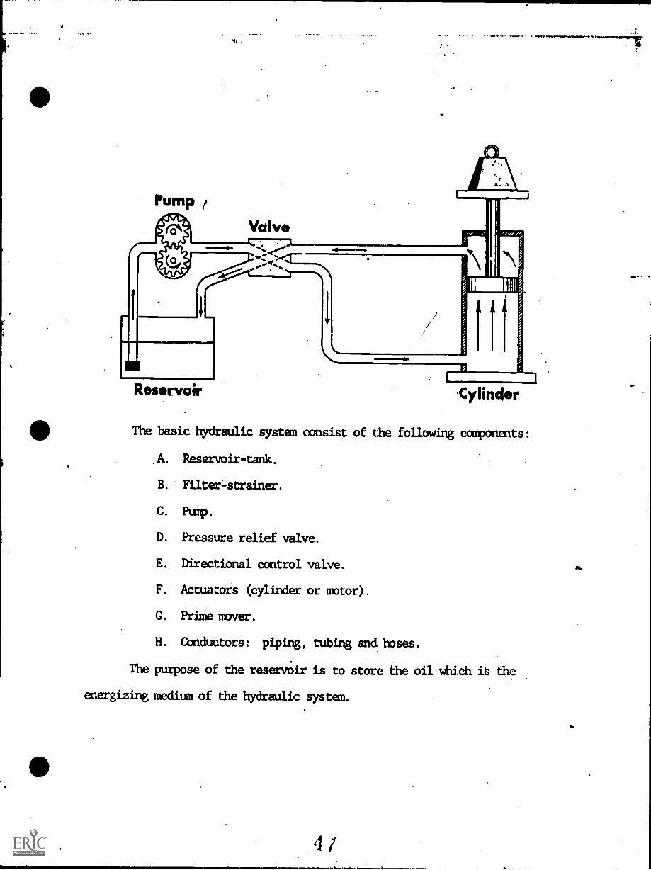
Pump r
Valve
Reservoir 'Cylinder
The basic hydraulic system consist of the following components:
A. Reservoir-tank.
B. Filter-strainer.
C. Pump.
D. Pressure relief valve.
E. Directional control valve.
F. Actuatois (cylinder or motor).
G. Priniemver.
H. Conductors: piping, tubing and hoses.
The purpose of the reservoir is to store the oil which is the
energizing medium of the hydraulic system.
4
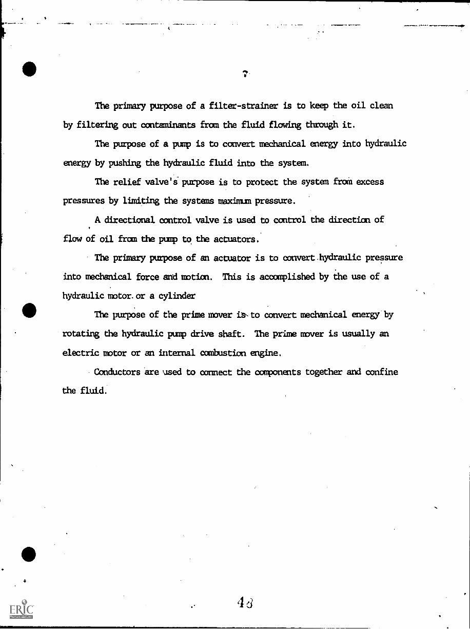
The primary purpose of a filter-strainer is to keep the oil clean
by filtering out contaminants fran the fluid flowing through it.
The purpose of a pump is to convert mechanical energy into hydraulic
energy by pushing the hydraulic fluid into the system.
The relief valve's purpose is to protect the system from excess
pressures by limiting the systems maxim= pressure.
A directional control valve is used to control the direction of
flow of oil from the pump to the actuators.
The primary purpose of an actuator is to convert hydraulic pressure
into mechanical force and notion. This is acccuplished by the use of a
hydraulic motor. or a cylinder
The purpose of the prime mover is to convert mechanical energy by
rotating the hydraulic pump drive shaft. The prime mover is usually an
electric motor or an internal combustion engine.
Conductors are used to connect the components together and confine
the fluid.
- d
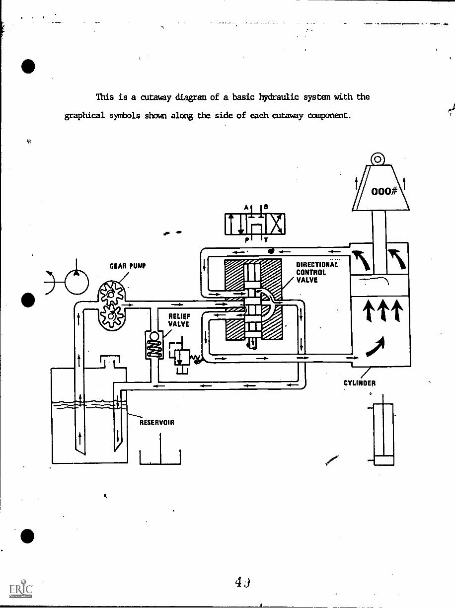
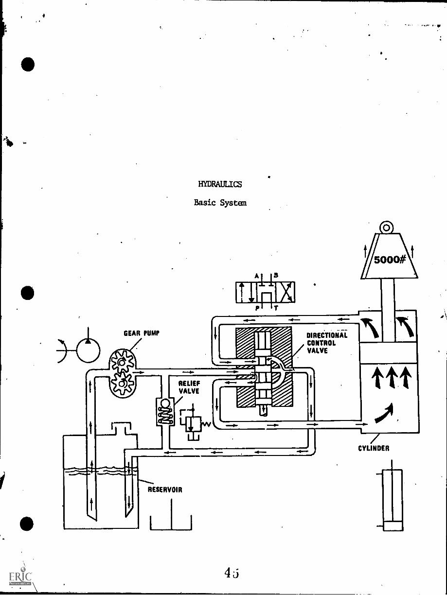
This is a cutaway diagram of a basic hydraulic systen with the
graphical symbols shown along the side of each cutaway component.
GEAR PUMP
RELIEFVALVE
4P
DIRECTIONAL 1111 111%CONTROLVALVE
RESERVOIR
4j
TTT
1/CYLINDER
6
NEM
.0.1121
INSTRUCTIONAL-LEARNING SYSTEMS
Job Sheet
I 17-1.......
A a
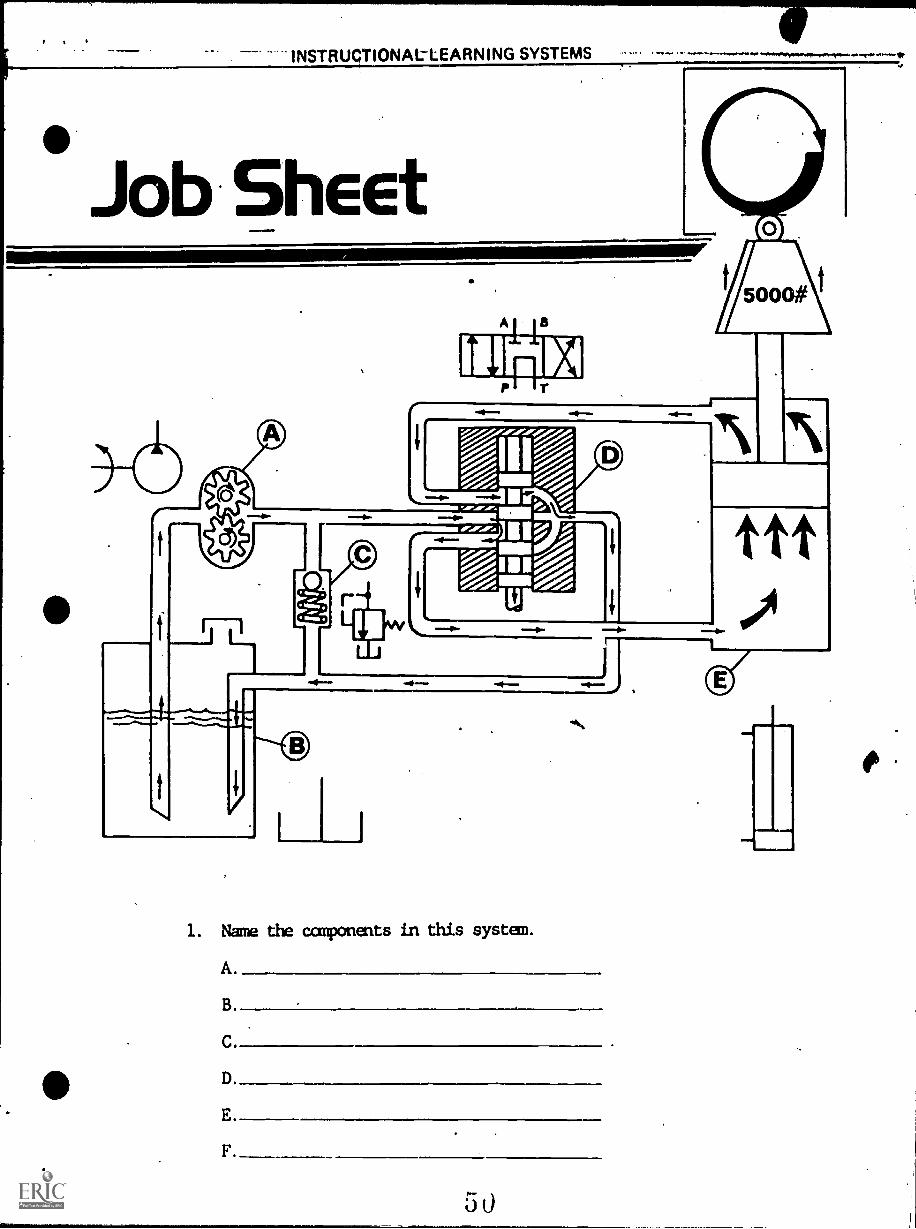
1. Name the canponents in this system.
A.
B
C.
D.
E.
F
50
ombl=1114
11.
KEY 'DO WORKSHEET
A. Purp.
B. Reservoir.
C. Relief valve.
D. Directional control valve.
E. Actuating cylinder.
F. Conductors.
da
51
INSTRUCTIONAL LEARNING SYSTEMS
a. ....nip vq
PosAss ssment
1
11,3
114.10111
4
POST-TEST
2
5
/50001\
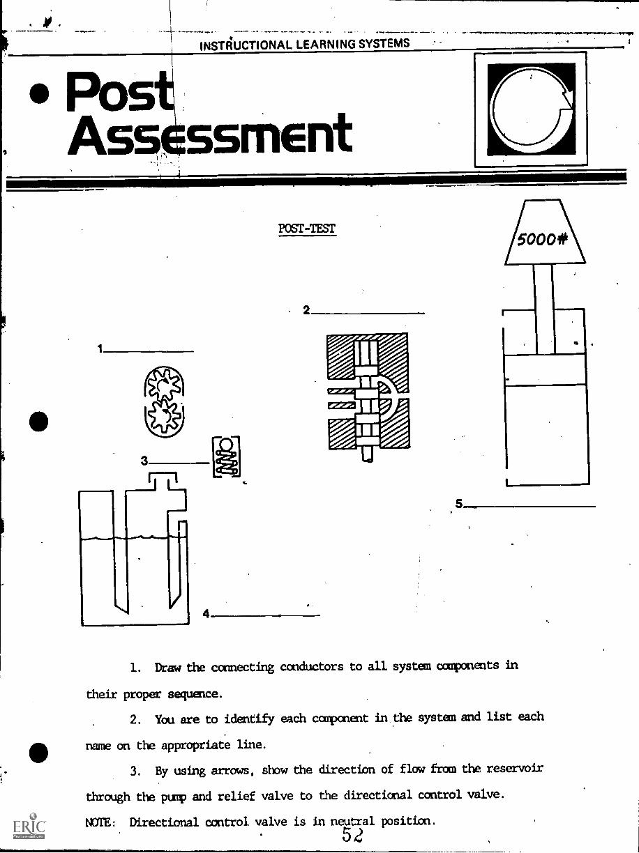
1. Draw the connecting conductors to all system components in
their proper sequence.
2. You are to identify each component in the system and list each
name on the appropriate line.
3. By using arrows, show the direction of flaw from the reservoir
through the pump and relief valve to the directional control valve.
NOTE: Directional control valve is in neutral position.
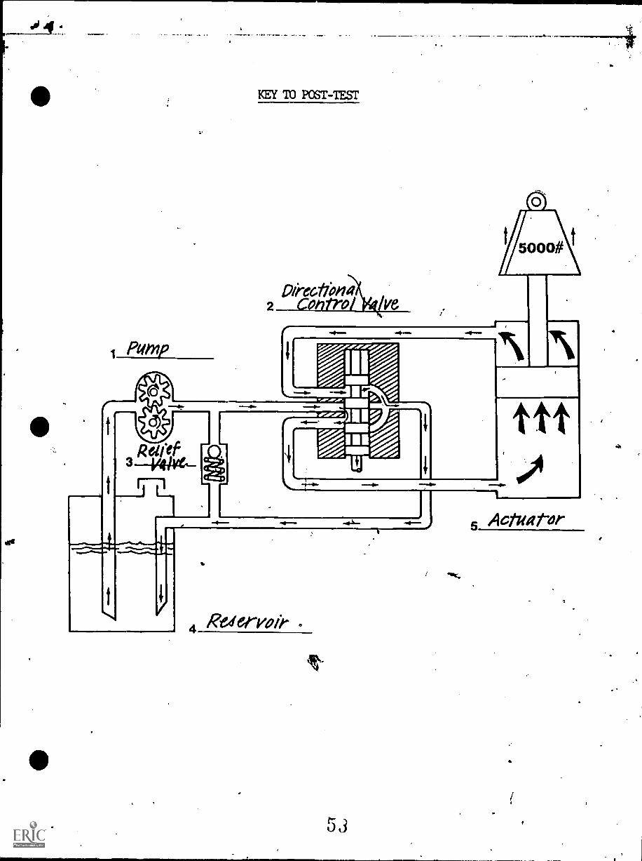
KEY 10 POST-TEST,
Pomp
Dikaffona2 cot7trol lye
5000#
Sr
Raervoie
4
53
ttt5 Actuator

1 C..10
4
16ffIXIIJ1/4.4.e0fIALL2211VICY.1.)
17.5
HYDRAULICS
IM-HY--05
fi
Pumps r
Goal;The studenL will be able to identifytypes of fluid power system pumpsand describe their opelation.
Performance Indicators:1. Given fluid power system pumps,
the student will name them bytype and identify their majorparts.
2. Given a schematic drawing of agear type pump, the student willtrade fluid flow into and outof the pump.
3. Given paper ana pencil, thestudent will write a paragraphdescribing the purpose of thepump in a fluid power system.
-ow
5i
ft
INSTRUCTIONAL LEARNING SYSTEMS
nformation
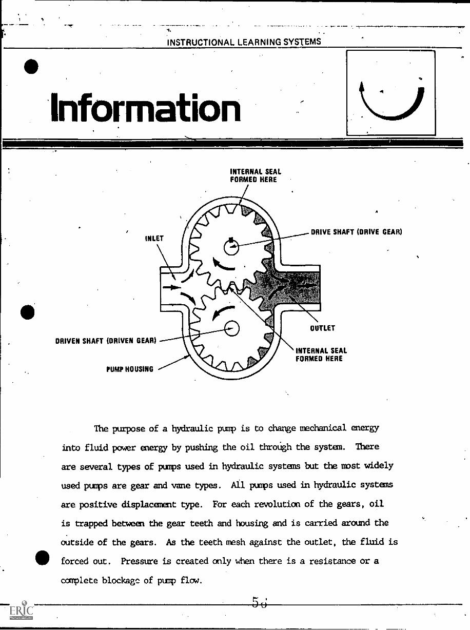
INLET
DRIVEN SHAFT (DRIVEN GEAR)
PUMP HOUSING
INTERNAL SEALFORMED HERE
A
DRIVE SHAFT (DRIVE GEAR)
INTERNAL SEALFORMED HERE
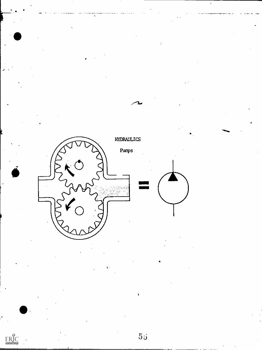
The purpose of a hydraulic pump is to change mechanical energy
into fluid power energy by pushing the oil throUgh the system. There
are several types of pumps used in hydraulic systems but the most widely
used pumps are gear and vane types. All pumps used in hydraulic systems
are positive displacement type. For each revolution of the gears, oil
is trapped between the gear teeth and housing and is carried around the
outside of the gears. As the teeth, mesh against the outlet, the fluid is
forced out. Pressure is created only when there is a resistance or a
complete blockagc of pump flow.
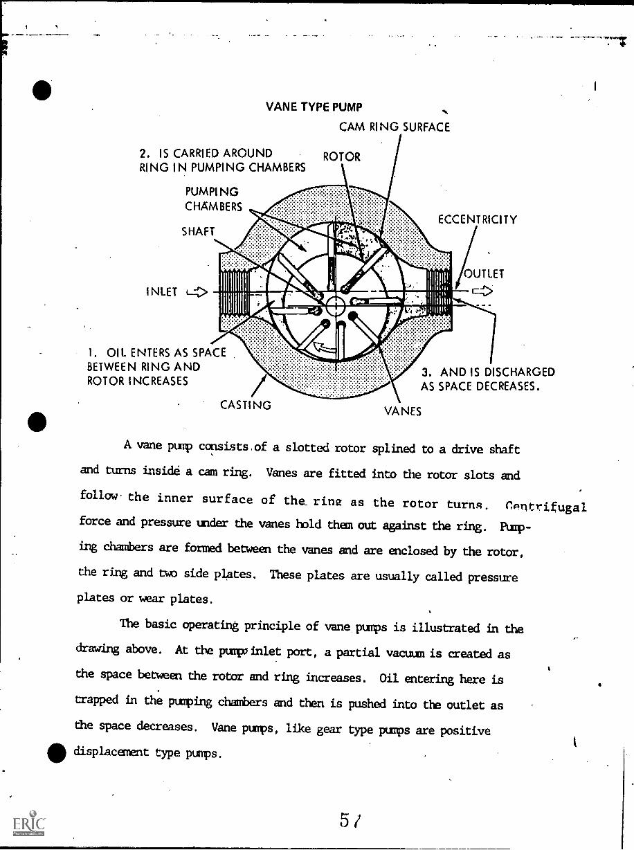
VANE TYPE PUMP
2. IS CARRIED AROUNDRING IN PUMPING CHAMBERS
INLET
PUMPINGCHAMBERS
SHAFT
CAM RING SURFACE
ROTOR
ECCENTRICITY
I. OIL ENTERS AS SPACEBETWEEN RING ANDROTOR INCREASES
3. AND IS DISCHARGEDAS SPACE DECREASES.
A vane pump consists.of a slotted rotor splined to a drive shaft
and turns inside a cam ring. Vanes are fitted into the rotor slots and
follow the inner surface of the_ rine as the rotor turns. CAntrifugalforce and pressure under the vanes hold than out against the ring. Pump-
ing chambers are formed between the vanes and are enclosed by the rotor,
the ring and two side plates. These plates are usually called pressure
plates or wear plates.
The basic operating principle of vane pumps is illustrated in the
drawing above. At the punk inlet port, a partial vacuum is created as
the space between the rotor and ring increases. Oil entering here is
trapped in the pumping chambers and then is pushed into the outlet as
the space decreases. Vane pumps, like gear type pumps are positive
displacement type pumps.
INSTRUCTIONAL LEARNING SYSTEMS
Assignment
o
LEARNING ACTIVITIES
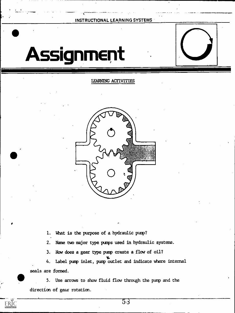
1. What is the purpose of a hydraulic pump?
2. Name two major type pumps used in hydraulic systems.
3. Now does a gear type pump create a flow of oil?
4. Label pump inlet, pump outlet and indicate where internal
seals are formed.
5. Use arrows to show fluid flow through the pump and the
direction of gear rotation.
4INSTRUCTIONAL LEARNING SYSTEMS
Job heet
WORKSHEET
If available, disassemble a gear or vane type pump.. Lay all
parts in an orderly manner to make it easier for reassembly.
Identify all parts of the pump. Reassemble pump. If a test bench is
available, test pump for proper flow and pressure.
INSTRUCTIONAL-LEARNING-SYSTEMS
PostAssessment
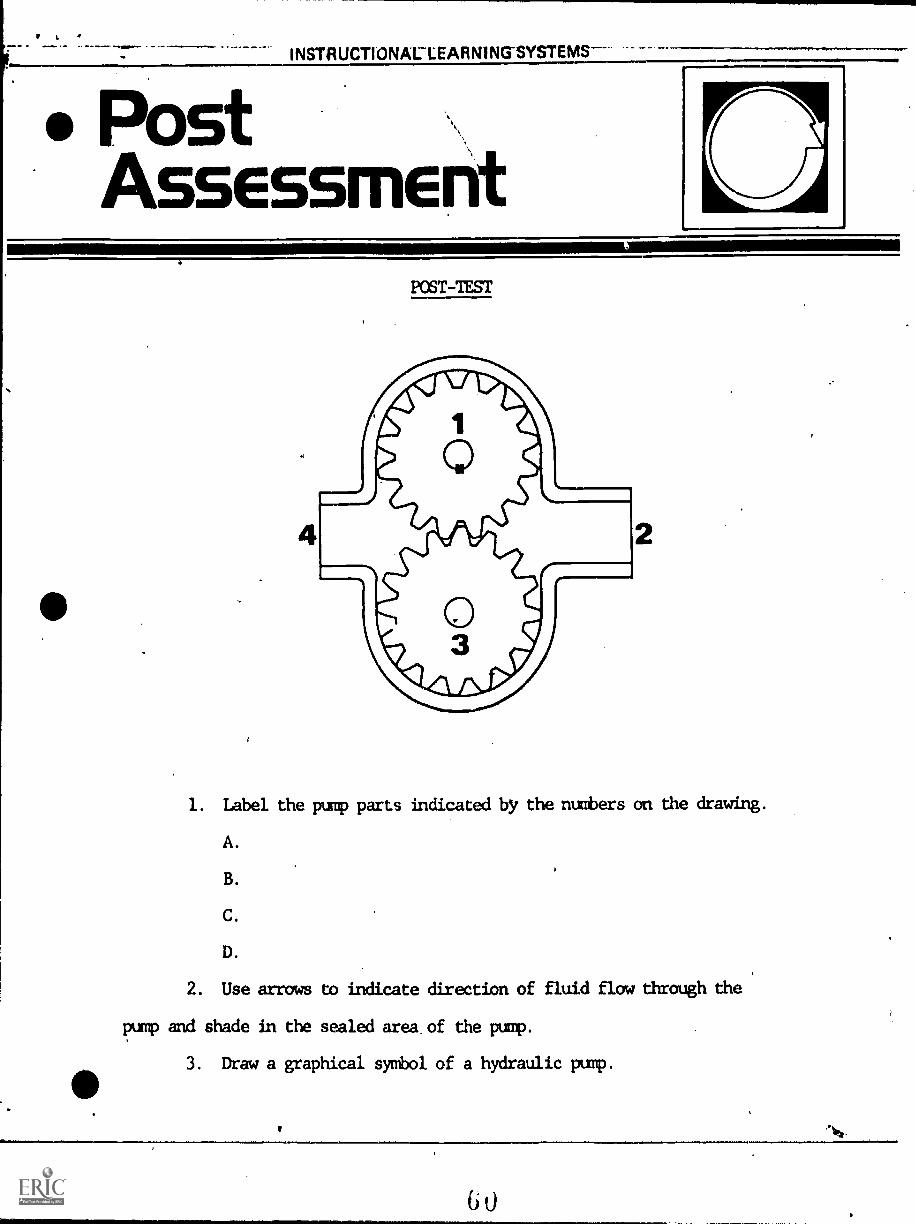
POST-TEST
1. Label the pump parts indicated by the numbers on the drawing.
A.
B.
C.
D.
2. Use arrows to indicate direction of fluid flow through the
pump and shade in the sealed area of the pump.
3. Draw a graphical symbol of a hydraulic pump.
6 0
KEY W posr-nsr.
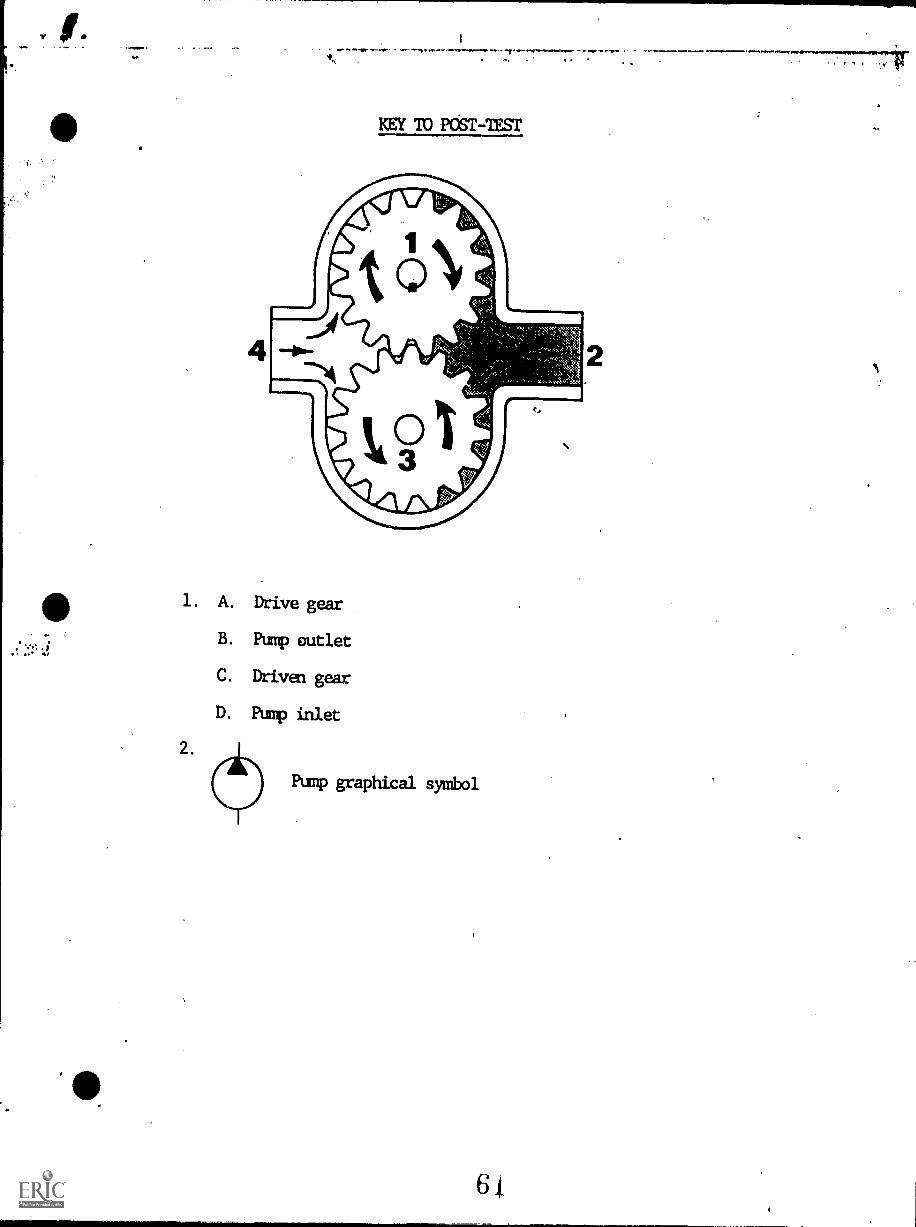
1. A. Drive gear
B. Pump outlet
C. Driven gear
D. Pump inlet
2.
Pump graphical symbol
6L
FLWIUMOOAL L 4T K YeNk.sal
6
HYDRAULICS
IM-HY-06
Pressure Relief Valve
Goal:The student will know the functionof a relief valve in thehydraulic system.
Performance Indicators:1. Given a relief valve and a
hydraulics system, the studentwill correctly install thevalve in the system and adjustsystem pressure.
2. Given a sketch of a relief valve,the student will identify sixbasic parts in writing.
3. Given paper and pencil, thestudent will write a paragraphon the purpose of the reliefvalve in a hydraulics system.
6'
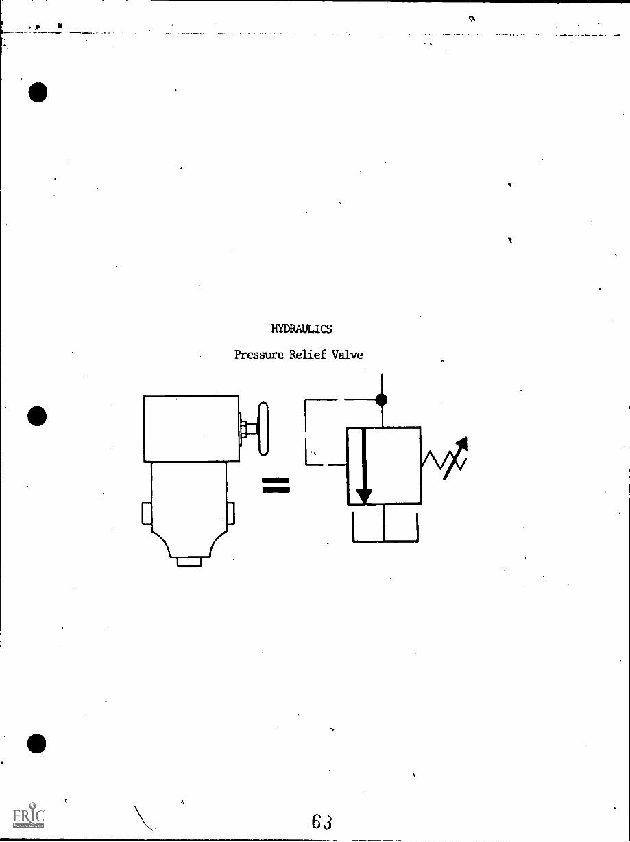
HYDRAULICS
Pressure Relief Valve
A
63
INSTRUCTIONAL LEARNING SYSTEMS
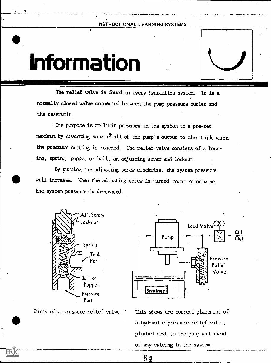
nformationThe relief valve is found in every hydraulics system. It is a
normallyclosedyalve connected between the pump pressure outlet and
the reservoir.
Its purpose is to limit pressure in the system to a pre-set
maxinun by diverting same oPall of the pump's output to the tank when
the pressure setting is reached. The relief valve consists of a hous-
ing, spring, poppet or ball, an adjusting screw and locknut.
By turning the adjusting screw clockwise, the system pressure
will increabe. When the adjusting screw is turned counterclockwise
the system pressure is decreased.
Mj. ScrewLocknut
Spring
Tank1"-Port
Ball orPoppet
Pressure
Port
Parts of a pressure relief valve.
Pump
r 1
1-Stra inesj
Load Valve
Pressure
Re I ief
Valve
This shows the correct placeLent of
a hydraulic pressure reliqf valve,
plumbed next to the pump and ahead
of any valving in the system.
/
4
./INSTRUCTIONAL LEARNING SYSTEMS
Assignment
1. Disassemble a pressure relief valve if one is available
and name all internal and external parts.
A.
B.
C.
D.
E.
F.
A IAIP"
INSTRUCTIONAL LEARNING SYSTEMS
SelfAssessment
SELF-TEST
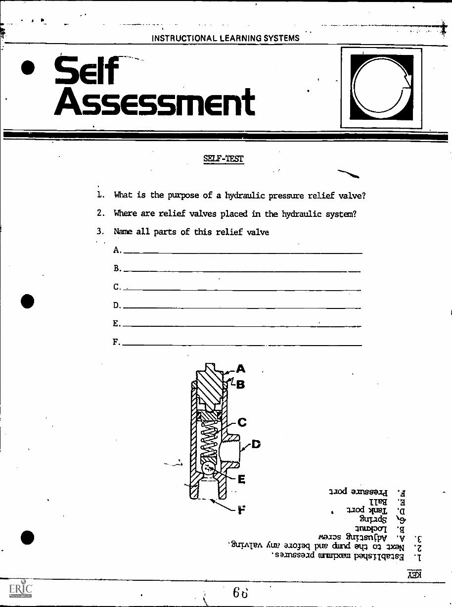
1. What is the purpose of a hydraulic pressure relief valve?
2. Where are relief valves placed in the hydraulic system?
3. Name all parts of this relief valve
A
B.
C.
D.
E.
F.
32od eanssead
LIES *2aiod .a
ids3nupoi
moms arpsn0011*IV *E
.2uppA Cue aiogaq pure dund eql 43.59N .z
samssaid arexpcem patismulsa
f 111.1
1.
amb11.4"IUMOUL LEATEIX
17.7
HYDRAULICS
IM-H"-07 Reservoirs
A
Goal:
The student will know the basicstructure and function of thehydraulics reservoir.
1
Performance Indicators:1. Given a hydraulic reservoir,
the student will explain itspurpose' and use and identifyit by type.
2. Given a schematic drawing of ahydraulic reservoir, the studentwill sketch in the parts andcorrectly name them.
61
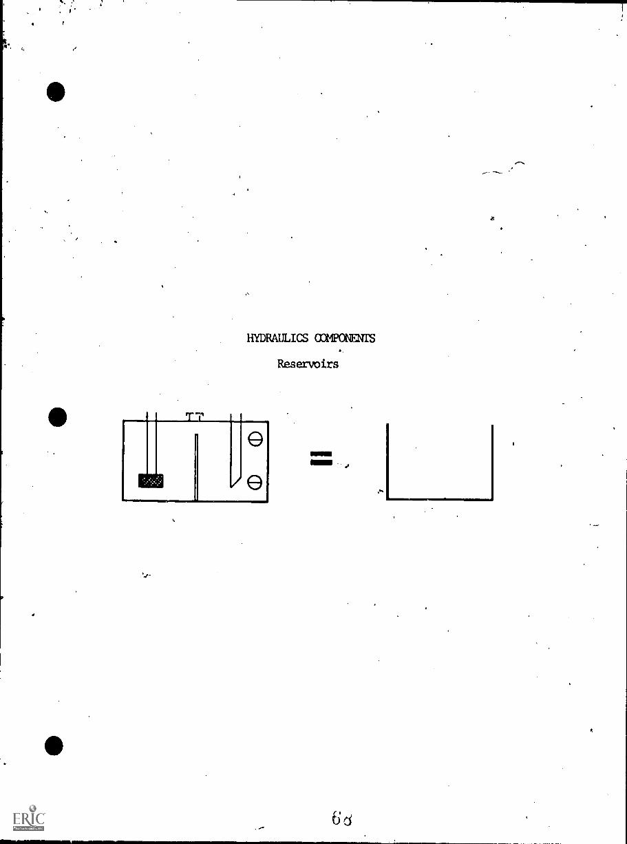
HYDRAULICS COMPONENIS
"al
/e
Reservoirs
111111111111
11=1111
6d
INSTRUCTIONAL LEARNING SYSTEMS
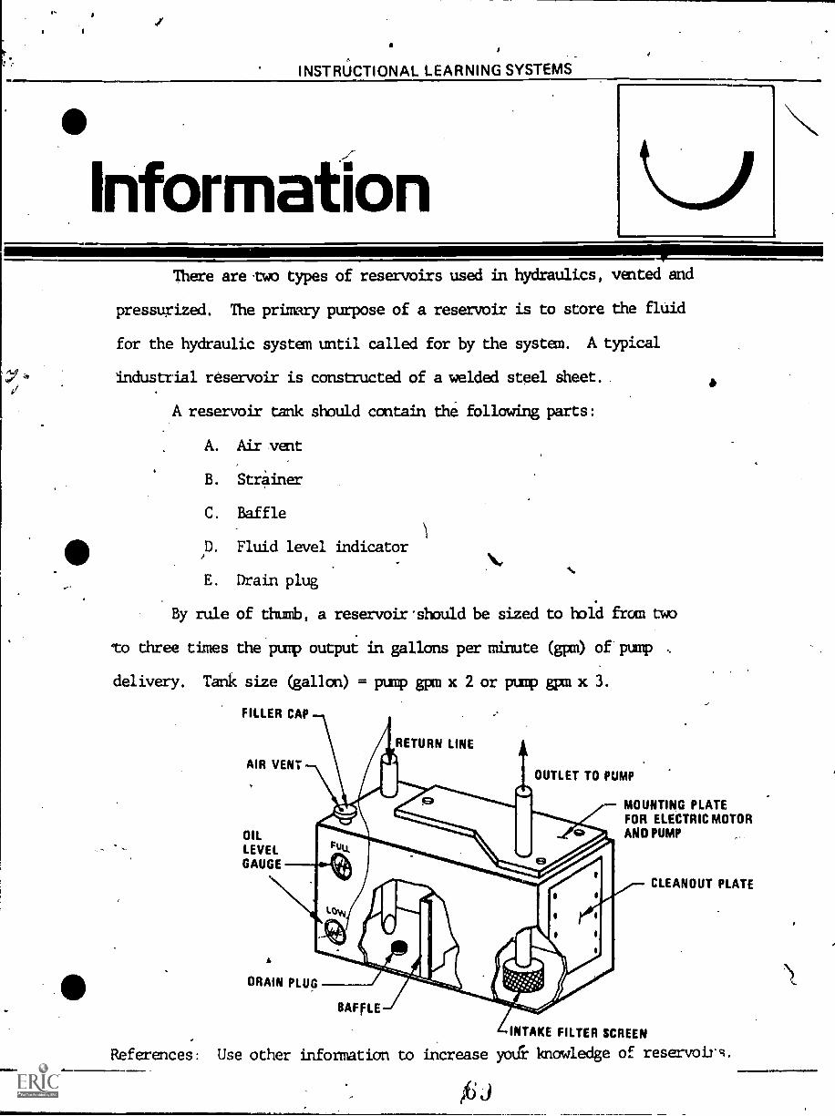
InformationThere are two types of reservoirs used in hydraulics, vented and
pressugized. The primary purpose of a reservoir is to store the fluid
for the hydraulic system until called for by the system. A typical
industrial reservoir is constructed of a welded steel sheet.
A reservoir tank should contain the following parts:
A. Air vent
B. Striner
C. Baffle
D. Fluid level indicator
E. Drain plug
By rule of thumb, a reservoir .should be sized to hold from two
to three times the pub output in gallons per minute (gpm) of pump
delivery. Tank size (gallon) = pump gpm x 2 or pump gpm x 3.
FILLER CAP
RETURN LINE
Nhv
AIR VENT
OILLEVELGAUGE
OUTLET TO PUMP
I
MOUNTING PLATEFOR ELECTRIC MOTORAND PUMP
DRAIN PLUG
BAFFLE
References: Use other information to increase
INTAKE FILTER SCREEN
knowledge of reservoirs.
CLEANOUT PLATE
INSTRUCTIONAL LEARNING SYSTEMS
kssi nment
IP
LEARNING ACTIVITIES
1. Examine a reservoir on a working hydraulic system and
locate the following components:
A. Breather and filler cap.
Fluid level indicator.
d. Return line.
D. Pump inlet line.
E. Return line filter.
INSTRUCTIONAL LEARNING SYSTEMS
7
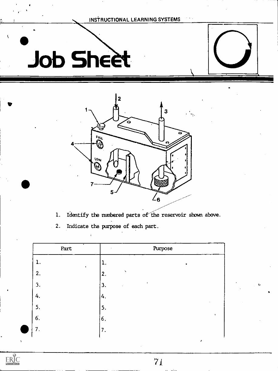
1. Identify the numbered parts of4le reservoir shown above.
Indicate the purpose of each part.
INSTRUCTIONAL LEARNING SYSTEMS
5 IfAssessment
1
SELF-TEST
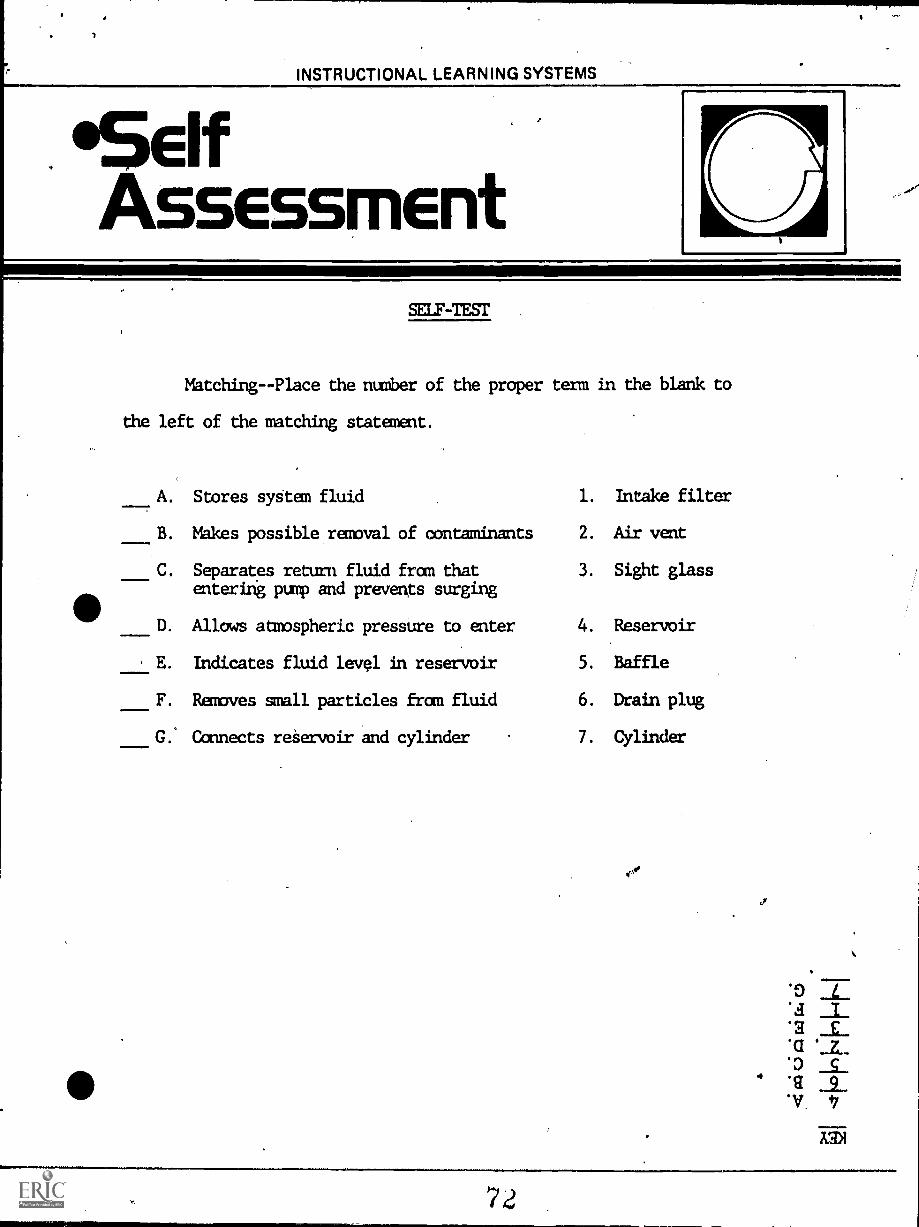
Matching -Place the number of the proper term in the blank to
the left of the matching statement.
A. Stores system fluid 1. Intake filter
B. Makes possible removal of contaminants 2. Air vent
Separates return fluid from thatentering pump and prevents surging
3. Sight glass
D. Allows atmospheric pressure to enter 4. Reservoir
E. Indicates fluid level in reservoir 5. Baffle
F. Removes small particles from fluid 6. Drain plug
G. Connects reservoir and cylinder 7. Cylinder
INSTRUCTIONAL LEARNING SYSTEMS
'PostAssessment
.44
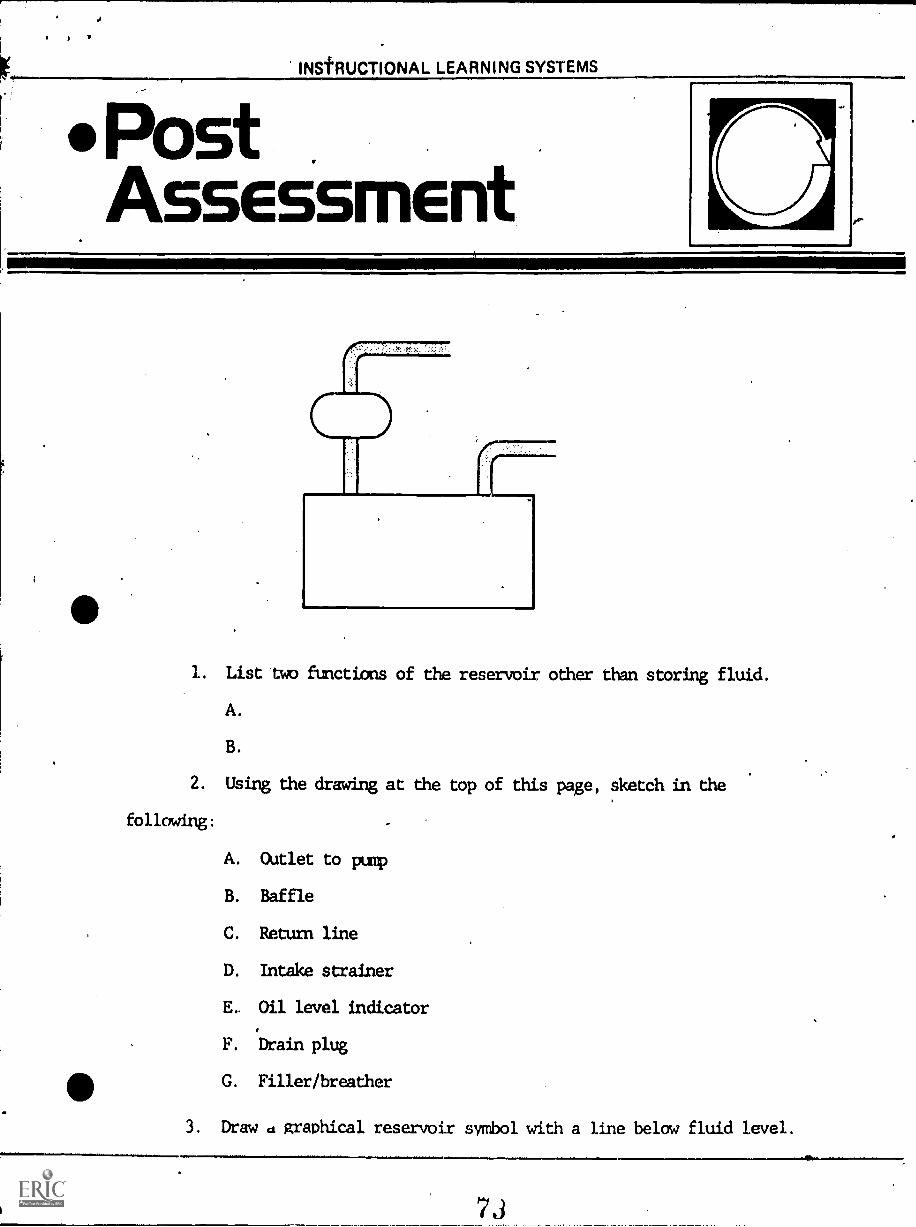
1. List two functions of the reservoir, other than storing fluid.
A.
B.
2. Using the drawing at the top of this page, sketch in the
following:
A. Outlet to pump
B. Baffle
C. Return line
D. Intake strainer
E. Oil level indicator
F. Drain plug
G. Filler/breather
3. Draw d graphical reservoir symbol with a line below fluid level.
OUTLET TO PUMP
CLEANOUT PLATE
STRAINER
3.
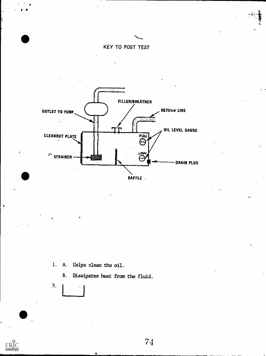
KEY TO POST TEST
FILLER/BREATHER
RETUhd LINE
rrrFULL
LoW
rusameamsaamuft
BAFFLE
Uelps clean the oil.
B. Dissipates heat fran the fluid.
71
OIL LEVEL GAUGE
ORAIN PLUG
BUVIUMOtlattLiAwsnc)tamal
17.8
HYDRAULICS
IM-HY-08
Directional Control Valve
Goal:
The student will be able to tracefluid flow through a directionalcontrol valve in a hydraulic system.
Performance Indicators:
1. Given the internal workingparts of a directional controlvalvq, the student will explainthe function of all movableparts.
2. Given paper and pencil, thestudent will draw a schematicof a directional control valve,showing all parts and the flow
of fluid through the valve.
to.
INSTRUCTIONAL LEARNING SYSTEMS
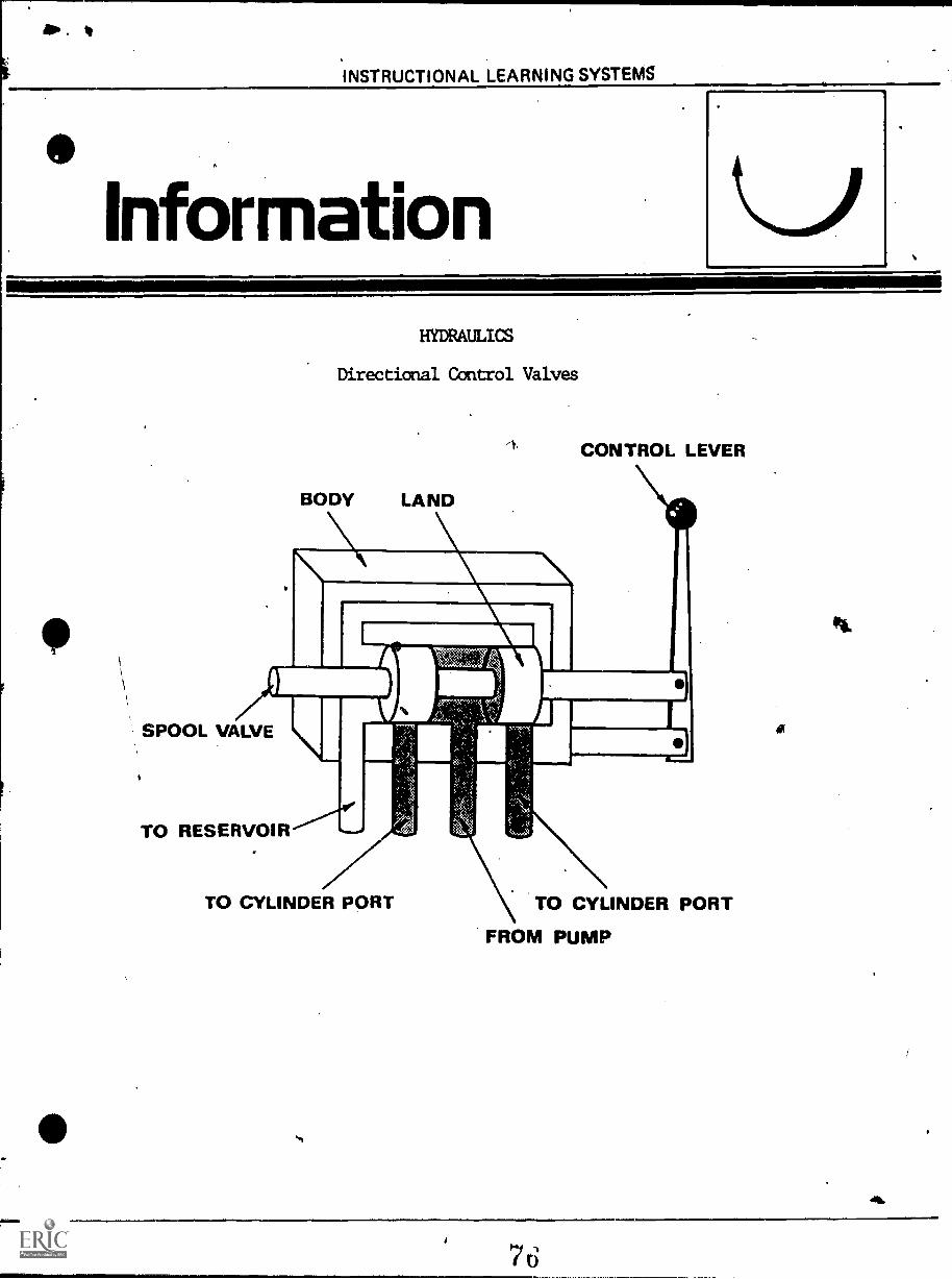
nformationHYDRAULICS
Directional Control Valves
CONTROL LEVER
SPOOL VALVE
TO RESERVOIR
TO CYLINDER PORT TO CYLINDER PORT
FROM PUMP
04.
allo. II
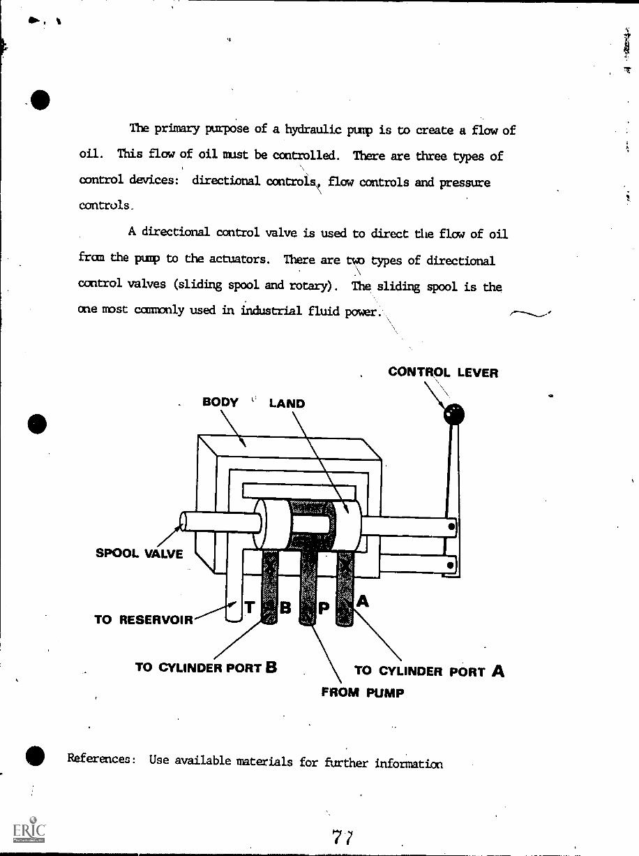
The primary purpose of a hydraulic pump is to create a flow of
oil. This flow of oil must be controlled. There are three types of
control devices: directional controls flow controls and pressure
controls.
A directional control valve is used to direct the flow of oil
fram the pump to the actuators. There are two types of directional
control valves (sliding spool and rotary). The sliding spool is the
one most commonly used in industrial fluid power.
BODY LI LAND
CONTROL LEVER
SPOOL VALVE
TO RESERVOIR
TO CYLINDER PORT B TO CYLINDER PORT A
FROM PUMP
410 References: Use available materials for further information
INSTRUCTIONAL LEARNING SYSTEMS
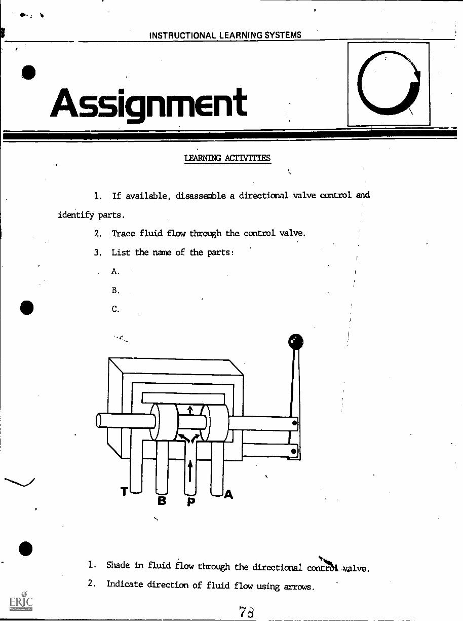
AssignmentLEARN= ACTIVITIES
1. If available, disassemble a directional valve control and
identify parts.
2. Trace fluid flow through the control valve.
3. List the name of the parts:
A.
B.
C.
-c_
ti
1. Shade in fluid flow through the directional conNA,valve.
2. Indicate direction of fluid flow using arrows.
INSTRUCTIONAL LEARNING SYSTEMS
PostAssessment
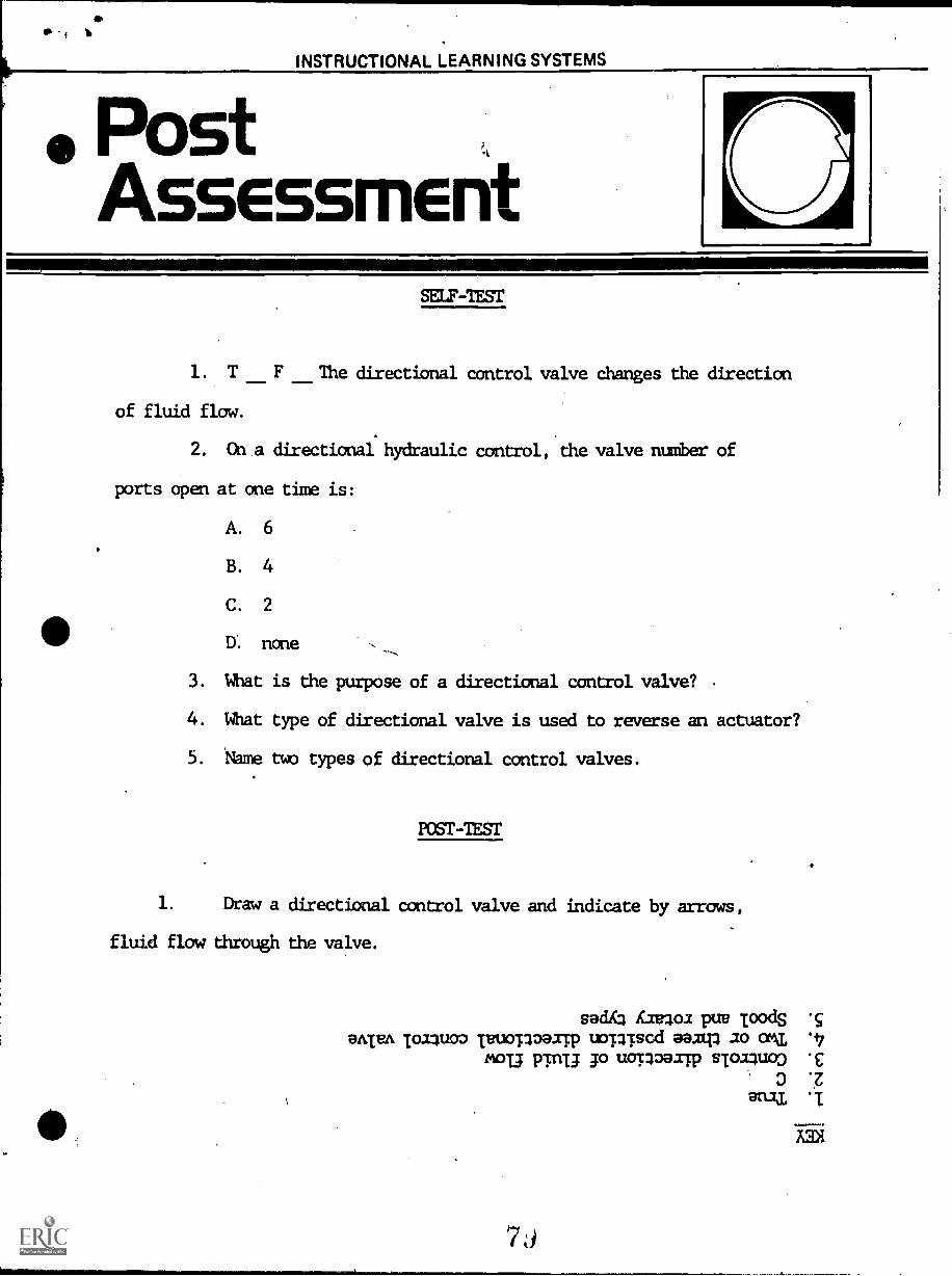
SELF-TEST
1. T F The directional control valve changes the direction
of fluid now.
2. Ct a directional hydraulic control, the valve number of
ports open at one time is:
A. 6
B. 4
C. 2
D. none
3. What is the purpose of a directional control valve?
4. What type of directional valve is used to reverse an actuator?
5. thme two types of directional control valves.
posr-ZEST
1. Draw a directional control valve and indicate by arrows,
fluid flow through the valve.
sad Aaeloa pue ToodS9A/VA Toaluoo TeuorloaaTp uomscd as am ao on 9 7
£'T3 pTnu Jo uopoaap sToalupo .c
0 ',Z
aruI
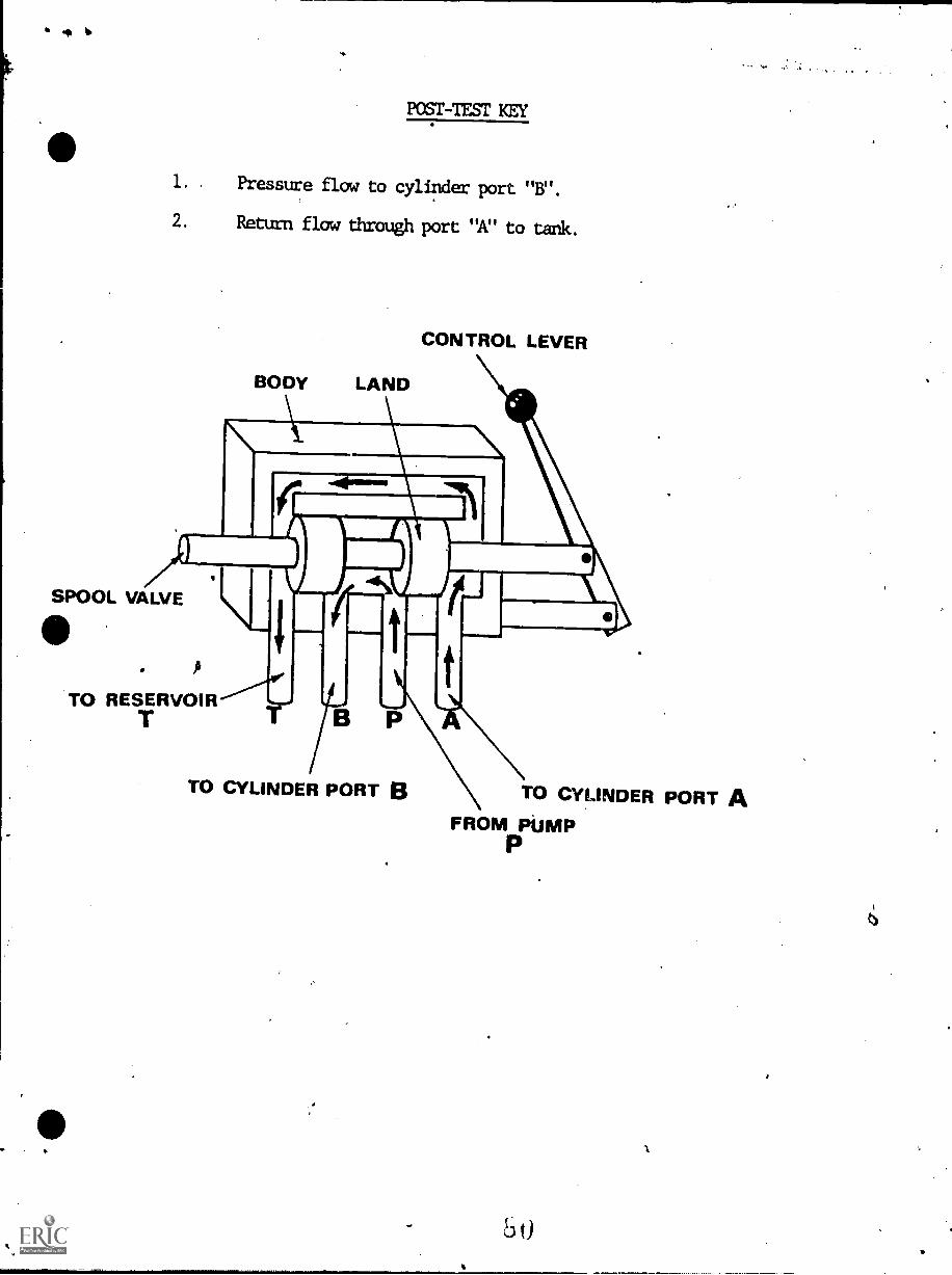
POST -TEST KEY
1. . Pressure flow to cylinder port "B".
2. Return flow through port "A" to tank.
BODY LAND
SPOOL VALVE
ft
TO RESERVOIRT
CONTROL LEVER
TO CYLINDER PORT B TO CYLINDER PORT AFROM PUMP
KLICRULTfOtIAL 12/AMC YOU
17.9
HYDRAULICS
IM-HY-09
Cylinders
I
Goal:
The student will know the structureand operation of actuating cylinders.
Performance Indicators:
1. Given the common parts of adouble-acting cylinder, thestudent will sketch fluid flowthroug: the cylinder.
2. Given three types of actuatingcylinders, the student willidentify them and indicate theirpurpose.
3. Given two sizes of actuatingcylinders, the student willcompute the output force andvolume of each cylinder.
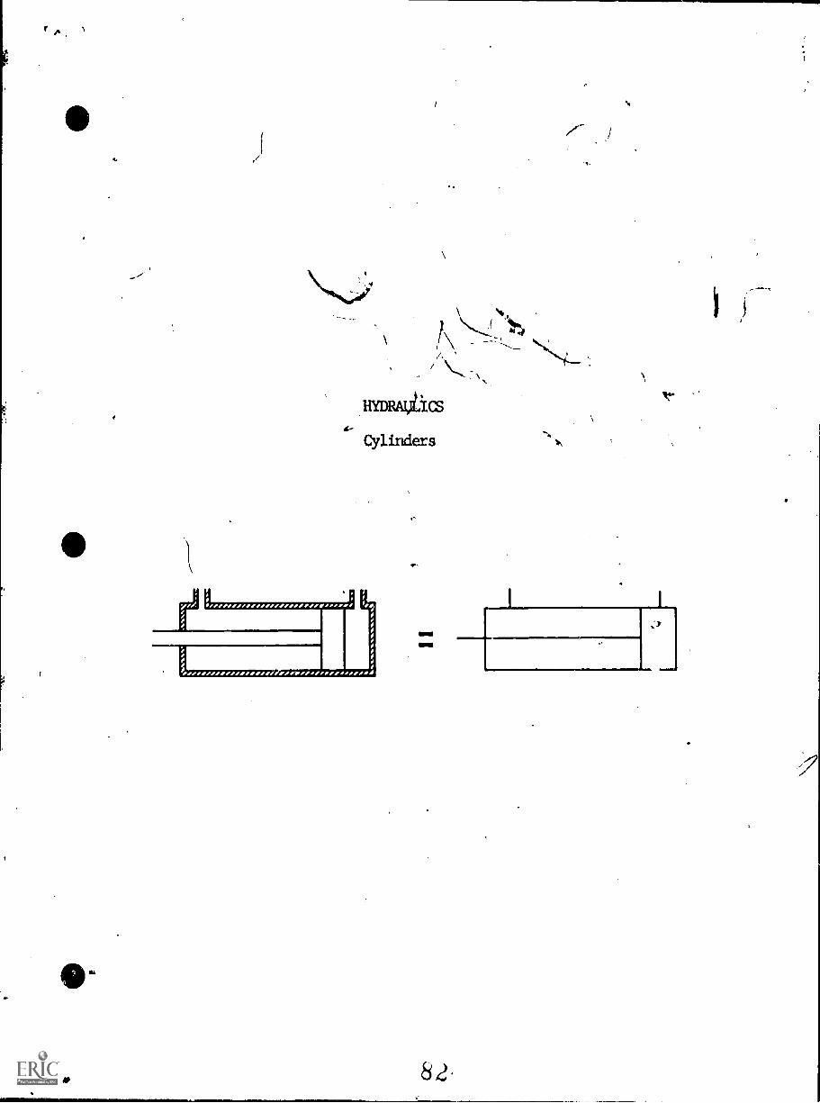
Cylinders
r
82
JIM
INSTRUCTIONAL LEARNIN _ SYSTEMS
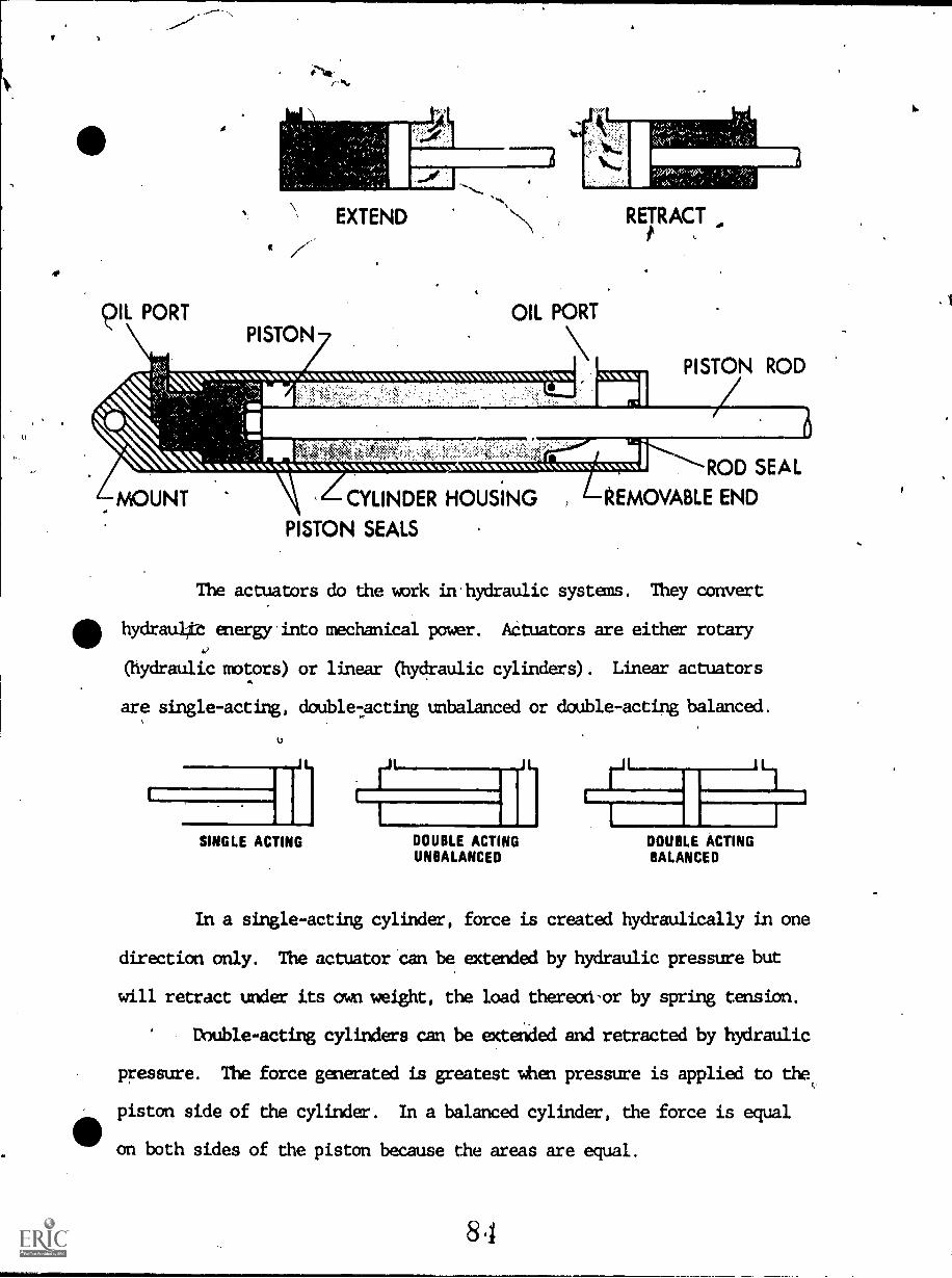
The actuators do the work in the hydraulic system. They convert
fluid energy to mechanical power. There are three types of linear actuators
used in fluid power systems. Single-acting, double-acting and balanced
cylinders give force in both ections. Pressurized oil is admitted
first at one end of the cylin then at the other giving two-way power.
A movable piston slides in a cylinder housing or barrel in response
to pressurized-oil entering the cylinder. The piston uses packings or seals
to prevent leakage of the oil between the piston and the cylinder wall.
Leakage past the piston rod is prevented by packing/in the cylinder end
cap. The speed of a cylinder is determined by the size of the actuator
and the quantity of oil pumped into it.,
The volume of a cylinder can be found by multiplying the cylinder
length times its area (V = L x A) which-will be i4 cubic inches. There are
231 cu. in. in a gallon of liquid.
83
c)IL PORT
I
PISTON
EXTEND
OIL PORT
RETRACTt
NIIMMANMANW.01014MVOAVONWOOMNVIWWWWWNVONVOA PISTON ROD
m!!!
1611A110014:WOMI1ANMOONV1/41000014104MMM V141001V10~10000NWV14"4:44VVtAN ROD SEAL
MOUNT CYLINDER HOUSING REMOVABLE END
PISTON SEALS
The actuators do the work in hydraulic systems. They convert
hydrau4c energy into mechanical power. Actuators are either rotary
(hydraulic motors) or linear (hydraulic cylinders). Linear actuators
are single-acting, double-acting unbalanced or double-acting balanced.
iflSINGLE ACTING
I
LII=1..111 1
DOUBLE ACTING DOUBLE ACTINGUNBALANCED BALANCED
In a single-acting cylinder, force is created hydraulically in one
direction only. The actuator can be extended by hydraulic pressure but
will retract under its own weight, the load thereon-or by spring tension.
Double-acting cylinders can be extended and retracted by hydraulic
pressure. The force generated is greatest when pressure is applied to the
piston side of the cylinder. In a balanced cylinder, the force is equal
on both sides of the piston because the areas are equal.
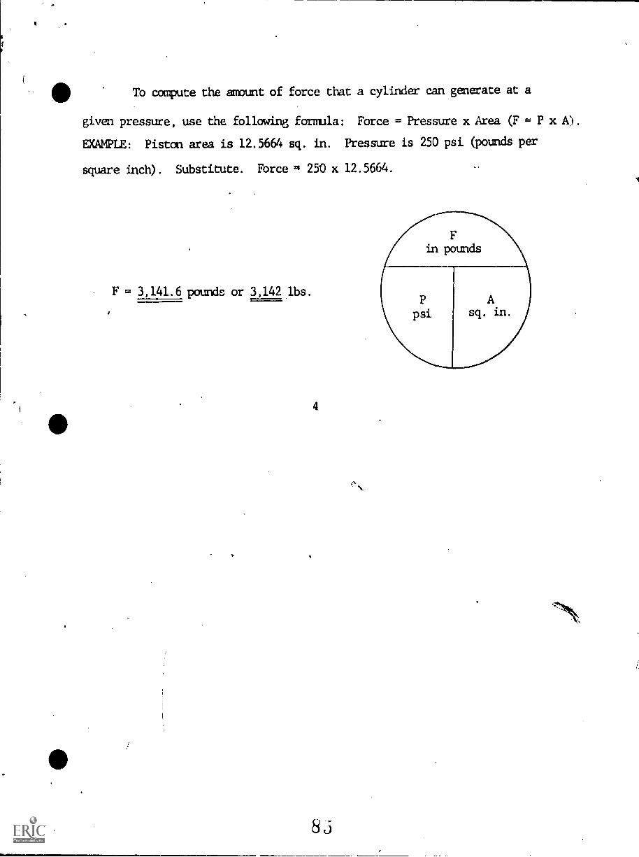
To compute the amount of force that a cylinder can generate at a
given pressure, use the following formula: Force = Pressure x Area (F = P x A).
EXAMPLE: Piston area is 12.5664 sq. in. Pressure is 250 psi (pounds per
square inch). Substitute. Force q 250 x 12.5664.
F = 3,141.6 pounds or 3,142 lbs.
83
INSTRUCTIONAL LEARNING SYSTEMS.
AssignmentiB
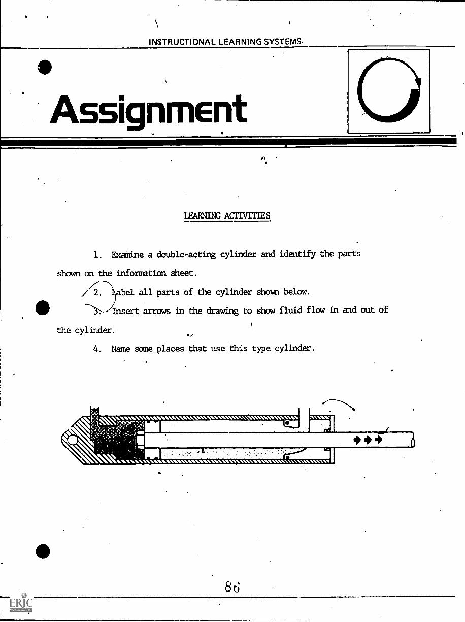
LEARNING ACTIVITIES
1. Examine a double-acting cylinder and identify the parts
shown on the information sheet.
// 2. label all parts of the cylinder shawl below.
Insert arrows in the drawing to show fluid flow in and out of
the cylinder.
4. Name sane places that use this type cylinder.
s\s\411111.. "VV1010101ANWINVIMIMIMIIMIsMINWOMIIMANVINVVVWNAMOVVIA"
INSTRUCTIONAL LEARNING SYSTEMS
Job Shed
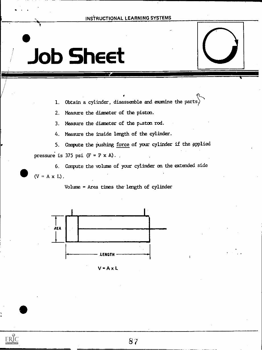
1. Obtain a cylinder, disassemble and examine the part
2. Measure the diameter of the piston.
3. Leasure the diameter of the piston rod.
4. Measure the inside length of the cylinder.
5. Compute the pushing force of your cylinder if the Applied
pressure is 375 psi (F = P x A).
6. Compute the volume of your cylinder on the extended side
(v = A x L).
Volume = Area times the. length of cylinder
REA
LENGTH
V=AxL
.11 INSTRUCTIONAL LEARNING SYSTEMS
ElfAssessment
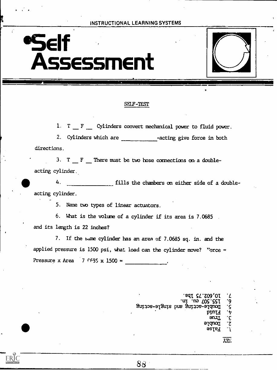
SELF-TEST
1. T __.F Cylinders convert mechanical power to fluid power.
2. Cylinders which are -acting give force in both
directions.
3. T F There must be two hose connections on. a double-
acting cylinder.
O 4.
acting cylinder.
Mml=11
fills the chambers on either side of a double-
5. Name two types of linear actuators.
6. What is the volume of a cylinder if its area is 7.0685
and its length is 22 inches?
7. If the same cylinder has an area of 7.0685 sq. in. and the
applied pressure is 1500 psi, what load can the cylinder move? "orce
Pressure x Area 7 r635 x 1500 =
'STE WZO9d0I .L
'UT "ID LOC*551 .92u-pov-K2uTs pug 2upoe-arroa 'S
PriaanAL £
amoa .z
asiva 1
AM;
88
taimill
INSTRUCTIONAL LEARNING SYSTEMS
'PostAssessmEnt
4)
POST-TEST
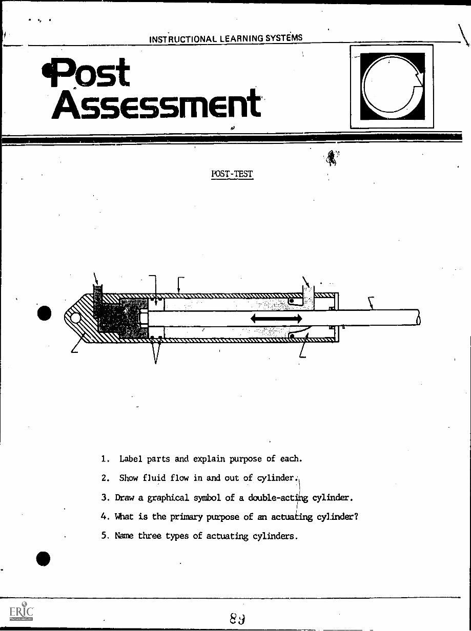
1. Label parts and explain purpose of each.
2. Show fluid flow in and out of cylinder.
3. Draw a graphical symbol of a double-act' cylinder.
4. What is the primary purpose of an actua ing cylinder?
5. Name three types of actuating cylinders.
11,
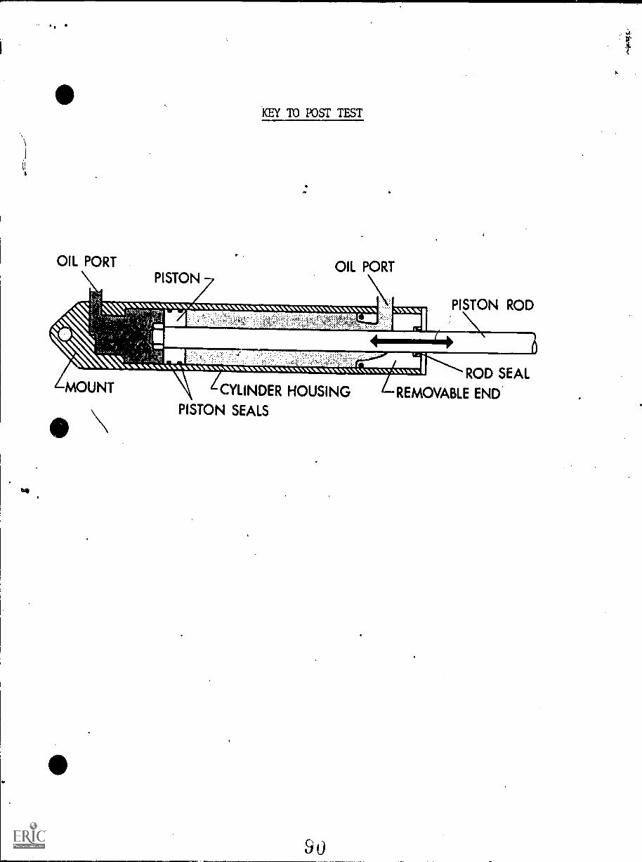
OIL PORTPISTON
KEY TO POST TEST
OIL PORT
PISTON ROD
111111111M1616.'. "11.11C\11:5;;11:11.1\\1111010101001010111/4100011\1101.1 MILVVOILV VIMILIVIA.N.MANNVIAVVV0:VONA"
MOUNT
\611
ROD SEALCYLINDER HOUSING REMOVABLE END.
PISTON SEALS
ti
0
O
.1111111Allowlb
Ni.)%UlrfiL LEARlinC YIN.M71.)
x.7.10
HYDRAULICS
IM-HY-10
Forces, Area, Pressure
Goal:The student will know the relation-ship of force, area and pressureto hydraulics.
1101111111101011111%
Performance Indicators:1. Given a basic hydraulic jack
outline, the student willsketch the hydraulic system.
2. Given an illustration of abasic hydraulic system completewith measurements, the studentwill compute force, pressure andarea to show a balanced system.
91
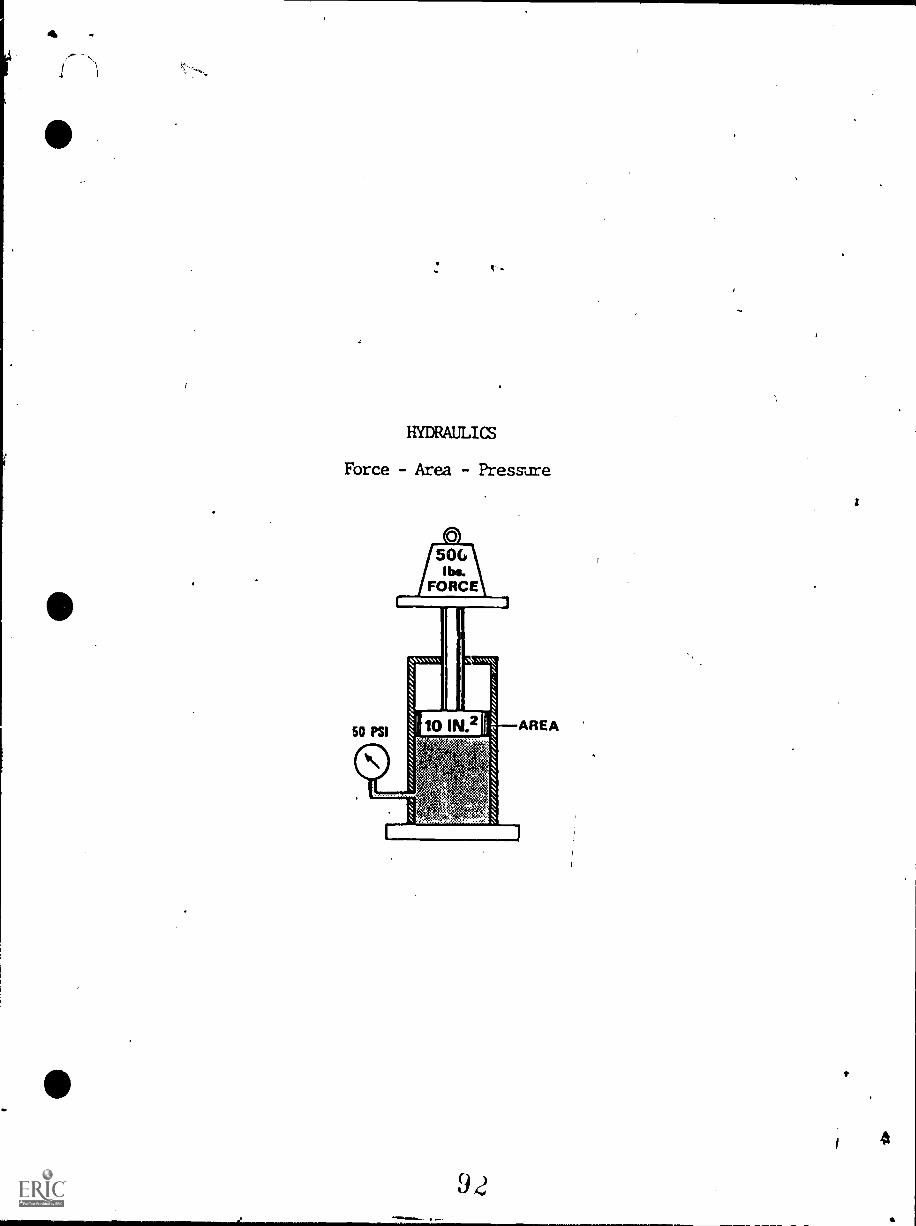
HYDRAULICS
Force - Area - Pressure
92
INSTRUCTIONAL LEARNING SYSTEMS
Information
INFOWATION SHFET
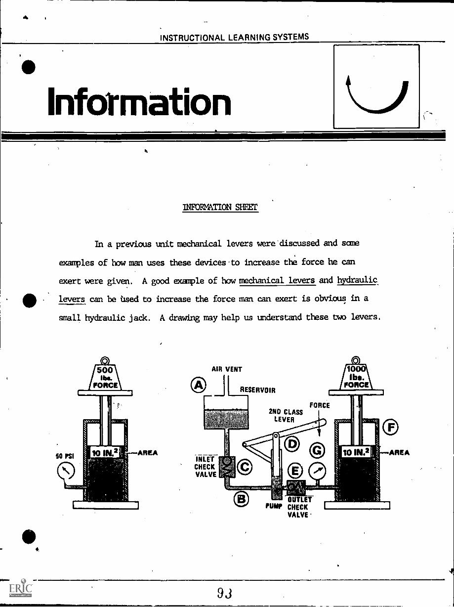
In a previous unit mechanical levers were discussed and some
examples of bowman uses these devices.to increase the force he can
exert were given. A good example of had mechanical levers and hydraulic
levers can be used to increase the force man can exert is obvious in a
small hydraulic jack. A drawing may help us understand these two levers.
AIR VENT
RESERVOIR
10ibt?\_
/FORCE
INLETCHECKVALVE
2NO CLASSLEVER
FORCE
AREA
OUTLEPUMP CHECK
VALVE'
93
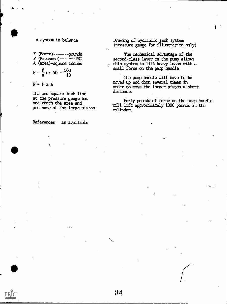
A system in balance
F (Force) poundsP (Pressure) PSIA (Area) - square inches
P = A:or 50 =500
F= P x A
The one square inch lineat the pressure gauge hasone-tenth the area andpressure of the large piston.
References: as available
Drawing of hydraulic jack system(pressure gauge for illustration only)
The mechanical advantage of thesecond-class lever an the pump allowsthis system to lift heavy loaas with asmall force on the pump handle.
The pump handle will have to bemoved up and down several times inorder to move the larger piston a shortdistance.
Forty pounds of force on the pump handlewill lift approximately 1000 pounds at thecylinder.
9 4
11.
INSTRUCTIONAL LEARNING SYSTEMS
Assignment
LEARNING ACITVITIES
1. Examdne hydraulic jacks of different capacities such as
lk ton, 5 ton and 1U ton to observe the differences in construction.
2. Measure the small and large pistons of these jacks andx
are their diameters.
3. Observe the handles for each jacK and determine the
advantage of increasing the length of the handle from the fulcrum.
4. Measure the travel on the small piston of a jack and
compare that travel with that of the large piston.
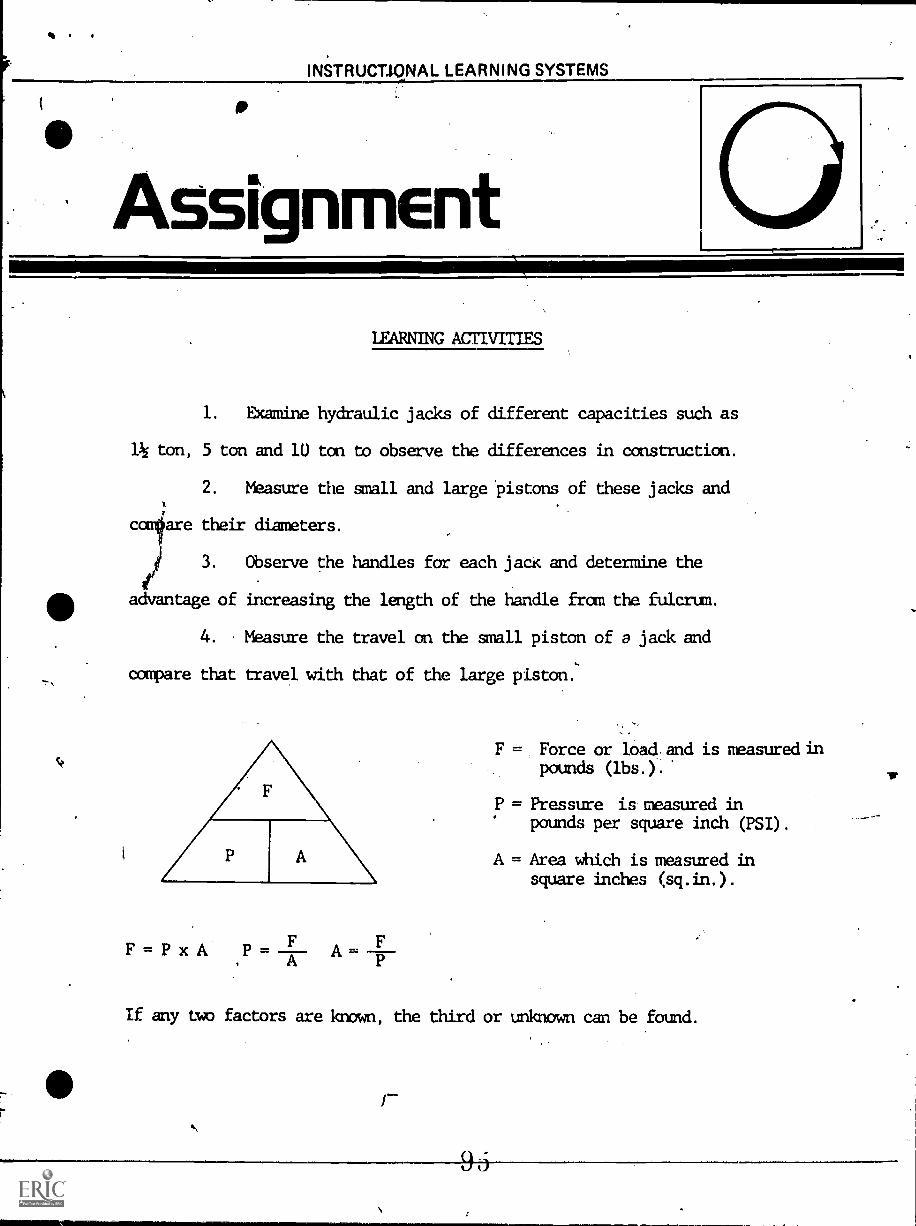
FF = P x A P=
AA
F
F = Force or load and is measured inpounds (lbs.).
P = Pressure is measured inpounds per square inch (PSI).
A = Area which is measured insquare inches (sq.in.).
If any two factors are known, the third or unknown can be found.
INSTRUCTIONAL LEARNING SYSTEMS
Job ShEEtWORKSHEETS
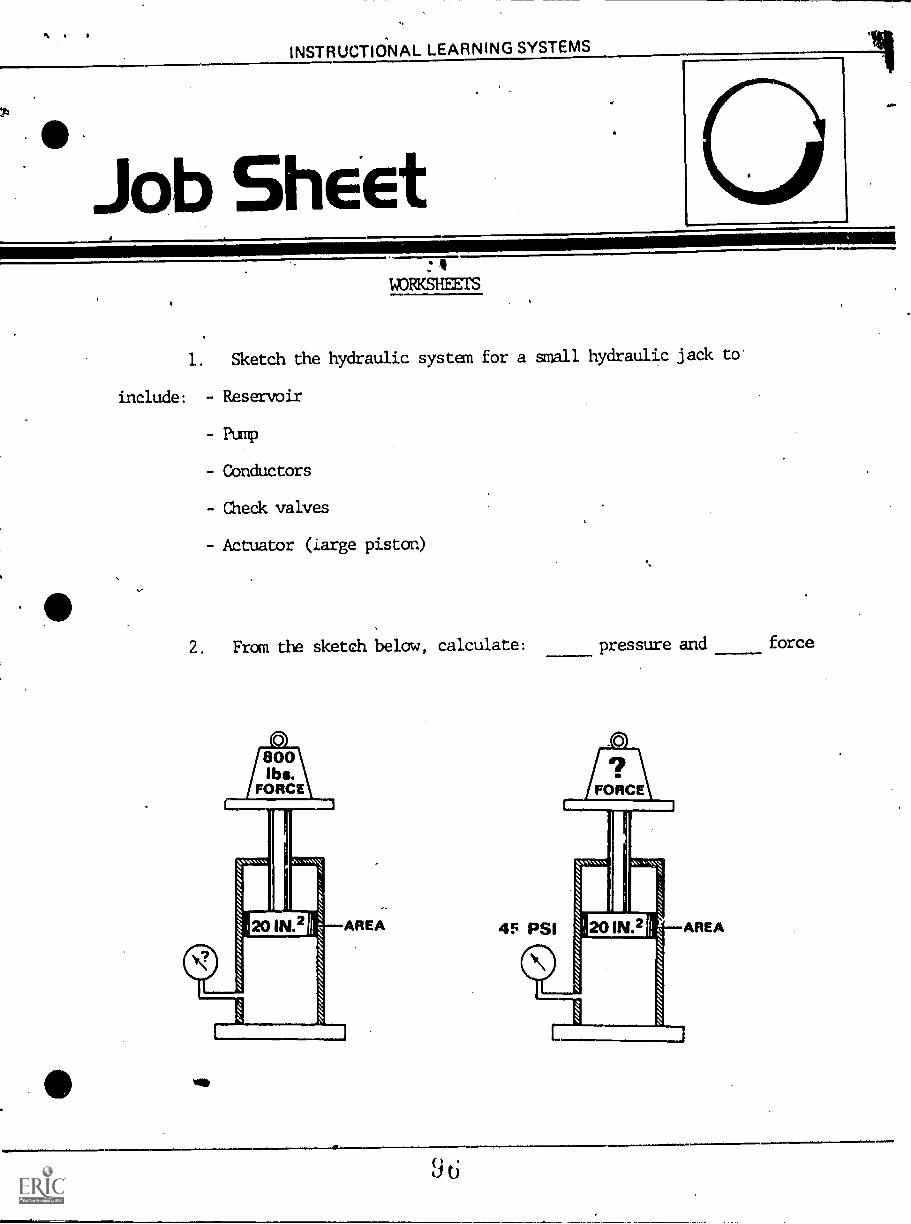
1. Sketch the hydraulic system for a small hydraulic jack to
include: - Reservoir
- Pump
- Conductors
- Check valves
- Actuator (large piston)
2. From the sketch below, calculate:
vie
pressure and force
11 .11 INSTRUCTIONAL LEARNING SYSTEMS
SelfAssessment
SELF-TEST
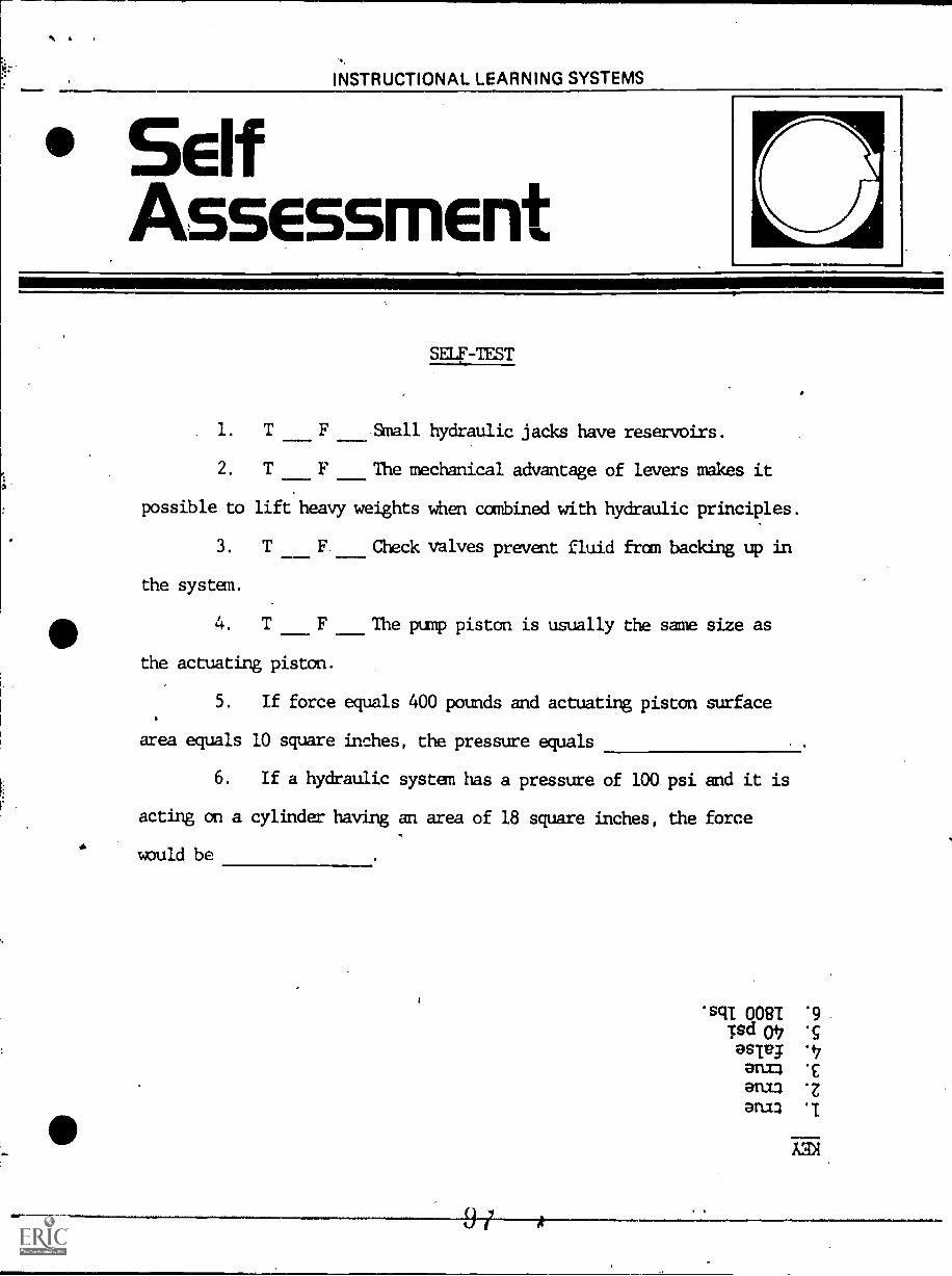
1. T F Small hydraulic jacks have reservoirs.
2. T F The mechanical advantage of levers makes it
possible to lift heavy weights when combined with hydraulic principles.
3. T F Check valves prevent fluid from backing up in
the system.
4. T F The pump piston is usually the same size as
the actuating piston.
5. If force equals 400 pounds and actuating piston surface
area equals 10 square inches, the pressure equals
6. If a hydraulic system has a pressure of 100 psi and it is
acting on a cylinder having an area of 18 square inches, the force
would be
'sclI 0081 '9Tsd 047 5asItg '47
an= cani3 z
arm
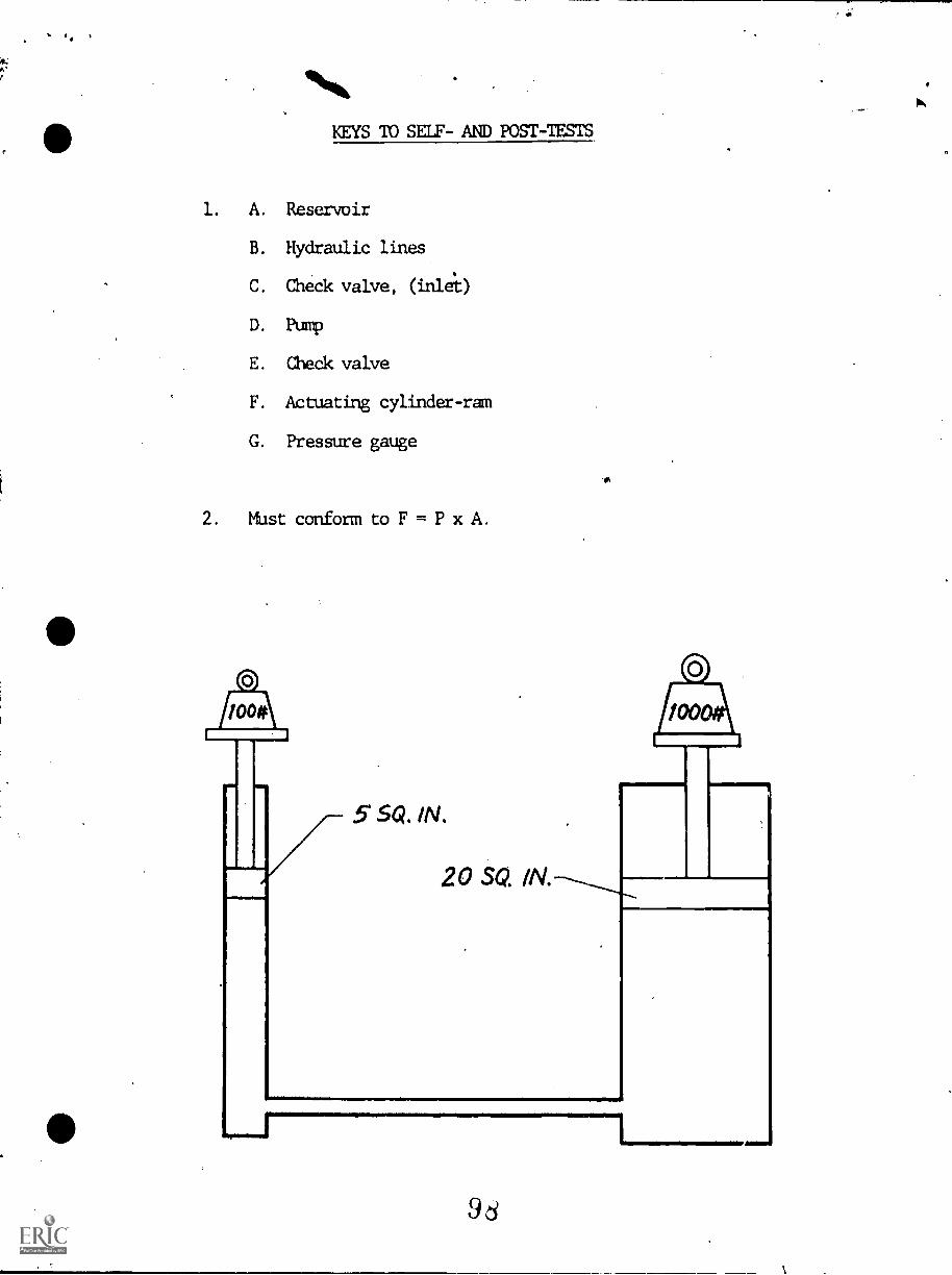
KEYS TO SELF- AND POST-TESTS
1. A. Reservoir
B. Hydraulic lines
C. Check valve, (inlet)
D. Pump
E. Check valve
F. Actuating cylinder-ram
G. Pressure gauge
2. Must conform to F = P x A.
5 SQ. IN.
20 SQ. IN.
9d
INSTRUCTIONAL LEARNING SYSTEMS
° PostAssessment
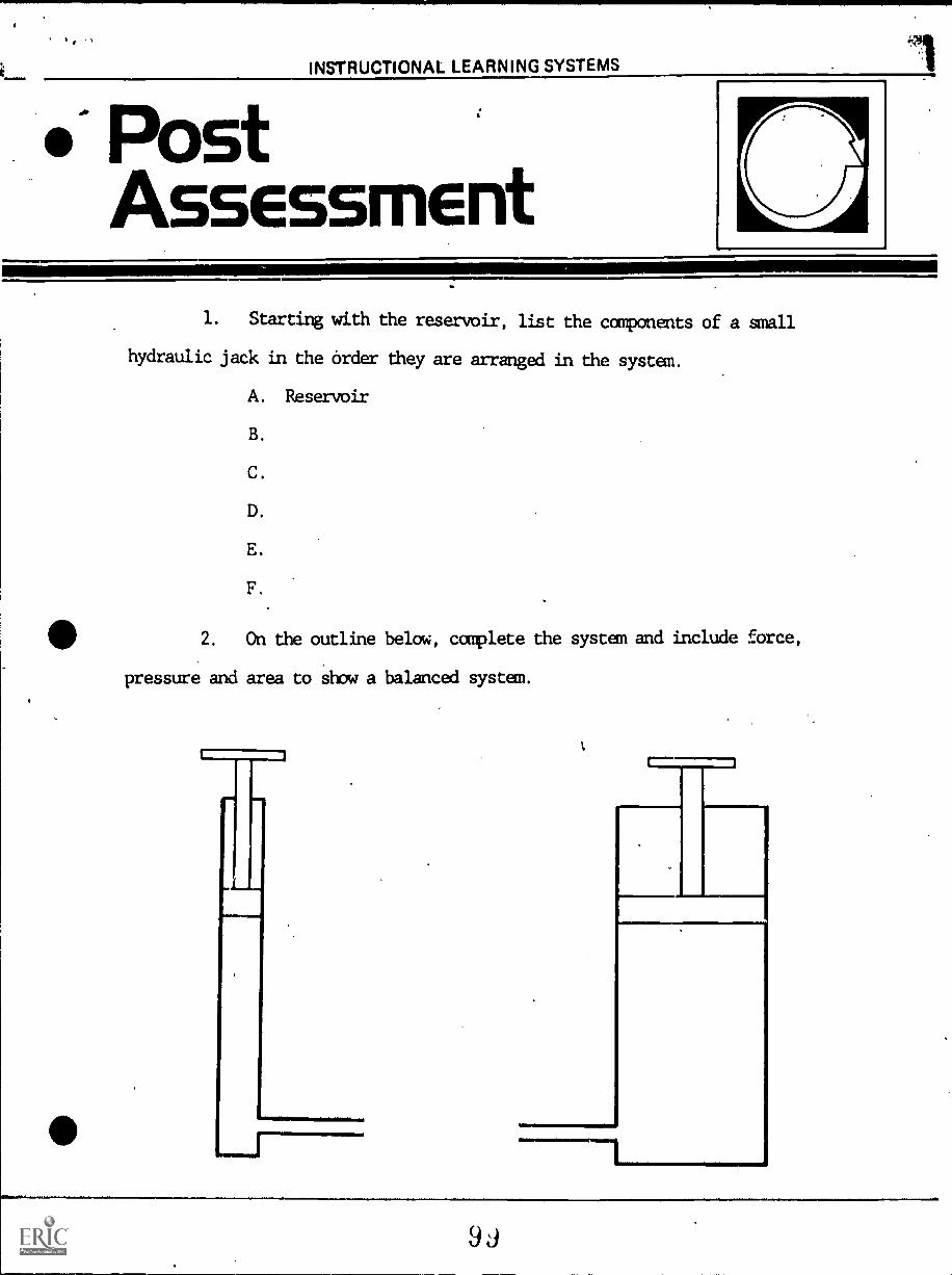
1. Starting with the reservoir, list the components of a small
hydraulic jack in the order they are arranged in the system.
A. Reservoir
B.
C.
D.
E.
F.
411 2. On the outline below, ccaplete the system and include force,
pressure and area to show a balanced system.
r111.11
ir1547410(1A1. LE2t-llirK
Fluid Power
HYDRAULICS
IM-HY-11
Conductors & Connectors
Goal:
The student will know properhydraulic conductor routing andcauses of hose failure.
Performance Indicators:
1. Given a prepared worksheet thestudent will label the correctand incorrect routing of hoses.
2. Given a working hydraulic system,the student will inspect andidentify conductors and hardware.
100
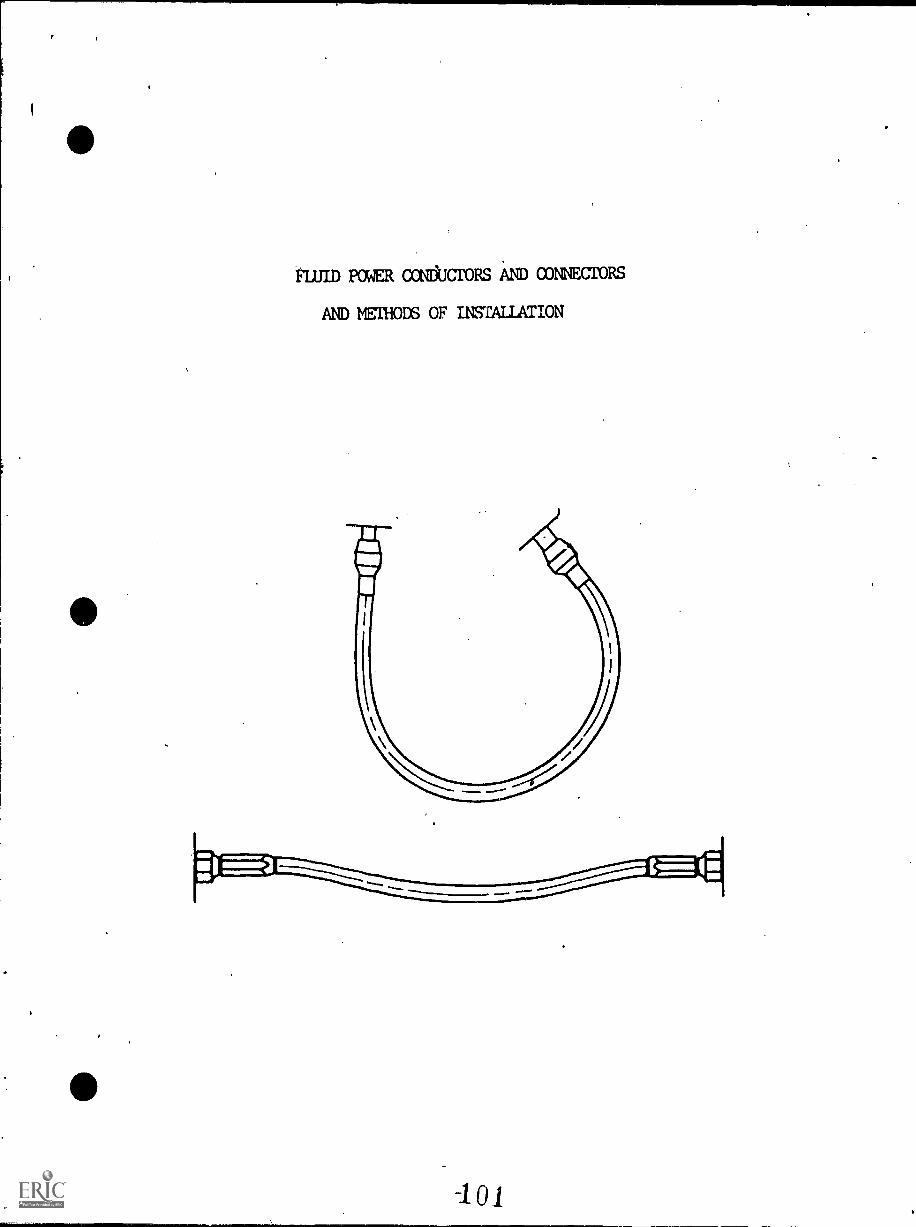
FLUID POWER oomtcroRs AND CONNECTORS
AND METHODS OF INSTALLATION
INSTRUCTIONAL LEARNING SYSTEMS
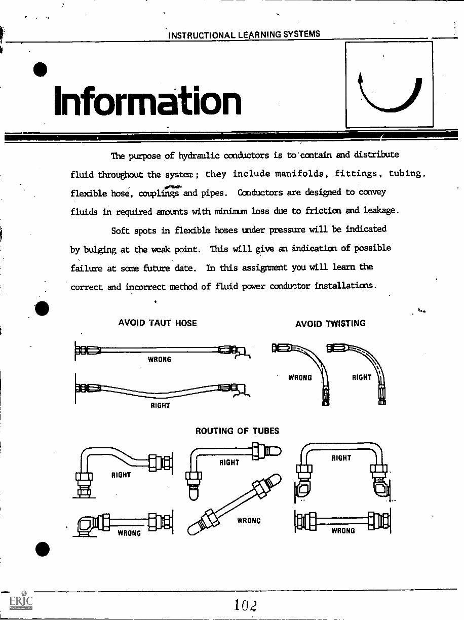
InformationThe purpose of hydraulic conductors is to'contain and distribute
fluid throughout the system ; they include manifolds, fittings, tubing,
ornhop,flexible hose, couplings and pipes. Conductors are designed to convey
fluids in required amounts with minium loss due to friction and leakage.
Soft spots in flexible hoses under pressure will be indicated
by bulging at the weak point. This will give an indicaticn of possible
failure at some future date. In this assignment you will learn the
correct and incorrect method of fluid power conductor installations.
e
AVOID TAUT HOSE
WRONG
RIGHT
ROUTING OF TUBES
WRONG
AVOID TWISTING
WRONG RIGHT
WRONG
102
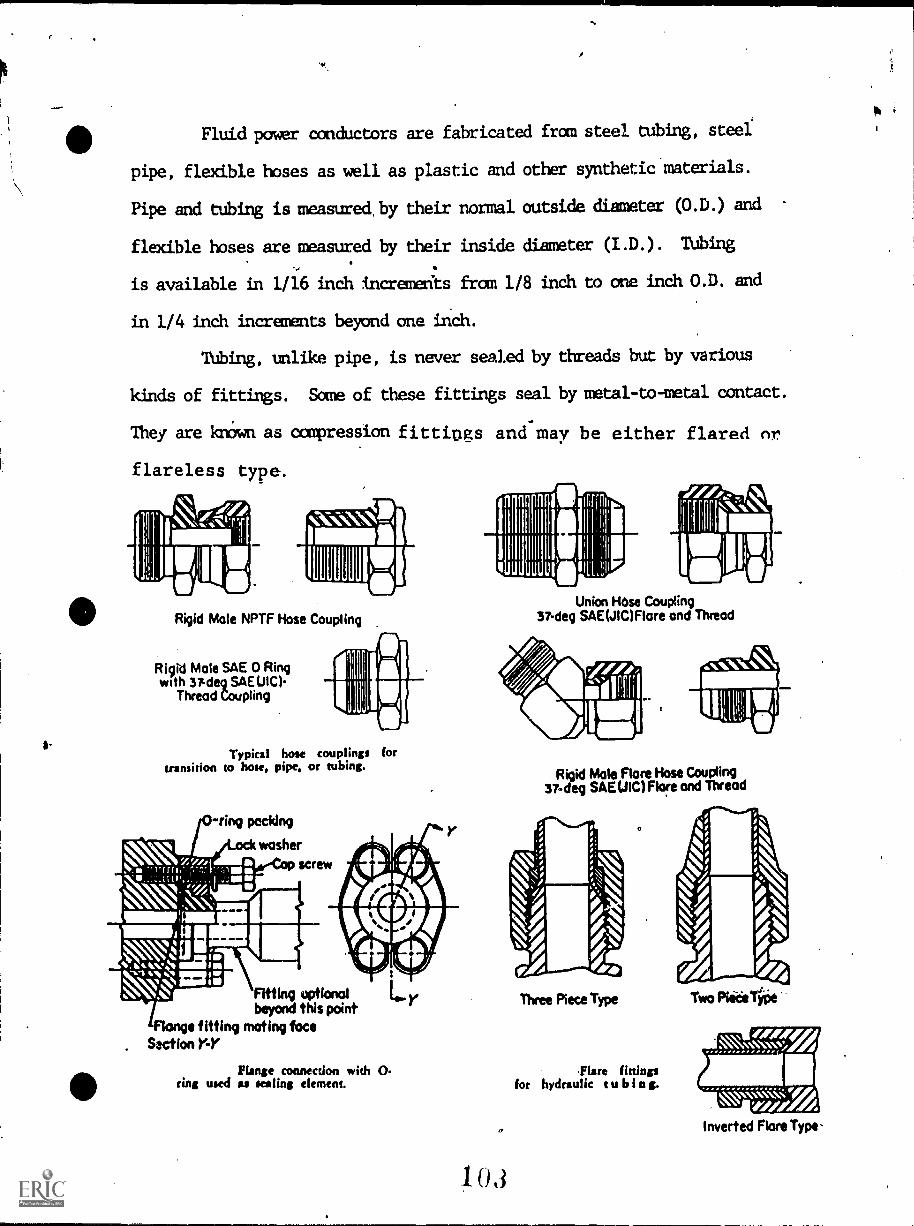
Fluid power conductors are fabricated fran steel tubing, steel
pipe, flexible hoses as well as plastic and other synthetic materials.
Pipe and tubing is measured, by their normal outside diameter (10.D.) and
flexible hoses are measured by their inside diameter (I.D.). TUbing
is available in 1/16 inch incremerits fran 1/8 inch to one inch 0.D. and
in 1/4 inch increments beyond one inch.
Tubing, unlike pipe, is never sealed by threads but by various
kinds of fittings. Some of these fittings seal by metal -to -metal contact.
They are knOwn as compression fittings and may be either flared nr
flareless type.
Rigid Male NPTF Hose Coupling
Rigid Male SAE 0 Ringwith 37-deg SAE Ula
Thread Coupling
Typical hose couplings fortransition to hose, pipe, or tubing.
ring packing
washerscrew
Fitting optionalbeyond this point
e fitting mating faceSaction Y-Y
Plane connection with 0.ring used as sealing element.
103
Union Hose Coupling37-deg SAE(JIC)Flare and Thread
Rigid Male Flare Hose Coupling37-deg SANIC)Flare and Thread
Three Piece Type
'Flare fittingsfor hydraulic tubin g.
Two Pike Type
NNN;;;).N.Inverted Flare Type.
INSTRUCTIONAL LEARNING SYSTEMS
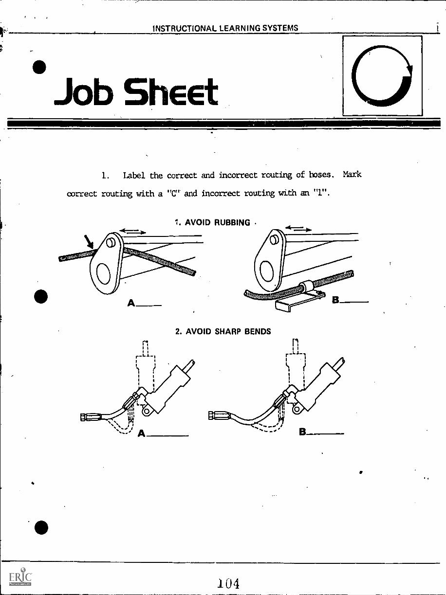
Job Sheet=11.1"
1. Label the correct and incorrect routing of hoses. Mark
correct routing with a "C" and incorrect routing with an "1".
1. AVOID RUBBING
A
r-Ll-
2. AVOID SHARP BENDS
.104
INSTRUCTIONAL LEARNING SYSTEMS
Assignment
LEARNING ACTIVITIES
1. If available, inspect a hydraulic system and with available
references, locate and identify the following fluid power conductors and
connecting hardware:
A. Rigid piping.
B.- Tubing.
C. Flexible hose.
D. Union, hose coupling.
E. Rigid male flare hose coupling.
F. Flange connection.
G. Three piece type flared fitting.
2. If available, use an operating hydraulics system and check
for the following conditions:
A. Fittings for leakage at hydraulics components.
B. Tubing for proper installation.
C. Flexible hoses for kinks or twists. Correct if necessary.
D. Hose not excessively tight (stretched).
105
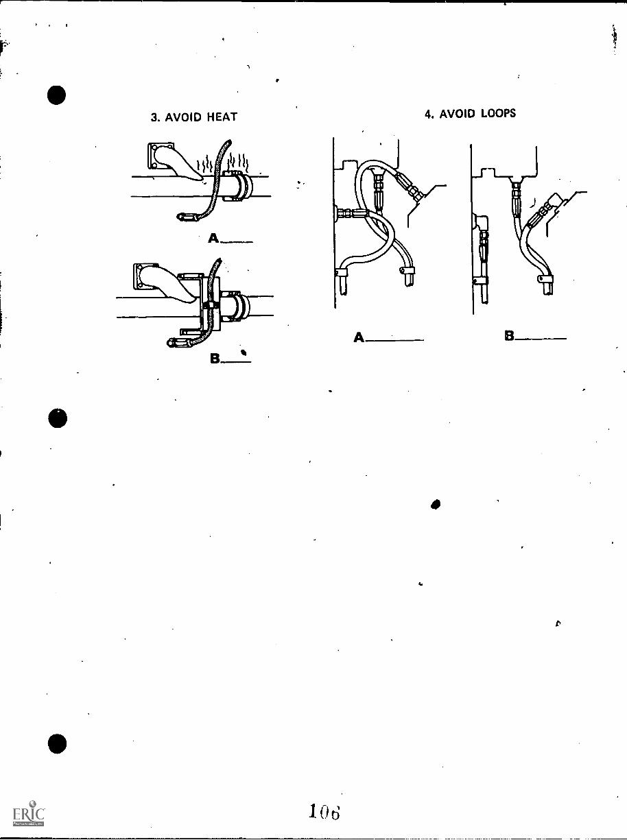
3. AVOID HEAT
B
4. AVOID LOOPS
1 o 6
INSTRUCTIONAL LEARNING SYSTEMS
SelfA smelt
4,amask
SELF-TEST
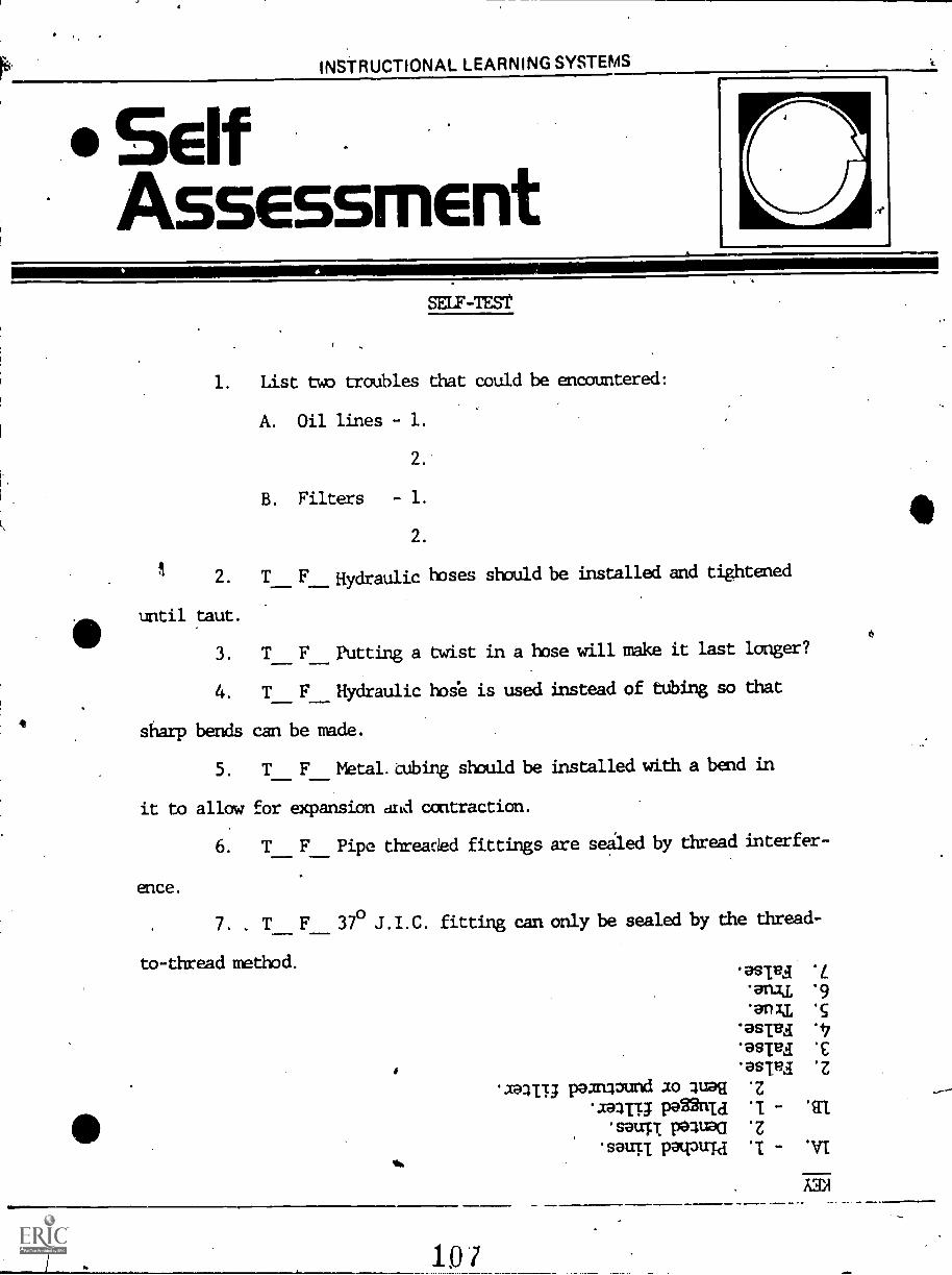
1. List two troubles that could be encountered:
A. Oil lines - 1.
2.
B. Filters - 1.
2.
2. T F Hydraulic hoses should be installed and tightened
until taut.
3. T F Putting a twist in a hose will make it last longer?
4. T Hydraulic hose is used instead of tubing so that
sharp bends can be made.
5. TF Metal. tubing should be installed with a bend in
it to allow for expansion and contraction.
6. T F Pipe threaded fittings are sealed by thread interfer-
ence.
7. . T 37° J.I.C. fitting can only be sealed by the thread-
to-thread method.asieg.ana/ .9
.anu .g
.asredasred E'estRa 'Z
paamound ao 4uaq .z
.aang ponnu .1 .11"
.sauTI Pal ,Q.z
'sauTI PaPuTa 'I "Ol
10
INSTRUCTIONAL LEARNING SYSTEMS
PostAssessment
I
POST -T>
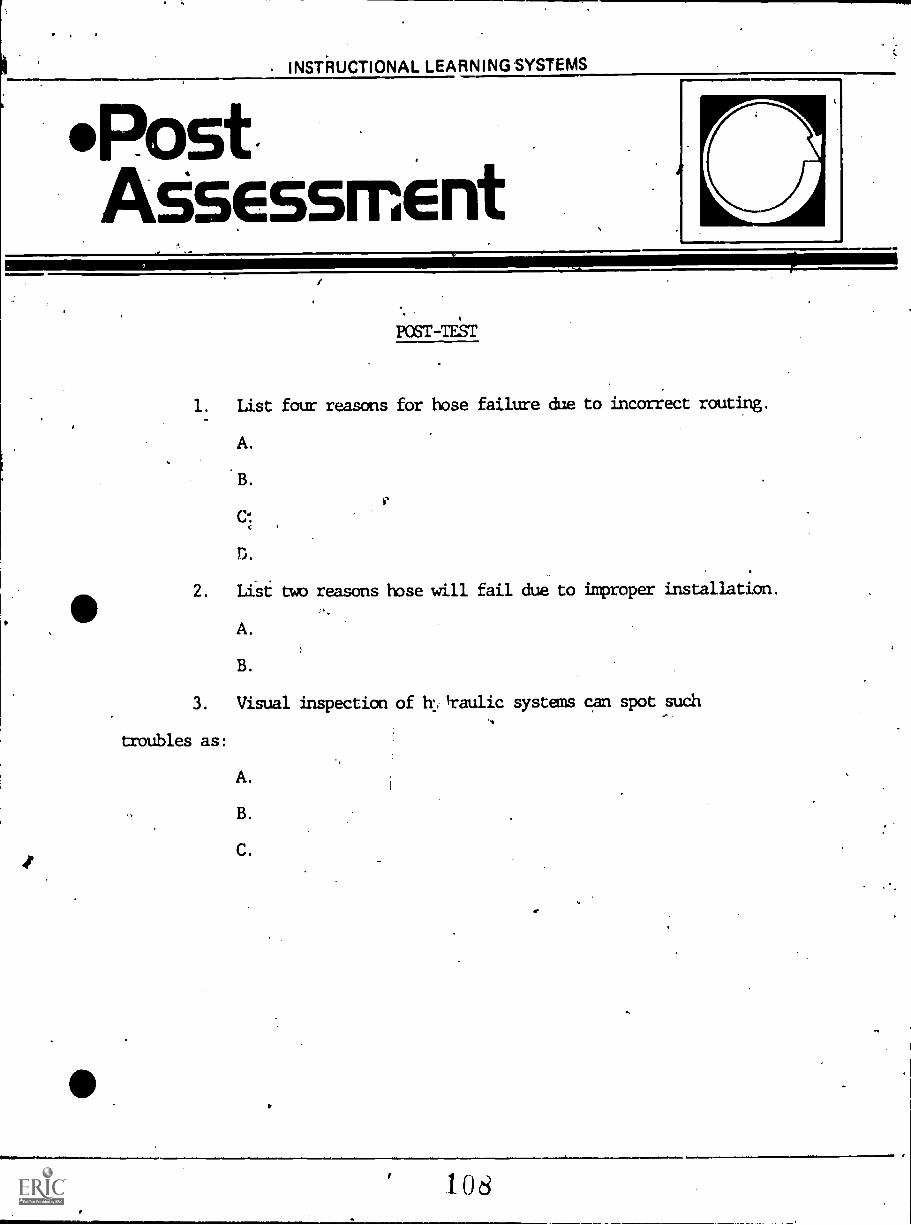
1. List four reasons for hose failure due to incorrect routing.
A.
B.
CI
D.
2. List two reasons hose will fail due to improper installation.
A.
B.
3. Visual inspection of h: itaulic systems can spot such
troubles as:
A.
B.
C.
108
KEY TO POST-TEST
1. A. Rubbing.
B. Sharp bends.
C. Too close to heat.
D. Loops (hoses are too long).
2. A. Too .taut. .
B. Twisted hose.
3. A. Oil leaks.
B. Dirty or plugged filter.
C. Loose connections.
109
HYDRAULICS -- TROUBLESHOOTING
Goal:
The apprentice will be able to describe-troubleshooting procedures for hydraulicsystems.
Performance Indicators:
1. Describe fundamentals of
troublesnooting hydraulics.
2. Describe testing proceduresfor flow, pressure, temperatureand load.
110
1002 -C TROUBLESHOOTING FLUID SYSTEMS
If equipment fails to operate correctly, or ifduring routine maintenance, some flaw in the'equipment is noticed (excessive wear in certainareas or abnormal amounts of oil consumption, etc.),the equipment should he checked to determine the causeof the problem and, if possible, correct the problembefore it becomes a major overhaul. This lessondiscusses some troubleshooting principles and techniques.
111
0
Upon successful completion of this unit, thesvudent will he ahle to:
1. List and discuss four troubleshootingprocedural steps.
2. Describe a procedure for flow, pressure,temperature and load testing, of a fluidpower system.
3. Testa hydraulic pump.
ti
LEARNING ACTIVITIES
ACTIVITIES ,
Read: Information Sheet #1
Read: John Deere Fundamentals of,:Service Hydraulics, chapteron Diagnosis and Testing ofHydraulic Systems
Read: Fluid Power, ,TOFACK DIVISICNGalland-Henning Mfg. Co.,Milwaukee, Wisconsin 53246
PURPOSE
Additional background readingprovides an appreciation,
understanding and other approachesto fluid power systems.
Do: Install a hydraulic tester in To gain experience in testing aa system. Test the pump. piece of fluid power equipment.
INFORMATION SHEET #1
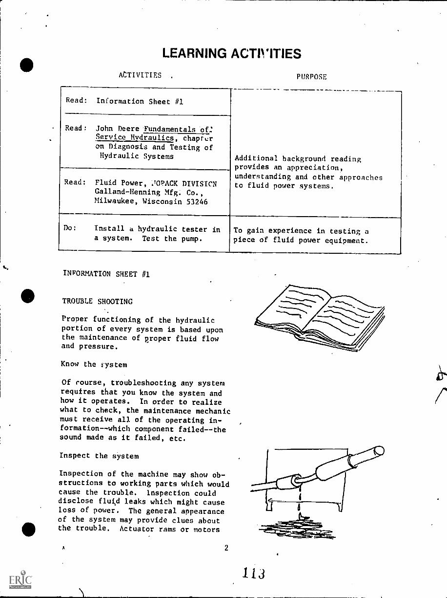
TROUBLE SHOOTING
Proper functioning of the hydraulicportion of every system is based uponthe maintenance of proper fluid flowand pressure.
Know the vystem
Of rourse, troubleshooting any systemrequires that you know the system andhow it operates. In order to realizewhat to check, the maintenance mechanicmust receive all of the operating in-formation--which component failedthesound made as it failed, etc.
Inspect the system
Inspection of the machine may show ob-structions to working parts which wouldcause the trouble. inspection coulddisclose fluid leaks which might causeloss of power. The general appearanceof the system may provide clues aboutthe trouble. Actuator rams or motors
A 2
113
may be bent or damaged. This wouldprevent further start-up.
Run the system
If the unit can function, the mechanicshould start it up, being especially
alert to close down at the first signof trouble that might cause it todamage itself.
Check the system
Since fluid flow and pressure operateevery fluid power system, these shouldbe checked throughout the system. Ifa pump is producing pressure and flow,
it does not necessarily follow that thesame pressure and flow carries through-out the system. In fact, many systemsare designed to provide different pres-sures and flow rates in varying circuitsin the system.
A service manual should be availableto orovide the information for each
scir-uit. The service manual chartswill provide flow and pressure re-quirements at designated locations.
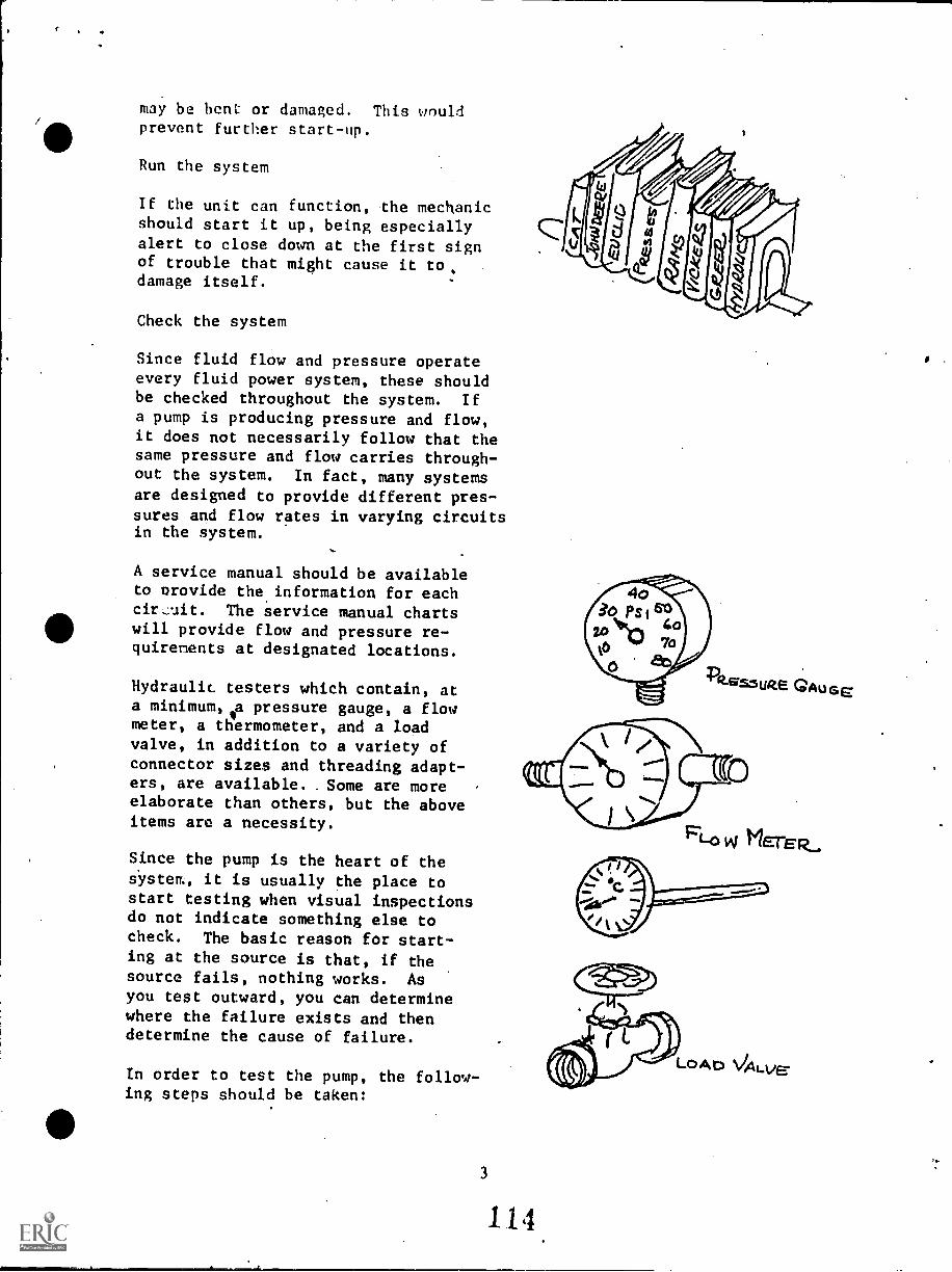
Hydraulic testers which contain, ata minimum, a pressure gauge, a flowmeter, a thermometer, and a loadvalve, in addition to a variety ofconnector sizes and threading adapt-ers, are available.. Some are moreelaborate than others, but the aboveitems are a necessity.
Since the pump is the heart of thesystem, it is usually the place tostart testing when visual inspectionsdo not indicate something else tocheck. The basic reason for start-ing at the source is that, if thesource fails, nothing works. Asyou test outward, you can determinewhere the failure exists and thendetermine the cause of failure.
In order to test the pump, the follow-ing steps should be taken:
3
114
Ft-0 w METER_.
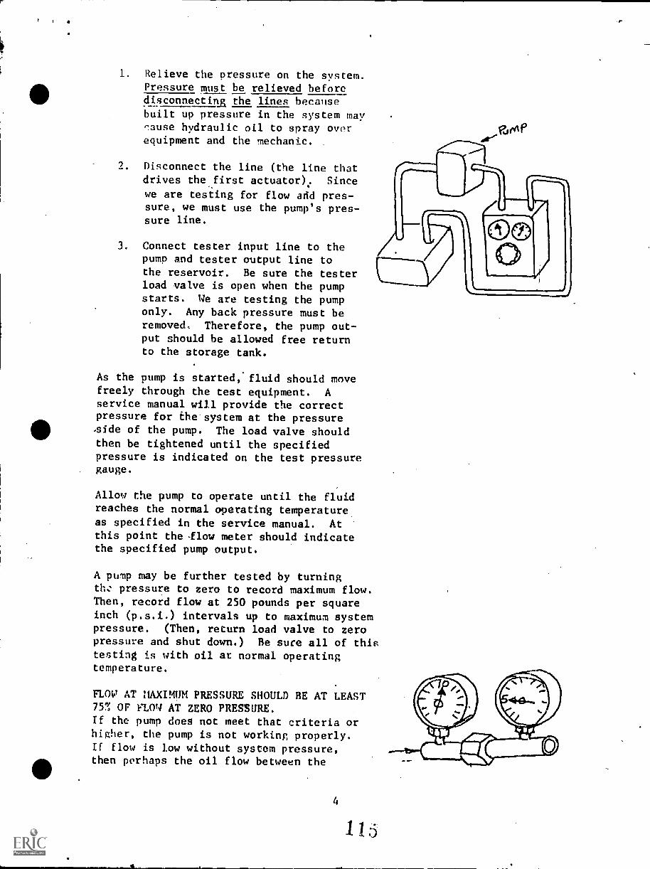
1. Relieve the pressure on the system.Pressure must be relieved beforedisconnecting the lines becausebuilt up pressure in the system may,'.ause hydraulic oil to spray overequipment and the mechanic.
Disconnect the line (the line thatdrives the first actuator).. Since
we are testing for flow add pres-sure, we must use the pump's pres-sure line.
3. Connect tester input line to thepump and tester output line tothe reservoir. Be sure the testerload valve is open when the pumpstarts. We are testing the pumponly. Any back pressure must beremoved, Therefore, the pump out-put should be allowed free returnto the storage tank.
As the pump is started,'fluid should movefreely through the test equipment. Aservice manual will provide the correctpressure for the system at the pressure-side of the pump. The load valve shouldthen be tightened until the specifiedpressure is indicated on the test pressuregauge.
Allow the pump to operate until the fluidreaches the normal operating temperature
as specified in the service manual. Atthis point the low meter should indicatethe specified pump output.
A pump may be further tested by turningth: pressure to zero to record maximum flow.Then, record flow at 250 pounds per squareinch (p.s.i.) intervals up to maximum systempressure. (Then, return load valve to zeropressure and shut down.) Be sure all of thistesting is with oil at normal operatingtemperature.
FLOW AT ItAXIMUM PRESSURE SHOULD BE AT LEAST75% OF FLOq AT ZERO PRESSURE.If the pump does not meet that criteria or
higher, the pump is not working properly.If flow is low without system pressure,then perhaps the oil flow between the
4
1 15
reservoir and the pump is restricted.Sometimes low oil, dirty,filter, restrictedlines, air leaks, dirty breather, Color.ked vent).etc. can cause this problem.
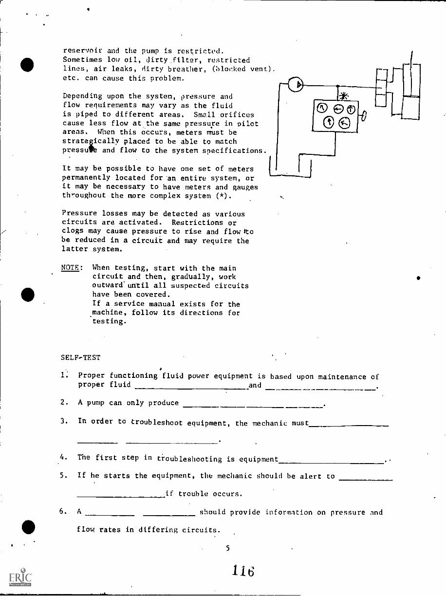
Depending upon the system, pressure andflow requirements may vary as the fluidis piped to different areas. Small orificescause less flow at the same pressure in pilotareas. When this occurs, meters must bestrategically placed to be able to matchpressute and flow to the system specifications.
It may be possible to have one set of meterspermanently located for An entire system, orit may be necessary to have meters and gaugesthroughout the more complex system (*).
Pressure losses may be detected as variouscircuits are activated. Restrictions orclogs may cause pressure to rise and flow ttobe reduced in a circuit and may require thelatter system.
NOTE: When testing, start with the maincircuit and then, gradually, workoutward'until all suspected circuitshave been covered.
If a service manual exists for themachine, follow its directions fortesting.
SELF-TEST
1: Proper functioning fluid power equipment is based upon maintenance ofproper fluid and
2. A pump can only produce
3. In order to troubleshoot equipment, the mechanic must
4. The first step in troubleshooting is equipment
5. If he starts the equipment, the mechanic should be alert to
if trouble occurs.
6. A should provide information on pressure and
flow rates in differing circuits.
5
116
7. Hydraulic testers contain instruments to test_
and
8. Toe first item to he tested is the
9. If a line is to be removed, the first step always is to remove the
10. Flow at maximum pressure should equal at least Z. of flow
at zero pressure if pump is in satisfactory condition.
SL 'CA
aanssaid
&and .9
mou pue 'ainssaid 'aanleiadmal
Ienuum aaTnias
umop lntis
uo-paadsuT
.9
s
ma3sAs atp mom' ec
Z
mou aanssaid
SUMSNIV IS31-.412S
POST-TEST Package Number 1002-c
TROUBLESHOOTTNIC FLUTD SYSTES
Using a standard hydraulic tester, check,prssure and flow at the propertemperature on several circuits of A hydraulic system.
BEST COPY AVAILABLE
118
...
irOCIUMOIIAL likTIT1C0
17.13
HYDRAULICS -- MAINTENANCE
Goal:
The apprentice will be able to describethe fundamentals of maintenance ofhydraulic systems.
AP'
Performance Indicators:
1. Describe four major areas of
concern in routine maintenance.
2. Describe procedures forinspection of hydraulic ramsto determine damage.
3. Describe procedures for
changing oil and filters.
11i
t
Q
of
0a.
1001 -A MAINTENANCE OF FLUID POWER SYSTEMS
Maintenance tasks ar: ti:ose activitiesthat must he don.? .1n a routine basis toprovide the lubrication and upkee7necessary to a smooth operation and longequipment lie,. Well-designed equipmentwill fail prematurely if regular maintenanceis not provided. General maintenanceprocedures are suggested in this learningpackage. Those specific to a particulardevice will be identified in the shopmanual.
120
Upon successful comnletion of thi:i unit,
the scudent will be able to:
1. State four areas of concern: in routine
maintenance.
2. Inspect hydraulic rams for damage.
3. Describe general procedures for changinghydraulic oils, and filter.
ti
121
ACTIVITIES
LEARNING ACTIVITIESPURPOSE
Read: Information ,Sheet ill
Read:1PJoon Deere Fundamentals of .
Service, Hydraulics, GeneralMaintenance
Additional background readingprovides an appreciation andunderstanding as well as other ap-proaches to fluid power systems.
INFORMATION SHEET #1
MAINTENANCE
Once a fluid power system has beencreAted and tested, it should.beable to run fot an extended time.
It is necessary, however, to inspectthe equipment on a periodic basisto discover small problems before.
they become big ones.
It is also necessary to performbasic routine maintenance, such asoil changes, filter changes, systemcleaning and flushing and lineconnection tightness. Where it isPossible, such as on mobile equip-mat, a regular cleaning should bea part of the maintenance pro-
cedures.
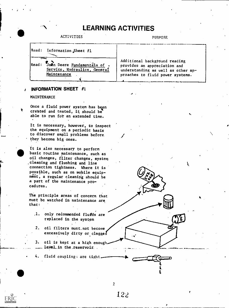
The principle areas of concern thatmust be watched in maintenance arethat:
,l. only recommended fluids arereplaced in the system
2. oil filters must.not become
excessively dirty orclegge
3. oil is kept at a high enoughlee, in the_reservoir. _
4
1
4. fluid coupling.; are
2
122
,A
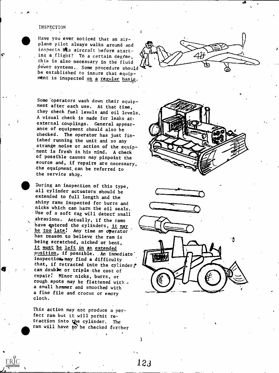
INSPECTION
Have you ever noticed that an air-plane pilot always walks around andinspects 411.s aircraft before start-ing a,flight? TO a certain degfee,this is also necessary in the fluidtioWer systems.. Some procedure shouldbe established to insure that equip-mtnt is inspected on a regular, basis.
Someoperators wash down their equip-ment after each use. At that time,they check fuel levels and oil levels.A visual check is made for leaks at.
external couplings. General appear-.
ance of equipment should also bechecked. The operator has just fin-ished running the unit and so anystrange noise or action of the equip-ment is fresh in his mind. A checkof possible causes may pinpoint thesource and, if repairs are necessary,the equipment, can be referred tothe service shop.
During an inspection of this type,all cylinder actuators should beextended to full length and theshiny rams inspected for burrs andnicks which can harm the oil seals.Use of a soft rag will detect smallabrasions. Actually, if the ramshave entered the cylinders, it an
too. late! Any time an operatorhas reason to believe the ram isbeing scratched, nicked'or bent,It must be left in an extendedposition, if possible. An immediate-inspectionipmay find a difficultythat, if retracted into the cylinder;*can doubhe or triple .the cost ofrepairs Minor nicks, burrs, orrough spots may be flattened with s,
a small hammer and smoothed witha fine file and crocus or emorycloth.
This action may not produce a per-fect ram but it will pefmit re-traction into tke cylinder. Theram will have ,to be checked further
ss
3
123
4
by a mechanic to see if further
the cylinders,
repairs are required. Bent ramsshould be removed from
not retracted into it.
MAINTENANCE ACTIVITIES
Cleanliness:
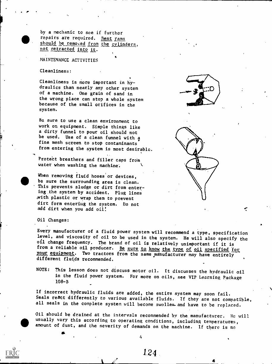
Cleanliness is more important in hy-draulics than nearly any other systemof a machine. One grain of sand inthe wrong place can stop a whole systembecause of the small orifices in thesystem.
Be sure to use a clean environment towork on equipment. Simple things likea dirty funnel to pour oil should notbe used. Use of a clean funnel with Ifine mesh screen to stop contaminantsfrom entering the system is most desirable.
.07
ProteCt breathers and filler caps fromwater when washing the machine.
When removing fluid hoses or devices,be sure the surrounding area is clean.This prevents sludge or dirt from enter-ing the system by accident. Plug lines4with plastic or wrap them to preventdirt form entering the system. Do notadd dirt when you add oil:
Oil Changes:
Every manufacturer of a fluid power system will recommend a type, specificationlevel, and viscosity of oil to be used in the system. He will also specify theoil change frequency. The brand of oil is relatively unimportant if it isfrom a reliable oil producer. Be sure to know, the ,type, of oil specified foryour equipment. Two tractors from the same manufacturer may have entirelydifferent fluids recommended.
NOTE: This lesson does not discuss motor oil. It discusses the hydraulic oilin the fluid power system. For more on oils, see VIP Learning Package108-B
If incorrect hydraulic fluids are added, the entire system may soon fail.Seals react differently to various available fluids. If they are not compatible,all seals in the complete system will become swollen-and have to be replaced.
Oil should be drained at the intervals recommended by the manufacturer. He willusually vary this according to operating conditions, including temperatures,amount of dust, and the severity of demands on the machine. If there is no
ad4
unusually dirty oil in the system, the procedure to follow is:
clean the reservoir
change the filter
replace with approved oil
If the drained oil is particularly,dirty, an approved flush oil may be put intothe system. After the system has Seen operated for a period of rime recom-mended by the manufacturer, the flush oil is drained and the regular oil, andanew filter, may be replaced in the system.
CAUTION: Do not use ordinary cleaning solvents. They do not have proper lu-bricating capabilities, and bearings, surfaces, and seals can be seriouslydamaged.
All drained oil and the bottom of the reservoir should be checked for metalparticles and rubber "chunks".
If these begin to appear, the system should be checked for additional problems.Metal particles usually imply that some unit in the system is failing and themetal, as it rubs against other pieces of metal, is wearing off. It is criticalthat this unit be found as metal particles may get into another unit orvalves and damage the entire system.
Rubber flakes or chunks usually are pieces of "0" rings or hoses that aredeteriorating. As it disintegrates, the.rpbber is carried by the oil streamto the reservoir screen or the oil filter. A failing' hose should be replacedimmediately to avoid a burst hose. A burst hose can cause severe safety haz-ards, such as hot oil on the operator or a critical actuator failing. Failing"0" rings may cause oil leakage.
SELF-TEST
Complete the sentence or circle the most correct answer.
1. Inspection of equipment should be scheduled on a 'basis.
2. Inspections often turn up problems before theybecome major repairs.
3. Four areas of concern are:
4. Extend allspection.
5
125
to full length for in-.
5. Check the above for nicks and burrs which can harm the in
the system.
6. If rams are bent during operation, they must, must not he retracted into
the cylinders.
7. Cleanliness is important becausg of the size of the system's
8. Check with to determine type,
viscosity, specification level of the replacement fluids.
9. Incorrect fluids may cause the to fail.
10. If fluid is excessively dirty, the system may be flushed with
flushing oil.
11. Drained oil should be inspected for particles
and chunks.
aaqqna Telaw 'TT
pattoadde 'OT
sTeas $6
suoT1 eoT3To6de siaa'aropepuew g
aDT3Tao *L
aou 3snw .9
sTeas $g
saoaen3ae aapuTTAo $(7
1112T3 aae Ouridnoo pinTj TanaT Onoua Op' 4e TTo ueaTo4Tquuosuaa aav saalm spTnT3 papuammooaa asn c
6
126
Hews 'Z
avinVaa
1S31.-A13S
g
001POST TEST Package Number l A
MAINTENANCE OF FLUID POWER SYSTEMS
Write a descripticn of a maintenance procedure for fluid power systems.
Be sure to name all of the areas to be included in a proper maintenance
procedure.a
...
CT
v


![Literaturverzeichnis - ULB Bonnhss.ulb.uni-bonn.de/2009/1713/1713-10.pdf · Literaturverzeichnis [Dichmann,ÕÉɃ]Dichmann,D.J.(ÕÉɃ).Hamiltonian Dynamics of a Spatial Elastica](https://img.pdfslide.us/doc/110x75/5d5370c288c9937b448b7068/literaturverzeichnis-ulb-literaturverzeichnis-dichmannoeefdichmanndjoeefhamiltonian.jpg)


![Design Communication [ARC 1713]](https://img.pdfslide.us/doc/110x75/568c4d221a28ab4916a2ca9d/design-communication-arc-1713.jpg)