Embed Size (px)
Citation preview
THURLBY THANDAR INSTRUMENTS
PROGRAMMABLE TRUE RMS MULTIMETER
Model 1705
INSTRUCTION MANUAL

Table of Contents
Introduction 2 Specifications 3 Safety 8 EMC 9 Installation 10 General Operation 12 Making Basic Measurements 16 Dual Measurement Mode 19 Advanced Features 21 Data Logging and Printing 25 Calibration 27 Maintenance 28 Remote Operation 29 Remote Commands 34
General Commands 34 Main Display Commands 35 Dual Measurement Mode Commands 37 First Level Modifier Commands 37 Second Level Modifier Commands 38 Data Logging Commands 40 Calibration Commands 40
Default Settings 41
1
Introduction This programmable true RMS multimeter has dual measurement capability and a dual display † which can show either two independent measurements, a measurement together with its range or a measurement with one of the many calculated functions available.
The key features are:
• Large, high contrast, liquid crystal dual display.
• 0.04% basic accuracy, 12000 counts.
• Manual or autoranging.
• DC and AC Volts, DC and AC current, Resistance, Capacitance, and Frequency measurement; Continuity and Diode checks.
• True RMS AC and AC+DC measurement.
• Display nulling and Ohms null.
• Touch hold mode - holds onto a stable reading until updated.
• 100 point data logger.
• Measurement post-processing to give:
dB and power measurement with settable reference impedance
percentage deviation from a user-entered reference
linear scaling with offset
limits comparison for go/no go testing
automatic storage of minimum and maximum readings.
• Remote control via addressable RS232 (standard) or GPIB (factory-fit option) interfaces.
• Closed case software calibration.
• Fully compliant with EN61010-1 Safety and EN61326 EMC standards.
† Licensed under U.S. Pat. 4,825,392
2
Specifications
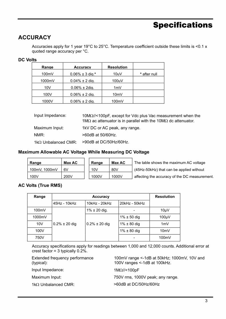
ACCURACY Accuracies apply for 1 year 19°C to 25°C. Temperature coefficient outside these limits is <0.1 x quoted range accuracy per °C.
DC Volts Range Accuracy Resolution
100mV 0.06% ± 3 dig.* 10uV * after null
1000mV 0.04% ± 2 dig. 100uV
10V 0.06% ± 2dig. 1mV
100V 0.06% ± 2 dig. 10mV
1000V 0.06% ± 2 dig. 100mV
Input Impedance: 10MΩ//<100pF, except for Vdc plus Vac measurement when the 1MΩ ac attenuator is in parallel with the 10MΩ dc attenuator.
Maximum Input: 1kV DC or AC peak, any range.
NMR: >60dB at 50/60Hz.
1kΩ Unbalanced CMR: >90dB at DC/50Hz/60Hz.
Maximum Allowable AC Voltage While Measuring DC Voltage
Range Max AC Range Max AC The table shows the maximum AC voltage
100mV, 1000mV 6V 10V 80V (45Hz-50kHz) that can be applied without
100V 200V 1000V 1000V affecting the accuracy of the DC measurement.
AC Volts (True RMS)
Range Accuracy Resolution
45Hz - 10kHz 10kHz - 20kHz 20kHz - 50kHz
100mV 1% ± 20 dig. - 10µV
1000mV 1% ± 50 dig 100µV
10V 0.2% ± 20 dig 0.2% ± 20 dig 1% ± 80 dig 1mV
100V 1% ± 80 dig 10mV
750V - 100mV
Accuracy specifications apply for readings between 1,000 and 12,000 counts. Additional error at crest factor = 3 typically 0.2%.
Extended frequency performance (typical):
100mV range <-1dB at 50kHz; 1000mV, 10V and 100V ranges <-1dB at 100kHz.
Input Impedance: 1MΩ//<100pF
Maximum Input: 750V rms, 1000V peak; any range.
1kΩ Unbalanced CMR: >60dB at DC/50Hz/60Hz
3
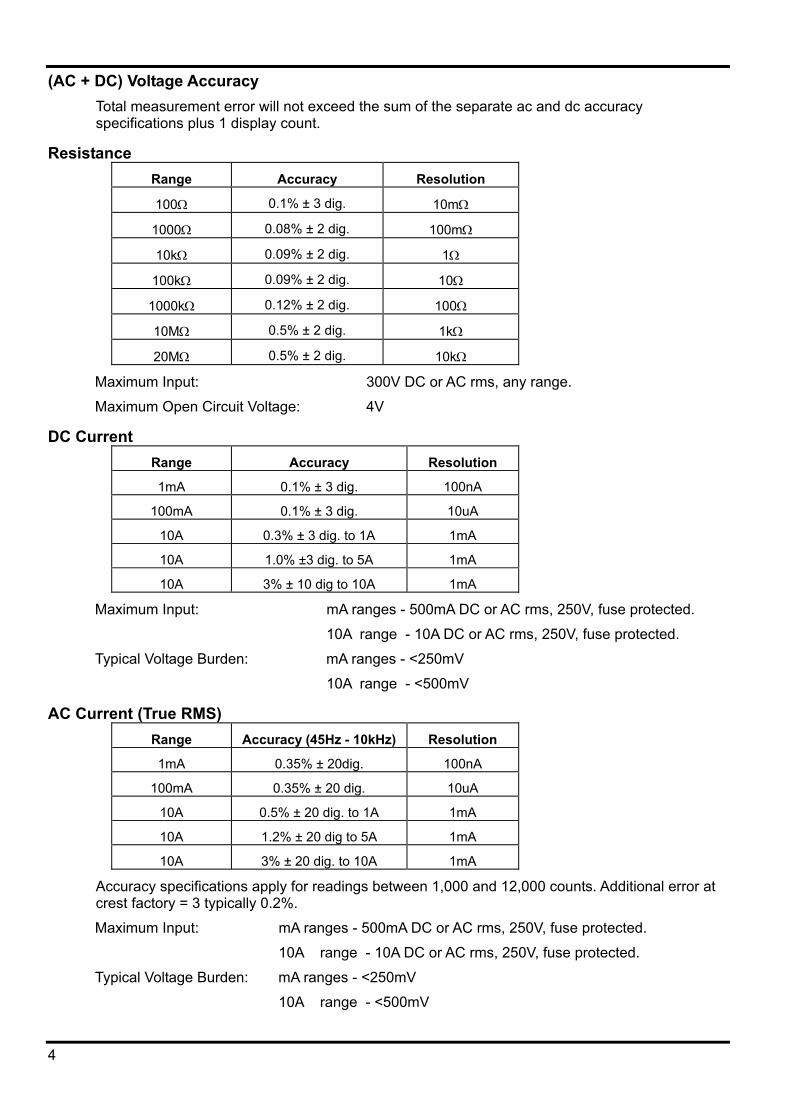
(AC + DC) Voltage Accuracy Total measurement error will not exceed the sum of the separate ac and dc accuracy specifications plus 1 display count.
Resistance Range Accuracy Resolution
100Ω 0.1% ± 3 dig. 10mΩ
1000Ω 0.08% ± 2 dig. 100mΩ
10kΩ 0.09% ± 2 dig. 1Ω
100kΩ 0.09% ± 2 dig. 10Ω
1000kΩ 0.12% ± 2 dig. 100Ω
10MΩ 0.5% ± 2 dig. 1kΩ
20MΩ 0.5% ± 2 dig. 10kΩ
Maximum Input: 300V DC or AC rms, any range.
Maximum Open Circuit Voltage: 4V
DC Current Range Accuracy Resolution
1mA 0.1% ± 3 dig. 100nA
100mA 0.1% ± 3 dig. 10uA
10A 0.3% ± 3 dig. to 1A 1mA
10A 1.0% ±3 dig. to 5A 1mA
10A 3% ± 10 dig to 10A 1mA
Maximum Input: mA ranges - 500mA DC or AC rms, 250V, fuse protected.
10A range - 10A DC or AC rms, 250V, fuse protected.
Typical Voltage Burden: mA ranges - <250mV
10A range - <500mV
AC Current (True RMS) Range Accuracy (45Hz - 10kHz) Resolution
1mA 0.35% ± 20dig. 100nA
100mA 0.35% ± 20 dig. 10uA
10A 0.5% ± 20 dig. to 1A 1mA
10A 1.2% ± 20 dig to 5A 1mA
10A 3% ± 20 dig. to 10A 1mA
Accuracy specifications apply for readings between 1,000 and 12,000 counts. Additional error at crest factory = 3 typically 0.2%.
Maximum Input: mA ranges - 500mA DC or AC rms, 250V, fuse protected.
10A range - 10A DC or AC rms, 250V, fuse protected.
Typical Voltage Burden: mA ranges - <250mV
10A range - <500mV
4
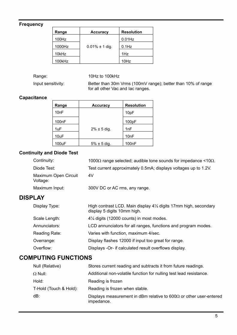
Frequency Range Accuracy Resolution
100Hz 0.01Hz
1000Hz 0.01% ± 1 dig. 0.1Hz
10kHz 1Hz
100kHz 10Hz
Range: 10Hz to 100kHz
Input sensitivity: Better than 30m Vrms (100mV range); better than 10% of range for all other Vac and Iac ranges.
Capacitance Range Accuracy Resolution
10nF 10pF
100nF 100pF
1uF 2% ± 5 dig. 1nF
10uF 10nF
100uF 5% ± 5 dig. 100nF
Continuity and Diode Test Continuity: 1000Ω range selected; audible tone sounds for impedance <10Ω.
Diode Test: Test current approximately 0.5mA; displays voltages up to 1.2V.
Maximum Open Circuit Voltage:
4V
Maximum Input: 300V DC or AC rms, any range.
DISPLAY Display Type: High contrast LCD. Main display 4½ digits 17mm high, secondary
display 5 digits 10mm high.
Scale Length: 4¼ digits (12000 counts) in most modes.
Annunciators: LCD annunciators for all ranges, functions and program modes.
Reading Rate: Varies with function, maximum 4/sec.
Overrange: Display flashes 12000 if input too great for range.
Overflow: Displays -Or- if calculated result overflows display.
COMPUTING FUNCTIONS Null (Relative) Stores current reading and subtracts it from future readings.
Ω Null: Additional non-volatile function for nulling test lead resistance.
Hold: Reading is frozen
T-Hold (Touch & Hold): Reading is frozen when stable.
dB: Displays measurement in dBm relative to 600Ω or other user-entered impedance.
5
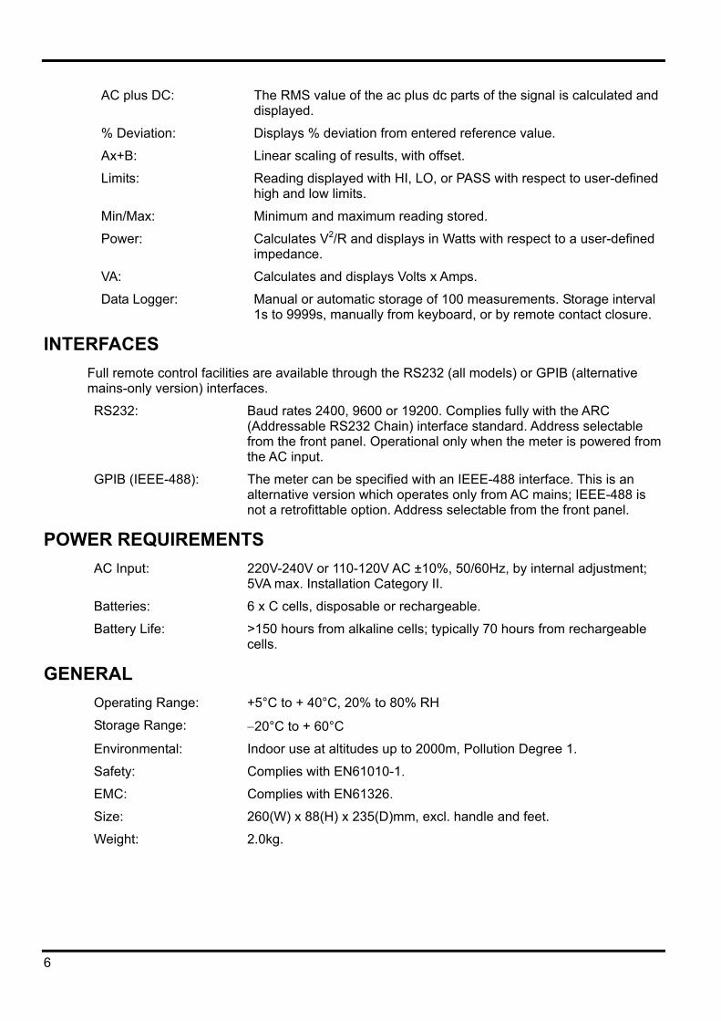
AC plus DC: The RMS value of the ac plus dc parts of the signal is calculated and displayed.
% Deviation: Displays % deviation from entered reference value.
Ax+B: Linear scaling of results, with offset.
Limits: Reading displayed with HI, LO, or PASS with respect to user-defined high and low limits.
Min/Max: Minimum and maximum reading stored.
Power: Calculates V2/R and displays in Watts with respect to a user-defined impedance.
VA: Calculates and displays Volts x Amps.
Data Logger: Manual or automatic storage of 100 measurements. Storage interval 1s to 9999s, manually from keyboard, or by remote contact closure.
INTERFACES Full remote control facilities are available through the RS232 (all models) or GPIB (alternative mains-only version) interfaces.
RS232: Baud rates 2400, 9600 or 19200. Complies fully with the ARC (Addressable RS232 Chain) interface standard. Address selectable from the front panel. Operational only when the meter is powered from the AC input.
GPIB (IEEE-488): The meter can be specified with an IEEE-488 interface. This is an alternative version which operates only from AC mains; IEEE-488 is not a retrofittable option. Address selectable from the front panel.
POWER REQUIREMENTS AC Input: 220V-240V or 110-120V AC ±10%, 50/60Hz, by internal adjustment;
5VA max. Installation Category II.
Batteries: 6 x C cells, disposable or rechargeable.
Battery Life: >150 hours from alkaline cells; typically 70 hours from rechargeable cells.
GENERAL Operating Range: +5°C to + 40°C, 20% to 80% RH
Storage Range: −20°C to + 60°C
Environmental: Indoor use at altitudes up to 2000m, Pollution Degree 1.
Safety: Complies with EN61010-1.
EMC: Complies with EN61326.
Size: 260(W) x 88(H) x 235(D)mm, excl. handle and feet.
Weight: 2.0kg.
6
EC Declaration of Conformity
We Thurlby Thandar Instruments Ltd Glebe Road Huntingdon Cambridgeshire PE29 7DR England
declare that the
Model 1705 True RMS Programmable Multimeter and
Model 1705GP True RMS Programmable Multimeter with GPIB meet the intent of the EMC Directive 89/336/EEC and the Low Voltage Directive 73/23/EEC. Compliance was demonstrated by conformance to the following specifications which have been listed in the Official Journal of the European Communities.
EMC Emissions: a) EN61326 (1998) Radiated, Class B
b) EN61326 (1998) Conducted, Class B
c) EN61326 (1998) Harmonics, referring to EN61000-3-2 (2000)
Immunity: EN61326 (1998) Immunity Table 1, Performance B, referring to:
a) EN61000-4-2 (1995) Electrostatic Discharge
b) EN61000-4-3 (1997) Electromagnetic Field
c) EN61000-4-11 (1994) Voltage Interrupt
d) EN61000-4-4 (1995) Fast Transient
e) EN61000-4-5 (1995) Surge
f) EN61000-4-6 (1996) Conducted RF
Safety Multimeter: EN61010-1 Installation Category I measurements to 1000V, Installation Category II measurements to 600V, Pollution Degree 1.
Probes: IEC1010-2-031 Rated to 1000V, Installation Category III.
CHRIS WILDING TECHNICAL DIRECTOR
2 July 2004
7
Safety This multimeter is a Safety Class I instrument according to IEC classification and has been designed to meet the requirements of EN61010-1 (Safety Requirements for Electrical Equipment for Measurement, Control and Laboratory Use). It is an Installation Category II instrument intended for operation from a normal single phase supply.
WARNING! THIS INSTRUMENT MUST BE EARTHED WHEN OPERATED FROM A MAINS SUPPLY Any interruption of the mains earth conductor inside or outside the instrument will make the instrument dangerous. Intentional interruption is prohibited. The protective action must not be negated by the use of an extension cord without a protective conductor. When operated from the internal batteries the multimeter meets the safety requirements for a Safety Class II (reinforced insulation) product and does not require grounding for safety. The test leads supplied with this instrument meet the requirements of IEC1010-2-031 and are rated to 1000V Cat III; use only these test leads with the meter or a set of equivalent performance. This instrument has been tested in accordance with EN61010-1 and has been supplied in a safe condition. This instruction manual contains some information and warnings which have to be followed by the user to ensure safe operation and to retain the instrument in a safe condition. This instrument has been designed for indoor use in a Pollution Degree 1 environment (no pollution, or only dry non-conductive pollution) in the temperature range 5°C to 40°C, 20% - 80% RH (non-condensing). It may occasionally be subjected to temperatures between +5° and −10°C without degradation of its safety. It has been designed for Installation Category II measurement use to 600VDC/ACrms. and Installation Category I measurement use to 1000VDC/750VACrms. The full definitions of Categories I and II can be found in IEC664, but the following can be taken as a guide: Installation Category I is signal level e.g. telecommunication, electronic equipment, with smaller transient over-voltages than Installation Category II. Installation Category II is local domestic supply level, e.g. portable equipment and appliances. In particular, Category II does not include distribution level supplies, e.g. three phase installations which are classified as Installation Category III. For this equipment 2500V is the maximum peak transient overvoltage that can be tolerated by any terminal with respect to earth ground without impairing safety. Use of this instrument in a manner not specified by these instructions may impair the safety protection provided. Do not operate the instrument outside its rated supply voltages or environmental range. In particular excessive moisture may impair safety. When the instrument is connected to its supply or its inputs are connected to live voltages, terminals may be live and opening the covers or removal of parts (except those to which access can be gained by hand) is likely to expose live parts. The apparatus shall be disconnected from all voltage sources before it is opened for any adjustment, replacement, maintenance or repair. Any adjustment, maintenance and repair of the opened instrument under voltage shall be avoided as far as possible and, if inevitable, shall be carried out only by a skilled person who is aware of the hazard involved. If the instrument is clearly defective, has been subject to mechanical damage, excessive moisture or chemical corrosion the safety protection may be impaired and the apparatus should be withdrawn from use and returned for checking and repair. Make sure that only fuses with the required rated current and of the specified type are used for replacement. The use of makeshift fuses and the short-circuiting of fuse holders is prohibited. Do not wet the instrument when cleaning it and in particular use only a soft dry cloth to clean the display window. The following symbols are used on the instrument and in this manual:
WARNING - risk of electric shock.
mains earth (ground)
CAUTION - refer to accompanying documentation; incorrect operation may damage the meter. direct current
alternating current
8
EMC This instrument has been designed to meet the requirements of the EMC Directive 89/336/EEC.
Compliance was demonstrated by meeting the test limits of the following standards:
Emissions EN61326 (1998) EMC product standard for Electrical Equipment for Measurement, Control and Laboratory Use. Test limits used were:
a) Radiated: Class B
b) Conducted: Class B
c) Harmonics: EN61000-3-2 (2000) Class A; the instrument is Class A by product category.
Immunity EN61326 (1998) EMC product standard for Electrical Equipment for Measurement, Control and Laboratory Use.
Test methods, limits and performance achieved were:
a) EN61000-4-2 (1995) Electrostatic Discharge : 4kV air, 4kV contact, Performance B.
b) EN61000-4-3 (1997) Electromagnetic Field, 3V/m, 80% AM at 1kHz, Performance B.
c) EN61000-4-11 (1994) Voltage Interrupt, 1 cycle, 100%, Performance A.
d) EN61000-4-4 (1995) Fast Transient, 1kV peak (AC line), 0.5kV peak (DC Outputs), Performance B.
e) EN61000-4-5 (1995) Surge, 0.5kV (line to line), 1kV (line to ground), Performance A.
f) EN61000-4-6 (1996) Conducted RF, 3V, 80% AM at 1kHz (AC line only; DC Output connections <3m not tested), Performance A.
According to EN61326 the definitions of performance criteria are:
Performance criterion A: ‘During test normal performance within the specification limits.’
Performance criterion B: ‘During test, temporary degradation, or loss of function or performance which is self-recovering’.
Performance criterion C: ‘During test, temporary degradation, or loss of function or performance which requires operator intervention or system reset occurs.’
Where Performance B is stated the multimeter will continue to function but accuracy may deviate from Specification under the test conditions. However, the possible deviations are small and infrequent and are unlikely to be a problem in practice.
Cautions To ensure continued compliance with the EMC directive the following precautions should be observed:
a) only use screened cables and connectors to connect between the multimeter’s RS232 interface and other equipment.
b) after opening the case for any reason ensure that all signal and ground connections are remade correctly before replacing the cover. Always ensure all case screws are correctly refitted and tightened.
c) In the event of part replacement becoming necessary, only use components of an identical type, see the Service Manual.
9
Installation Mains Operating Voltage
Check that the instrument operating voltage marked on the rear panel is suitable for the local supply. Should it be necessary to change the operating voltage, proceed as follows:
1) Disconnect the instrument from all voltage sources.
2) Unclip the front bezel by gently pulling the centre of each long edge up and forward. The case halves are held together by 4 plastic push-rivets. Use the blade of a small screwdriver in the slot beside each rivet to first ease out the rivet head and then fully remove the rivet body. Separate the case halves. Visit www.tti-test.com for further details.
3) Change the transformer connections following the diagrams below:
4) Reassemble in the reverse order.
5) To comply with safety standard requirements the operating voltage marked on the rear panel must be changed to clearly show the new voltage setting.
Mains Lead When a three core mains lead with bare ends is provided it should be connected as follows:-
Brown - Mains Live
Blue - Mains Neutral Green / Yellow - Mains Earth
WARNING! THIS INSTRUMENT MUST BE EARTHED WHEN OPERATED FROM AN AC LINE SUPPLY
Any interruption of the mains earth conductor inside or outside the instrument will make the instrument dangerous. Intentional interruption is prohibited. The protective action must not be negated by the use of an extension cord without a protective conductor.
Battery Operation To fit or replace the six ‘C’ cells, slide off the battery cover at the rear of the instrument and remove the battery tray. For safety reasons the battery cover can only be slid off after first removing the security screw with a screwdriver. Always refit the security screw after changing the batteries.
10

Either rechargeable or disposable cells may be used; fit into the battery tray observing the polarity marked in the tray. Suitable cells are as follows:
Rechargeable: 2 Amp hour, e.g. NCC200, AN220, VR2C, RSH1.8, P-180C.
Disposable: Alkaline, e.g. MN1400.
Zinc Carbon, e.g. R14B, R14S.
If batteries are fitted it is essential that the disposable/rechargeable selector switch on the rear panel is positioned correctly before applying external power via the AC socket.
WARNING! If disposable batteries are fitted and the selector is set in the rechargeable position, there is a risk of explosion if the meter is connected to an AC supply. The Rechargeable batteries are charged at a ‘trickle’ rate of C/20; the time to fully charge from completely discharged is approximately 28 hours.
Low battery condition is indicated by showing the battery symbol in the top left-hand corner of the display; when this symbol shows, approximately 5% of battery life remains.
11
General Operation This section is a general introduction to the features and organisation of the multimeter intended to be read before using the instrument for the first time. Detailed operation is covered in later sections, starting with Making Basic Measurements.
Connections
Input Sockets The input sockets are 4mm safety sockets on a 19mm pitch designed to accept 4mm safety plugs with fixed or retractable shrouds. The sockets are all rated to 1000V (Cat I)/600V (Cat II) with respect to earth ground.
The input impedance between V/Ω and COM is nominally 10MΩ on dc ranges and 1MΩ on ac ranges. The black COM socket is considered less positive than the red socket.
The mA/10A current sockets are low impedance; the voltage burden between mA/10A and COM at full scale is <250mV for the mA ranges and <500mV for the 10A range. The black COM socket is considered less positive than the white mA/10A sockets.
Multimeter Test Leads
The test leads supplied meet the requirements of IEC1010-2-031 and are rated to 1000V Cat III. Use only the test leads provided, or a set of similar performance, to ensure safe operation. Alternative test leads should be rated to at least 1000V (Cat I), 600V (Cat II) and 10A current capability.
RS232 The RS232 interface only operates when the instrument is run from an ac supply; RS232 signal ground is then connected to the safety ground. The interface is fully isolated from the measurement system.
9-pin D-connector compatible with the Thurlby Thandar ARC (Addressable RS232 Chain) system. The pin connections are shows below:
Pin Name Description 1 - Power to optional PC-02 2 TXD Transmitted data from instrument 3 RXD Received data to instrument 4 - No internal connection 5 GND Signal ground 6 - No internal connection 7 RXD2 Secondary received data 8 TXD2 Secondary transmitted data 9 GND Signal ground
Pin 2, 3 and 5 may be used as a conventional RS232 interface with XON/XOFF handshaking. Pins 7,8 and 9 are additionally used when the instrument is connected to the ARC interface. Signal grounds are connected to safety ground.
To ensure compliance with EMC legislation use only screened cable assemblies with screened connectors when connecting to other equipment.
12
GPIB (IEEE-488) An IEEE-488 interface is available on the alternative mains-only version; IEEE-488 is not a retrofittable option. The GPIB connector is located on the rear panel together with the switch which selects between RS232 and GPIB.
The interface is fully isolated from the measurement system and the GPIB signal grounds are connected to the safety ground. The pin connections are as specified in IEEE std. 488.1-1987.
The implemented subsets are:
SH1, AH1, T8, L4, SR0, RL2, PP0, DC1, DT0 C0, E2
The address is selectable from the front panel.
Switching On
Power Switch The multimeter is switched on and off with alternate presses of the Operate key; this key only switches the DC power to the measurement circuits. It does not switch the AC power, when this is connected, which means that the isolated RS232 and GPIB circuits continue to be powered and rechargeable cells (if fitted) continue to be charged. When the instrument is not in use, and if battery recharging is not required, disconnect from the AC supply.
If the AC supply is removed whilst the meter is switched on one of two things will happen. If the meter had been switched on (with the Operate key) after connection to AC power the meter will automatically power off; if continued operation (from batteries) is required it will be necessary to switch the instrument back on again. In this way the accidental exhaustion of batteries is avoided when AC power is switched off, e.g. when a whole bench of equipment is switched off from a master switch.
However, if the meter had been switched on and run from batteries before the AC power was connected it will continue to run when the AC power is later removed. In this mode the batteries provide back-up in the event of an AC power failure, useful if the meter is “baby-sitting” making, for example, Min-Max measurements over a long time period.
When the instrument is switched on with the Operate key the display first shows all the display segments whilst running an auto-zero routine before setting the operating conditions as described below.
Power-up Settings At power-up the default action is to restore power-down settings, including any modifiers selected at the time that the meter was turned off.
To restore factory default settings (see Default Settings section), hold the Cancel key depressed whilst the meter is turned on with the Operate key; the buzzer will sound to signify that the defaults have been restored.
To review the revision of the installed software hold the Shift key depressed whilst the meter is turned on with the Operate key; the revision will be shown as r x.x until the Shift key is released.
To show all the display segments together (i.e. perform a display test) hold any other key depressed whilst the meter is turned on with the Operate key; the display will continue to show all segments until another key is pressed.
Buzzer A short beep is sounded whenever a valid key is pressed. Longer beeps are reserved to indicate illegal key presses, e.g. selecting Hz in the secondary display when the primary display has been set to Vdc; such keystrokes are not accepted.
13
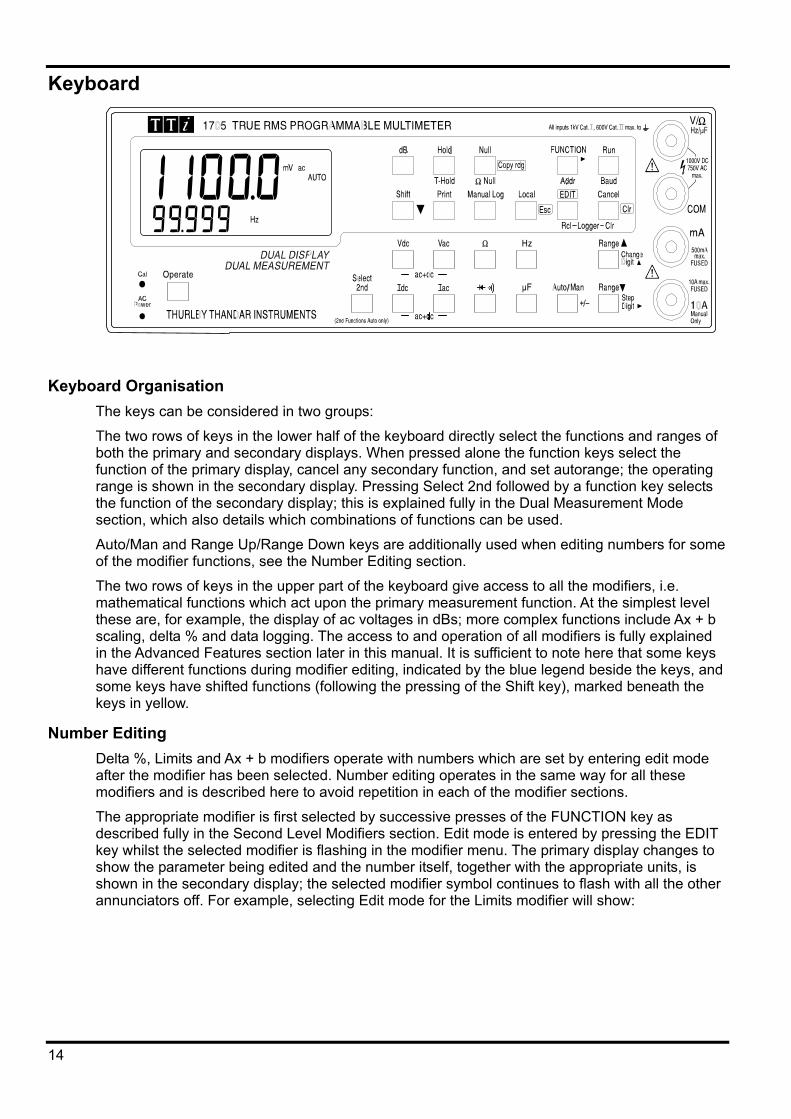
Keyboard
Keyboard Organisation The keys can be considered in two groups:
The two rows of keys in the lower half of the keyboard directly select the functions and ranges of both the primary and secondary displays. When pressed alone the function keys select the function of the primary display, cancel any secondary function, and set autorange; the operating range is shown in the secondary display. Pressing Select 2nd followed by a function key selects the function of the secondary display; this is explained fully in the Dual Measurement Mode section, which also details which combinations of functions can be used.
Auto/Man and Range Up/Range Down keys are additionally used when editing numbers for some of the modifier functions, see the Number Editing section.
The two rows of keys in the upper part of the keyboard give access to all the modifiers, i.e. mathematical functions which act upon the primary measurement function. At the simplest level these are, for example, the display of ac voltages in dBs; more complex functions include Ax + b scaling, delta % and data logging. The access to and operation of all modifiers is fully explained in the Advanced Features section later in this manual. It is sufficient to note here that some keys have different functions during modifier editing, indicated by the blue legend beside the keys, and some keys have shifted functions (following the pressing of the Shift key), marked beneath the keys in yellow.
Number Editing Delta %, Limits and Ax + b modifiers operate with numbers which are set by entering edit mode after the modifier has been selected. Number editing operates in the same way for all these modifiers and is described here to avoid repetition in each of the modifier sections.
The appropriate modifier is first selected by successive presses of the FUNCTION key as described fully in the Second Level Modifiers section. Edit mode is entered by pressing the EDIT key whilst the selected modifier is flashing in the modifier menu. The primary display changes to show the parameter being edited and the number itself, together with the appropriate units, is shown in the secondary display; the selected modifier symbol continues to flash with all the other annunciators off. For example, selecting Edit mode for the Limits modifier will show:
14
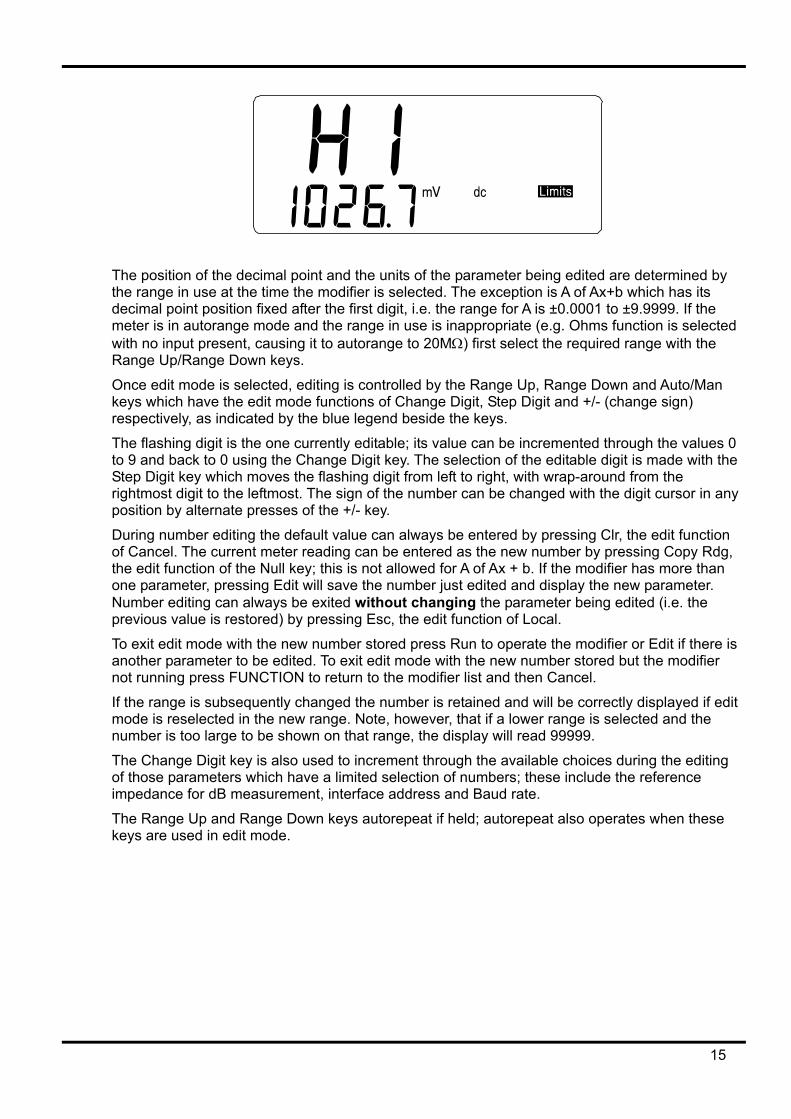
The position of the decimal point and the units of the parameter being edited are determined by the range in use at the time the modifier is selected. The exception is A of Ax+b which has its decimal point position fixed after the first digit, i.e. the range for A is ±0.0001 to ±9.9999. If the meter is in autorange mode and the range in use is inappropriate (e.g. Ohms function is selected with no input present, causing it to autorange to 20MΩ) first select the required range with the Range Up/Range Down keys.
Once edit mode is selected, editing is controlled by the Range Up, Range Down and Auto/Man keys which have the edit mode functions of Change Digit, Step Digit and +/- (change sign) respectively, as indicated by the blue legend beside the keys.
The flashing digit is the one currently editable; its value can be incremented through the values 0 to 9 and back to 0 using the Change Digit key. The selection of the editable digit is made with the Step Digit key which moves the flashing digit from left to right, with wrap-around from the rightmost digit to the leftmost. The sign of the number can be changed with the digit cursor in any position by alternate presses of the +/- key.
During number editing the default value can always be entered by pressing Clr, the edit function of Cancel. The current meter reading can be entered as the new number by pressing Copy Rdg, the edit function of the Null key; this is not allowed for A of Ax + b. If the modifier has more than one parameter, pressing Edit will save the number just edited and display the new parameter. Number editing can always be exited without changing the parameter being edited (i.e. the previous value is restored) by pressing Esc, the edit function of Local.
To exit edit mode with the new number stored press Run to operate the modifier or Edit if there is another parameter to be edited. To exit edit mode with the new number stored but the modifier not running press FUNCTION to return to the modifier list and then Cancel.
If the range is subsequently changed the number is retained and will be correctly displayed if edit mode is reselected in the new range. Note, however, that if a lower range is selected and the number is too large to be shown on that range, the display will read 99999.
The Change Digit key is also used to increment through the available choices during the editing of those parameters which have a limited selection of numbers; these include the reference impedance for dB measurement, interface address and Baud rate.
The Range Up and Range Down keys autorepeat if held; autorepeat also operates when these keys are used in edit mode.
15
Making Basic Measurements This section describes how basic measurements are made, i.e. single measurement mode only and no post-processing of the results.
Scale Length The scale length is ±12000 for all measurements except capacitance (full scale 1200) and the 20MΩ resistance range (full scale 2400).
Function Selection All functions are directly selected by pressing the appropriate function key (Vdc, Ω, Hz, etc.). Changing function always cancels any modifiers already running and sets autorange; providing the appropriate function has been selected (e.g. Ω for resistance measurement) and the parameter to be measured is within the range of the meter, a valid reading should always be shown. The exception is 10A current measurement which requires manual range selection, see next section.
The units and function are shown in the display (e.g. mV dc) together with AUTO to indicate autorange.
When a function is selected in this way the smaller secondary display will show the operating range with units, except for capacitance. If this is not required the secondary display can be turned off by pressing Select 2nd followed by Cancel; the range will be displayed again when the function is next changed, or by pressing Select 2nd twice.
The Continuity/Diode check test key selects continuity test with the first press and then alternates between the modes with further presses. The appropriate annunciator indicates the current selection. Continuity sets the meter to the 1000.0Ω range and buzzes for values below approximately 10Ω.
Vdc+Vac or Idc+Iac measurements are made by pressing both Voltage range or both current range keys together. The reading displayed is the RMS sum √(dc2 + ac2) and ac+dc is shown beside it. Both ac and dc measurements are made on the same range: the instrument will autorange to a range which gives an in-range reading for both the ac and dc component of the parameter. However, if the result exceeds the range maximum the meter will autorange up to permit the result to be shown as an in-range reading.
Range Selection Selecting a new function always sets autorange to ensure an in-range reading is made with maximum resolution whenever possible; the meter ranges up at 12000 counts and ranges down at 1000 counts.
There are, however, situations when it is desirable to lock the range; for example, to stop the meter autoranging to the 20MΩ range and back between successive resistance measurements of lower resistance values, or to set a lower resolution range when an unstable parameter is being monitored. To lock the range, change from auto to manual ranging, see below.
Manual range changing is selected either by alternate presses of the Auto/Man key, which locks the meter in its present range, or by using the Range Up/Range Down keys which both change the range and lock the meter in that new range. The MAN annunciator is displayed to indicate manual ranging. Overrange is indicated by flashing the display at 12000 counts. Autoranging can be restored by pressing the Auto/Man key again.
As explained later in the appropriate sections, secondary functions in dual measurement mode are autoranging only; the exception is 10A range selection which is manual only, for both main and secondary displays, at all times.
16
Making Voltage Measurements Voltage measurements are made using the red V/Ω socket and the black COM socket having selected the appropriate function and range as described above.
The meter will show a minus sign (on dc measurements) when the voltage applied to the red socket is more negative than that applied to the black socket.
The maximum voltage that can be applied between V/Ω and COM is 1000V DC or 750V AC (Cat I); damage to the instrument may result if this limit is exceeded.
WARNING! The maximum input voltage to ground must not exceed 1000V (Cat I) or 600V (Cat II) dc or ac rms. Safety will be impaired if these ratings are exceeded, see Safety section at the beginning of the manual.
Making Current Measurements Having selected the appropriate current function, current measurements up to 120mA are made using the white mA socket and the black COM socket; current measurements up to 10A are made using the 10A and COM socket. The meter will show a minus sign (on dc measurements) when the polarity of the current is out of the mA or 10A sockets.
Current measurements using the mA socket can be autoranged between 1.0000 mA and 100.00mA ranges; measurements up to 10A can be made using the 10A socket having manually ranged to 10A with the Range Up key.
The 1mA and 100mA ranges, using the mA socket, are protected by a 500mA (F) HBC fuse and the 10A range, using the 10A socket, is protected by a 10A (F) HBC fuse. Both fuses are fitted inside the instrument and replacement is described in the Maintenance section later in the manual.
Note: After measuring high current using the 10A input, thermal voltages are generated that may create errors when making measurements on the most sensitive dc voltage, current or Ohms ranges immediately afterwards. To ensure that the specified accuracy is maintained, allow 10 minutes for the thermal effects to fade before making sensitive measurements.
Making Resistance Measurements Resistance measurements are made using the V/Ω and COM sockets. Residual test lead resistance can be nulled out using the Ohms null facility as follows:
Connect the test leads together and press Shift, Null (Ω Null is the shifted function of Null). The 100Ω range is set automatically and the NULL annunciator flashes; the meter stores the reading that it detects after 5 seconds provided that it is less than 1.00Ω (100 counts). A beep sounds when the null is completed and the display should show zero Ohms and no NULL annunciator; the meter returns to its previous range, or AUTO if autorange had been operational before Ohms null was selected.
If the reading cannot be nulled, because the offset is too large, the reading will not change and the buzzer will not sound.
The Ohms null is stored as a floating point value which is used on all ranges; it is not lost when the function is changed or when the instrument is turned off. Ohms null can be cancelled by either pressing the Ω and Cancel keys together, by selecting Ohms Null and not generating a sub 1.00Ω reading within the next 5 seconds, or by holding the Cancel key down at power-up to restore the system defaults.
Normal Null can be used together with Ohms Null.
17
Making Continuity and Diode Checks Continuity and diode checks are made using the V/Ω and COM sockets.
Pressing the Continuity/Diode check key selects Continuity mode with the first press; the continuity indicator is shown in the display. The 1000Ω range is selected and readings below approximately 10Ω sound the continuity buzzer.
A further press selects diode check; the diode annunciator is shown in the display. The 1000mV range is selected and the approximate diode voltage at 0.5mA is shown (1.2V maximum). Reverse diode connection will show overload.
Further presses of the key will alternate between Continuity and Diode check.
Making Capacitance Measurements Capacitance measurements are made using the V/Ω and COM sockets. Capacitance measurement is selected by pressing the µF key. Five ranges (10nF to 100µF) are available with 1200 count full scale giving resolutions of 10pF to 100nF respectively.
Zero calibration at the factory is carried out with no test leads connected; ideally, capacitors to be measured should be connected directly to the sockets. Test leads, if used, should be kept as short as possible to minimise stray capacitance but nevertheless a non-zero reading will generally be present when the lowest ranges are selected. To eliminate this offset it is recommended that the meter reading is nulled, once the require range has been selected, with the test leads in their measurement positions but no capacitor connected. It is also recommended that battery operation is used when making capacitance measurements, to minimise reading jitter. Note that because the capacitor is discharged between each measurement, the reading rate on the 100µF range is slower.
Making Frequency Measurements Frequency measurements are made using the V/Ω and COM sockets.
Press the Hz key to select frequency mode. Four ranges (100Hz to 100kHz) are available giving resolutions of 10mHz to 10Hz respectively over an operating frequency range of 10Hz to 120kHz. Reciprocal counting techniques ensure fast reading updates (4 readings/second) even on the lowest range.
Measurements are made using the ac Volts input circuitry which is autoranged to provide suitable sensitivity. At low signal levels use a screened lead and an adaptor (BNC to 4mm plugs, 19mm pitch) to preserve signal quality and avoid spurious readings from stray pick-up. The minimum measurable signal is typically <30mV rms across the frequency range.
Frequency can also be measured in dual measurement mode, see next section. When measuring the frequency of an ac current the minimum measurable signal is typically <10% of range maximum, e.g. <0.1mA on the 1mA range.
Zero Calibration An automatic zero calibration of the basic DC measurement circuitry is performed every time that the instrument is switched on. However, if the meter has been stored at a temperature outside the specified operating range, and is switched on before it has fully acclimatised to the working environment, accuracy may be affected as the meter’s temperature changes. To ensure optimum accuracy, particularly on the 100mV and mA current ranges, zero calibration can be repeated when the meter has acclimatised by using the Null key as follows:
Press the Null key and continue to hold it down until nULL shows in the main display (about 3 seconds later). nULL continues to show whilst the auto-zero is being performed (typically 5 seconds); on completion the display returns to it previous mode.
Auto-zeroing in this way cancels Null if this was already selected; press Null again to re-select if required.
18
Dual Measurement Mode In Dual Measurement Mode a completely independent but complementary measurement can be made and displayed on the secondary display. The two independent measurements are actually made alternately, not simultaneously, and the display update rate for each measurement is consequently reduced. Note that this is not the same as when, in dual display mode, both a measurement and a modified version of that measurement are displayed, e.g. ac Volts and the dB equivalent; in this case only a single measurement is being made and the measurement rate is unchanged; further information is given later in this section.
Dual Measurement Combinations All practical combinations of functions are allowed in Dual Measurement Mode; those of no practical use (e.g. dc Volts and Frequency) are not selectable. The full list is as follows:
Main Display Secondary Display Vdc Vac, Idc, Iac
Vac Vdc, Idc, Iac, Hz
Idc Vdc, Vac, Iac
Iac Vdc, Vac, Idc, Hz
Hz Vac, Iac
Capacitance, Ω, and Continuity/Diode check cannot meaningfully be combined with other measurements and are therefore always excluded from the secondary display. Vac+Vdc and Iac+Idc are also excluded because they already involve dual measurements; when they are being used no secondary display can be set.
The same measurement can be displayed in both displays, if required, at the single measurement update rate; in this mode the displays both use the range set for the main display.
The secondary display is selected by pressing Select 2nd followed by the function; pressing an illegal function will cause a warning beep and the key entry will be ignored. Pressing Select 2nd twice will return the meter to single measurement mode with the range shown in the secondary display; pressing Select 2nd followed by Cancel turns the secondary display off. Selecting any main display function will also return the meter to single measurement mode.
The secondary measurement, with the exception of the 10A current ranges, always autoranges. The 10A current ranges are set by first selecting the function (Select 2nd followed by Iac or Idc) then pressing Select 2nd followed by Range Up; return to the mA autoranges is by pressing Select 2nd followed by Range Down. However, if both main and secondary displays are making current measurements, the range of the secondary measurement is always that of the main display.
If Vdc and Vac are the two measurement functions, autoranging of the secondary display is restricted such that the dc measurement range is not lower than the ac range; this ensures that the dc measurement is not affected by a high ac signal, see the table in the Specification (page 3). For example, if the main display is set to 10Vdc the secondary display can autorange between the 100mV, 1000mV and 10Vac ranges. In this example, low levels of ripple could be measured (on the 100mV range) on a 10Vdc supply rail, but an ac input >12V will cause the secondary display to flash 12000 (overload) warning the user to select a higher main display dc range such that the secondary ac measurement is in range. Similarly, if the main display is set to 100Vac then the secondary display will not autorange below 100Vdc, even for small dc inputs.
When frequency is selected for the secondary display the measurement is made using the ac range set in the main display. This presents no problems if the main display is in autorange but if a higher range has been set manually, such that the reading is less than 10% of the range maximum, the signal level may not be adequate for frequency measurement.
19
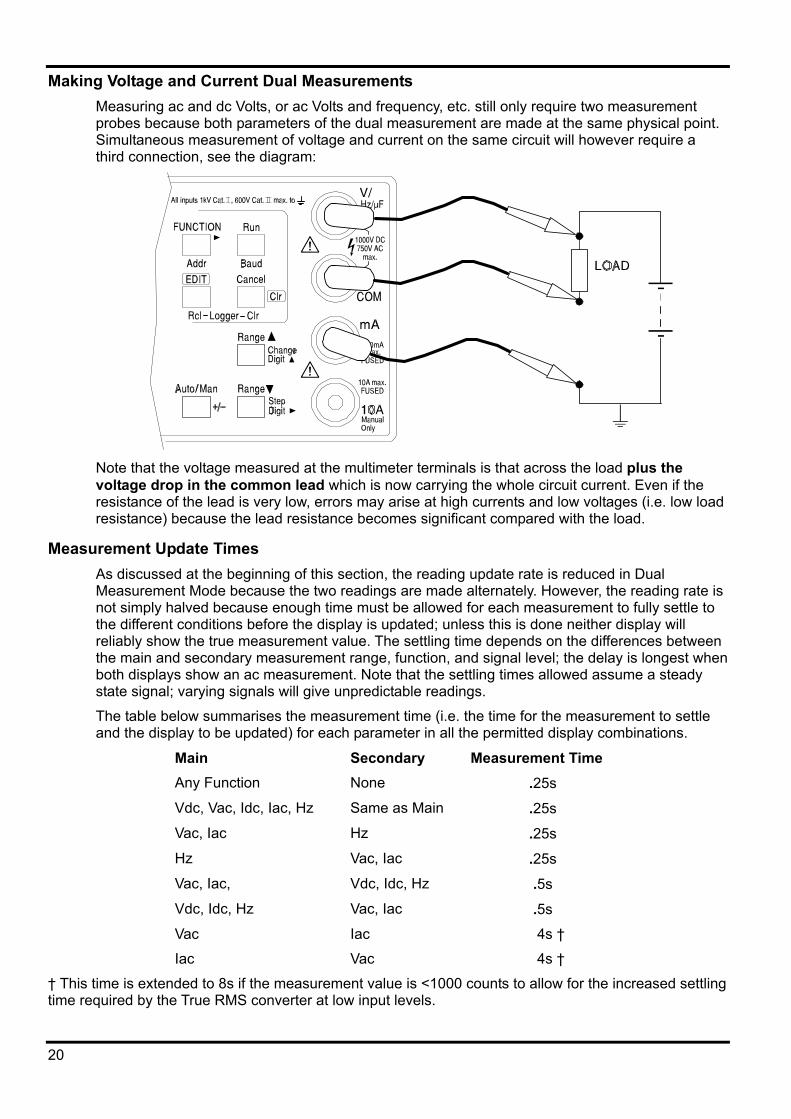
Making Voltage and Current Dual Measurements Measuring ac and dc Volts, or ac Volts and frequency, etc. still only require two measurement probes because both parameters of the dual measurement are made at the same physical point. Simultaneous measurement of voltage and current on the same circuit will however require a third connection, see the diagram:
Note that the voltage measured at the multimeter terminals is that across the load plus the voltage drop in the common lead which is now carrying the whole circuit current. Even if the resistance of the lead is very low, errors may arise at high currents and low voltages (i.e. low load resistance) because the lead resistance becomes significant compared with the load.
Measurement Update Times As discussed at the beginning of this section, the reading update rate is reduced in Dual Measurement Mode because the two readings are made alternately. However, the reading rate is not simply halved because enough time must be allowed for each measurement to fully settle to the different conditions before the display is updated; unless this is done neither display will reliably show the true measurement value. The settling time depends on the differences between the main and secondary measurement range, function, and signal level; the delay is longest when both displays show an ac measurement. Note that the settling times allowed assume a steady state signal; varying signals will give unpredictable readings.
The table below summarises the measurement time (i.e. the time for the measurement to settle and the display to be updated) for each parameter in all the permitted display combinations.
Main Secondary Measurement Time Any Function None .25s
Vdc, Vac, Idc, Iac, Hz Same as Main .25s
Vac, Iac Hz .25s
Hz Vac, Iac .25s
Vac, Iac, Vdc, Idc, Hz .5s
Vdc, Idc, Hz Vac, Iac .5s
Vac Iac 4s †
Iac Vac 4s †
† This time is extended to 8s if the measurement value is <1000 counts to allow for the increased settling time required by the True RMS converter at low input levels.
20
Advanced Features The advanced features of this multimeter are all accessed using the keys in the top two rows of the keyboard. Broadly, they divide into First Level Modifiers which are accessed via dedicated keys (dB, Hold and Null) and Second Level Modifiers which are all accessed from a menu using the FUNCTION modifier key.
All modifiers are post-processors of some sort which act on the basic measurement to produce a modified result. Most modifiers make use of the secondary display to show either the modified results with the actual reading in the main display, or vice-versa; consequently Dual Measurement Mode is not allowed when running any of the modifiers. Selecting any modifier cancels Dual Measurement Mode.
First Level Modifiers The following modifiers are selected directly using a dedicated key.
Hold Pressing Hold freezes the main display and shows the HOLD annunciator. The normal, updated, reading will be shown in the secondary display if the meter is not in dual measurement mode, except for capacitance. Hold does not operate on the secondary display.
Hold can be used with dB and Null. Hold is cancelled by pressing Hold again or by changing range or function.
T Hold T Hold is selected by pressing Shift then T-Hold (the shifted function of Hold); T-HOLD shows in the display. In this mode the meter will hold a reading until a new non-zero measurement has been detected; this allows the user to touch-probe the measurement point, remove the probes and read the meter afterwards. Note, however, that care should be taken when using T-Hold with the most sensitive voltage ranges; when the probes are lifted from the circuit being measured, their high impedance means that stray pick-up might generate another ‘valid’ reading and the true T-Hold reading may be lost.
T-Hold operates in both manual and autorange modes; it is cancelled by pressing Hold again or by changing function.
Null Null is selected by pressing the Null key. Pressing Null locks the meter in the selected range, shows NULL and MAN in the display, stores the current reading and subtracts it from all following readings. The normal, un-nulled, reading will be shown in the secondary display if the meter is not in dual measurement mode, except for capacitance.
Null can be used with Hold. Null is cancelled by pressing Null again or by changing range or function.
dB dB (deciBel) can be selected only when Vac is already in the main display. Pressing dB shows the dB value of the Vac measurement (referred to the current impedance setting) and displays the dB annunciator. dBs are shown in a fixed format with 0.1dB resolution, whatever range the Vac measurement is being made on. If no secondary function is selected the normal reading will be shown in the secondary display.
The value displayed is in dBm and is calculated from the formula:
dB = 10 log10 (1000 x V2/R)
Where R is the selected reference impedance.
21
The default reference impedance is 600Ω but a different value can be selected by entering the edit mode. With dB already selected press EDIT; the main display will now show rEF and the current impedances will be shown in the secondary display. Use the Range Up/Range Down keys to scroll through the list of impedances which can be set:
50, 75, 93, 110, 124, 125, 135, 150, 250, 300, 500, 600, 900, 1000, 1200, and 8000Ω. Pressing Clr, the edit function of Cancel, enters the default value of 600Ω. To exit edit mode saving the new reference impedance press Run or dB; to exit edit mode without changing the value (i.e. the previous value is restored) press Esc.
Hold can be used with dB mode, but selecting any other function will cancel dB; pressing dB again will also cancel it.
Second Level Modifiers Second level modifiers are mutually exclusive; selecting a second level modifier cancels any previous one. Selecting a second level modifier cancels Dual Measurement Mode. Pressing Cancel, or changing the function or range, will cancel the modifier but the parameter values are saved.
Selection and Editing All modifiers are selected by pressing the FUNCTION key. The first press shows all the available modifiers as a ‘menu’ with the last-selected one flashing. Subsequent presses of FUNCTION make each modifier flash in turn; the current selection is the flashing one.
To run the selected modifier press Run at this point; the flashing modifier symbol is now static and all the other modifiers annunciators are off. When running, the modified value appears on the secondary display; the main display continues to show the un-modified value. Pressing Cancel during modifier selection, or while a modifier is running, cancels the modifier and returns the meter to single measurement mode.
To edit the parameters of a secondary modifier press Edit when the required modifier is either selected (i.e. flashing) in the menu or is already running; the annunciator flashes with all other modifier symbols off. During editing the name of the modifier parameter is shown in the main display (e.g. A for Ax + b, HI for High Limit, etc.) and the parameter value is shown in the secondary display. The digits of this number are incremented and selected using the Change Digit, Step Digit and +/- keys as described earlier in the Number Editing section. Pressing Clr, the edit function of Cancel enters the default value of the parameter; pressing Copy rdg, the edit function of Null, enters the current meter reading as the parameter value when this is permitted.
When editing is complete, pressing Edit again will save the parameter and display the next one to be edited, if there is more than one. Pressing Run exits edit mode, saving the parameters, and runs the modifier. Pressing Esc exits edit mode without saving any new parameters (the previous ones are restored) and exits the modifier. Pressing FUNCTION exits edit mode, saving the parameters, and returns to the modifier ‘menu’.
Delta % The Delta % function displays, in the secondary display, the percentage deviation of the current measurement from a reference value; the main display shows the normal reading.
Delta % = Reading - Reference % Reference
The Delta % maximum display is ±999.99% and the resolution is fixed at 0.01%. The display shows - Or - if the maximum is exceeded.
To select Delta % press the FUNCTION key until the Delta % symbol flashes in the menu of modifiers. Pressing Edit will then permit the reference to be set as described earlier in the Number Editing section; during edit the main display shows rEF. The reference value is a
22
number variable over the range ±00000 to ±99999; the decimal point position is set by the range in use during edit. The reference default value of 10000 (decimal point determined by range) can be entered by pressing Clr and the latest meter reading can be entered by pressing Copy rdg.
Limits High and low limits can be set, against which the current reading is compared. When running, the main display shows the actual reading and the secondary display shows PASS (reading between or equal to set points), HI (reading >HI) or LO (reading <LO).
Having selected Limits from the modifier menu with the FUNCTION key (LIMITS symbol flashing), pressing Edit will permit the HI and LO limits to be set in turn using the Change Digit, Step Digit and +/- keys as previously described in the Number Editing section. HI or LO will show in the main display during edit, as appropriate. The units and decimal point position are set by the current meter range which must be selected before the modifier is selected and editing begins. If the value and resolution of the set points requires two different ranges to be used to set the values it will be necessary to exit the edit mode and modifier after setting the first limit so that the range can be changed for the second limit.
The limits can be set anywhere in the range ±00000 to ±99999 with the decimal point set by the range selected during editing. Pressing Clr enters the default value of +00000; pressing Copy rdg enters the current reading.
Min-Max This modifier stores the maximum (most positive) and minimum (most negative) values that occur when the modifier is run and displays one or other in the secondary display simultaneously with the current measurement in the main display.
To select Min-Max, press the FUNCTION key until the Min Max symbols flash in the menu of modifiers. Pressing Run will initiate the function and display the minimum value in the secondary display, indicated by the Min symbol only now showing. Further presses of Run will alternate the secondary display between Min and Max.
Min and Max are stored as floating point numbers and the modifier can be operated with the meter changing ranges either manually or by autorange.
To reset the current min or max without exiting the function, select Min or Max with alternate presses of the Run key and press Edit.
Changing function cancels Min-Max.
Ax + b When running, the scaled value (Ax + b) is shown in the secondary display and the normal value (x) is shown in the main display. If the scaled reading exceeds ±99999, -Or- is shown in the secondary display to indicate over-range.
To select Ax + b press the FUNCTION key until the Ax + b symbol flashes in the menu of modifiers; pressing Edit will then permit the two parameters, A and b, to be set as described earlier in the Number Editing section; A or b will show in the main display during edit, as appropriate. A is variable from ±0.0001 to ±9.9999, with the decimal point in a fixed positon after the first digit; the default value is 1.0000, entered by pressing Clr. b is a floating point number variable over the range ±00000 to ±99999 with the decimal point and units set by the range selected during editing; the default value is zero, entered by pressing Clr, and the current measurement value can be entered as b by pressing Copy rdg.
23
Watts The Watts function calculates power using the formula
Watts = V2/R
It can only be run when Vdc or Vac are selected in the main display. The reference impedance can be set anywhere between 1 and 99999 Ohms.
To select Watts press the FUNCTION key until the W symbol flashes in the menu of modifiers. Pressing Edit will then permit the reference impedance to be set as described earlier in the Number Editing section; rEF shows in the main display while the reference impedance (in the secondary display) is being edited.
VA The VA function calculates power by multiplying voltage and current readings. The meter must be connected for both voltage and current measurement, see Making Voltage and Current Dual Measurements section, with Vdc or Vac selected for the main display.
To select VA press the FUNCTION key until the VA symbol flashes in the menu of modifiers. Pressing Run will run the modifier; the meter automatically switches to dual measurement mode and selects Iac or Idc as the secondary measurement for Vac or Vdc main display settings respectively. The VA symbol will show in the display and the secondary display will show the power in VA units.
24
Data Logging and Printing
Data Logger The logger function can store up to 100 readings from the main display in non-volatile memory. The store is linear, without wrap-around. Readings are triggered by either the internal timer, manual key press, remote contact closure or RS232 remote command. Readings are stored as floating-point numbers with their units and reading number but without any form of time stamping.
Setting and Running the Logger To use the logger first set up the measurement function and range required on the Main display. To select Logger press the FUNCTION key until the LOGGER symbol flashes in the menu of modifiers; then press Edit to set the logger triggering interval. During edit mode the main display shows PEr (period) and the secondary display shows the logger internal timer period (in seconds) which can be edited using the Change Digit/Step Digit keys as described earlier in the Number Editing section. The period can be set from 1 second to 9999 seconds; setting the period to 0000 turns the internal timer off.
The Manual Log key, remote contact closure (at the RS232 input) and RS232 remote commands are all logically OR’ed with the internal timer. Thus to use any of these means of triggering the logger the internal timer should be set to 0000; this is the default value and can most easily be set by pressing Clr during edit.
To set the logger to be triggered by remote contact closure the internal timer period must be set to 0000 (see above) and the RS232 interface must be configured for remote triggering. To do this press Shift then Baud (the shifted function of Run); the main display changes to show bAUd and the secondary display shows the current setting. Use the Range Up/Range Down keys to step through the choices until triG shows in the display; exit the selection at this point by pressing Baud again or Esc. The RS232 interface is now configured to act as a remote trigger for the data logger by contact closure between pins 2 and 3; do not apply an external voltage to these pins or damage to the instrument may result. Reselect the logger using the FUNCTION key.
The logger is run by pressing the Run key and stopped by the Cancel key; a short beep is sounded every time a measurement is stored.
The logger starts from location 1 if the store is empty and from the next empty store location on subsequent occasions; when the logger reaches 100 measurements it ignores further triggers.
Pressing Cancel while the logger is running will stop the logger and exit the function without losing the data.
Reviewing Results and Clearing the Logger The logger results can be reviewed at any time by pressing Shift, Logger Rcl (the shifted function of EDIT); if the Logger is running, this action will stop it.
The logged result is shown in the main display with the reading number in the secondary display; the LOGGER annunciator is shown. All valid store locations can be inspected by scrolling through them with the Range Up and Range Down keys. Empty store locations cannot be selected and the scrolling ‘wraps-around’ from highest valid location to location 1 when ranging up and vice-versa when ranging down. Press Esc to exit logger recall mode.
To clear the logger press Shift, Clr Logger (the shifted function of Cancel); if the loggers is running, this action will stop it. The secondary display will briefly show the LOGGER symbol and ‘none’ in the secondary display to show that it has been cleared; if the logger is reviewed when all locations are empty it will similarly show ‘none’ briefly in the secondary display.
To print the logger results, see next section.
25
Printing The current display reading or the logger results can be output via the RS232 port. Connect the device to the RS232 port. Press Shift then Baud (the shifted function of Run) and use the Range Up/Range Down keys to select an appropriate Baud rate; exit Baud rate selection by pressing Baud again or Esc. The other parameters are fixed and are as follows:
Start bits 1 Data bits 8 Parity None Stop bits 1
With the interface set up a reading will be sent to the device each time the Print key is pressed.
Printing Data Logger Readings Set the interface up as described in the appropriate section above. Press Shift, Logger Rcl (the shifted function of EDIT) to recall the logger results to the display. Pressing Print whilst in this logger display mode will cause the complete contents of the logger to be printed. Each result is printed on a separate line and consists of the store location, value and measurement units.
26
Calibration General
Calibration is guaranteed as in the specification. The Manufacturers provide a re-calibration service, as do most of their agents overseas. Where owners wish to carry out re-calibration themselves, this should only be done by skilled personnel with access to precision equipment working in conjunction with the service manual which may be purchased directly from the Manufacturers or their agents overseas.
Zero Calibration An automatic zero calibration of the basic DC measurement circuitry is performed every time that the instrument is switched on. If the meter has been stored at a temperature outside the specified operating range, and is switched on before it has fully acclimatised to the working environment, meter accuracy may be affected as the meter’s temperature changes. To ensure optimum accuracy the zero calibration can be repeated when the meter has acclimatised by using the Null key as follows:
Press the Null key and continue to hold it down until nULL shows in the main display (about 3 seconds later). nULL continues to show whilst the auto-zero is being performed (typically 5 seconds); on completion the display returns to its previous mode.
DC zero calibration affects all measurement ranges, but ac measurements, resistance and capacitance have additional zero adjustments which are only made during the full calibration routine. However, if there is a small residual offset on the most sensitive ranges, it can always be nulled out using the Null or Ohms Null facilities, see appropriate sections.
50Hz/60Hz Rejection The analogue-to-digital converter operation can, by software adjustment, be optimised for either 50Hz or 60Hz ac line rejection; the NMR and CMR figures given in the Specification assume that the appropriate frequency rejection has been set, as described below.
To check or change the ac line rejection setting press Shift followed by Address (the shifted function of FUNCTION) and then depress the Cal switch (accessible through the front panel Cal hole) with a small tool until it clicks on. The main display will show REJ and the secondary display will show either 50 or 60. Press the Range Up/Range Down keys to toggle between 50 and 60Hz rejection. When the correct frequency has been selected (to suit the local ac supply) release the Cal switch by depressing it again with a small tool and then press Run; the display should return to normal measurement mode.
27
Maintenance Routine maintenance is limited to re-calibration (described above), battery replacement (described in the Installation section) and cleaning. The only repair maintenance that can be carried out by the user is current range fuse replacement.
Cleaning If the meter requires cleaning use a cloth that is only lightly dampened with water or a mild detergent. Polish the display window with a soft dry cloth.
WARNING! TO AVOID ELECTRIC SHOCK, OR DAMAGE TO THE METER, NEVER ALLOW WATER TO GET INSIDE THE CASE. TO AVOID DAMAGE TO THE CASE OR DISPLAY WINDOW NEVER CLEAN WITH SOLVENTS.
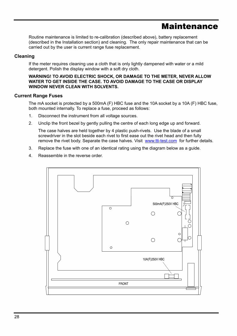
Current Range Fuses The mA socket is protected by a 500mA (F) HBC fuse and the 10A socket by a 10A (F) HBC fuse, both mounted internally. To replace a fuse, proceed as follows:
1. Disconnect the instrument from all voltage sources.
2. Unclip the front bezel by gently pulling the centre of each long edge up and forward.
The case halves are held together by 4 plastic push-rivets. Use the blade of a small screwdriver in the slot beside each rivet to first ease out the rivet head and then fully remove the rivet body. Separate the case halves. Visit www.tti-test.com for further details.
3. Replace the fuse with one of an identical rating using the diagram below as a guide.
4. Reassemble in the reverse order.
28
Remote Operation
Introduction RS232 remote control is standard and can be used either in a conventional one-to-one mode or in addressable mode as part of an ARC (Addressable RS232 Chain) system; RS232 can only be used when the meter is powered from an AC supply.
GPIB (IEEE-488) remote control is available in addition to RS232 on a mains-only version; it is not a retrofittable option.
The ARC (Addressable RS232 Chain) interface allows a collection of instruments, up to a maximum of 32, to be connected to a single serial interface on a PC or other computer system. Each instrument may then be uniquely addressed so that commands for that instrument may be sent and ignored by all other instruments connected to the interface. Additionally, ARC instruments may be used on a simple RS232 interface in non-addressable mode without modification.
Available as an option is the ARCTALK software package for IBM compatible PCs. At the simplest level, ARCTALK provides realtime direct control of instruments on the ARC bus from the PC’s keyboard. However, it can be used more effectively to create complete ‘programs’ within which several instruments can be set-up and/or measurements read back; responses can be captured in a ‘response’ file for later use, e.g. by another application which could, for example, generate a graph of the data.
The following sections detail the operation of the instrument via both GPIB and ARC (RS232). Where operation is common no distinction is made between the two; where differences occur these are details in separate sections for GPIB and ARC.
RS232/GPIB Selection The required interface must be selected using the rear panel slide switch before the meter is switched on. Set the switch and switch on; if GPIB is selected the main display will show IEEE for 1 second as verification.
Address and Baud Rate Selection Each instrument connected to the ARC or GPIB bus must be assigned a unique address and, in the case of ARC, all must be set to the same baud rate.
To set the address press Shift then Addr (the shifted function of FUNCTION); the main display shows Add and the secondary display shows the current address setting. Increment/decrement the address with the Range Up/Range Down beep or enter the default address (1) by pressing Clr (the edit function of Cancel). Exit address selection mode by pressing Esc.
To set the Baud rate press Shift then Baud (the shifted function of Run); the main display shows bAUd and the secondary display shows the current Baud setting. Step through all possible settings using the Range Up/Range Down keys or enter the default rate (9600) by pressing Clr (the edit function of Cancel). Exit Baud selection mode by pressing Esc.
Two further settings, PC-02 and Trig, are listed with the Baud rate. These are for when the RS232 interface is used with a parallel printer or remote data-logger trigger, respectively; refer to the Printing and Data Logger sections for details.
Remote/Local Operation At power-on the instrument will be in the local state; in this state all keyboard operations are possible. When the instrument is addressed to listen and a command is received the remote state will be entered and the REM symbol will show in the display. In this state the keyboard is
29
locked out and only remote commands will be processed. The instrument may be returned to the local state by pressing the Local key; however, the effect of this action will remain only until the instrument is addressed again or receives another character from the ARC interface, when the remote state will once again be entered.
ARC Interface
ARC Interface Connections The 9-way D-type serial interface connector is located on the instrument rear panel. The pin connections are as shown below:
Pin Name Description
1 - Power to optional PC-02 2 TXD Transmitted data from instrument 3 RXD Received data to instrument 4 - No internal connection 5 GND Signal ground 6 - No internal connection 7 RXD2 Secondary received data (see diagram) 8 TXD2 Secondary transmitted data (see diagram) 9 GND Signal ground
Pins 2, 3 and 5 may be used as a conventional RS232 interface with XON/XOFF handshaking. Pins 7, 8 and 9 are additionally used when the instrument is connected to the ARC interface.
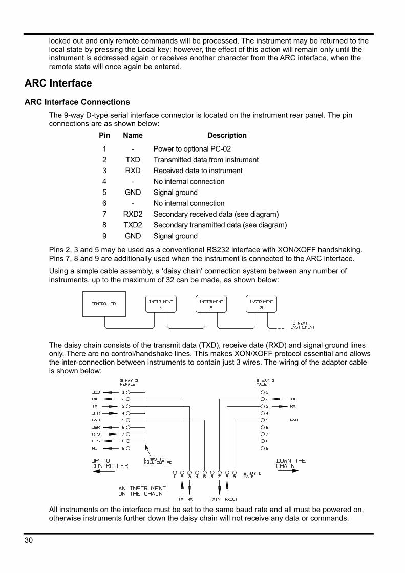
Using a simple cable assembly, a ‘daisy chain' connection system between any number of instruments, up to the maximum of 32 can be made, as shown below:
The daisy chain consists of the transmit data (TXD), receive date (RXD) and signal ground lines only. There are no control/handshake lines. This makes XON/XOFF protocol essential and allows the inter-connection between instruments to contain just 3 wires. The wiring of the adaptor cable is shown below:
All instruments on the interface must be set to the same baud rate and all must be powered on, otherwise instruments further down the daisy chain will not receive any data or commands.
30
The ARC standard for the other interface parameters is as follows: Start bits 1 Data bits 8 Parity None Stop bits 1 In this instrument, as with most other ARC instruments, these parameters are fixed.
ARC Character Set Because of the need for XON/XOFF handshake it is possible to send ASCII coded data only; binary blocks are not allowed. Bit 7 of ASCII codes is ignored, i.e. assumed to be low. No distinction is made between upper and lower case characters in command mnemonics and they may be freely mixed. The ASCII codes below 20H (space) are reserved for interface control.
ARC Interface Control Codes All instruments intended for use on the ARC bus use the following set of interface control codes. Codes between 00H and 1FH which are not listed here as having a particular meaning are reserved for future use and will be ignored. Mixing interface control codes inside instrument commands is not allowed except as stated below for CR and LF codes and XON and XOFF codes.
When an instrument is first powered on it will automatically enter the Non- Addressable mode. In this mode the instrument is not addressable and will not respond to any address commands. This allows the instrument to function as a normal RS232 controllable device. This mode may be locked by sending the Lock Non-Addressable mode control code 04H (LNA). The controller and instrument can now freely use all 8-bit codes and binary blocks but all interface control codes are ignored. To return to addressable mode the instrument must be powered off.
To enable addressable mode after an instrument has been powered on the Set Addressable Mode control code, 02H (SAM), must be sent. This will then enable all instruments connected to the ARC bus to respond to all interface control codes. To return to Non-Addressable mode the Lock Non-Addressable mode control code must be sent which will disable addressable mode until the instruments are powered off.
Before an instrument is sent a command it must be addressed to listen by sending the Listen Address control code, 12H (LAD), followed by a single character which has the lower 5 bits corresponding to the unique address of the required instrument, e.g. the codes A-Z or a-z give the addresses 1-26 inclusive while @ is address 0 and so on. Once addressed to listen the instrument will read and act upon any commands sent until the listen mode is cancelled.
Because of the asynchronous nature of the interface it is necessary for the controller to be informed that an instrument has accepted the listen address sequence and is ready to receive commands. The controller will therefore wait for code 06H (ACK) before sending any commands, The addressed instrument will provide this ACK. The controller should time-out and try again if no ACK is received within 5 seconds.
Listen mode will be cancelled by any of the following interface control codes being received: 12H LAD Listen Address followed by an address not belonging to this instrument.
14H TAD Talk Address for any instrument.
03H UNA Universal Unaddress control code.
04H LNA Lock Non-Addressable mode control code.
18H UDC Universal Device Clear.
Before a response can be read from an instrument it must be addressed to talk by sending the Talk Address control code, 14H (TAD) followed by a single character which has the lower 5 bits corresponding to the unique address of the required instrument, as for the listen address control
31
code above. Once addressed to talk the instrument will send the response message it has available, if any, and then exit the talk addressed state. Only one response message will be sent each time the instrument is addressed to talk. Talk mode will be cancelled by any of the following interface control codes being received:
12H LAD Listen Address for any instrument.
14H TAD Talk Address followed by an address not belonging to this instrument.
03H UNA Universal Unaddress control code.
04H LNA Lock Non-Addressable mode control code.
18H UDC Universal Device Clear.
Talk mode will also be cancelled when the instrument has completed sending a response message or has nothing to say.
The interface code 0AH (LF) is the Universal Command and response Terminator (UCT); it must be the last code sent in all commands and will be the last code sent in all responses.
The interface code 0DH (CR) may be used as required to aid the formatting of commands; it will be ignored by all instruments. Most instruments will terminate responses with CR followed by LF.
The interface code 13H (XOFF) may be sent at any time by a listener (instrument or controller) to suspend the output of a talker. The listener must send 11H (XON) before the talker will resume sending. This is the only form of handshake control supported by ARC.
ARC Interface Control Code List 02H SAM Set Addressable mode.
03H UNA Universal Unaddress control code.
04H LNA Lock Non-Addressable mode control code.
06H ACK Acknowledge that listen address received.
0AH UCT Universal Command and response Terminator.
0DH CR Formatting code, otherwise ignored.
11H XON Restart transmission.
12H LAD Listen Address - must be followed by an address belonging to the required instrument.
13H XOFF Stop transmission.
14H TAD Talk Address - must be followed by an address belonging to the required instrument.
18H UDC Universal Device Clear.
GPIB Interface The GPIB interface pin connections are as specified in IEEE Std 488.1 - 1987. The instrument contains the following IEEE 488.1 subsets:
Parallel Poll PP0
Device Clear DC1
Device Trigger DT0
Controller C0
Electrical Interface E2
Source Handshake SH1
Acceptor Handshake AH1
Talker T8
Listener L4
Service Request SR0
Remote Local RL2
This instrument does not support parallel polling or IEEE-488.2 error handling.
32
ARC Remote Command Formats Commands are sent as <PROGRAM MESSAGES> by the controller. A <PROGRAM MESSAGE> consists of zero or more <PROGRAM MESSAGE UNITS> each separated by a <PROGRAM MESSAGE UNIT SEPARATOR> which is the semi-colon character ‘;’ (3BH).
A <PROGRAM MESSAGE UNIT> is any of the commands in the REMOTE COMMANDS section.
<PROGRAM MESSAGES> are separated by a <PROGRAM MESSAGE TERMINATOR> which is the new line character (0AH).
Responses from the instrument to the controller are sent as <RESPONSE MESSAGES>. A <RESPONSE MESSAGE> consists of one <RESPONSE MESSAGE UNIT> followed by a <RESPONSE MESSAGE TERMINATOR>, which is the carriage return character followed by the new line character (0DH 0AH).
Each query produces a specific <RESPONSE MESSAGE> which is listed along with the command in the REMOTE COMMANDS section.
<WHITE SPACE> is ignored except in command identifiers. e.g. `∗C LS' is not equivalent to `∗CLS'. <WHITE SPACE> is defined as character codes 00H to 20H inclusive with the exception of the codes specified as ARC interface commands.
The high bit of all characters is ignored. The commands are case insensitive. The commands are case insensitive.
GPIB Remote Command Formats Commands are sent as <PROGRAM MESSAGES> by the controller. Each message consists of zero or more <PROGRAM MESSAGE UNIT> elements separated by <PROGRAM MESSAGE UNIT SEPARATOR> elements. <PROGRAM MESSAGES> are separated by <PROGRAM MESSAGE TERMINATOR> elements.
A <PROGRAM MESSAGE TERMINATOR> is the new line character, NL, (0AH) A <PROGRAM MESSAGE UNIT SEPARATOR> is the semi-colon character ';' (3BH). A <PROGRAM MESSAGE UNIT> is any of the commands in the REMOTE COMMANDS section.
Responses from the instrument to the controller are sent as <RESPONSE MESSAGES>. A <RESPONSE MESSAGE> consists of one <RESPONSE MESSAGE UNIT> followed by a <RESPONSE MESSAGE TERMINATOR>.
A <RESPONSE MESSAGE TERMINATOR> is the new line character with the END message NL^END.
Each query produces a specific <RESPONSE MESSAGE> which is listed along with the command in the REMOTE COMMANDS section.
<WHITE SPACE> is ignored except in command identifiers. e.g. `*C LS' is not equivalent to `*CLS'. <WHITE SPACE> is defined as character codes 00H to 20H inclusive with the exception of the NL character (0AH).
The high bit of all characters is ignored.
The commands are case insensitive.
33
Remote Commands This section details all the commands available. Note that each command is completely executed before the next command is started. When a command generates a response that response will be sent immediately if in non-addressable mode or when addressed to talk if in addressable mode. Sending any valid command clears XOFF.
The following nomenclature is used:
<string> Any valid string listed for the command (the <> are not required).
[...] Any item(s) enclosed in these brackets are optional parameters.
<rmt> <RESPONSE MESSAGE TERMINATOR>, i.e. Carriage Return character followed by New Line character (0DH 0AH).
<nrf> A number in any format. e.g. 12, 12.00, 1.2 e1 and 120 e- 1 are all accepted as the number 12. Any number when received, is converted to the required precision consistent with its use then rounded up to obtain the value for the command. If the number is too large for the selected function then the value is set to 99999 on the highest range for that function.
General Commands
∗ IDN? Returns the instrument identification in the form:
<NAME>, <MODEL>, 0, <VERSION>
where <NAME> is the manufacturer’s name, <MODEL> defines the instrument type and <VERSION> is the revision level of the installed software.
READ? Returns the next reading from the main display immediately after the command has been parsed.
The syntax of the response is:
<ASCII data><rmt>
where <ASCII data> is a 18 character string divided into 10-character plus 8-character fields. The first field is the measurement value and consists of the following:
Digit
1 space (for positive values) or a minus sign.
2 .... 7 a 5 digit number plus decimal point in the format of the range selected for the measurement.
8 .... 10 the exponent in the form e00, e-3, e03, etc., i.e. engineering units.
An overload reading (i.e. >12000 counts) is returned as ‘OVLOAD’ in place of the 5 digits plus point; a calculation overflow (relevant to some function results) is returned as ‘OVFLOW’. In both cases a minus sign can also be shown to indicate negative overload and overflow respectively.
The second field is the unit indication and will be one of the following; the field starts with a space and additional spaces are sent at the end of the field to always make it 8 characters long:
34
V DC V AC V AC+DC
A DC A AC A AC+DC
Hz Ohms F
V (for diode test) dB
W VA %
Examples:
101.23e-3 V DC (101.23mV) -10.001e00 V DC (-10.001V) 00.123e00 V AC+DC (0.123V) 100.01e03 Hz (100.01kHz) 01.010e-6 F (1.01µF)
READ2? Returns the next reading from the secondary display immediately after the command has been parsed. The syntax is as for READ? described above. If the secondary display is currently showing the range of the main display the response will be RANGE.
EVERY Sends every reading from the main display until stopped by STOP or any other command. The syntax of each reading is:
<ASCII data><rmt>
where <ASCII data> is an 18-character string divided into two fields (value followed by units) exactly as for the standard READ? response, see that command section for details.
STOP Cancels the EVERY command.
∗RST Resets the meter to the factory default settings except for the Address and Baud rate of the RS232 interface itself.
Main Display Commands
VDC [<string>] Sets the main display to dc Volts and optionally sets the range; if no range is specified the display defaults to autorange. The following <strings> can be used to set the range:
<100MV>, <1000MV>, <10V>, <100V>, <1000V>
VAC [<string>] Sets the main display to ac Volts and optionally sets the range; if no range is specified the display defaults to autorange. The following <strings> can be used to set the range:
<100MV>, <1000MV>, <10V>, <100V>, <750V>
35

VACDC [<string>] Sets the main display to ac+dc Volts and optionally sets the range; if no range is specified the display defaults to autorange.
The following <strings> can be used to set the range:
<100MV>, <1000MV>, <10V>, <100V>, <750V>
IDC [<string>] Sets the main display to dc Amps and optionally sets the range; if no range is specified the display defaults to mA autorange.
The following <strings> can be used to set the range:
<1MA>, <100MA>, <10A>
IAC [<string>] Sets the main display to ac Amps and optionally sets the range; if no range is specified the display defaults to mA autorange.
The following <strings> can be used to set the range:
<1MA>, <100MA>, <10A>
IACDC [<string>] Sets the main display to ac+dc Amps and optionally sets the range; if no range is specified the display defaults to autorange.
The following <strings> can be used to set the range:
<1MA>, <100MA>, <10A>.
OHMS [<string>] Sets the main display to Ohms and optionally sets the range; if no range is specified the display defaults to autorange.
The following <strings> can be used to set the range:
<100>, <1000>, <10K>, <100K>, <1000K>, <10M>, <20M>
CONT Sets the main display to continuity test.
DIODE Sets the main display to diode test.
CAP [<string>] Sets the main display to Capacitance and optionally sets the range; if no range is specified the display defaults to autorange.
The following <strings> can be used to set the range:
<10NF>, <100NF>, <1UF>, <10UF>, <100UF>
FREQ [<string>] Sets the main display to Frequency and optionally sets the range; if no range is specified the display defaults to autorange. The following <strings> can be used to set the range:
<100HZ>, <1000HZ>, <10KHZ>, <100KHZ>
36
AUTO Sets the main display to autorange, except for Continuity or Diode check.
MAN Sets the main display to manual, i.e. the current range is ‘locked’.
Dual Measurement Mode Commands
VDC2 Sets the secondary display to dc Volts (autoranging).
VAC2 Sets the secondary display to ac Volts (autoranging).
IDC2 [<string>] Sets the secondary display to dc Amps and optionally selects mA (autoranging) or the 10A range; if no range is specified the existing setting is used.
The following <strings> can be used:
<1MA>,<100MA>, <10A>
If the main display is set to ac Amps the secondary range will be the same as the main display range.
IAC2 [<string>] Sets the secondary display to dc Amps and optionally selects the 10A range; if no range is specified the display defaults to mA autorange.
The following strings can be used:
<1MA>, <100MA>, <10A>
If the main display is set to dc Amps the secondary range will be the same as the main display range.
FREQ2 Sets the secondary display to frequency (autoranging). Vac or Iac must first have been selected in the main display.
First Level Modifier Commands
NULL Nulls the main display and sets it to manual, i.e. the current range is held. the un-nulled reading will be shown in the secondary display if the meter is not in dual measurement mode, except for capacitance.
NULLOFF Cancels Null operation.
HOLD Holds the value in the main display. The normal, updated, reading will be shown in the secondary display if the meter is not in dual measurement mode, except for capacitance.
37
HOLD OFF Cancels Hold mode.
DB [<string>] Sets the main display to show the dB value of the Vac measurement (which must have first been selected in the main display) and optionally sets the reference impedance; if no impedance is specified the existing value is used.
The following <strings> can be used to set the impedance.
<50>, <75>, <93>, <110>, <124>, <125>, <135>, <150>, >250>, <300>, <500>, <600>, <800>, <900>, <1000>, <1200>, <8000>.
DBOFF Cancels DB mode.
Second Level Modifier Commands
DELTA [<nrf>] Selects the Delta % function and optionally sets the reference value; if no reference is specified the existing value is used. The percentage deviation shows in the secondary display.
DELTA? Returns the Delta % value. The syntax of the response is:
<ASCII data><rmt>
where <ASCII data> is an 18-character string divided into two fields (value followed by %) exactly as for the standard READ? response; see that command section for details.
If Delta% is greater than 999.99% the response value will be <OVFLOW>; if the Delta% function is not running the response value will be zero.
LIMITS [<nrf>, <nrf>] Selects the Limits function and optionally sets the limits (LO, HI); if no reference is specified the existing value is used. PASS, LO or HI is shown in the secondary display.
LIMITS? Returns the result of the latest Limits comparison. The syntax of the response is:
<ASCII data><rmt>
where <ASCII data> is either PASS, LOW, HIGH, or OFF.
PASS indicates that the reading was between or equal to one (or both) of the limits.
LOW indicates that the reading was less than the LO set limit.
HIGH indicates that the reading was above the HI set limit.
OFF indicates that the Limits function was not running.
MMON Starts the Min-Max recording mode, initially setting both Min and Max to the same value. If Min-Max mode is already running, Min and Max are reset to the same value and recording starts again.
38
MM? Returns the recorded Min and Max values. The syntax of the response is:
<ASCII data for Min><ASCII data for Max><rmt>
where each <ASCII data> is an 18-character string divided into two fields (value followed by units) exactly as for the standard READ? response; see that command section for details. The two 18-character strings are separated by 2 spaces.
AXB [<nrf>, <nrf>] Starts the Ax+b scaling function and optionally sets the A and b parameters; if A and b are not sent the existing values are used.
AXB? Returns the result of the Ax+b scaling function. The syntax of the response is:
<ASCII data><rmt>
where <ASCII data> is a 10-character string in the same format as the first (value) field of the standard READ? response, see that command for details. If Ax + b is not running a zero value will be returned.
WATTS [<nrf>] Selects the Watts function and optionally sets the reference impedance; if no impedance is specified the existing value is used. Vac or Vdc must first have been specified in the main display; Watts shows in the secondary display.
WATTS? Returns the result of the Watts calculation. The syntax of the response is:
<ASCII data><rmt>
where <ASCII data> is an 18-character string divided into two fields (value followed by units) exactly as for the standard READ? response, see that command section for details. If the Watts function is not running a zero value will be returned.
VA Sets the VA function; Vac or Vdc must first have been selected in the main display and the meter must be connected for both voltage and current measurement. VA shows in the secondary display.
VA? Returns the result of the VA calculation. The syntax of the response is:
<ASCII data><rmt>
where <ASCII data> is an 18-character string divided into two fields (value followed by units) exactly as for the standard READ? response, see that command section for details. If the VA function is not running a zero value will be returned.
CANCEL Cancels the second level modifier currently running.
39
Data Logging Commands
LOGON [<nrf>] Sets Data Logger running and optionally sets the internal logger interval timer; when no interval is specified the existing value is used.
Setting the interval to 0000 disables the timer but still allows the logger to be triggered manually (from the keyboard) or by remote command (TRIG), see below; triggering by remote contact closure is not possible during remote control operation.
LOG? Returns the contents of all valid locations in the data logger store, starting at location 001.
The syntax of the response is:
<ASCII data><rmt>
where <ASCII data> consists of up to 100 complete results, separated by commas, each result comprising three fields. The first field is the reading number, consisting of 3 digits followed by three spaces. The following two fields each of 8 digits, contain the measurement value and measurement units respectively, in exactly the same format as the response to the standard READ? command, see that command section for details.
TRIG With the data logger on, a reading will be stored each time the TRIG command is set. Since the remote command is OR’ed with the internal timer, either both can be run together or the internal timer can be disabled by setting the interval to 0000 seconds.
CANCEL Stops the logger running.
LOGCLEAR Cancels the logger function, if it is running, and clears the results from the logger memory.
Calibration Commands
SETCAL Used for calibration only - refer to Service Manual.
STEPCAL Used for calibration only - refer to Service Manual.
REJ50 Optimizes analogue-to-digital converter for 50Hz rejection; see Calibration section of manual for further explanation.
REJ60 Optimizes analogue-to-digital converter for 60Hz rejection; see Calibration section of manual for further explanation.
40
Default Settings
The meter is put into the following default condition as a result of a system reset (hold Cancel down at switch on) or by the ∗RST remote command.
Function set to DC Volts, single measurement mode.
Autoranging mode set.
All first level modifiers cancelled, including Ohms Null.
All second level modifiers cancelled.
Ax + b factors set to A = 1.0000 and b = 00000
Limits set to 0.0000
Delta % reference set to 10000
dB reference impedance set to 600Ω
Watts reference impedance set to 50Ω
Set data logger off and timer to 0000 seconds but preserve logger store contents.
Bus address set to 1 (not by ∗RST)
Baud rate set to 9600 (not by ∗RST)
Calibration constants and the 50/60Hz rejection setting are unaffected by a system reset.
TEST EQUIPMENT RISK ASSESSMENT
Recommendation from the U.K. Health and Safety Executive
Users of this equipment and or their employers are reminded that Health and Safety Legislation require them to carry out valid risk assessments of all electrical work so as to identify potential sources of electrical danger and risk of electrical injury such as from inadvertent short circuits. Where the assessments show that the risk is significant then the use of fused test leads constructed in accordance with the HSE guidance note GS38 ‘Electrical Test Equipment’ for use by electricians’ should be used.
41

Thurlby Thandar Instruments Ltd Glebe Road, Huntingdon, Cambridgeshire PE29 7DR, England
Telephone: +44 (0)1480 412451 Fax: +44 (0)1480 450409 e mail: [email protected]
International website: www.tti-test.com UK website: www.tti.co.uk
Book Part No. 48581-1160 Issue 7