Embed Size (px)
Citation preview
170 Montauk170 Montauk
170 Montauk
“The mission of Boston Whaler®
is to provide consumers with thesafest, highest quality, most durable
boats in the world”

iii170 MontaukR
1958, The legend is bornas company founder Dick Fisherdemonstrates a Boston Whaler’s
total unsinkability.
RT H E U N S I N K A B L E L E G E N DTM
Welcome to the Boston Whaler family! Congratulations on your purchase of a Boston Whaler boat.
For over 50 years now, Boston Whaler has been represented by a select group of the best dealers in the boating industry. Boston Whaler depends on this extremely qualifi ed network of dealers to provide you, our customer, with a truly exceptional boating experience.
Should you have any questions or concerns regarding your boat, please don’t hesitate to contact your selling dealer. They will be more than happy to provide you with all the information andassistance that you require.
Information and assistance is also available at our corporate website, www.whaler.com. At whaler.com you will fi nd information about upcoming events happening in your area. Things like fi shing tournaments, rendezvous, boat shows, and many others are listed, as are maintenance tips and back issues of our e-newsletter, the Whaler News.
Since Boston Whaler’s inception in 1958, we have been committed to providing customers with the safest, highest quality, most durable boats in the world. I am confi dent that you, as a Whaler owner, will also appreciate the quality and pride that is built into every Boston Whaler boat.
From all of us here at Whaler, thank you for purchasing one of our boats. May it bring you many years of boating enjoyment.
iv 170 MontaukR
PLEASE KEEP THIS OWNER’S MANUAL PACKET IN A SECURE PLACE, AND BE SURETO HAND IT OVER TO THE NEW OWNER IF YOU SELL THE BOAT.
Boston Whalers are built to last. For over 50 years Boston Whaler® has strived to make each model better, providing you with a safe and fun boating experience. That is the reason we offer a 10 year limited transferable warranty. It is also an excellent reason why you can trust the safety of your family and friends to a Boston Whaler®.
R i c h a r d T. F i s h e r w a s p o s t h u m o u s l y inducted into the National Marine Manufacturer’s Association (NMMA) Hall of Fame on September 26, 1996 for accomplishments made in marine engineering and construction.
HISTORY
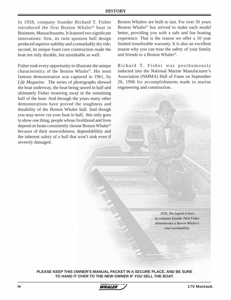
1958, The legend is bornas company founder Dick Fisher demonstrates a Boston Whaler’s
total unsinkability.
In 1958, company founder Richard T. Fisher introduced the first Boston Whaler® boat in Braintree, Massachussetts. It featured two signifi cant innovations: first, its twin sponson hull design produced superior stability and a remarkably dry ride; second, its unique foam core construction made the boat not only durable, but unsinkable as well.
Fisher took every opportunity to illustrate the unique characteristics of the Boston Whaler®. His most famous demonstration was captured in 1961, by Life Magazine. The series of photographs showed the boat underway, the boat being sawed in half and ultimately Fisher motoring away in the remaining half of the boat. And through the years many other demonstrations have proved the toughness and durability of the Boston Whaler hull. And though you may never cut your boat in half, this only goes to show one thing, people whose livelihood and lives depend on boats consistently choose Boston Whaler® because of their seaworthiness, dependablility and the inherent safety of a hull that won’t sink even if severely damaged.
v170 MontaukR
Welcome Letter ..........................................iiiHistory ......................................................ivPreface .....................................................viiBoston Whaler Limited Warranty ............... viiiPrivacy Statement ...................................... xIntroduction ...............................................xi Owner’s manual .....................................xi Your responsibilites .................................xi Source of Information .............................xi Warranties .............................................xi Contact Phone Numbers and Internet Addresses...............................xi
Section 1 • Safety
Explanation of Safety Labels .................... 1-1Warning Labels ....................................... 1-1Safe Boating means ................................. 1-2 In Addition ....................................... 1-2Safe Boating Checklist ............................. 1-2 Before departure ................................. 1-2 Trailering (if applicable) ........................ 1-2 After Return ........................................ 1-2General Considerations ............................ 1-3Maintain Control ...................................... 1-3Boarding ................................................. 1-3Impaired Operation ................................. 1-3Legally Mandated Equipment (Minimum Required) ............................ 1-5 Personal Flotation devices (PFD’s) ......... 1-5 Fire Extinquisher (Portable) .................. 1-5 Whistle, Horn ...................................... 1-5 Visual Distress Signal ........................... 1-5Additional recommended Equipment for Safe Operation .................................... 1-5Carbon Monoxide (CO) ............................ 1-6 In The Event CO Alarm Activates .......... 1-6Lifesaving Equipment............................... 1-7 PFD Requirement ................................ 1-7 PFD Classifi cation ................................ 1-7Emergency Situations .............................. 1-9 Medical Emergency .............................. 1-9 Water Rescue ...................................... 1-9 Returning to the victim ...................... 1-9 Making contact ................................. 1-9
TABLE of CONTENTS
Getting back on board ....................... 1-9Fire ....................................................... 1-9 To lessen the danger of fi re ................ 1-10Flooding, Swamping and Capsizing ......... 1-10 Flooding ........................................... 1-10 Swamping ......................................... 1-10 Capsizing .......................................... 1-10Collision ................................................ 1-11Propulsion, Control or Steering Failure .... 1-11Grounding ............................................ 1-11Distress Signals ..................................... 1-11 Visual distress signals (VDS) ............... 1-11 Audible distress signals ...................... 1-12Radio Communication ............................ 1-12Weather ............................................... 1-12Swimming, Diving & Water Skiing ........... 1-13 Swimming ......................................... 1-13 Diving ............................................... 1-13 Water Skiing ..................................... 1-14 Water Skiing Signals .......................... 1-14Emergency Engine Stop Switch .............. 1-16Float Plan ............................................. 1-16Chart Your Course ................................. 1-16Environmental Considerations ................ 1-17 Fuel & Oil Spillage ............................. 1-17 Excessive Noise ................................. 1-17 Wake/Wash ....................................... 1-17Homeland Security Restrictions .............. 1-18America’s Waterway Watch .................... 1-18Warning Label Locations ........................ 1-18Key To Symbols Used on Controls & Prints ............................................ 1-20
Section 2 • General Information
Construction Standards ............................ 2-1Our Hull .................................................. 2-1 Hull Identifi cation Number .................... 2-1Servicing Your Boston Whaler ................... 2-1Manufacturer’s Certifi cation ...................... 2-1 CE Certifi cation design Category ........... 2-3 Power Capacity .................................... 2-3Specifi cations & Dimensions ..................... 2-4Passenger Locations ................................ 2-5Location Of Thru-Hull Fittings ................... 2-6Features ................................................. 2-7
vi 170 MontaukR
Optional Features .................................... 2-8Seating ................................................... 2-9Recommended Seating .......................... 2-10Control Station Switch Panel................... 2-11Gear Shift & Throttle Control .................. 2-12Power Trim & Tilt .................................. 2-12Navigation Lighting ................................ 2-13 Operating The navigation Lighting ...... 2-13Steering ............................................... 2-14Steering Pull ......................................... 2-14 BaystarTM Hydraulic Steering (Option) . 2-14Trolling Motor Panel (Option) ................. 2-15Canvas (Option) .................................... 2-16Propeller ............................................... 2-17Docking, Lifting and Trailering ................ 2-18 Docking ............................................ 2-18 Lifting ................................................... 2-18 Trailering .......................................... 2-19Trailer safety ......................................... 2-19 Securing the Boat to the Trailer .......... 2-19 Securing the Trailer to the Tow Vehicle .................................... 2-19 Disc Brakes (Option) .............................. 2-20 Operation, Care & Maintenance .......... 2-20Trailer Description ................................. 2-21
Section 3 • Systems & Components Overview & Operation
Bilge Pump ............................................. 3-1 Maintenance ....................................... 3-1 Fuel & Oil Spillage ............................... 3-1Fuel System ............................................ 3-2 Static Electricity and the Fuel System . 3-3 Ethanol-Blended Fuels ....................... 3-3Starting the Engine.................................. 3-5 Prior to Starting ................................... 3-5Warming Up the Engine ........................... 3-6Stopping the Engine ................................ 3-6Livewell (Option) ..................................... 3-7Operating Your MP3 Player (Option) ......... 3-8Operating Your MP3 Player Usingthe USB Input (Option) ............................ 3-8Anchoring ............................................... 3-9
Considerations ........................................ 3-9 Lowering the Anchor ............................... 3-9 Setting the Anchor ............................... 3-9 Weighing the Anchor ........................... 3-9Anchor Light ........................................... 3-9 To Install the Anchor Light ................... 3-9
Section 4 • Electrical
Electrical System ..................................... 4-1DC Electrical System ................................ 4-1Battery ................................................... 4-1 Battery Box ......................................... 4-1Main DC Breaker ..................................... 4-2Component Breakers ............................... 4-212V Accessory Receptacle ........................ 4-2Battery Switch (CE Option) ...................... 4-3Trolling Motor Wiring ............................... 4-3Wiring Identifi cation Chart ....................... 4-4Electrical Schematics & Harnesses ............ 4-5
Section 5 • care & Maintenance
Routine Care & Maintenance .................... 5-1 Hull .................................................... 5-1Waxing the Gel Coat Surfaces .................. 5-1Hull Maintenance..................................... 5-2Hull Blistering ......................................... 5-2 Prevention .......................................... 5-1Bottom Painting ...................................... 5-2 Bottom Painting a Bare Hull .................. 5-3 Bottom Painting a Pre-Painted Hull ........ 5-3Rubrail care ............................................ 5-4Cleaning Fiberglass & Non-Skid ................ 5-4Stainless Steel Care ................................. 5-4Aluminum Care ....................................... 5-5Cushions................................................. 5-5 To Clean Your Cushions ........................ 5-5Cleaning Your Instrument Gauges ............ 5-6 Canvas Care and Maintenance .................. 5-6 Maintaining a Good Appearance ............ 5-6 On a Regular Basis ............................ 5-6
vii170 MontaukR
This Owner’s Manual has been written to provide specifi c information about your boat and it should be read carefully. Keep this booklet with the Manuals in the Owner’s Manual Packet. The Owner’s Manual Packet has been compiled to help you operate your boat with safety and pleasure. It contains details of the boat, the equipment supplied or fi tted, it’s systems and information on it’s operation and maintenance. Please familiarize yourself with the boat and it’s operation before using it. If this is your fi rst boat, or you are changing to a type of boat you are not familiar with, for your own comfort and safety, please ensure that you obtain handling and operating experience before “assuming command” of your boat. Your Boston Whaler® dealer or local Yacht Club will be pleased to advise you of marine safety classes and safe boating classes in your area.
PREFACE
INFORMATION IN THIS PUBLICATION IS BASED ON THE LATEST PRODUCT SPECIFICATIONS AVAILABLE AT PRINTING, BOSTON WHALER® BOATS, INC. RESERVES THE RIGHT TO MAKE CHANGES AT ANY TIME WITHOUT NOTICE, IN THE COLORS, EQUIPMENT, SPECIFICATIONS, MATERIALS AND PRICES OF ALL MODELS, OR TO DISCONTINUE MODELS. SHOULD CHANGES OR MODIFICATIONS TO THE MODELS BE MADE BOSTON WHALER® IS NOT OBLIGATED TO MAKE SIMILAR CHANGES OR MODIFICATIONS TO MODELS SOLD PRIOR TO THE DATE OF SUCH CHANGES.
BOSTON WHALER® • A BRUNSWICK COMPANYMRP #1968580
Printed in the U.S.A. © Boston Whaler, Inc. All rights reserved.
170 MontaukJune, 2009
THE FOLLOWING ARE REGISTERED TRADEMARKS OF THE BRUNSWICK CORPORATION:
MONTAUK, BOSTON WHALER®.
R
Specifi cations and standard equipment are subject to change. Boston Whaler is not responsible for changes to parts or accessories manufactured by companies other than Boston Whaler. Active Deck Suspension System, Boston Whaler, Whaler, the Boston Whaler logo, Conquest, Dauntless, Montauk, and Outrage are registered trademarks of Boston Whaler, Incorporated. Accutrack, Unibond, The Unsinkable Legend, Ventura, and Whaleboard are trademarks of Boston Whaler, Incorporated. Mercury and Optimax are registered trademarks of Mercury Marine, and SmartCraft and Verado are trademarks of Mercury Marine. Trademarks of others are the property of their respective owners. All mercury engine information provided by Mercury Marine, June 2007. Information contained within this publication is believed to be correct at the time of printing.
Cleaning stubborn Stains ...................... 5-7 Maintaining Zippers and Hardware ............ 5-7Cleaning Acrylic Windscreen ..................... 5-7Long term Storage .................................. 5-7 Engine ................................................ 5-7 Fuel System ........................................ 5-8 Electrical System ................................. 5-8 Battery ............................................... 5-8 Deck ................................................... 5-8 Drainage ............................................. 5-8 Avoid Loss .......................................... 5-9 Cover.................................................. 5-9
Trailer Storage ........................................ 5-9 Environment ........................................... 5-9Reinforcement Location Diagram ............ 5-10Reinforcement Locations ........................ 5-11Maintenance Log ................................... 5-12
Attachments Commissioning Checklist Product Registration Card
viii 170 MontaukR
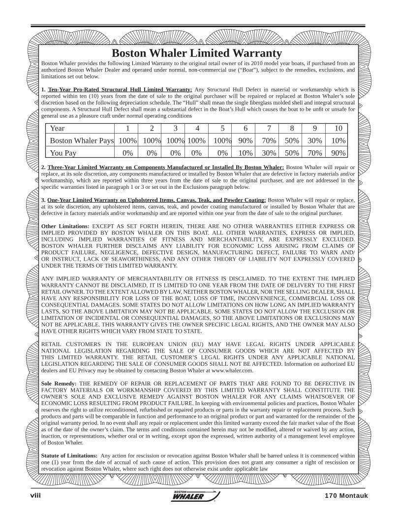
Boston Whaler provides the following Limited Warranty to the original retail owner of its 2010 model year boats, if purchased from an authorized Boston Whaler Dealer and operated under normal, non-commercial use (“Boat”), subject to the remedies, exclusions, and limitations set out below.
1. Ten-Year Pro-Rated Structural Hull Limited Warranty: Any Structural Hull Defect in material or workmanship which is reported within ten (10) years from the date of sale to the original purchaser will be repaired or replaced at Boston Whaler’s sole discretion based on the following depreciation schedule. The “Hull” shall mean the single fi berglass molded shell and integral structural components. A Structural Hull Defect shall mean a substantial defect in the Boat’s Hull which causes the boat to be unfi t or unsafe for general use as a pleasure craft under normal operating conditions
2. Three-Year Limited Warranty on Components Manufactured or Installed By Boston Whaler: Boston Whaler will repair or replace, at its sole discretion, any components manufactured or installed by Boston Whaler that are defective in factory materials and/or workmanship, which are reported within three years from the date of sale to the original purchaser, and are not addressed in the specifi c warranties listed in paragraph 1 or 3 or set out in the Exclusions paragraph below.
3. One-Year Limited Warranty on Upholstered Items, Canvas, Teak, and Powder Coating: Boston Whaler will repair or replace, at its sole discretion, any upholstered items, canvas, teak, and powder coating manufactured or installed by Boston Whaler that are defective in factory materials and/or workmanship and are reported within one year from the date of sale to the original purchaser. Other Limitations: EXCEPT AS SET FORTH HEREIN, THERE ARE NO OTHER WARRANTIES EITHER EXPRESS OR IMPLIED PROVIDED BY BOSTON WHALER ON THIS BOAT. ALL OTHER WARRANTIES, EXPRESS OR IMPLIED, INCLUDING IMPLIED WARRANTIES OF FITNESS AND MERCHANTABILITY, ARE EXPRESSLY EXCLUDED. BOSTON WHALER FURTHER DISCLAIMS ANY LIABILITY FOR ECONOMIC LOSS ARISING FROM CLAIMS OF PRODUCT FAILURE, NEGLIGENCE, DEFECTIVE DESIGN, MANUFACTURING DEFECT, FAILURE TO WARN AND/OR INSTRUCT, LACK OF SEAWORTHINESS, AND ANY OTHER THEORY OF LIABILITY NOT EXPRESSLY COVERED UNDER THE TERMS OF THIS LIMITED WARRANTY.
ANY IMPLIED WARRANTY OF MERCHANTABILITY OR FITNESS IS DISCLAIMED. TO THE EXTENT THE IMPLIED WARRANTY CANNOT BE DISCLAIMED, IT IS LIMITED TO ONE YEAR FROM THE DATE OF DELIVERY TO THE FIRST RETAIL OWNER. TO THE EXTENT ALLOWED BY LAW, NEITHER BOSTON WHALER, NOR THE SELLING DEALER, SHALL HAVE ANY RESPONSIBILITY FOR LOSS OF THE BOAT, LOSS OF TIME, INCONVENIENCE, COMMERCIAL LOSS OR CONSEQUENTIAL DAMAGES. SOME STATES DO NOT ALLOW LIMITATIONS ON HOW LONG AN IMPLIED WARRANTY LASTS, SO THE ABOVE LIMITATION MAY NOT BE APPLICABLE. SOME STATES DO NOT ALLOW THE EXCLUSION OR LIMITATION OF INCIDENTAL OR CONSEQUENTIAL DAMAGES, SO THE ABOVE LIMITATIONS OR EXCLUSIONS MAY NOT BE APPLICABLE. THIS WARRANTY GIVES THE OWNER SPECIFIC LEGAL RIGHTS, AND THE OWNER MAY ALSO HAVE OTHER RIGHTS WHICH VARY FROM STATE TO STATE.
RETAIL CUSTOMERS IN THE EUROPEAN UNION (EU) MAY HAVE LEGAL RIGHTS UNDER APPLICABLE NATIONAL LEGISLATION REGARDING THE SALE OF CONSUMER GOODS WHICH ARE NOT AFFECTED BYTHIS LIMITED WARRANTY. THE RETAIL CUSTOMER’S LEGAL RIGHTS UNDER ANY APPLICABLE NATIONAL LEGISLATION REGARDING THE SALE OF CONSUMER GOODS SHALL NOT BE AFFECTED. Information on authorized EU dealers and EU Privacy may be obtained by contacting Boston Whaler at www.whaler.com.
Sole Remedy: THE REMEDY OF REPAIR OR REPLACEMENT OF PARTS THAT ARE FOUND TO BE DEFECTIVE IN FACTORY MATERIALS OR WORKMANSHIP COVERED BY THIS LIMITED WARRANTY SHALL CONSTITUTE THE OWNER’S SOLE AND EXCLUSIVE REMEDY AGAINST BOSTON WHALER FOR ANY CLAIMS WHATSOEVER OF ECONOMIC LOSS RESULTING FROM PRODUCT FAILURE. In keeping with environmental policies and practices, Boston Whaler reserves the right to utilize reconditioned, refurbished or repaired products or parts in the warranty repair or replacement process. Such products and parts will be comparable in function and performance to an original product or part and warranted for the remainder of the original warranty period. In no event shall any repair or replacement under this limited warranty exceed the fair market value of the Boat as of the date of the owner’s claim. The terms and conditions contained herein may not be modifi ed, altered or waived by any action, inaction, or representations, whether oral or in writing, except upon the expressed, written authority of a management level employee of Boston Whaler.
Statute of Limitations: Any action for rescission or revocation against Boston Whaler shall be barred unless it is commenced within one (1) year from the date of accrual of such cause of action. This provision does not grant any consumer a right of rescission or revocation against Boston Whaler, where such right does not otherwise exist under applicable law
Boston Whaler Limited Warranty
Year 1 2 3 4 5 6 7 8 9 10Boston Whaler Pays 100% 100% 100% 100% 100% 90% 70% 50% 30% 10%You Pay 0% 0% 0% 0% 0% 10% 30% 50% 70% 90%
ix170 MontaukR
Internet Address: www.whaler.comWorld Headquarters, 100 Whaler Way, Edgewater, FL 32141
Exclusions: Except as expressly set out herein, all warranties provided by the manufacturers and distributors of components, equipment, and parts on the boat (collectively “Component Manufacturers”) are hereby assigned to the owner, to the extent permitted by the Component Manufacturers, as the owner’s sole and exclusive remedy with respect to such items. This limited warranty does not apply to any boat which has been salvaged or declared a total loss or constructive total loss for any reason not covered in this limited warranty. This warranty also does not apply to the following items:(1) Expenses for hauling out, transportation to and from the dealer or the Boston Whaler factory for warranty service.
(2) Equipment or accessories which are not installed by Boston Whaler or which carry their own individual warranties, including but not limited to engines, engine components, batteries, propellers, controls, steering mechanisms, and electronics.
(3) Damage or deterioration of cosmetic surface fi nishes, including discoloration, chalking, cracking, crazing, fading or oxidation of gel coat, stress lines, plated or painted metal and stainless steel fi nishes, plastics or acrylic materials, or anti-fouling bottom paint.
(4) Windshield breakage and leakage.
(5) Any Boston Whaler boat initially sold at retail by a party other than an authorized Boston Whaler dealer.
(6) Damage resulting from abuse, misuse, accidents, overloading or powering in excess of the recommended maximum horsepower.
(7) Failure of the owner to use, maintain, or store the boat as specifi ed in the Boston Whaler owner’s manual; and any other failure to provide reasonable care and maintenance. Normal wear and tear maintenance items are excluded from warranty coverage including but not limited to fi lters, bulbs, batteries, bungees, anchor rode, trailer fi nishes, tires, brakes, bearings and lights. (8) Any Boston Whaler boat which has been altered or modifi ed from Boston Whaler factory specifi cations, including penetration of the hull by anyone other than Boston Whaler factory personnel or Boston Whaler authorized dealer service personnel following factory specifi ed procedures.
(9) Use of improper trailer.
(10) Any Boston Whaler boat used for commercial or revenue-generating purposes.
(11) Any representation or implication relating to speed, range, fuel consumption or estimated performance characteristics.
(12) Any failure or defect caused by an act of nature resulting in damage, cost, or expense.
(13) Any failure or defect arising from a previous repair made by a non-authorized service provider, unless the repair was pre-approved by Boston Whaler.
(14) Any item exceeding the expressed coverage limits specifi ed in any Boston Whaler Limited Warranty.
(15) Any defect or repair requiring redesign of the Boat, except pursuant to the recall provisions of the United States Federal Boat Safety Act of 1971 or the recall laws of any other foreign jurisdiction.
Owner’s Obligations: To initiate a warranty claim, it is the responsibility of the purchaser to contact an authorized Bos-ton Whaler dealer immediately after discovery of any defect, describe the nature of the problem, and provide a hull serial num-ber, date of purchase, and name of selling dealer. The authorized dealer will notify Boston Whaler, who is solely responsible for determining and authorizing in writing the remedial action(s) to be performed at either an authorized Boston Whaler dealership chosen by Boston Whaler or at the Boston Whaler factory. The purchaser should notify Boston Whaler of any boat being repaired by an au-thorized Boston Whaler dealer which has been at the dealership for fi fteen (15) days, or of any claimed defect which was not corrected after one repair attempt. Our privacy policies are available at www.whaler.com.
Registration: Boston Whaler provides each new boat owner with a product registration card which should be fi lled out and sent to Boston Whaler within 30 days of purchase. Please complete and return the product registration card within 30 days of purchase of your boat in order to facilitate processing of warranty claims and for manufacturer notifi cations.
Transferability: The ten-year, three-year, and one-year limited warranties are transferable to a subsequent owner, ex-cept this limited warranty will not transfer to any new owner of a boat which has been salvaged and resold, or resold after a declaration of a total loss or a constructive total loss, i.e. the cost of repair exceeds the value of the boat. The new owner must fi ll out and send in a Boston Whaler warranty transfer form, accessible from www.whaler.com, a copy of the bill of sale, and a $50.00 fee to Boston Whaler, 100 Whaler Way, Edgewater, Florida 32141, within 30 days of purchase.
x 170 MontaukR
Thank you for purchasing a boat or requesting information from Boston Whaler! This Privacy Statement is to inform you how we collect, use, disclose, and safeguard the personal information you provide to us through your purchases, requests for brochures, product registration cards, promotions, surveys, call centers, or other customer contacts. To see our full Privacy Policy and any updates, please visit www.whaler.com and select the Privacy Statement link.
“Personal information” may include your name, age, mailing address, residential phone number, or e-mail address. It may also include income ranges, marital status, product or lifestyle preferences, and information concerning dealer service.
How We Collect Personal Information: Our authorized dealer provided Boston Whaler or our company in the European Union with personal information collected at the time of your boat order/purchase with other product registration data and will continue to provide warranty and servicing information on your boat. We will send you customer satisfaction surveys which you may elect to return to provide us with information on your boat purchase and your servicing needs. Your personal information may be gather5ed by or shared with Boston Whaler’s marketing providers and affi liated companies, who have comparable levels of privacy protection, for the purposes described in this statement. Boston Whaler, your dealer, and our marketing providers collect personal information when your request information about our companies and from surveys, promotions, contests, correspondence, your e-mails, telephone inquiries, web forms, and other communications.
How We Use & Disclose Personal Information: Unless you advise us otherwise, Boston Whaler, our authorized dealers, affi liated companies, and our marketing providers may generally collect, use, disclose, hold, and fi le your personal information for the following purposes: (1) Providing goods, brochures, information, incentives, and/or services to you or on your behalf; (2) Fulfi lling the terms of our limited warranty or other service obligation; (3) Facilitating recalls or service campaigns if necessary; (4) Reviewing goods and/or services provided to you in product, services, and marketing analyses; (5) Ensuring your satisfaction through surveys or other contacts; (6) Administration, billing, accounting, and collections; and protecting against fraud and error; and (7) Investigating a breach or a contravention of a law, complying with a subpoena, warrant, court order, or as required or otherwise permitted by law. BOSTON WHALER WILL NOT SELL YOUR PERSONAL INFORMATION OR SUBJECT YOU TO TELEMARKETING OR UNSOLICITED E-MAIL.
Safeguards: We use security safeguards appropriate to the sensitivity of personal information to protect it from loss or theft, as well as prohibiting unauthorized access, disclosure, copying, use or modifi cation of your personal information. These safeguards include restricted access to offi ces and equipment, security clearances, the use of passwords and/or encryption, publishing our privacy policy to appropriate personnel with instructions to act in accordance with its principles, and contractual provisions with our marketing agents and authorized dealers to follow the principles of our privacy policy.
Access and Correction to Your Personal Information: Subject to the exceptions provided by applicable law, we will provide, upon written request, your specifi c personal information collected in a form which is generally understandable. Your Personal Information is held by us and for us by our marketing agency, AVALA, who has contractually agreed to protect your information according to our privacy policies at the following addresses: Boston Whaler Inc., 100 Whaler Way, Edgewater, FL 32141. Please direct corrections, withdrawal of consent for specifi c purpose, complaints or other inquiries regarding personal information to: Terry Domian, AVALA Marketing Group; 1078 Headquarters Park Drive, Fenton, MO, 63026; Phone: (636) 343-9988, Fax: (636) 326-3282, E-mail: terryd@Marketing Agencymarketing.com. You can withdraw consent for us to use your personal information at any time or provide corrections upon providing to us a 30-day notice, unless withdrawing consent would impede the performance of legal obligations. We are requires by law to provide you with information for product recall and other product safety relates purposes. The withdrawal of your consent may also adversely affect our ability to provide products and services to you and to maintain our relationship. Please note, notifying us will not result in withdrawing consent from your dealer, who should be contacted separately.
Obtaining Consent: If any supplementary disclosure is required, we will obtain your consent for disclosure to other persons or organizations and for other purposes than stated herein, unless otherwise permitted by law.
Thank you again for your business. We hope you have many years of wonderful boating experiences!
PRIVACY STATEMENT
xi170 MontaukR
INTRODUCTION
The material here and in the rest of the Owner’s Manual Packet: • Gives you basic safety information; • Describes the features of your boat; • Describes the equipment on your boat; • Describes the fundamentals of boat use; and • Contains service and maintenance information.You must learn to operate this boat as well as read, understand and use this manual.
What this manual does not give you is a course in boating safety, or how to navigate, anchor or dock your boat. Operating a power boat safely requires more skills, knowledge and awareness than is necessary for a car or truck.
Your responsibilitiesFor your safety, the safety of your passengers, other boaters and people in the water, you must:
• Take a boating safety course; • Get instruction in the safe and proper handling of your boat; • Understand and follow the “rules of the road”; • Learn how to navigate.
Source of InformationIn North America, contact one of the following for boating courses:
• U.S. Coast Guard Auxiliary • U.S. Power Squadron • Canadian Power and Sail Squadrons • Red Cross • State Boating Offi ces • Yacht ClubContact the Boat/U.S. Foundation at 1-800-336-2628 or go to www.boatus.com/foundation
Outside of North America, contact your boat dealer and/or your governmental boating agency for assistance.
A comprehensive background in boating can be found in the book, Chapman - Piloting, Seamanship and Small Boat Handling, by Elbert S. Maloney, published by Hearst Marine.
WarrantiesIn addition to the Boston Whaler® Limited Warranty for your boat, each component and/or system on your boat has its own warranty that will be found with the specifi c information and manual for that component. The manuals are included with your Owner’s Manual Packet. Locate and read the individual warranties, then keep them together for easy future reference.
Boston Whaler, Inc.
Phone.............................................1-877-294-5645 Internet ........................................www.whaler.com
United States Coast Guard
Phone.............................................1-800-368-5647Internet .................................www.uscgboating.org
Boat US Foundation
Phone.............................................1-800-336-2628Internet ..................... www.boatus.com/foundation
Canadian Coast Guard
Phone.............................................1-800-267-6687Internet ................ www.ccg-gcc.gc.ca/main_e.htm
Owner’s manual
Contact Phone Numbers and Internet Addresses

xii 170 MontaukR
THIS PAGE INTENTIONALLY LEFT BLANK
1-1170 Montauk
Section 1 • Safety
R
Denotes hazards or unsafe practices that COULD result in minor personal injury, product or property damage.
! CAUTION
Denotes hazards or unsafe practices that MAY result in severe personal injury or death.
! WARNING
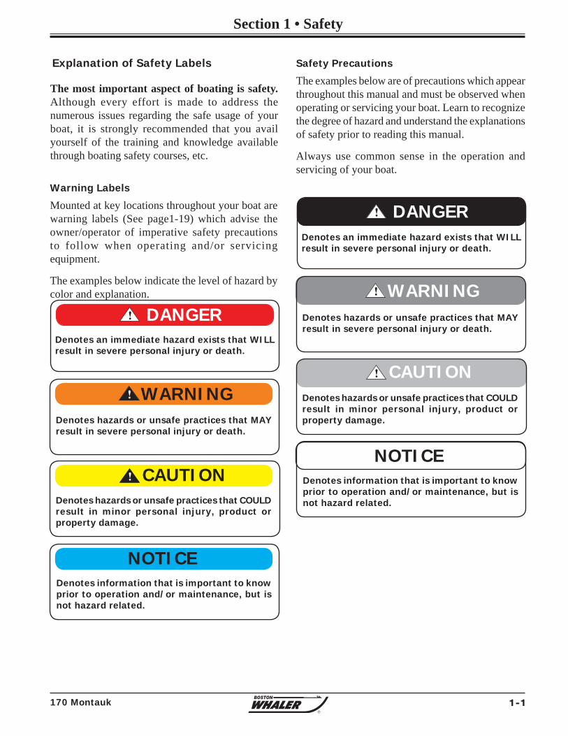
Explanation of Safety Labels
Warning Labels
Mounted at key locations throughout your boat are warning labels (See page1-19) which advise the owner/operator of imperative safety precautions to follow when operating and/or servicing equipment.
The examples below indicate the level of hazard by color and explanation.
Safety Precautions
The examples below are of precautions which appear throughout this manual and must be observed when operating or servicing your boat. Learn to recognize the degree of hazard and understand the explanations of safety prior to reading this manual.
Always use common sense in the operation and servicing of your boat.
! DANGERDenotes an immediate hazard exists that WILL result in severe personal injury or death.
Denotes information that is important to know prior to operation and/or maintenance, but is not hazard related.
NOTICE
! DANGERDenotes an immediate hazard exists that WILL result in severe personal injury or death.
Denotes hazards or unsafe practices that MAY result in severe personal injury or death.
Denotes information that is important to know prior to operation and/or maintenance, but is not hazard related.
!
Denotes hazards or unsafe practices that COULD result in minor personal injury, product or property damage.
! CAUTION
NOTICE
WARNING
The most important aspect of boating is safety. Although every effort is made to address the numerous issues regarding the safe usage of your boat, it is strongly recommended that you avail yourself of the training and knowledge available through boating safety courses, etc.
1-2 170 Montauk
Section 1• Safety
R
Boat position-secure on trailer Tiedowns-tight Winch-locked Trailer hitch-connected Safety chains-attached Swing tongue-secured with safety clip Engine clearance-in trailering position (See engine manual for recommended
guidelines) Electrical-Lights, brake lights, turn signals
working Mirrors-adjusted for trailering
SAFE Boating means: • Knowing the limitations of your boat • Following the “RULES of the ROAD” • Keeping a sharp lookout for people and objects in the water. • Not boating in water or weather conditions that are beyond the boat’s and operator’s capability. • Never operating the boat while under the infl uence of drugs or alcohol. • Being aware of your passengers safety at all times. • Reducing speed when there is limited visibility, rough water, people in the water nearby, boats or structures.
In Addition:
• Maintain your boat and its safety and other systems as recommended in this manual.
• Have the boat inspected by a qualified mechanic or dealer, at least annually.
• Ensure that the Coast Guard required safety equipment is on board and functioning.
Boating in beautiful weather and calm water conditions can be a wonderful experience. Boating however requires considerably greater skills than operating a land vehicle. Taking a boating course is the best way to prepare for a safe and enjoyable experience on the water.
• Take a Coast Guard, U.S. Power Squadron or equivalent boating safety course. (Call the Boat/U.S. Foundation at 1-800 336-2628 for information on available courses, or go to: “www.boatus.com/foundation” on the internet.)
• Get hands-on training on how to operate your boat properly.
Update checklists when equipment is added or modifi ed.
Weather-forecast safe Required documents-on board Navigation charts & equipment-on board Safety equipment-on board Safety training-passengers & crew instructed
on procedures, location, and use of safety equipment.
Drain plugs-installed Bilge pumps-working & clean Navigation lights-working Sound signal device on board Fuel system-no leaks or fumes Power steering fl uid-fi lled (if applicable) Steering system-working smoothly & properly Battery-electrolyte level within range Float plan-fi led with friend or relative
Safe Boating Checklist
Before Departure
Trailering (if applicable)
After Return
PFD’s & other safety gear-dry, stowed for next use Fuel tanks-fi lled (allow for expansion) to prevent condensation Fuel system-no leaks Bilge pump-operating properly Bilge-clean, no leaks Float plan-notify person with whom you fi led plan
As a boat owner or operator, YOU are responsible for your safety and the safety of your passengers and other boaters.
NOTICE
1-3170 Montauk
Section 1 • Safety
R
General Considerations
• Know how your boat handles under different conditions. Recognize your limitations and the boat’s limitations. Modify speed in keeping with weather, sea and traffi c conditions.
• Instruct passengers on location and use of safety equipment and procedures.
• Instruct passengers on the fundamentals of operating your boat in case you are unable to do so.
• You are responsible for passenger’s actions. If they place themselves or the boat in danger, immediately correct them.
• Remember the “Rule of Thirds”: one third total fuel usage for the trip out; one third total fuel sage while out; one third total fuel usage for the return trip.
Maintain ControlOn the water there are no marked traffi c lanes, no traffi c signs or lights, and boats have no turn signals. The boat operator must keep her or his attention focused not only on what’s ahead but what’s on the left, right and behind the boat.
The operator must always be alert to approaching boats (from the rear, right and left sides, as well as those ahead). There can be people in the water, partially submerged debris, and other navigational hazards such as rocks, sand bars or dangerous currents, to name a few.
Your passengers are relying on you to operate and maneuver the boat safely so that they are not in danger of going overboard. If you turn too quickly, increase or decrease speed abruptly, your passengers are at risk of being thrown overboard or thrown about the boat.
When visibility becomes impaired because of weather, time of day or high bow angle you must slow down so that you have suffi cient time to react if an emergency occurs. Nearby boats face similar risks in avoiding a collision with you.
Boarding
• Board only one person at a time. • Never jump into boat. Step or climb into
cockpit. • Load gear after you are aboard. Carrying
gear while boarding can cause you to lose balance.
• Distribute weight evenly. • Instruct passengers where to sit during
on-p lane opera t ion to reduce the possibility of falling overboard during high speed maneuvers.
• If gear is not immediately needed, stow it in secure areas.
• Safety gear must be immediately accessible at all times.
A qualifi ed operator must be in control of the boat at all times. Do not operate the boat while under the infl uence of alcohol or drugs. never operate your boat at speeds which exceed the operator’s ability to react if an emergency develops. At night, turn on the appropriate navigation lights and cruise at a reduced speed that will allow you plenty of time to avoid dangerous situations.
! WARNING
The detrimental effects of alcohol and drugs are increased by wind, waves and sun, and will decrease your response time and ability to act in critical situations. Give special attention to the effects of alcohol and drugs while boating. No other single factor causes as many marine accidents and deaths. Death or serious injury and damage to personal and private property can result from being impaired while operating a boat.
Impaired Operation
CONTROL HAZARD-Federal laws prohibit operating a boat while under the infl uence of alcohol or drugs. These laws are vigorously enforced.
! WARNING
1-4 170 Montauk
Section 1• Safety
R
STABILITY HAZARD • Load boat properly. The manufacturer’s load rating is the maximum allowed under normal conditions. Adjust downward if weather, water or other conditions are adverse.
• Allow passengers to ride only in areas that do not pose a hazard to themselves or the boat.
DO NOT allow passengers to ride on the bow of a closed bow boat.
DO NOT allow several passengers to ride in the bow of a small open-bow boat, causing the boat to “plow” into the water.
DO NOT allow passengers to ride on the stern cushion or gunwales.
DO NOT overload the stern.
• Observe manufacturer’s recommended on-plane seating locations.
• Passengers should remain seated while boat is moving.
PERSONAL INJURY HAZARD-Stay alert. Use of drugs, alcohol, or other substances which impair judgement poses a serious threat to yourself and others. The boat operator is responsible for the behavior of passengers.
DROWNING HAZARD-Boats must carry one wearable personal fl otation device (PFD) for every passenger on board. Boats must have at least one throwable life preserver.
SLIPPING HAZARD-Wet decks are slippery. Wear proper footwear and use extreme caution on wet surfaces.
! WARNING
Death or serious injury can result if you fail toobserve these safety rules:
• Anyone who controls the boat should have taken a boating safety course and have trained in the proper operation of the boat.
• Always operate the boat at speeds that will not put people or property in danger.
• Be constantly aware of conditions in all directions when underway and before turning.
• Reduce speed, use a lookout to identify possible hazards or diffi culties, and turn on navigation lights when:
- visibility is impaired;
- in rough water; and
- in congested waterways.
• Watch your wake. It can capsize a small boat or damage moored boats or other property. You are responsible for damage caused by your wake.
! WARNING
NEVER operate a boat at a speed at which you do not feel in control.
! WARNING
1-5170 Montauk
Section 1 • Safety
R
Legally Mandated Equipment(Minimum Required)
Consult your national and state boating law enforcement agency.
The following equipment is the minimum required by the U.S. Coast Guard for a boat less than 26’ (7.9 meters) in length.
• One (1) Coast Guard approved Type I, II or III PFD for each person aboard or being towed on water skis, tubes, etc.
Fire Extinquisher (Portable)
It is recommended that you carry one (1) A, B or C Type fi re extinguisher on board and located near the helm for easy reach.
Personal Flotation Devices (PFD’s)
FIRE EXTINGUISHER LOCATION
A storage pocket for the portable fi re extinguisher is located on the lower starboard side of the center console.
Depending on the state or country of operation, the operator of a vessel may be fi ned for failure to comply with local or national rules regarding PFD usage.
NOTICE
Visual distress Signals
Boats operating in coastal waters, the Great Lakes & US owned boats on the high seas are required to carry approved visual distress signals for nighttime use. They must be readily accessible, in serviceable condition and not be expired.
Store all pyrotechnic signals in a well marked, waterproof container.
Additional Recommended equipment for safe operationIn addition to the legally mandated equipment, the following items are recommended for safe boating.
• First Aid kit • Compass • Charts/Maps • Manual bilge pump• Visual distress signals • GPS or LORAN (for day or night use) • Spare keys• Marine VHF radio • EPIRB-Emergency• Moisture repellent positioning-indicat-• Mooring Lines ing radio beacon• Fenders • Boat hook• Waterproof fl ashlights • Extra batteries• High power spotlight • Instruction manuals• Spare propeller • Lubricating oil• Tool kit: - Screwdrivers, (phillips & fl at) - Pliers, (regular, vise-grip, tongue & groove) - Wrenches, (box, open end, allen & adjustable) - Socket set, (metric and U.S.) - Electrical tape & duct tape - Hammer - Spare parts kit, (spark plugs, fuses, etc.)
There is rarely time to reach stowed life jackets in time of emergency. Boaters should always wear a properly fi tting, approved life jacket when on the water.
Children and non-swimmers MUST wear PFDs at all times when aboard.
! WARNING
Whistle, Horn
You must have on board, some means of making a loud sound signal. Navigation rules require that a sound made by any audible device be capable of a four (4) second blast, and must be audible for 1/2 mi. (.80 Km).

1-6 170 Montauk
Section 1• Safety
R
Carbon Monoxide is an oderless, colorless, and tasteless, extremely toxic gas produced by engines, heaters, stoves or generators. When inhaled it combines with hemoglobin in the blood, preventing absorption of oxygen and is unlikely to be noticed until the person is overcome.
Prolonged exposure to low concentration or very short exposure to high concentrations can result in asphyxiation and death.
Symptoms of Carbon Monoxide poisoning include: • Dizziness • Headaches • Ringing in the ears • Nausea • UnconsiousnessGET MEDICAL ATTENTION AS SOON AS POSSIBLE.
Symptoms of CO poisoning are often confused with seasickness or intoxication, so those affected may not receive the medical attention they need.
The poisoning victim’s skin often turns cherry red. If CO poisoning is suspected, have the victim breath fresh air deeply. If breathing stops, resusitate. A victim often revives, then relapses because organs are damaged by lack of oxygen.
Carbon Monoxide (CO)
• Fumes from the engine(s), Generator(s) and other equipment and appliances that burn fuel contain Carbon Monoxide. Carbon Monoxide can kill you. Open all doors, hatches, curtains and windows to allow fresh air to circulate and dissipate the amounts of Carbon Monoxide present in enclosed spaces, especially when the boat is moored or anchored.
• Proper ventilation must be maintained, even during inclement weather to prevent dangerous levels of Carbon Monoxide build-up.
• Sleeping aboard a boat will require a working Carbon monoxide detection system, preferably in each sleeping quarter.
! DANGER
Carbon Monoxide can accumulate in dangerous concentrations anywhere in or around your boat including on back decks, swim platforms, or in water around exhausts. CO can remain in or around your boat at dangerus levels even if your engine is no longer running.
Remember: • If you can smell engine exhaust, you are
inhaling CO.
• Changing course and speed to place boat heading into the wind can improve ventilation.
To minimize the danger of Carbon Monoxide accumulation when the Engine is running (or by use of fuel burning equipment.):
• Do not idle the engine without moving the boat for more than 15 minutes at a time.
• Inspect the exhaust system regularly.
• Operate all fuel burning appliances, such as charcoal, propane, LPG, CNG or alcohol cooking devices in areas where fresh air can circulate.
! DANGERNever ignore an alarm.
In the event the CO alarm activates:
• Evacuate enclosed areas immediately.
• Shut OFF any fuel burning equipment or appliances.
• Open hatches, doors, portlights, etc. to improve ventilation.
• If making way, head boat into the wind.
1-7170 Montauk
Section 1 • Safety
R
170 Montauk
R
170 Montauk
R
170 Montauk
R
170 Montauk
R
170 Montauk
R
PFD Classifi cations
Listed below are the several different types of PFDs, each life jacket has different purposes, choose one that will suit your purpose.
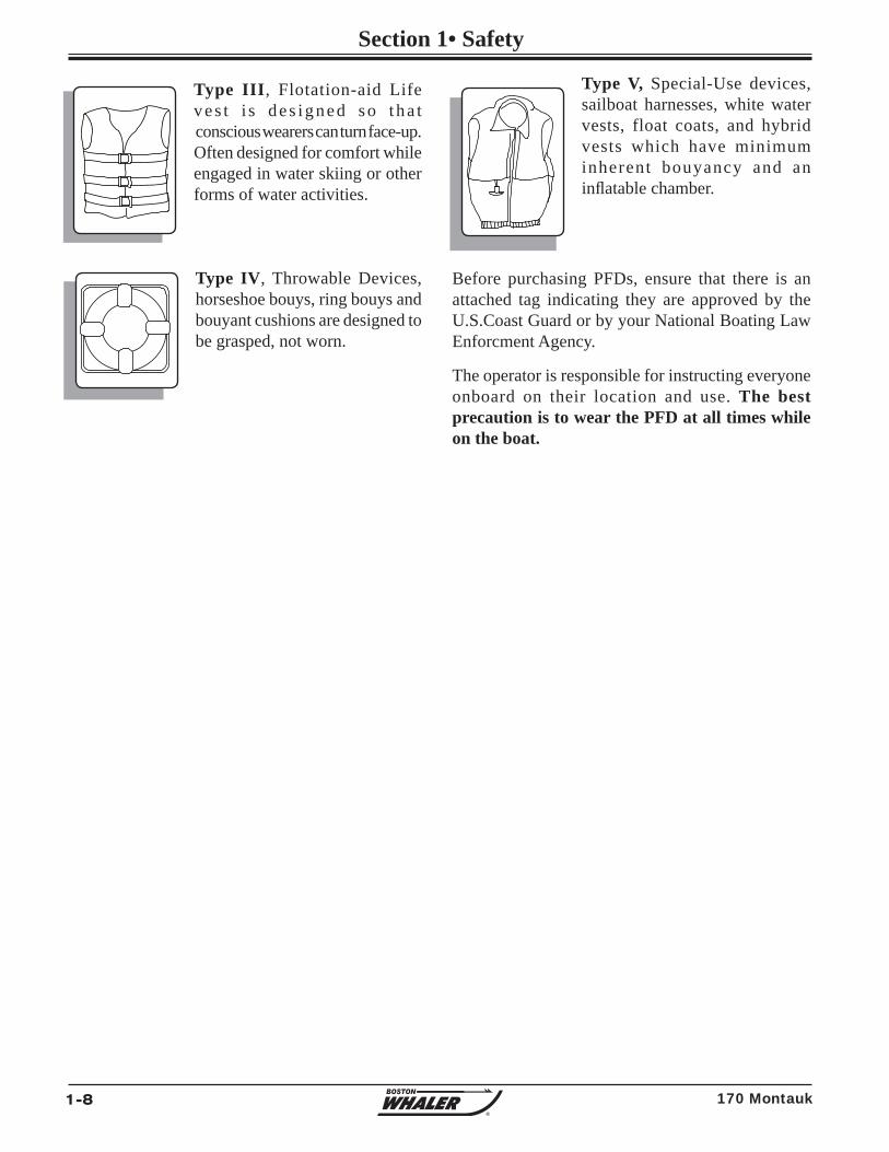
Type I, Off-shore Life Jacket is considered the most bouyant, it is designed to turn an unconscious person face up. Use in all types of waters where rescue may be slow, particularly in cold or rough water conditions.
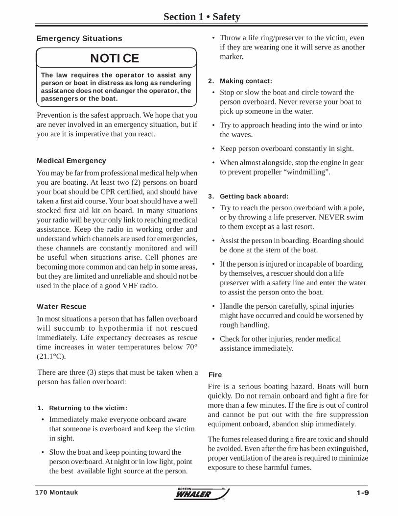
Type II, Near-shore Life Vest, “keyhole” vest with flotation fi lled head and neck support is also designed to turn a person face up, but the turning action is not as pronounced. Use in calm inland waters or where quick rescue is likely.
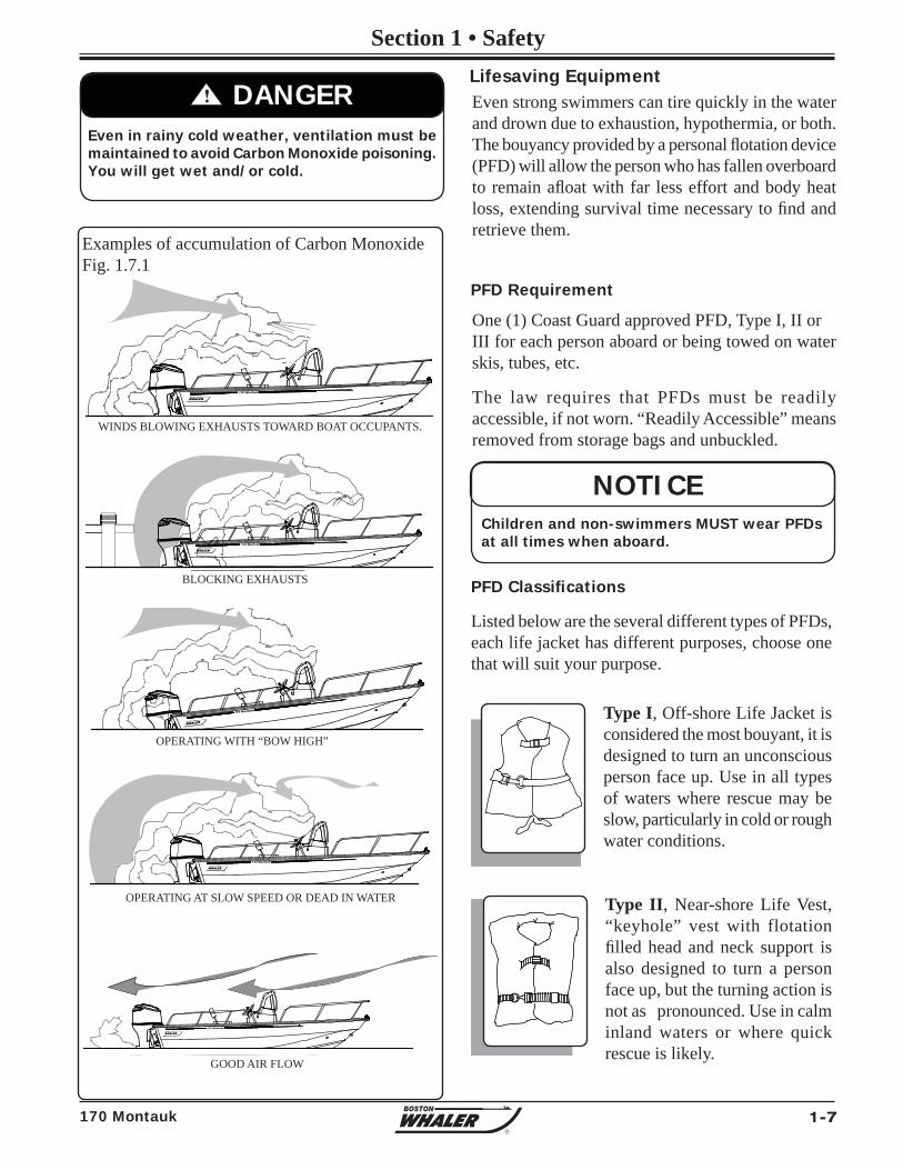
! DANGEREven in rainy cold weather, ventilation must be maintained to avoid Carbon Monoxide poisoning. You will get wet and/or cold.
Examples of accumulation of Carbon MonoxideFig. 1.7.1
Even strong swimmers can tire quickly in the water and drown due to exhaustion, hypothermia, or both. The bouyancy provided by a personal fl otation device (PFD) will allow the person who has fallen overboard to remain afl oat with far less effort and body heat loss, extending survival time necessary to fi nd and retrieve them.
One (1) Coast Guard approved PFD, Type I, II or III for each person aboard or being towed on water skis, tubes, etc.
The law requires that PFDs must be readily accessible, if not worn. “Readily Accessible” means removed from storage bags and unbuckled.
Lifesaving Equipment
PFD Requirement
Children and non-swimmers MUST wear PFDs at all times when aboard.
NOTICE
BLOCKING EXHAUSTS
GOOD AIR FLOW
OPERATING AT SLOW SPEED OR DEAD IN WATER
WINDS BLOWING EXHAUSTS TOWARD BOAT OCCUPANTS.
OPERATING WITH “BOW HIGH”
1-8 170 Montauk
Section 1• Safety
R
Type V, Special-Use devices,sailboat harnesses, white watervests, float coats, and hybridvests which have minimum inherent bouyancy and an infl atable chamber.
Before purchasing PFDs, ensure that there is an attached tag indicating they are approved by the U.S.Coast Guard or by your National Boating Law Enforcment Agency.
The operator is responsible for instructing everyone onboard on their location and use. The best precaution is to wear the PFD at all times while on the boat.
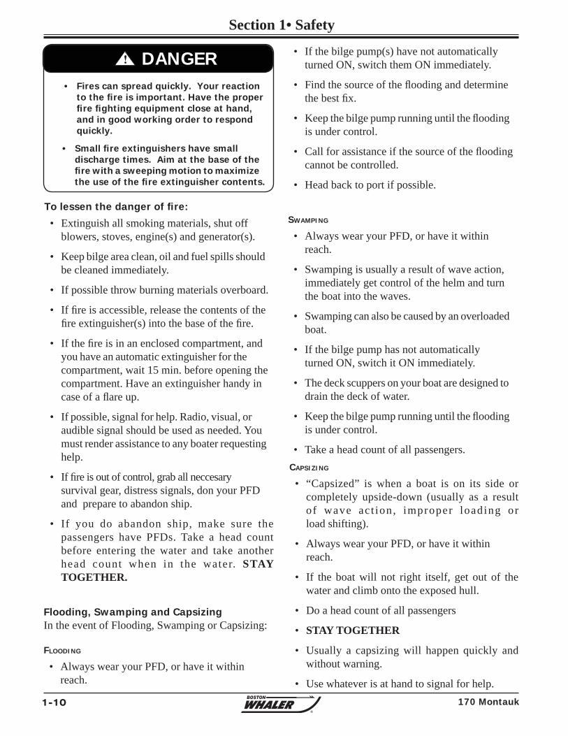
Type III, Flotation-aid Life ve s t i s de s igned so t ha t conscious wearers can turn face-up. Often designed for comfort while engaged in water skiing or other forms of water activities.
Type IV, Throwable Devices, horseshoe bouys, ring bouys and bouyant cushions are designed to be grasped, not worn.
1-9170 Montauk
Section 1 • Safety
R
There are three (3) steps that must be taken when a person has fallen overboard:
1. Returning to the victim:
• Immediately make everyone onboard aware that someone is overboard and keep the victim in sight.
• Slow the boat and keep pointing toward the person overboard. At night or in low light, point the best available light source at the person.
Prevention is the safest approach. We hope that you are never involved in an emergency situation, but if you are it is imperative that you react.
Medical Emergency
You may be far from professional medical help when you are boating. At least two (2) persons on board your boat should be CPR certifi ed, and should have taken a fi rst aid course. Your boat should have a well stocked fi rst aid kit on board. In many situations your radio will be your only link to reaching medical assistance. Keep the radio in working order and understand which channels are used for emergencies, these channels are constantly monitored and will be useful when situations arise. Cell phones are becoming more common and can help in some areas, but they are limited and unreliable and should not be used in the place of a good VHF radio.
Water Rescue
In most situations a person that has fallen overboard will succumb to hypothermia if not rescued immediately. Life expectancy decreases as rescue time increases in water temperatures below 70° (21.1°C).
Emergency Situations • Throw a life ring/preserver to the victim, even if they are wearing one it will serve as another marker.
2. Making contact:
• Stop or slow the boat and circle toward the person overboard. Never reverse your boat to pick up someone in the water.
• Try to approach heading into the wind or into the waves.
• Keep person overboard constantly in sight.
• When almost alongside, stop the engine in gear to prevent propeller “windmilling”.
3. Getting back aboard:
• Try to reach the person overboard with a pole, or by throwing a life preserver. NEVER swim to them except as a last resort.
• Assist the person in boarding. Boarding should be done at the stern of the boat.
• If the person is injured or incapable of boarding by themselves, a rescuer should don a life preserver with a safety line and enter the water to assist the person onto the boat.
• Handle the person carefully, spinal injuries might have occurred and could be worsened by rough handling.
• Check for other injuries, render medical assistance immediately.
Fire is a serious boating hazard. Boats will burn quickly. Do not remain onboard and fi ght a fi re for more than a few minutes. If the fi re is out of control and cannot be put out with the fi re suppression equipment onboard, abandon ship immediately.
The fumes released during a fi re are toxic and should be avoided. Even after the fi re has been extinguished, proper ventilation of the area is required to minimize exposure to these harmful fumes.
Fire
The law requires the operator to assist any person or boat in distress as long as rendering assistance does not endanger the operator, the passengers or the boat.
NOTICE
1-10 170 Montauk
Section 1• Safety
R
CAPSIZING
• “Capsized” is when a boat is on its side or completely upside-down (usually as a result of wave ac t ion , improper loading or load shifting).
• Always wear your PFD, or have it within reach.
• If the boat will not right itself, get out of the water and climb onto the exposed hull.
• Do a head count of all passengers
• STAY TOGETHER
• Usually a capsizing will happen quickly and without warning.
• Use whatever is at hand to signal for help.
• Fires can spread quickly. Your reaction to the fi re is important. Have the proper fi re fi ghting equipment close at hand, and in good working order to respond quickly.
• Small fi re extinguishers have small discharge times. Aim at the base of the fi re with a sweeping motion to maximize the use of the fi re extinguisher contents.
! DANGER
Flooding, Swamping and CapsizingIn the event of Flooding, Swamping or Capsizing:
FLOODING
• Always wear your PFD, or have it within reach.
To lessen the danger of fi re:
• Extinguish all smoking materials, shut off blowers, stoves, engine(s) and generator(s).
• Keep bilge area clean, oil and fuel spills should be cleaned immediately.
• If possible throw burning materials overboard.
• If fi re is accessible, release the contents of the fi re extinguisher(s) into the base of the fi re.
• If the fi re is in an enclosed compartment, and you have an automatic extinguisher for the compartment, wait 15 min. before opening the compartment. Have an extinguisher handy in case of a fl are up.
• If possible, signal for help. Radio, visual, or audible signal should be used as needed. You must render assistance to any boater requesting help.
• If fi re is out of control, grab all neccesary survival gear, distress signals, don your PFD and prepare to abandon ship.
• If you do abandon ship, make sure the passengers have PFDs. Take a head count before entering the water and take another head count when in the water. STAY TOGETHER.
• If the bilge pump(s) have not automatically turned ON, switch them ON immediately.
• Find the source of the fl ooding and determine the best fi x.
• Keep the bilge pump running until the fl ooding is under control.
• Call for assistance if the source of the fl ooding cannot be controlled.
• Head back to port if possible.
SWAMPING
• Always wear your PFD, or have it within reach.
• Swamping is usually a result of wave action, immediately get control of the helm and turn the boat into the waves.
• Swamping can also be caused by an overloaded boat.
• If the bilge pump has not automatically turned ON, switch it ON immediately.
• The deck scuppers on your boat are designed to drain the deck of water.
• Keep the bilge pump running until the fl ooding is under control.
• Take a head count of all passengers.
1-11170 Montauk
Section 1 • Safety
R
steering is virtually useless. If you are in a congested waterway you will need to react quickly to warn others that you have lost power, propulsion or steering control and that assistance will be needed.
Grounding
Running aground may be avoided by paying attention to marker bouys or observing the waves as they form into breakers when passing over a sand bar.
If you do run aground, the course of action depends on how hard the boat hits bottom and whether the boat remains stranded. If it is a simple touch, you may need only to inspect the lower drive of the engine and the hull of the boat. If possible do a thorough inspection before trying to get loose, throwing the boat into reverse before this is done may do more damage.
Distress Signals
VISUAL DISTRESS SIGNALS, (VDS)
• U.S. Coast Guard regulations require boats in coastal waters and the Great Lakes to carry a Visual Distress Signal (VDS) for day and night use, as well as appropriate for the time of operation. Exempt from the day signals requirement, but not night signals, are boats less than 16 feet (4.8 m), open sailboats less than 26 feet (7.9m), boats participating in organized events and manually propelled boats.
• If you are required to have visual distress signals, at least three safety approved pyrotechnic devices in serviceable condition must be readily accessible. They must be marked with a date showing the service life which must not be expired.
• Carry three signals for day use and three for night use. Some pyrotechnic devices such as red fl ares, meet both day and night use requirements.
• Store pyrotechnic signals in a cool, dry location. An orange or red watertight container prominently marked “DISTRESS SIGNALS” is recommended.
The chances of fl ooding, swamping or capsizing can be reduced by being aware of: • Weather
• Water Conditions
• Proper boat handling techniques
• Proper loading of the boat
CollisionIn the event of collision: • Cut the engine(s)
• Always wear your PFD, or have it within reach.
• Check on passengers
• If the bilge pump has not automatically turned ON, switch it ON immediately.
• Determine the amount of damage to your boats structure.
• Call for assistance
• In the event of collision you are required to fi le an accident report. Contact a state enforcement agency or the nearest U.S. Coast Guard offi ce. If you are boating outside U.S. waters, consult the nation you are visiting for accident reporting requirements.
Propulsion, Control or Steering failureIf there is a propulsion, control or steering failure: • Stop the engine, (shut off at Ignition or pull on the Emergency Engine Shut-Off Switch.)
• Drop anchor to prevent drifting.
• Determine if the problem can be fi xed or will assistance be needed.
• Call for assistance if needed
When loss of propulsion or steering is noticed, your quick reaction is required to prevent further damage to your boat or injuries to your passengers.
Outboard engines require propulsion to control the direction the boat will take. Without propulsion, the
1-12 170 Montauk
Section 1• Safety
R
Other recognized visual distress signals include: • Flames in a bucket
• Code flags November & Charlie displayed together.
• Black square & ball on orange background fl ag
• Orange fl ag (certifi ed)
• Electric distress light (certifi ed)-for night use
• Dye marker (any color)
• Person waving arms (slowly)
• U.S. ensign fl own upside down
AUDIBLE DISTRESS SIGNALS, (ADS)U.S. Coast Guard regulations require one hand, mouth or power operated whistle or horn, audible for at least 1/2 mile.
Other recognized audible distress signals include: • Radio communication (see Radio Communication below)
• Radio-telegraph/telephone alarm
• Position indicating radio beacon (EPIRB)
• Morse Code S-O-S (3 short 3 long 3 short) sounded by any means.
• Fog horn sounded continuously.
Radio CommunicationA radio is the boat operator’s main method of recieving safety information and summoning aid. VHF-FM radio is the primary means of short range communication. Single sideband radio (SSB) is used for longer range communication.
VHF-FM channel 16 and SSB 2182 kHz are designated for emergency use. Such situations can be categorized as:
• EMERGENCY- “MAYDAY, MAYDAY, MAYDAY,”- used when life or vessel is in imminent danger.
• URGENCY- “PAN-PAN, PAN-PAN, PAN-PAN” (pronounced PAHN-PAHN)-used when a person or vessel is in some jeopardy less than indicated by a “MAYDAY” call.
• SAFETY- “SECURITY, SECURITY, SECURITY” (pronounced SAY-CURE-IT-AY)-used for navigational safety or weather warning.
An emergency situation will be hectic and there will not be time to learn proper radio procedure. LEARN WHAT TO DO BEFORE YOU NEED TO DO IT. If you hear a distress call, stop all radio transmissions. If you can directly assist, respond on the emergency frequency. If you cannot assist, do not transmit on that frequency. However, continue to monitor until it is obvious that help is being provided.
Weather
Getting caught in severe weather is hazardous. Bad weather and/or rough sea or water conditions can cause an unsafe situation. Consult local weather services for up-to-date forecasts on weather and sea conditions. Television, Radio, Internet can give you access to NOAA weather reports that will help you make a determination on where and when to get underway. Following are some weather related rules:
• Understand the design limitations of your boat.
• Check the weather forecast and water conditions before leaving and while underway.
• Wear a Personal Flotation Device, (PFD).
DO NOT attempt to boat in severe weather conditions. Death or serious injury can occur. Get to shore before the weather turns bad.
! DANGER
1-13170 Montauk
Section 1 • Safety
R
A sudden change in wind direction or speed or an increase in wave height indicates deteriorating weather.
! WARNING
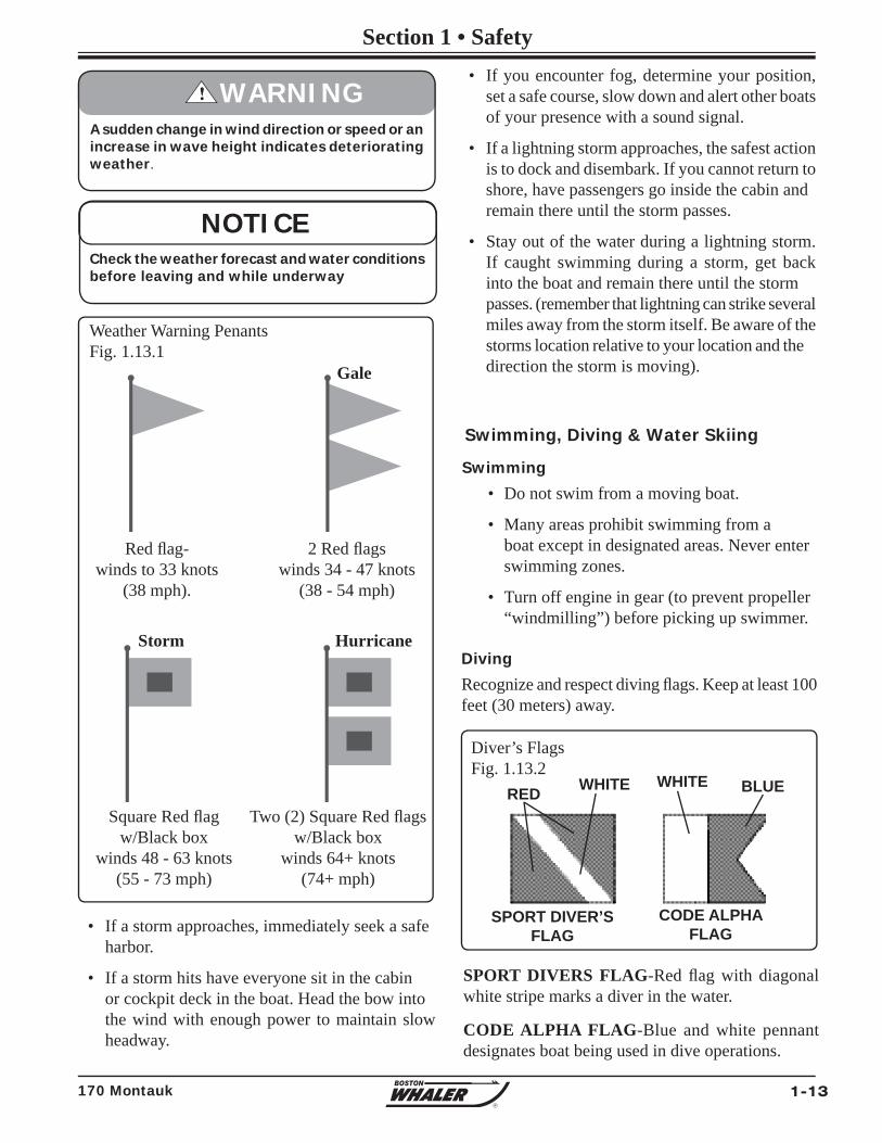
2 Red fl agswinds 34 - 47 knots
(38 - 54 mph)
Weather Warning PenantsFig. 1.13.1
• If a storm approaches, immediately seek a safe harbor.
• If a storm hits have everyone sit in the cabin or cockpit deck in the boat. Head the bow into the wind with enough power to maintain slow headway.
Swimming, Diving & Water Skiing
Swimming
• Do not swim from a moving boat.
• Many areas prohibit swimming from a boat except in designated areas. Never enter swimming zones.
• Turn off engine in gear (to prevent propeller “windmilling”) before picking up swimmer.
SPORT DIVERS FLAG-Red fl ag with diagonal white stripe marks a diver in the water.
CODE ALPHA FLAG-Blue and white pennant designates boat being used in dive operations.
Diving
Recognize and respect diving fl ags. Keep at least 100 feet (30 meters) away.
Diver’s FlagsFig. 1.13.2
RED WHITE BLUE
CODE ALPHA FLAG
SPORT DIVER’S FLAG
WHITE
• If you encounter fog, determine your position, set a safe course, slow down and alert other boats of your presence with a sound signal.
• If a lightning storm approaches, the safest action is to dock and disembark. If you cannot return to shore, have passengers go inside the cabin and remain there until the storm passes.
• Stay out of the water during a lightning storm. If caught swimming during a storm, get back into the boat and remain there until the storm passes. (remember that lightning can strike several miles away from the storm itself. Be aware of the storms location relative to your location and the direction the storm is moving).
Red fl ag-winds to 33 knots
(38 mph).
Gale
Square Red fl agw/Black box
winds 48 - 63 knots(55 - 73 mph)
Storm
Two (2) Square Red fl agsw/Black box
winds 64+ knots(74+ mph)
Hurricane
Check the weather forecast and water conditions before leaving and while underway
NOTICE
1-14 170 Montauk
Section 1• Safety
R
Water Skiing Signals
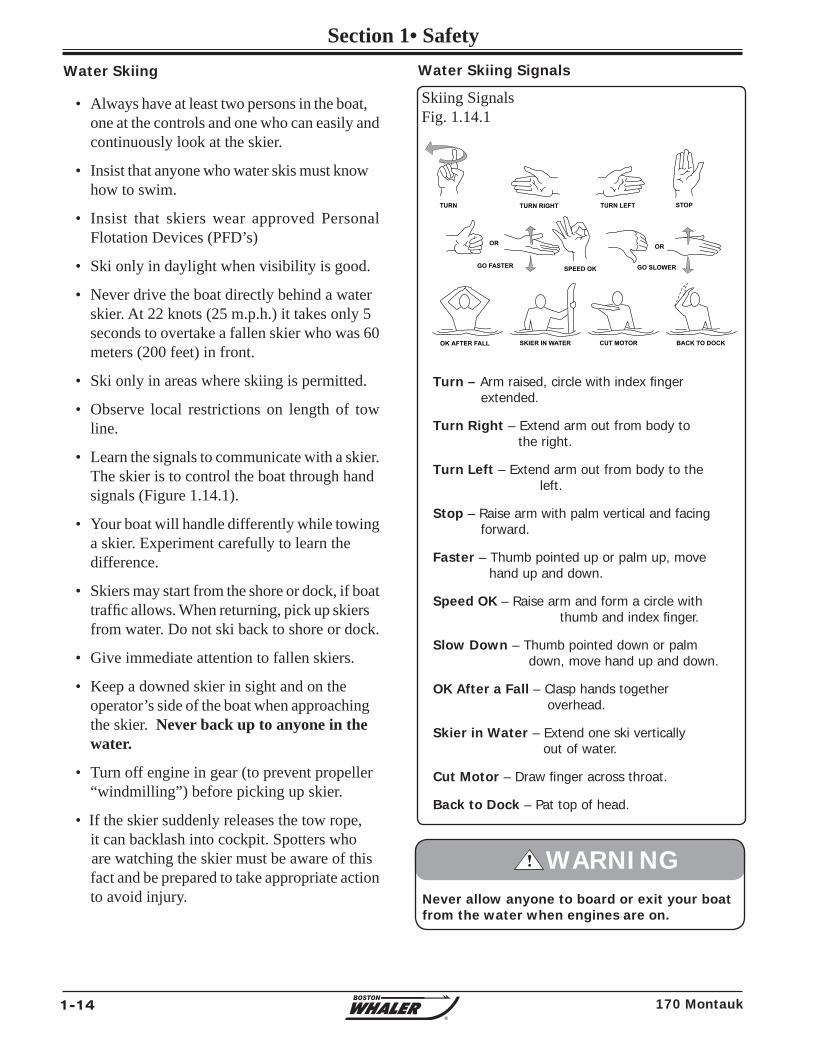
Turn – Arm raised, circle with index fi nger extended.
Turn Right – Extend arm out from body to the right.
Turn Left – Extend arm out from body to the left.
Stop – Raise arm with palm vertical and facing forward.
Faster – Thumb pointed up or palm up, move hand up and down.
Speed OK – Raise arm and form a circle with thumb and index fi nger.
Slow Down – Thumb pointed down or palm down, move hand up and down.
OK After a Fall – Clasp hands together overhead.
Skier in Water – Extend one ski vertically out of water.
Cut Motor – Draw fi nger across throat.
Back to Dock – Pat top of head.
• Always have at least two persons in the boat, one at the controls and one who can easily and continuously look at the skier.
• Insist that anyone who water skis must know how to swim.
• Insist that skiers wear approved Personal Flotation Devices (PFD’s)
• Ski only in daylight when visibility is good.
• Never drive the boat directly behind a water skier. At 22 knots (25 m.p.h.) it takes only 5 seconds to overtake a fallen skier who was 60 meters (200 feet) in front.
• Ski only in areas where skiing is permitted.
• Observe local restrictions on length of tow line.
• Learn the signals to communicate with a skier. The skier is to control the boat through hand signals (Figure 1.14.1).
• Your boat will handle differently while towing a skier. Experiment carefully to learn the difference.
• Skiers may start from the shore or dock, if boat traffi c allows. When returning, pick up skiers from water. Do not ski back to shore or dock.
• Give immediate attention to fallen skiers.
• Keep a downed skier in sight and on the operator’s side of the boat when approaching the skier. Never back up to anyone in the water.
• Turn off engine in gear (to prevent propeller “windmilling”) before picking up skier.
• If the skier suddenly releases the tow rope, it can backlash into cockpit. Spotters who are watching the skier must be aware of this fact and be prepared to take appropriate action to avoid injury.
Skiing SignalsFig. 1.14.1
Water Skiing
SPEED OK GO SLOWER
TURN TURN RIGHT TURN LEFT STOP
GO FASTER
SKIER IN WATEROK AFTER FALL CUT MOTOR BACK TO DOCK
OR OR
Never allow anyone to board or exit your boat from the water when engines are on.
! WARNING
1-15170 Montauk
Section 1 • Safety
R
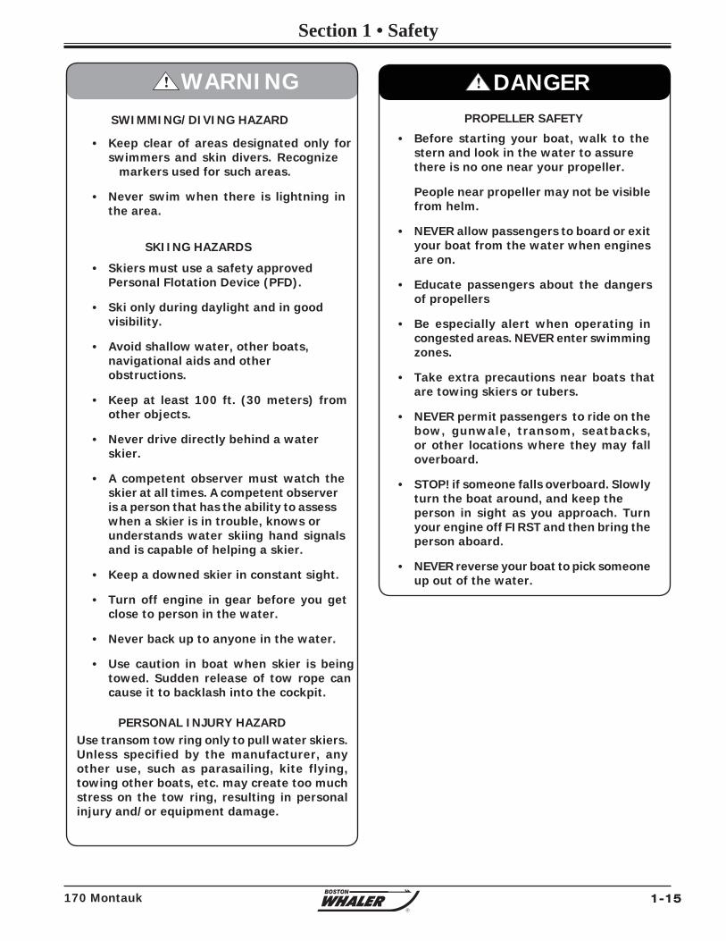
SWIMMING/DIVING HAZARD
• Keep clear of areas designated only for swimmers and skin divers. Recognize markers used for such areas.
• Never swim when there is lightning in the area.
SKIING HAZARDS
• Skiers must use a safety approved Personal Flotation Device (PFD).
• Ski only during daylight and in good visibility.
• Avoid shallow water, other boats, navigational aids and other obstructions.
• Keep at least 100 ft. (30 meters) from other objects.
• Never drive directly behind a water skier.
• A competent observer must watch the skier at all times. A competent observer is a person that has the ability to assess when a skier is in trouble, knows or understands water skiing hand signals and is capable of helping a skier.
• Keep a downed skier in constant sight.
• Turn off engine in gear before you get close to person in the water.
• Never back up to anyone in the water.
• Use caution in boat when skier is being towed. Sudden release of tow rope can cause it to backlash into the cockpit.
PERSONAL INJURY HAZARDUse transom tow ring only to pull water skiers. Unless specified by the manufacturer, any other use, such as parasailing, kite flying, towing other boats, etc. may create too much stress on the tow ring, resulting in personal injury and/or equipment damage.
! WARNING
PROPELLER SAFETY
• Before starting your boat, walk to the stern and look in the water to assure there is no one near your propeller.
People near propeller may not be visible from helm.
• NEVER allow passengers to board or exit your boat from the water when engines are on.
• Educate passengers about the dangers of propellers
• Be especially alert when operating in congested areas. NEVER enter swimming zones.
• Take extra precautions near boats that are towing skiers or tubers.
• NEVER permit passengers to ride on the bow, gunwale, transom, seatbacks, or other locations where they may fall overboard.
• STOP! if someone falls overboard. Slowly turn the boat around, and keep the person in sight as you approach. Turn your engine off FIRST and then bring the person aboard.
• NEVER reverse your boat to pick someone up out of the water.
! DANGER
1-16 170 Montauk
Section 1• Safety
R
To avoid boating in unsafe areas where there are underwater obstructions, shallow water, unnavigable conditions such as dangerous currents, and others, you must chart a course. this means having and using National Oceanic and Atmospheric Administration (NOAA) charts for coastal waters, observing and understanding all navigational aids, using the knowledge and guidence of experienced boaters, and being aware of the tides and times where appropriate. If you are boating in an area you are unfamiliar with, proceed with caution and post a lookout to watch for hazards.
Chart Your Course
Float Plan
Float plans are important to you should you encounter problems on the water. A fl oat plan should contain a description of your boat along with any distinguishing features. It should describe where you will be boating, your departure time and estimated return. The number and names of passengers, and destination should also be noted.
The fl oat plan should be given to a friend or relative, so they can give the information to a national boating agency like the U.S. Coast Guard, in the event you do not return at the time specifi ed on the fl oat plan.
If there are any changes to the fl oat plan they should be conveyed to the person holding the fl oat plan. Once you return you should contact the person holding the fl oat plan to let them know you are back.
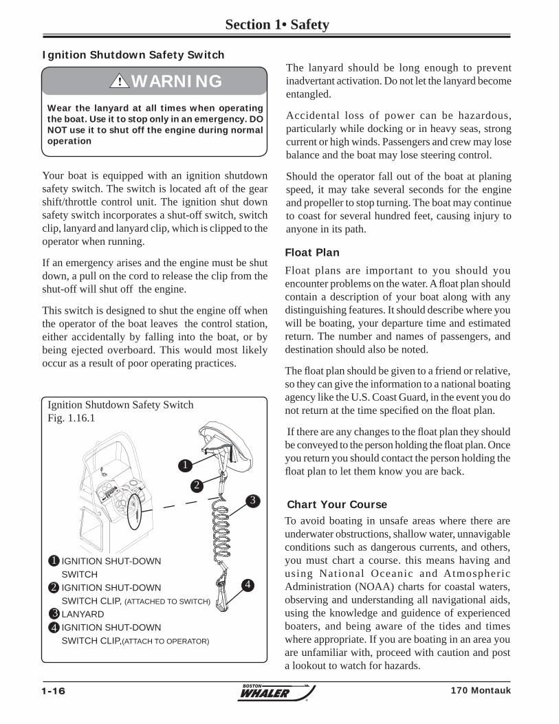
Your boat is equipped with an ignition shutdown safety switch. The switch is located aft of the gear shift/throttle control unit. The ignition shut down safety switch incorporates a shut-off switch, switch clip, lanyard and lanyard clip, which is clipped to the operator when running.
If an emergency arises and the engine must be shut down, a pull on the cord to release the clip from the shut-off will shut off the engine.
This switch is designed to shut the engine off when the operator of the boat leaves the control station, either accidentally by falling into the boat, or by being ejected overboard. This would most likely occur as a result of poor operating practices.
Ignition Shutdown Safety Switch
Wear the lanyard at all times when operating the boat. Use it to stop only in an emergency. DO NOT use it to shut off the engine during normal operation
! WARNING
IGNITION SHUT-DOWNSWITCHIGNITION SHUT-DOWNSWITCH CLIP, (ATTACHED TO SWITCH)
LANYARDIGNITION SHUT-DOWNSWITCH CLIP,(ATTACH TO OPERATOR)
Ignition Shutdown Safety SwitchFig. 1.16.1
4
1
2
43
1
4
32
The lanyard should be long enough to prevent inadvertant activation. Do not let the lanyard become entangled.
Accidental loss of power can be hazardous, particularly while docking or in heavy seas, strong current or high winds. Passengers and crew may lose balance and the boat may lose steering control.
Should the operator fall out of the boat at planing speed, it may take several seconds for the engine and propeller to stop turning. The boat may continue to coast for several hundred feet, causing injury to anyone in its path.
1-17170 Montauk
Section 1 • Safety
R
Hitting an object in or under the water or boating in dangerous currents can cause serious injury or death to occupants in the boat.
You must know where the hazards are and avoid them. In uncharted waters, boat very slowly and post a lookout.
If an object is struck or if you run aground:
• Shut the engine OFF
• Check the hull for damage
• Check the propeller(s) for damage
• If aground, consider the bottom grade before moving off, (damage to the hull and propeller(s) could be worsened).
• Determine the tides and whether it will help or hinder you from the grounding.
• Do not have anyone other than a trained and competent service tow your boat.
! WARNING
Environmental Considerations
Fuel & Oil Spillage
Regulations prohibit discharging fuel or oily waste in navigable waters. Discharge is defi ned as any action which causes a fi lm, sheen or discoloration on the water surface, or causes a sludge or emulsion beneath the water surface. A common violation is
Excessive Noise
Many areas regulate noise limits. Even if there are no laws, courtesy demands that boats operate quietly.
Wake / Wash
Power boat wakes can endanger people and vessels. Each power boat operator is responsible for injury or damage caused by the boat’s wake. Be especially careful in confi ned areas such as channels or marinas. Observe “no wake” warnings.
SPEED HAZARD - Watch your wake. It might capsize a smaller craft. You are responsible for damage caused by your wake.
! WARNING
Reduce speed in congested waterway. Be alert for No Wake markers.
! WARNING
bilge discharge. Use rags or sponges to soak up fuel or oily waste, then dispose of it properly ashore. If there is much fuel or oil in the bilge, contact a knowledgeable marine service to remove it. Never pump contaminated bilge overboard. Help protect your waters.
1-18 170 Montauk
Section 1• Safety
R
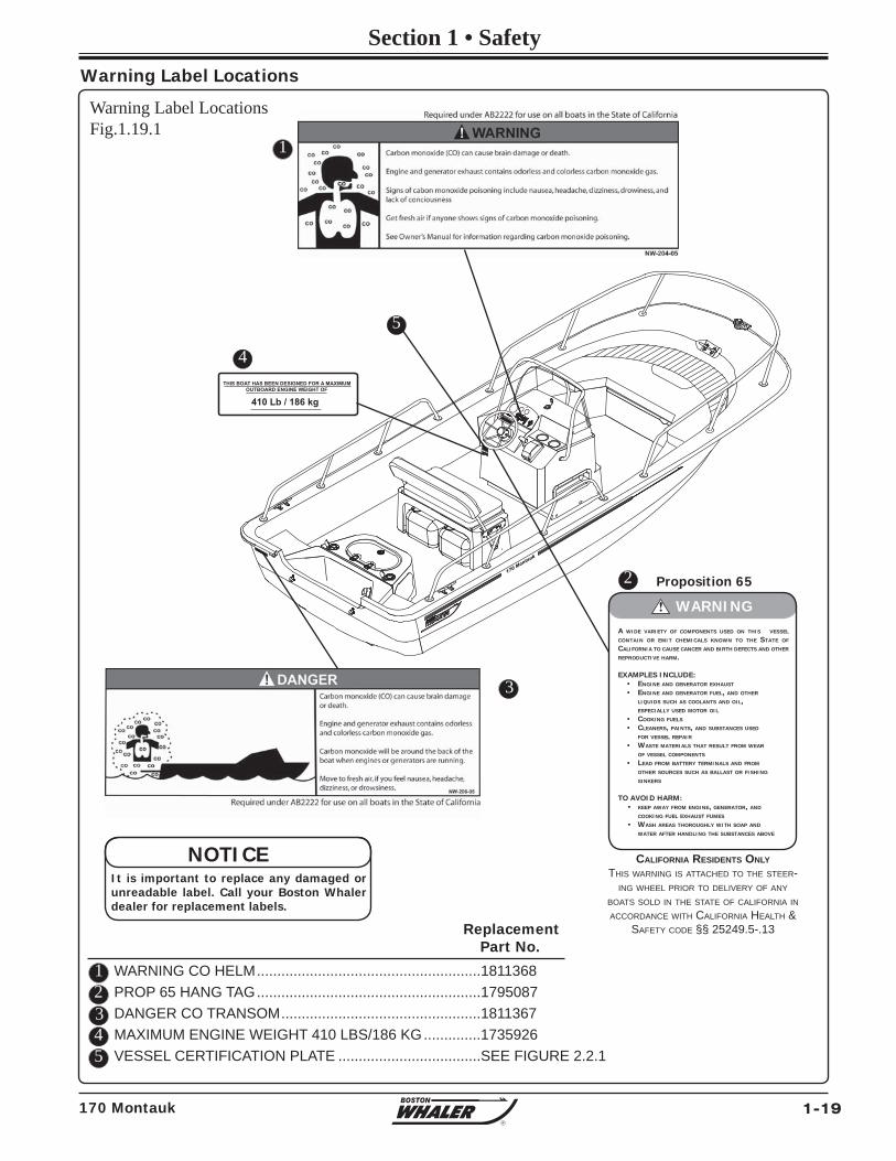
Mounted at key locations throughout the boat (See fi gure 1.19.1), warning labels advise the owner/operator of imperative safety precautions to follow when operating and/or servicing equipment. DO NOT REMOVE OR OBSTRUCT ANY WARNING LABEL. Replace any label which becomes illegible.
Warning Label Locations
Homeland Security restrictionsRecreational boaters have a role in keeping our waterways safe and secure. Violators of the restrictions below can expect a quick and severe response.
• DO NOT approach within 100 yards, and slow to minimum speed within 500 yards of any U.S. Naval vessel. If you need to pass within 100 yards of a U.S. Naval vessel for safe passage, you must contact the U.S. Naval vessel or the Coast Guard escort vessel on VHF-FM channel 16.
• Observe and avoid all security zones. Avoid commercial port areas, especially those that involve military, cruise line or petroleum facilities. Observe and avoid other restricted areas near dams, power plants, etc.
• DO NOT stop or anchor beneath bridges or in channels.
America’s Waterway WatchIn March, 2005, the U.S. Coast Guard offi cially launched America’s Waterway Watch to encourage the boating public to report suspicious activities in our nation’s ports and waterways. America’s Waterway Watch simply asks anyone who works, lives, or recreates on the water to keep an eye out for suspicious activities. Anyone who spots such activity is asked to call the National Response Center’s 24-hour hotline, 800-424-8802 or 877-24WATCH (877-249-2824).
DO NOT approach within 100 yards of any U.S. Naval vessel without fi rst contacting the vessel on VHF-FM channel 16. To do so will result in a quick and severe response.
! DANGER
1-19170 Montauk
Section 1 • Safety
R
Warning Label Locations
Proposition 65
CALIFORNIA RESIDENTS ONLY THIS WARNING IS ATTACHED TO THE STEER-
ING WHEEL PRIOR TO DELIVERY OF ANY BOATS SOLD IN THE STATE OF CALIFORNIA IN ACCORDANCE WITH CALIFORNIA HEALTH &
SAFETY CODE §§ 25249.5-.13
A WIDE VARIETY OF COMPONENTS USED ON THIS VESSEL CONTAIN OR EMIT CHEMICALS KNOWN TO THE STATE OF CALIFORNIA TO CAUSE CANCER AND BIRTH DEFECTS AND OTHER REPRODUCTIVE HARM.
EXAMPLES INCLUDE: • ENGINE AND GENERATOR EXHAUST
• ENGINE AND GENERATOR FUEL, AND OTHER LIQUIDS SUCH AS COOLANTS AND OIL, ESPECIALLY USED MOTOR OIL
• COOKING FUELS
• CLEANERS, PAINTS, AND SUBSTANCES USED FOR VESSEL REPAIR
• WASTE MATERIALS THAT RESULT FROM WEAR OF VESSEL COMPONENTS
• LEAD FROM BATTERY TERMINALS AND FROM OTHER SOURCES SUCH AS BALLAST OR FISHING SINKERS
TO AVOID HARM: • KEEP AWAY FROM ENGINE, GENERATOR, AND COOKING FUEL EXHAUST FUMES
• WASH AREAS THOROUGHLY WITH SOAP AND WATER AFTER HANDLING THE SUBSTANCES ABOVE
! WARNING
170 Montauk
Warning Label LocationsFig.1.19.1
12345
WARNING CO HELM .......................................................1811368PROP 65 HANG TAG .......................................................1795087DANGER CO TRANSOM .................................................1811367MAXIMUM ENGINE WEIGHT 410 LBS/186 KG ..............1735926VESSEL CERTIFICATION PLATE ...................................SEE FIGURE 2.2.1
2
Replacement Part No.
4
1
3
5
THIS BOAT HAS BEEN DESIGNED FOR A MAXIMUM OUTBOARD ENGINE WEIGHT OF
410 Lb / 186 kg
It is important to replace any damaged or unreadable label. Call your Boston Whaler dealer for replacement labels.
NOTICE
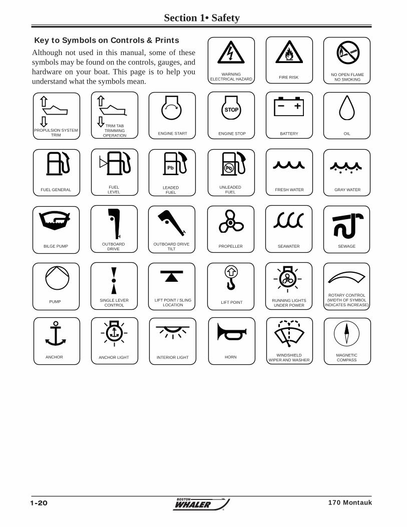
1-20 170 Montauk
Section 1• Safety
R
STOP
Key to Symbols on Controls & PrintsAlthough not used in this manual, some of these symbols may be found on the controls, gauges, and hardware on your boat. This page is to help you understand what the symbols mean.
PROPULSION SYSTEMTRIM
TRIM TABTRIMMING
OPERATION
SINGLE LEVERCONTROL
LIFT POINT / SLING LOCATION
ENGINE START ENGINE STOP
FUEL LEVEL
WARNINGELECTRICAL HAZARD
NO OPEN FLAMENO SMOKINGFIRE RISK
ROTARY CONTROL(WIDTH OF SYMBOL
INDICATES INCREASE)
FRESH WATER GRAY WATERFUEL GENERAL
LIFT POINT
BILGE PUMP PROPELLER
INTERIOR LIGHT
RUNNING LIGHTSUNDER POWER
ANCHOR LIGHT WINDSHIELD WIPER AND WASHER
ANCHOR
BATTERY
HORN
UNLEADEDFUEL
LEADEDFUEL
OUTBOARDDRIVE
OUTBOARD DRIVETILT SEAWATER SEWAGE
PUMP
MAGNETICCOMPASS
OIL
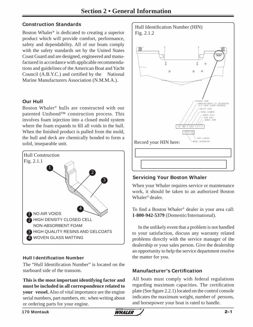
2-1170 Montauk
Section 2 • General Information
R
All boats must comply with federal regulations regarding maximum capacities. The certifi cation plate (See fi gure 2.2.1) located on the control console indicates the maximum weight, number of persons, and horsepower your boat is rated to handle.
Manufacturer’s Certifi cation
Boston Whaler® is dedicated to creating a superior product which will provide comfort, performance, safety and dependability. All of our boats comply with the safety standards set by the United States Coast Guard and are designed, engineered and manu-factured in accordance with applicable recommenda-tions and guidelines of the American Boat and Yacht Council (A.B.Y.C.) and certifi ed by the National Marine Manufacturers Association (N.M.M.A.).
Construction Standards
Our Hull
23
NO AIR VOIDSHIGH DENSITY CLOSED CELLNON-ABSORBENT FOAMHIGH QUALITY RESINS AND GELCOATSWOVEN GLASS MATTING
Boston Whaler® hulls are constructed with our patented Unibond™ construction process. This involves foam injection into a closed mold system where the foam expands to fi ll all voids in the hull. When the fi nished product is pulled from the mold, the hull and deck are chemically bonded to form a solid, inseparable unit.
Hull ConstructionFig. 2.1.1
Hull Identifi cation NumberThe “Hull Identifi cation Number” is located on the starboard side of the transom.
This is the most important identifying factor and must be included in all correspondence related to your vessel. Also of vital importance are the engine serial numbers, part numbers, etc. when writing about or ordering parts for your engine.
Record your HIN here:
Hull Identifi cation Number (HIN)Fig. 2.1.2
When your Whaler requires service or maintenance work, it should be taken to an authorized Boston Whaler® dealer.
To fi nd a Boston Whaler® dealer in your area call: 1-800-942-5379 (Domestic/International).
In the unlikely event that a problem is not handled to your satisfaction, discuss any warranty related problems directly with the service manager of the dealership or your sales person. Give the dealership an opportunity to help the service department resolve the matter for you.
Servicing Your Boston Whaler
1
412
34
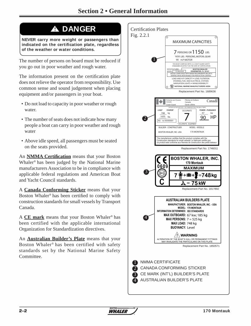
2-2 170 Montauk
Section 2 • General Information
R
7
BOS T ON WHALER, INC . 170 Montauk
75C k W 748 k g
The number of persons on board must be reduced if you go out in poor weather and rough water.
The information present on the certifi cation plate does not relieve the operator from responsibility. Use common sense and sound judgement when placing equipment and/or passengers in your boat.
• Do not load to capacity in poor weather or rough water.
• The number of seats does not indicate how many people a boat can carry in poor weather and rough water
• Above idle speed, all passengers must be seated on the seats provided.
An NMMA Certifi cation means that your Boston Whaler® has been judged by the National Marine manufacturers Association to be in compliance with applicable federal regulations and American Boat and Yacht Council standards.
A Canada Conforming Sticker means that your Boston Whaler® has been certifi ed to comply with construction standards for small vessels by Transport Canada.
A CE mark means that your Boston Whaler® has been certified with the applicable international Organization for Standardization directives.
An Australian Builder’s Plate means that your Boston Whaler® has been certified with safety standards set by the National Marine Safety Committee.
! DANGERNEVER carry more weight or passengers than indicated on the certifi cation plate, regardless of the weather or water conditions.
Certifi cation PlatesFig. 2.2.1
NMMA CERTIFICATECANADA CONFORMING STICKERCE MARK (INT’L) BUILDER’S PLATEAUSTRALIAN BUILDER’S PLATE
123
1
2
3
Replacement Part No. 1689636
Replacement Part No. 1746011
Replacement Part No. 1817892
MAXIMUM CAPACITIES
7 PERSONS OR LBS.1150LBS. PERSONS, MOTOR, GEAR1650
H.P MOTOR90
THIS BOAT COMPLIES WITH U.S. COAST GUARD SAFETYSTANDARDS IN EFFECT ON THE DATE OF CERTIFICATION
MANUFACTURER:MODEL:
BOSTON WHALEREDGEWATER, FL 32141170 Montauk
DESIGN COMPLIANCE WITH NMMA REQUIREMENTS BELOW ISVERIFIED. MFGR. RESPONSIBLE FOR PRODUCTION CONTROL.
LOAD AND H.P CAPACITY LEVEL FLOTATIONSTEERING, FUEL AND ELECTRICAL SYSTEMSNAVIGATION LIGHTS MANEUVERABILITY
NATIONAL MARINE MANUFACTURERS ASSN.
CanadaRATINGS IN FAIR WEATHER - RECOMMENDATIONS PAR BEAU TEMPS
748
1650 767
90
170 MONTAUK
Fisheries and OceansCanada
Coast Guard
Peches et OceansCanadaGarde cotiere
LOAD* CHARGE* POWER - PUISSANCE
lbs.
kg kw
HPNO. -no XXXX00001
OCCUPANTS
* OCCUPANTS, EQUIPMENT
BUILDER - CONSTRUCTUER MODEL - MODELE
BOSTON WHALER, INC -USA
The manufacturer certifies that this product complies with theConstruction standards for small vessels/ Le fabricant certifie quece produit este conforme aux Normes de construction des petits bateaux
AUSTRALIAN BUILDERS PLATE MANUFACTURER:
MODEL:INFORMATION DETERMINED:
MAX OUTBOARD:MAX PERSONS:
MAX LOAD:BUOYANCY:
BOSTON WHALER, INC. - USA170 MONTAUKISO STANDARDS
748 kg7 = 525 kg
! WARNING ALTERATION OF THE BOAT’S HULL OR PERMANENT FITTINGS
MAY INVALIDATE THE PARTICULARS ON THIS PLATE
67 kw; 185 kg
Level
Replacement Part No. 1850571
4
4
2-3170 Montauk
Section 2 • General Information
R
Power Capacity
Always adjust the speed and direction of the craft to the varying sea conditions.
NOTICE
• DO NOT Exceed the maximum engine power rating stated on the certifi cation plate.
• Use caution while accelerating. Make sure passengers are safely seated in designated areas of the boat and all gear is stowed securely.
! WARNING
CE Certifi cation Design Category
A (Ocean): Designed for extended voyages where conditions may exceed wind force 8 on the Beaufort scale (47 mph and above) and signifi cant wave heights of 4 meters (13.12 feet) and above, and vessels largely self-suffi cient.
B (Offshore): Designed for offshore voyages where conditions up to, and including, wind force 8 (39-46 mph) and signifi cant wave heights up to, and including 4 meters (13.12 feet) may be experienced.
C (Inshore): Designed for voyages in coastal waters, large bays, estuaries, lakes and rivers where conditions up to, and including, wind force 6 (25-31 mph) and signifi cant wave heights up to, andincluding, 2 meters (6 .56 fee t ) may be experienced.
D (Sheltered waters): Designed for voyages on small lakes, rivers and canals where conditions up to, and including, wind force 4 (13-18 mph) and signifi cant wave heights up to, and including, 0.5 meters (1.64 feet) may be experienced.
Your 170 Montauk is design category C
The signifi cant wave height is considered to be the primary factor for determining design category. Other parameters (e.g. meteorological) are descriptions of when these wave heights may be expected to occur. Refer to page 1-12 for weather information.
The certifi cation plate, as well as “Specifi cations & Dimensions” on the following page has the maximum rated power listed for your boat. DO NOT EXCEED THIS RATING. The various engine types offered today are more powerful and require constant maintenance to stay at optimal performance. It is required of the owner/operator to read all information regarding safety features, warning notices and maintenance schedules for continued safe operation of the engine.
The engine on the 170 Montauk has been tested and proven to be best suited for general use under normal conditions and load.
If you are re-powering your Boston Whaler®, you should pay particular attention to the maximum/minimum horsepower and maximum safe engine weight load your Boston Whaler® boat is rated for.
The 170 Montauk is designed for a maximum outboard engine weight of 410 LBS (185 kg).
It is imperat ive that you fol low the recommendations listed on your capacity plate regarding the maximum amount of weight the boat can safely carry.
! WARNING
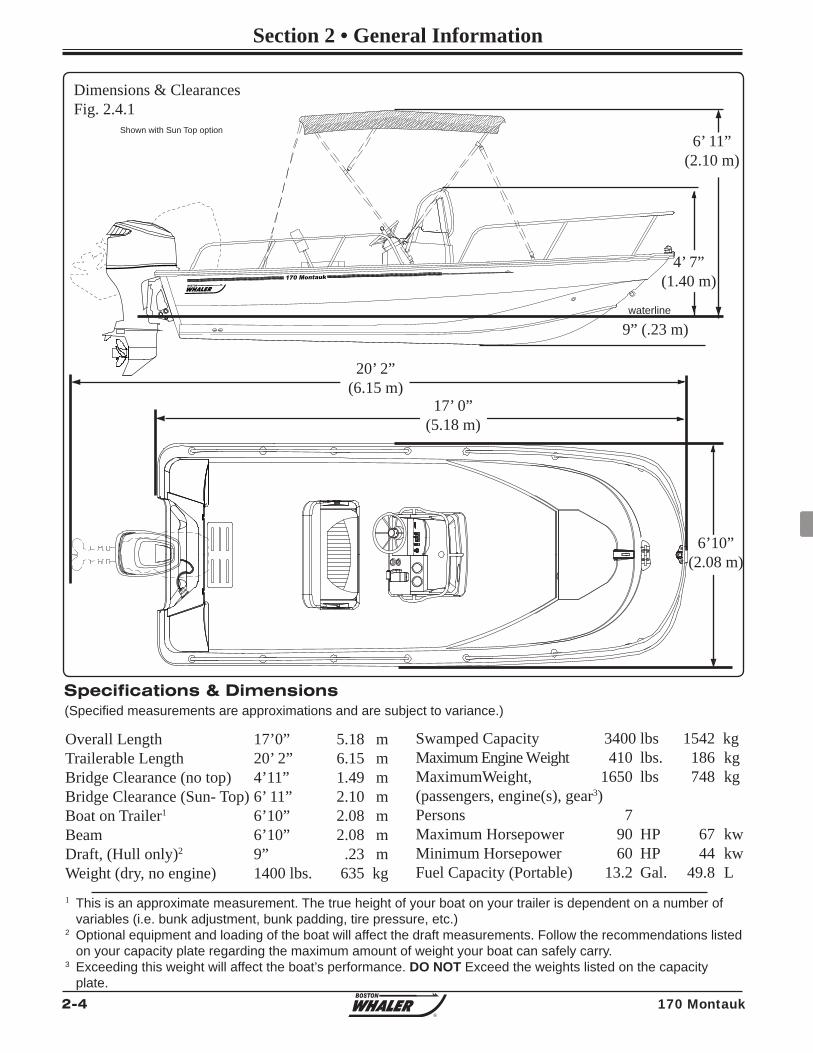
2-4 170 Montauk
Section 2 • General Information
R
170 Montauk
Overall Length 17’0” 5.18 mTrailerable Length 20’ 2” 6.15 mBridge Clearance (no top) 4’11” 1.49 mBridge Clearance (Sun- Top) 6’ 11” 2.10 mBoat on Trailer1 6’10” 2.08 mBeam 6’10” 2.08 mDraft, (Hull only)2 9” .23 mWeight (dry, no engine) 1400 lbs. 635 kg
Specifications & Dimensions(Specifi ed measurements are approximations and are subject to variance.)
1 This is an approximate measurement. The true height of your boat on your trailer is dependent on a number of variables (i.e. bunk adjustment, bunk padding, tire pressure, etc.)2 Optional equipment and loading of the boat will affect the draft measurements. Follow the recommendations listed on your capacity plate regarding the maximum amount of weight your boat can safely carry.3 Exceeding this weight will affect the boat’s performance. DO NOT Exceed the weights listed on the capacity plate.
Dimensions & ClearancesFig. 2.4.1
20’ 2”(6.15 m)
6’10”(2.08 m)
9” (.23 m)
Swamped Capacity 3400 lbs 1542 kgMaximum Engine Weight 410 lbs. 186 kgMaximumWeight, 1650 lbs 748 kg(passengers, engine(s), gear3) Persons 7 Maximum Horsepower 90 HP 67 kwMinimum Horsepower 60 HP 44 kwFuel Capacity (Portable) 13.2 Gal. 49.8 L
Shown with Sun Top option
4’ 7”(1.40 m)
6’ 11”(2.10 m)
17’ 0”(5.18 m)
waterline
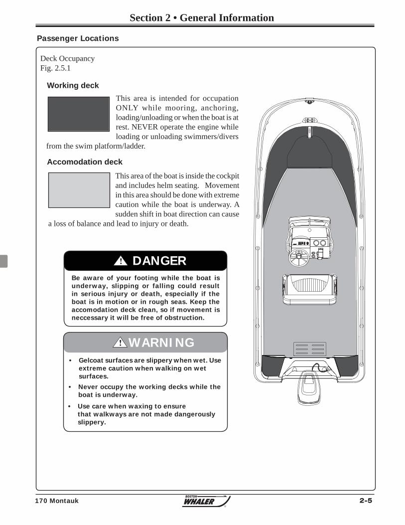
2-5170 Montauk
Section 2 • General Information
R
This area is intended for occupation ONLY while mooring, anchoring, loading/unloading or when the boat is at rest. NEVER operate the engine while loading or unloading swimmers/divers
from the swim platform/ladder.
This area of the boat is inside the cockpit and includes helm seating. Movement in this area should be done with extreme caution while the boat is underway. A sudden shift in boat direction can cause
a loss of balance and lead to injury or death.
Deck OccupancyFig. 2.5.1
Be aware of your footing while the boat is underway, slipping or falling could result in serious injury or death, especially if the boat is in motion or in rough seas. Keep the accomodation deck clean, so if movement is neccessary it will be free of obstruction.
! DANGER
Passenger Locations
• Gelcoat surfaces are slippery when wet. Use extreme caution when walking on wet surfaces.
• Never occupy the working decks while the boat is underway.
! WARNING
• Use care when waxing to ensure that walkways are not made dangerously slippery.
Working deck
Accomodation deck
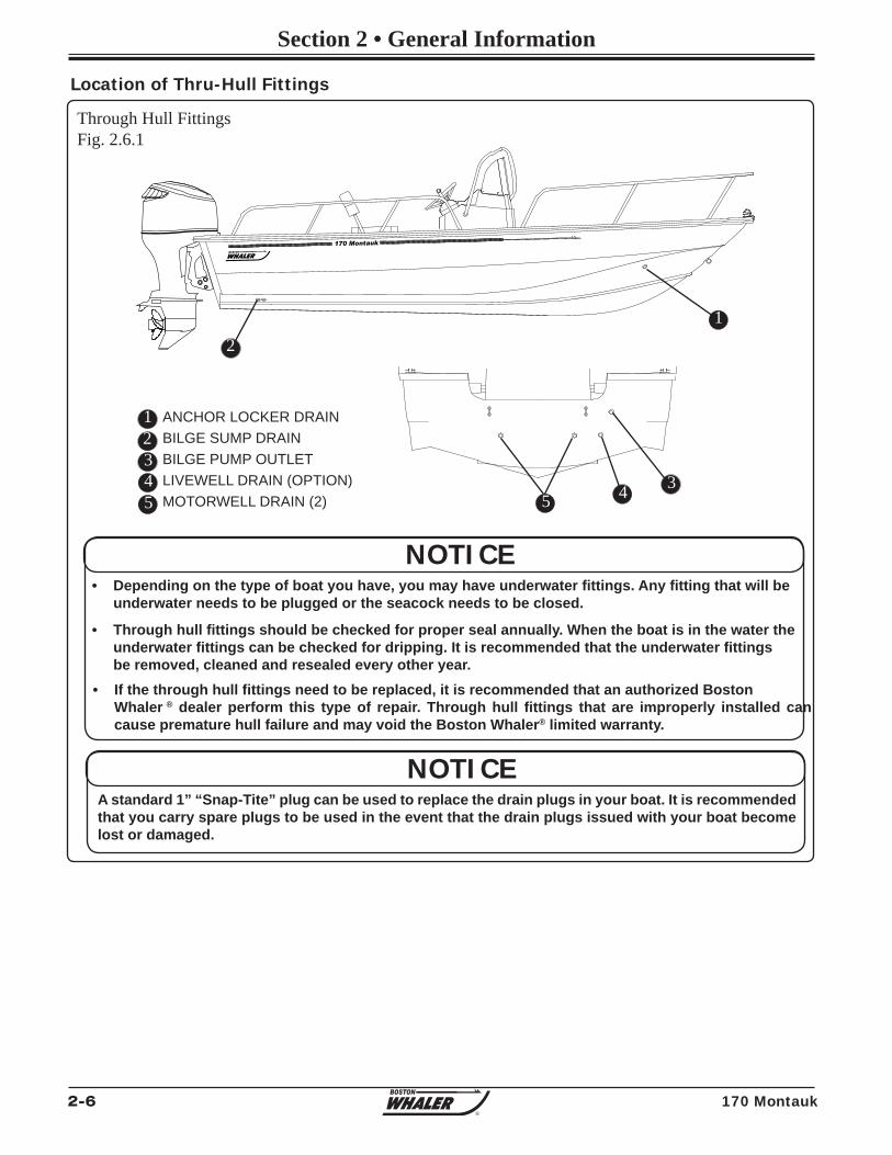
2-6 170 Montauk
Section 2 • General Information
R
170 Montauk
Through Hull FittingsFig. 2.6.1
123
ANCHOR LOCKER DRAINBILGE SUMP DRAINBILGE PUMP OUTLETLIVEWELL DRAIN (OPTION)MOTORWELL DRAIN (2)
Location of Thru-Hull Fittings
NOTICE• Depending on the type of boat you have, you may have underwater fi ttings. Any fi tting that will be underwater needs to be plugged or the seacock needs to be closed.
• Through hull fi ttings should be checked for proper seal annually. When the boat is in the water the underwater fi ttings can be checked for dripping. It is recommended that the underwater fi ttings be removed, cleaned and resealed every other year.• If the through hull fi ttings need to be replaced, it is recommended that an authorized Boston Whaler ® dealer perform this type of repair. Through hull fi ttings that are improperly installed can cause premature hull failure and may void the Boston Whaler® limited warranty.
4
12
35
NOTICEA standard 1” “Snap-Tite” plug can be used to replace the drain plugs in your boat. It is recommended that you carry spare plugs to be used in the event that the drain plugs issued with your boat become lost or damaged.
45
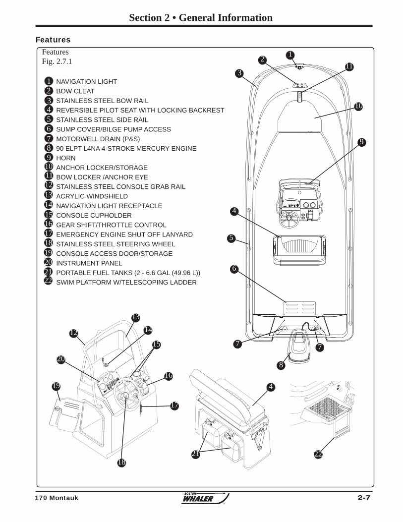
2-7170 Montauk
Section 2 • General Information
R
NAVIGATION LIGHTBOW CLEATSTAINLESS STEEL BOW RAIL REVERSIBLE PILOT SEAT WITH LOCKING BACKREST STAINLESS STEEL SIDE RAILSUMP COVER/BILGE PUMP ACCESSMOTORWELL DRAIN (P&S)90 ELPT L4NA 4-STROKE MERCURY ENGINEHORNANCHOR LOCKER/STORAGEBOW LOCKER /ANCHOR EYESTAINLESS STEEL CONSOLE GRAB RAILACRYLIC WINDSHIELDNAVIGATION LIGHT RECEPTACLECONSOLE CUPHOLDERGEAR SHIFT/THROTTLE CONTROLEMERGENCY ENGINE SHUT OFF LANYARDSTAINLESS STEEL STEERING WHEELCONSOLE ACCESS DOOR/STORAGEINSTRUMENT PANELPORTABLE FUEL TANKS (2 - 6.6 GAL (49.96 L))SWIM PLATFORM W/TELESCOPING LADDER
123456789
101112
FeaturesFig. 2.7.1
Features
131415161718192021
12
3
4
5
6
7
8
9
10
11
12
1314
15
16
17
18
19
20
21
7
4
22
22
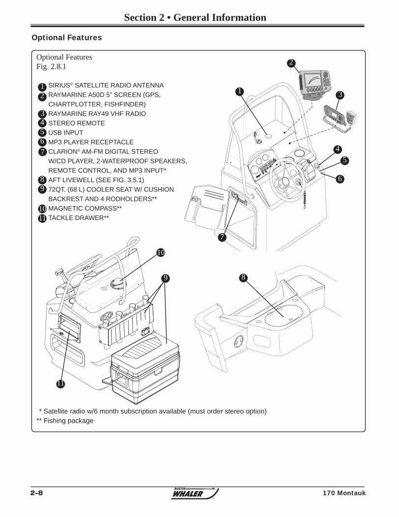
2-8 170 Montauk
Section 2 • General Information
R
12
ACTIVEPAGE/MENU
CANCEL
WPTSMOB
RANGE
OUT
IN
OK
Optional FeaturesFig. 2.8.1
SIRIUS® SATELLITE RADIO ANTENNARAYMARINE A50D 5” SCREEN (GPS, CHARTPLOTTER, FISHFINDER)RAYMARINE RAY49 VHF RADIOSTEREO REMOTEUSB INPUTMP3 PLAYER RECEPTACLECLARION® AM-FM DIGITAL STEREOW/CD PLAYER, 2-WATERPROOF SPEAKERS, REMOTE CONTROL, AND MP3 INPUT*AFT LIVEWELL (SEE FIG. 3.5.1)72QT. (68 L) COOLER SEAT W/ CUSHION BACKREST AND 4 RODHOLDERS**MAGNETIC COMPASS**TACKLE DRAWER**
Optional Features
12
34567
89
1110
1
2
3
45
9
** Fishing package
7
8
11
6
10
* Satellite radio w/6 month subscription available (must order stereo option)
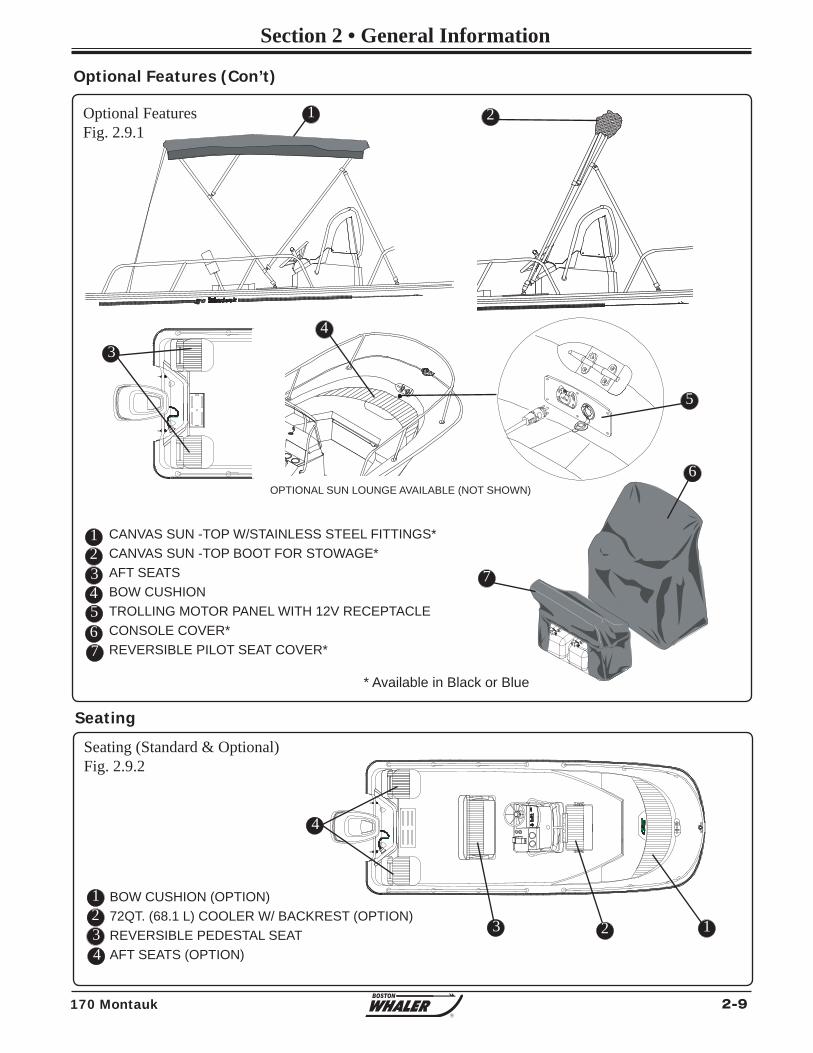
2-9170 Montauk
Section 2 • General Information
R
Seating (Standard & Optional)Fig. 2.9.2
Seating
BOW CUSHION (OPTION)72QT. (68.1 L) COOLER W/ BACKREST (OPTION)REVERSIBLE PEDESTAL SEATAFT SEATS (OPTION)
123
* Available in Black or Blue
Optional Features (Con’t)
12345
CANVAS SUN -TOP W/STAINLESS STEEL FITTINGS*CANVAS SUN -TOP BOOT FOR STOWAGE*AFT SEATSBOW CUSHIONTROLLING MOTOR PANEL WITH 12V RECEPTACLECONSOLE COVER*REVERSIBLE PILOT SEAT COVER*
1 2
34
7
6
123
4
4
Optional FeaturesFig. 2.9.1
6
5
7
OPTIONAL SUN LOUNGE AVAILABLE (NOT SHOWN)
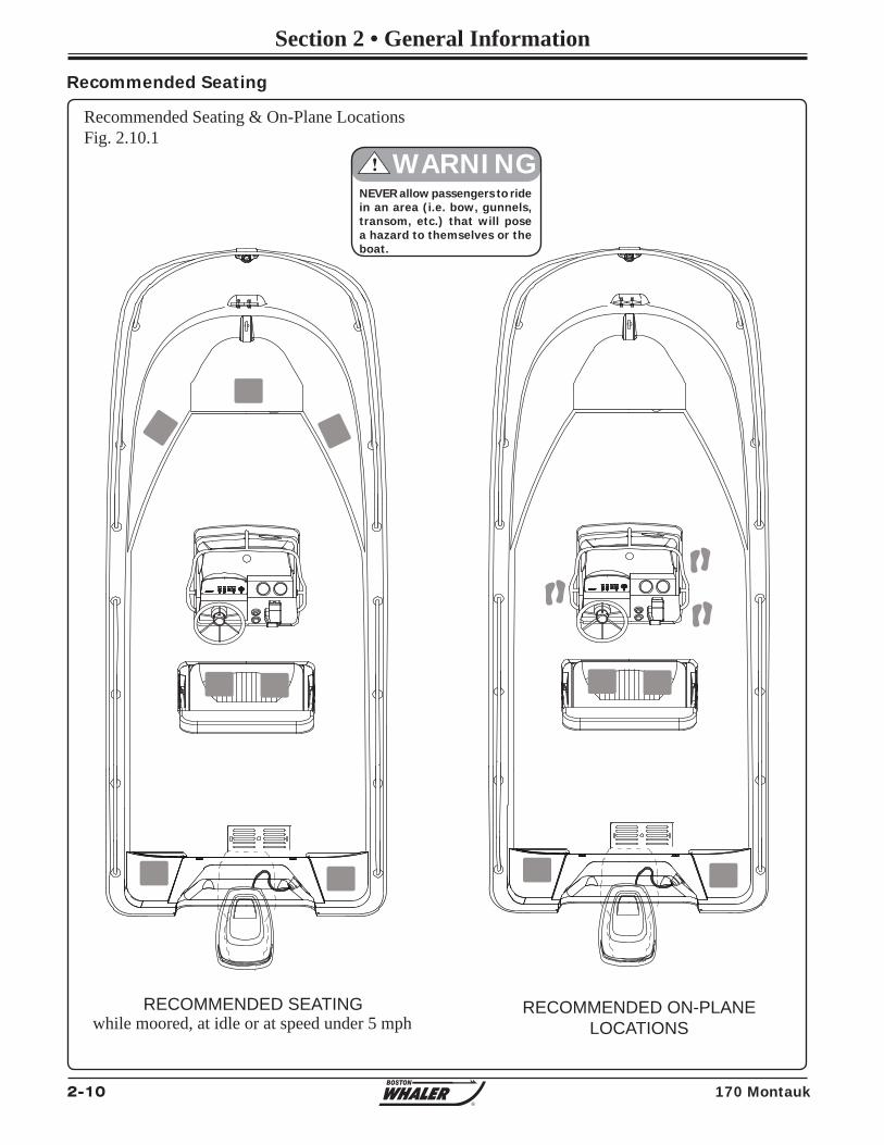
2-10 170 Montauk
Section 2 • General Information
R
Recommended Seating & On-Plane LocationsFig. 2.10.1
Recommended Seating
RECOMMENDED SEATINGwhile moored, at idle or at speed under 5 mph
RECOMMENDED ON-PLANELOCATIONS
NEVER allow passengers to ride in an area (i.e. bow, gunnels, transom, etc.) that will pose a hazard to themselves or the boat.
! WARNING
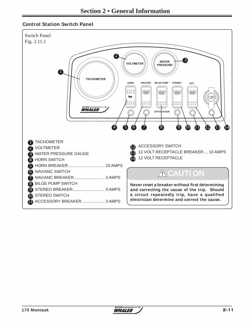
2-11170 Montauk
Section 2 • General Information
R
Switch PanelFig. 2.11.1
TACHOMETERVOLTMETERWATER PRESSURE GAUGEHORN SWITCHHORN BREAKER ................................ 10 AMPSNAV/ANC SWITCHNAV/ANC BREAKER ........................... 3 AMPSBILGE PUMP SWITCHSTEREO BREAKER............................ 3 AMPSSTEREO SWITCHACCESSORY BREAKER .................... 3 AMPS
Control Station Switch Panel
123456789
1011
121314
12V
TACHOMETERNAV/ANC BILGE PUMP ACCSTEREOHORN
WATERPRESSUREVOLTMETER
R OFF/AUTO/ON
1
23
4 5 6 7 8 9 10 11 12 13 14
ACCESSORY SWITCH12 VOLT RECEPTACLE BREAKER.... 10 AMPS12 VOLT RECEPTACLE
! CAUTIONNever reset a breaker without fi rst determining and correcting the cause of the trip. Should a circuit repeatedly trip, have a qualified electrician determine and correct the cause.
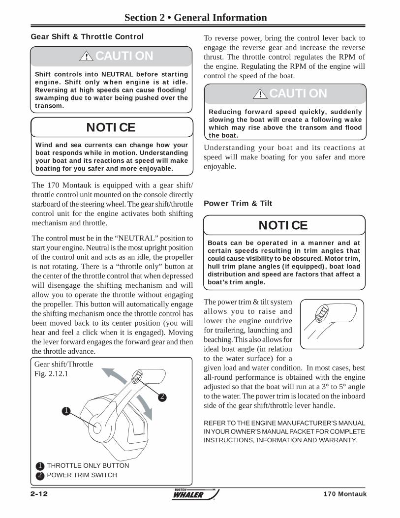
2-12 170 Montauk
Section 2 • General Information
R
To reverse power, bring the control lever back to engage the reverse gear and increase the reverse thrust. The throttle control regulates the RPM of the engine. Regulating the RPM of the engine will control the speed of the boat.
Understanding your boat and its reactions at speed will make boating for you safer and more enjoyable.
Power Trim & Tilt
The power trim & tilt system allows you to raise and lower the engine outdrive for trailering, launching and beaching. This also allows for ideal boat angle (in relation to the water surface) for a given load and water condition. In most cases, best all-round performance is obtained with the engine adjusted so that the boat will run at a 3° to 5° angle to the water. The power trim is located on the inboard side of the gear shift/throttle lever handle.
Shift controls into NEUTRAL before starting engine. Shift only when engine is at idle. Reversing at high speeds can cause fl ooding/swamping due to water being pushed over the transom.
! CAUTION
Wind and sea currents can change how your boat responds while in motion. Understanding your boat and its reactions at speed will make boating for you safer and more enjoyable.
NOTICE
Gear Shift & Throttle Control
The 170 Montauk is equipped with a gear shift/throttle control unit mounted on the console directly starboard of the steering wheel. The gear shift/throttle control unit for the engine activates both shifting mechanism and throttle.
The control must be in the “NEUTRAL” position to start your engine. Neutral is the most upright position of the control unit and acts as an idle, the propeller is not rotating. There is a “throttle only” button at the center of the throttle control that when depressed will disengage the shifting mechanism and will allow you to operate the throttle without engaging the propeller. This button will automatically engage the shifting mechanism once the throttle control has been moved back to its center position (you will hear and feel a click when it is engaged). Moving the lever forward engages the forward gear and then the throttle advance.
Reducing forward speed quickly, suddenly slowing the boat will create a following wake which may rise above the transom and fl ood the boat.
! CAUTION
Gear shift/ThrottleFig. 2.12.1
DNUP
THROTTLE ONLY BUTTONPOWER TRIM SWITCH
12
1
2
DN
UP
Boats can be operated in a manner and at certain speeds resulting in trim angles that could cause visibility to be obscured. Motor trim, hull trim plane angles (if equipped), boat load distribution and speed are factors that affect a boat’s trim angle.
NOTICE
REFER TO THE ENGINE MANUFACTURER’S MANUAL IN YOUR OWNER’S MANUAL PACKET FOR COMPLETE INSTRUCTIONS, INFORMATION AND WARRANTY.
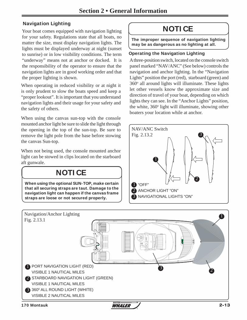
2-13170 Montauk
Section 2 • General Information
R
When operating in reduced visibility or at night it is only prudent to slow the boats speed and keep a “proper lookout”. It is important that you understand navigation lights and their usage for your safety and the safety of others.
When using the canvas sun-top with the console mounted anchor light be sure to slide the light through the opening in the top of the sun-top. Be sure to remove the light pole from the base before stowing the canvas Sun-top.
When not being used, the console mounted anchor light can be stowed in clips located on the starboard aft gunwale.
Navigation/Anchor LightingFig. 2.13.1
A three-position switch, located on the console switch panel marked “NAV/ANC” (See below) controls the navigation and anchor lighting. In the “Navigation Lights” position the port (red), starboard (green) and 360o all around lights will illuminate. These lights let other vessels know the approximate size and direction of travel of your boat, depending on which lights they can see. In the “Anchor Lights” position, the white, 360o light will illuminate, showing other boaters your location while at anchor.
Navigation LightingYour boat comes equipped with navigation lighting for your safety. Regulations state that all boats, no matter the size, must display navigation lights. The lights must be displayed underway at night (sunset to sunrise) or in low visibility conditions. The term “underway” means not at anchor or docked. It is the responsibility of the operator to ensure that the navigation lights are in good working order and that the proper lighting is shown.
Operating the Navigation Lighting
The improper sequence of navigation lighting may be as dangerous as no lighting at all.
NOTICE
1
2
3
PORT NAVIGATION LIGHT (RED)VISIBLE 1 NAUTICAL MILESSTARBOARD NAVIGATION LIGHT (GREEN)VISIBLE 1 NAUTICAL MILES3600 ALL ROUND LIGHT (WHITE)VISIBLE 2 NAUTICAL MILES
NAV/ANC SwitchFig. 2.13.2
123
“OFF”ANCHOR LIGHT “ON”NAVIGATIONAL LIGHTS “ON”
1
2
3
When using the optional SUN-TOP, make certain that all securing straps are taut. Damage to the navigation light can happen if the canvas frame straps are loose or not secured properly.
NOTICE
1
23
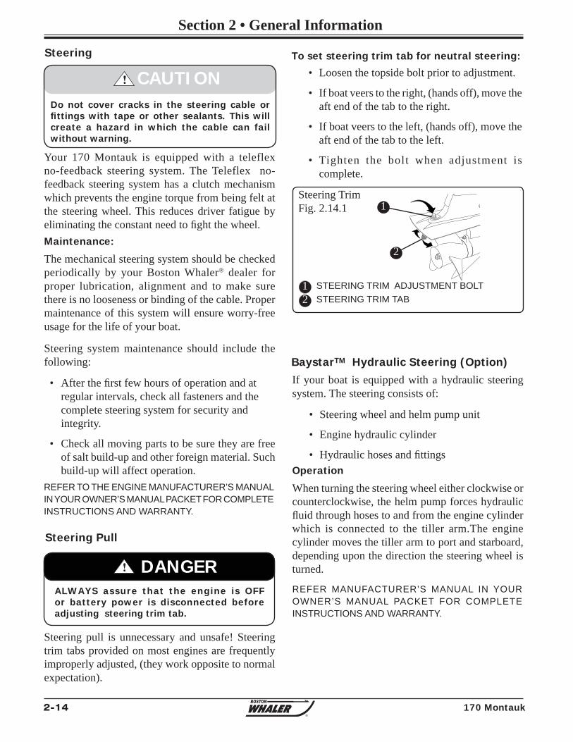
2-14 170 Montauk
Section 2 • General Information
R
Your 170 Montauk is equipped with a teleflex no-feedback steering system. The Teleflex no-feedback steering system has a clutch mechanism which prevents the engine torque from being felt at the steering wheel. This reduces driver fatigue by eliminating the constant need to fi ght the wheel.Maintenance:
The mechanical steering system should be checked periodically by your Boston Whaler® dealer for proper lubrication, alignment and to make sure there is no looseness or binding of the cable. Proper maintenance of this system will ensure worry-free usage for the life of your boat.
Steering system maintenance should include the following:
• After the fi rst few hours of operation and at regular intervals, check all fasteners and the complete steering system for security and integrity.
• Check all moving parts to be sure they are free of salt build-up and other foreign material. Such build-up will affect operation.
Steering
Steering pull is unnecessary and unsafe! Steering trim tabs provided on most engines are frequently improperly adjusted, (they work opposite to normal expectation).
Steering Pull
Do not cover cracks in the steering cable or fi ttings with tape or other sealants. This will create a hazard in which the cable can fail without warning.
! CAUTION
Steering TrimFig. 2.14.1
STEERING TRIM ADJUSTMENT BOLTSTEERING TRIM TAB
REFER TO THE ENGINE MANUFACTURER’S MANUAL IN YOUR OWNER’S MANUAL PACKET FOR COMPLETE INSTRUCTIONS AND WARRANTY.
12
1
2
To set steering trim tab for neutral steering:
• Loosen the topside bolt prior to adjustment.
• If boat veers to the right, (hands off), move the aft end of the tab to the right.
• If boat veers to the left, (hands off), move the aft end of the tab to the left.
• Tighten the bolt when adjustment is complete.
ALWAYS assure that the engine is OFF or battery power is disconnected before adjusting steering trim tab.
! DANGER
If your boat is equipped with a hydraulic steering system. The steering consists of:
• Steering wheel and helm pump unit
• Engine hydraulic cylinder
• Hydraulic hoses and fi ttingsOperation
When turning the steering wheel either clockwise or counterclockwise, the helm pump forces hydraulic fl uid through hoses to and from the engine cylinder which is connected to the tiller arm.The engine cylinder moves the tiller arm to port and starboard, depending upon the direction the steering wheel is turned.
BaystarTM Hydraulic Steering (Option)
REFER MANUFACTURER’S MANUAL IN YOUR OWNER’S MANUAL PACKET FOR COMPLETE INSTRUCTIONS AND WARRANTY.
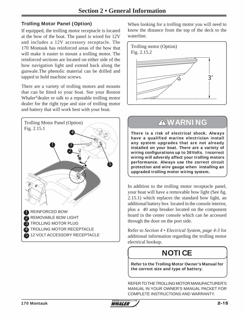
2-15170 Montauk
Section 2 • General Information
R
When looking for a trolling motor you will need to know the distance from the top of the deck to the waterline.
In addition to the trolling motor receptacle panel, your boat will have a removable bow light (See fi g. 2.15.1) which replaces the standard bow light, an additional battery box located in the console interior, plus a 40 amp breaker located on the component board in the center console which can be accessed through the door on the port side.
Refer to Section 4 • Electrical System, page 4-3 for additional information regarding the trolling motor electrical hookup.
If equipped, the trolling motor receptacle is located at the bow of the boat. The panel is wired for 12V and includes a 12V accessory receptacle. The 170 Montauk has reinforced areas of the bow that will make it easier to mount a trolling motor. The reinforced sections are located on either side of the bow navigation light and extend back along the gunwale.The phenolic material can be drilled and tapped to hold machine screws.
There are a variety of trolling motors and mounts that can be fi tted to your boat. See your Boston Whaler®dealer or talk to a reputable trolling motor dealer for the right type and size of trolling motor and battery that will work best with your boat.
There is a risk of electrical shock. Always have a qualified marine electrician install any system upgrades that are not already installed on your boat. There are a variety of wiring confi gurations up to 36Volts. Incorrect wiring will adversly affect your trolling motors performance. Always use the correct circuit protection and wire gauge when installing an upgraded trolling motor wiring system.
! WARNING
Trolling motor (Option)Fig. 2.15.2
REFER TO THE TROLLING MOTOR MANUFACTURER’S MANUAL IN YOUR OWNER’S MANUAL PACKET FOR COMPLETE INSTRUCTIONS AND WARRANTY.
NOTICERefer to the Trolling Motor Owner’s Manual for the correct size and type of battery.
3‘
Trolling Motor Panel (Option)
123
REINFORCED BOWREMOVABLE BOW LIGHTTROLLING MOTOR PLUGTROLLING MOTOR RECEPTACLE12 VOLT ACCESSORY RECEPTACLE
4
1 3
4
5
5
2
Trolling Motor Panel (Option)Fig. 2.15.1
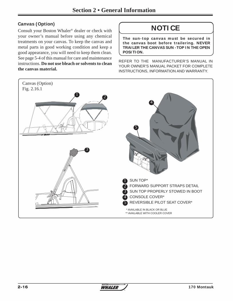
2-16 170 Montauk
Section 2 • General Information
R
Canvas (Option) Consult your Boston Whaler® dealer or check with your owner’s manual before using any chemical treatments on your canvas. To keep the canvas and metal parts in good working condition and keep a good appearance, you will need to keep them clean. See page 5-4 of this manual for care and maintenance instructions. Do not use bleach or solvents to clean the canvas material.
Canvas (Option)Fig. 2.16.1
1234
SUN TOP* FORWARD SUPPORT STRAPS DETAILSUN TOP PROPERLY STOWED IN BOOTCONSOLE COVER* REVERSIBLE PILOT SEAT COVER*
1 2
3
4
5
The sun-top canvas must be secured in the canvas boot before trailering. NEVER TRAILER THE CANVAS SUN -TOP IN THE OPEN POSITION.
NOTICE
** AVAILABLE WITH COOLER COVER
REFER TO THE MANUFACTURER’S MANUAL IN YOUR OWNER’S MANUAL PACKET FOR COMPLETE INSTRUCTIONS, INFORMATION AND WARRANTY.
* AVAILABLE IN BLACK OR BLUE
5
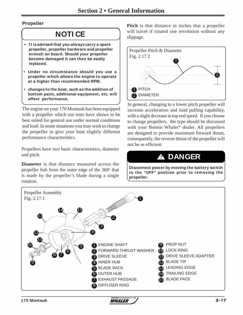
2-17170 Montauk
Section 2 • General Information
R
Propeller
• It is advised that you always carry a spare propeller, propeller hardware and propeller wrench on board. Should your propeller become damaged it can then be easily replaced.
• Under no circumstance should you use a propeller which allows the engine to operate at a higher than recommended RPM.
NOTICE
The engine on your 170 Montauk has been equipped with a propeller which our tests have shown to be best suited for general use under normal conditions and load. In some situations you may wish to change the propeller to give your boat slightly different performance characteristics.
! DANGERDisconnect power by moving the battery switch to the “OFF” position prior to removing the propeller.
Propellers have two basic characteristics, diameter and pitch.
Diameter is that distance measured across the propeller hub from the outer edge of the 360o that is made by the propeller’s blade during a single rotation.
Propeller Pitch & DiameterFig. 2.17.2
PITCHDIAMETER
12
1
2
Propeller AssemblyFig. 2.17.1
12345678
ENGINE SHAFTFORWARD THRUST WASHERDRIVE SLEEVEINNER HUBBLADE BACKOUTER HUBEXHAUST PASSAGEDIFFUSER RING
In general, changing to a lower pitch propeller will increase acceleration and load pulling capability, with a slight decrease in top end speed. If you choose to change propellers, the type should be discussed with your Boston Whaler® dealer. All propellers are designed to provide maximum forward thrust, consequently, the reverse thrust of the propeller will not be as effi cient.
Pitch is that distance in inches that a propeller will travel if rotated one revolution without any slippage.
1112131415
PROP NUTLOCK RINGDRIVE SLEEVE ADAPTERBLADE TIPLEADING EDGETRAILING EDGEBLADE FACE
• changes to the boat, such as the addition of bottom paint, additional equipment, etc. will affect performance.
1
2
34
5678
910
1112
1314 15
9
10
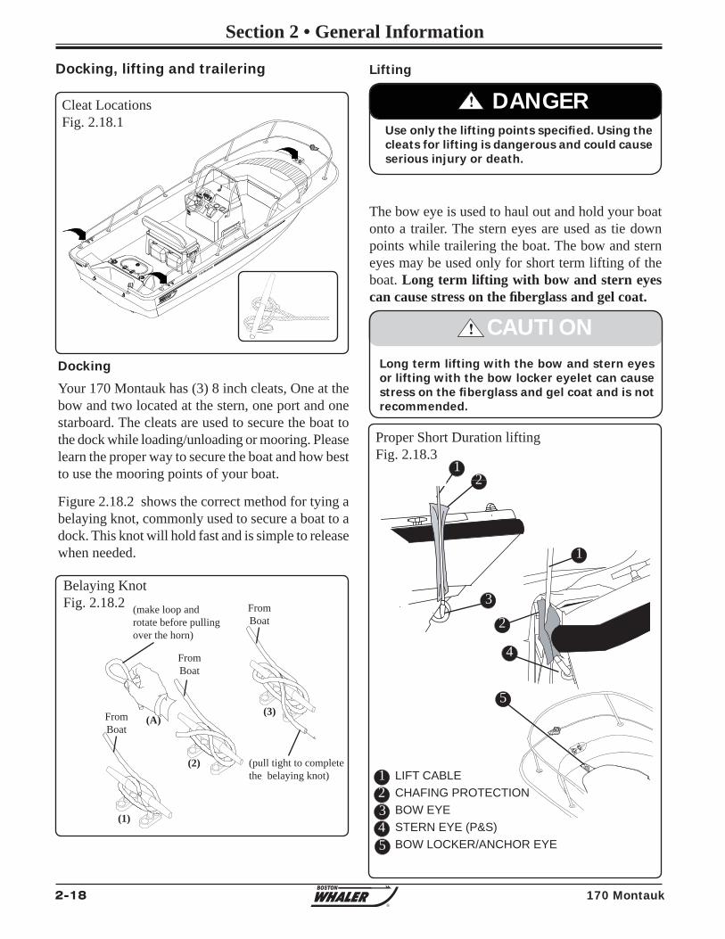
2-18 170 Montauk
Section 2 • General Information
R
170 Montauk
Docking
Your 170 Montauk has (3) 8 inch cleats, One at the bow and two located at the stern, one port and one starboard. The cleats are used to secure the boat to the dock while loading/unloading or mooring. Please learn the proper way to secure the boat and how best to use the mooring points of your boat.
Figure 2.18.2 shows the correct method for tying a belaying knot, commonly used to secure a boat to a dock. This knot will hold fast and is simple to release when needed.
Docking, lifting and trailering
Cleat LocationsFig. 2.18.1
FromBoat
FromBoat
FromBoat
(make loop and rotate before pulling over the horn)
(pull tight to completethe belaying knot)
(1)
(2)
(3)(A)
Belaying KnotFig. 2.18.2
Lifting
The bow eye is used to haul out and hold your boat onto a trailer. The stern eyes are used as tie down points while trailering the boat. The bow and stern eyes may be used only for short term lifting of the boat. Long term lifting with bow and stern eyes can cause stress on the fi berglass and gel coat.
! DANGERUse only the lifting points specifi ed. Using the cleats for lifting is dangerous and could cause serious injury or death.
1234
LIFT CABLECHAFING PROTECTIONBOW EYESTERN EYE (P&S)BOW LOCKER/ANCHOR EYE
12
3
1
2
4
! CAUTIONLong term lifting with the bow and stern eyes or lifting with the bow locker eyelet can cause stress on the fi berglass and gel coat and is not recommended.
5
5
Proper Short Duration liftingFig. 2.18.3
2-19170 Montauk
Section 2 • General Information
R
Tie-Down Straps - Can be used to secure the boat from the stern. The tie-down straps hook into the tie-down loops on the trailer frame and to the stern eyes on the transom. Padding (or similar) chafe protection should be used wherever the tie-down straps come in contact with the hull.
Safety Chains - Safety chains are also important; the chains are connected to the trailer and should be of suffi cient length to reach the frame of the tow vehicle and should be long enough to allow the tow vehicle to turn without binding or tensioning . Attach the chains by crisscrossing them under the tongue of the trailer and then attaching them to the tow vehicle.
Trailer Hitch - A properly matched trailer hitch ball and coupler is important. Make certain that the coupler and the hitch ball are properly seated and locked.
The trailer features a unique “swing tongue” (See fi gure 2.20.1). Be sure that the pin is in place and the hairpin cotter is inserted to prevent the pin from backing out while pulling the trailer.
Securing the Trailer to the Tow Vehicle
Your warranty may be void if you use a trailer with rollers. Use a trailer with bunks ONLY
NOTICE
Safety Chain - There is a safety chain that attaches to the bow eye and will keep the boat from sliding off the trailer in the event that the winch strap or cable breaks. Hook this up fi rst.
Trailer SafetySecuring the Boat to the Trailer
TraileringThe 170 Montauk is equipped with a galvanized trailer which is best suited for length and width of the boat. If you have a trailer or plan on purchasing a trailer separately, there are some points you need to consider, such as:
• Having a center roller and keel guards will help provide good support for the keel, also provide good fore and aft support.
Whether you are lifting your boat out of the water for routine maintenance or long term storage, consider the following:
• If you are using a professional lifting service, it is prudent to check all credentials and ask for proof of insurance to protect your investment.
• Use a wide, fl at, belting sling for lifting ,to minimize stress on the gunwales. Careful location of the sling is required. DO NOT PLACE SLINGS WHERE UNDER WATER FITTINGS WILL BE IN CONTACT.
• If using a lifting hook, attach to bow eye and the stern lifting eyes mounted on the transom. Always use a spreader bar on the stern eyes and use chafi ng protection on the top of the transom.
• All drain plugs (i.e. transom, fi shwell, deck, etc.) should be pulled out and the boat positioned with the bow slightly higher than the stern so that any water which is allowed to accumulate in the cockpit and/or bilge can easily drain from the boat.
Tie-down straps should never be used by themselves, they are only used to help in keeping the boat secured to the trailer. Make certain that the safety chain is properly secured to the bow eye.
! DANGER
For long term lifting or storage, use flat, wide belt-type slings and spreaders long enough to keep pressure from gunwales. DO NOT place slings where they may lift on underwater fi ttings.
• Trailers equipped with rollers instead of bunks can damage the foam sandwich hull of your boat and should never be used.
• Bunks provide a more even weight distribution.
2-20 170 Montauk
Section 2 • General Information
R
If equipped, the optional disc brakes on your trailer are designed to energize automatically when the tow vehicle’s brakes are applied. As the tow vehicle slows or stops, the forward momentum of the trailer against the hitch ball creates hydraulic pressure inside the brake actuator. The hydraulic pressure presses the brake calipers against the rotors, effectively slowing and ultimately stopping the rotation of the wheels.
The advantages offered by disc brakes over drum style brakes include:
• Improved resistance to fade on downhill grades.
• Self adjusting.
• Maintain braking effi ciency throughout wear.
• Recover quickly after being submerged.
• Less susceptible to corrosion.
• Require less maintenance.
Disc Brakes (Option)
Check your brake system before each trip.
NOTICE
Operation, Care and Maintenance
Read and understand the instructions in your trailer owner’s manual regarding towing capability, hitch requirements, and other towing considerations.
A light surface rust on the rotors is normal if the trailer has not been used in a week or so. The brake pads will wipe the rotors clean in the fi rst few miles of travel.
However, if the trailer has been idle for an extended period of time or has been frequently submerged in saltwater without being fl ushed out, severe corrosion can occur. A heavy coating of rust must be cleaned or the components replaced before towing to ensure safe braking.
Check for rust damage annually. More frequently if used in very humid environmens, or in saltwater.
REFER TO THE MANUFACTURER’S MANUAL IN YOUR OWNER’S MANUAL PACKET FOR COMPLETE INSTRUCTIONS, INFORMATION AND WARRANTY.
If you have been in saltwater, the single most important maintenance step for disc (or drum) brakes is to fl ush them thoroughly with fresh water.
NOTICE
! CAUTIONDO NOT rely on the power trim/tilt system or tilt support lever on your outboard to maintain proper ground clearance for trailering. THE OUTBOARD TILT SUPPORT LEVER IS NOT INTENDED TO SUPPORT THE OUTBOARD FOR TRAILERING
Trailering the Engine
It is best to trailer your boat with the outboard tilted down in a vertical operating position.
However, if additional road clearance is required due to railroad crossings, driveway clearance, trailer bounce, etc., the outboard should be tilted up and supported using an accessory outboard support device.
Your Bos ton Whale r ® dea le r wi l l have recommendations regarding the support of your engine.
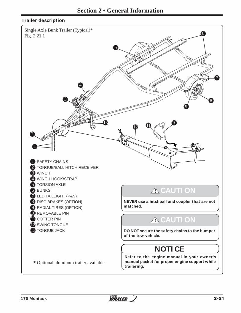
2-21170 Montauk
Section 2 • General Information
R
Single Axle Bunk Trailer (Typical)*Fig. 2.21.1
SAFETY CHAINSTONGUE/BALL HITCH RECEIVERWINCHWINCH HOOK/STRAPTORSION AXLEBUNKSLED TAILLIGHT (P&S)DISC BRAKES (OPTION)RADIAL TIRES (OPTION)REMOVABLE PINCOTTER PINSWING TONGUETONGUE JACK
123456789
NEVER use a hitchball and coupler that are not matched.
! CAUTION
DO NOT secure the safety chains to the bumper of the tow vehicle.
! CAUTION
Trailer description
Refer to the engine manual in your owner’s manual packet for proper engine support while trailering.
NOTICE
1
2
3
4
5
6
9
1013
10
8
11
* Optional aluminum trailer available
7
12
1112
13

2-22 170 Montauk
Section 2 • General Information
R
THIS PAGE INTENTIONALLY LEFT BLANK

3-1170 Montauk
Section 3 • Systems & Components Overview & Operation
The bilge pump located under the access hatch in the aft cockpit is rated at 1100 GPH (4164 LPH). The pump is activated automatically by a mercury-free fl oat switch when the water in the bilge reachs a predetermined level.
A switch on the console switch panel labeled BILGE PUMP (See fi gure 2.10.1) controls the operation of the pump. The switch should remain in the AUTO position while in use, unless the operator wishes to manually operate the pump by depressing the switch to the ON position.
Bilge Pump
Maintenance
Frequently inspect the area under the fl oat switch to ensure it is free from debris and gummy bilge oil. To clean, soak in heavy duty bilge cleaner for 10 minutes, agitating several times. Check for unrestricted operation of the fl oat. Repeat the cleaning procedure if necessary.
Inspect the bilge pump intakes and keep them free of dirt or material which may impede the fl ow of water through the pump.
To clean the pump strainer, depress the lock tabs on both sides of the pump and lift the pump motor.
If water does not come out of discharge hose:
1. Remove the motor module to see if the impeller rotates with the power on.
2. Remove any debris that may have accumulated in the nozzle section or strainer base.
3. Check hose and connection on hull side for debris and proper connections.
Fuel & Oil Spillage
Regulations prohibit discharging fuel or oily waste in navigable waters. Discharge is defi ned as any action which causes a fi lm, sheen or discoloration on the water surface, or causes a sludge or emulsion beneath the water surface. A common violation is bilge
Bilge Pump Fig. 3.1.2
12
BILGE PUMP (1100 GPH/4164 LPH)LIVEWELL PUMPBILGE PUMP DISCHARGE HOSE TO THRU HULL DRAIN
3
FWD
Bilge Pump Maintenance Fig. 3.1.3
123
BILGE PUMP (1100 GPH/4164 LPH)OUTLETWATER INTAKELOCKING TAB (ON EACH SIDE)
1
24
3
4
The bilge pump is wired directly to the battery. Therefore it is imperative that the fl oat switch remain clear of debris to prevent continuous operation and subsequentdischarge of the battery.
NOTICE
Bilge Pump SwitchFig. 3.1.1
12
BILGE PUMP “AUTO”BILGE PUMP “ON”
1
1
2
2
3
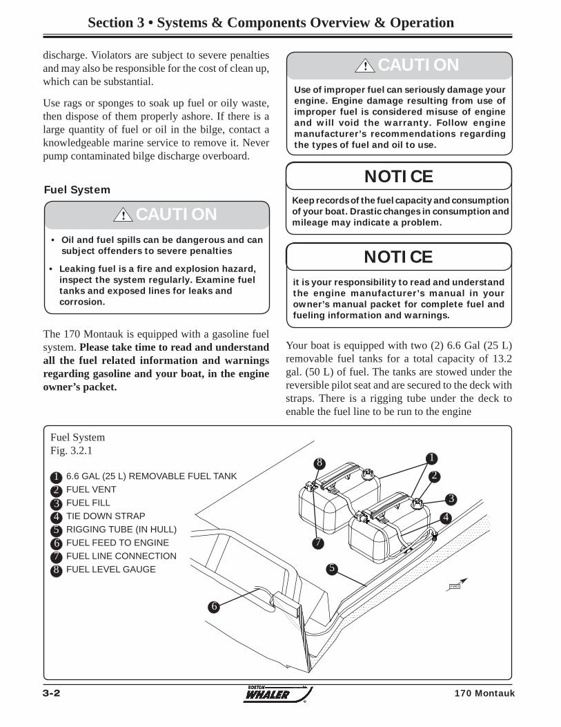
3-2 170 Montauk
Section 3 • Systems & Components Overview & Operation
Fuel SystemFig. 3.2.1
discharge. Violators are subject to severe penalties and may also be responsible for the cost of clean up, which can be substantial.
Use rags or sponges to soak up fuel or oily waste, then dispose of them properly ashore. If there is a large quantity of fuel or oil in the bilge, contact a knowledgeable marine service to remove it. Never pump contaminated bilge discharge overboard.
The 170 Montauk is equipped with a gasoline fuel system. Please take time to read and understand all the fuel related information and warnings regarding gasoline and your boat, in the engine owner’s packet.
Fuel System
Your boat is equipped with two (2) 6.6 Gal (25 L) removable fuel tanks for a total capacity of 13.2 gal. (50 L) of fuel. The tanks are stowed under the reversible pilot seat and are secured to the deck with straps. There is a rigging tube under the deck to enable the fuel line to be run to the engine
123
6.6 GAL (25 L) REMOVABLE FUEL TANKFUEL VENTFUEL FILLTIE DOWN STRAPRIGGING TUBE (IN HULL)FUEL FEED TO ENGINEFUEL LINE CONNECTIONFUEL LEVEL GAUGE
456
NOTICEit is your responsibility to read and understand the engine manufacturer’s manual in your owner’s manual packet for complete fuel and fueling information and warnings.
• Leaking fuel is a fi re and explosion hazard, inspect the system regularly. Examine fuel tanks and exposed lines for leaks and corrosion.
• Oil and fuel spills can be dangerous and can subject offenders to severe penalties
! CAUTIONKeep records of the fuel capacity and consumption of your boat. Drastic changes in consumption and mileage may indicate a problem.
NOTICE
! CAUTIONUse of improper fuel can seriously damage your engine. Engine damage resulting from use of improper fuel is considered misuse of engine and will void the warranty. Follow engine manufacturer’s recommendations regarding the types of fuel and oil to use.
12
3
4
5
6
7
8
78
FWD
3-3170 Montauk
Section 3 • Systems & Components Overview & Operation
There is a danger that static electricity can ignite gasoline vapors that have not been ventilated outside an enclosed area. Use extreme caution when fueling your boat from a source outside the regular venues, (e.g. marinas, fuel service stations).
Your boats bonding system protects it from creating and discharging static electricity. Your boat must be in contact with the water or a land based grounding system. The following suggestions will help keep you safe from static electricity while refueling your boat.
Your boat has safety features that can be circumvented by not adhering to standard fueling practices.
• NEVER fuel your boat in unsafe conditions such as suspended on a sling or in a situation that increases the liklihood of static discharge.
• NEVER use homemade containers to fi ll your fuel tanks.
• Fuel carr ied on-board outs ide of a fixed fuel system should be stored in an approved container or in a portable tank such as provided for outboard engines and be stowed safely outside of the engine or living compartment(s).
• Shut down the engine, motors and fans prior to taking on fuel. Any ignition sources should be extinguished before fi lling the fuel tank.
• Close all ports, windows, doors and hatches.
Static Electricity and the Fuel System
• Static electricity can ignite gasoline vapors causing serious injury or death and/or destruction of property.
! DANGER
• Check for leaks in tubing, connections and hoses. Avoid all forms of ignition when the odor of fuel is noticed. Correct the cause of the leaks and ventilate the area to insure that no fumes remain prior to energizing any electrical equipment, smoking and/or starting the engines.
REFER TO THE “DO’S AND DON’TS AT THE GAS PUMP” DVD IN YOUR OWNER’S MANUAL PACKET FOR MORE INFORMATION.
• Fueling should never be done at night except in well-lighted areas.
• Always keep the fuel nozzle in contact with the fuel fi ll plate or the edge of the fuel tank opening throughout the fi lling process.
• Allow areas where gasoline vapors could collect to be ventilated before starting the engine.
• Wipe any spillage completely and dispose of rags or waste on shore.
• Secure the fi ll cap tightly.
• Portable tanks should only be fi lled while on shore, never on board the boat.
Ethanol-Blended FuelsEthanol is an oxygenated hydrocarbon compound that has a high octane rating and therefore is useful in increasing the octane level of unleaded gasoline. The
fuel-system components of your Mercury engine(s) have been tested to perform with the maximum level of ethanol-blended gasoline (10% ethanol) currently allowed by the EPA in the United States.
Special precautions should be considered with the use of fuel containing ethanol in your system. Fuels with ethanol can attack some fuel-system components, such as tanks and lines, if they are not made from acceptable ethanol-compatible materials. This can lead to operational problems or safety issues such as clogged fi lters, leaks or engine damage.
The use of improper gasoline or additives can damage your fuel system and is considered misuse of the system. Damaged caused by improper gasoline or additives WILL NOT be covered under warranty.
NOTICE
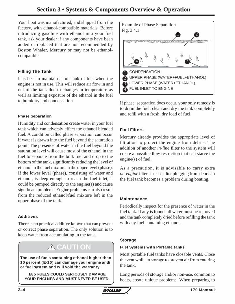
3-4 170 Montauk
Section 3 • Systems & Components Overview & Operation
If phase separation does occur, your only remedy is to drain the fuel, clean and dry the tank completely and refi ll with a fresh, dry load of fuel.
Fuel Filters
Mercury already provides the appropriate level of fi ltration to protect the engine from debris. The addition of another in-line fi lter to the system will create a possible fl ow restriction that can starve the engine(s) of fuel.
As a precaution, it is advisable to carry extra on-engine fi lters in case fi lter plugging from debris in the fuel tank becomes a problem during boating.
Periodically inspect for the presence of water in the fuel tank. If any is found, all water must be removed and the tank completely dried before refi lling the tank with any fuel containing ethanol.
Fuel Systems with Portable tanks:
Most portable fuel tanks have closable vents. Close the vent while in storage to prevent air from entering the tank.
Long periods of storage and/or non-use, common to boats, create unique problems. When preparing to
Example of Phase SeparationFig. 3.4.1
1234
1 2
34
The use of fuels containing ethanol higher than 10 percent (E-10) can damage your engine and/or fuel system and will void the warranty.
! CAUTION
E85 FUELS COULD SERIOUSLY DAMAGE YOUR ENGINES AND MUST NEVER BE USED.
CONDENSATIONUPPER PHASE (WATER+FUEL+ETHANOL)LOWER PHASE (WATER+ETHANOL)FUEL INLET TO ENGINE
Maintenance
Storage
Your boat was manufactured, and shipped from the factory, with ethanol-compatible materials. Before introducing gasoline with ethanol into your fuel tank, ask your dealer if any components have been added or replaced that are not recommended by Boston Whaler, Mercury or may not be ethanol-compatible.
Filling The Tank
It is best to maintain a full tank of fuel when the engine is not in use. This will reduce air fl ow in and out of the tank due to changes in temperature as well as limiting exposure of the ethanol in the fuel to humidity and condensation.
Phase Separation
Humidity and condensation create water in your fuel tank which can adversly effect the ethanol blended fuel. A condition called phase separation can occur if water is drawn into the fuel beyond the saturation point. The presence of water in the fuel beyond the saturation level will cause most of the ethanol in the fuel to separate from the bulk fuel and drop to the bottom of the tank, signifi cantly reducing the level of ethanol in the fuel mixture in the upper level (phase). If the lower level (phase), consisting of water and ethanol, is deep enough to reach the fuel inlet, it could be pumped directly to the engine(s) and cause signifi cant problems. Engine problems can also result from the reduced ethanol/fuel mixture left in the upper phase of the tank.
Additives
There is no practical additive known that can prevent or correct phase separation. The only solution is to keep water from accumulating in the tank.
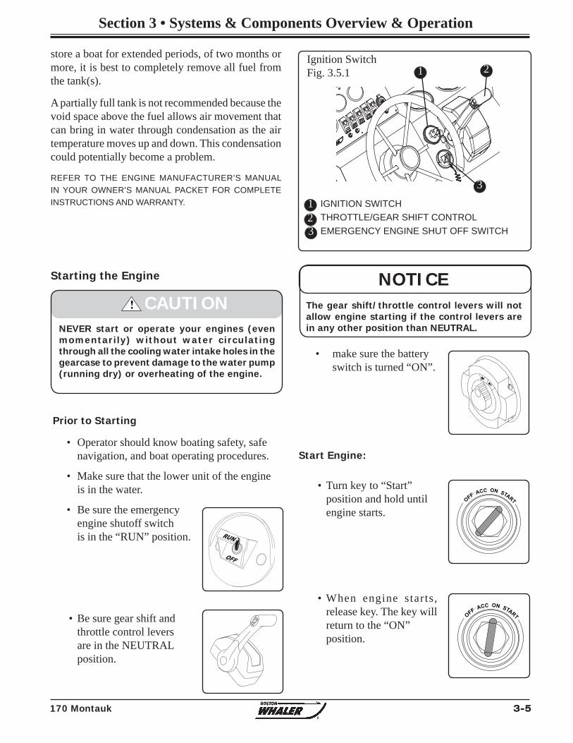
3-5170 Montauk
Section 3 • Systems & Components Overview & Operation
store a boat for extended periods, of two months or more, it is best to completely remove all fuel from the tank(s).
A partially full tank is not recommended because the void space above the fuel allows air movement that can bring in water through condensation as the air temperature moves up and down. This condensation could potentially become a problem.
• make sure the battery switch is turned “ON”.
Start Engine:
• Turn key to “Start” position and hold until engine starts.
• When engine starts, release key. The key will return to the “ON” position.
Starting the Engine
! CAUTIONNEVER start or operate your engines (even momentarily) without water circulating through all the cooling water intake holes in the gearcase to prevent damage to the water pump (running dry) or overheating of the engine.
• Operator should know boating safety, safe navigation, and boat operating procedures.
• Make sure that the lower unit of the engine is in the water.
• Be sure the emergency engine shutoff switch is in the “RUN” position.
• Be sure gear shift and throttle control levers are in the NEUTRAL position.
Prior to Starting
NOTICEThe gear shift/throttle control levers will not allow engine starting if the control levers are in any other position than NEUTRAL.
Ignition SwitchFig. 3.5.1
12
IGNITION SWITCHTHROTTLE/GEAR SHIFT CONTROLEMERGENCY ENGINE SHUT OFF SWITCH
1
DNUP
O
FF ACC ON START
O
FF ACC ON START
OFF
RUN
3
3
2
REFER TO THE ENGINE MANUFACTURER’S MANUAL IN YOUR OWNER’S MANUAL PACKET FOR COMPLETE INSTRUCTIONS AND WARRANTY.
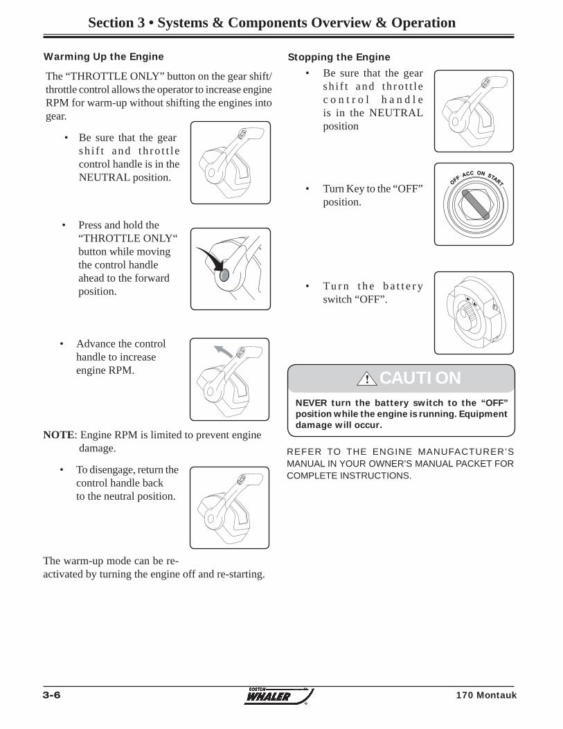
3-6 170 Montauk
Section 3 • Systems & Components Overview & Operation
Warming Up the Engine
The “THROTTLE ONLY” button on the gear shift/throttle control allows the operator to increase engine RPM for warm-up without shifting the engines into gear.
• Be sure that the gear sh i f t and th ro t t l e control handle is in the NEUTRAL position.
Stopping the Engine• Be sure that the gear sh i f t and th ro t t l e c o n t r o l h a n d l e is in the NEUTRAL position
• Turn Key to the “OFF” position.
• Tu r n t h e b a t t e r y switch “OFF”.
• Press and hold the “THROTTLE ONLY“ button while moving the control handle ahead to the forward position.
REFER TO THE ENGINE MANUFACTURER’S MANUAL IN YOUR OWNER’S MANUAL PACKET FOR COMPLETE INSTRUCTIONS.
DNUP
• Advance the control handle to increase engine RPM.
NOTE: Engine RPM is limited to prevent engine damage.
• To disengage, return the control handle back to the neutral position.
The warm-up mode can be re-activated by turning the engine off and re-starting.
DNUP
DNUP
O
FF ACC ON START
DNUP
! CAUTIONNEVER turn the battery switch to the “OFF” position while the engine is running. Equipment damage will occur.
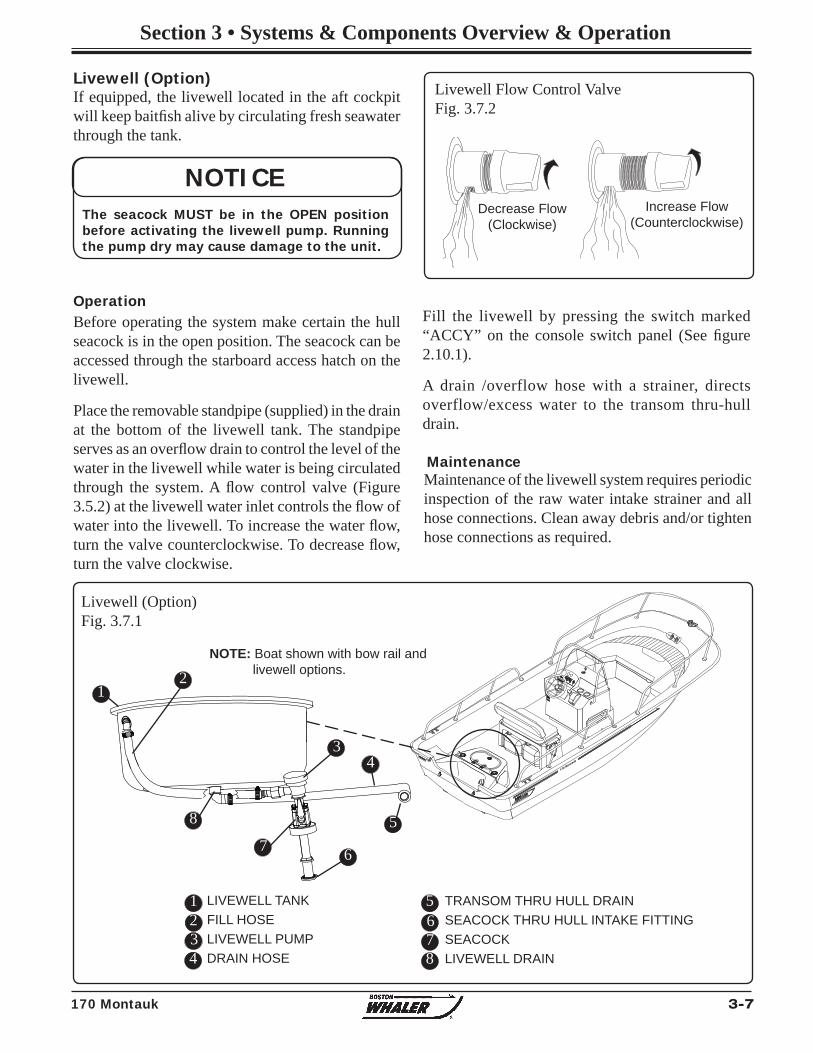
3-7170 Montauk
Section 3 • Systems & Components Overview & Operation
Livewell (Option) If equipped, the livewell located in the aft cockpit will keep baitfi sh alive by circulating fresh seawater through the tank.
Before operating the system make certain the hull seacock is in the open position. The seacock can be accessed through the starboard access hatch on the livewell.
Place the removable standpipe (supplied) in the drain at the bottom of the livewell tank. The standpipe serves as an overfl ow drain to control the level of the water in the livewell while water is being circulated through the system. A fl ow control valve (Figure 3.5.2) at the livewell water inlet controls the fl ow of water into the livewell. To increase the water fl ow, turn the valve counterclockwise. To decrease fl ow, turn the valve clockwise.
Maintenance of the livewell system requires periodic inspection of the raw water intake strainer and all hose connections. Clean away debris and/or tighten hose connections as required.
Maintenance
Operation
NOTICEThe seacock MUST be in the OPEN position before activating the livewell pump. Running the pump dry may cause damage to the unit.
Fill the livewell by pressing the switch marked “ACCY” on the console switch panel (See fi gure 2.10.1).
A drain /overflow hose with a strainer, directs overflow/excess water to the transom thru-hull drain.
Livewell (Option)Fig. 3.7.1
123
LIVEWELL TANKFILL HOSELIVEWELL PUMPDRAIN HOSE4
5678
21
3
5
67
8
NOTE: Boat shown with bow rail and livewell options.
4
TRANSOM THRU HULL DRAINSEACOCK THRU HULL INTAKE FITTINGSEACOCKLIVEWELL DRAIN
Livewell Flow Control ValveFig. 3.7.2
Decrease Flow(Clockwise)
Increase Flow(Counterclockwise)
170 Montauk
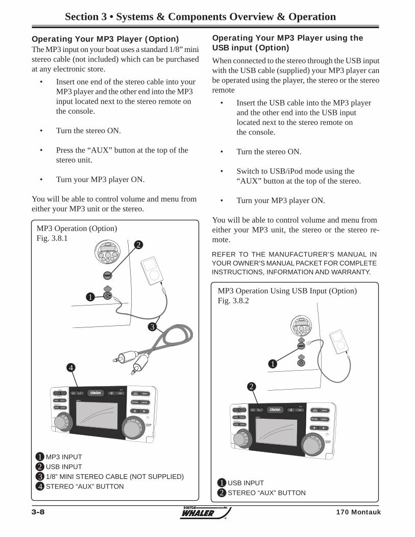
3-8 170 Montauk
Section 3 • Systems & Components Overview & Operation
UP/DOWNSELECT
ENTER
MENUMUTE
RETURN
IISATAM
CAT
FMDISC AUXiPod
CMV1AUDIO DISPLAY
OPTION ADJUST
POWER
MONI OFF
VOLUME
DVD SET-UP
UP/DOWNSELECT
ENTER
MENUMUTE
RETURN
IISATAM
CAT
FMDISC AUXiPod
CMV1AUDIO DISPLAY
OPTION ADJUST
POWER
MONI OFF
VOLUME
DVD SET-UP
The MP3 input on your boat uses a standard 1/8” mini stereo cable (not included) which can be purchased at any electronic store. • Insert one end of the stereo cable into your
MP3 player and the other end into the MP3 input located next to the stereo remote on the console.
• Turn the stereo ON.
• Press the “AUX” button at the top of the stereo unit.
• Turn your MP3 player ON.
You will be able to control volume and menu fromeither your MP3 unit or the stereo.
Operating Your MP3 Player (Option)
MP3 Operation (Option)Fig. 3.8.1
1
32
MP3 INPUT USB INPUT1/8” MINI STEREO CABLE (NOT SUPPLIED)STEREO “AUX” BUTTON
1
3
4
2
4
When connected to the stereo through the USB input with the USB cable (supplied) your MP3 player can be operated using the player, the stereo or the stereo remote • Insert the USB cable into the MP3 player
and the other end into the USB input located next to the stereo remote on the console.
• Turn the stereo ON.
• Switch to USB/iPod mode using the “AUX” button at the top of the stereo.
• Turn your MP3 player ON.
You will be able to control volume and menu fromeither your MP3 unit, the stereo or the stereo re-mote.
Operating Your MP3 Player using the USB input (Option)
MP3 Operation Using USB Input (Option)Fig. 3.8.2
12
USB INPUTSTEREO “AUX” BUTTON
1
2
REFER TO THE MANUFACTURER’S MANUAL IN YOUR OWNER’S MANUAL PACKET FOR COMPLETE INSTRUCTIONS, INFORMATION AND WARRANTY.
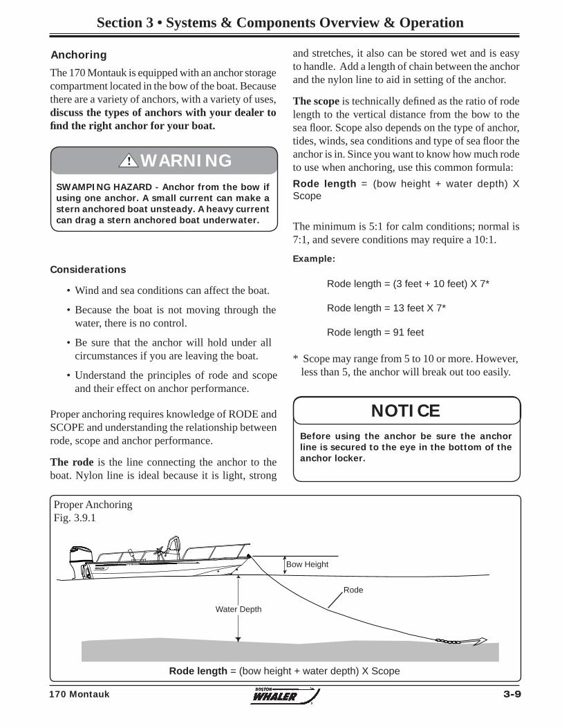
3-9170 Montauk
Section 3 • Systems & Components Overview & Operation
170 Montauk
R
Anchoring
The 170 Montauk is equipped with an anchor storage compartment located in the bow of the boat. Because there are a variety of anchors, with a variety of uses, discuss the types of anchors with your dealer to fi nd the right anchor for your boat.
Considerations
• Wind and sea conditions can affect the boat.
• Because the boat is not moving through the water, there is no control.
• Be sure that the anchor will hold under all circumstances if you are leaving the boat.
• Understand the principles of rode and scope and their effect on anchor performance.
Proper anchoring requires knowledge of RODE and SCOPE and understanding the relationship between rode, scope and anchor performance.
The rode is the line connecting the anchor to the boat. Nylon line is ideal because it is light, strong
and stretches, it also can be stored wet and is easy to handle. Add a length of chain between the anchor and the nylon line to aid in setting of the anchor.
The scope is technically defi ned as the ratio of rode length to the vertical distance from the bow to the sea fl oor. Scope also depends on the type of anchor, tides, winds, sea conditions and type of sea fl oor the anchor is in. Since you want to know how much rode to use when anchoring, use this common formula:Rode length = (bow height + water depth) X Scope
The minimum is 5:1 for calm conditions; normal is 7:1, and severe conditions may require a 10:1.
Example:
Bow Height
Water Depth
Rode
Rode length = (3 feet + 10 feet) X 7*
Rode length = 13 feet X 7*
Rode length = 91 feet
* Scope may range from 5 to 10 or more. However, less than 5, the anchor will break out too easily.
Proper AnchoringFig. 3.9.1
Rode length = (bow height + water depth) X Scope
SWAMPING HAZARD - Anchor from the bow if using one anchor. A small current can make a stern anchored boat unsteady. A heavy current can drag a stern anchored boat underwater.
! WARNING
NOTICEBefore using the anchor be sure the anchor line is secured to the eye in the bottom of the anchor locker.
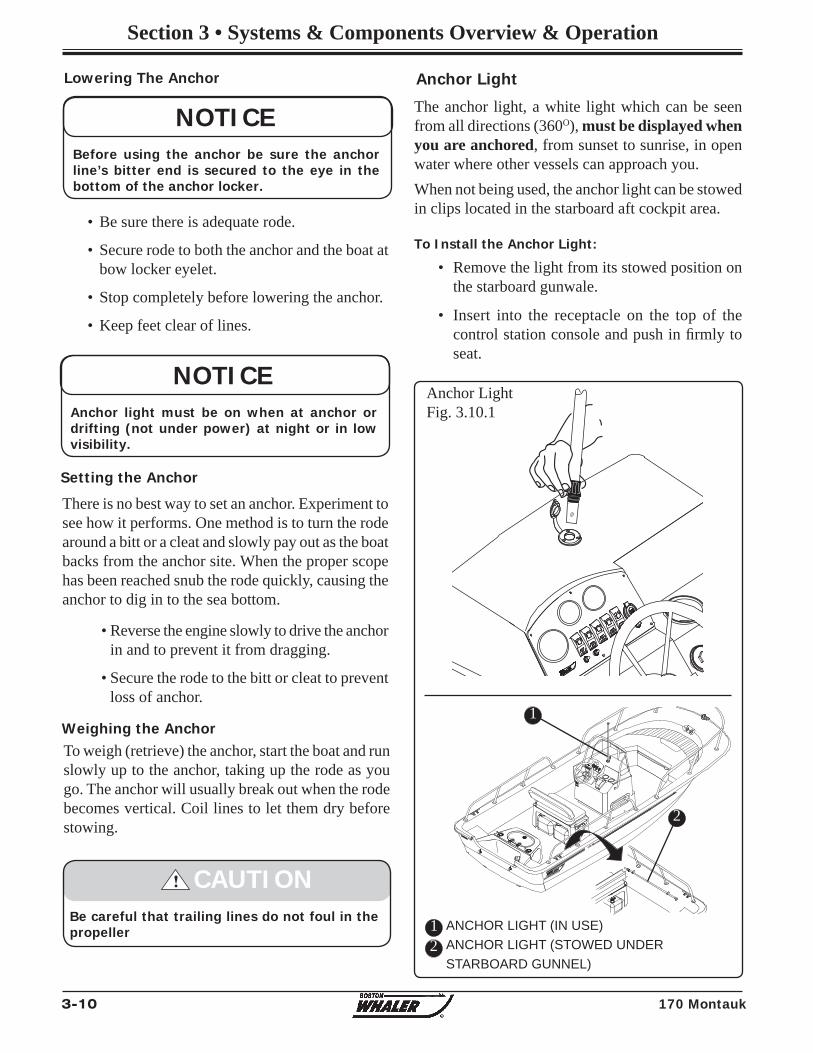
3-10 170 Montauk
Section 3 • Systems & Components Overview & Operation
170 Montauk
• Be sure there is adequate rode.
• Secure rode to both the anchor and the boat at bow locker eyelet.
• Stop completely before lowering the anchor.
• Keep feet clear of lines.
To weigh (retrieve) the anchor, start the boat and run slowly up to the anchor, taking up the rode as you go. The anchor will usually break out when the rode becomes vertical. Coil lines to let them dry before stowing.
Weighing the Anchor
There is no best way to set an anchor. Experiment to see how it performs. One method is to turn the rode around a bitt or a cleat and slowly pay out as the boat backs from the anchor site. When the proper scope has been reached snub the rode quickly, causing the anchor to dig in to the sea bottom.
• Reverse the engine slowly to drive the anchor in and to prevent it from dragging.
• Secure the rode to the bitt or cleat to prevent loss of anchor.
Setting the Anchor
Lowering The Anchor
NOTICEAnchor light must be on when at anchor or drifting (not under power) at night or in low visibility.
Be careful that trailing lines do not foul in the propeller
! CAUTION
NOTICEBefore using the anchor be sure the anchor line’s bitter end is secured to the eye in the bottom of the anchor locker.
Anchor Light
The anchor light, a white light which can be seen from all directions (360O), must be displayed when you are anchored, from sunset to sunrise, in open water where other vessels can approach you.When not being used, the anchor light can be stowed in clips located in the starboard aft cockpit area.
To Install the Anchor Light:
• Remove the light from its stowed position on the starboard gunwale.
• Insert into the receptacle on the top of the control station console and push in fi rmly to seat.
Anchor LightFig. 3.10.1
12
ANCHOR LIGHT (IN USE)ANCHOR LIGHT (STOWED UNDERSTARBOARD GUNNEL)
1
2
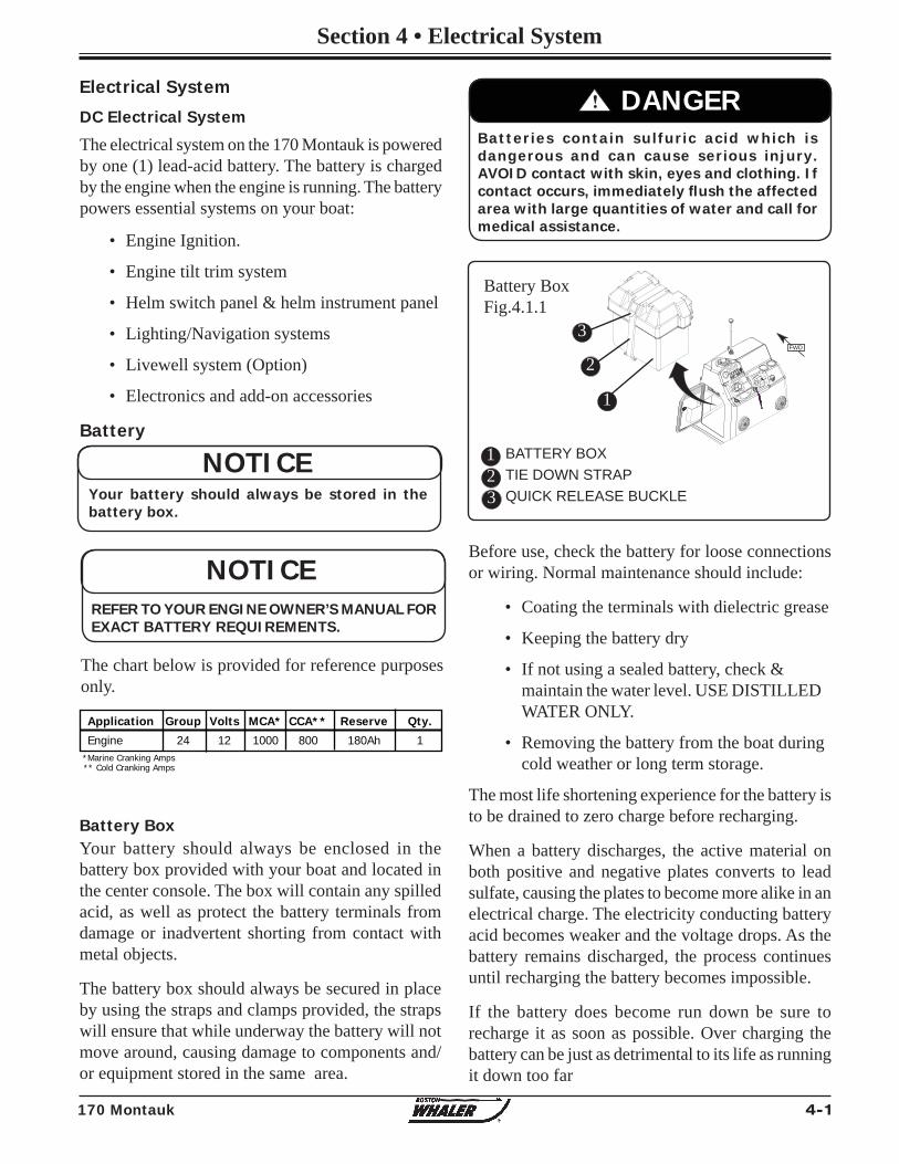
4-1170 Montauk
Section 4 • Electrical System
Electrical System
DC Electrical System
The electrical system on the 170 Montauk is powered by one (1) lead-acid battery. The battery is charged by the engine when the engine is running. The battery powers essential systems on your boat:
• Engine Ignition.
• Engine tilt trim system
• Helm switch panel & helm instrument panel
• Lighting/Navigation systems
• Livewell system (Option)
• Electronics and add-on accessories
Battery
Your battery should always be enclosed in the battery box provided with your boat and located in the center console. The box will contain any spilled acid, as well as protect the battery terminals from damage or inadvertent shorting from contact with metal objects.
The battery box should always be secured in place by using the straps and clamps provided, the straps will ensure that while underway the battery will not move around, causing damage to components and/or equipment stored in the same area.
Battery BoxFig.4.1.1
1 BATTERY BOXTIE DOWN STRAPQUICK RELEASE BUCKLE
Battery Box
2
FWD
Before use, check the battery for loose connections or wiring. Normal maintenance should include:
• Coating the terminals with dielectric grease
• Keeping the battery dry
• If not using a sealed battery, check & maintain the water level. USE DISTILLED WATER ONLY.
• Removing the battery from the boat during cold weather or long term storage.
The most life shortening experience for the battery is to be drained to zero charge before recharging.
When a battery discharges, the active material on both positive and negative plates converts to lead sulfate, causing the plates to become more alike in an electrical charge. The electricity conducting battery acid becomes weaker and the voltage drops. As the battery remains discharged, the process continues until recharging the battery becomes impossible.
If the battery does become run down be sure to recharge it as soon as possible. Over charging the battery can be just as detrimental to its life as running it down too far
Batteries contain sulfuric acid which is dangerous and can cause serious injury. AVOID contact with skin, eyes and clothing. If contact occurs, immediately fl ush the affected area with large quantities of water and call for medical assistance.
! DANGER
1
2
3
3
NOTICEYour battery should always be stored in the battery box.
Application Group Volts MCA* CCA** Reserve Qty.
Engine 24 12 1000 800 180Ah 1 *Marine Cranking Amps** Cold Cranking Amps
The chart below is provided for reference purposes only.
NOTICEREFER TO YOUR ENGINE OWNER’S MANUAL FOR EXACT BATTERY REQUIREMENTS.
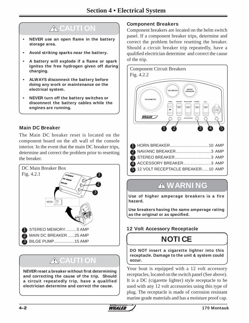
4-2 170 Montauk
Section 4 • Electrical System
STEREO MEMORY ..........5 AMPMAIN DC BREAKER ......25 AMPBILGE PUMP ..................15 AMP
Main DC BreakerThe Main DC breaker reset is located on the component board on the aft wall of the console interior. In the event that the main DC breaker trips, determine and correct the problem prior to resetting the breaker.
Component BreakersComponent breakers are located on the helm switch panel. If a component breaker trips, determine and correct the problem before resetting the breaker. Should a circuit breaker trip repeatedly, have a qualifi ed electrician determine and correct the cause of the trip.
Component Circuit BreakersFig. 4.2.2
12
HORN BREAKER ..................................10 AMPNAV/ANC BREAKER ...............................3 AMPSTEREO BREAKER................................3 AMPACCESSORY BREAKER ........................3 AMP12 VOLT RECEPTACLE BREAKER......10 AMP
3
• NEVER use an open fl ame in the battery storage area.
• Avoid striking sparks near the battery.
• A battery will explode if a fl ame or spark ignites the free hydrogen given off during charging.
• ALWAYS disconnect the battery before doing any work or maintenance on the electrical system.
• NEVER turn off the battery switches or disconnect the battery cables while the engines are running.
! CAUTION
DC Main Breaker BoxFig. 4.2.1
12
1
2
12 Volt Accessory Receptacle
Your boat is equipped with a 12 volt accessory receptacles, located on the switch panel (See above). It is a DC (cigarette lighter) style receptacle to be used with any 12 volt accessories using this type of plug. The receptacle is made of corrosion resistant marine grade materials and has a moisture proof cap.
NOTICEDO NOT insert a cigarette lighter into this receptacle. Damage to the unit & system could occur.
NEVER reset a breaker without fi rst determining and correcting the cause of the trip. Should a circuit repeatedly trip, have a qualified electrician determine and correct the cause.
! CAUTION
Use of higher amperage breakers is a fire hazard.
Use breakers having the same amperage rating as the original or as specifi ed.
! WARNING
45
3
3
12V
TACHOMETERNAV/ANC BILGE PUMP ACCSTEREOHORN
WATERPRESSUREVOLTMETER
R OFF/AUTO/ON
1 2 3 4 5
DC MAINBILGE
STEREO
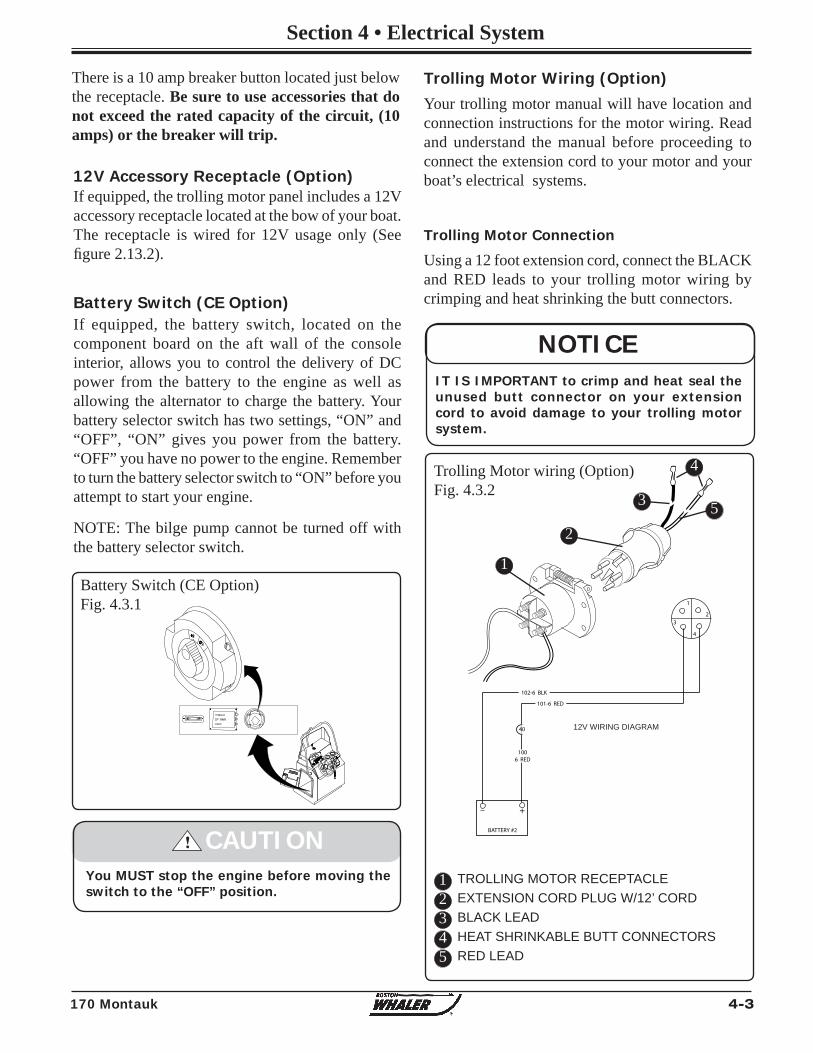
4-3170 Montauk
Section 4 • Electrical System
BATTERY #2
+
1
2
4
3
102-6 BLK
101-6 RED
1006 RED
40
There is a 10 amp breaker button located just below the receptacle. Be sure to use accessories that do not exceed the rated capacity of the circuit, (10 amps) or the breaker will trip.
If equipped, the trolling motor panel includes a 12V accessory receptacle located at the bow of your boat. The receptacle is wired for 12V usage only (See fi gure 2.13.2).
12V Accessory Receptacle (Option)
NOTICEIT IS IMPORTANT to crimp and heat seal the unused butt connector on your extension cord to avoid damage to your trolling motor system.
Trolling Motor wiring (Option)Fig. 4.3.2
12V WIRING DIAGRAM
12
TROLLING MOTOR RECEPTACLEEXTENSION CORD PLUG W/12’ CORDBLACK LEADHEAT SHRINKABLE BUTT CONNECTORSRED LEAD
345
2
3
4
5
Trolling Motor Wiring (Option)Your trolling motor manual will have location and connection instructions for the motor wiring. Read and understand the manual before proceeding to connect the extension cord to your motor and your boat’s electrical systems.
Trolling Motor Connection
Using a 12 foot extension cord, connect the BLACK and RED leads to your trolling motor wiring by crimping and heat shrinking the butt connectors.
If equipped, the battery switch, located on the component board on the aft wall of the console interior, allows you to control the delivery of DC power from the battery to the engine as well as allowing the alternator to charge the battery. Your battery selector switch has two settings, “ON” and “OFF”, “ON” gives you power from the battery. “OFF” you have no power to the engine. Remember to turn the battery selector switch to “ON” before you attempt to start your engine.
NOTE: The bilge pump cannot be turned off with the battery selector switch.
Battery Switch (CE Option)Fig. 4.3.1
You MUST stop the engine before moving the switch to the “OFF” position.
! CAUTION
Battery Switch (CE Option)
1
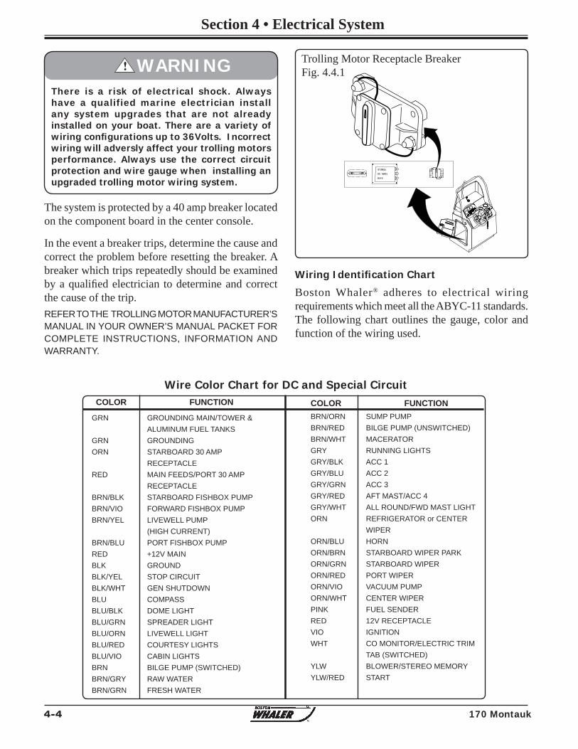
4-4 170 Montauk
Section 4 • Electrical System
Wiring Identifi cation Chart
Boston Whaler® adheres to electrical wiring requirements which meet all the ABYC-11 standards. The following chart outlines the gauge, color and function of the wiring used.
REFER TO THE TROLLING MOTOR MANUFACTURER’S MANUAL IN YOUR OWNER’S MANUAL PACKET FOR COMPLETE INSTRUCTIONS, INFORMATION AND WARRANTY.
Trolling Motor Receptacle BreakerFig. 4.4.1
There is a risk of electrical shock. Always have a qualified marine electrician install any system upgrades that are not already installed on your boat. There are a variety of wiring confi gurations up to 36Volts. Incorrect wiring will adversly affect your trolling motors performance. Always use the correct circuit protection and wire gauge when installing an upgraded trolling motor wiring system.
! WARNING
The system is protected by a 40 amp breaker located on the component board in the center console.
In the event a breaker trips, determine the cause and correct the problem before resetting the breaker. A breaker which trips repeatedly should be examined by a qualifi ed electrician to determine and correct the cause of the trip.
BRN/ORN SUMP PUMP BRN/RED BILGE PUMP (UNSWITCHED) BRN/WHT MACERATOR GRY RUNNING LIGHTS GRY/BLK ACC 1 GRY/BLU ACC 2 GRY/GRN ACC 3 GRY/RED AFT MAST/ACC 4 GRY/WHT ALL ROUND/FWD MAST LIGHT ORN REFRIGERATOR or CENTER WIPER ORN/BLU HORN ORN/BRN STARBOARD WIPER PARK ORN/GRN STARBOARD WIPER ORN/RED PORT WIPER ORN/VIO VACUUM PUMP ORN/WHT CENTER WIPER PINK FUEL SENDER RED 12V RECEPTACLE VIO IGNITION WHT CO MONITOR/ELECTRIC TRIM TAB (SWITCHED) YLW BLOWER/STEREO MEMORY YLW/RED START
COLOR FUNCTION
GRN GROUNDING MAIN/TOWER & ALUMINUM FUEL TANKS GRN GROUNDING ORN STARBOARD 30 AMP RECEPTACLE RED MAIN FEEDS/PORT 30 AMP RECEPTACLE BRN/BLK STARBOARD FISHBOX PUMP BRN/VIO FORWARD FISHBOX PUMP BRN/YEL LIVEWELL PUMP (HIGH CURRENT) BRN/BLU PORT FISHBOX PUMP RED +12V MAIN BLK GROUND BLK/YEL STOP CIRCUIT BLK/WHT GEN SHUTDOWN BLU COMPASS BLU/BLK DOME LIGHT BLU/GRN SPREADER LIGHT BLU/ORN LIVEWELL LIGHT BLU/RED COURTESY LIGHTS BLU/VIO CABIN LIGHTS BRN BILGE PUMP (SWITCHED) BRN/GRY RAW WATER BRN/GRN FRESH WATER
COLOR FUNCTION
Wire Color Chart for DC and Special Circuit
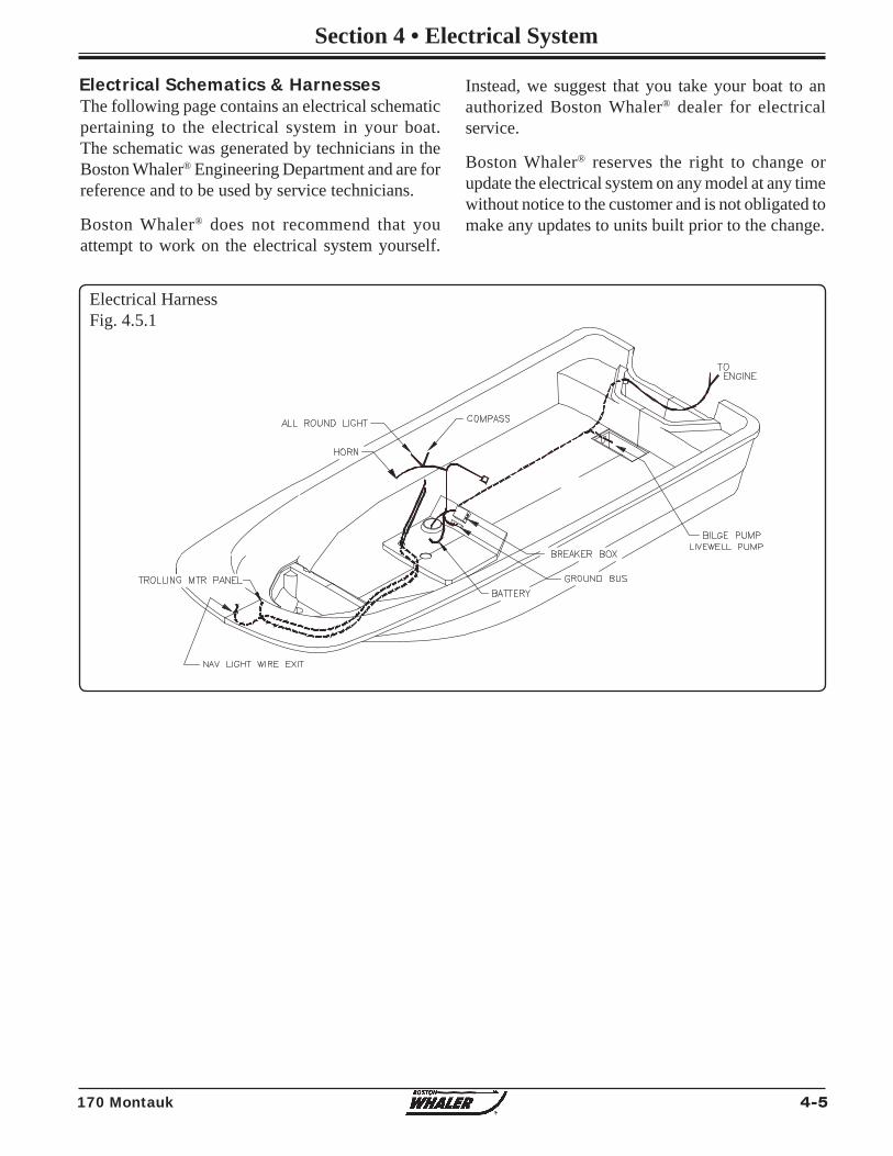
4-5170 Montauk
Section 4 • Electrical System
The following page contains an electrical schematic pertaining to the electrical system in your boat. The schematic was generated by technicians in the Boston Whaler® Engineering Department and are for reference and to be used by service technicians.
Boston Whaler® does not recommend that you attempt to work on the electrical system yourself.
Electrical Schematics & Harnesses Instead, we suggest that you take your boat to an authorized Boston Whaler® dealer for electrical service.
Boston Whaler® reserves the right to change or update the electrical system on any model at any time without notice to the customer and is not obligated to make any updates to units built prior to the change.
Electrical HarnessFig. 4.5.1
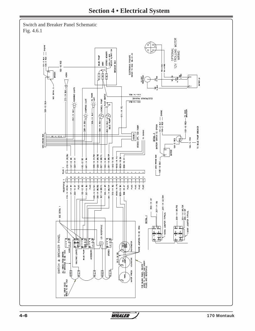
4-6 170 Montauk
Section 4 • Electrical System
Switch and Breaker Panel SchematicFig. 4.6.1
5-1
Section 5 • Care & Maintenance
R
170 Montauk
Routine Care & Maintenance
Routine inspection, service and maintenance of your boat, boat systems and components are vital to assure your safety, as well as prolonging the life of your boat. You should develop regular routines for inspecting and servicing your boat.
The interval between necessary service or maintenance is highly variable, depending on the environment in which your boat will be used. For example, corrosion of boat parts and components will occur far more rapidly in a salt water environment than on a boat which is used in fresh water.
This section provides only general guidelines for the care and cleaning of your boat. It is your responsibility to determine whether maintenance and care intervals need to be accelerated due to your boat usage and/or operating environment.
Fresh water, saltwater and water temperature can all affect the types of growth that you will fi nd on your boat’s hull.
Any growth will affect the boat’s performance and overall look. If it has been a while between inspections you might notice algae or slime growth on the hull. This can be cleaned with a coarse towel or soft bristle brush. The growth should be cleaned immediately after the boat has been removed from the water. If the growth is allowed to dry it will be much harder to remove.
Compounding may be necessary to remove more stubborn stains and chalking from the surface of your boat. If compounding is necessary it must be done after a thorough washing and prior to waxing.
If the growth is more severe, you may need to enlist the services of a professional hull cleaning company.
Check with your Boston Whaler® dealer for recommendations on a compatible rubbing compound for your boat or a professional hull cleaning company in your area.
Waxing the Gel Coat Surfaces
Waxing is necessary to provide added protection to the gel coat. A periodic good cleaning and waxing will also ensure that your boat will be protected and look good longer.
Do not wax over dirt. Make sure the surface of your boat has received a thorough washing and rinsing and is clean before waxing. If a rubbing compound has been necessary, make sure that any minor scratches or surface pitting is cleaned of compound residue. Use a good quality carnauba wax or a high quality wax designed for marine gel coat. Apply several coats.
Hull
NOTICERefer to the individual manufacturers’ manuals for important information regarding service, care and maintenance of your boat, equipment and components. Failure to do so may in some cases void the warranty.
Owner’s Manuals for your boat and each of the various components and equipment can be found in your Owner’s Manual Packet.
When using solvents read all information from the solvent manufacturer regarding safety and handling of the material.
Wear proper protective equipment to ensure your personal safety.
Only use solvents in a well ventilated area and keep all solvents away from open fl ame and any other forms of ignition.
! DANGER
NOTICEWaxing of the exterior surfaces is recommended to be done at least twice a year to protect the gel coat of your boat.
5-2
Section 5 • Care & Maintenance
R
170 Montauk
Hull Maintenance
If using a pressure washer to clean the hull and deck surfaces of your boat it is important that you use the wide fan nozzle only and move the spray head in a continuous motion. Do not concentrate the high pressure on a small area of the boat surface and NEVER use the fi ne pinpoint nozzle as the concentrated stream can cause damage to the surface of your boat.
It is also recommended that your refrain from pressure washing the console as high pressure may compromise the integrity of the electronics and gauges as well as other equipment installed on your boat. Also avoid pressure washing all caulk seams.
When staining from build-up does occur, use only cleaning agents that are recommended for marine gel coat for use on those stubborn stains.
NEVER use an abrasive cleaner to wash your boat’s hull.
NEVER use an abrasive pad to attempt to remove stubborn stains.
NEVER use strong solvents to clean.
NEVER apply tape or any other type of adhesives directly to the painted surfaces on your boat.
Use care when covering your boat’s painted surfaces as tarps and other such covers can trap dirt and cause chafi ng. It is best to use a frame of either aluminum or wood to keep the cover up and allow air to circulate.
Hull Blistering
Due to the quality of the materials used in the hulls of Boston Whalers, blistering is rarely ever seen. Blistering is caused by water soluble materials in the hull laminate. The fi berglass and resin structure of your boat is porous. However, intrusion of water into the gel coat will take some time. The effect of osmotic pressure allows water to impregnate below the gel coat and substrate thus forming a blister.
Bottom Painting
There are risks and dangers inherent with the use of paints and solvents. Dispose properly of all rags, rollers and trays used for painting. Follow all the precautions and regulations listed by the manufacturer before and after painting your boats hull.
! DANGER
NOTICEIf blisters are present in the hull, they need to be properly cleaned and dried out before any barrier protection can be applied.
There have been extensive university studies funded by the United States Coast Guard regarding the cause and effect of blistering in the gel coat of fi berglass boats. Fiberglass blisters can form anywhere from near-surface layers of the gel coat to very deep into the fi berglass structure. The damage can range from cosmetic to catastrophic, (although the latter is a very rare occurrence). The studies seemed to point toward long term immersion of the hull in warm water as a primary cause of hull blisters. Stress cracks on the hull below the waterline also contribute to the formation of hull blisters.
Prevention
There are a variety of ways to prevent the formation of hull blistering. Epoxy coatings can be applied to the hull, followed by hull painting. An alkyd-urethane-silicone marine paint can also be used to aid in the prevention of hull blisters.
Reducing the amount of time that your boat stays in the water also helps prevent hull blisters from forming. Use of a trailer or boat lift will reduce the likelihood of hull blisters forming. Be sure to use a bunk type lift or trailer for storage of the boat out of water.
Contact your Boston Whaler® dealer for more information on the prevention and treatment of hull blisters.
5-3
Section 5 • Care & Maintenance
R
170 Montauk
will be dragged into the scratches and will reduce the adhesion properties of the paint.
Remove any mold release wax that may be present using fi berglass surface prep solvent and a scrub pad. Scrub only a few square feet at a time. Flush with fresh water. If the water beads up or separates, continue scrubbing the surface. When the water sheets off, the wax contaminate has been removed.
After the dewaxing is complete, application of a primer coat is recommended. Pay close attention to scratches, nicks and dings in the surface. If necessary, fi ll any repair areas with a watertite epoxy fi ller. After fi ller is cured, sand with 80 grit paper until smooth. Remove the sanding residue using a fi berglass solvent wash.
The paint can be applied after sanding and cleaning is complete. Follow the paint manufacturer’s recommendations for application.
Bottom Painting a Pre-Painted Hull
If the hull bottom is already painted, you must be sure to test the paint’s adhesion to the already painted surface. If the paints are incompatible, the new paint will not adhere to the hull bottom or the paint will “lift” the old paint. NEVER apply paint without fi rst preparing the old painted surface following the paint manufacturer’s recommendations.
Follow the paint manufacturer’s recommendation for applying the paint. Humidity and weather will play a role in how and when the paint is applied. Several thin layers are better than one thick layer.
To determine the waterline, you will need to place the boat in water with a full load of fuel and gear.Mark the waterline and measure above the marked line 1 to 3 inches for placement of the tape line.
! WARNINGProper ventilation and capture of the dust created by sanding is essential. The dust created by sanding is toxic and should not be breathed. A proper fi tting respirator must be used.
DO NOT use a paper fi lter mask.
! WARNINGBottom paint is designed to resist algae growth which means it has chemicals embedded in the paint that are harmful if ingested. Take all necessary precautions required before painting or repainting your boat’s hull.
If your boat will spend most of its time in the water, painting the bottom of your boat’s hull is a good way to slow the formation of hull blisters and to keep bottom growth (fouling) under control.
If you will be trailering the boat to and from the water, you might want to forgo the painting.
Following is an abbreviated section on painting your hull bottom. Your Boston Whaler® dealer should have information on properly painting your boat’s hull or recommendations on businesses that will paint your hull for you.
Bottom Painting a Bare Hull
Since the boat has never been painted preparation is the key to successful hull painting. Take extra care and time in preparation before proceeding to paint.
Begin by scrubbing the surface thoroughly with a stiff brush using an all-purpose marine soap and water to remove loose dirt and contamination. Flush with fresh water to remove all soap residue.
The gelcoat will have to be dewaxed of mold release wax before sanding can begin, otherwise the wax
DO NOT paint over zinc plates. This action will render them usless and lead to deterioration of the underwater metal parts of your boat.
Some bottom paints contain metals that can cause corrosion of the outboard engine. Leave a minimum of 3/4” unpainted around all engine parts. Use only a paint specifi cally designed for aluminum engines as anti fouling protection.
! CAUTION
5-4
Section 5 • Care & Maintenance
R
170 Montauk
Rubrail CareThe rubrail on your boat is constructed of an injected high density PVC vinyl material which laboratory tests have proven to be highly resistant to staining, fading and cracking.
As resilient as this material is, you still need to follow some basic maintenance precautions.
General maintenance requires a thorough cleaning with mild soap & water. DO NOT use any cleaning agents which contain chemicals.
Although the outer shell is tough and durable, there is a chance that it can be breached. Use care when docking or exposing the rubrail to conditions which may cause damage such as docking against heavily barnacle-encrusted pilings.
Some tears (cleanly sliced) can be repaired with a “Super Glue” type product.
Thoroughly clean and dry the affected area. Apply glue and hold the surfaces together.
Areas which have been torn or are affected by heavy abrasion will have to have the damaged section replaced. Please see your Boston Whaler® dealer for this type of repair.
Cleaning Fiberglass & Non-SkidTo protect your deck and non-skid areas from the deteriorating affects of the sun, oxidation, water spots and pollution, use a good quality “fi berglass and non-skid deck” wax every two to three months.
When applied to your deck and non-skid areas, as recommended by the manufacturer, the wax forms a protective non-slick surface which will keep debris from sticking. Dirt, soot, bird droppings, and even fi sh blood will rinse right off.
The cleaner your stainless trim and fi ttings can be kept, the greater the assurance of optimum corrosion resistance. Without proper care even the bst stainless steel will corrode.
Stainless steel is strong and corrosion resistant, but still requires maintenance to keep its appearance. Frequent routine cleaning of your stainless steel with a mild soap and water solution and coating with a good grade cleaning wax will help maintain the fi nish.
• Wash wi th mi ld soap and cold or lukewarm water.
• Dry THOROUGHLY.
• Apply cleaning wax with a soft, dry cloth.
• Allow wax to dry, then polish and buff.
Stainless Steel Care
NOTICEMasking tape is NOT recommended for the types of paint you will be using.
Make sure that there is enough paint left to cover areas that were not accessible, (slings, jack stands etc.) and paint accordingly. Follow the paint manufacturer’s recommendation for do’s and dont’s after the painting is complete.
NOTICEPainting your boat’s hull will adversely affect the boat’s speed and performance and may require re-propping if the maximum engine RPMs drop below the engine model/mfg recommended operating range.
NOTICENEVER use abrasive cleaners, detergents or soft scrub type cleaners to wash your boats surfaces.
NEVER use abrasive pads, brushes or sponges to attempt to remove stubborn stains.
NEVER use strong solvents or detergents which contain chlorine.
5-5
Section 5 • Care & Maintenance
R
170 Montauk
To Clean Your Cushions
• Remove ordinary dirt and smudges with a mild soap and water solution. Dry with a soft, lint- free cloth or towel.
• More diffi cult stains can be cleaned using rubbing alcohol (isopropyl alcohol). Rinse cleaned area with fresh water and dry with a clean, soft, lint-free cloth or towel.
Preventative maintenance is essential to life of the metals on your boat. The presence of salt particles and moisture is the major cause of white spots, pitting and corrosion.
The use of harsh chemicals can also cause deterioration. Manufacturers and applicators of protective coatings will not warrant protective coatings on metals in the marine environment. Proper owner maintenance is required to reduce deterioration which will result in most cases by failure to wash down and wipe dry after each use and/or the use of abrasive, acidic or other improper cleaners.
Wash completely using a soft cloth and mild detergent to remove salt particles. Hosing alone will not dislodge all particles. DO NOT allow soap to dry as it may cause stains on coated surfaces. Make sure to wash and dry the full circumference of aluminum parts.
Aluminum Care
Apply an aluminum protectorant at least twice each year, more frequently as conditions warrant. Neglect will cause pitting of the surface which cannot be reversed.
Inspect and repair or replace all damaged nylon bushings, washers or other hardware designed to prevent contact with dissimilar metals.
Whenever electrical or electronic changes are made to the boat, a qualifi ed marine technician should check aluminum parts for stray currents. Make sure all electronic equipment is properly grounded with adequate sized wire.
Even the fi nest cleaning powders can scratch or burnish a mill-rolled surface. On polished fi nishes, rubbing or wiping should be done in the direction of the polish lines, NOT across them.
Crevice corrosion, a brownish coloring which occurs where two pieces of stainless hardware meet is caused by impurities in water and air. It can be easily cleaned with a good grade marine polish using a sponge, cloth or small bristled brush (for nooks and crannies).
NOTICENEVER use abrasive cleaners, detergents or soft scrub type cleaners to wash your boats surfaces.
NEVER use abrasive pads, brushes or sponges to attempt to remove stubborn stains.
NEVER use strong solvents or detergents which contain chlorine.
NEVER use silver cleaners.
Cushions
Saltwater, salt residue, dirt, ultra-violet rays etc. will take their toll on vinyl products causing them to lose their luster and texture.
The cushions on your boat are made of a durable vinyl material called OMNOVA which is protected by a fi nish called PreFixx®. PreFixx® will keep your cushions looking new far longer than most other vinyl upholstery.
Solvents are flammable. Exercise proper care. Wear rubber gloves during all cleaning activity.
Use caution when cleaning around buttons, stitching and wooden or decorative trim as these solvents could seriously damage such areas.
! CAUTION
5-6
Section 5 • Care & Maintenance
R
170 Montauk
Maintaining a good appearance
• After each use, especially if used in salt water areas, rinse the canvas completely with fresh cold water.
On a regular basis
• Brush off any loose dirt, pollen, etc.
• Hose down with fresh cold water and clean with a mild solution of a natural soap in lukewarm water (maximum 100°F / 38°C).
• Allow the canvas to soak. DO NOT ALLOW THE SOAP TO DRY.
• Rinse thoroughly with fresh water.
• Let the canvas dry completely. DO NOT store any of the canvas pieces while wet.
The effects of ultraviolet light can sometimes be reduced by chemical treatment of canvas items.
Consult your Boston Whaler® dealer or check your canvas manufacturer’s manual BEFORE using any chemical treatments on your canvas.
Canvas Care and Maintenance
To keep your canvas and metal parts in good working condition and in good appearance, you will need to keep them clean.
The fabric should be cleaned regularly before substances such as dirt, pollen, etc. are allowed to accumulate on and become embedded in the fabric. The canvas can be cleaned without being removed from the installation.
Chafi ng, fi ber wear from dirt and grit and deterioration from ultraviolet light can cause your canvas to degrade over time.
NOTICEDO NOT use detergents, bleach or solvents to clean your canvas.
• Seemingly permanent stains like ballpoint ink can be cleaned with active solvents such as nail polish remover when applied with a soft cloth or damp sponge and rubbed. Rinse cleaned area with fresh water and dry with a clean, soft, lint-free cloth or towel.
The vinyl material and superior fi nish has been tested to resist heavy abrasion. Complete cleaning instructions are included in the owner’s packet. Read all information provided by the cushion manufacturer regarding the proper cleaning and maintenance.
Your cushions are not waterproof. They are constructed of open-cell foam and will absorb and hold water. The foam is wrapped with a plastic barrier which helps to keep water from being absorbed into the foam but also will not allow water to dissipate once the foam is soaked. Do not leave the cushions in standing water or exposed to heavy, prolonged rain.
If, in the event your cushions become waterlogged, remove the foam from the cushion, press as much water as you can from the foam and allow to air dry. Make sure the plastic wrap is dry before wrapping the foam and inserting it back into the cushion.
To prevent mildew, keep the vinyl dry and make sure that moisture does not accumulate between the cushions.
Cleaning Your Instrument Gauges When gauges are exposed to a saltwater environment, salt crystals may form on the bezel and plastic covers. Remove the salt crystals with a soft damp cloth. Clean with a mild household detergent or plastic cleaner.
Never use abrasives or rough, dirty cloths to clean plastic parts. A mild household detergent or plastic cleaner should be used. Wipe clean with a damp chamois. FOR MORE INFORMATION, CONTACT MERCURY MARINE CUSTOMER SERVICE AT 1-920-929-5040
5-7
Section 5 • Care & Maintenance
R
170 Montauk
Cleaning Stubborn Stains
Soak fabric for approximately twenty minutes in a mild solution consisting of no more than 1/2 cup (4 oz.) of bleach and 1/4 cup (2 oz.) of natural soap per gallon of lukewarm water (not to exceed100° F / 38° C).
Rinse thoroughly in cold water several times.Allow the fabric to air dry completely.
Retreat the fabric using an air curing product such as 303 High Tech Fabric Guard to ensure water and stain repellency.
All canvas should be stored fl at or rolled in a clean, dry space.
Maintaining Zippers and Hardware
Lubricate zippers and fasteners periodically with a clear silicone spray. In the absence of silicone spray, a wax candle can be used to lubricate the zipper track.
Replace any missing fasteners or any fasteners showing signs of corrosion.
Cleaning Acrylic Windscreen
NOTICENever use a dry cloth or duster or glass cleaning solutions on acrylic.
DO NOT use solvents such as acetone, silicone spray, benzine, carbon tetrachloride, fire extinguisher fl uid, dry cleaning fl uid, lacquer thinner, glass cleaning solution or harsh detergents on acrylic.
The above substances will attack the surface of the acrylic.
• Rinse windscreen thoroughly with clear water to remove any dust, dirt particles, salt water or environmental agents before applying cleaning products.
Use your bare hand, with plenty of water, to feel and dislodge any stuck-on dirt or foreign particles.
This should be done frequently to avoid build up of salt water, dirt and other environmental contaminants.
• Using a soft non-abrasive cloth, wash windows inside and out with a mild soap (Woolite, Joy, Palmolive, etc.) and water solution. Rinse completely with cool water.
DO NOT USE DETERGENTS.
• Blot dry with a soft cloth or chamois to prevent water spots.
The use of a polycarbonate protective cleaner/restorer is recommended to keep your acrylic scratch resistant, clean and minimize the deteriorating effects of sunlight.
NOTICEFailure to remove all of the soap solution can cause deterioration of seams and prevent fabric from proper retreating.
NOTICEDO NOT use petroleum based products, such as petroleum jelly, on the zippers or fasteners.
5-8
Section 5 • Care & Maintenance
R
170 Montauk
Long Term Storage & Winterization
Long periods of storage, winter lay-up and/or non-use, common to boats, create unique problems. When preparing to store a boat for extended periods of two months or more it is best to make sure that the boat and its systems are properly conditioned for such extended periods of non-usage.
The guidelines presented on the following pages give basic instructions on “winterizing” your boat and boat systems. If inexperienced with the process of winterization it is best to hire the services of a professional.
In addition, always consult the owner’s manuals of the various systems and equipment on your boat for the manufacturer’s recommendations on winterizing and long term storage.
Never start or run your outboard (even momentarily) without having water circulating through the cooling water intake holes in the gear case. This will prevent damage to the water pump (running dry) or overheating of the engine.
! CAUTION
Engine
Protecting your engine’s vital moving parts from corrosion and rust caused by freezing of trapped water or excessive condensation due to climatic changes is very important. Freezing water in the engine can cause extensive damage to the internal moving parts. Internal engine parts can also be affected by rust due to lack of proper lubrication
• Replace the engine oil and fi lter, running the engine to drain out as much old oil as possible.
• Flush the engine with fresh water using fl ush muffs or a similar device attached to the raw water pickup.
• Let all water drain from the engine.
Tank(s), hoses, and fuel pumps should be treated to help prevent the formation of varnish and gum.
Temperature extremes will cause condensation to accumulate in an empty or partially fi lled fuel tank leading to fuel contamination and/or premature wear of your system.
Fill the tank 95% full to allow for expansion, and add fuel stabilizer and conditioner, following the manufacturer’s recommendations, to provide fuel stability and corrosion protection.
Fuel System
Pay particular attention to the information provided in “Ethanol-Blended Fuel” in section 3 of this manual.
NOTICE
• Fog the engine while it is running. Spray until it stalls.
• Run fuel which has been treated with conditioner and stabilizer through the engine.
• Replace lower unit gear oil. Check for moisture in old oil, a sign of deteriorating seals.
• Remove the prop and grease the shaft and threads.
• Treat all grease fi ttings with the recommended lubricant.
• Lightly lubricate the exterior of the engine or polish with a good wax.
• Check engine mount bolts. Ensure that they are torqued to 55 ft/lbs.
In addition, be sure to follow all recommendations in your engine manufacturers operation manual.
5-9
Section 5 • Care & Maintenance
R
170 Montauk
• Disconnect the battery cables (negative cable fi rst).
• Remove the battery from the boat.
• Clean the terminal ends of the cables and battery teminals with a solution of baking soda and water. Rinse thoroughly with clean water.
• Apply a coat of grease on the terminal ends of the cables and the battery terminals.
• Store the battery in a cool, dry area.
• Use a trickle charger to keep the battery charged or charge the battery every 30-60 days.
Battery
Remove battery from boat and store in a cool, dry location. Periodically check the battery during storage.
NOTICE
Follow the manufacturer’s recommendations for long term storage of your battery(s).
NOTICE
Electrical System
• Check all connections and tighten if necessary.
• Spray all connections with an anti-corrosion spray.
Clean the deck with soap, hot water and a stiff brush to clean up any oil spills.
Deck
It is important to raise the bow of the boat enough to allow for proper drainage of water from the deck and bilge area. Make sure all the drainage fi ttings are clear and free of debris and plugs are removed. Store the engine in an upright position to promote adequate drainage of water.
Drainage
Remove any valuables or anything that can be easily removed from the boat such as electronics, lines, PFDs, fenders, cushions, etc. and store at home.
Avoid Loss
When covering your boat it is best to use a frame of either aluminum or wood to keep the cover up. This allows air to circulate and discourages water from pooling on the cover.
Cover
NOTICEDO NOT USE a bimini top in lieu of a cover. Damage and aging will occur while providing no protection for your boat.
Vents along the entire length of the cover will allow condensation to escape. Placing a series of foam pads between the hull and cover will also aid in air circulation and reduce condensation.
To help keep your boat dry and mildew free, consider placing commercial odor and moisture absorbing products in the boat under the cover.
Repeatedly immersing the trailer in water during boat launching can cause a variety of problems. Water seeping into the wheel hubs will cause the grease to emulsify and can prematurely corrode the bearings.
Check with the trailer manufacturer for scheduled maintenence of your trailer.
Trailer Storage
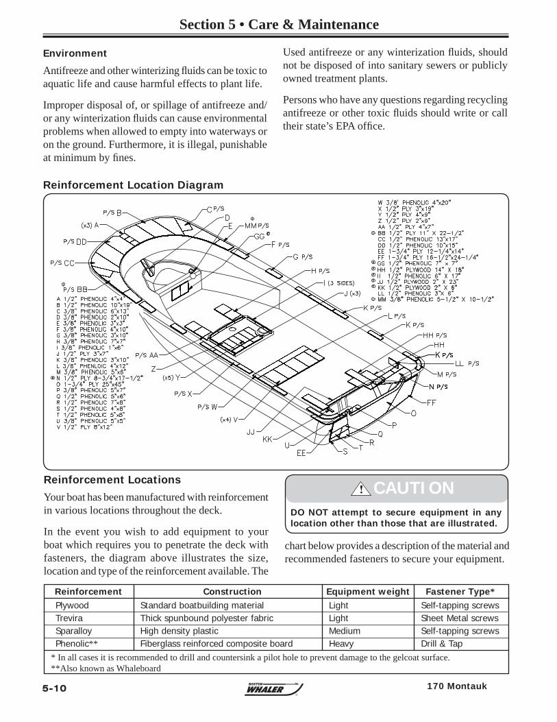
5-10
Section 5 • Care & Maintenance
R
170 Montauk
Antifreeze and other winterizing fl uids can be toxic to aquatic life and cause harmful effects to plant life.
Improper disposal of, or spillage of antifreeze and/or any winterization fl uids can cause environmental problems when allowed to empty into waterways or on the ground. Furthermore, it is illegal, punishable at minimum by fi nes.
Environment
Reinforcement LocationsYour boat has been manufactured with reinforcement in various locations throughout the deck.
In the event you wish to add equipment to your boat which requires you to penetrate the deck with fasteners, the diagram above illustrates the size, location and type of the reinforcement available. The
DO NOT attempt to secure equipment in any location other than those that are illustrated.
! CAUTION
* In all cases it is recommended to drill and countersink a pilot hole to prevent damage to the gelcoat surface.**Also known as Whaleboard
Reinforcement Construction Equipment weight Fastener Type*Plywood Standard boatbuilding material Light Self-tapping screwsTrevira Thick spunbound polyester fabric Light Sheet Metal screwsSparalloy High density plastic Medium Self-tapping screwsPhenolic** Fiberglass reinforced composite board Heavy Drill & Tap
chart below provides a description of the material and recommended fasteners to secure your equipment.
Reinforcement Location Diagram
Used antifreeze or any winterization fl uids, should not be disposed of into sanitary sewers or publicly owned treatment plants.
Persons who have any questions regarding recycling antifreeze or other toxic fl uids should write or call their state’s EPA offi ce.
5-11
Section 5 • Care & Maintenance
R
170 Montauk
MAINTENANCE LOG ENGINE SERVICED DATE HOURS BY MAINTENANCE PERFORMED
Fill out the log below after scheduled service or maintenance is performed.
NOTES
5-12
Section 5 • Care & Maintenance
R
170 Montauk
THIS PAGE LEFT INTENTIONALLY BLANK