Embed Size (px)
Citation preview
1
The Traditional Graphics Pipeline
Final Projects • Proposals due Thursday 4/8
– Proposed project summary – At least 3 related papers (read & summarized) – Description of series of test cases – Timeline & initial task assignment
• [ Homework 4 due: Thursday 4/22 ] • Final project progress post on LMS due: Monday 4/26 • [ Quiz 2: Fri 4/30 ] • In class work sessions: Tuesday 5/4 & Friday 5/7
(TA will meet with each group) • Reports Due: Monday 5/10 • Presentations: Wednesday 5/12, 1-5pm?
Last Time? • Participating Media • Measuring BRDFs • 3D Digitizing & Scattering • BSSRDFs
– Monte Carlo Simulation – Dipole Approximation
Today • Ray Casting / Tracing vs. Scan Conversion • Traditional Graphics Pipeline • Clipping • Rasterization/Scan Conversion
Ray Casting / Tracing • Advantages?
– Smooth variation of normal, silhouettes – Generality: can render anything that can be
intersected with a ray – Atomic operation, allows recursion
• Disadvantages? – Time complexity (N objects, R pixels) – Usually too slow for interactive applications – Hard to implement in hardware (lacks computation
coherence, must fit entire scene in memory)
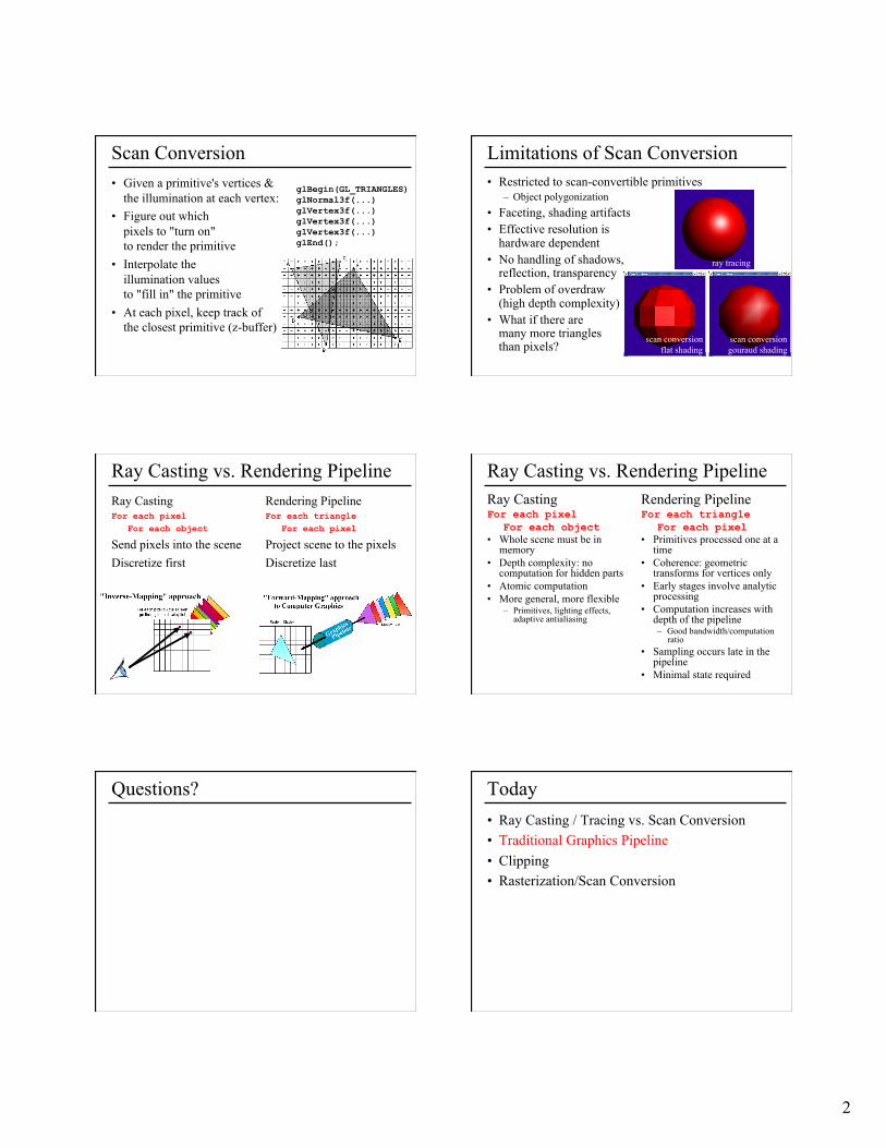
How Do We Render Interactively? • Use graphics hardware (the graphics pipeline), via
OpenGL, MesaGL, or DirectX
• Most global effects available in ray tracing will be sacrificed, but some can be approximated
Graphics Pipeline (OpenGL) Ray Tracing
2
Scan Conversion • Given a primitive's vertices &
the illumination at each vertex: • Figure out which
pixels to "turn on" to render the primitive
• Interpolate the illumination values to "fill in" the primitive
• At each pixel, keep track of the closest primitive (z-buffer)
glBegin(GL_TRIANGLES) glNormal3f(...) glVertex3f(...) glVertex3f(...) glVertex3f(...) glEnd();
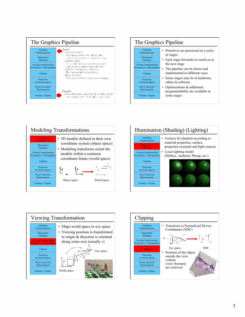
Limitations of Scan Conversion • Restricted to scan-convertible primitives
– Object polygonization • Faceting, shading artifacts • Effective resolution is
hardware dependent • No handling of shadows,
reflection, transparency • Problem of overdraw
(high depth complexity) • What if there are
many more triangles than pixels?
scan conversion gouraud shading
ray tracing
scan conversion flat shading
Ray Casting vs. Rendering Pipeline Ray Casting For each pixel
For each object
Send pixels into the scene Discretize first
Rendering Pipeline For each triangle
For each pixel
Project scene to the pixels Discretize last
Ray Casting For each pixel
For each object • Whole scene must be in
memory • Depth complexity: no
computation for hidden parts • Atomic computation • More general, more flexible
– Primitives, lighting effects, adaptive antialiasing
Rendering Pipeline For each triangle
For each pixel • Primitives processed one at a
time • Coherence: geometric
transforms for vertices only • Early stages involve analytic
processing • Computation increases with
depth of the pipeline – Good bandwidth/computation
ratio • Sampling occurs late in the
pipeline • Minimal state required
Ray Casting vs. Rendering Pipeline
Questions? Today • Ray Casting / Tracing vs. Scan Conversion • Traditional Graphics Pipeline • Clipping • Rasterization/Scan Conversion
3
The Graphics Pipeline Modeling
Transformations
Illumination (Shading)
Viewing Transformation (Perspective / Orthographic)
Clipping
Projection (to Screen Space)
Scan Conversion (Rasterization)
Visibility / Display
The Graphics Pipeline • Primitives are processed in a series
of stages • Each stage forwards its result on to
the next stage • The pipeline can be drawn and
implemented in different ways • Some stages may be in hardware,
others in software • Optimizations & additional
programmability are available at some stages
Modeling Transformations
Illumination (Shading)
Viewing Transformation (Perspective / Orthographic)
Clipping
Projection (to Screen Space)
Scan Conversion (Rasterization)
Visibility / Display
Modeling Transformations • 3D models defined in their own
coordinate system (object space) • Modeling transforms orient the
models within a common coordinate frame (world space)
Modeling Transformations
Illumination (Shading)
Viewing Transformation (Perspective / Orthographic)
Clipping
Projection (to Screen Space)
Scan Conversion (Rasterization)
Visibility / Display Object space World space
Illumination (Shading) (Lighting) • Vertices lit (shaded) according to
material properties, surface properties (normal) and light sources
• Local lighting model (Diffuse, Ambient, Phong, etc.)
Modeling Transformations
Illumination (Shading)
Viewing Transformation (Perspective / Orthographic)
Clipping
Projection (to Screen Space)
Scan Conversion (Rasterization)
Visibility / Display
Viewing Transformation • Maps world space to eye space • Viewing position is transformed
to origin & direction is oriented along some axis (usually z)
Modeling Transformations
Illumination (Shading)
Viewing Transformation (Perspective / Orthographic)
Clipping
Projection (to Screen Space)
Scan Conversion (Rasterization)
Visibility / Display
Eye space
World space
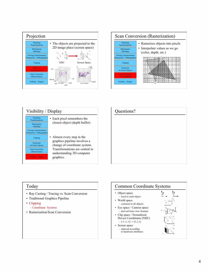
Clipping • Transform to Normalized Device
Coordinates (NDC)
• Portions of the object outside the view volume (view frustum) are removed
Modeling Transformations
Illumination (Shading)
Viewing Transformation (Perspective / Orthographic)
Clipping
Projection (to Screen Space)
Scan Conversion (Rasterization)
Visibility / Display
Eye space NDC
4
Projection • The objects are projected to the
2D image place (screen space) Modeling
Transformations
Illumination (Shading)
Viewing Transformation (Perspective / Orthographic)
Clipping
Projection (to Screen Space)
Scan Conversion (Rasterization)
Visibility / Display
NDC Screen Space
Scan Conversion (Rasterization) • Rasterizes objects into pixels • Interpolate values as we go
(color, depth, etc.)
Modeling Transformations
Illumination (Shading)
Viewing Transformation (Perspective / Orthographic)
Clipping
Projection (to Screen Space)
Scan Conversion (Rasterization)
Visibility / Display
Visibility / Display • Each pixel remembers the
closest object (depth buffer)
• Almost every step in the graphics pipeline involves a change of coordinate system. Transformations are central to understanding 3D computer graphics.
Modeling Transformations
Illumination (Shading)
Viewing Transformation (Perspective / Orthographic)
Clipping
Projection (to Screen Space)
Scan Conversion (Rasterization)
Visibility / Display
Questions?
Today • Ray Casting / Tracing vs. Scan Conversion • Traditional Graphics Pipeline • Clipping
– Coordinate Systems • Rasterization/Scan Conversion
Common Coordinate Systems • Object space
– local to each object • World space
– common to all objects • Eye space / Camera space
– derived from view frustum • Clip space / Normalized
Device Coordinates (NDC) – [-1,-1,-1] → [1,1,1]
• Screen space – indexed according
to hardware attributes
5
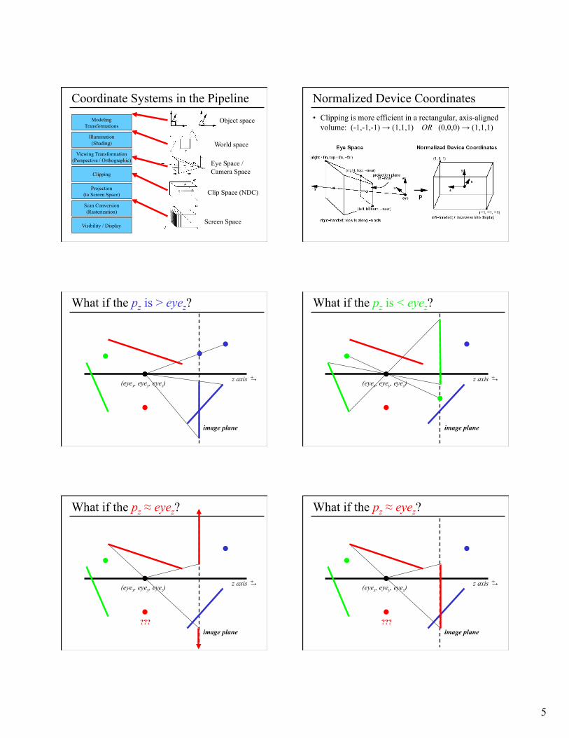
Coordinate Systems in the Pipeline Modeling
Transformations
Illumination (Shading)
Viewing Transformation (Perspective / Orthographic)
Clipping
Projection (to Screen Space)
Scan Conversion (Rasterization)
Visibility / Display
Object space
World space
Eye Space / Camera Space
Clip Space (NDC)
Screen Space
Normalized Device Coordinates • Clipping is more efficient in a rectangular, axis-aligned
volume: (-1,-1,-1) → (1,1,1) OR (0,0,0) → (1,1,1)
What if the pz is > eyez?
(eyex, eyey, eyez)
image plane
z axis → +
What if the pz is < eyez?
(eyex, eyey, eyez)
image plane
z axis → +
What if the pz ≈ eyez?
(eyex, eyey, eyez)
image plane ???
z axis → +
What if the pz ≈ eyez?
(eyex, eyey, eyez)
image plane ???
z axis → +
6
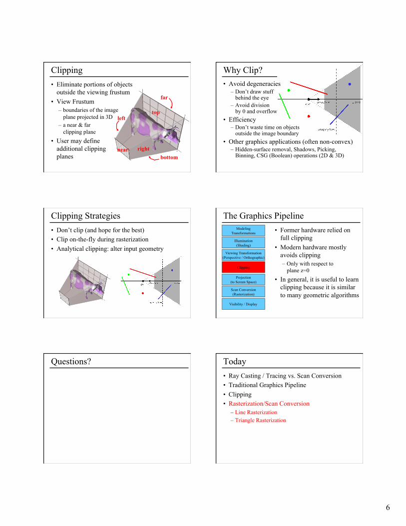
Clipping • Eliminate portions of objects
outside the viewing frustum • View Frustum
– boundaries of the image plane projected in 3D
– a near & far clipping plane
• User may define additional clipping planes bottom
top
right
left
near
far
Why Clip? • Avoid degeneracies
– Don’t draw stuff behind the eye
– Avoid division by 0 and overflow
• Efficiency – Don’t waste time on objects
outside the image boundary • Other graphics applications (often non-convex)
– Hidden-surface removal, Shadows, Picking, Binning, CSG (Boolean) operations (2D & 3D)
Clipping Strategies • Don’t clip (and hope for the best) • Clip on-the-fly during rasterization • Analytical clipping: alter input geometry
The Graphics Pipeline • Former hardware relied on
full clipping • Modern hardware mostly
avoids clipping – Only with respect to
plane z=0 • In general, it is useful to learn
clipping because it is similar to many geometric algorithms
Modeling Transformations
Illumination (Shading)
Viewing Transformation (Perspective / Orthographic)
Clipping
Projection (to Screen Space)
Scan Conversion (Rasterization)
Visibility / Display
Questions? Today • Ray Casting / Tracing vs. Scan Conversion • Traditional Graphics Pipeline • Clipping • Rasterization/Scan Conversion
– Line Rasterization – Triangle Rasterization
7
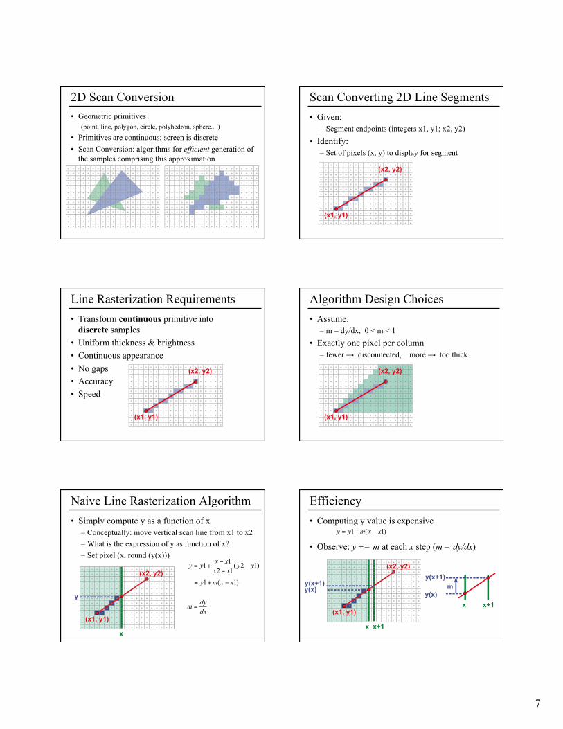
2D Scan Conversion • Geometric primitives
(point, line, polygon, circle, polyhedron, sphere... ) • Primitives are continuous; screen is discrete • Scan Conversion: algorithms for efficient generation of
the samples comprising this approximation
Scan Converting 2D Line Segments • Given:
– Segment endpoints (integers x1, y1; x2, y2) • Identify:
– Set of pixels (x, y) to display for segment
Line Rasterization Requirements • Transform continuous primitive into
discrete samples • Uniform thickness & brightness • Continuous appearance • No gaps • Accuracy • Speed
Algorithm Design Choices • Assume:
– m = dy/dx, 0 < m < 1 • Exactly one pixel per column
– fewer → disconnected, more → too thick
Naive Line Rasterization Algorithm • Simply compute y as a function of x
– Conceptually: move vertical scan line from x1 to x2 – What is the expression of y as function of x? – Set pixel (x, round (y(x)))
Efficiency • Computing y value is expensive
• Observe: y += m at each x step (m = dy/dx)
8
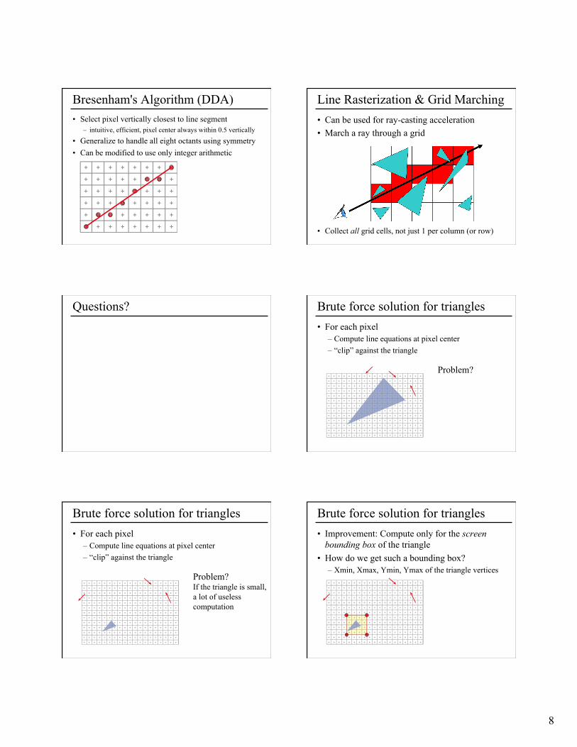
Bresenham's Algorithm (DDA) • Select pixel vertically closest to line segment
– intuitive, efficient, pixel center always within 0.5 vertically • Generalize to handle all eight octants using symmetry • Can be modified to use only integer arithmetic
Line Rasterization & Grid Marching • Can be used for ray-casting acceleration • March a ray through a grid
• Collect all grid cells, not just 1 per column (or row)
Questions? Brute force solution for triangles • For each pixel
– Compute line equations at pixel center – “clip” against the triangle
Problem?
Brute force solution for triangles • For each pixel
– Compute line equations at pixel center – “clip” against the triangle
Problem? If the triangle is small, a lot of useless computation
Brute force solution for triangles • Improvement: Compute only for the screen
bounding box of the triangle • How do we get such a bounding box?
– Xmin, Xmax, Ymin, Ymax of the triangle vertices
9
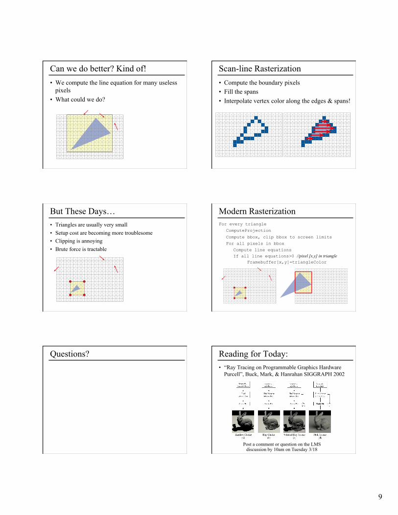
Can we do better? Kind of! • We compute the line equation for many useless
pixels • What could we do?
Scan-line Rasterization • Compute the boundary pixels • Fill the spans • Interpolate vertex color along the edges & spans!
But These Days… • Triangles are usually very small • Setup cost are becoming more troublesome • Clipping is annoying • Brute force is tractable
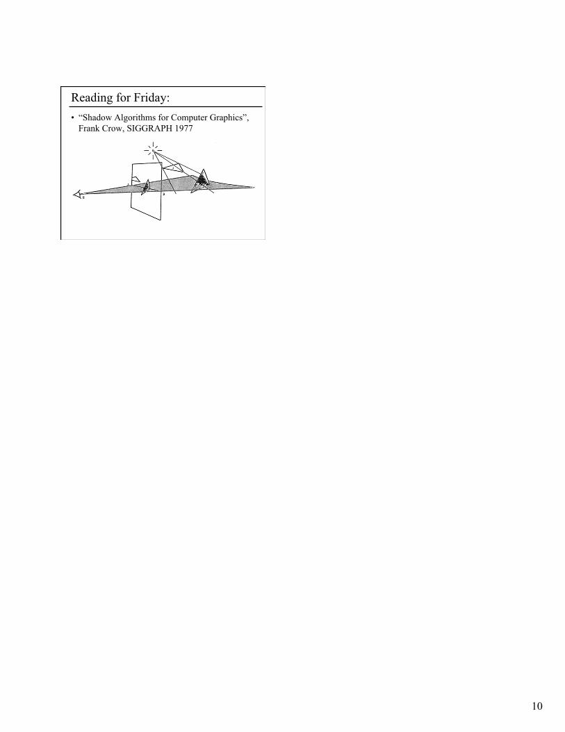
Modern Rasterization For every triangle
ComputeProjection
Compute bbox, clip bbox to screen limits
For all pixels in bbox
Compute line equations If all line equations>0 //pixel [x,y] in triangle
Framebuffer[x,y]=triangleColor
Questions? • “Ray Tracing on Programmable Graphics Hardware
Purcell”, Buck, Mark, & Hanrahan SIGGRAPH 2002
Reading for Today:
Post a comment or question on the LMS discussion by 10am on Tuesday 3/18
10
Reading for Friday: • “Shadow Algorithms for Computer Graphics”,
Frank Crow, SIGGRAPH 1977


![Graphics Pipelinebarbic.usc.edu/cs420-s18/03-pipeline/03-pipeline.pdfLecture 3 Graphics Pipeline Graphics Pipeline Primitives: Points, Lines, Triangles [Angel Ch. 2] 1 . Graphics Pipeline](https://img.pdfslide.us/doc/110x75/611fe83badc8f839e462493e/graphics-lecture-3-graphics-pipeline-graphics-pipeline-primitives-points-lines.jpg)